alaska applied sciences, inc. comments - thin-shell
TRANSCRIPT
DOCKETED Docket Number: 20-DECARB-01
Project Title: Building Initiative for Low-Emissions Development (BUILD)
Program
TN #: 234277
Document Title: Alaska Applied Sciences, Inc. Comments - Thin-shell concrete
structures, multi-purpose, for low embodied and operating
energy and durability
Description: N/A
Filer: System
Organization: Alaska Applied Sciences, Inc.
Submitter Role: Public
Submission Date: 8/8/2020 9:02:54 AM
Docketed Date: 8/10/2020

Comment Received From: Alaska Applied Sciences, Inc. Submitted On: 8/8/2020
Docket Number: 20-DECARB-01
Thin-shell concrete structures, multi-purpose, for low embodied and operating energy and durability
Thin-shell concrete structures, necessarily quasi-spherical in shape, consequently limited to large radii of curvature to achieve structural integrity, also provide durable,
low-cost, multi-purpose shelter with low embodied and operating and maintenance (O&M) costs. Built on-site, about one structure per forms set, per four days. California's
extant concrete construction industry will easily adapt to this construction method, for residential and diverse uses -- perhaps, at first, to accommodate a wave of COVID-caused homelessness, and to welcome temporary ag workers.
Structure cost will depend primarily upon finish level: insulation (interior: sprayed, closed-cell urethane foam); plumbing and wiring; cabinetry and appliances -- if any.
Concrete shell cost is relatively low; shell thickness ~ 2 cm; < 1 inch. Please consider scaling-up our proof-of-concept, scale model, prototype work from 2009, in Juneau, AK. About $ 250 - 500 K investment will be needed for CAD, building
the tools by which the concrete forms sets may be manufactured, by which the thin-shell concrete structures are built on-site, and for building several sets of forms for field tests
and shelters production. Please see: www.AlaskaAppliedSciences.com/thin-shell-concrete-structures Please see attached slide presentation; larger slide presentation available on request. The original forms set, by which the prototype scale models were
built in 1990, are available for further R&D use, although they were not designed for, nor probably durable enough for, production of more than a few structures.
Additional submitted attachment is included below.

1 Juneau, AK 1977: 16’ diameter concrete dome: ½” thick, ~ 5/8 sphere
Thin-shell Concrete Dome Rapid Construction Method
for Remote Sites and Severe Climates
Bill Leighty, Principal Alaska Applied Sciences, Inc. Juneau, AK [email protected] Rev: 15 Jan 10
Thin-shell Concrete Structures for Low Embodied and Operating Energy
and Durability
Bill Leighty, Principal Alaska Applied Sciences, Inc. Juneau, AK [email protected] Rev: 15 Jan 10 Rev: 8 Aug 20
TechConnect 2015 Abstract # 747
Washington, DC 14-18 June 15
For: CEC 20-DECARB-01 Submitted: 8 Aug 20
2
Alaska Applied Sciences, Inc. Bill Leighty, Principal [email protected] 907-586-1426 206-719-5554
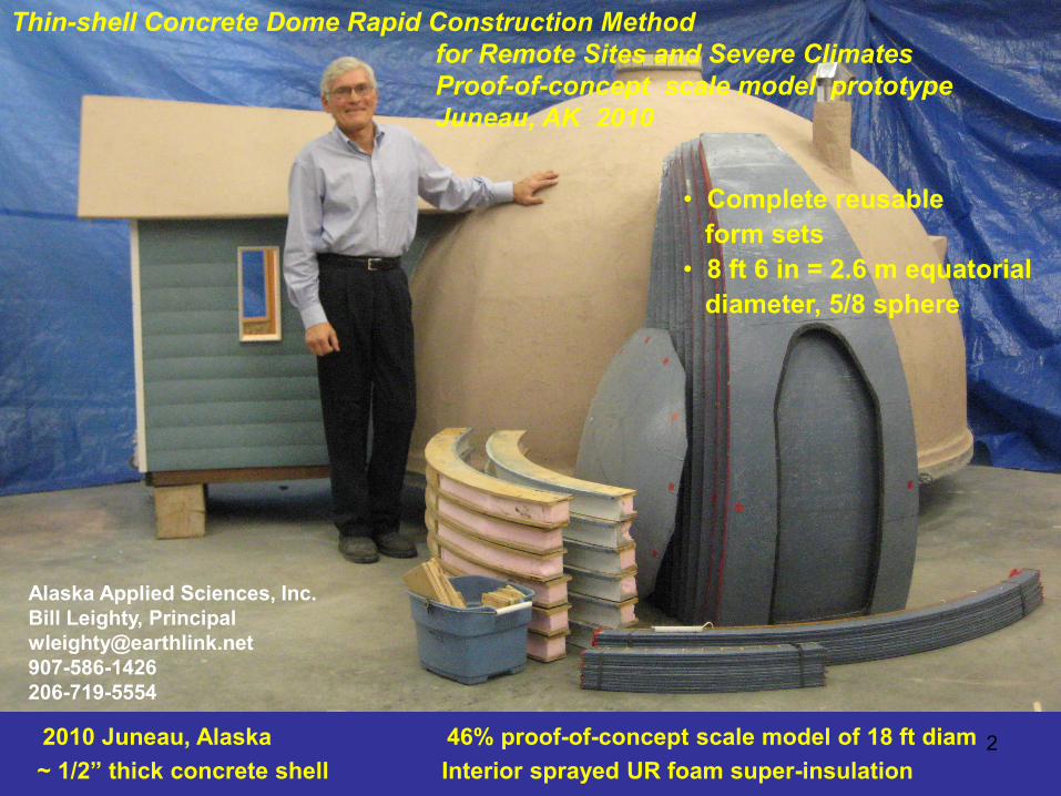
2010 Juneau, Alaska 46% proof-of-concept scale model of 18 ft diam ~ 1/2” thick concrete shell Interior sprayed UR foam super-insulation
Thin-shell Concrete Dome Rapid Construction Method for Remote Sites and Severe Climates Proof-of-concept scale model prototype Juneau, AK 2010
• Complete reusable form sets • 8 ft 6 in = 2.6 m equatorial diameter, 5/8 sphere
3

4
Goals 1. Minimize imported:
a. Materials, including aggregate b. Tooling c. Tools d. Expert labor e. Use local sand, water, semi-skilled labor f. Minimize Earth impact
2. Build many on-site, in-situ a. Reusable forms set b. One every 3 – 4 days
3. Non-ferrous primary reinforcement 4. Spray-in insulation 5. Durable, strong, fireproof, vermin-proof, waterproof 6. Earth sheltered: compatible 7. Alaska village housing replace
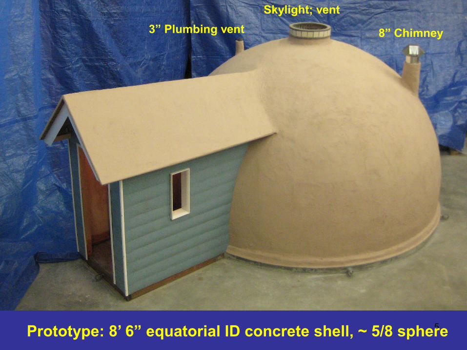
5 Prototype: 8’ 6” equatorial ID concrete shell, ~ 5/8 sphere
Skylight; vent
8” Chimney 3” Plumbing vent
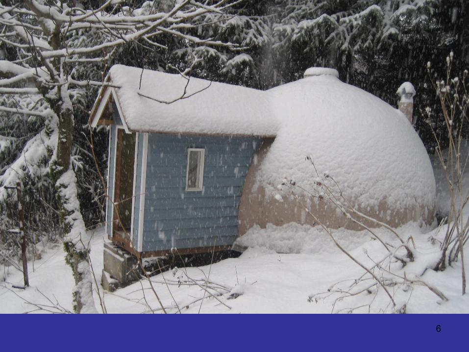
6

7
8
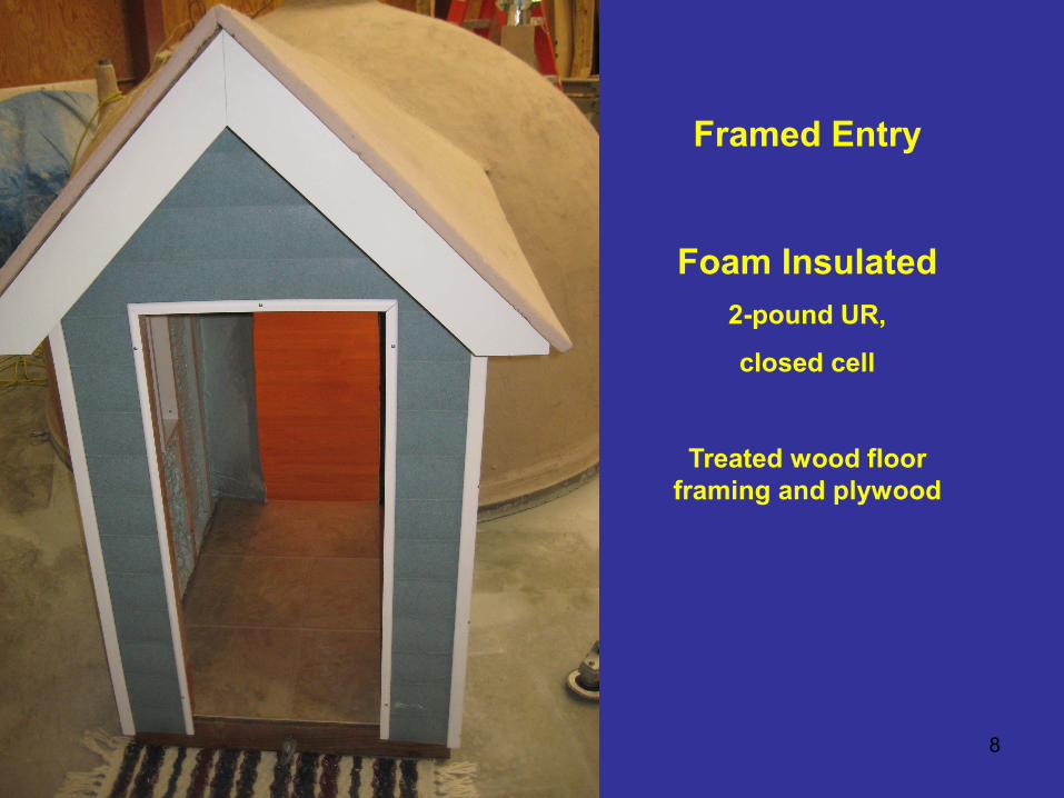
Framed Entry
Foam Insulated 2-pound UR,
closed cell
Treated wood floor framing and plywood
9
10

11
Proof - of – Concept Prototype Slide 1 of 3
• 46% scale model of 18’ ID full-size concrete dome • ~ 5/8 sphere (volume) • 8’ 6” equatorial ID (concrete shell) • < 1/2” thick concrete shell
– Need engineering to confirm adequate structurally at full scale – FEA necessary for stress concentrations – Integral waterproofing: no coating needed – Earth berming or burying compatible
• Unique, reusable tooling • Mortar:
– Rich, portland cement – Sand only aggregate – High-fiber
• Reinforcement: – Primary: Chomarat C-Grid – Secondary: Fibermesh 150
• 13-part dome form (12 side + top cap) • Teflon dome form release surface • UR foam insulated + protection layer
12
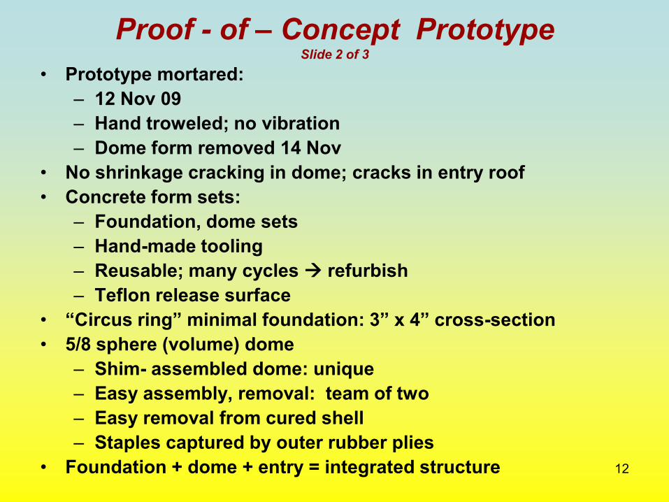
Proof - of – Concept Prototype Slide 2 of 3
• Prototype mortared: – 12 Nov 09 – Hand troweled; no vibration – Dome form removed 14 Nov
• No shrinkage cracking in dome; cracks in entry roof • Concrete form sets:
– Foundation, dome sets – Hand-made tooling – Reusable; many cycles refurbish – Teflon release surface
• “Circus ring” minimal foundation: 3” x 4” cross-section • 5/8 sphere (volume) dome
– Shim- assembled dome: unique – Easy assembly, removal: team of two – Easy removal from cured shell – Staples captured by outer rubber plies
• Foundation + dome + entry = integrated structure
13
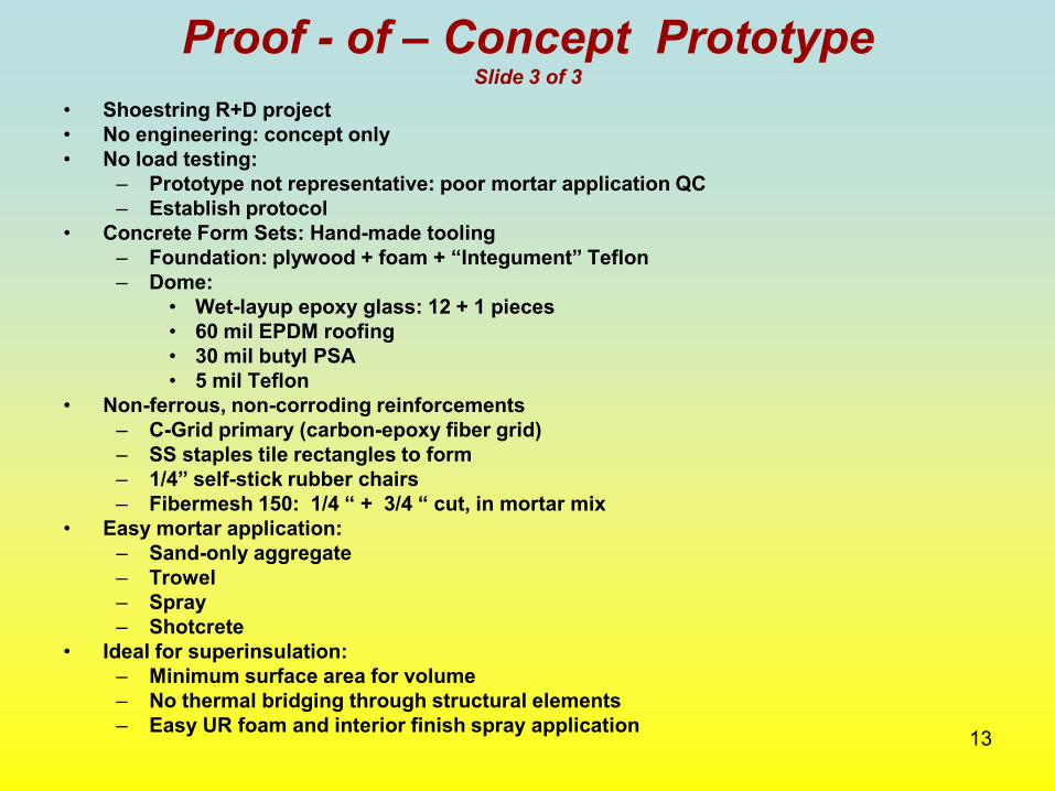
Proof - of – Concept Prototype Slide 3 of 3
• Shoestring R+D project • No engineering: concept only • No load testing:
– Prototype not representative: poor mortar application QC – Establish protocol
• Concrete Form Sets: Hand-made tooling – Foundation: plywood + foam + “Integument” Teflon – Dome:
• Wet-layup epoxy glass: 12 + 1 pieces • 60 mil EPDM roofing • 30 mil butyl PSA • 5 mil Teflon
• Non-ferrous, non-corroding reinforcements – C-Grid primary (carbon-epoxy fiber grid) – SS staples tile rectangles to form – 1/4” self-stick rubber chairs – Fibermesh 150: 1/4 “ + 3/4 “ cut, in mortar mix
• Easy mortar application: – Sand-only aggregate – Trowel – Spray – Shotcrete
• Ideal for superinsulation: – Minimum surface area for volume – No thermal bridging through structural elements – Easy UR foam and interior finish spray application

14
Concepts Proven Slide 1 of 2
1. Dome form removable, reusable a. Removable shims liberate segments b. Teflon surface releases concrete
2. Non-ferrous, non-corroding reinforcements a. C-Grid primary (carbon-epoxy fiber grid)
I. 1/4” self-stick rubber chairs center C-Grid II. Rectangles easily “tile” spherical surface III. SS staples tile C-Grid rectangles to form
b. Fibermesh 150: 1/4 “ + 3/4 “ cut, in mortar mix 3. < 1/2” thick concrete shell achievable 4. Easy mortar application
a. Trowel proven, but poor QC in prototype b. Unproven: Spray or shotcrete
15
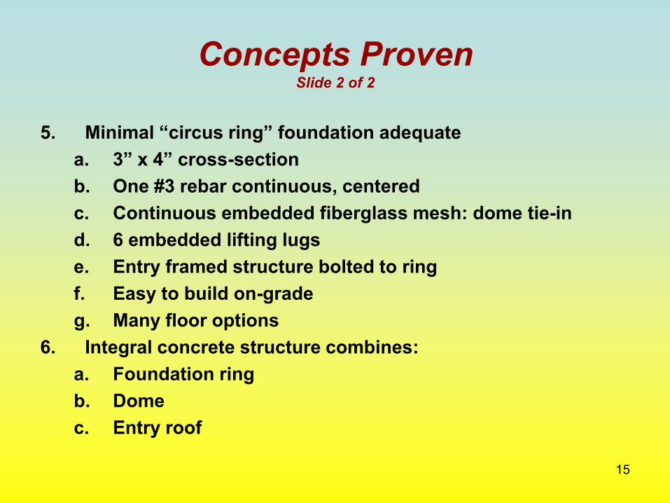
Concepts Proven Slide 2 of 2
5. Minimal “circus ring” foundation adequate a. 3” x 4” cross-section b. One #3 rebar continuous, centered c. Continuous embedded fiberglass mesh: dome tie-in d. 6 embedded lifting lugs e. Entry framed structure bolted to ring f. Easy to build on-grade g. Many floor options
6. Integral concrete structure combines: a. Foundation ring b. Dome c. Entry roof
16
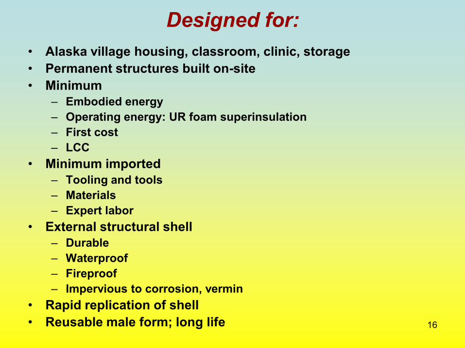
Designed for: • Alaska village housing, classroom, clinic, storage • Permanent structures built on-site • Minimum
– Embodied energy – Operating energy: UR foam superinsulation – First cost – LCC
• Minimum imported – Tooling and tools – Materials – Expert labor
• External structural shell – Durable – Waterproof – Fireproof – Impervious to corrosion, vermin
• Rapid replication of shell • Reusable male form; long life

17
Also useful for:
• Strategies combining development + combat • Afghanistan and others • Civilian • Military • Disaster relief • Low cost housing • Classrooms • Clinics • Storage • Emergency shelter • Potentially transportable

18
Dome Reusable Form System Slide 1 of 2
• Fiberglass structure • 13 pieces
– 12 identical side “orange peel” segments; – Door opening in one – Integral threaded inserts for bolted assembly
• Top cap • Outer adhered plies:
– 60 mil EPDM unreinforced roofing membrane – “Integument”:
• P500W-MX-36 Fluorogrip MX membrane • 30 mil butyl adhesive • 5 mil Teflon film concrete release surface • Adhered over 60 mil EPDM
– 95 mil outer plies capture primary reinforcement staples

19
Dome Reusable Form System Slide 2 of 2
• Two-person assembly and removal • 12 removable side shims
– Assemble between 12 side segments – 1/4” plywood + “Integument” Teflon – ~ 5/16” total thickness
• 12 removable bottom shims – Assemble under 12 side segments – 1/4” plywood + “Integument” Teflon – ~ 5/16” total thickness
• 12 removable sheet steel skid plates – Placed on concrete foundation – Ease bottom shim removal
20
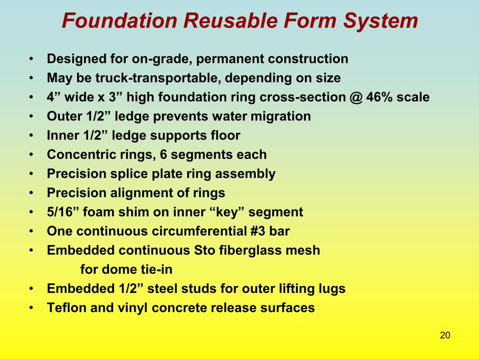
Foundation Reusable Form System • Designed for on-grade, permanent construction • May be truck-transportable, depending on size • 4” wide x 3” high foundation ring cross-section @ 46% scale • Outer 1/2” ledge prevents water migration • Inner 1/2” ledge supports floor • Concentric rings, 6 segments each • Precision splice plate ring assembly • Precision alignment of rings • 5/16” foam shim on inner “key” segment • One continuous circumferential #3 bar • Embedded continuous Sto fiberglass mesh for dome tie-in • Embedded 1/2” steel studs for outer lifting lugs • Teflon and vinyl concrete release surfaces
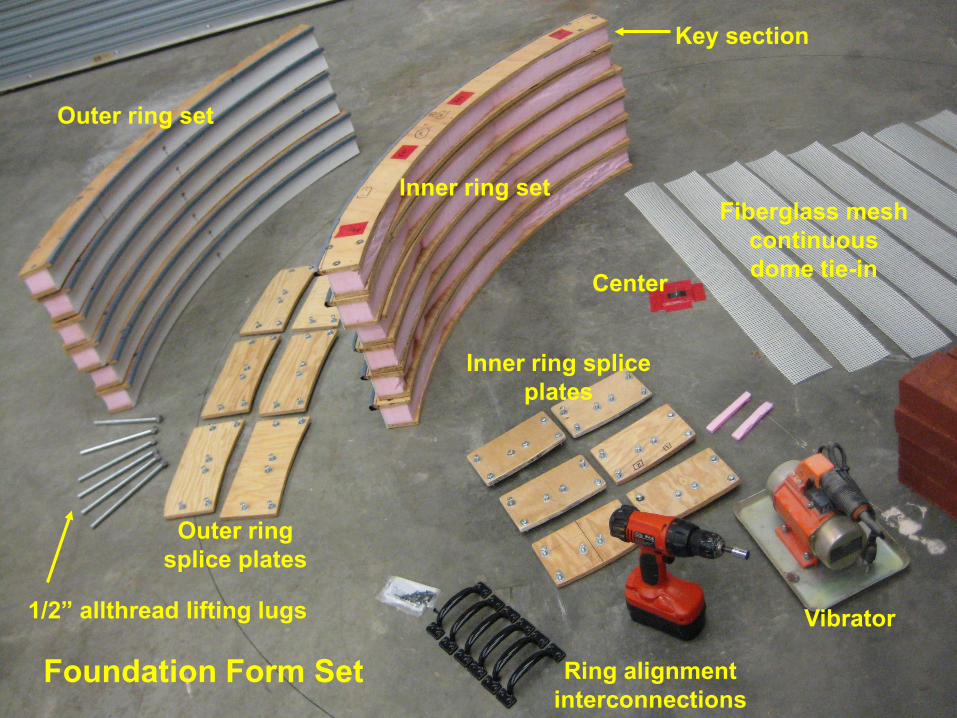
21 Foundation Form Set
Outer ring set
Inner ring set
Key section
1/2” allthread lifting lugs
Outer ring splice plates
Inner ring splice plates
Ring alignment interconnections
Center
Vibrator
Fiberglass mesh continuous dome tie-in

22 Assembled foundation form, ready for pour
Fiberglass mesh dome tie-in
Center “Key” segment
Precision ring alignment fixtures
Lifting lug studs (6 pl)
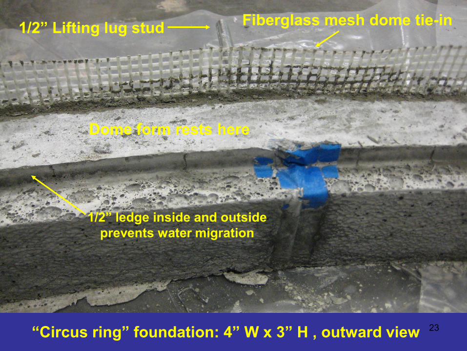
23 “Circus ring” foundation: 4” W x 3” H , outward view
1/2” Lifting lug stud Fiberglass mesh dome tie-in
1/2” ledge inside and outside prevents water migration
Dome form rests here
24
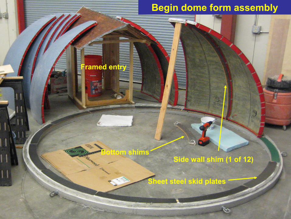
Begin dome form assembly
Side wall shim (1 of 12) Bottom shims
Framed entry
Sheet steel skid plates
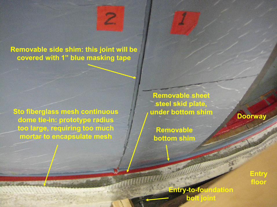
25
Entry floor
Entry-to-foundation bolt joint
Sto fiberglass mesh continuous dome tie-in: prototype radius too large, requiring too much mortar to encapsulate mesh
Doorway
Removable bottom shim
Removable side shim: this joint will be covered with 1” blue masking tape
Removable sheet steel skid plate,
under bottom shim
26
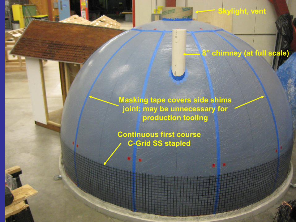
Continuous first course C-Grid SS stapled
Masking tape covers side shims joint; may be unnecessary for
production tooling
Skylight, vent
8” chimney (at full scale)
27
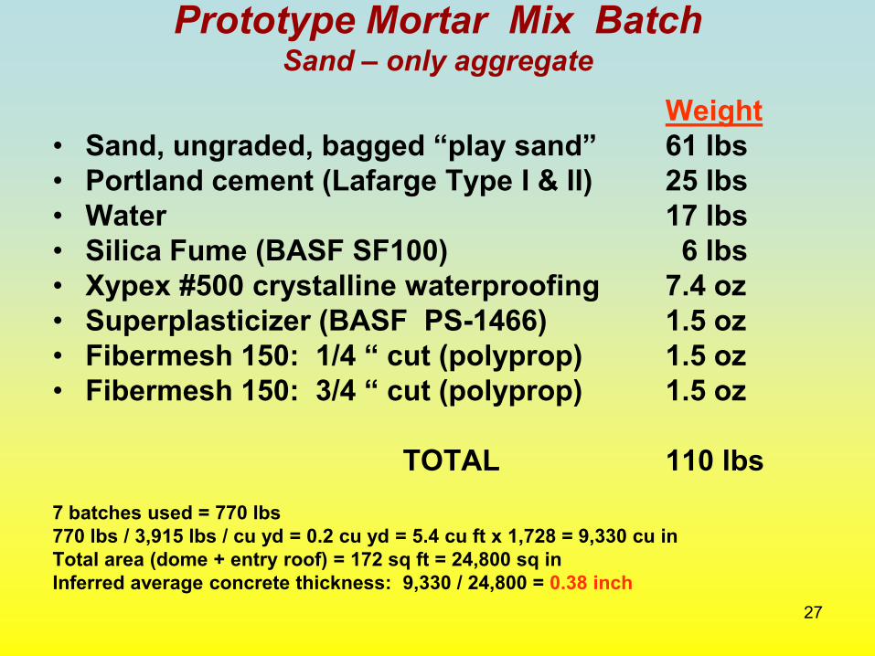
Prototype Mortar Mix Batch Sand – only aggregate
Weight • Sand, ungraded, bagged “play sand” 61 lbs • Portland cement (Lafarge Type I & II) 25 lbs • Water 17 lbs • Silica Fume (BASF SF100) 6 lbs • Xypex #500 crystalline waterproofing 7.4 oz • Superplasticizer (BASF PS-1466) 1.5 oz • Fibermesh 150: 1/4 “ cut (polyprop) 1.5 oz • Fibermesh 150: 3/4 “ cut (polyprop) 1.5 oz
TOTAL 110 lbs 7 batches used = 770 lbs 770 lbs / 3,915 lbs / cu yd = 0.2 cu yd = 5.4 cu ft x 1,728 = 9,330 cu in Total area (dome + entry roof) = 172 sq ft = 24,800 sq in Inferred average concrete thickness: 9,330 / 24,800 = 0.38 inch
28
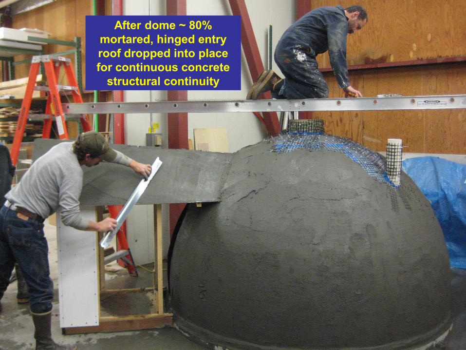
After dome ~ 80% mortared, hinged entry roof dropped into place for continuous concrete
structural continuity

29
Hinged Entry roof dropped into place
Continuous C-Grid embedded for
structural integrity of dome and entry
Entry roof hinge
Removable entry roof form
Z-flashing (4 pcs)
30
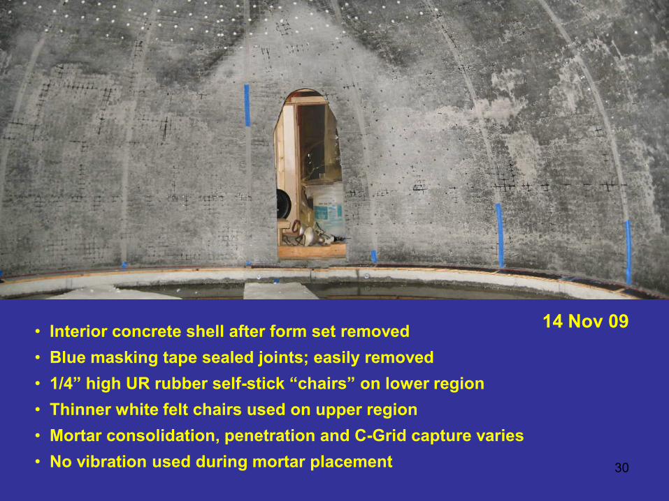
• Interior concrete shell after form set removed • Blue masking tape sealed joints; easily removed • 1/4” high UR rubber self-stick “chairs” on lower region • Thinner white felt chairs used on upper region • Mortar consolidation, penetration and C-Grid capture varies • No vibration used during mortar placement
14 Nov 09
31
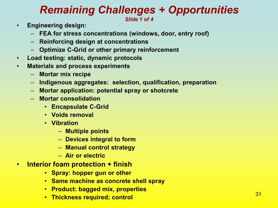
Remaining Challenges + Opportunities Slide 1 of 4
• Engineering design: – FEA for stress concentrations (windows, door, entry roof) – Reinforcing design at concentrations – Optimize C-Grid or other primary reinforcement
• Load testing: static, dynamic protocols • Materials and process experiments
– Mortar mix recipe – Indigenous aggregates: selection, qualification, preparation – Mortar application: potential spray or shotcrete – Mortar consolidation
• Encapsulate C-Grid • Voids removal • Vibration
– Multiple points – Devices integral to form – Manual control strategy – Air or electric
• Interior foam protection + finish • Spray: hopper gun or other • Same machine as concrete shell spray • Product: bagged mix, properties • Thickness required; control
32
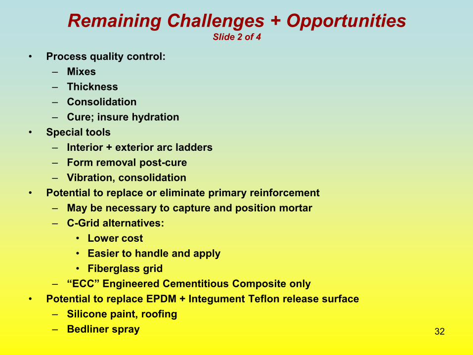
Remaining Challenges + Opportunities Slide 2 of 4
• Process quality control: – Mixes – Thickness – Consolidation – Cure; insure hydration
• Special tools – Interior + exterior arc ladders – Form removal post-cure – Vibration, consolidation
• Potential to replace or eliminate primary reinforcement – May be necessary to capture and position mortar – C-Grid alternatives:
• Lower cost • Easier to handle and apply • Fiberglass grid
– “ECC” Engineered Cementitious Composite only • Potential to replace EPDM + Integument Teflon release surface
– Silicone paint, roofing – Bedliner spray
33
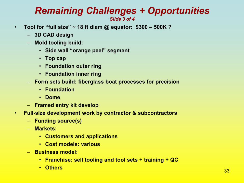
Remaining Challenges + Opportunities Slide 3 of 4
• Tool for “full size” ~ 18 ft diam @ equator: $300 – 500K ? – 3D CAD design – Mold tooling build:
• Side wall “orange peel” segment • Top cap • Foundation outer ring • Foundation inner ring
– Form sets build: fiberglass boat processes for precision • Foundation • Dome
– Framed entry kit develop • Full-size development work by contractor & subcontractors
– Funding source(s) – Markets:
• Customers and applications • Cost models: various
– Business model: • Franchise: sell tooling and tool sets + training + QC • Others
34
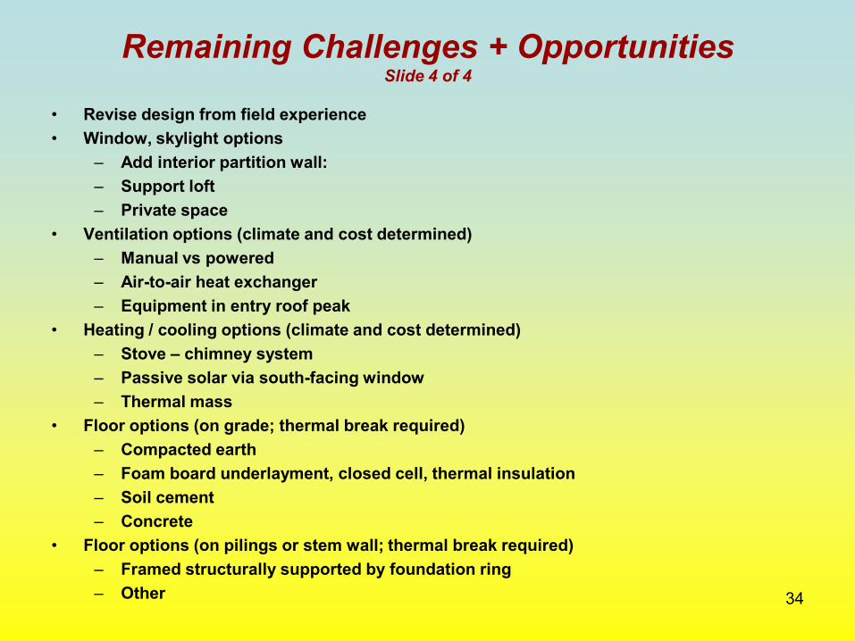
Remaining Challenges + Opportunities Slide 4 of 4
• Revise design from field experience • Window, skylight options
– Add interior partition wall: – Support loft – Private space
• Ventilation options (climate and cost determined) – Manual vs powered – Air-to-air heat exchanger – Equipment in entry roof peak
• Heating / cooling options (climate and cost determined) – Stove – chimney system – Passive solar via south-facing window – Thermal mass
• Floor options (on grade; thermal break required) – Compacted earth – Foam board underlayment, closed cell, thermal insulation – Soil cement – Concrete
• Floor options (on pilings or stem wall; thermal break required) – Framed structurally supported by foundation ring – Other
35
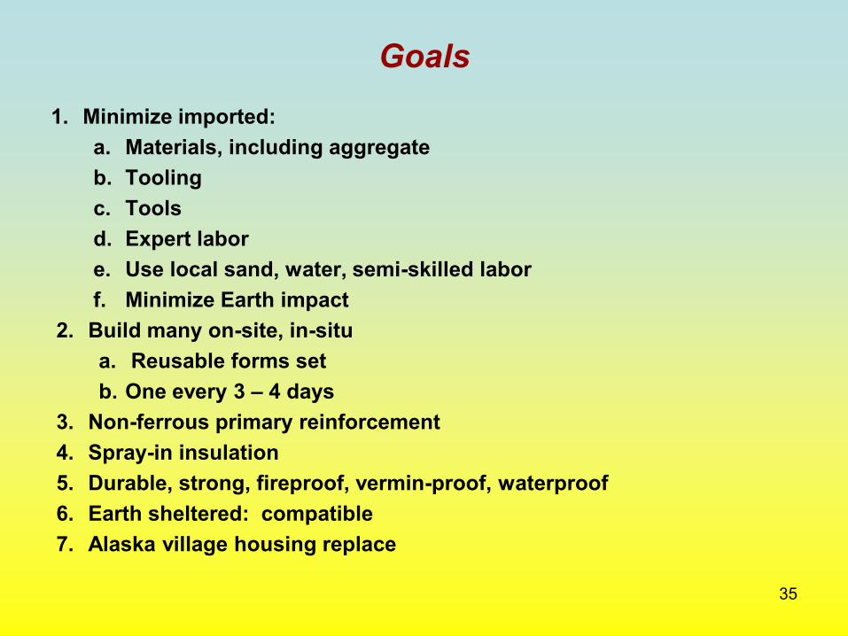
Goals 1. Minimize imported:
a. Materials, including aggregate b. Tooling c. Tools d. Expert labor e. Use local sand, water, semi-skilled labor f. Minimize Earth impact
2. Build many on-site, in-situ a. Reusable forms set b. One every 3 – 4 days
3. Non-ferrous primary reinforcement 4. Spray-in insulation 5. Durable, strong, fireproof, vermin-proof, waterproof 6. Earth sheltered: compatible 7. Alaska village housing replace
36
References
Chomarat NA http://carbongrid.com/ "Broadway, Andrew" <[email protected]> Integument http://www.integument.com/ "Jennifer Smyth" <[email protected]> CCHRC (Cold Climate Housing Research Center, Fairbanks, AK) http://www.cchrc.org/ ALAN WILSON [email protected] Marquam George [email protected] [email protected], [email protected], [email protected], [email protected] Xypex http://www.xypex.com/ “Les Faure” <[email protected]> Intershelter http://intershelter.com/ Don Kubley (907) 789-9273 Flexible concrete Prof. V. S. Li, University of Michigan Prof. Michael Lepech, Stanford University BASF (superplasticizer, silica fume, fibermesh) Sto (fiberglass mesh, SilcoLastic paint)

37 Juneau, AK 1977: 16’ diameter concrete dome: ½” thick, ~ 5/8 sphere
Thin-shell Concrete Dome Rapid Construction Method
for Remote Sites and Severe Climates
Bill Leighty, Principal Alaska Applied Sciences, Inc. Juneau, AK [email protected] Rev: 15 Jan 10
Thin-shell Concrete Structures for Low Embodied and Operating Energy
and Durability
Bill Leighty, Principal Alaska Applied Sciences, Inc. Juneau, AK [email protected] Rev: 15 Jan 10 Rev: 8 Aug 20
TechConnect 2015 Abstract # 747
Washington, DC 14-18 June 15
For: CEC 20-DECARB-01 Submitted: 8 Aug 20