alaskan way viaduct and seawall replacement … · washington state department of transportation...
TRANSCRIPT

MARCH 2004
Draft Environmental Impact StatementAppendix S Water Resources Discipline Report
SR 99: ALASKAN WAY VIADUCT &SEAWALL REPLACEMENT PROJECT
Submitted by:PARSONS BRINCKERHOFF QUADE & DOUGLAS, INC.
Prepared by:PARAMETRIX

This Page Intentionally Left Blank

SR 99: Alaskan Way Viaduct & Seawall Replacement Project March 2004 Water Resources Discipline Report Draft EIS
SR 99: ALASKAN WAY VIADUCT & SEAWALL REPLACEMENT PROJECT
Draft EIS Water Resources Discipline Report
AGREEMENT NO. Y-7888 FHWA-WA-EIS-04-01-D
Submitted to: Washington State Department of Transportation Alaskan Way Viaduct and Seawall Replacement Project Office 999 Third Avenue, Suite 2424 Seattle, WA 98104
The SR 99: Alaskan Way Viaduct & Seawall Replacement Project is a joint effort between the Washington State Department of Transportation (WSDOT), the City of Seattle, and the Federal Highway Administration (FHWA). To conduct this project, WSDOT contracted with:
Parsons Brinckerhoff Quade & Douglas, Inc. 999 Third Avenue, Suite 2200 Seattle, WA 98104
In association with: BERGER/ABAM Engineers Inc. BJT Associates David Evans and Associates, Inc. Entech Northwest EnviroIssues, Inc. Harvey Parker & Associates, Inc. Jacobs Civil Inc. Larson Anthropological Archaeological Services Limited Mimi Sheridan, AICP Parametrix Preston, Gates, Ellis, LLP ROMA Design Group RoseWater Engineering, Inc. Shannon & Wilson, Inc. Taylor Associates, Inc. Tom Warne and Associates, LLC William P. Ott

This Page Intentionally Left Blank

SR 99: Alaskan Way Viaduct & Seawall Replacement Project March 2004 Water Resources Discipline Report i Draft EIS
TABLE OF CONTENTS Chapter 1 Summary...............................................................................................................................................................1
1.1 Affected Environment................................................................................................................................................1 1.2 Summary of Water Quality Evaluation Methods and Assumptions...................................................................2 1.3 Water and Sediment Quality Concerns..................................................................................................................3 1.4 Impact Summary........................................................................................................................................................4
1.4.1 Operational Impacts....................................................................................................................................... 4 1.4.2 Construction Impacts..................................................................................................................................... 5
1.5 Mitigation Summary...................................................................................................................................................5 1.5.1 Operational Mitigation.................................................................................................................................... 5 1.5.2 Construction Mitigation.................................................................................................................................. 5
1.6 Compliance With Surface Water-Related Plans and Policies..........................................................................6
Chapter 2 Studies and Coordination ................................................................................................................................7
Chapter 3 Affected Environment.......................................................................................................................................9 3.1 Affected Environment Methods...............................................................................................................................9 3.2 Affected Environment Introduction..........................................................................................................................9 3.3 Duwamish River.......................................................................................................................................................23
3.3.1 Lander Sub-basin.........................................................................................................................................23 3.4 Elliott Bay..................................................................................................................................................................24
3.4.1 Royal Brougham Sub-basin........................................................................................................................25 3.4.2 Washington Sub-basin................................................................................................................................26 3.4.3 Madison Sub-basin......................................................................................................................................26 3.4.4 Seneca Sub-basin........................................................................................................................................27 3.4.5 University Sub-basin....................................................................................................................................27 3.4.6 Pine Sub-basin.............................................................................................................................................27 3.4.7 “S” Sub-basins..............................................................................................................................................27 3.4.8 T46 Sub-basin...............................................................................................................................................28
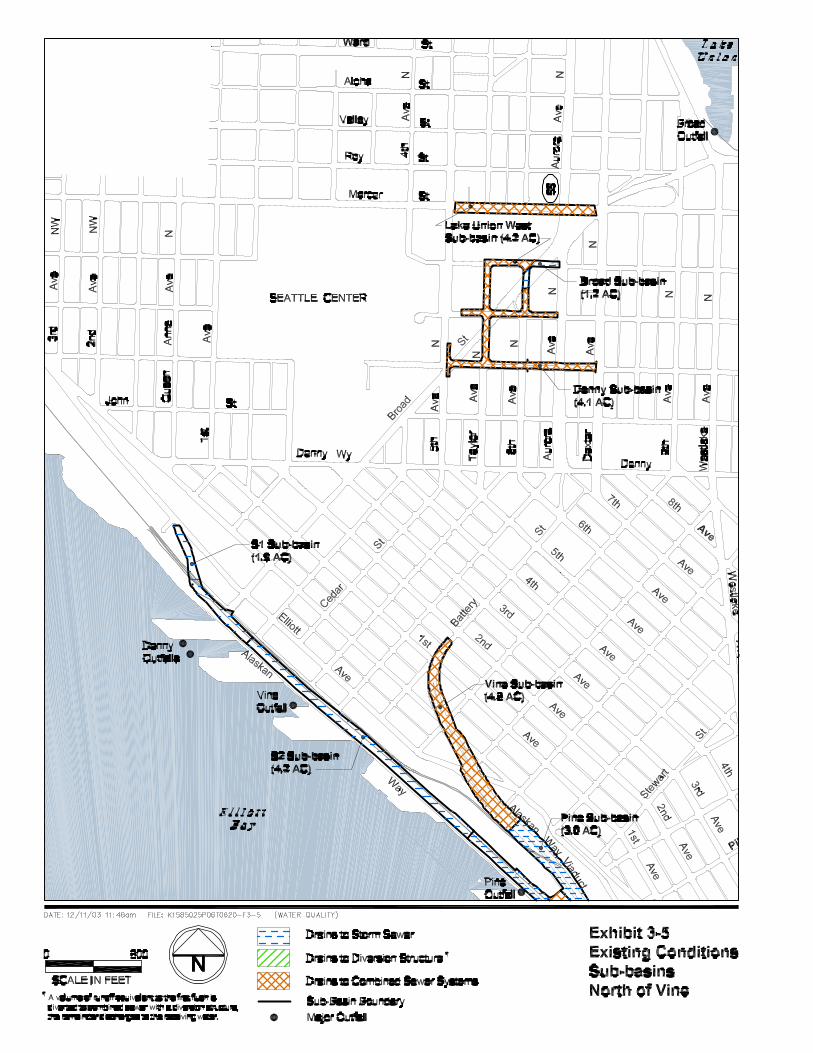
3.5 Puget Sound.............................................................................................................................................................28 3.5.1 King Sub-basin.............................................................................................................................................29 3.5.2 Pike Sub-basin..............................................................................................................................................29 3.5.3 Vine Sub-basin.............................................................................................................................................29 3.5.4 Denny Sub-basin..........................................................................................................................................30 3.5.5 Lake Union West Sub-basin.......................................................................................................................30
3.6 Lake Union................................................................................................................................................................30 3.6.1 Broad Sub-basin...........................................................................................................................................31
3.7 Nearshore Sediments.............................................................................................................................................31 3.7.1 Duwamish River ...........................................................................................................................................31 3.7.2 Elliott Bay.......................................................................................................................................................32 3.7.3 Lake Union....................................................................................................................................................37
Chapter 4 Methodology......................................................................................................................................................39 4.1 Operational Impacts Introduction..........................................................................................................................39
4.1.1 Annual Pollutant Load.................................................................................................................................39 4.1.2 Discharge Location......................................................................................................................................41
4.2 Stormwater Management Approaches................................................................................................................41 4.2.1 South of S. Royal Brougham Way.............................................................................................................41 4.2.2 Central Business District.............................................................................................................................41

SR 99: Alaskan Way Viaduct & Seawall Replacement Project March 2004 Water Resources Discipline Report ii Draft EIS
4.2.3 North of Vine Street .....................................................................................................................................53 4.3 Stormwater Modeling..............................................................................................................................................53
4.3.1 Stormwater Model – Inputs.........................................................................................................................53 4.3.2 Annual Load to the Environment...............................................................................................................67
4.4 Construction Impacts Methods..............................................................................................................................67 4.4.1 Temporary Erosion and Sediment Control Measures............................................................................67 4.4.2 Stormwater Treatment for Temporary Structures...................................................................................67 4.4.3 Dewatering....................................................................................................................................................67 4.4.4 In-Water Work...............................................................................................................................................67 4.4.5 Staging Areas ...............................................................................................................................................67
Chapter 5 Operational Impacts and Benefits...............................................................................................................69 5.1 No Build Alternative.................................................................................................................................................71
5.1.1 Scenario 1 – Continued Operation of the Viaduct and Seawall With Continued Maintenance................................................................................................................................................ 71
5.1.2 Scenario 2 – Sudden Unplanned Loss of the Viaduct and/or Seawall Without Major Collapse or Injury ....................................................................................................................................... 71
5.1.3 Scenario 3 – Catastrophic Failure and Collapse of the Viaduct and/or Seawall................................ 71 5.2 Rebuild Alternative ..................................................................................................................................................72
5.2.1 Duwamish River ...........................................................................................................................................72 5.2.2 Elliott Bay.......................................................................................................................................................73 5.2.3 Puget Sound.................................................................................................................................................74 5.2.4 Lake Union....................................................................................................................................................74
5.3 Aerial Alternative ......................................................................................................................................................74 5.3.1 Duwamish River ...........................................................................................................................................75 5.3.2 Elliott Bay.......................................................................................................................................................75 5.3.3 Puget Sound.................................................................................................................................................77 5.3.4 Lake Union....................................................................................................................................................77
5.4 Tunnel Alternative....................................................................................................................................................78 5.4.1 Duwamish River ...........................................................................................................................................78 5.4.2 Elliott Bay.......................................................................................................................................................79 5.4.3 Puget Sound.................................................................................................................................................80 5.4.4 Lake Union....................................................................................................................................................80
5.5 Bypass Tunnel Alternative .....................................................................................................................................80 5.5.1 Duwamish River ...........................................................................................................................................81 5.5.2 Elliott Bay.......................................................................................................................................................81 5.5.3 Puget Sound.................................................................................................................................................82 5.5.4 Lake Union....................................................................................................................................................83
5.6 Surface Alternative ..................................................................................................................................................83 5.6.1 Duwamish River ...........................................................................................................................................84 5.6.2 Elliott Bay.......................................................................................................................................................84 5.6.3 Puget Sound.................................................................................................................................................85 5.6.4 Lake Union....................................................................................................................................................85
Chapter 6 Construction Impacts......................................................................................................................................87 6.1 Rebuild Alternative ..................................................................................................................................................88
6.1.1 Duwamish River ...........................................................................................................................................88 6.1.2 Elliott Bay.......................................................................................................................................................89 6.1.3 Puget Sound.................................................................................................................................................90 6.1.4 Lake Union....................................................................................................................................................90

SR 99: Alaskan Way Viaduct & Seawall Replacement Project March 2004 Water Resources Discipline Report iii Draft EIS
6.2 Aerial Alternative ......................................................................................................................................................90 6.2.1 Duwamish River ...........................................................................................................................................90 6.2.2 Elliott Bay.......................................................................................................................................................91 6.2.3 Puget Sound.................................................................................................................................................92 6.2.4 Lake Union....................................................................................................................................................92
6.3 Tunnel Alternative....................................................................................................................................................92 6.3.1 Duwamish River ...........................................................................................................................................92 6.3.2 Elliott Bay.......................................................................................................................................................92 6.3.3 Puget Sound.................................................................................................................................................94 6.3.4 Lake Union....................................................................................................................................................94
6.4 Bypass Tunnel Alternative .....................................................................................................................................94 6.4.1 Duwamish River ...........................................................................................................................................94 6.4.2 Elliott Bay.......................................................................................................................................................94 6.4.3 Puget Sound.................................................................................................................................................95 6.4.4 Lake Union....................................................................................................................................................95
6.5 Surface Alternative ..................................................................................................................................................96 6.5.1 Duwamish River ...........................................................................................................................................96 6.5.2 Elliott Bay.......................................................................................................................................................96 6.5.3 Puget Sound.................................................................................................................................................96 6.5.4 Lake Union....................................................................................................................................................96
Chapter 7 Secondary and Cumulative Impacts...........................................................................................................99 7.1 Secondary and Cumulative Impacts Common to All Build Alternatives .........................................................99
7.1.1 Duwamish River ...........................................................................................................................................99 7.1.2 Elliott Bay.......................................................................................................................................................99 7.1.3 Puget Sound.................................................................................................................................................99 7.1.4 Lake Union..................................................................................................................................................100
7.2 No Build Alternative.............................................................................................................................................. 100 7.3 Rebuild Alternative ............................................................................................................................................... 100 7.4 Aerial Alternative ................................................................................................................................................... 100 7.5 Tunnel Alternative................................................................................................................................................. 100 7.6 Bypass Tunnel Alternative .................................................................................................................................. 100 7.7 Surface Alternative ............................................................................................................................................... 101 7.8 Significant Unavoidable Adverse Impacts........................................................................................................ 101
Chapter 8 Operational Mitigation.................................................................................................................................. 103
Chapter 9 Construction Mitigation............................................................................................................................... 105 9.1 Mitigation Common to All Build Alternatives .................................................................................................... 105 9.2 Rebuild Alternative ............................................................................................................................................... 105 9.3 Aerial Alternative ................................................................................................................................................... 106 9.4 Tunnel Alternative................................................................................................................................................. 106 9.5 Bypass Tunnel Alternative .................................................................................................................................. 106 9.6 Surface Alternative ............................................................................................................................................... 106
Chapter 10 Permits and Approvals............................................................................................................................ 107 10.1 Federal Regulations........................................................................................................................................... 107 10.2 State Regulations: Washington Administrative Code.................................................................................. 108

SR 99: Alaskan Way Viaduct & Seawall Replacement Project March 2004 Water Resources Discipline Report iv Draft EIS
10.2.1 Chapter 173-201A WAC: Water Quality Standards for Surface Waters of the State of Washington.................................................................................................................................................108
10.2.2 Chapter 173-204 WAC: Sediment Management Standards............................................................108 10.2.3 Chapter 173-221 WAC: Discharge Standards and Effluent Limitations for Domestic
Wastewater Facilities................................................................................................................................109 10.2.4 Chapter 173-226 WAC: Waste Discharge General Discharge Program .......................................109 10.2.5 Chapter 173-245 WAC: Submission of Plans and Reports for Construction and
Operation of Combined Sewer Overflow Reduction Facilities...........................................................109 10.2.6 Chapter 173-270 WAC: Puget Sound Highway Runoff Program ...................................................110
10.3 State Regulations: Department of Fish and Wildlife..................................................................................... 110 10.4 Department of Transportation Requirements................................................................................................ 110 10.5 King County Regulations................................................................................................................................... 110
10.5.1 King County Ordinance No. 13680.......................................................................................................110 10.5.2 Interlocal Agreement for Combined Sewer System ...........................................................................110 10.5.3 1999 Regional Wastewater System Plan.............................................................................................111
10.6 City of Seattle Regulations............................................................................................................................... 111
Chapter 11 References .................................................................................................................................................... 113
LIST OF EXHIBITS Exhibit 1-1. PGIS Area (Acres) for Geographic Areas.............................................................................................................. 2 Exhibit 3-1. Project Location Map...............................................................................................................................................10 Exhibit 3-2. City of Seattle Stormwater and Combined Sewer Basins.................................................................................13 Exhibit 3-3. Existing Conditions – Project Area Sub-basins (South of S. Royal Brougham Way) ...................................15 Exhibit 3-4. Existing Conditions – Project Area Sub-basins (Central Business District)...................................................17 Exhibit 3-5. Existing Conditions – Project Area Sub-basins (North of Vine Street)............................................................19 Exhibit 3-6. Existing Project Sub-basin Areas and Receiving Water....................................................................................21 Exhibit 3-7. CSO Discharges to the Duwamish River (East Waterway in the Project Vicinity) ........................................24 Exhibit 3-8. King County DNR CSO Discharges to Elliott Bay ..............................................................................................25 Exhibit 3-9. City of Seattle CSO Discharges to Elliott Bay.....................................................................................................26 Exhibit 3-10. Summary of “S” Sub-basins.................................................................................................................................28 Exhibit 3-11. Pollutants in the Surface Sediments Adjacent to the Project That Exceed CSLs.......................................33 Exhibit 3-12. Surface Sediment Sample Locations, Data Sources, Sediment Remediation Sites, and CSD
and Storm Drain Locations..................................................................................................................................34 Exhibit 3-13. Denny Way Sediment Remediation Project Map .............................................................................................35 Exhibit 4-1. Stormwater Management Summary.....................................................................................................................40 Exhibit 4-2. BMP Approach Sub-basins (South of S. Royal Brougham Way) ....................................................................43 Exhibit 4-3. BMP Approach Sub-basins (Central Business District).....................................................................................45 Exhibit 4-4. BMP Approach Sub-basins (North of Vine Street) .............................................................................................49 Exhibit 4-5. Convey and Treat Approach Sub-basins (South of S. Royal Brougham Way) .............................................51 Exhibit 4-6. Convey and Treat Approach Sub-basins (Central Business District)..............................................................53 Exhibit 4-7. Convey and Treat Approach Sub-basins (North of Vine Street)......................................................................57 Exhibit 4-8. Pollutant Concentrations in Project Stormwater Runoff ....................................................................................59

SR 99: Alaskan Way Viaduct & Seawall Replacement Project March 2004 Water Resources Discipline Report v Draft EIS
Exhibit 4-9. Removal Efficiencies for Each Treatment Method .............................................................................................59 Exhibit 4-10. Percent of AWV Project Annual Volume Treated.............................................................................................60 Exhibit 4-11. Annual Volume (MG/yr) Discharged to the Storm Drain and Combined Sewer Systems.........................61 Exhibit 4-12. Differences in Discharge Locations....................................................................................................................62 Exhibit 4-13. Existing Conditions Model Schematic – Central Business District................................................................64 Exhibit 4-14. BMP Approach Model Schematic – Central Business District.......................................................................64 Exhibit 4-15. Convey and Treat Approach Model Schematic – Central Business District................................................66 Exhibit 5-1. Summary of Water Quality Benefits......................................................................................................................70 Exhibit 5-2. Summary of Water Quality Benefits for the Rebuild Alternative BMP Approach..........................................72 Exhibit 5-3. Water Quality Benefits to the Duwamish River for the Rebuild Alternative....................................................73 Exhibit 5-4. Water Quality Benefits to Elliott Bay for the Rebuild Alternative ......................................................................73 Exhibit 5-5. Water Quality Benefits to Puget Sound for the Rebuild Alternative ................................................................74 Exhibit 5-6. Summary of Water Benefits for the Aerial Alternative BMP Approach...........................................................75 Exhibit 5-7. Water Quality Benefits to the Duwamish River for the Aerial Alternative .......................................................75 Exhibit 5-8. Water Quality Benefits to Elliott Bay for the Aerial Alternative .........................................................................76 Exhibit 5-9. Water Quality Benefits to Puget Sound for the Aerial Alternative ....................................................................77 Exhibit 5-10. Water Quality Benefits to Lake Union for the Aerial Alternative ....................................................................77 Exhibit 5-11. Summary of Water Benefits for the Tunnel Alternative BMP Approach.......................................................78 Exhibit 5-12. Water Quality Benefits to the Duwamish River for the Tunnel Alternative ...................................................78 Exhibit 5-13. Water Quality Benefits to Elliott Bay for the Tunnel Alternative .....................................................................79 Exhibit 5-14. Water Quality Benefits to Puget Sound for the Tunnel Alternative................................................................80 Exhibit 5-15. Summary of Water Benefits for the Bypass Tunnel Alternative Convey and Treat Approach..................81 Exhibit 5-16. Water Quality Benefits to Elliott Bay for the Bypass Tunnel Alternative.......................................................81 Exhibit 5-17. Water Quality Impacts to Puget Sound for the Bypass Tunnel Alternative..................................................82 Exhibit 5-18. Summary of Water Benefits for the Surface Alternative: Convey and Treat Approach.............................83 Exhibit 5-19. Water Quality Benefits to the Duwamish River for the Surface Alternative .................................................84 Exhibit 5-20. Water Quality Benefits to Elliott Bay for the Surface Alternative ...................................................................84 Exhibit 5-21. Water Quality Impacts to Puget Sound for the Surface Alternative ..............................................................85 Exhibit 6-1. Proposed Seawall Configurations for the Build Alternatives ............................................................................87
ATTACHMENTS Attachment A List of Preparers
Attachment B Mass Balance Model: Methods Documentation, Input, and Results
Attachment C Pollutants of Concern
Attachment D Potential Pollutant Concentrations
Attachment E Treatment Method Removal Efficiencies and Annual Runoff Volumes
Attachment F Summary of Sediment Survey Findings
Attachment G Potential Need for an AFFF Treatment Facility and Supporting Costs

SR 99: Alaskan Way Viaduct & Seawall Replacement Project March 2004 Water Resources Discipline Report vi Draft EIS
ACRONYMS AFFF aqueous film-forming foam AKART all known and reasonable technology AWV Alaskan Way Viaduct BMP Best Management Practices CSLs Cleanup Screening Levels CSO combined sewer overflow Cu copper CWA Clean Water Act DNR (King County) Department of Natural Resources EBI Elliott Bay Interceptor EPA United States Environmental Protection Agency FHWA Federal Highway Administration GIS Geographic Information System gpm gallons per minute MG million gallons NOAA National Oceanic and Atmospheric Administration NPDES National Pollutant Discharge Elimination System NPL National Priorities List PAHs polycyclic-aromatic hydrocarbons PCBs polychlorinated biphenyls PGIS pollutant-generating impervious surface RCW Revised Code of Washington TESC temporary erosion and sediment control TMDLs Total Maximum Daily Loads TP Treatment Plant TSS total suspended solids WAC Washington Administrative Code WRIA Water Resource Inventory Area WSDOT Washington State Department of Transportation Zn zinc
SR 99: Alaskan Way Viaduct & Seawall Replacement Project March 2004 Water Resources Discipline Report 1 Draft EIS
Chapter 1 SUMMARY This section summarizes the affected environment, water quality evaluation methods and assumptions, and water quality concerns for the Alaskan Way Viaduct (AWV) project area. Potential water quality impacts and benefits for each proposed Build Alternative are summarized and two possible stormwater treatment/management approaches proposed for the project are compared, which are the Best Management Practices (BMP) Approach and the Convey and Treat Approach. All of the proposed alternatives will have similar amounts of pollutant-generating impervious surface (PGIS), traffic, and environmental factors. Therefore, each of the alternatives will generate similar pollutant loads prior to treatment. Potential impacts and benefits associated with each approach were evaluated using a mass balance model. This section also provides a summary of mitigation measures to minimize the potential water quality impacts. In addition, compliance with surface water related plans and policies are summarized.
1.1 Affected Environment The existing AWV Project area is part of the highly developed downtown urban corridor along the Elliott Bay waterfront. The project area has been developed for over 100 years and is assumed to be 100 percent PGIS. Development and associated activities have degraded the water quality of receiving waterbodies surrounding the project area, including Elliott Bay, the Duwamish River, Puget Sound, and Lake Union.
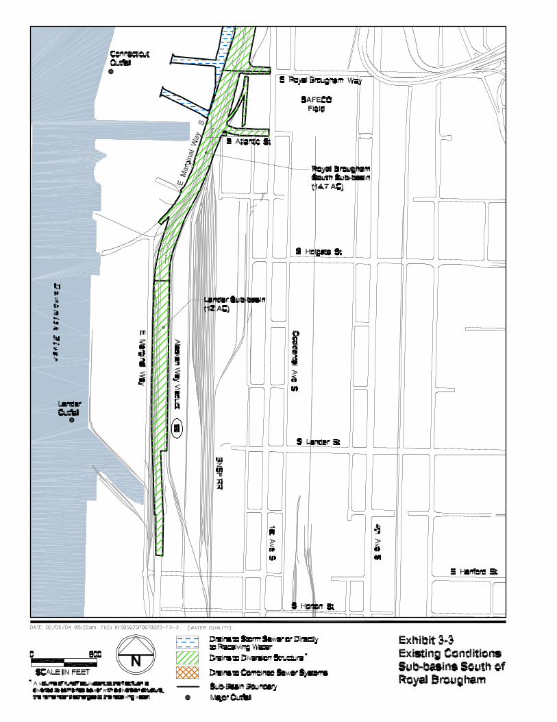
A total of 20 sub-basins were delineated in the project area and primarily include the existing viaduct and Alaskan Way surface street. It was assumed that the entire sub-basin is PGIS. Exhibit 1-1 summarizes sub-basin areas in each geographic location and the area of PGIS redeveloped under each alternative. The total sub-basin area remains the same for each alternative.

SR 99: Alaskan Way Viaduct & Seawall Replacement Project March 2004 Water Resources Discipline Report 2 Draft EIS
Exhibit 1-1. PGIS Area (Acres) for Geographic Areas Alternative
Geographic Area1,2 Existing
Sub-basin3 Rebuild Aerial Tunnel Bypass Tunnel Surface
South of S. Royal Brougham Way
26.7 20.5 12.0 20.5 20.5 20.6
Central Business District 59.7 45.8 35.5 45.5 47.9 46.2
North of Vine Street 14.3 1.7 6.2 6.2 6.2 8.2
Total 97.9 68.0 53.7 72.2 74.6 75.0 1 Refer to Exhibits 3-3, 3-4, and 3-5 for the sub-basins located in each geographic area. Sub-basin areas are presented in Exhibit B-2. 2 Areas are not presented by receiving water because each sub-basin has multiple receiving waters as discussed in Chapter 4, Methodology. 3 Sub-basins were delineated for use in this analysis and are inclusive of all proposed project alternatives; therefore, the existing sub-basin area is larger than the area of PGIS replaced under each alternative.
1.2 Summary of Water Quality Evaluation Methods and Assumptions The five AWV Build Alternatives and two approaches for managing stormwater runoff from the project area were evaluated by comparing the calculated annual pollutant load that will be discharged to the environment. Alternatives and approaches were compared to each other and to existing conditions. Potential impacts to water quality were evaluated for total suspended solids (TSS), total copper (Cu), and total zinc (Zn) because (1) they are pollutants commonly associated with highway runoff, (2) data are available for the concentration of these pollutants in runoff and for treatment removal efficiency, and (3) because these pollutants are regulated by state standards. Documentation for the selection of pollutants of potential concern can be found in Attachment C. The five Build Alternatives are described in detail in Appendix B, Alternatives Description and Construction Methods Technical Memorandum. For the purposes of this analysis, it was assumed that the Rebuild, Aerial, and Tunnel Alternatives will implement the BMP Approach for stormwater management and the Bypass Tunnel and Surface Alternatives will implement the Convey and Treat Approach for stormwater management. The two approaches to stormwater management only differ in the Central Business District. In addition, at this stage in design, either of the stormwater management approaches could be used with any of the Build Alternatives.
A mass balance model was developed to compare existing conditions with the BMP and Convey and Treat Approaches for managing stormwater runoff. In general, the model is based on the following concept:
(Annual Pollutant Load) – (Treatment Removal) = Annual Load to the Environment

SR 99: Alaskan Way Viaduct & Seawall Replacement Project March 2004 Water Resources Discipline Report 3 Draft EIS
Annual pollutant load was calculated for TSS, Zn, and Cu using “Method 3: FHWA” in the Washington State Department of Transportation (WSDOT) Water Resources Discipline Study Guidance Document (WSDOT 2002b). The mass balance model method relies on:
• Differences in PGIS. • Differences in treatment removal. • Differences in discharge location.
Under each proposed alternative, project area stormwater will be treated using one or more of the following methods: Stormwater BMPs, the West Point Treatment Plant (TP), or the proposed Royal Brougham TP. Each treatment method differs in the removal efficiency and percent of the annual volume treated.
1.3 Water and Sediment Quality Concerns The Duwamish River (Segment 421), Elliott Bay, Puget Sound, and Lake Union are the main waterbodies within the project area. Based on the Washington State Department of Ecology (Ecology) 303(d) List, the parameters of concern in the water column are:
• Duwamish River – None • Elliott Bay – Fecal Coliform • Puget Sound - None • Lake Union – None
In addition, Duwamish River, Elliott Bay, and Puget Sound are listed on the Ecology 303(d) List1 of Threatened and Impaired Waterbodies for exceedance of Sediment Management Standards WAC 173-204 (Ecology 1995c) and Lake Union is listed as having failed the sediment bioassay. There are no Washington State Sediment Management Standards for chemical levels in freshwater sediment. In lieu of regulatory levels, sediment samples from the south end of Lake Union were compared to proposed levels from three freshwater studies. See Chapter 3, Affected Environment and Attachment F for more detail. As discussed in Chapter 3, the project area has been developed for over 100 years, and there are numerous sources of pollutants.
1 Section 303(d) of the federal Clean Water Act requires Washington State periodically to prepare a list of all surface waters in the state for which beneficial uses of the water—such as for drinking, recreation, aquatic habitat, and industrial use—are impaired by pollutants. These are water quality limited estuaries, lakes, and streams that fall short of state surface water quality standards and are not expected to improve within the next 2 years. This list is currently being updated for 2004. This section will be revised when the 2004 303(d) list is finalized.

SR 99: Alaskan Way Viaduct & Seawall Replacement Project March 2004 Water Resources Discipline Report 4 Draft EIS
1.4 Impact Summary
1.4.1 Operational Impacts
All of the proposed Build Alternatives will improve the quality of runoff from the project area discharged to the environment as compared to existing conditions (Exhibit 1-2). Based on the mass balance analysis, the Rebuild Alternative will provide the greatest reduction in TSS, Zn, and Cu loading. However, all of the alternatives are similar, and differences between the alternatives may be partially accounted for by variability in the assumptions used to calculate the pollutant loads. The assumptions made for removal efficiency for the different treatment methods, as well as the actual volumes treated, were based on conservative estimates of likely values. However, these values are variable depending on design, maintenance, operation, and storm events.
Exhibit 1-2. Summary of Annual Water Quality Loading (Pounds per Year)
Alternative
BMP Approach Convey and Treat
Approach
Pollutant1 Existing
Conditions2 Rebuild Aerial Tunnel Bypass Tunnel Surface
TSS 10,900 6,000 8,000 6,000 6,000 6,000 Duwamish River Zn 16 10 13 10 10 10
Cu 3 2 3 2 2 2
Elliott Bay TSS 72,000 35,300 47,300 36,700 37,900 40,000
Zn 107 63 77 65 62 64
Cu 21 13 16 14 13 13
Puget Sound TSS 3,100 3,100 3,100 3,100 6,000 6,100
Zn 7 7 7 7 13 13
Cu 1 1 1 1 2 2
Lake Union3 TSS 1,300 1,300 600 600 600 300
Zn 2 2 1 1 1 0
Cu 0 0 0 0 0 0
TSS 87,300 45,700 59,000 46,400 50,500 52,400
Zn 132 82 98 83 86 87
Total Combined Load
Cu 26 17 20 17 17 17 1 Total Suspended Solids (TSS) rounded to the nearest 100 pounds, Zinc (Zn) and Copper (Cu) rounded to the nearest tenth of a pound. 2 The No Build Alternative is the same as Existing Conditions. 3 The Rebuild Alternative is the same as Existing Conditions in this basin.
SR 99: Alaskan Way Viaduct & Seawall Replacement Project March 2004 Water Resources Discipline Report 5 Draft EIS
1.4.2 Construction Impacts
Construction activities such as in-water work, dewatering, and grading could have temporary water quality impacts. In-water work will be required under all of the proposed Build Alternatives to remove the existing seawall and construct an over-water structure between Pier 48 and Colman Dock to provide ferry access. In addition, the Tunnel and Bypass Tunnel Alternatives will require additional in-water work to construct a tunnel waterward of the existing seawall in the vicinity of Colman Dock and extend the storm drain and CSO outfall at Washington Street. It is likely that BMPs will be implemented to isolate the work area from receiving waters, which will minimize or prevent temporary impacts. Dewatering will also be required for the Tunnel and Bypass Tunnel Alternatives. Dewatering water, which may contain sediment and/or other contaminants, will be treated as necessary to minimize or prevent impacts to the receiving water. Grading could also have temporary impacts on water quality if sediment or other contaminants from a disturbed area are discharged to receiving waters. However, for all of the cases noted above, water treatment and/or other measures are planned to mitigate these impacts (see Section 1.5.2 and Chapter 9, Construction Mitigation).
1.5 Mitigation Summary
1.5.1 Operational Mitigation
Because all of the proposed Build Alternatives will result in an overall improvement in water quality as compared to existing conditions, no mitigation is proposed for the operation of the project, though the code and regulatory requirements will be undertaken as part of the project.
1.5.2 Construction Mitigation
Temporary sediment and erosion control BMPs will be implemented in accordance with the Ecology Stormwater Management Manual for Western Washington (Ecology manual) (Ecology 2001). In locations where in-water work will occur sediment barriers could be used to minimize the possibility of fine material being transported through joints in the existing seawall. All effluent during construction will be inspected as per the Temporary Erosion and Sediment Control (TESC) Plan developed for the project. In addition, a Spill Control and Countermeasures Plan and a Surface Water Pollution Prevention Plan will be developed for the site during the permitting and design phases.
SR 99: Alaskan Way Viaduct & Seawall Replacement Project March 2004 Water Resources Discipline Report 6 Draft EIS
1.6 Compliance With Surface Water-Related Plans and Policies In general, the proposed BMP and Convey and Treat Approaches will comply with most of the applicable federal, state, and local surface water related plans and policies.
The BMP approach will treat stormwater runoff from the project area using the revised WSDOT Highway Runoff Manual, which will be equivalent with the Ecology manual or detain runoff prior to discharge to the combined sewer system. The Ecology manual (and any equivalent manual) represents all known and reasonable technology (AKART) for water quality treatment and the Ecology manual is based on a presumptive approach to stormwater management. Therefore, the stormwater BMPs (which are equivalent to AKART) will be designed and implemented in accordance with the design guidance in the manual. The BMP Approach is also based on the City of Seattle Stormwater Management Manual (Seattle 2001b).
The Convey and Treat Approach will collect approximately 38 million gallons per year (MG/yr) of stormwater runoff that is currently separated from the combined sewer system and convey it to the combined sewer system (see Figure 4-11). Adding new stormwater into the combined sewer system will require concurrence among various permitting agencies.
Additional information about the applicable regulations is found in Chapter 10, Permits and Approvals.

SR 99: Alaskan Way Viaduct & Seawall Replacement Project March 2004 Water Resources Discipline Report 7 Draft EIS
Chapter 2 STUDIES AND COORDINATION This report was prepared using information collected from Ecology and National Oceanic and Atmospheric Administration (NOAA) studies and coordination with WSDOT, the City of Seattle, and King County DNR.
WSDOT provided information about pollutant concentrations common in stormwater runoff and information about water quality treatment BMP pollutant removal efficiencies (Ecology 2001; WSDOT 2002b).
The City of Seattle attended several coordination meetings to document and map the existing combined sewer and stormwater drainage systems. Information provided by the City included Geographic Information System (GIS) maps of the drainage system, Side Sewer Cards, National Pollutant Discharge Elimination System (NPDES) combined sewer overflow (CSO) data, and CSO Reduction Plans (Metro 1988a). Information about specific drainage basin boundaries within the project area was not provided. The main City contacts were Elizabeth Anderson, Bob Chandler, and Neil Thibert.
King County DNR also attended several coordination meetings to document and map the existing combined sewer system. The County provided information about the function of diversion structures, areas served by separated storm systems, and CSO data, as well as constituents common in combined sewage and the removal efficiency of the West Point TP and Denny Way CSO Treatment Facility. The main County contacts were Karen Huber, Bob Swarner, and Eric Davison.
Information about existing water quality was collected primarily from Ecology using the 303(d) List of Threatened and Impaired Waterbodies, Total Maximum Daily Loads (TMDLs), and Water Resource Inventory Area (WRIA) studies found on the internet, and NPDES CSO outfall water quality monitoring data found in the Elliott Bay Recontamination Study (Ecology 1995a. Information about BMP treatment removal efficiencies was also collected from Ecology.

This Page Intentionally Left Blank

SR 99: Alaskan Way Viaduct & Seawall Replacement Project March 2004 Water Resources Discipline Report 9 Draft EIS
Chapter 3 AFFECTED ENVIRONMENT
3.1 Affected Environment Methods Pertinent historical water quality and sediment information used to characterize the affected environment was obtained by reviewing existing literature found through searches of standard literature databases (Aquatic Sciences and Fisheries Abstracts, Current Contents), library catalogs (University of Washington), Web searches, agency coordination, and NOAA’s Elliott Bay/Duwamish River Natural Resource Damage Assessment and Restoration Planning website. The relevant information was then reviewed and summarized.
Because the project is located adjacent to a marine waterbody and Lake Union,2 no floodplains were identified and no changes to the hydrology of the receiving waters will occur. Therefore, these two elements of the affected environment were not characterized.
3.2 Affected Environment Introduction The existing Alaskan Way Viaduct and Seawall Replacement Project area is part of the highly developed downtown urban corridor along the Elliott Bay waterfront (Exhibit 3-1). The project area has been developed for over 100 years and is assumed to be 100 percent impervious. Development and associated activities have degraded the water quality and nearshore sediments of receiving waterbodies surrounding the project area, including Elliott Bay, the Duwamish River, Puget Sound, and Lake Union. Specific sources of pollutants in the project area include discharges from industrial facilities, CSOs, spills, contaminated groundwater, and urban storm drains (Ecology 1995b).
Historically, a combined sewer system was built in Seattle to collect both sanitary sewage and stormwater in a single pipe and convey it to a discharge location. In the early 1960s, Metro was formed and prepared the Comprehensive Sewer Plan and work began to reduce the annual volume of untreated sanitary and combined sewage discharge to surface waters in King County.
2 The water surface elevation of Lake Union is controlled by the Army Corps of Engineers at the Hiram M. Chittenden Locks.

Puget
Sound
WestPoint
Broad
St
Denny Way
LakeUnion
ElliottBay
Queen A
nne Ave N
Mercer St
Alaskan Way
Batte
ry S
t
Pike St
90
Alaskan Way Viaduct
Stewar
t St
Duw
amish River
APPROXIMATE LIMITOF ELLIOTT BAY
APPROXIMATE LIMITOF DUWAMISH RIVER1
1st Ave
Yesler Way
Seneca St
Columbia St
4th Ave
King St
5
99
1st Ave S
4th Ave S
S Holgate St
S Royal Brougham Way
S Lander St
E M
arginal Way S
S Spokane St
Approximate Project Corridor
Duwamish River Mouth at line bearing 254° truefrom the NWcorner of berth, Terminal No. 37(Ecology 2003)
554-1585-025/06(0620) 9/03 (K)
N Exhibit 3-1Project Location Map
0 2,500
SCALE IN FEET
1

SR 99: Alaskan Way Viaduct & Seawall Replacement Project March 2004 Water Resources Discipline Report 11 Draft EIS
As part of this program, the City and Metro constructed several projects within the project area that have reduced the frequency and volume of remaining CSOs (Metro 1988a). The goal of these projects and others outlined in the 1988 CSO Control Plan is to reduce the total untreated CSO volume by 76 percent by the year 2006 (Metro 1988a). In addition, Seattle produced a CSO control plan in 1988 and an update in 2001 and has had an active CSO reduction plan since the 1970s.
The project area covers approximately 98 acres, and runoff from the project area drains to 20 sub-basins (Exhibits 3-3, 3-4, and 3-5). The sub-basins shown on Exhibits 3-3, 3-4, and 3-5 are inclusive of all the alternatives; however, the proposed footprint and corresponding area of PGIS associated with each alternative varies within the sub-basins. In general, these sub-basins are part of larger complex basins that drain most of Seattle (Exhibit 3-2). Most of the stormwater runoff from the central and north waterfront sections of the project area discharges to Elliott Bay. Runoff from other portions of the project area discharges to the Duwamish River, Puget Sound, and Lake Union (Exhibits 3-3, 3-4, and 3-5).
Stormwater from the project area is currently collected in a complex system of pipes, which is part of the historical combined sewer system. These pipes are local, privately owned pipes or owned by either King County DNR or the City of Seattle. These pipes do one of three things:
1. They collect stormwater from the existing viaduct and convey it to a stormwater-only outfall, where it is discharged with minimal treatment.
2. They collect stormwater and convey it to the City’s combined sewer system, and then on to the County’s combined system and the West Point Treatment Plant.
3. They collect stormwater and convey it to a diversion structure where flows will either be diverted to the County’s combined sewer system or discharge directly to Elliott Bay or the Duwamish River.
Sub-basin type is defined based on how runoff from the viaduct and Alaskan Way surface street is collected and conveyed to the receiving water (Exhibit 3-6). Storm only sub-basins are sub-basins where stormwater runoff from the project area is collected in a stormwater-only drainage system and discharged to the receiving water. Diversion structure sub-basins are sub-basins where stormwater runoff from the project area is collected in a stormwater-only

This Page Intentionally Left Blank

Exhibit 3-2City of Seattle Stormwater andCombined Sewer Basins
PC
: Ala
skan
Way
Via
duct
554
-158
5-02
5/06
(063
) 3/0
4 (K
)

This Page Intentionally Left Blank

This Page Intentionally Left Blank


This Page Intentionally Left Blank

This Page Intentionally Left Blank

SR 99: Alaskan Way Viaduct & Seawall Replacement Project March 2004 Water Resources Discipline Report 21 Draft EIS
Exhibit 3-6. Existing Project Sub-basin Areas and Receiving Water Receiving
Water/ Sub-basin
Sub-basin Area
(Acres) Outfall Type Outfall Owner
Project Basin Type
Existing Water Quality Treatment
Duwamish River Lander 12.0 Shared City Stormwater/
County CSO Diversion Structure
Low-Flow Diversion1
Elliott Bay Royal Br ougham South
14.7 Shared City Stormwater/ County CSO
Diversion Structure
Minimal
Royal Brougham North
8.4 Shared City Stormwater/ County CSO
Diversion Structure
Minimal
Washington 5.0 Storm City Storm Only Minimal T46 13.4 Storm Unknown Storm Only Minimal Madison 6.0 Shared City Storm Only Minimal S1 1.9 Storm City Storm Only Minimal S2 4.2 Storm City Storm Only Minimal Seneca 0.5 Storm City Storm Only Minimal University 3.1 Shared City Storm Only Minimal S3 2.6 Storm City Storm Only Minimal Pine 3.0 Storm City Storm Only Minimal S4 0.8 Storm City Storm Only Minimal S5 0.8 Storm City Storm Only Minimal Sub-Total Area 64.4 Puget Sound King2 5.0 CSO City Combined West Point TP Pike 2.1 None N.A. Combined West Point TP Vine 2 4.8 CSO City Combined West Point TP Denny2 4.1 CSO County Combined West Point TP Lake Union West3 4.2 CSO County Combined West Point TP Sub-Total Area 20.2 Lake Union Broad 1.2 Storm City Storm Only Minimal Project Total Area 97.8
1 Low flow diversions are structures constructed within the drainage system that divert a volume of runoff equivalent to the first flush to the combined sewer system and divert the remaining volume to an outfall for direct discharge. For this analysis, it was assumed that the first flush is equivalent to 10 percent of the annual flow volume. 2 Puget Sound is the receiving water during normal operating conditions. During CSO events, runoff will discharge to Elliott Bay as a CSO. 3 Puget Sound is the receiving water during normal operating conditions. During CSO events, runoff will be routed to the new Denny Tunnel and will discharge to Elliott Bay as a treated CSO at Denny. During extreme events, runoff will discharge to Lake Union as a CSO.
SR 99: Alaskan Way Viaduct & Seawall Replacement Project March 2004 Water Resources Discipline Report 22 Draft EIS
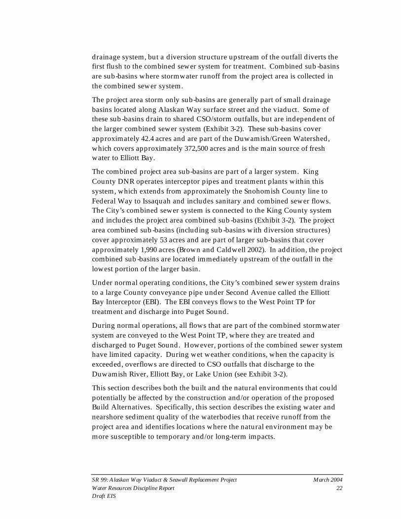
drainage system, but a diversion structure upstream of the outfall diverts the first flush to the combined sewer system for treatment. Combined sub-basins are sub-basins where stormwater runoff from the project area is collected in the combined sewer system.
The project area storm only sub-basins are generally part of small drainage basins located along Alaskan Way surface street and the viaduct. Some of these sub-basins drain to shared CSO/storm outfalls, but are independent of the larger combined sewer system (Exhibit 3-2). These sub-basins cover approximately 42.4 acres and are part of the Duwamish/Green Watershed, which covers approximately 372,500 acres and is the main source of fresh water to Elliott Bay.
The combined project area sub-basins are part of a larger system. King County DNR operates interceptor pipes and treatment plants within this system, which extends from approximately the Snohomish County line to Federal Way to Issaquah and includes sanitary and combined sewer flows. The City’s combined sewer system is connected to the King County system and includes the project area combined sub-basins (Exhibit 3-2). The project area combined sub-basins (including sub-basins with diversion structures) cover approximately 53 acres and are part of larger sub-basins that cover approximately 1,990 acres (Brown and Caldwell 2002). In addition, the project combined sub-basins are located immediately upstream of the outfall in the lowest portion of the larger basin.
Under normal operating conditions, the City’s combined sewer system drains to a large County conveyance pipe under Second Avenue called the Elliott Bay Interceptor (EBI). The EBI conveys flows to the West Point TP for treatment and discharge into Puget Sound.
During normal operations, all flows that are part of the combined stormwater system are conveyed to the West Point TP, where they are treated and discharged to Puget Sound. However, portions of the combined sewer system have limited capacity. During wet weather conditions, when the capacity is exceeded, overflows are directed to CSO outfalls that discharge to the Duwamish River, Elliott Bay, or Lake Union (see Exhibit 3-2).
This section describes both the built and the natural environments that could potentially be affected by the construction and/or operation of the proposed Build Alternatives. Specifically, this section describes the existing water and nearshore sediment quality of the waterbodies that receive runoff from the project area and identifies locations where the natural environment may be more susceptible to temporary and/or long-term impacts.
SR 99: Alaskan Way Viaduct & Seawall Replacement Project March 2004 Water Resources Discipline Report 23 Draft EIS
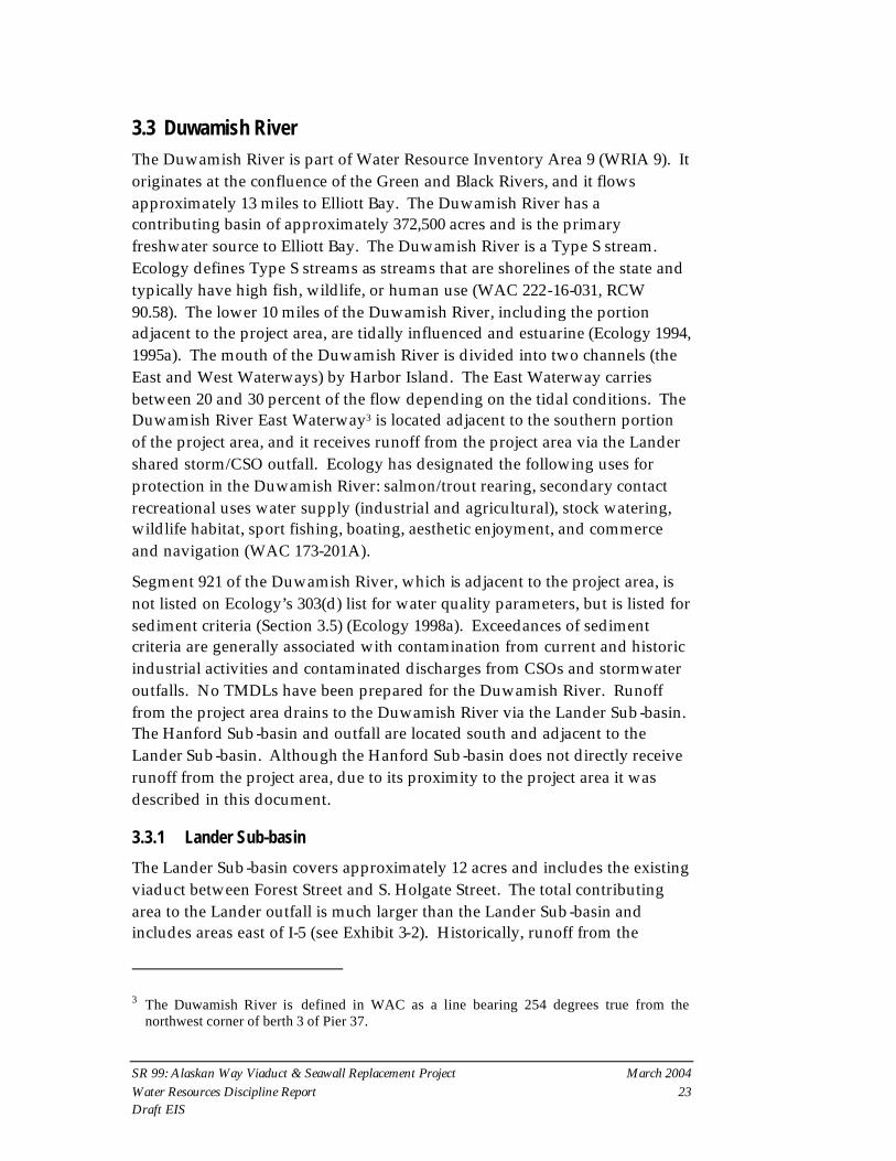
3.3 Duwamish River The Duwamish River is part of Water Resource Inventory Area 9 (WRIA 9). It originates at the confluence of the Green and Black Rivers, and it flows approximately 13 miles to Elliott Bay. The Duwamish River has a contributing basin of approximately 372,500 acres and is the primary freshwater source to Elliott Bay. The Duwamish River is a Type S stream. Ecology defines Type S streams as streams that are shorelines of the state and typically have high fish, wildlife, or human use (WAC 222-16-031, RCW 90.58). The lower 10 miles of the Duwamish River, including the portion adjacent to the project area, are tidally influenced and estuarine (Ecology 1994, 1995a). The mouth of the Duwamish River is divided into two channels (the East and West Waterways) by Harbor Island. The East Waterway carries between 20 and 30 percent of the flow depending on the tidal conditions. The Duwamish River East Waterway3 is located adjacent to the southern portion of the project area, and it receives runoff from the project area via the Lander shared storm/CSO outfall. Ecology has designated the following uses for protection in the Duwamish River: salmon/trout rearing, secondary contact recreational uses water supply (industrial and agricultural), stock watering, wildlife habitat, sport fishing, boating, aesthetic enjoyment, and commerce and navigation (WAC 173-201A).
Segment 921 of the Duwamish River, which is adjacent to the project area, is not listed on Ecology’s 303(d) list for water quality parameters, but is listed for sediment criteria (Section 3.5) (Ecology 1998a). Exceedances of sediment criteria are generally associated with contamination from current and historic industrial activities and contaminated discharges from CSOs and stormwater outfalls. No TMDLs have been prepared for the Duwamish River. Runoff from the project area drains to the Duwamish River via the Lander Sub-basin. The Hanford Sub-basin and outfall are located south and adjacent to the Lander Sub-basin. Although the Hanford Sub-basin does not directly receive runoff from the project area, due to its proximity to the project area it was described in this document.
3.3.1 Lander Sub-basin
The Lander Sub-basin covers approximately 12 acres and includes the existing viaduct between Forest Street and S. Holgate Street. The total contributing area to the Lander outfall is much larger than the Lander Sub-basin and includes areas east of I-5 (see Exhibit 3-2). Historically, runoff from the
3 The Duwamish River is defined in WAC as a line bearing 254 degrees true from the northwest corner of berth 3 of Pier 37.

SR 99: Alaskan Way Viaduct & Seawall Replacement Project March 2004 Water Resources Discipline Report 24 Draft EIS
Lander Sub-basin was collected in the combined sewer system. The Lander/Bayview Separation project was completed in the late 1980s to reduce overflows at this outfall by separating stormwater runoff from the Lander Sub-basin (and other areas) from the combined sewer system, creating a new combined line and a parallel stormwater-only system (Ecology 1994). Currently, stormwater runoff in the Lander Sub-basin flows through a diversion structure, which diverts a volume of stormwater runoff equivalent to the first flush to the combined sewer system for treatment and discharge at the West Point TP. King County DNR manages the Lander outfall as a shared stormwater/CSO for the combined sewer system (Exhibit 3-7).
Exhibit 3-7. CSO Discharges to the Duwamish River (East Waterway in the Project Vicinity) (King County 2003)
Hanford1 Outfall Lander Outfall
Study Period Frequency
(Events/Year)
Volume (Million Gallons/
Year) Frequency
(Events/Year)
Volume (Million Gallons/
Year)
1983 Baseline2 23 266 22 143
19992 15 210 12 100
20052 15 223 12 100 1 Modeled data is for King County Hanford #2 system. 2 Based on historical CSO events and modeling (King County 2000).
3.4 Elliott Bay Elliott Bay makes up the eastern portion of central Puget Sound and is an estuary (Ecology 1994). The shallow nearshore is adjacent to the AWV project area is and where the outfalls discharge. A more detailed description of the nearshore environment of Elliott Bay is provided in Appendix R, Fisheries, Wildlife, and Habitat Discipline Report.
The Duwamish River flows into the southern portion of Elliott Bay and is the primary source of fresh water to Elliott Bay. Residence time of fresh water in the Inner Harbor varies from 1 to 10 days depending on weather. Based on the results of numerous studies, estuarine water in Elliott Bay generally circulates counter-clockwise. Fresh water enters from the Duwamish, moves north along the Inner Harbor, and then flows out to Puget Sound (Ecology 1995b; URS and Evans-Hamilton 1986). Water currents in the Inner Harbor are generally low, and velocities are typically oriented parallel to the faces of downtown waterfront piers (Sillcox et al. 1981).
Ecology has designated Elliott Bay as an excellent waterbody for aquatic life uses and primary contact recreational uses. Ecology has also designated the following uses for protection: shellfish harvesting, wildlife habitat, sport

SR 99: Alaskan Way Viaduct & Seawall Replacement Project March 2004 Water Resources Discipline Report 25 Draft EIS
fishing, boating, aesthetic enjoyment, and commerce and navigation. Elliott Bay has been listed on the 1998 Ecology 303(d) List of Impaired and Threatened Waterbodies for exceeding fecal coliform criteria near the Denny Way CSO outfall. No TMDLs for pollutants of concern have been prepared for Elliott Bay. In addition, Elliott Bay has also exceeded numerous sediment criteria, which are discussed in Section 3.7.2, Nearshore Sediments.
Stormwater runoff from the central project area drains to Elliott Bay via City stormwater outfalls or City Stormwater/County CSO shared outfalls (Exhibit 3-4). These outfalls drain the Royal Brougham, Washington, Madison, Seneca, University, and Pine Sub-basins. In addition, stormwater from the “S” Sub-basins and the T46 Sub-basin drain directly to Elliott Bay via catch basins and/or small pipes in the seawall.
3.4.1 Royal Brougham Sub-basin
The project area is located in two Royal Brougham sub-basins, Royal Brougham South (14.7 acres) and Royal Brougham North (8.4 acres), which are located between S. Holgate Street and Railroad Way S. Stormwater runoff in these sub-basins flows through a diversion structure, which diverts a volume of stormwater runoff equivalent to the first flush to the combined sewer system for treatment and discharge at the West Point TP. The remainder of the stormwater is conveyed to the shared City stormwater/County CSO 72-inch Connecticut outfall, where it is discharged with minimal treatment.
King County DNR operates the Kingdome (Royal Brougham) regulator as part of the EBI system and regulates CSO events that occur at this outfall. Exhibit 3-8 shows the frequency and volume of recorded CSO events at the shared Connecticut outfall. King County DNR plans to construct a new CSO treatment plant at Royal Brougham by the year 2026. This plant is intended to treat CSOs from the Royal Brougham and King Basins.
Exhibit 3-8. King County DNR CSO Discharges to Elliott Bay (King County 2003) Royal Brougham Outfall King Outfall Denny Outfall
Study Period Frequency (events/yr)
Volume (MG/yr) Frequency
Volume (MG/yr) Frequency
Volume (MG/yr)
1983 Baseline1 29 90 14 55 25 502
19991 10 79 14 38 24 449
20051 10 70 14 38 1 8 MG/yr = million gallons per year 1 Based on historical CSO events and modeling (King County 2000).
SR 99: Alaskan Way Viaduct & Seawall Replacement Project March 2004 Water Resources Discipline Report 26 Draft EIS
In addition to the Royal Brougham CSO, King County operates the King and Denny CSOs, which receive runoff from the project and also drain to Elliott Bay. These CSOs are discussed later in the Puget Sound section (Section 3.5).
3.4.2 Washington Sub-basin
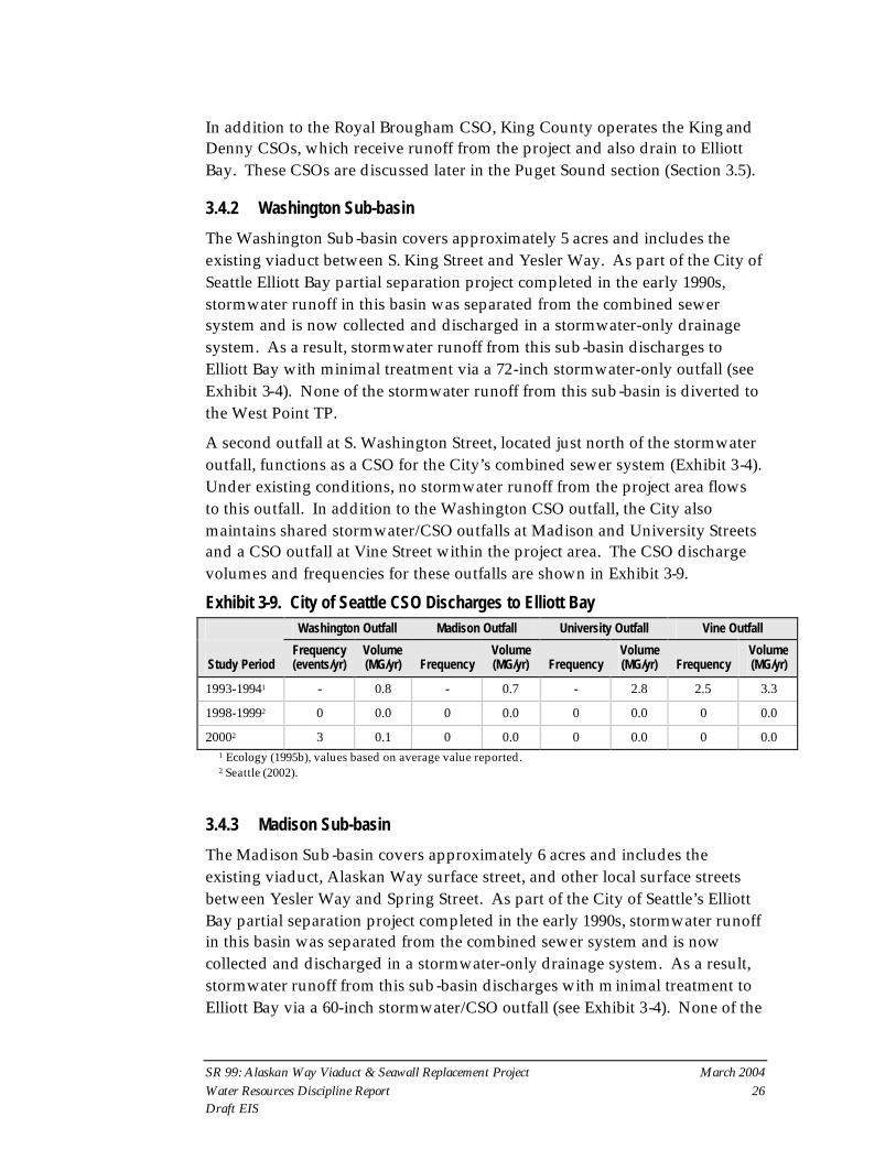
The Washington Sub-basin covers approximately 5 acres and includes the existing viaduct between S. King Street and Yesler Way. As part of the City of Seattle Elliott Bay partial separation project completed in the early 1990s, stormwater runoff in this basin was separated from the combined sewer system and is now collected and discharged in a stormwater-only drainage system. As a result, stormwater runoff from this sub-basin discharges to Elliott Bay with minimal treatment via a 72-inch stormwater-only outfall (see Exhibit 3-4). None of the stormwater runoff from this sub-basin is diverted to the West Point TP.
A second outfall at S. Washington Street, located just north of the stormwater outfall, functions as a CSO for the City’s combined sewer system (Exhibit 3-4). Under existing conditions, no stormwater runoff from the project area flows to this outfall. In addition to the Washington CSO outfall, the City also maintains shared stormwater/CSO outfalls at Madison and University Streets and a CSO outfall at Vine Street within the project area. The CSO discharge volumes and frequencies for these outfalls are shown in Exhibit 3-9.
Exhibit 3-9. City of Seattle CSO Discharges to Elliott Bay Washington Outfall Madison Outfall University Outfall Vine Outfall
Study Period Frequency (events/yr)
Volume (MG/yr) Frequency
Volume (MG/yr) Frequency
Volume (MG/yr) Frequency
Volume (MG/yr)
1993-19941 - 0.8 - 0.7 - 2.8 2.5 3.3
1998-19992 0 0.0 0 0.0 0 0.0 0 0.0
20002 3 0.1 0 0.0 0 0.0 0 0.0 1 Ecology (1995b), values based on average value reported. 2 Seattle (2002).
3.4.3 Madison Sub-basin
The Madison Sub-basin covers approximately 6 acres and includes the existing viaduct, Alaskan Way surface street, and other local surface streets between Yesler Way and Spring Street. As part of the City of Seattle’s Elliott Bay partial separation project completed in the early 1990s, stormwater runoff in this basin was separated from the combined sewer system and is now collected and discharged in a stormwater-only drainage system. As a result, stormwater runoff from this sub-basin discharges with minimal treatment to Elliott Bay via a 60-inch stormwater/CSO outfall (see Exhibit 3-4). None of the

SR 99: Alaskan Way Viaduct & Seawall Replacement Project March 2004 Water Resources Discipline Report 27 Draft EIS
stormwater runoff from this sub-basin is diverted to the West Point TP. This outfall is also a City CSO, though no CSOs have been reported since 1995 (Exhibit 3-9).
3.4.4 Seneca Sub-basin
The Seneca Sub -basin is a 0.5-acre area located between Spring Street and University Street along the waterfront. Stormwater runoff from this sub-basin discharges with minimal treatment to Elliott Bay via a 10-inch stormwater outfall. None of the stormwater runoff from this sub-basin is diverted to the West Point TP.
3.4.5 University Sub-basin
The University Sub-basin is located in the central portion of downtown and drains approximately 3.1 acres. Approximately 1.7 to 2.9 acres (depending on the alternative) of the existing viaduct and Alaskan Way surface street between Union and University Streets drain to this sub-basin. Stormwater runoff in this basin was separated from the combined sewer system as part of the City’s Elliott Bay partial separation project completed in the early 1990s. As a result, stormwater is now collected and discharged in a stormwater-only drainage system. Therefore, stormwater runoff from this sub-basin discharges with minimal treatment to Elliott Bay via a 24-inch shared stormwater/CSO outfall with a drop structure built into the seawall at University Street. None of the stormwater runoff from this sub-basin is diverted to the West Point TP. Although this outfall serves as a City CSO, no CSOs have been reported since 1995 (Exhibit 3-9).
3.4.6 Pine Sub-basin
The Pine Sub-basin, approximately 3.0 acres, is located between Pike Street and Lenora Street. The existing viaduct and local surface streets make up the majority of land use in this sub-basin. Stormwater runoff from this sub-basin discharges with minimal treatment to Elliott Bay via a 16-inch stormwater outfall. None of the stormwater runoff from this sub-basin is diverted to the West Point TP.
3.4.7 “S” Sub-basins
There are five small sub-basins, totaling 15.9 acres, where minimally treated runoff from the existing Alaskan Way surface street drains directly to Elliott Bay via a system of catch basins and small pipes and cracks in the existing seawall (Exhibit 3-10).

SR 99: Alaskan Way Viaduct & Seawall Replacement Project March 2004 Water Resources Discipline Report 28 Draft EIS
Exhibit 3-10. Summary of “S” Sub-basins Sub-basin Name Area (Acres) Corresponding Streets
S1 1.9 Clay and Bay
S2 4.2 Lenora and Clay
S3 2.6 Pike and Lenora
S4 0.8 University and Pike
S5 0.8 Madison and University
The sub-basins are located between approximately Bay and University Streets along the Alaskan Way surface street.
3.4.8 T46 Sub-basin
The T46 Sub-basin is located on Terminal 46 and covers approximately 13.4 acres. Under existing conditions, there is no formal drainage system in place, and it was assumed that runoff discharges untreated directly to Elliott Bay via catch basins or holes in the over-water structure.
3.5 Puget Sound Puget Sound is a large marine waterbody that covers approximately 900 square miles, including Elliott Bay. Other than Elliott Bay, Puget Sound has not been listed on Ecology’s 303(d) list. In the project area, Ecology has designated the same uses for protection as Elliott Bay (WAC 173-201A). No TMDLs have been prepared for Puget Sound in the vicinity of the project area.
Under normal operating conditions, which include small storms, stormwater runoff from the King, Pike, Vine, Denny, and West Lake Union Sub-basins is collected in combined sewer pipes and discharged to Puget Sound as treated combined stormwater at the West Point TP deep water outfall. Treatment at the West Point TP includes settling and disinfection. During large storm events, when the combined sewer capacity is exceeded, untreated CSO events occur at numerous locations within the system, including outfalls located along the Duwamish East Waterway and Elliott Bay waterfront. In addition, treated events will occur at the Denny outfall once the Denny Way CSO Treatment Facility is online in 2005. Construction is underway for a joint King County/City project that will divert combined flows from the County’s Dexter outfall, as well as other City Lake Union CSOs, to the Denny system. This project will construct a CSO storage facility to provide additional capacity. This project is expected to be operational in 2005 and was assumed to be an existing condition for this analysis.

SR 99: Alaskan Way Viaduct & Seawall Replacement Project March 2004 Water Resources Discipline Report 29 Draft EIS
3.5.1 King Sub-basin
The King Sub-basin is approximately 5.0 acres and includes the existing viaduct between Railroad Way S. and S. King Street. The King Sub-basin is part of a larger basin that extends east of I-5 (see Exhibit 3-2) (Brown and Caldwell 2002). Stormwater runoff in this sub-basin is collected in separated storm pipes; however, they connect to the combined sewer system upstream of a diversion structure. Therefore, under normal operating conditions, stormwater runoff from this basin is diverted to the EBI and is conveyed to the West Point TP for treatment and discharged to Puget Sound. During large storm events, combined stormwater runoff is discharged in a 48-inch pipe to Elliott Bay as an untreated CSO (Exhibit 3-4).
3.5.2 Pike Sub-basin
The Pike Sub-basin covers approximately 2.1 acres in the central portion of the project area. Runoff from this sub-basin is collected in combined sewer pipes and conveyed to the Pike Street “ADIT” structure. The ADIT structure is a vault with an 18-inch pipe that regulates the volume of flow diverted to the EBI. During normal operations, stormwater runoff from this sub-basin is collected in the combined system and conveyed to the West Point TP for treatment and discharged to Puget Sound. Because there is no outfall associated with this sub-basin, during large storm events, the system backups and flows are discharged as untreated CSOs at other City CSOs in the project area.
3.5.3 Vine Sub-basin
The Vine Sub-basin covers approximately 4.8 acres in the northern portion of the project area. Within this sub-basin, the existing viaduct is primarily located in the Battery Street Tunnel. However, stormwater runoff from surface streets and the portion of the viaduct exposed to rain is collected in the combined system. During normal operations, stormwater runoff from this sub-basin will be collected in a combined stormwater system and will be conveyed to the West Point TP for treatment and discharged to Puget Sound. During large storm events, flows will either discharge at Denny Way after being treated at the Denny Way CSO Treatment Facility or discharge via the City’s 24-inch Vine Street outfall as an untreated CSO. Although the City has not reported any overflows at this outfall, Ecology reported that approximately 3.3 MG per year were discharged from the outfall in 1993–1994 (Exhibit 3-9).

SR 99: Alaskan Way Viaduct & Seawall Replacement Project March 2004 Water Resources Discipline Report 30 Draft EIS
3.5.4 Denny Sub-basin
The Denny Sub-basin drains to the combined system and has a primary overflow point at the County’s Denny Way outfall. This sub-basin is located along Taylor Avenue N., Sixth Avenue N., and Aurora Avenue N. between Mercer Street and Denny Way, in the northern portion of the project area. The Denny Sub-basin is approximately 4.1 acres but is part of a much larger basin (see Exhibit 3-2). The Denny Way outfall is also a main overflow point for the EBI.
Runoff from this sub-basin is conveyed to the 72-inch Lake Union Tunnel, which connects to the EBI. During normal operations, combined stormwater runoff from this sub-basin is conveyed to the West Point TP for treatment and discharged to Puget Sound. During large storm events, flows will either discharge at Denny Way after being treated at the Denny Way CSO Treatment Facility or discharge via the County’s 96-inch Denny Way outfall as an untreated CSO (Exhibit 3-8).
3.5.5 Lake Union West Sub-basin
The Lake Union West Sub-basin is located in the northern portion of the project area. Lake Union West is located along Mercer Street and covers approximately 4.2 acres between Fifth Avenue and Aurora Avenue N. During normal operations, runoff is collected in combined sewer pipes and conveyed north in pipes under streets near the western shore of Lake Union to the West Point TP for treatment and discharged to Puget Sound. During large storm events, flows will be stored in the Mercer Tunnel and slowly released to the EBI for treatment at the West Point TP. Volumes that exceed the 7.2 MG of storage within the Mercer Tunnel will be treated and discharged at the Denny Way outfall. Volumes greater than the 1-year storm will be discharged to Lake Union via the County’s 48-inch CSO outfall.
3.6 Lake Union Lake Union, which is part of WRIA 8, is located north of the project area in a highly urbanized watershed. Less than 5 acres of the project area drains to the Lake Union Watershed, which is approximately 600 square miles (Ecology 2004). The water quality of Lake Union is influenced by freshwater inflows from Lake Washington and from storm drains and CSOs. The lake represents a transitional area between the fresh waters of Lake Washington and marine waters of Puget Sound. At deeper levels, water quality is also influenced by saline water introduced through the navigation locks. During the summer (primarily July, August, and September), a layer of very low dissolved oxygen saline water forms along the bottom of Lake Union (Hansen et al. 1994). The

SR 99: Alaskan Way Viaduct & Seawall Replacement Project March 2004 Water Resources Discipline Report 31 Draft EIS
saline water and summer lake water temperature cause stratification of the water column, which inhibits mixing of the surface and bottom waters during summer months (CH2M Hill 1999). Typically, the anoxic bottom layer in Lake Union rapidly breaks up during the fall, along with the thermocline in Lake Union.
Ecology has designated Lake Union as a Lake Class for water quality parameters. Uses designated for protection under this classification include salmon and trout spawning, core rearing, migration and primary contact. Lake Union has not been listed on Ecology’s 303(d) list for ambient water quality. However, it has exceeded sediment bioassay criteria, as described in Section 3.7.3, Nearshore Sediments. Since Lake Union is not listed on Ecology’s 303(d) list, a TMDL is not required or established for this waterbody.
3.6.1 Broad Sub-basin
The Broad Sub-basin is located along Broad Street and covers approximately 1.2 acres. Land use in this sub-basin is primarily surface streets. Stormwater runoff is collected in a stormwater-only drainage system and discharged with minimal treatment to Lake Union via a 30-inch stormwater-only outfall.
3.7 Nearshore Sediments Sediments in the Duwamish River, the Elliott Bay waterfront area, and Lake Union contain various pollutants at levels that exceed state sediment management standards. Existing information on known contaminants in nearshore sediments in these areas is described below.
3.7.1 Duwamish River
The Lander shared storm drain/CSO outfall and the Hanford CSO outfall discharge to the East Waterway of the Duwamish River (Segment 921). Sediment samples in this segment have exceeded the sediment quality standards for several metals and organic compounds and are the basis for inclusion of Segment 921 on the Washington State 1998 303(d) list. Those chemicals include polycyclic aromatic hydrocarbons (PAHs), phthalates, polychlorinated biphenyls (PCBs), cadmium, copper, arsenic, silver, zinc, and other organic compounds. The complete list of pollutants is provided in Attachment F.
Sediment samples from the East Waterway in the vicinity of the Lander CSO and storm drain and the Hanford CSO, included in Ecology’s SEDQUAL Database (Release 4.4, February 2003) were screened for pollutants that exceed the Washington State Sediment Management Standards Cleanup Screening

SR 99: Alaskan Way Viaduct & Seawall Replacement Project March 2004 Water Resources Discipline Report 32 Draft EIS
Levels (CSLs). The pollutants in these samples that exceed the CSLs are cadmium and mercury (Attachment F).
In addition, the lower reaches of the Duwamish River upstream of the project area are on the Environmental Protection Agency’s (EPA) National Priorities List (NPL) for contaminated sediment (EPA 2001). The EPA documented contaminated sediments in a 5-mile stretch of the Lower Duwamish Waterway, from the southern tip of Harbor Island to just downstream of river mile 5.0 near the County’s Norfolk CSO (EPA 2003).
3.7.2 Elliott Bay
Elliott Bay nearshore sediments contain high levels of various metals and chemical compounds considered pollutants (Romberg et al. 1984; EPA 1988; Metro 1988b; Tetra Tech, Inc. 1988; Metro 1989; Metro 1993; Hart Crowser 1994; KCDMS 1994; Norton and Michelson 1995; Aura Nova Consultants, Inc. 1995). These sediments have been listed on the 303(d) list for exceeding state standards for numerous pollutants of concern (Attachment F). Exceedances of sediment criteria are generally associated with previous industrial activities and stormwater and CSO outfalls.
Nearshore sediments along the project outside of the wave-action zone have a high percentage of fine sediment (40 to 70 percent if not disturbed by vessel activity, cap placement, or dredging).
Nearshore sediments are often further classified as either surface or sub-surface sediment and may have different levels of contamination. Within the project area, surface and sub-surface sediments contain mercury, silver, lead, zinc, and PAHs at levels that exceed applicable CSLs in specific locations (Exhibit 3-11) (Attachment F).
In addition, subsurface sediments within the project area also contain concentrations of copper and PCBs exceeding CSLs. Surface and sub-surface sediments within the project area also contain other pollutants at concentrations lower than CSLs (Attachment F). Studies indicate that mercury may be the most widespread chemical of concern in both sub-surface and surface sediments within the project area. However, this assumption has not been confirmed since areas under the piers and nearshore areas have not been well characterized. The impacts analysis assumed that the levels of these pollutants measured at the sampling sites extend to areas under the piers.

SR 99: Alaskan Way Viaduct & Seawall Replacement Project March 2004 Water Resources Discipline Report 33 Draft EIS
Exhibit 3-11. Pollutants in the Surface Sediments Adjacent to the Project That Exceed CSLs
Location1
Pollutant
County’s King
Outfall
City’s Washington
Outfall
City’s Madison Outfall
City’s Seneca Outfall
City’s University
Outfall
City’s Pine
Outfall
Mercury X X X X X X
Silver X X X
Lead X X
Zinc X
LPAHs2 X
HPAHs3 X X 1 Sediments are located within 250 feet of the outfall (Attachment F). 2 Low molecular-weight polycyclic aromatic hydrocarbons - specifically the following chemicals: Naphthalene, Acenaphthylene , Acenaphthene, Fluorene , Phenanthrene, Anthracene, Methylnaphthalene (Aura Nova Consultants, Inc. and Ecology, for the Elliott Bay/Duwamish Restoration Program Panel, 1995). 3 High molecular-weight polycyclic aromatic hydrocarbons - specifically the following chemicals: Benz(a)anthracene, Benzo(a)pyrene, Benzo(g,h,i)perylene, Dibenz(a,h)anthracene, Chrysene, Fluoranthene, Indeno(1,2,3-cd)pyrene.
Several sediment remediation projects have been completed to improve the sediment quality of nearshore sediments along Elliott Bay. These sediment remediation projects have involved placing clean sediment (generally sand) on top of contaminated sediment. This method of sediment remediation is called sediment capping. The cap of clean sediment protects benthic organisms from coming into contact with contaminated sediment and prevents or reduces suspension of the contaminated sediments into the water column. Within the project area, sediment remediation projects have been completed at Pier 51 (under a portion of the ferry terminal in 1989), Pier 53–55 (1992), and Denny Way (1992) (Exhibits 3-12 and 3-13). Ecology (1995b) determined that discharges from stormwater outfalls and CSOs do not contain enough pollutants to result in recontamination of remediated sediments higher than CSLs (Ecology 1995b). However, the numerous outfalls in the vicinity may be an ongoing source of pollutants. Recontamination may occur from non-point sources from spills, discharges from spills, and creosote pilings and bulkheads.

Exhibit 3-12Surface Sediment Sample Locations,Data Sources, Sediment RemediationSites and CSD and Storm Drain Locations
Figure taken from: Aura Nova Consultants Inc. and Ecology, 1995
Alaskan Way Viaduct 554-1585-025/06(063) 12/03 (K)


This Page Intentionally Left Blank

SR 99: Alaskan Way Viaduct & Seawall Replacement Project March 2004 Water Resources Discipline Report 37 Draft EIS
3.7.3 Lake Union
Lake Union is on the 1998 303(d) list for failing the freshwater sediment bioassay test. Ecology has not promulgated freshwater sediment chemical standards. To determine chemicals of potential concern in the south end of Lake Union in the vicinity of the Broad Street storm drain outfall, data collected from that area were compared to proposed freshwater sediment toxicity levels derived in three separate studies (Ingersoll et al. 1996; Environment Canada 1995; Ontario 1993). Using these proposed levels as local benchmarks, lead, mercury, copper, nickel, zinc, and PAHs exceed at least one of the three sets of proposed sediment levels for fresh water (Attachment F).

This Page Intentionally Left Blank

SR 99: Alaskan Way Viaduct & Seawall Replacement Project March 2004 Water Resources Discipline Report 39 Draft EIS
Chapter 4 METHODOLOGY This section summarizes the methods and assumptions used to evaluate operational and construction impacts of the proposed Build Alternatives.
4.1 Operational Impacts Introduction Stormwater runoff from highways has been shown to contain mostly metals and sediments (WSDOT 2002b). In general, under existing conditions, stormwater runoff from the AWV and adjacent surface streets is either discharged to the environment with minimal treatment or discharged to the combined sewer system and treated at the wastewater treatment facility. For the five AWV Build Alternatives, two approaches are considered for managing stormwater runoff from the project site (Exhibit 4-1). The two approaches are the BMP Approach and the Convey and Treat Approach. Because the proposed project will treat stormwater, either approach will reduce the total amount of pollutant load from the project area relative to existing conditions. This analysis was performed to evaluate the potential benefit to the environment and compare the two stormwater management approaches.
The stormwater management approaches were evaluated by comparing the annual pollutant load associated with project stormwater runoff and the location that the pollutant load will be discharged to the environment to existing conditions. A mass balance model was used to calculate the annual load for each alternative for the 2030 evaluation year. Specific methods and assumptions used to compare the stormwater management approaches are presented in the following sections.
Methods and assumptions used to estimate long-term groundwater impacts are presented in Appendix T, Geology and Soils Technical Memorandum.
4.1.1 Annual Pollutant Load
Annual pollutant load is a function of annual runoff volume and pollutant concentration. The annual pollutant load was calculated for TSS, total Zn, and total Cu using “Method 3” in the WSDOT Water Resources Discipline Study Guidance (WSDOT 2002b). Attachment C discusses the methods used to identify the pollutants evaluated in this analysis.
Method 3 was developed by the Federal Highway Administration (FHWA) specifically for assessing potential water quality impacts from road projects. This method is appropriate for calculating annual pollutant loads for highway

North of Vine
Project Sub-basins S1 Lake Union West Denny
Stormwater Management BMP Approach and Convey and Treat Approach = Stormwater BMPs
Central Business District
Project Sub-basins Washington Pine T-46 Seneca King University S2 Madison S3 Pike S4 Vine S5 Royal Broughham-North
Stormwater Management BMP Approach = Stormwater BMPs Convey and Treat Approach= Large Conveyance Pipe and Royal Brougham TP
South of Royal Brougham
Project Sub-basins Lander Royal Brougham South
Stormwater Management BMP Approach and Convey and Treat Approach = Stormwater BMPs
South of Royal Brougham
Project Sub-basins Lander Royal Brougham South
Stormwater Management BMP Approach and Convey and Treat Approach = Stormwater BMPs
Central Business District
Project Sub-basins Washington Pine T-46 Seneca King University S2 Madison S3 Pike S4 Vine S5 Royal Broughham-North
Stormwater Management BMP Approach = Stormwater BMPs Convey and Treat Approach= Large Conveyance Pipe and Royal Brougham TP
South of Royal Brougham
Project Sub-basins Lander Royal Brougham South
Stormwater Management BMP Approach and Convey and Treat Approach = Stormwater BMPs
Denny Way
Alaskan Way Bat
tery
St
90
Alaskan Way Viaduct
Yesler Way
Columbia St
5
99
S Royal Brougham Way
E M
arginal Way S
Project Area554-1585-025/06(0620) 9/03 (K)
Note: Stormwater BMP equals detention for existing combined basins and stormwater quality treatment BMPs for Stormwater only sub-basins.
1
1
1
1
N Exhibit 4-1Stormwater Management Summary
0 2,500
SCALE IN FEET

SR 99: Alaskan Way Viaduct & Seawall Replacement Project March 2004 Water Resources Discipline Report 41 Draft EIS
projects that will have little or no land conversion. The assumptions used to calculate annual runoff volume and pollutant concentrations are documented in the following sections.
4.1.2 Discharge Location
Although both approaches use existing outfalls, the percentage of the annual volume of stormwater discharged at each outfall differs between approaches for sub-basins in the Central Business District. Therefore, the annual stormwater volume discharged into Elliott Bay and Puget Sound will differ under the BMP and Convey and Treat Approaches. The assumptions used to determine the differences in the discharge location under the BMP Approach and the Convey and Treat Approach as compared to existing conditions are documented in the following sections.
4.2 Stormwater Management Approaches The BMP Approach and the Convey and Treat Approach are the two approaches that may be used to manage stormwater runoff from the proposed project. For purposes of this analysis, the BMP Approach is associated with the Rebuild, Aerial, and Tunnel Alternatives, and the Convey and Treat Approach is associated with the Bypass Tunnel and Surface Alternatives. However, at this stage of design, either stormwater management approach could be used under any of the proposed Build Alternatives and further design could modify the boundaries of either approach. In addition, this analysis is intended to cover the range of impacts and benefits, and it is possible that the final stormwater management approach could include a combination of the two approaches. Each approach is discussed in detail by geographic area in the following sections.
4.2.1 South of S. Royal Brougham Way
The BMP Approach and Convey and Treat Approach will both use stormwater BMPs to treat stormwater south of S. Royal Brougham Way, which includes the Lander and Royal Brougham South Sub-basins (Exhibit 4-1). In addition, the existing drainage paths and outfall locations will not change as compared to existing conditions (Exhibits 4-2 and 4-3).
4.2.2 Central Business District
As shown on Exhibits 4-4 and 4-5, the BMP Approach and the Convey and Treat Approach will manage stormwater runoff from the project area differently.

This Page Intentionally Left Blank
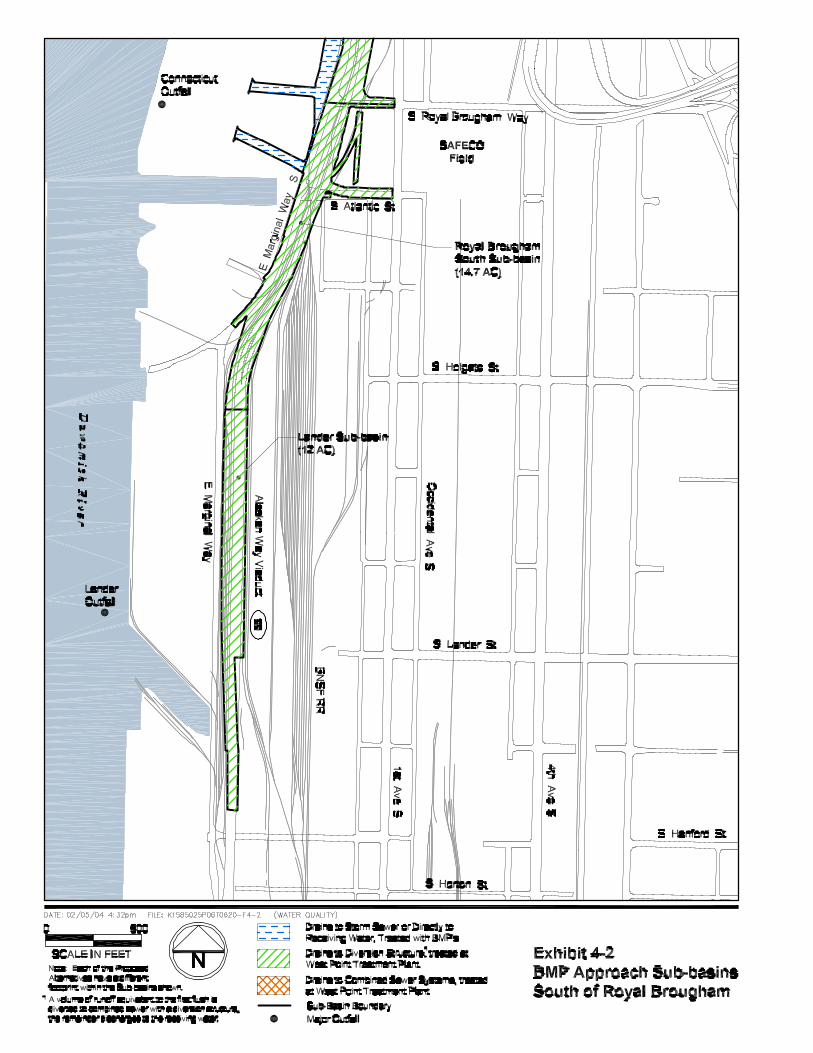

This Page Intentionally Left Blank
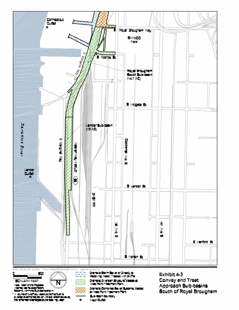

This Page Intentionally Left Blank

SR 99: Alaskan Way Viaduct & Seawall Replacement Project March 2004 Water Resources Discipline Report 47 Draft EIS
The BMP Approach
The BMP Approach is based on current WSDOT and City of Seattle stormwater management manuals (WSDOT 1995; Seattle 2001b). Under the BMP Approach, runoff from the project area in all the sub-basins will be treated and/or detained with stormwater BMPs. Stormwater treatment BMPs will be used in sub-basins where stormwater is collected in stormwater-only pipes and conveyed directly to Elliott Bay. Detention BMPs will be used to detain stormwater runoff prior to discharge to the combined sewer system. In addition, existing drainage paths and receiving waters will not change (Exhibits 4-4). King County is planning to construct the Royal Brougham TP by the year 2026. Therefore, it was assumed to be in place for the 2030 evaluation year of the project. Under existing conditions and the BMP Approach, it was assumed that the Royal Brougham TP will treat CSOs from the King Sub-basin as currently planned by King County. The Convey and Treat Approach
In the Central Business District, the Convey and Treat Approach will collect stormwater runoff and convey it to the combined sewer system, with treatment being provided at the West Point TP during normal operating conditions and some treatment being provided at the Denny Way CSO Treatment Facility during wet weather events (Exhibit 4-5).
CSOs south of Columbia Street will be treated at the proposed Royal Brougham TP. King County is planning to construct the Royal Brougham TP by the year 2026. Therefore, it was assumed to be in place for the 2030 evaluation year of the project. However, under the Convey and Treat Approach, this facility will be constructed earlier than planned and enlarged by 11 percent to treat additional flows from the project area that are not currently part of the combined sewer system, additional sanitary flows from cruise ships, and Terminal 46 expansion. If the capacity of the West Point TP, EBI, and Royal Brougham TP were ever exceeded, overflows would discharge to Elliott Bay as a reported CSO event.
North of Columbia Street, the combined sewer system will operate as under existing conditions. However, a greater volume of runoff will be conveyed to the combined system during all storms.

This Page Intentionally Left Blank


This Page Intentionally Left Blank