alaskan way viaduct replacement project -...
TRANSCRIPT
ALASKAN WAY VIADUCT REPLACEMENT PROJECTFinal Environmental Impact Statement
APPENDIX B Alternatives Description and Construction Methods
J U L Y 2 0 1 1
Submitted by:P A R S O N S B R I N C K E R H O F F
Prepared by:P A R A M E T R I X


SR 99: Alaskan Way Viaduct Replacement Project July 2011 Alternatives Description and Construction Methods Discipline Report Final EIS
Alaskan Way Viaduct Replacement Project Final EIS
Alternatives Description and Construction Methods Discipline Report
The Alaskan Way Viaduct Replacement Project is a joint effort between the Federal Highway Administration (FHWA), the Washington State Department of Transportation (WSDOT), and the City of Seattle. To conduct this project, WSDOT contracted with: Parsons Brinckerhoff 999 Third Avenue, Suite 3200 Seattle, WA 98104 In association with: Coughlin Porter Lundeen, Inc. EnviroIssues, Inc. GHD, Inc. HDR Engineering, Inc. Jacobs Engineering Group Inc. Magnusson Klemencic Associates, Inc. Mimi Sheridan, AICP Parametrix, Inc. Power Engineers, Inc. Shannon & Wilson, Inc. William P. Ott Construction Consultants

This Page Intentionally Left Blank

SR 99: Alaskan Way Viaduct Replacement Project July 2011 Alternatives Description and Construction Methods Discipline Report i Final EIS
TABLE OF CONTENTS Chapter 1 Introduction and Summary ................................................................................................................. 1
1.1 Introduction ................................................................................................................................................ 1 1.2 Project Background ................................................................................................................................... 1 1.3 Summary ................................................................................................................................................... 2
1.3.1 Construction Plans, Durations, and Sequencing ............................................................................. 3 1.4 Build Alternatives Overview ....................................................................................................................... 3
1.4.1 Elements Common to All Build Alternatives .................................................................................... 4 1.4.2 Bored Tunnel Overview ................................................................................................................... 5 1.4.3 Cut-and-Cover Tunnel Alternative Overview ................................................................................... 8 1.4.4 Elevated Structure Alternative Overview ....................................................................................... 10
1.5 List of Final EIS Appendices .................................................................................................................... 12 Chapter 2 Description of Alternatives ............................................................................................................... 13
2.1 Viaduct Closed (No Build Alternative) ...................................................................................................... 13 2.1.1 Viaduct Closed (No Build Alternative) 2030 Scenario 1: Sudden Unplanned Loss of SR 99 ........ 13 2.1.2 Viaduct Closed (No Build Alternative) 2030 Scenario 2: Catastrophic Failure and Collapse
of SR 99 ....................................................................................................................................... 13 2.1.3 2015 Existing Viaduct .................................................................................................................... 14
2.2 Elements Common to All Build Alternatives ............................................................................................ 14 2.2.1 Utility Relocations .......................................................................................................................... 14 2.2.2 Viaduct Removal ........................................................................................................................... 15
2.3 Bored Tunnel Alternative ......................................................................................................................... 16 2.3.1 South Portal Area .......................................................................................................................... 16 2.3.2 Bored Tunnel Alignment – Central ................................................................................................ 21 2.3.3 North Portal Area ........................................................................................................................... 23 2.3.4 Battery Street Tunnel Decommissioning ....................................................................................... 24 2.3.5 Program Elements ......................................................................................................................... 27
2.4 Cut-and-Cover Tunnel Alternative ........................................................................................................... 29 2.4.1 South – S. Royal Brougham Way to S. King Street ....................................................................... 29 2.4.2 Central – S. King Street to South Portal of Battery Street Tunnel ................................................. 32 2.4.3 Battery Street Tunnel – Portal to Portal ......................................................................................... 35 2.4.4 North – Battery Street Tunnel to Aloha Street ............................................................................... 36
2.5 Elevated Structure Alternative ................................................................................................................. 38 2.5.1 South – S. Royal Brougham Way to S. King Street ....................................................................... 38 2.5.2 Central – S. King Street to South Portal of Battery Street Tunnel ................................................. 40 2.5.3 Battery Street Tunnel – Portal to Portal ......................................................................................... 43 2.5.4 North – Battery Street Tunnel to Aloha Street ............................................................................... 43 2.5.5 Pine Street to Broad Street ............................................................................................................ 44
Chapter 3 Construction Elements and Methods .............................................................................................. 45 3.1 Construction Elements Common to All Build Alternatives ....................................................................... 45
3.1.1 Construction Staging Areas ........................................................................................................... 45 3.1.2 Construction Work Shifts ............................................................................................................... 49 3.1.3 Construction Haul Routes .............................................................................................................. 49 3.1.4 Construction Equipment ................................................................................................................ 50 3.1.5 Utility Relocations .......................................................................................................................... 51

SR 99: Alaskan Way Viaduct Replacement Project July 2011 Alternatives Description and Construction Methods Discipline Report ii Final EIS
3.1.6 Seattle Ferry Terminal Access During Construction ...................................................................... 52 3.2 Bored Tunnel Alternative – Construction Methods for Major Elements ................................................... 53
3.2.1 Construction Risks and Ground Improvement Methods ................................................................ 53 3.2.2 South Portal Area Construction ..................................................................................................... 59 3.2.3 Bored Tunnel Construction ............................................................................................................ 60 3.2.4 North Portal Area Construction ...................................................................................................... 67 3.2.5 Viaduct Demolition ........................................................................................................................ 68 3.2.6 Battery Street Tunnel Decommissioning ....................................................................................... 69 3.2.7 Surface Street Improvements and Restoration of Utilities ............................................................. 69
3.3 Cut-and-Cover Tunnel Alternative Construction Methods ....................................................................... 70 3.3.1 South – S. Royal Brougham Way to S. King Street ....................................................................... 70 3.3.2 Central – S. King Street to South Portal of Battery Street Tunnel ................................................. 71 3.3.3 North – Battery Street Tunnel to Aloha Street ............................................................................... 72
3.4 Elevated Structure Alternative Construction Methods ............................................................................. 73 3.4.1 South – S. Royal Brougham Way to S. King Street ....................................................................... 74 3.4.2 Central – S. King Street to South Portal of Battery Street Tunnel ................................................. 75 3.4.3 North – Battery Street Tunnel to Aloha Street ............................................................................... 76
Chapter 4 Construction Activities, Durations, and Roadway Restrictions ................................................... 79 4.1 Construction Assumptions for the Bored Tunnel Alternative ................................................................... 79 4.2 Construction Sequencing – Stages and Durations .................................................................................. 80 4.3 Bored Tunnel Alternative Construction Stages and Durations................................................................. 80
4.3.1 Bored Tunnel Traffic Stage 1 ......................................................................................................... 81 4.3.2 Bored Tunnel Traffic Stage 2 ......................................................................................................... 82 4.3.3 Bored Tunnel Traffic Stage 3 ......................................................................................................... 82 4.3.4 Bored Tunnel Traffic Stage 4 ......................................................................................................... 84 4.3.5 Bored Tunnel Traffic Stage 5 ......................................................................................................... 85 4.3.6 Bored Tunnel Traffic Stage 6 ......................................................................................................... 86 4.3.7 Bored Tunnel Traffic Stage 7 ......................................................................................................... 89 4.3.8 Bored Tunnel Traffic Stage 8 ......................................................................................................... 89
4.4 Cut-and-Cover Tunnel Alternative Construction Stages and Durations ................................................... 90 4.4.1 Cut-and-Cover Tunnel Traffic Stage 1 ........................................................................................... 91 4.4.2 Cut-and-Cover Tunnel Traffic Stage 2 ........................................................................................... 91 4.4.3 Cut-and-Cover Tunnel Traffic Stage 3 ........................................................................................... 93 4.4.4 Cut-and-Cover Tunnel Traffic Stage 4 ........................................................................................... 94 4.4.5 Cut-and-Cover Tunnel Traffic Stage 5 ........................................................................................... 95 4.4.6 Cut-and-Cover Tunnel Traffic Stage 6 ........................................................................................... 96
4.5 Elevated Structure Alternative Construction Stages and Durations ......................................................... 96 4.5.1 Major Detours ................................................................................................................................ 97 4.5.2 Elevated Structure Traffic Stage 1 ................................................................................................. 98 4.5.3 Elevated Structure Traffic Stage 2 ................................................................................................. 98 4.5.4 Elevated Structure Traffic Stage 3 ............................................................................................... 100 4.5.5 Elevated Structure Traffic Stage 4 ............................................................................................... 101 4.5.6 Elevated Structure Traffic Stage 5 ............................................................................................... 101 4.5.7 Elevated Structure Traffic Stage 6 ............................................................................................... 102 4.5.8 Elevated Structure Traffic Stage 7 ............................................................................................... 102 4.5.9 Elevated Structure Traffic Stage 8 ............................................................................................... 103
Chapter 5 References ....................................................................................................................................... 105

SR 99: Alaskan Way Viaduct Replacement Project July 2011 Alternatives Description and Construction Methods Discipline Report iii Final EIS
LIST OF EXHIBITS Exhibit 1-1. Other Projects Included in the Alaskan Way Viaduct and Seawall Replacement Program .................. 4Exhibit 1-2. Project Limits ....................................................................................................................................... 7Exhibit 2-1. New Dearborn Intersection ................................................................................................................ 18Exhibit 2-2. Bored Tunnel Alternative Cross-Section, Looking North .................................................................... 22Exhibit 2-3. Sixth Avenue Curved Alignment ........................................................................................................ 25Exhibit 2-4. Alignment of the Bored Tunnel Alternative ......................................................................................... 26Exhibit 2-5. Alignment of the Cut-and-Cover Tunnel Alternative ........................................................................... 30Exhibit 2-6. Cut-and-Cover Tunnel Alternative Cross-Section .............................................................................. 33Exhibit 2-7. Alignment of the Elevated Structure Alternative ................................................................................. 39Exhibit 2-8. Elevated Structure Alternative Cross-Section .................................................................................... 41Exhibit 3-1. Construction Staging Areas ............................................................................................................... 46Exhibit 3-2. Potential Locations for Compensation Grouting in the South Portal Area for Bored Tunnel Alternative
...................................................................................................................................................................... 54Exhibit 3-3. Compensation Grouting ..................................................................................................................... 56Exhibit 3-4. Jet Grouting and Deep Soil Mixing for Cut-and-Cover Tunnel and Elevated Structure Alternatives .. 58Exhibit 3-5. Typical Earth Pressure Balance Tunnel Boring Machine ................................................................... 64Exhibit 4-1. Traffic Stage 1 – Bored Tunnel Alternative Construction Activities and Approximate Durations ........ 81Exhibit 4-2. Traffic Stage 2 – Bored Tunnel Alternative Construction Activities and Approximate Durations ........ 82Exhibit 4-3. WOSCA Detour .................................................................................................................................. 83Exhibit 4-4. Traffic Stage 3 – Bored Tunnel Alternative Construction Activities and Approximate Durations ........ 84Exhibit 4-5. Traffic Stage 4 – Bored Tunnel Alternative Construction Activities and Approximate Durations ........ 85Exhibit 4-6. Traffic Stage 5 – Bored Tunnel Alternative Construction Activities and Approximate Durations ........ 86Exhibit 4-7. Traffic Stage 6 – Bored Tunnel Alternative Construction Activities and Approximate Durations ........ 87Exhibit 4-8. Revised WOSCA Detour .................................................................................................................... 88Exhibit 4-9. Traffic Stage 7 – Bored Tunnel Alternative Construction Activities and Approximate Durations ........ 89Exhibit 4-10. Traffic Stage 8 – Bored Tunnel Alternative Construction Activities and Approximate Durations ...... 90Exhibit 4-11. Traffic Stage 1 – Cut-and-Cover Tunnel Alternative Construction Activities and Approximate
Durations .......................................................................................................................................... 92Exhibit 4-12. Traffic Stage 2 – Cut-and-Cover Tunnel Alternative Construction Activities and Approximate
Durations .......................................................................................................................................... 92Exhibit 4-13. Traffic Stage 3 – Cut-and-Cover Tunnel Alternative Construction Activities and Approximate
Durations .......................................................................................................................................... 93

SR 99: Alaskan Way Viaduct Replacement Project July 2011 Alternatives Description and Construction Methods Discipline Report iv Final EIS
Exhibit 4-14. Traffic Stage 4 – Cut-and-Cover Tunnel Alternative Construction Activities and Approximate Durations .......................................................................................................................................... 94
Exhibit 4-15. Traffic Stage 5 – Cut-and-Cover Tunnel Alternative Construction Activities and Approximate Durations .......................................................................................................................................... 95
Exhibit 4-16. Traffic Stage 6 – Cut-and-Cover Tunnel Alternative Construction Activities and Approximate Durations .......................................................................................................................................... 96
Exhibit 4-17. Traffic Stage 1 – Elevated Structure Alternative Construction Activities and Approximate Durations ...................................................................................................................................................................... 98
Exhibit 4-18. Traffic Stage 2 – Elevated Structure Alternative Construction Activities and Approximate Durations ...................................................................................................................................................................... 99
Exhibit 4-19. Traffic Stage 3 – Elevated Structure Alternative Construction Activities and Approximate Durations .....................................................................................................................................................................100
Exhibit 4-20. Traffic Stage 4 – Elevated Structure Alternative Construction Activities and Approximate Durations .....................................................................................................................................................................101
Exhibit 4-21. Traffic Stage 5 – Elevated Structure Alternative Construction Activities and Approximate Durations .....................................................................................................................................................................101
Exhibit 4-22. Traffic Stage 6 – Elevated Structure Alternative Construction Activities and Approximate Durations .....................................................................................................................................................................102
Exhibit 4-23. Traffic Stage 7 – Elevated Structure Alternative Construction Activities and Approximate Durations .....................................................................................................................................................................102
Exhibit 4-24. Traffic Stage 8 – Elevated Structure Alternative Construction Activities and Approximate Durations .....................................................................................................................................................................103
SR 99: Alaskan Way Viaduct Replacement Project July 2011 Alternatives Description and Construction Methods Discipline Report v Final EIS
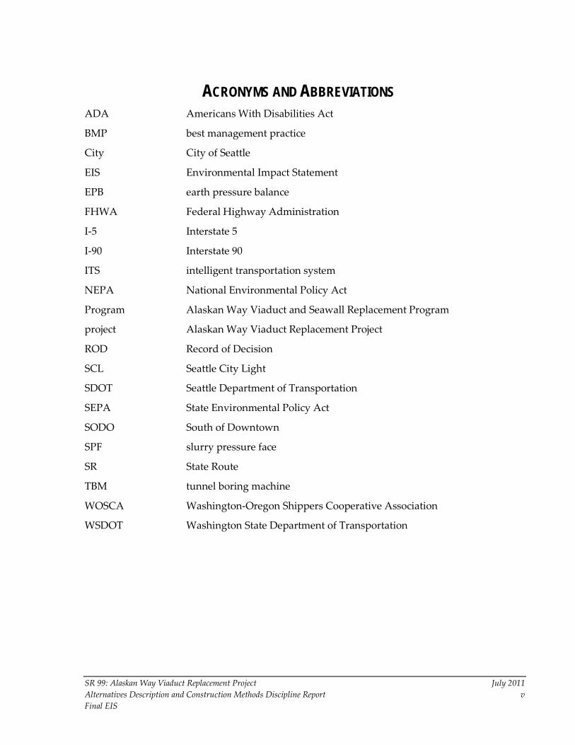
ACRONYMS AND ABBREVIATIONS ADA Americans With Disabilities Act
BMP best management practice
City City of Seattle
EIS Environmental Impact Statement
EPB earth pressure balance
FHWA Federal Highway Administration
I-5 Interstate 5
I-90 Interstate 90
ITS intelligent transportation system
NEPA National Environmental Policy Act
Program Alaskan Way Viaduct and Seawall Replacement Program
project Alaskan Way Viaduct Replacement Project
ROD Record of Decision
SCL Seattle City Light
SDOT Seattle Department of Transportation
SEPA State Environmental Policy Act
SODO South of Downtown
SPF slurry pressure face
SR State Route
TBM tunnel boring machine
WOSCA Washington-Oregon Shippers Cooperative Association
WSDOT Washington State Department of Transportation

This Page Intentionally Left Blank

SR 99: Alaskan Way Viaduct Replacement Project July 2011 Alternatives Description and Construction Methods Discipline Report 1 Final EIS
Chapter 1 INTRODUCTION AND SUMMARY 1.1 Introduction This discipline report describes the three build alternatives under consideration for replacing the Alaskan Way Viaduct: the Bored Tunnel Alternative (preferred), the Cut-and-Cover Tunnel Alternative, and the Elevated Structure Alternative. This report and the Alaskan Way Viaduct Replacement Project Final Environmental Impact Statement (EIS) that it supports are intended to provide new information and updated analyses to those presented in the October 2010 Alaskan Way Viaduct Replacement Project Supplemental Draft EIS (WSDOT et al. 2010) and the July 2006 Alaskan Way Viaduct and Seawall Replacement Project Supplemental Draft EIS (WSDOT et al. 2006). The designs for both the Cut-and-Cover Tunnel Alternative and the Elevated Structure Alternative have been updated since the 2006 Supplemental Draft EIS to reflect that the section of the viaduct between S. Holgate Street and S. King Street is being replaced by a separate project, and the roadway alignment at S. Washington Street is no longer in Elliott Bay.
Appendices C through R of the Final EIS present the detailed technical analyses of existing conditions and the predicted effects of the three build alternatives. The results of these analyses are found in the main volume of the Final EIS. For all of these project elements, the analyses of effects and benefits have been quantified (or described qualitatively, where applicable) with supporting studies. These analyses focus on assessing the potential effects associated with construction and operation of each of the three build alternatives and consider appropriate mitigation measures that could be used. In addition, all three build alternatives are evaluated under both tolled and non-tolled conditions.
The Viaduct Closed (No Build Alternative) is also analyzed.
1.2 Project Background The Federal Highway Administration (FHWA) is the lead federal agency for the Alaskan Way Viaduct Replacement Project (project), primarily responsible for compliance with the National Environmental Policy Act (NEPA) and other federal regulations, as well as distribution of federal funding. Per the NEPA process, FHWA was responsible for selecting the preferred alternative. FHWA based its decision on the information evaluated during the environmental review process, including the 2010 Supplemental Draft EIS. After this Final EIS is issued, FHWA can issue its NEPA decision, called the Record of Decision (ROD).
The 2004 Draft EIS (WSDOT et al. 2004) evaluated five Build Alternatives and a No Build Alternative. In December 2004, the project proponents identified the
SR 99: Alaskan Way Viaduct Replacement Project July 2011 Alternatives Description and Construction Methods Discipline Report 2 Final EIS
Cut-and-Cover Tunnel Alternative as the preferred alternative and carried the Rebuild Alternative forward for analysis as well. The 2006 Supplemental Draft EIS (WSDOT et al. 2006) analyzed two alternatives—a refined Cut-and-Cover Tunnel Alternative and a modified rebuild alternative called the Elevated Structure Alternative. After continued public and agency debate, Governor Gregoire called for an advisory vote to be held in Seattle. The March 2007 ballot included an elevated alternative and a surface-tunnel hybrid alternative. The citizens voted down both alternatives.
After this election, the lead agencies committed to a collaborative process to find a solution to replace the viaduct along Seattle’s central waterfront. In January 2009, Governor Gregoire, King County Executive Sims, and Seattle Mayor Nickels announced that the agencies had reached consensus and recommended replacing the aging viaduct with a bored tunnel.
The Bored Tunnel Alternative (preferred) was evaluated in the October 2010 Supplemental Draft EIS, and it is now being analyzed along with the Cut-and-Cover Tunnel and Elevated Structure Alternatives that are described in this discipline report and in the Final EIS. All three alternatives are evaluated both quantitatively and qualitatively.
1.3 Summary
1.3.1 Report Organization Chapter 2 describes the Viaduct Closed (No Build Alternative), the three build alternatives, and the elements of the larger Alaskan Way Viaduct and Seawall Replacement Program. The build alternatives are described from south to north in terms of their elements, surface street facilities, and associated features.
Chapter 3 describes the major construction elements and the construction methods most likely to be used to build the alternatives and complete the other elements of the project. These descriptions are intended to provide general information on how the project could be built, allowing leeway through the design and contracting process for other methods and approaches or variations of these methods to be used.
Chapter 4 describes the construction activities and estimated durations of construction for each of the build alternatives, as well as roadway restrictions or detours that would be needed. The overall construction plan has been divided into construction traffic stages; for each traffic stage, the estimated duration is provided, and the traffic routing plan is described. (The proposed alternate routes for transit and other transportation modes during construction are described in greater detail in Chapter 6 of Appendix C, Transportation Discipline Report.)

SR 99: Alaskan Way Viaduct Replacement Project July 2011 Alternatives Description and Construction Methods Discipline Report 3 Final EIS
Chapter 5 lists the references used to prepare this report.
1.3.2 Construction Plans, Durations, and Sequencing As part of the development of construction sequencing for the three build alternatives, the construction plan was divided into a series of traffic stages that represent significant changes in traffic flow and routes within the project area, such as detours or lane or roadway closures. Each traffic stage consists of a set of construction activities that must be substantially completed before the next traffic stage and the subsequent construction activities can begin.
The construction phasing and sequencing described in Chapter 4 are based on current planning and knowledge that the project team has acquired through numerous analyses.
For the Bored Tunnel Alternative, construction would require approximately 5.4 years (65 months). This construction period includes the removal of the viaduct once the bored tunnel is finished and ready for use.
For the Cut-and-Cover Tunnel Alternative, construction would require approximately 8.75 years (105 months). This construction period includes the removal of the viaduct once the cut-and-cover tunnel is finished and ready for use.
For the Elevated Structure Alternative, construction would require approximately 10 years (120 months). This construction period includes the concurrent removal of the existing viaduct (in sections) while the new structure is being built.
1.4 Build Alternatives Overview The Alaskan Way Viaduct Replacement Project is one of several independent projects developed to improve safety and mobility along State Route (SR) 99 and the Seattle waterfront from the South of Downtown (SODO) area to the Seattle Center. Collectively, these individual projects are often referred to as the Alaskan Way Viaduct and Seawall Replacement Program (Program). The Bored Tunnel Alternative has been selected as the preferred alternative for replacing the viaduct through downtown Seattle. See Exhibit 1-1 for a matrix of independent projects (Program elements) associated with the build alternatives. Section 2.3.5 provides detailed descriptions of these independent projects.
This Final EIS evaluates the cumulative effects of all the build alternatives; however, the potential direct and indirect environmental effects of the independent projects that complement the Bored Tunnel Alternative will be considered separately in independent environmental documents. See the Final EIS Chapter 7, Cumulative Effects Analysis, for the discussion of cumulative effects for each discipline.

SR 99: Alaskan Way Viaduct Replacement Project July 2011 Alternatives Description and Construction Methods Discipline Report 4 Final EIS
Exhibit 1-1. Other Projects Included in the Alaskan Way Viaduct and Seawall Replacement Program
Project Bored Tunnel Alternative
Cut-and-Cover Tunnel
Alternative
Elevated Structure
Alternative Independent Projects That Complement the Bored Tunnel Alternative
Elliott Bay Seawall Project X Included in alternative
Included in alternative
Alaskan Way Surface Street Improvements X Included in alternative
Included in alternative
Alaskan Way Promenade/Public Space X Included in alternative
Included in alternative
First Avenue Streetcar Evaluation X Included in alternative
Included in alternative
Elliott/Western Connector X Function provided1
Function provided1
Transit enhancements X Not proposed2 Not proposed2
Projects That Complement All Build Alternatives
S. Holgate Street to S. King Street Viaduct Replacement Project
X X X
Mercer West Project X X X Transportation Improvements to Minimize Traffic Effects During Construction
X X X
SR 99 Yesler Way Vicinity Foundation Stabilization
X X X
S. Massachusetts Street to Railroad Way S. Electrical Line Relocation Project
X X X
1. These specific improvements are not proposed with the Cut-and-Cover Tunnel and Elevated Structure Alternatives; however, these alternatives provide a functionally similar connection with ramps to and from SR 99 at Elliott and Western Avenues.
2. Similar improvements included with the Bored Tunnel Alternative could be proposed with this alternative.
1.4.1 Elements Common to All Build Alternatives
S. Holgate Street to S. King Street Viaduct Replacement Project The S. Holgate Street to S. King Street Viaduct Replacement Project is a separate project that started construction with early utility relocation in Spring 2010. However, it provides many of the components for the connections in the south section that were designed to accommodate any of the build alternatives for the central waterfront section being studied in this Final EIS.
Immediately south of the project area for the build alternatives discussed in this Final EIS, the viaduct is being replaced with a side-by-side bridge with three travel lanes in each direction as it passes over the BNSF Railway tail track and

SR 99: Alaskan Way Viaduct Replacement Project July 2011 Alternatives Description and Construction Methods Discipline Report 5 Final EIS
S. Atlantic Street as an aerial bypass structure. A northbound off-ramp and southbound on-ramp are provided on Alaskan Way S. between S. Royal Brougham Way and S. Dearborn Street.
This bypass bridge will allow traffic on S. Atlantic Street to travel over SR 99 and the BNSF Railway tail track. The S. Holgate Street to S. King Street Viaduct Replacement Project will remove the existing viaduct from S. Holgate Street to just south of S. Dearborn Street (in 2012) and will provide the temporary detour roadways and roadway structures connecting to the new SR 99 roadway, from the south side of S. Royal Brougham Way to the existing viaduct near S. King Street (in 2011). Use of the temporary on-and off-ramps constructed at S. Atlantic Street and S. Royal Brougham Way will continue during the construction of any of the build alternatives considered in the Final EIS.
Utility Relocations For the Bored Tunnel and the Cut-and-Cover Tunnel Alternatives, excavation would be required. Utilities would be either relocated or protected in place, depending on feasibility. The Elevated Structure Alternative would require less below-grade work and would result in fewer effects on utilities than the two tunnel alternatives.
Viaduct Removal With the Bored Tunnel alternative, the Alaskan Way Viaduct would be demolished after the viaduct replacement alternative is completed and operational. Demolition of the existing viaduct, from S. King Street to Battery Street, would take approximately 9 months.
With the Cut-and-Cover Tunnel Alternative, sections of the viaduct would be removed as replacement sections are completed.
With the Elevated Structure Alternative, sections of the existing viaduct would be removed as the new structure is built. By the time the new elevated structure is operational, all of the old viaduct structure would be removed.
Tolling Most of the discipline reports have a chapter (usually Chapter 7) that discusses the proposed build alternatives as tolled facilities, if the effects of tolling would be applicable to the element of the environment that is analyzed.
1.4.2 Bored Tunnel Overview The Bored Tunnel Alternative includes replacement of SR 99 with a bored tunnel and associated surface street improvements at the south and north portal areas. This alternative also includes relocating utilities located on or under the viaduct and relocating or protecting in place the utilities along the bored tunnel

SR 99: Alaskan Way Viaduct Replacement Project July 2011 Alternatives Description and Construction Methods Discipline Report 6 Final EIS
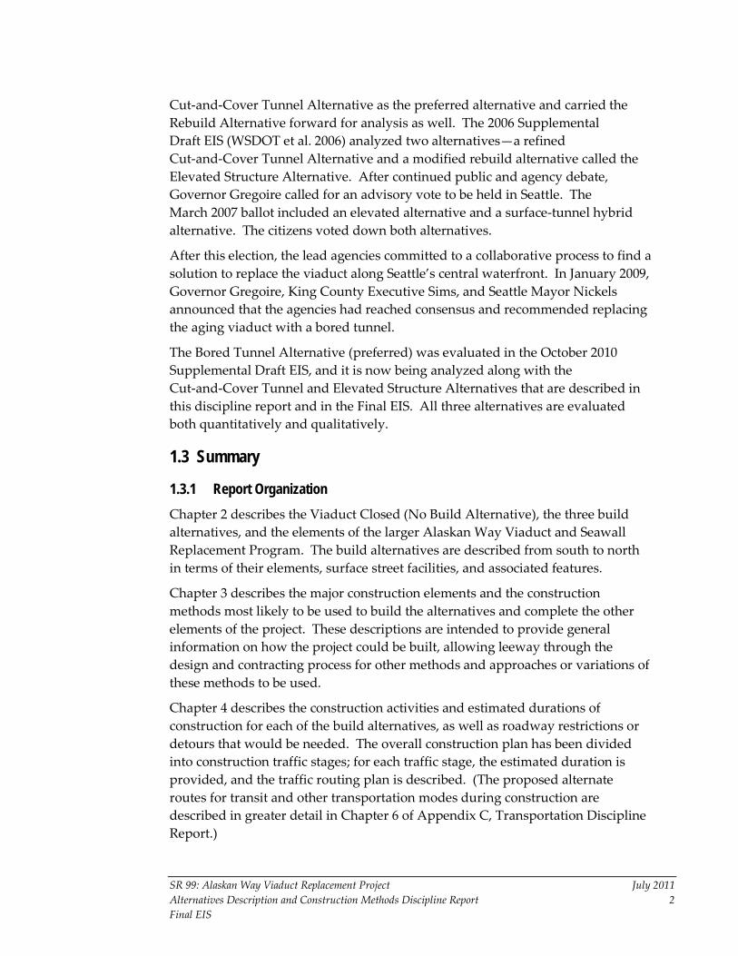
alignment. Other project elements are removal of the viaduct, decommissioning the Battery Street Tunnel, and improvements to the surface streets in the south and north portal areas. As shown on Exhibit 1-2, the project limits for the Bored Tunnel Alternative are approximately from S. Royal Brougham Way in the south to Roy Street in the north. The project limit in the south overlaps with project limit for the S. Holgate Street to S. King Street Viaduct Replacement Project. The east and west project limits in are more approximate, with Alaskan Way on the west and Interstate 5 (I-5) on the east. The construction limits may extend beyond these project limits.
The primary elements of the Bored Tunnel Alternative are the south portal area, the bored tunnel, and the north portal area.
The Bored Tunnel Alternative would replace SR 99 between S. Royal Brougham Way and Roy Street, with two lanes in each direction. The bored tunnel roadway would be approximately 1.75 miles long, with an inside diameter of 52 feet and an outside diameter of approximately 56 feet.
Beginning at S. Royal Brougham Way, SR 99 would be a side-by-side surface roadway that would descend to a cut-and-cover tunnel. At approximately S. King Street, SR 99 would enter the south portal of the bored tunnel in which the roadway would be stacked, with two southbound travel lanes on the top and two northbound travel lanes on the bottom.
The bored tunnel would continue under Alaskan Way S. to approximately S. Washington Street, where it would curve slightly away from the waterfront and then travel under First Avenue, beginning at approximately University Street. At Stewart Street, it would extend north under Belltown. At Denny Way, the bored tunnel would travel under Sixth Avenue N., where it would transition to a side-by-side surface roadway at about Harrison Street.
Access and exit ramps in the south would include a southbound on-ramp to and northbound off-ramp from SR 99 that would be built in retained cuts and feed directly into a reconfigured Alaskan Way S. with three lanes in each direction. Alaskan Way S. would have one new intersection, with the new east-west cross street at S. Dearborn Street.
The Bored Tunnel Alternative would also reconstruct a portion of east-west S. King Street and widen the East Frontage Road from S. Atlantic Street to S. Royal Brougham Way to accommodate truck turning movements. Railroad Way S. would be replaced by a new one-lane roadway on which northbound traffic could travel between S. Dearborn Street and Alaskan Way S.
S A T L A N T I C S T R E E T / S R 5 1 9
S D E A R B O R N
S W A S H I N G T O N S T R E E T
AL
AS
KA
N
WA
Y
S
C O L U M B I A S T R E E TS E N E C A S T R E E TP I K E S T R E E T
P I N E S T R E E TW
ES
TE
RN
AV
E
PI K
E P
L AC
E
AL A
SK
AN
WA
Y
EL
LI O
TT
AV
EN
UE
BA
Y S
T
BR
OA
D S
T
M E R C E R
D E N N Y W A Y
W A R D S T R E E T
A L O H A S T R E E T
J O H N S T R E E T
T H O M A S S T R E E T
S K I N G S T R E E T
Y E S L E R W A Y
S R O Y A L B R O U G H A M W A Y
S H O L G A T E
U N I O N S T R E E T
V A L L E Y S T R E E T
R O Y S T R E E T
H A R R I S O N S T R E E T
R E P U B L I C A N S T R E E T
90
Seatt le Center
SafecoField
QwestField
TERMINAL 46
E l l i o t t B a y
L a k eU n i o n
Battery Street Tunnel
Elliott & Western Ramps
North Portal
South Portal
Alaskan Way Viaduct
H A R B O R I S L A N D
Bored Tunnel
Seneca & Columbia Ramps
Existing SR 99
Battery Street Tunnel
Elevated Structure and Cut-and-CoverTunnel Alternatives
Bored Tunnel Alternative
Ramps are for Elevated StructureAlternative
Existing SR 99
Battery Street Tunnel
Elevated Structure and Cut-and-CoverTunnel Alternatives
Bored Tunnel Alternative
Ramps are for Elevated StructureAlternative
0 2,000
SCALE IN FEET
Exhibit 1-2Project Limits
3/15/11
SR 99: Alaskan Way Viaduct Replacement Project July 2011 Alternatives Description and Construction Methods Discipline Report 8 Final EIS
Immediately following the bored tunnel’s opening to traffic, the work to rebuild First Avenue S. and Alaskan Way would begin. A portion of the City Side Trail, used for bicycle and pedestrian travel along the east side of Alaskan Way, would be realigned as part of this project. The Port Side Trail would run along the west side of Alaskan Way.
Access from northbound SR 99 and access to southbound SR 99 would be provided via new ramps at Republican Street. The northbound off-ramp to Republican Street would be provided on the east side of SR 99 and routed to an intersection at Dexter Avenue N. Drivers would access the southbound on-ramp via a new connection with Sixth Avenue N. on the west side of SR 99.
Surface streets in the north portal area would be reconfigured and improved. The street grid between Denny Way and Harrison Street would be connected by restoring a section of Aurora Avenue just north of the existing Battery Street Tunnel portal. John, Thomas, and Harrison Streets would be connected as cross streets.
The Battery Street Tunnel would be decommissioned after the bored tunnel is operational. The Bored Tunnel Alternative would also remove the existing viaduct.
1.4.3 Cut-and-Cover Tunnel Alternative Overview The Cut-and-Cover Tunnel Alternative would replace the existing Alaskan Way Viaduct and the Elliott Bay Seawall. See Exhibit 1-2 which also shows the project limits for this alternative: S. Royal Brougham Way in the south, Aloha Street in the north, Elliott Bay in the west, and I-5 in the east.
The primary elements of the Cut-and-Cover Tunnel Alternative are the south portal area, the central tunnel section, the Battery Street Tunnel improvements, and the improvements to surface streets and Aurora Avenue from the north portal of the Battery Street Tunnel north to Aloha Street.
Work in the south portal area would include constructing the south tunnel portal and the tunnel maintenance building that would house the mechanical and ventilation systems.
In the central section, the cut-and-cover tunnel would be excavated with the new seawall being built as one wall of the tunnel. A temporary ferry access bridge between Pier 48 and Colman Dock would be built to maintain vehicle access throughout construction.
Work in the north portal area would include lowering the roadway profile of SR 99/Aurora Avenue between Denny Way and Republican Street. Mercer Street would be widened to accommodate two-way traffic. The street grid would be

SR 99: Alaskan Way Viaduct Replacement Project July 2011 Alternatives Description and Construction Methods Discipline Report 9 Final EIS
connected with Thomas and Harrison Streets constructed as bridges over Aurora Avenue.
The current project limits for the Cut-and-Cover Tunnel Alternative are somewhat different from those defined in the 2006 Supplemental Draft EIS due to the evolving design of this alternative and the configuration of the separate S. Holgate Street to S. King Street Viaduct Replacement Project immediately south of the cut-and-cover tunnel alignment.
The proposed waterfront tunnel would be just over a mile in length, extending from S. Jackson Street to Pine Street, with the west side of the tunnel wall replacing the existing Elliott Bay Seawall. Although SR 99 would be stacked throughout the central waterfront section, the lanes would be in a side-by-side configuration at both portals.
A six-lane stacked tunnel would replace the existing viaduct between S. King Street and Pine Street. At Pine Street, SR 99 would transition out of the tunnel near the Pike Street Hillclimb and would cross over the BNSF Railway tracks on a side-by-side aerial roadway covered by a walkway lid structure. Near Lenora Street, SR 99 would transition to a retained cut extending up to the south portal of the Battery Street Tunnel. SR 99 would travel under Elliott and Western Avenues. The southbound on-ramp from Elliott Avenue and the northbound on-ramp to Western Avenue would be rebuilt. The northbound on-ramp from Bell Street and the southbound off-ramp at Battery Street and Western Avenue would be closed and used for maintenance and emergency access only. The tunnel maintenance and operations buildings for the cut-and-cover tunnel would be located near each portal of the cut-and-cover tunnel. At the south portal near Railroad Way S., the building would likely be about 60 feet tall, with ventilation stacks extending up to 30 feet beyond the roof, which meets existing zoning and land use code requirements. In the north, the ventilation and tunnel maintenance building for the cut-and-cover tunnel would be built between Pike and Pine Streets on the east side of Alaskan Way.
The maintenance and ventilation buildings for the Battery Street Tunnel would be built at Second Avenue and Sixth Avenue. The buildings would be about 15 feet above the proposed roadway, with ventilation stacks extending up to 30 feet beyond the roof.
Maintenance and ventilation buildings would also be located at each end of Battery Street Tunnel, near where First Avenue intersects with Battery Street, near Denny Way. These buildings would likely vary in height from approximately 15 to 40 feet, with ventilation stacks 15 feet in height, and they are not expected to exceed the zoning height limitations. If potential conflicts with zoning regulations occur, they would be addressed by conditional use permit

SR 99: Alaskan Way Viaduct Replacement Project July 2011 Alternatives Description and Construction Methods Discipline Report 10 Final EIS
requirements. The tunnel operations and maintenance buildings would be designed to fit into the surrounding neighborhoods.
The Battery Street Tunnel would be lowered to match the roadway passing under Elliott and Western Avenues with widened portals to increase sight distance at the portals. The Battery Street Tunnel would also be retrofitted for improved seismic safety. The existing tunnel safety systems would be updated. Improvements would include a fire suppression system, ventilation, and new emergency egress structures near Second, Third, Fourth, and Sixth Avenues.
From the north portal of the Battery Street Tunnel, SR 99 would be lowered in a retained cut to about Mercer Street, with improvements. Mercer Street would be widened and rebuilt between Fifth and Dexter Avenues. Broad Street would be closed and filled between Fifth and Ninth Avenues, allowing the street grid to be connected. Mercer Street would continue to cross under SR 99 as it does today. However, it would be widened and converted from a one-way to a two-way street, with three lanes each way and a center turn lane.
Access to and from SR 99 would be provided at Denny Way and Roy Street. In the northbound direction, drivers could exit at Republican Street.
Alaskan Way would be rebuilt and would include multi-use pedestrian/bicycle paths on both the east and west sides. The Port Side Trail would be built along the west side of Alaskan Way, and the City Side Trail would travel along the east side of Alaskan Way.
1.4.4 Elevated Structure Alternative Overview The Elevated Structure Alternative would replace the existing viaduct mostly within the existing right-of-way (Exhibit 1-2). The current project limits are somewhat different from the project limits defined in the 2006 Supplemental Draft EIS due to refinements to this alternative and the configuration of the S. Holgate Street to S. King Street Viaduct Replacement Project. The current project limits are S. Royal Brougham Way in the south, Aloha Street in the north, Elliott Bay in the west, and I-5 in the east. The Elliott Bay Seawall would be rebuilt from S. Jackson Street to Broad Street.
At S. Royal Brougham Way, SR 99 would carry three lanes in each direction, with wider lanes and shoulders than the existing viaduct. The elevated structure would rise and cross over S. Dearborn Street and remain an aerial structure through the downtown core. The northbound on-ramp and southbound off-ramp connections could be made from S. Royal Brougham Way and S. Dearborn Street, respectively, to complete the full-access interchange in the stadium area. Other roadway improvements would include a new Alaskan Way aerial overpass of the BNSF Railway tail track, a new East Frontage Road between

SR 99: Alaskan Way Viaduct Replacement Project July 2011 Alternatives Description and Construction Methods Discipline Report 11 Final EIS
First Avenue S. and Alaskan Way, a S. Dearborn Street connection between First Avenue S. and Alaskan Way, and multi-use pedestrian/bicycle paths on both the east and west sides.
The existing ramps at Columbia and Seneca Streets would be rebuilt and connected to a fourth lane. This extra lane would improve safety for drivers accessing downtown Seattle on the midtown ramps.
The existing SR 99 roadway would be retrofitted, starting between Virginia and Lenora Streets and extending north to the south portal of the Battery Street Tunnel. SR 99 would travel over Elliott and Western Avenues to connect to the Battery Street Tunnel. This aerial structure would transition to four lanes as it enters the Battery Street Tunnel by dropping a northbound lane to Western Avenue.
The Battery Street Tunnel would be upgraded with new safety improvements, including a fire suppression system, seismic retrofitting, and access and egress structures. The vertical clearance would be increased to about 16.5 feet throughout the length of the tunnel. However, unlike the Battery Street Tunnel improvements associated with the Cut-and-Cover Tunnel Alternative, the roadway at the south portal would not be widened.
The Elliott and Western Avenue ramps would be rebuilt, and the existing southbound off-ramp at Battery Street and Western Avenue and the northbound on-ramp from Bell Street would be closed and used for maintenance and emergency access only.
The Alaskan Way surface street would be rebuilt. The southbound lanes would be built in a similar location as the existing roadway, and the northbound lanes would be constructed underneath the new elevated structure.
From the north portal of the Battery Street Tunnel, Aurora Avenue would be modified, from Denny Way to Aloha Street. Aurora Avenue would be lowered in a side-by-side retained cut roadway from the north portal of the Battery Street Tunnel to about Mercer Street, and it would be at-grade between Mercer and Aloha Streets. Ramps to and from Denny Way would provide access to and from SR 99 similar to today. The street grid would be connected over the new lowered Aurora Avenue at Thomas and Harrison Streets. Mercer Street would be widened and converted to a two-way street with three lanes in each direction and a center turn lane. It would continue to cross under Aurora Avenue as it does today.
SR 99: Alaskan Way Viaduct Replacement Project July 2011 Alternatives Description and Construction Methods Discipline Report 12 Final EIS
1.5 List of Final EIS Appendices The Final EIS includes the following appendices:
A. Public Involvement Discipline Report
B. Alternatives Description and Construction Methods Discipline Report
C. Transportation Discipline Report
D. Visual Quality Discipline Report
E. Visual Simulations
F. Noise Discipline Report
G. Land Use Discipline Report
H. Social Discipline Report
I. Historic, Cultural, and Archaeological Resources Discipline Report
J. Section 4(f) Supplemental Materials
K. Public Services and Utilities Discipline Report
L. Economics Discipline Report
M. Air Discipline Report
N. Wildlife, Fish, and Vegetation Discipline Report
O. Surface Water Discipline Report
P. Earth Discipline Report
Q. Hazardous Materials Discipline Report
R. Energy Discipline Report
S. 2004 Draft EIS and 2006 Supplemental Draft EIS Comments and Responses
T. 2010 Supplemental Draft EIS Comments and Responses
U. Final EIS Correspondence
V. FHWA and WSDOT response and draft document: Additional Review of the Impacts of Deep Bored Tunnel Tolling Diversion on City Streets; Identification of Mitigation
W. Screening Documents
X. Tolling Re-evaluation Memo

SR 99: Alaskan Way Viaduct Replacement Project July 2011 Alternatives Description and Construction Methods Discipline Report 13 Final EIS
Chapter 2 DESCRIPTION OF ALTERNATIVES 2.1 Viaduct Closed (No Build Alternative) Both federal and Washington State environmental regulations require agencies to evaluate a No Build Alternative to provide baseline information about existing conditions in the project area. For this project, the No Build Alternative is not a viable alternative, since the existing viaduct is vulnerable to earthquakes and structural failure due to ongoing deterioration. Multiple studies of the viaduct’s current structural conditions, including its foundations in liquefiable soils, have determined that retrofitting or rebuilding the existing viaduct between S. Royal Brougham Way and the Battery Street Tunnel is not a reasonable alternative (TY Lin 2005). At some point in the future, the roadway will need to be closed.
The 2030 Viaduct Closed (No Build Alternative) describes what would happen if the Bored Tunnel Alternative or one of the other build alternatives is not implemented. If the existing viaduct is not replaced, it will be closed, but it is unknown when that would happen. However, it is highly unlikely that the existing structure could still be in use in 2030. For these reasons, this Final EIS compares the effects of the proposed build alternatives to a 2015 Existing Viaduct.
The Viaduct Closed (No Build Alternative) describes the consequences of suddenly losing the function of SR 99 along the central waterfront based on the two scenarios described below. These consequences would be short term and would last until transportation and other agencies could develop and implement a new, permanent solution. The planning and development of the new solution would have its own environmental review.
2.1.1 Viaduct Closed (No Build Alternative) 2030 Scenario 1: Sudden Unplanned Loss of SR 99
Under this scenario, there would be a sudden, unplanned closure of SR 99 between S. King Street and the Battery Street Tunnel due to structural deficiencies, other types of deterioration, or a smaller earthquake event. Under this scenario, SR 99 would be closed for an unknown period of time until a viaduct replacement could be built. This would eliminate the use of the SR 99 mainline for the approximately 110,000 vehicle trips it now carries per day, and severe travel delays and congestion would be experienced.
2.1.2 Viaduct Closed (No Build Alternative) 2030 Scenario 2: Catastrophic Failure and Collapse of SR 99
This scenario considers the effects of a catastrophic failure and collapse of SR 99. Under this scenario, a seismic event of similar or greater magnitude than the

SR 99: Alaskan Way Viaduct Replacement Project July 2011 Alternatives Description and Construction Methods Discipline Report 14 Final EIS
February 2001 Nisqually earthquake could trigger failure of portions of the viaduct. This scenario would have the greatest effect on people and the surrounding environment. Failure of the viaduct could result in injury or death for people traveling on or near the structure at the time of the seismic event. This type of event could cause buildings to be damaged or collapse and would likely cause extensive damage to utilities. Severe travel delays would occur. The environmental effects and length of time it would take to repair the SR 99 corridor are unknown, but the effects would be substantial.
2.1.3 2015 Existing Viaduct The 2015 Existing Viaduct assumes that the existing viaduct will continue to be part of the transportation network between S. King Street and Denny Way in the year 2015. It also assumes construction of the new south end ramps as part of the separate S. Holgate Street to S. King Street Viaduct Replacement Project. For the environmental analysis in the Final EIS, traffic conditions are compared to the 2015 Existing Viaduct to describe how traffic operations are expected to change in the future. The analysis focuses on comparing the three proposed build alternatives with the 2015 Existing Viaduct; however, comparisons to post-earthquake conditions are also made to understand what could happen at some unknown time in the future.
2.2 Elements Common to All Build Alternatives
2.2.1 Utility Relocations In the south section, major utility relocations will have taken place as part of the separate S. Holgate Street to S. King Street Viaduct Replacement Project, before construction begins for any of the build alternatives.
Relocations of all underground utilities would involve similar construction activities and result in similar effects, including pavement removal and repaving, drainage, groundwater control, etc. Utility relocations would require the temporary closure of some streets and sidewalks, potentially affecting pedestrian and vehicle traffic (including transit) in the construction area, and detour routes would be established with the appropriate signage. For all utilities, there would be some disruption to utility services during the cutover from existing to temporary service feeds, and again, when the permanent utilities are installed. For greater detail regarding the construction effects on utilities, see Appendix K, Public Services and Utilities Discipline Report.
For the Bored Tunnel Alternative, construction of both the south and the north portals would involve excavation. This would affect all utilities within the footprint of both the retained cut and the cut-and-cover sections. Utility services connecting to adjacent properties would need to be temporarily relocated to

SR 99: Alaskan Way Viaduct Replacement Project July 2011 Alternatives Description and Construction Methods Discipline Report 15 Final EIS
maintain services during construction, and then relocated after construction, if necessary. Integrating these utility lines into the existing utility network may require tying into areas beyond the adjacent properties, and sometimes beyond the project limits.
For the Cut-and-Cover Tunnel Alternative, utilities would need to be replaced, relocated, or protected in place along the tunnel alignment, depending on the depth of the tunnel. Other relocations may occur during the initial stages of construction, and again in the end stages before surface street restoration. Utility relocation would require the temporary closure of some streets and sidewalk areas, potentially affecting both pedestrian and vehicle movements (including transit) in the construction area, although detour routes would be established and maintained. Before street restoration (toward the end of project construction), some of the utility services would need to be integrated into the existing network. This would likely require tying into areas beyond the adjacent properties, and beyond the project limits in some locations.
For the Elevated Structure Alternative, utilities that do not conflict with the construction of the elevated structure would remain in operation and be protected in place. The only utilities that would be located on the new elevated structure would be those utility services that are needed for the operational roadway.
2.2.2 Viaduct Removal For the two tunnel alternatives, the viaduct structure from approximately S. King Street to the Battery Street Tunnel would be demolished and removed once the bored tunnel is completed and the tunnel is operational. Viaduct demolition would require approximately 9 months. Demolition is currently proposed to occur concurrently in two locations along the viaduct alignment. Each of the two demolition crews would work in about two-block segments at a time. This means that up to four blocks of the viaduct could be under demolition at a given time.
With the Cut-and-Cover Tunnel Alternative, demolition would occur in sequence after certain sections of the cut-and-cover tunnel are constructed
The existing Marion Street pedestrian bridge from First Avenue to the Seattle Ferry Terminal would be demolished and replaced as part of all three build alternatives.
With the Bored Tunnel Alternative, the Lenora Street pedestrian bridge is expected to remain as it is today. Where the bridge terminates on the east side, modifications would be made to provide an at-grade pedestrian crossing on Elliott Avenue. The southbound on-ramp and the northbound off-ramp to Western Avenue would be removed along with the viaduct structure.
SR 99: Alaskan Way Viaduct Replacement Project July 2011 Alternatives Description and Construction Methods Discipline Report 16 Final EIS
The Cut-and-Cover Tunnel Alternative would remove and replace the Lenora Street pedestrian bridge. For the Elevated Structure Alternative, it has not been determined whether the Lenora Street pedestrian bridge would be removed and replaced or whether it would remain in place.
Some of the utilities buried beneath the existing viaduct may require relocation or replacement, because it would be difficult to ensure that they could be adequately protected in place.
Please see Section 3.4 for a description of viaduct demolition for the Elevated Structure Alternative.
2.3 Bored Tunnel Alternative The Bored Tunnel Alternative would replace SR 99 between S. Royal Brougham Way and Roy Street, with two lanes in each direction. Beginning at S. Royal Brougham Way, SR 99 would be a side-by-side surface roadway that would transition to a cut-and-cover tunnel section. At approximately S. King Street, SR 99 would enter the bored tunnel, with two southbound travel lanes on the upper level and two northbound travel lanes on the lower level.
The bored tunnel would continue under Alaskan Way S. to approximately S. Washington Street, where it would curve slightly away from the waterfront and then travel under First Avenue beginning at approximately University Street. At Stewart Street, it would extend north under Belltown.
At Denny Way, the bored tunnel would travel under Sixth Avenue N., where it would transition to a side-by-side surface roadway at about Harrison Street.
The Bored Tunnel Alternative would also include the removal of the existing viaduct after the completion of the bored tunnel. The Battery Street Tunnel would be closed after the new bored tunnel is completed. The current proposal is to use crushed rubble from the demolition of the existing viaduct to fill the Battery Street Tunnel approximately two-thirds full. The ends of the Battery Street Tunnel would be sealed with concrete, and barricades would be placed to prevent entry.
The Bored Tunnel Alternative consists of three primary elements: the south portal area, the bored tunnel, and the north portal area. Each of these elements is discussed in more detail below. Some of the specific design features are likely to change as the design continues to evolve.
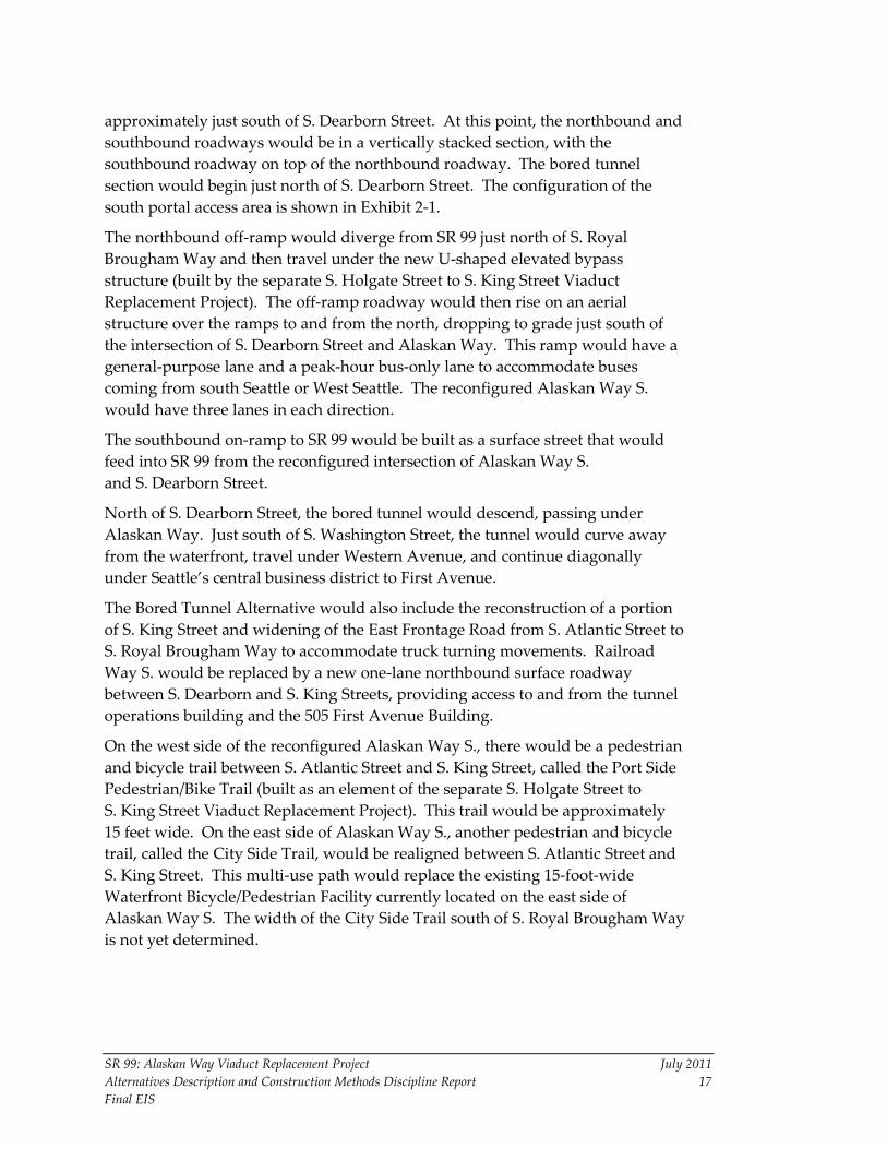
2.3.1 South Portal Area Between S. Royal Brougham Way and S. Dearborn Street, SR 99 would transition from a side-by-side surface roadway to a stacked cut-and-cover section. The northbound tunnel portal would be located approximately 250 feet north of S. Royal Brougham Way. The southbound tunnel portal would be located
SR 99: Alaskan Way Viaduct Replacement Project July 2011 Alternatives Description and Construction Methods Discipline Report 17 Final EIS
approximately just south of S. Dearborn Street. At this point, the northbound and southbound roadways would be in a vertically stacked section, with the southbound roadway on top of the northbound roadway. The bored tunnel section would begin just north of S. Dearborn Street. The configuration of the south portal access area is shown in Exhibit 2-1.
The northbound off-ramp would diverge from SR 99 just north of S. Royal Brougham Way and then travel under the new U-shaped elevated bypass structure (built by the separate S. Holgate Street to S. King Street Viaduct Replacement Project). The off-ramp roadway would then rise on an aerial structure over the ramps to and from the north, dropping to grade just south of the intersection of S. Dearborn Street and Alaskan Way. This ramp would have a general-purpose lane and a peak-hour bus-only lane to accommodate buses coming from south Seattle or West Seattle. The reconfigured Alaskan Way S. would have three lanes in each direction.
The southbound on-ramp to SR 99 would be built as a surface street that would feed into SR 99 from the reconfigured intersection of Alaskan Way S. and S. Dearborn Street.
North of S. Dearborn Street, the bored tunnel would descend, passing under Alaskan Way. Just south of S. Washington Street, the tunnel would curve away from the waterfront, travel under Western Avenue, and continue diagonally under Seattle’s central business district to First Avenue.
The Bored Tunnel Alternative would also include the reconstruction of a portion of S. King Street and widening of the East Frontage Road from S. Atlantic Street to S. Royal Brougham Way to accommodate truck turning movements. Railroad Way S. would be replaced by a new one-lane northbound surface roadway between S. Dearborn and S. King Streets, providing access to and from the tunnel operations building and the 505 First Avenue Building.
On the west side of the reconfigured Alaskan Way S., there would be a pedestrian and bicycle trail between S. Atlantic Street and S. King Street, called the Port Side Pedestrian/Bike Trail (built as an element of the separate S. Holgate Street to S. King Street Viaduct Replacement Project). This trail would be approximately 15 feet wide. On the east side of Alaskan Way S., another pedestrian and bicycle trail, called the City Side Trail, would be realigned between S. Atlantic Street and S. King Street. This multi-use path would replace the existing 15-foot-wide Waterfront Bicycle/Pedestrian Facility currently located on the east side of Alaskan Way S. The width of the City Side Trail south of S. Royal Brougham Way is not yet determined.

II
II
II
II
II
II
II
II
II
II
II
II
II
II
II
II
II
II
II
II
II
II
II
II
II
II
II
II
II
II
II
II
II
II
II
II
II
II
II
II
II
II
II
II
II
II
II
II
II
II
II
II
II
II
II
II
II
II
II
II
II
II
II
II
II
II
II
II
II
II
II
II
II
II
II
II
II
II
II
II
II
II
II
II
II
II
II
II
II
II
II
II
II
II
II
II
II
II
II
II
II
II
II
II
II
II
II
II
II
II
II
II
II
II
II
II
II
II
II
II
II
II
II
II
II
II
II
II
II
II
II
II
II
II
II
II
II
II
II
II
II
II
II
II
II
II
II
II
II
II
II
II
II
II
II
II
II
II
II
II
II
II
II
II
II
II
II
II
II
II
II
II
II
II
II
II
II
II
II
II
II
II
II
II
II
I
FIR
ST
AV
EN
UE
S
OC
CID
EN
TA
L A
VE
NU
E S
CO
LO
RA
DO
AV
EN
UE
S
RA
I LR
OA
D W
AY
S
AL
AS
KA
N W
AY
S
S R O Y A L B R O U G H A M W A Y
S A T L A N T I C S T R E E T / S R 5 1 9
S K I N G S T R E E T
S C H A R L E S
S D E A R B O R N
E F
RO
NT
AG
E R
OA
D
Qwest Field
Safeco Field
Street Improvements
Tunnel Egress
SR
99
Sou
thbo
und
Sou
thbo
und
On
Nor
thbo
und
On
Nor
thbo
und
Off
SR
99
Nor
thbo
und
Port SidePedestrian/Bike Trail
City Side Trail
TERMINAL 46
Tunnel Operations Building
New Dearborn Intersection
Surface Streets
Lowered Roadway
Retained Cut
Cut-and-Cover Tunnel
Bored Tunnel
Aerial
Bicycle/Pedestrian Facility
Sout
hbou
nd O
ff
3/15/11
0 400
SCALE IN FEET
Exhibit 2-1New Dearborn Intersection

SR 99: Alaskan Way Viaduct Replacement Project July 2011 Alternatives Description and Construction Methods Discipline Report 19 Final EIS
Amenities such as landscaping, pedestrian facility improvements, and transit priority features would be incorporated into the reconstructed surface streets in the area of Alaskan Way S. between S. Royal Brougham Way and S. King Street.
Alaskan Way S. would have one new intersection, with the new east-west cross street at S. Dearborn Street, as shown in Exhibit 2-1. The cross street would have sidewalks on both sides.
The Bored Tunnel Alternative would also include reconstruction of a portion of the east-west S. King Street and widening of the East Frontage Road from S. Atlantic Street to S. Royal Brougham Way to accommodate truck turning movements. Railroad Way S. would be replaced by a new one-lane roadway between the S. Dearborn Street and Alaskan Way S. intersection.
During construction, both south and north pedestrian connections along First Avenue S. between S. Royal Brougham Way and S. King Street would be maintained to the extent possible. There may be short periods of time when some of the connections may be detoured during key construction activities.
Seattle Ferry Terminal Access Currently, ferry traffic enters the Seattle Ferry Terminal from Alaskan Way, at Yesler Way. Alaskan Way carries two southbound lanes of traffic from Yesler Way and two northbound lanes from Spring Street. Exiting the ferry terminal at Yesler Way in the northbound direction on Alaskan Way is currently prohibited; northbound left turns from the ferry terminal are currently permitted at Marion Street only. The ferry terminal’s ingress and egress would likely be similar in the built condition, but will depend on the outcome of the City’s Central Waterfront design study.
Because there will be reduced lanes on Alaskan Way during construction, a second northbound lane between Yesler Way and Spring Street would be added to alleviate potential ferry queuing backups on Alaskan Way. During construction, ferry-bound traffic would be routed northbound on Alaskan Way using right-of-way under the existing viaduct north of the Seattle Ferry Terminal; it would then loop back southbound to access the ferry terminal from the north.
Tunnel Operations Building A tunnel operations building would be constructed in the block bounded by S. Dearborn Street, Alaskan Way S., and the new Railroad Way S. access road. The south portal tunnel operations building would have a tunnel maintenance operations area for tunnel monitoring staff, which could also be used as a backup tunnel emergency operations center in the event of an emergency. The building would be approximately 65 feet in height from surface street level, with an additional 30 feet in height for ventilation stacks extending above the 65-foot high
SR 99: Alaskan Way Viaduct Replacement Project July 2011 Alternatives Description and Construction Methods Discipline Report 20 Final EIS
building. Part of the building would be constructed underground to a depth of about 50 feet.
The tunnel operations building would provide ventilation to the tunnel by housing multiple large exhaust fans, which could also be used to supply air when required. This building would also serve as a distribution point for electrical and fire-suppression utilities serving the tunnel and the cut-and-cover roadway segment connecting to the tunnel.
A vertical fan arrangement would be used to conserve valuable urban real estate and minimize noise and exhaust at the street level. The design of the fan arrangement depends on calculations to determine the size adequate to accommodate fire emergency ventilation requirements of the tunnel. Height restrictions and the urban context will be considered as the building design proceeds.
A number of secondary elements, such as emergency generators and fuel tanks, would be incorporated into the tunnel operations building to support basic functions in the event of a power failure. Structures may require truck access with loading docks to facilitate the occasional movement of large equipment. A few small ancillary rooms that support other functions of tunnel operation may be included within the ventilation structure.
Bicycle and Pedestrian Facilities The Bored Tunnel Alternative would construct a 25-foot-wide multi-use path on the east side of SR 99. This City Side Trail would be realigned between S. Atlantic Street to S. King Street as part of this project, and would replace the existing 15-foot-wide Waterfront Bicycle/Pedestrian Facility currently located on the east side of Alaskan Way S. The Port Side Pedestrian/Bike on the west side of the Alaskan Way surface street, built as part of the separate S. Holgate to S. King Street Viaduct Replacement Project, would also be available.
Intelligent Transportation Systems The Bored Tunnel Alternative would include some intelligent transportation system (ITS) components, such as electronic sign boards, signage, and related fixtures. Improvements in the south and north portal areas could include the following ITS components:
• Variable message signs • Overheight vehicle warning signs with flashing beacons • Portal traffic signal • Tunnel closure gate • Tunnel closure sign • Detection loops

SR 99: Alaskan Way Viaduct Replacement Project July 2011 Alternatives Description and Construction Methods Discipline Report 21 Final EIS
• Surveillance cameras • Ramp meters • Tolling system equipment (if needed)
In the tunnel itself, the following ITS fixtures are likely to be installed:
• Variable message signs • Detection loops • Incident detection cameras • Surveillance cameras
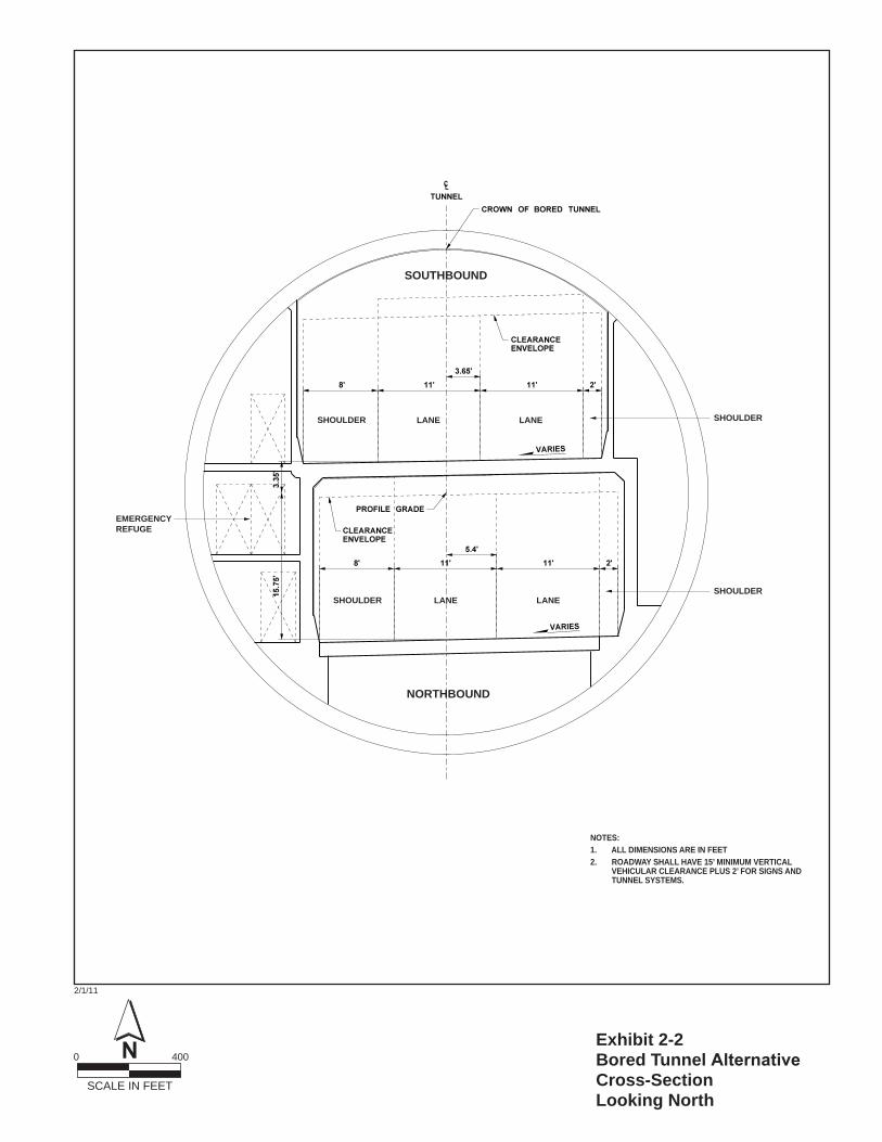
2.3.2 Bored Tunnel Alignment – Central At approximately S. King Street, the SR 99 stacked roadway would enter the bored tunnel, as shown in Exhibit 2-2. The bored tunnel would continue under Alaskan Way S. to approximately S. Washington Street, where it would curve slightly away from the waterfront and then travel under First Avenue beginning at approximately University Street. At Stewart Street, it would travel north under Belltown. At Denny Way, the bored tunnel would travel under Sixth Avenue N., where it would transition to a side-by-side surface roadway at about Harrison Street.
The bored tunnel would be approximately 1.75 miles long, with an inside diameter of 52 feet and an outside diameter of approximately 56 feet. The bored tunnel would have two lanes in each direction, which are expected to carry approximately 85,000 vehicles per day. The southbound lanes would be located on the top level of the tunnel, and the northbound lanes would be located on the bottom level. The travel lanes would be 11 feet wide, with a 2-foot-wide shoulder on one side and an 8-foot-wide shoulder on the other side. The wider shoulder would provide access for emergency vehicles and space for disabled vehicles to move out of the travel lane and wait for assistance.
The wider shoulder would also provide access to emergency tunnel exits, which would be provided at least every 650 feet. Signs would direct travelers to the nearest exit. In an emergency, travelers would walk along the shoulders to a doorway into a secure waiting area, called a refuge area, located between the tunnel levels. Emergency telephones would be available in the refuge areas.
A staircase inside the refuge area would provide access between the tunnel levels, allowing travelers to either wait in the refuge area for assistance or walk out of the tunnel.
The tunnel would be equipped with ventilation, a fire detection and suppression system, and drainage. Video cameras would provide real-time information to the operators at the Washington State Department of Transportation (WSDOT) 24-hour
2/1/11
0 400
SCALE IN FEET
Exhibit 2-2Bored Tunnel Alternative Cross-SectionLooking North
EMERGENCYREFUGE
NOTES:1. ALL DIMENSIONS ARE IN FEET2. ROADWAY SHALL HAVE 15’ MINIMUM VERTICAL VEHICULAR CLEARANCE PLUS 2’ FOR SIGNS AND TUNNEL SYSTEMS.
SOUTHBOUND
LANESHOULDER
NORTHBOUND
LANE
LANESHOULDER LANE
SHOULDER
SHOULDER
SR 99: Alaskan Way Viaduct Replacement Project July 2011 Alternatives Description and Construction Methods Discipline Report 23 Final EIS
tunnel control center and allow them to respond quickly to changing conditions and emergencies. The tunnel control center would be incorporated into one of the tunnel operations buildings at either the south or north tunnel portal.
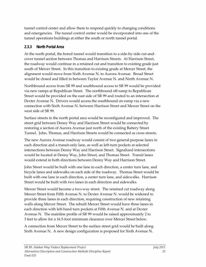
2.3.3 North Portal Area At the north portal, the bored tunnel would transition to a side-by-side cut-and-cover tunnel section between Thomas and Harrison Streets. At Harrison Street, the roadway would continue in a retained cut and transition to existing grade just south of Mercer Street. In this transition to existing grade at Mercer Street, the alignment would move from Sixth Avenue N. to Aurora Avenue. Broad Street would be closed and filled in between Taylor Avenue N. and Ninth Avenue N.
Northbound access from SR 99 and southbound access to SR 99 would be provided via new ramps at Republican Street. The northbound off-ramp to Republican Street would be provided on the east side of SR 99 and routed to an intersection at Dexter Avenue N. Drivers would access the southbound on-ramp via a new connection with Sixth Avenue N. between Harrison Street and Mercer Street on the west side of SR 99.
Surface streets in the north portal area would be reconfigured and improved. The street grid between Denny Way and Harrison Street would be connected by restoring a section of Aurora Avenue just north of the existing Battery Street Tunnel. John, Thomas, and Harrison Streets would be connected as cross streets.
The new Aurora Avenue roadway would consist of two general-purpose lanes in each direction and a transit-only lane, as well as left-turn pockets at selected intersections between Denny Way and Harrison Street. Signalized intersections would be located at Denny Way, John Street, and Thomas Street. Transit lanes would extend in both directions between Denny Way and Harrison Street.
John Street would be built with one lane in each direction, a center turn lane, and bicycle lanes and sidewalks on each side of the roadway. Thomas Street would be built with one lane in each direction, a center turn lane, and sidewalks. Harrison Street would be built with two lanes in each direction and sidewalks.
Mercer Street would become a two-way street. The retained cut roadway along Mercer Street from Fifth Avenue N. to Dexter Avenue N. would be widened to provide three lanes in each direction, requiring construction of new retaining walls along Mercer Street. The rebuilt Mercer Street would have three lanes in each direction with left-hand turn pockets at Fifth Avenue N. and at Dexter Avenue N. The mainline profile of SR 99 would be raised approximately 2 to 3 feet to allow for a 16.5-foot minimum clearance over Mercer Street below.
A connection from Mercer Street to the surface street grid would be built along Sixth Avenue N. A new design configuration is proposed for Sixth Avenue N.

SR 99: Alaskan Way Viaduct Replacement Project July 2011 Alternatives Description and Construction Methods Discipline Report 24 Final EIS
and the southbound on-ramp, as shown in Exhibit 2-3. The roadway would be built in a curved formation between Harrison and Mercer Streets. There would be a signalized intersection at the mid-point between Mercer and Harrison Streets for the southbound on-ramp that connects to southbound SR 99. The intersection at Mercer Street and Sixth Avenue N. would be signalized to direct all northbound Sixth Avenue traffic to turn left onto westbound Mercer Street or right onto eastbound Mercer Street.
As part of the north portal, a tunnel operations building would be constructed between Thomas and Harrison Streets on the east side of Sixth Avenue N. Part of the building would be built underground; the remaining portion is expected to be approximately 60 feet tall with ventilation stacks extending up to 35 feet above the roof. The tunnel operations building at the north portal would also house staff to monitor traffic and maintain tunnel operations, as well as to monitor any emergency events.
Roadway signage and pavement marking revisions would also be implemented approximately 1 mile north of the north portal area to provide direction to drivers using the new roadway and tunnel facilities (Refer to Exhibit 2-4, which shows the Bored Tunnel alignment.
2.3.4 Battery Street Tunnel Decommissioning The Battery Street Tunnel would be closed and decommissioned after the bored tunnel is opened to traffic. The cross streets above the tunnel and the utilities would be maintained. The current proposal is to use crushed rubble recycled from the existing viaduct to fill the tunnel approximately two-thirds full, and then pump in a low-strength concrete slurry to fill the remaining clearance space and solidify the rubble. Trucks would be the likely method of transporting the fill material to the Battery Street Tunnel site.
The concrete slurry mix used to top the crushed rubble fill would be poured from openings adjacent to the street above (Battery Street). The concrete mix would need to be poured from approximately seven locations along the Battery Street Tunnel.
Before the Battery Street Tunnel is filled, materials associated with the tunnel system components and other elements, such as asbestos transite conduit, lead-based paint, light fixtures, and light tubes containing heavy metals, would be removed. The sewer piping and inlets would be maintained for drainage purposes. Existing tunnel utility services will be removed and abandoned as required by the utility provider.

Bro
ad S
treet
Clo
sed
Broad Street Closed
Cut & CoverTunnel
TunnelEgress
Broad Street Closed
0 400
SCALE IN FEET
Exhibit 2-3Sixth Avenue Curved Alignment
3/15/11
LakeUnion
90
5
99
ElliottBay
Queen A
nne Ave N
Mercer St
SEATTLECENTER
Aloha St
Broad S
t
Denny Way
Alaskan WayBatt
ery S
t
Stewart
St
Pike St
Seneca St
Columbia StAlaskan Way Viaduct
Yesler Way
1st Ave
4th Ave
S King St
S Royal Brougham Way
S Atlantic St
W Mercer Pl
Elliott Ave W
0 1,800
SCALE IN FEET
Exhibit 2-4Alignment of the BoredTunnel Alternative
6/13/11
At-Grade
Cut-and-Cover
Bored Tunnel
Cut
Fill
Aerial Structure
Decommission BST
Broad Street Closed
SR 99: Alaskan Way Viaduct Replacement Project July 2011 Alternatives Description and Construction Methods Discipline Report 27 Final EIS
The ends of the tunnel would be sealed with concrete, and barricades would be placed to prevent entry. This is the general design approach currently being considered. Measures will be taken to ensure that access is maintained to allow adequate maintenance of utilities in and around the tunnel.
2.3.5 Program Elements The Alaskan Way Viaduct Replacement Project complements a number of other projects with independent utility that improve safety and mobility along SR 99 and the central waterfront. These projects, which are collectively referred to as the Alaskan Way Viaduct and Seawall Replacement Program, are described in the following subsections. It should be noted that these other Program-related projects apply primarily to the Bored Tunnel Alternative. These independent projects are not being evaluated with the Cut-and-Cover Tunnel Alternative or the Elevated Structure Alternative. (For greater detail regarding the Alaskan Way Viaduct and Seawall Replacement Program, see Chapter 1 of the Final EIS.)
Other Roadway Elements
The Alaskan Way surface street would be six lanes wide between S. King Street and Columbia Street (not including turn lanes), transitioning to four lanes between Marion and Pike Streets. In general, the new Alaskan Way surface street would be located on the east side of the right-of-way where the viaduct is located today. The new street would include new sidewalks, bicycle lanes, parking and loading zones, and signalized pedestrian crossings at cross streets. This large area of open right-of-way between the Elliott Bay Seawall and the east side of the existing viaduct structure would become available for a variety of uses beyond the Alaskan Way surface street. The City of Seattle (City) is currently involved in an intensive design study for the use of this area. The Alaskan Way surface street would be rebuilt with a promenade, sidewalk, and bicycle lane on the west and turn pockets in the center lane at alternating intersections. On the east side of Alaskan Way, a bicycle lane, parking lane, and sidewalk would be provided.
Alaskan Way Surface Street Improvements – S. King Street to Pike Street
The new roadway connecting Alaskan Way to Elliott and Western Avenues in the area between Pike and Battery Streets would be four lanes wide and would be at grade, except for the grade-separated crossing of the BNSF Railway mainline tracks. The new roadway would include bicycle and pedestrian facilities. The Lenora Street pedestrian bridge across the BNSF Railway tracks would become an at-grade pedestrian crossing of this new connector arterial. Where the pedestrian bridge terminates on the east side, modifications would be made to provide an at-grade pedestrian crossing on Elliott Avenue.
Elliott/Western Connector – Pike Street to Battery Street
SR 99: Alaskan Way Viaduct Replacement Project July 2011 Alternatives Description and Construction Methods Discipline Report 28 Final EIS
Mercer Street would be restriped and signalized between Fifth Avenue N. and Second Avenue W. to create a two-way street with turn pockets. These improvements would also include the restriping and resignalization necessary to convert Roy Street to two-way operations from Fifth Avenue N. to Queen Anne Avenue N.
Mercer West Project – Fifth Avenue N. to Elliott Avenue
Non-Roadway Elements
The Elliott Bay Seawall needs to be replaced to protect the shoreline along Elliott Bay, including Alaskan Way. It is at risk of failure due to seismic and storm events. The seawall currently extends from S. Washington Street in the south to Pine Street in the north, a distance of about 8,000 feet. The Elliott Bay Seawall Project limits are S. Jackson Street in the south and Broad Street in the north (also known as the central seawall). The southern one-third of the central seawall was built in 1916 and rebuilt in 1987. The northern two-thirds of the central seawall were constructed between 1934 and 1936.
Elliott Bay Seawall Project
A new expanded waterfront promenade and public space would be provided to the west of the new Alaskan Way surface street, between S. King Street and Pike Street. Between Marion and Pike Streets, this public space would be approximately 70 to 80 feet wide. This public space will be designed at a later date. Access to the piers would be provided by service driveways. Other potential open space sites include a triangular space north of Pike Street and east of Alaskan Way, and parcels created by the removal of the Alaskan Way Viaduct between Lenora and Battery Streets.
Alaskan Way Promenade/Public Space
The City is leading this project and its associated environmental process, which would take place under NEPA and/or State Environmental Policy Act (SEPA) review of central waterfront improvements as appropriate. This project will evaluate a new streetcar line along First Avenue between Pioneer Square and Seattle Center in the City’s transit plan. This alignment would pass through several of Seattle’s densest neighborhoods, including Pioneer Square, the downtown Central Business District, Belltown, and Uptown. It would serve many tourist and regional attractions, such as Pike Place Market, the Seattle waterfront piers, Seattle Art Museum, Seattle Aquarium, Olympic Sculpture Park, and Seattle Center.
First Avenue Streetcar Evaluation
The Cut-and-Cover Tunnel and Elevated Structure Alternatives propose to build a streetcar on Alaskan Way as part of the Alaskan Way surface street
SR 99: Alaskan Way Viaduct Replacement Project July 2011 Alternatives Description and Construction Methods Discipline Report 29 Final EIS
improvements. The Bored Tunnel Alternative does not include building a streetcar on the central waterfront. Instead, Governor Gregoire, former Seattle Mayor Nickels, and former County Executive Sims proposed constructing a streetcar on First Avenue as part of their recommendation from the Partnership Process.
A variety of transit enhancements would be provided to support planned transportation improvements associated with the Program and accommodate future demand. Development of the specific improvements is underway. These transit enhancements include (1) the Delridge RapidRide line, (2) additional service hours on the West Seattle and Ballard RapidRide lines, (3) peak-hour express routes added to the South Lake Union and Uptown neighborhoods, (4) local bus changes (such as realignments and a few additions) to several West Seattle and northwest Seattle routes, (5) implementation of transit signal priority on S. Main and/or S. Washington Streets between Alaskan Way and Third Avenue, and (6) simplification of the electric trolley system. RapidRide transit along the Aurora Avenue corridor would also be provided.
Transit Enhancements
2.4 Cut-and-Cover Tunnel Alternative The Cut-and-Cover Tunnel Alternative would replace the existing Alaskan Way Viaduct and Elliott Bay Seawall, as shown in Exhibit 2-5. The proposed waterfront tunnel would extend just over a mile in length (approximately 5,300 feet) from S. Jackson Street to Pine Street, with the west side of the tunnel wall replacing the existing seawall.
Under the Cut-and-Cover Tunnel Alternative, no midtown on- or off-ramps would be provided, but access would be enhanced in the south portal area, where access to and from downtown would be provided at First Avenue near S. Royal Brougham Way and S. Dearborn Street.
2.4.1 South – S. Royal Brougham Way to S. King Street The S. Holgate Street to S. King Street Viaduct Replacement Project (separate project) is building a side-by-side elevated SR 99 alignment immediately south of the project area for the Cut-and-Cover Tunnel Alternative. The segment between S. Holgate Street and S. King Street is being replaced with a three-lane (in each direction) configuration where it passes over S. Atlantic Street and the BNSF Railway tail track.
The Cut-and-Cover Tunnel Alternative would provide two southbound lanes that would emerge from the tunnel to be joined by a southbound on-ramp from the Alaskan Way surface street to merge with the SR 99 mainline traffic near

LakeUnion
At-Grade
Cut-and-Cover
Cut
Fill
Aerial Structure
Below Grade
Broad Street Closed
90
5
99
ElliottBay
Queen A
nne Ave N
Mercer St
SEATTLECENTER
Aloha St
Broad S
t
Denny Way
Alaskan WayBatt
ery S
t
Stewart
St
Pike St
Seneca St
Columbia StAlaskan Way Viaduct
Yesler Way
1st Ave
4th Ave
S King St
S Royal Brougham Way
S Atlantic St
W Mercer Pl
Elliott Ave W
0 1,800
SCALE IN FEET
Exhibit 2-5Alignment of theCut-and-Cover TunnelAlternative
6/13/11
SR 99: Alaskan Way Viaduct Replacement Project July 2011 Alternatives Description and Construction Methods Discipline Report 31 Final EIS
S. Royal Brougham Way. Two of the three northbound lanes would enter the cut-and-cover tunnel, and the third lane would become an off-ramp continuing north to the Alaskan Way surface street. The northbound off-ramp would consist of a general-purpose lane and a peak-hour transit-only lane to accommodate transit coming from south Seattle or West Seattle.
Within the cut-and-cover tunnel, a southbound off-ramp would diverge and exit onto the East Frontage Road and continue south to the at-grade intersections at S. Royal Brougham Way and S. Atlantic Street. A northbound on-ramp would enter the tunnel portal from the East Frontage Road and merge with SR 99 traffic within the cut-and-cover tunnel.
One new surface intersection would be built above the cut-and-cover tunnel at S. Dearborn Street. At this intersection, the seven-lane surface street to the north would provide the southbound lanes to access the southbound on-ramp to SR 99. This intersection would also provide access to the two-lane East Marginal Way S. on the west side of SR 99 and allow a continuation of three northbound lanes coming from the SR 99 off–ramp, as well as a connection to four lanes on S. Dearborn Street connecting to First Avenue.
Railroad Way S. would be replaced by a public open space area along First Avenue and an access driveway and parking lot serving the tunnel portal building.
The tunnel portal building would be constructed in the block bounded by S. Dearborn Street, Alaskan Way S., and a new Railroad Way S. access road. The tunnel portal building would house electrical and mechanical equipment, including large fans and exhaust stacks for tunnel ventilation and operations and maintenance equipment. Part of the building would be constructed underground. The remaining portion of the building is expected to be approximately 60 feet tall with ventilation stacks extending up to 30 feet above the roof.
During construction of the Cut-and-Cover Tunnel Alternative and the Elevated Structure Alternative, the Washington Street Boat Landing at the foot of Washington Street would need to be relocated. After construction, the pergola would be returned to the same location.
Bicycle and Pedestrian Facilities Like the Bored Tunnel Alternative, the Cut-and-Cover Tunnel Alternative would construct a 25-foot-wide multi-use path on the east side of SR 99. This City Side Trail would extend north from S. Atlantic Street to S. King Street and would replace the existing 15-foot-wide Waterfront Bicycle/Pedestrian Facility currently located on the east side of Alaskan Way S. The Port Side Pedestrian/Bike on the west side of the Alaskan Way surface street, built as part of the separate S. Holgate to S. King Street Viaduct Replacement Project, would also be available.

SR 99: Alaskan Way Viaduct Replacement Project July 2011 Alternatives Description and Construction Methods Discipline Report 32 Final EIS
Alaskan Way Surface Street The Cut-and-Cover Tunnel Alternative would remove the Alaskan Way Viaduct; therefore, the Alaskan Way surface street would be opened up to create a large section of right-of-way between the seawall and the east side of the existing viaduct structure. This area would be available for a variety of recreational and common area uses, and the City is currently involved in an intensive Central Waterfront design study for its use.
2.4.2 Central – S. King Street to South Portal of Battery Street Tunnel The cut-and-cover tunnel would transition from a side-by-side, six-lane configuration to a stacked tunnel configuration, as it continues north from just south of S. King Street. The depth of the stacked tunnel would range from 78 to 86 feet, and the width would range from 77 to 90 feet. Inside the tunnel, a minimum vertical clearance of 16.5 feet would be maintained in both directions.
Emergency egress to the surface would be located on the east side of the cut-and-cover tunnel. At the emergency egress points, which would be spaced approximately every 600 feet, there would be stairways to the surface.
The cut-and-cover tunnel would also be equipped with a fire suppression system, and ventilation structures would be located near the portals at S. King Street in the south and at Pine Street in the north.
The tunnel alignment would transition from a stacked double-level configuration to a side-by-side configuration between Spring Street and Union Street, and it would continue north in a side-by-side configuration to the Battery Street Tunnel. See Exhibit 2-6 for a generalized cross-section view.
The cut-and-cover tunnel would extend above grade between Union and Pike Streets. At Pike Street, the northbound tunnel lanes would be about 22 feet above the Alaskan Way surface street. In this portion of the project area, there would be a triangular maintenance and equipment building extending about 400 feet along the east side of the Alaskan Way surface street and; it would be about 250 feet wide at Pine Street. The building is proposed to feature vertical street walls fronting on Alaskan Way and Pine Street, which would allow public space on top of the building on a flat or stepped roof surface.
At Pike Street, the walkway lid would step down about 10 feet to the west over the southbound tunnel, which allows a two-tier stairway from the Pike Street Hillclimb on the east to the Alaskan Way surface street on the west. The top of the walkway lid would connect to the Pike Street Hillclimb at Western Avenue on a pedestrian bridge. On the east side of the tunnel wall would be an access roadway and parking areas extending to the existing parking garage. This area would be bounded by the east wall of the tunnel, which would be about 20 feet high at Pike Street and nearly 35 feet high at the edge of the existing parking garage.

Exhibit 2-6Cut-and-Cover Tunnel AlternativeCross Section
5/17/11

SR 99: Alaskan Way Viaduct Replacement Project July 2011 Alternatives Description and Construction Methods Discipline Report 34 Final EIS
From about Pine Street north, a new above-grade roadway would connect the new waterfront tunnel to the Battery Street Tunnel, as well as to the Western and Elliott Avenue ramps. At Pine Street, SR 99 would transition out of the tunnel and begin to break through existing grade about 120 feet south of the Pike Street Hillclimb. SR 99 would cross over the BNSF Railway tracks on a side-by-side aerial roadway.
The cut-and-cover tunnel’s portal operations building would be located just south of Pine Street, west of Pike Place Market. The structure would be completely above grade.
Temporary Ferry Access Bridge Both the Cut-and-Cover Tunnel Alternative and the Elevated Structure Alternative would include the construction of a temporary overwater ferry access bridge between Pier 48 and Colman Dock (between S. Washington Street and Yesler Way). See Chapter 6 of Appendix N, Wildlife, Fish, and Vegetation Discipline Report. This bridge would be needed during construction to maintain access and egress for ferry operations. Once the project is completed, this overwater bridge would be removed.
Ferry Access and Ferry Holding For both the Cut-and-Cover Tunnel Alternative and the Elevated Structure Alternative, the remote holding for vehicles waiting to board ferries would be relocated to a site east of SR 99, between First Avenue S. and Alaskan Way. Ferry traffic traveling to the Seattle Ferry Terminal (at Colman Dock) would travel north on First Avenue S. from the stadium area to access the remote holding site. Traffic leaving Colman Dock would travel south on First Avenue to access the southbound SR 99 on-ramp at S. Royal Brougham Way.
The specific access to ferry holding for this alternative has not yet been determined, but it would likely be on the east side of SR 99. Pedestrian access would be maintained throughout construction.
After waterfront construction is completed, the Marion Street pedestrian bridge from First Avenue to the Seattle Ferry Terminal would be rebuilt.
Elliott Bay Seawall The Cut-and-Cover Tunnel Alternative would replace the deteriorating Elliott Bay Seawall between S. Jackson and Broad Streets using soil strengthening methods, followed by the construction of a new L-wall support structure and new face panels. After construction of the new seawall, the existing structures would be removed to the mudline, where feasible.

SR 99: Alaskan Way Viaduct Replacement Project July 2011 Alternatives Description and Construction Methods Discipline Report 35 Final EIS
SR 99 Under Elliott and Western Avenues Between Lenora Street and the Battery Street Tunnel, SR 99 would travel in a new lowered roadway (retained cut) section with overpasses at Elliott and Western Avenues and at the Bell Street intersection. Building SR 99 under Elliott and Western Avenues would require a combination of retained cuts and bridges. Roadway grade changes can affect utilities, which may require utility relocations.
Under Western Avenue, the northbound lanes would change to a 7 percent uphill grade, connecting with the south portal of the Battery Street Tunnel. The northbound outside lane would split off from the through lanes between Virginia and Lenora Streets and ascend to Western Avenue as an exit ramp.
Similarly, the southbound lanes would exit the Battery Street Tunnel at a 7 percent downhill grade and would immediately pass below Western and Elliott Avenues, transitioning to a slight uphill grade. South of Elliott Avenue, the Elliott on-ramp would begin as an aerial structure and would join the southbound lanes (also on an aerial structure) past Lenora Street. These three lanes would continue on the aerial structure over the BNSF Railway tracks. An emergency fire access and maintenance lane would be provided behind the Waterfront Landings condominiums.
The Elliott Avenue on-ramp and Western Avenue off-ramp would be rebuilt. These ramps would provide access to and from the Ballard/Interbay corridor.
The existing southbound off-ramp and northbound on-ramp near Battery Street would be rebuilt. These ramps would be closed to general-purpose traffic and used for emergency access only.
A service (or frontage) road would connect the Alaskan Way surface street to businesses east of the cut-and-cover tunnel. The service road would be located under a pedestrian walkway lid at the Pike Street Hillclimb.
Under the Cut-and-Cover Tunnel Alternative, no midtown on- or off-ramps would be provided, but access would be enhanced in the south portal area, where access to and from downtown would be provided near S. Royal Brougham Way and S. Dearborn Street, as described in Section 2.4.
2.4.3 Battery Street Tunnel – Portal to Portal With the Cut-and-Cover Tunnel Alternative, the Battery Street Tunnel would be retrofitted for improved seismic safety. The existing tunnel safety systems and facilities would be updated with a fire suppression system, ventilation, and new emergency egress structures on both sides of the tunnel near Second, Third, Fourth, and Sixth Avenues. The south portal would be widened to accommodate the connection from the new SR 99 roadway.

SR 99: Alaskan Way Viaduct Replacement Project July 2011 Alternatives Description and Construction Methods Discipline Report 36 Final EIS
The proposed improvements include the following:
• Seismically retrofitting the facility
• Maintaining two 11-foot-wide lanes in each direction, with 2-foot offsets from the face of the concrete barriers adjacent to the tunnel walls
• Designating the northbound on-ramp from Bell Street and southbound off-ramp to Western Avenue for emergency and maintenance vehicle use only
• Lowering the south portal to match the roadway passing under Elliott and Western Avenues
• Widening the south curve to provide greater sight distance, and providing a minimum vertical vehicle clearance of 16.5 feet, with an additional 6-inch allowance for fire sprinklers and other ceiling-mounted systems throughout the length of the tunnel
• Retrofitting, improving, and constructing additional emergency egress/ingress facilities
• Upgrading the ventilation, fire suppression, and electrical/illumination systems
• Upgrading the ITS, including incident response and public advisories, which can also be remotely controlled from tunnel support and maintenance buildings
On the south end of the tunnel, near Western Avenue, a new public open space would be built on top of the tunnel maintenance and ventilation building.
2.4.4 North – Battery Street Tunnel to Aloha Street The improvements proposed for SR 99 between the north portal of the Battery Street Tunnel and Aloha Street include lowering the roadway profile into a side-by-side retained cut between the north portal and about Mercer Street. The northbound roadway would descend from the north portal of the Battery Street Tunnel to Thomas Street before rising to cross over Mercer Street to return to existing grade near Roy Street. Roadway grade changes can affect utilities, which may require utility relocations.
The northbound roadway improvements would include two lanes exiting the north portal of the Battery Street Tunnel, with one lane added from a left-hand lane on to SR 99 at Denny Way. From Denny Way north to Aloha Street, northbound SR 99 would consist of three lanes, matching up with the existing three-lane section north of Aloha Street.
The existing southbound three-lane configuration at Aloha Street would continue south to Thomas Street. The right lane would exit at Denny Way, and two lanes

SR 99: Alaskan Way Viaduct Replacement Project July 2011 Alternatives Description and Construction Methods Discipline Report 37 Final EIS
would continue into the Battery Street Tunnel. Connections on and off SR 99 would be provided at Roy Street.
The roadway configuration would provide 11-foot through lanes, 12-foot on- and off-connection lanes, 4-foot left shoulders, and 10-foot right shoulders. North of the retained cut, where existing development requires pedestrian access, the right shoulder would be replaced by a curb and sidewalk.
Alaskan Way Surface Street The Alaskan Way surface street presents a large area of open right-of-way between the Elliott Bay Seawall and the east side of the existing Alaskan Way Viaduct structure, which would become available for a variety of uses beyond the rebuilt Alaskan Way surface street. The City is currently involved in an intensive design study for the use of this area. The Alaskan Way surface street would be rebuilt with a promenade, sidewalk, and bicycle lane on the west and two sets of streetcar tracks with streetcar stops and turn pockets in the center lane at alternating intersections. On the east side of Alaskan Way, a bicycle lane, parking lane, and sidewalk would be provided.
Elliott Bay Seawall As discussed in Section 2.4.2, the existing Elliott Bay Seawall in this section would be reconstructed between about Pine Street and Broad Street.
Aurora Avenue Improvements The Aurora Avenue improvements would include the following features:
• From the north portal of the Battery Street Tunnel, SR 99 would be lowered from Denny Way to Mercer Street.
• Creating cul-de-sac street ends at John, Valley, and Aloha Streets to restrict access to and from SR 99 between Denny Way and Ward Street.
• Providing a northbound left-side Denny Way on-ramp and rebuilding the southbound Denny Way ramp in its existing configuration.
• Providing right-turn on and off movements for both the northbound and the southbound lanes at Roy Street with right-turn lanes and acceleration lanes.
• Removing the existing southbound off-ramp to Broad Street and the northbound off-ramp to Dexter Avenue.
• Providing a northbound right-turn off connection at Republican Street.
• Closing and backfilling Broad Street between Fifth and Ninth Avenues and connecting the local street grid by extending Taylor Avenue, Harrison Street, and Sixth Avenue N. Sixth Avenue N. would extend

SR 99: Alaskan Way Viaduct Replacement Project July 2011 Alternatives Description and Construction Methods Discipline Report 38 Final EIS
straight across at grade between Harrison and Mercer Streets over the closed and filled Broad Street.
• Providing new SR 99 crossings at Thomas and Harrison Streets.
• Raising and widening Mercer Street to three lanes in each direction, with a center turn lane (seven lanes total); raising the profile of Mercer Street to accommodate an at-grade intersection at Sixth Avenue N.; and rebuilding the Mercer Street underpass.
From the north portal of the Battery Street Tunnel, SR 99 would be lowered in a retained cut to about Mercer Street, with improvements and widening north to Aloha Street.
Mercer Street would continue to cross under SR 99 as it does today, but it would be widened and converted from a one-way to a two-way street, with three lanes in each direction and a center turn lane.
2.5 Elevated Structure Alternative The Elevated Structure Alternative would replace the existing Alaskan Way Viaduct and Elliott Bay Seawall, as described in the following subsections (Exhibit 2-7).
2.5.1 South – S. Royal Brougham Way to S. King Street In the south section, the alignment of the Elevated Structure Alternative, it would be generally very similar to that of the Cut-and-Cover Tunnel Alternative. The Elevated Structure Alternative would begin near S. Royal Brougham Way as an at-grade roadway.
Ramp connections would include the following:
• Northbound off-ramp to S. Dearborn Street
• Southbound on-ramp from S. Dearborn Street
• Southbound off-ramp to S. Dearborn Street
• Northbound on-ramp from S. Royal Brougham Way and the East Frontage Road
Railroad Way S. would be replaced by a new one-lane roadway just east of SR 99 (referred to as the East Frontage Road) on which traffic could travel northbound between S. Dearborn Street and Alaskan Way S. This alternative would also widen the East Frontage Road at S. Atlantic Street to accommodate truck turning movements.

LakeUnion
90
5
99
ElliottBay
Queen A
nne Ave N
Mercer St
SEATTLECENTER
Aloha St
Broad S
t
Denny Way
Alaskan WayBatt
ery S
t
Stewart
St
Pike St
Seneca St
Columbia StAlaskan Way Viaduct
Yesler Way
1st Ave
4th Ave
S King St
S Royal Brougham Way
S Atlantic St
W Mercer Pl
Elliott Ave W
0 1,800
SCALE IN FEET
6/13/11
At-Grade
Below Grade
Cut
Pedestrian Facilities
Aerial Structure
Retained Fill
Exhibit 2-7Alignment of theElevated StructureAlternative

SR 99: Alaskan Way Viaduct Replacement Project July 2011 Alternatives Description and Construction Methods Discipline Report 40 Final EIS
Bicycle and Pedestrian Facilities The Port Side Pedestrian/Bike Trail (built as an element of the S. Holgate Street to S. King Street Viaduct Replacement Project) would run along the west side of the reconfigured Alaskan Way S. The City Side Trail would extend from S. Atlantic Street up to S. King Street. This multi-use path would replace the existing Waterfront Bicycle/Pedestrian Facility that currently runs along the east side of Alaskan Way S.
A shared-use path would accommodate pedestrians and bicyclists on the west side of the ferry queuing lane, crossing over to the west side of SR 99 at S. Atlantic Street.
2.5.2 Central – S. King Street to South Portal of Battery Street Tunnel In the central section, the Elevated Structure Alternative would replace the existing viaduct with a stacked aerial structure along the central waterfront. The SR 99 roadway would have three lanes in each direction, with wider lanes and shoulders than the roadway on the existing viaduct. See Exhibit 2-8 for a generalized cross-section view.
Ferry Holding The temporary remote holding facility for the Colman Dock ferry operations would be accommodated in the median of the Alaskan Way surface street.
The existing ramps at Columbia and Seneca Streets would be rebuilt and connected to a fourth lane. This extra lane would improve safety for drivers accessing downtown Seattle on the midtown ramps. Drivers could access or exit downtown Seattle using these reconstructed ramps:
• Northbound off-ramp to Seneca Street
• Southbound on-ramp from Columbia Street
SR 99 Over Elliott and Western Avenues SR 99 would travel over Elliott and Western Avenues to connect to the Battery Street Tunnel. This aerial structure would transition to two lanes in both directions as it enters the Battery Street Tunnel by dropping a northbound lane to Western Avenue. The Elliott and Western Avenue ramps would be rebuilt, and the existing southbound off-ramp to Battery Street and the northbound on-ramp from Western Avenue would be maintained for emergency and maintenance use only.
Elliott Bay Seawall The Elevated Structure Alternative would replace the Elliott Bay Seawall between S. Jackson Street and Broad Street in the central waterfront section. Between S. Jackson Street and Yesler Way, the soils would be strengthened and a new

Exhibit 2-8Elevated Structure AlternativeCross Section
5/17/11

SR 99: Alaskan Way Viaduct Replacement Project July 2011 Alternatives Description and Construction Methods Discipline Report 42 Final EIS
bulkhead would replace the existing bulkhead, which is failing. New face panels would be installed wherever feasible. The seawall would be built in approximately the same location between S. Jackson Street and Yesler Way.
From Madison Street to Union Street, the new seawall would be close to or slightly behind (landward of) the existing seawall. North of Union Street, soil strengthening would be needed to construct the new seawall structure, except for a section near Pier 66 that was replaced in the 1990s.
Alaskan Way Surface Street The Elevated Structure Alternative would rebuild the Alaskan Way surface street. The southbound lanes would be built in a similar location as the existing roadway, and the northbound lanes would be constructed underneath the new elevated structure. The northbound lanes of Alaskan Way would be able to accommodate oversized vehicles.
From Railroad Way S., Alaskan Way would have two through lanes in each direction. Along the waterfront, turn pockets would be provided in the center of the roadway.
With the Elevated Structure and the Cut-and-Cover Tunnel Alternatives, the Washington Street Boat Landing at the foot of Washington Street would need to be relocated during construction. Following construction, the pergola would be returned to the same location.
Temporary Ferry Access Bridge Both the Elevated Structure Alternative and the Cut-and-Cover Tunnel Alternative would include the construction of a temporary overwater ferry access bridge between Pier 48 and Colman Dock (between S. Washington and Yesler Way). This bridge would be needed during construction to maintain access and egress for ferry operations. Once the project is completed, this overwater bridge would be removed.
Ferry Access and Ferry Holding The access to the Seattle Ferry Terminal at Colman Dock and the remote holding area for ferry users would be the same as those described for the Cut-and-Cover Tunnel Alternative (see Section 2.4.2).
Bicycle and Pedestrian Facilities Starting at S. King Street, a shared-use path (pedestrian and bicycle) would transition from the west side of the ferry queuing lanes to the west side of the surface street, where bicyclists and pedestrians would be separated. Pedestrians would use a 9-foot-wide sidewalk next to the surface street, and bicyclists would use a 10-foot-wide path along the west side of the sidewalk and at the same level.
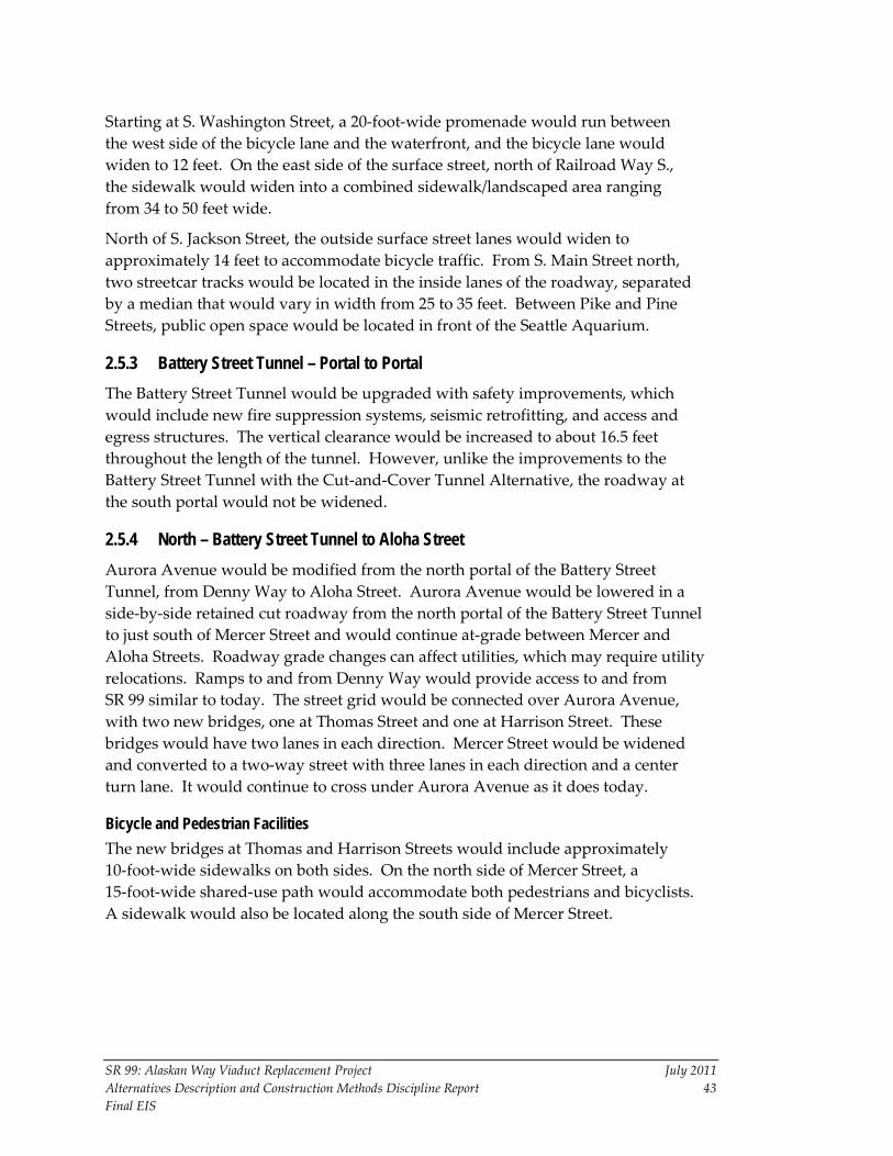
SR 99: Alaskan Way Viaduct Replacement Project July 2011 Alternatives Description and Construction Methods Discipline Report 43 Final EIS
Starting at S. Washington Street, a 20-foot-wide promenade would run between the west side of the bicycle lane and the waterfront, and the bicycle lane would widen to 12 feet. On the east side of the surface street, north of Railroad Way S., the sidewalk would widen into a combined sidewalk/landscaped area ranging from 34 to 50 feet wide.
North of S. Jackson Street, the outside surface street lanes would widen to approximately 14 feet to accommodate bicycle traffic. From S. Main Street north, two streetcar tracks would be located in the inside lanes of the roadway, separated by a median that would vary in width from 25 to 35 feet. Between Pike and Pine Streets, public open space would be located in front of the Seattle Aquarium.
2.5.3 Battery Street Tunnel – Portal to Portal The Battery Street Tunnel would be upgraded with safety improvements, which would include new fire suppression systems, seismic retrofitting, and access and egress structures. The vertical clearance would be increased to about 16.5 feet throughout the length of the tunnel. However, unlike the improvements to the Battery Street Tunnel with the Cut-and-Cover Tunnel Alternative, the roadway at the south portal would not be widened.
2.5.4 North – Battery Street Tunnel to Aloha Street Aurora Avenue would be modified from the north portal of the Battery Street Tunnel, from Denny Way to Aloha Street. Aurora Avenue would be lowered in a side-by-side retained cut roadway from the north portal of the Battery Street Tunnel to just south of Mercer Street and would continue at-grade between Mercer and Aloha Streets. Roadway grade changes can affect utilities, which may require utility relocations. Ramps to and from Denny Way would provide access to and from SR 99 similar to today. The street grid would be connected over Aurora Avenue, with two new bridges, one at Thomas Street and one at Harrison Street. These bridges would have two lanes in each direction. Mercer Street would be widened and converted to a two-way street with three lanes in each direction and a center turn lane. It would continue to cross under Aurora Avenue as it does today.
Bicycle and Pedestrian Facilities The new bridges at Thomas and Harrison Streets would include approximately 10-foot-wide sidewalks on both sides. On the north side of Mercer Street, a 15-foot-wide shared-use path would accommodate both pedestrians and bicyclists. A sidewalk would also be located along the south side of Mercer Street.

SR 99: Alaskan Way Viaduct Replacement Project July 2011 Alternatives Description and Construction Methods Discipline Report 44 Final EIS
2.5.5 Pine Street to Broad Street
Alaskan Way Surface Street The Alaskan Way surface street would be reconstructed with two lanes in each direction and left-turn pockets provided at key intersections in the north waterfront section. Instead of following the northwest-trending curve of the waterfront as it currently does, the surface street would continue straight, to the east of the public open space at the foot of the Pike Street Hillclimb, and turn back toward the waterfront between Pike and Pine Streets. The new public open space on the west side of the reconfigured surface street would consist of a wedge-shaped plaza adjacent to the Seattle Aquarium that would be approximately 90 feet wide at its broadest point.
Two streetcar tracks would be located along the centerline of the surface street, separated by a median that would vary in width from between 6 and 15 feet. On-street parking would be located on both sides of Alaskan Way.
Bicycle and Pedestrian Facilities The side-by-side bicycle path and sidewalk would continue to follow the west side of the surface street, the sidewalk broadening to 12 feet. North of Pine Street, the plaza would narrow to a 15-foot-wide waterfront sidewalk, which would widen to 25 feet north of Vine Street. Bicycle traffic would be routed to street-level bicycle lanes on each side of the surface street, varying in width from 4 to 5 feet. On the east side of Alaskan Way, a sidewalk with a width varying from 8 to 9 feet would run along the east side of the street.
Elliott Bay Seawall Replacement – Pine Street to Broad Street The Elliott Bay Seawall would be replaced between Pine and Broad Streets using soil strengthening methods, followed by the construction of new wall support structures and new face panels, approximately 12 feet landward of the existing seawall face, which would result in an increase in nearshore habitat. (See Appendix N, Wildlife, Fish, and Vegetation Discipline Report.)
The exception to this seawall work would be the section between Blanchard and Battery Streets adjacent to the Bell Harbor Conference Center (Pier 66), since this section was upgraded in the mid-1990s by the Port of Seattle. However, some soil improvements would still be necessary in front of Pier 66.
SR 99: Alaskan Way Viaduct Replacement Project July 2011 Alternatives Description and Construction Methods Discipline Report 45 Final EIS
Chapter 3 CONSTRUCTION ELEMENTS AND METHODS This chapter describes the construction process, including the anticipated methods and equipment needed to build the alternatives. This is intended to be a general description of how the alternatives would be built. As a result of the evolving design process, additional methods and approaches to the construction process may be considered.
3.1 Construction Elements Common to All Build Alternatives The following subsections describe the major construction elements that will be largely the same for all three build alternatives. Exceptions are noted in the text, where one or the other of the alternatives may have unique elements.
One construction assumption common to all three build alternatives is that construction may occur up to 24 hours per day, 7 days per week, for the entire construction period, within the permitting requirements.
3.1.1 Construction Staging Areas The following construction staging areas (shown on Exhibit 3-1) are proposed for all three build alternatives:
1. Terminal 106. Terminal 106, which is south of the S. Spokane Street Viaduct, may be used as a construction staging, contractor parking, materials fabrication, and laydown area. All materials fabrication activity would occur outside the 200-foot shoreline boundary.
2. Terminal 25. Terminal 25, which is north of S. Spokane Street near the Whatcom Railyard, could be used for contractor parking, staging, materials fabrication, and concrete debris processing (demolition materials). Both the concrete debris processing and any fabrication activities would occur outside the 200-foot shoreline boundary.
3. Washington-Oregon Shippers Cooperative Association (WOSCA) Site. The WOSCA site is located west of First Avenue S., between S. Royal Brougham Way and S. Dearborn Street. This site would be used for storage and laydown of construction materials. This site is the likely location of a temporary concrete batch plant for construction work in the south portal area, if one is deemed necessary. For the Bored Tunnel Alternative, this site would also be used to assemble the tunnel boring machine (TBM) and the temporary power substation that would be needed to power the machine’s tunnel drive.

18 NORTH END STAGING AREA
5a Pier 46
Staging Areas
15 Staging in City ROW
19
16
17 NORTH END CONSTRUCTION AREA STAGING
14 Staging in City ROW
Parking Lot
5
WOSCA Site
0 3,000
SCALE IN FEET
Exhibit 3-1Construction Staging Areas
5/17/11

SR 99: Alaskan Way Viaduct Replacement Project July 2011 Alternatives Description and Construction Methods Discipline Report 47 Final EIS
4. Pier 48. Located along Alaskan Way S. between S. Jackson and S. Washington Streets, this property is owned by the State of Washington. This property may be used for contractor parking and staging activities, such as material laydown.
5. Terminal 46. For the Bored Tunnel Alternative, the contractor would use a large portion of the northwest corner of Terminal 46, starting at the northern apron face and using a portion of the apron face at the west corner of the terminal yard. (Note: This area is larger than that described in the October 2010 Supplemental Draft EIS). This area would be used as a primary staging area for materials laydown and storage of larger construction materials such as tunnel liner segments and precast-concrete panels. Staging on this site would require (1) use of a portion of the container storage area that is currently used for refrigerated container storage, (2) demolition of a portion of the existing maintenance and repair building on this site, and (3) removal of an existing crane structure and construction of a new permanent crane maintenance building. The existing (leather) hide storage area will be relocated and will require the installation of trench drain, conveyance piping, and some pavement repair work. Use of the northwest corner of Terminal 46/Pier 46 for barging may also require other minor modifications elsewhere on the site as barging preparations are made.
WSDOT is coordinating with the Port of Seattle regarding the necessary modifications. In addition modifications would be made to the container freight ingress and egress along Alaskan Way, which is being coordinated with the Port of Seattle and the Seattle Department of Transportation (SDOT).
WSDOT is also coordinating with the Port of Seattle to address any potential effects that may result from the use of Terminal 46 for construction staging to ensure that the modifications and construction activities would not compromise the safety, access, security, and Port terminal operations.
5a. Pier 46. Pier 46 (on the northern edge of Terminal 46) is a possible location for accommodating the barging of excavated materials for off-site disposal. (Mats Mats Quarry near Port Ludlow, Washington, in Jefferson County, is the proposed location for off-site disposal.) This would include the construction of a muck handling conveyor and hopper loading system for the transfer of muck materials onto barges. Container activity on Terminal 46 would not be affected.
6. Interstate 90 (I-90) High-Occupancy Vehicle (HOV) Ramp Site. This site lies between the E-3 Busway and Sixth Avenue. On the south, this parcel

SR 99: Alaskan Way Viaduct Replacement Project July 2011 Alternatives Description and Construction Methods Discipline Report 48 Final EIS
is bounded by S. Royal Brougham Way. It would be used primarily for storage.
7. Alaskan Way S., S. King Street to S. Jackson Street. The Alaskan Way S. right-of-way between S. King Street and S. Jackson Street would be used as a construction work zone.
8. Railroad Way S. Right-of-Way. During much of the construction period, the right-of-way along Railroad Way S. under the First Avenue S. ramps would be used to accommodate south portal construction activities and construction of the tunnel operations building. During the last year of construction, the area would be used to demolish the ramps.
9. Alaskan Way S., S. Royal Brougham Way to S. King Street. This work zone and construction staging area (6-acre site) could also in part become the location of the permanent roadway connecting to the new SR 99.
10. First Avenue S. Bridge Site. This site is a triangle-shaped property bordered by West Marginal Way, Second Avenue S.W., and S.W. Michigan Street. It would be used primarily for storage.
11. Fisher Site (Fourth Avenue S., formerly the SR 519 project staging site). This WSDOT-owned site lies between Third and Fourth Avenues S. On the south and north, it lies between S. Massachusetts Street and S. Atlantic Street, respectively. It would be used primarily for storage but could be used for materials fabrication.
12. I-90 Ramp Site. This site is located between Fourth Avenue S. and the BNSF Railway tracks. The southern portion of this site is bounded by S. Royal Brougham Way. It would be used primarily for storage.
13. Sixth Avenue/Broad Street Right-of-Way. Once Broad Street is closed for the two tunnel alternatives, it could be used for construction staging and storage.
14. City of Seattle Right-of-Way. Between S. King Street and Yesler Way, portions of the existing right-of-way along Alaskan Way S. would be used for various construction activities, such as the construction of secant pile walls.
15. Construction Zone Within City Right-of-Way. North of S. King Street, this strip of right-of-way along Alaskan Way parallel to the existing viaduct would be used for demolition and removal of the viaduct structure.
16. Parking Lots Near the Battery Street Tunnel. These three small areas currently used for parking would be used for construction staging for the Battery Street Tunnel decommissioning activities (Bored Tunnel

SR 99: Alaskan Way Viaduct Replacement Project July 2011 Alternatives Description and Construction Methods Discipline Report 49 Final EIS
Alternative) and/or for materials storage for other north end construction activities for the Cut-and-Cover Tunnel Alternative or the Elevated Structure Alternative. One of these sites is currently a triangle-shaped property just west of SR 99, near the intersection of Battery Street and Western Avenue. It would be used primarily for materials storage.
17. North End Construction Staging Area. The north portal staging area is bounded by Thomas Street on the south and Broad Street on the north from Aurora Avenue to Sixth Avenue N. (except for a hotel site on Aurora Avenue). This area includes the City of Seattle Maintenance Yard, which is bounded by Harrison and Republican Streets and Sixth Avenue N. and SR 99. This area would be used for construction staging, closing and backfilling Broad Street, and TBM retrieval.
18. North End Staging Area for the Mercer Improvements. For construction of improvements on Mercer Street from Fifth Avenue N. to Dexter Avenue N., an SDOT-owned parcel on the north half of the block bounded by Mercer Street, SR 99, Roy Street, and Dexter Avenue would be used for materials storage and construction office space.
19. BNSF/Lenora Street Construction Zone. This site, which is WSDOT right-of-way, would be used for material storage for viaduct demolition and resurfacing of Alaskan Way in the last phases of construction.
20. North End Staging Area. These three small areas that are currently used for parking would be used for construction staging for the Battery Street Tunnel decommissioning activities (Bored Tunnel Alternative) or for materials storage for other north end construction activities for the Cut-and-Cover Tunnel Alternative or the Elevated Structure Alternative.
3.1.2 Construction Work Shifts If necessary to maintain the overall schedule, construction for all activities could occur up to 24 hours per day, 7 days per week, within the permitting requirements. However, the proposed construction activities and shifts are likely to vary according the location and type of construction activity.
3.1.3 Construction Haul Routes During construction of the build alternatives, City-designated truck routes would be used for transporting construction materials, oversized equipment, and spoils into and out of the construction zones. For the Bored Tunnel Alternative, WSDOT and its contractors have proposed construction haul routes that would become part of an approved traffic control plan.

SR 99: Alaskan Way Viaduct Replacement Project July 2011 Alternatives Description and Construction Methods Discipline Report 50 Final EIS
In the south section, the primary construction access to the work area (on the WOSCA site) would be from S. Atlantic Street. Construction vehicles would enter the work area via a temporary construction road that would cross the southbound off-ramp from SR 99. A temporary traffic signal would facilitate the crossing of the off-ramp. Trucks leaving the construction zone would merge with traffic on the southbound SR 99 off-ramp and turn eastbound on S. Atlantic Street. In- and outbound trucks would use Edgar Martinez Drive S. (the east extension of S. Atlantic Street) to access I-5 north and south and I-90 east and west. Over-legal loads could use First Avenue S. to Railroad Way S. to Alaskan Way S.
For haulers of construction materials and spoils, all truck route destinations would be located south of the project area. The proposed truck travel routes would be south along Alaskan Way and, in some cases, west across the West Seattle Bridge, as well as south along West Marginal Way.
In the south, some restrictions on construction haul traffic may be needed to maintain traffic operations on the temporary SR 99 off-ramp, as well as along the S. Atlantic Street corridor between East Marginal Way S. and I-90.
In the north, the potential routes being considered are I-5 to Fairview Avenue N. to Denny Way to Sixth Avenue N. to the construction zones, or I-5 to Mercer Street to the construction zones. Another potential haul route from the north portal area would use Broad Street down to Alaskan Way and then south to Terminal 46. SR 99 to and from the north is also available as a potential haul route.
3.1.4 Construction Equipment A wide variety of construction equipment, including specialized and custom-made machinery, would be needed to construct the build alternatives and demolish the existing viaduct structure. Throughout construction, materials and equipment would be stored primarily within the project area and existing road right-of-way.
Throughout construction, crews would use the following types of equipment:
• Earth pressure balance (EPB) TBM (Bored Tunnel Alternative only)
• Extended-arm trackhoes with concrete-pulverizing attachment (concrete muncher)
• Cranes
• Trucks and dump trucks
• Air compressors
• Bulldozers
• Backhoe loaders
SR 99: Alaskan Way Viaduct Replacement Project July 2011 Alternatives Description and Construction Methods Discipline Report 51 Final EIS
• Front loaders
• Excavators
• Drilling rigs (including oscillator drills)
• Vibratory pile driving equipment
• Loaders
• Forklifts and manlifts
• Jackhammers
• Various pumps, including slurry separation pumps
• Grading and paving equipment
• Compressors
• Generators
• Welding equipment
• Grouting operation equipment (mixers, pumps, and power units)
For viaduct demolition activities, crews would most likely use crunching/shearing attachments, concrete saws, concrete splitters, and cutting torches. For soil improvements, work crews would need specialty equipment such as drilling rigs for tunnel wall work, drilling rigs with mixing augers, and slurry processing equipment.
Construction for the Bored Tunnel Alternative would require additional equipment such as barges and a muck conveyor system with conveyor belts and hoppers. The need for a concrete batch plant would be determined by the contractor.
For either of the other two alternatives, other equipment would be needed for dewatering processes, such as settlement and pretreatment storage tanks.
3.1.5 Utility Relocations For the Elevated Structure Alternative, utilities that do not conflict with the construction of the elevated structure would remain in operation and be protected in place. In the south section, major utility relocations already will have taken place as part of the separate S. Holgate Street to S. King Street Viaduct Replacement Project before the beginning of construction for this alternative. The only utilities that would be located on the elevated structure would be those utility services needed for the operational roadway. North of S. King Street, it is anticipated that for the viaduct removal, utilities buried beneath the viaduct may need to be replaced, relocated, and/or protected in place. Some of these relocations or replacements may require excavation. Mitigation measures would be employed to ensure that utilities buried beneath the viaduct are not damaged during viaduct

SR 99: Alaskan Way Viaduct Replacement Project July 2011 Alternatives Description and Construction Methods Discipline Report 52 Final EIS
demolition. The surface features of existing utilities located beneath the viaduct may need to be adjusted to be flush with the new surface.
Some utilities may also need to be relocated, replaced, or protected during ground improvement activities associated with all three build alternatives. Construction of any of the build alternatives would periodically limit the occurrence of other construction activities, such as utility company construction, maintenance activities, and new service installations. Some of the other construction activities that would probably require utility relocations (temporary or permanent) are (1) construction of support walls for the tunnel portals for both the Bored Tunnel Alternative and the Cut-and-Cover Tunnel Alternative; (2) excavation for the drilled shafts for support of the Elevated Structure Alternative; and (3) construction of fill embankments or foundations or installation of soil improvements. The project will attempt to protect in place any utilities that feasibly can be protected adequately. Other utilities that may face a greater risk of damage due to the construction methods in or near the work area are likely to be relocated, and, in some cases, replaced.
3.1.6 Seattle Ferry Terminal Access During Construction The Bored Tunnel Alternative would close portions of Alaskan Way S. between S. Atlantic and S. King Streets for the first 4.5 years of construction (Traffic Stages 1 through 7) and would detour the traffic onto the East Frontage Road. Alaskan Way south of Yesler Way would be reduced to one lane in each direction, limiting the capacity for southbound exiting ferry traffic. Only a single lane of Alaskan Way would be available for ferry traffic without the proposed modifications during construction. To reduce the effects of the traffic restrictions (particularly during peak ferry travel periods) on Alaskan Way for the Seattle Ferry Terminal, temporary modifications would include a left-hand traffic signal allowing left turns for exiting traffic from the ferry terminal. To further alleviate potential queuing backups on Alaskan Way, a second northbound lane between Yesler Way and Spring Street would be added. The construction of the second northbound lane would require the removal of the waterfront streetcar tracks, signal modifications, and demolition of the elevated streetcar platform just south of Spring Street. This additional northbound lane could also facilitate the viaduct demolition and the Alaskan Way reconstruction.
For access to the Seattle Ferry Terminal, ferry-bound traffic would be routed northbound on Alaskan Way using the right-of-way under the existing viaduct up to about University Street, and then it would loop back southbound to access the ferry terminal.

SR 99: Alaskan Way Viaduct Replacement Project July 2011 Alternatives Description and Construction Methods Discipline Report 53 Final EIS
3.2 Bored Tunnel Alternative – Construction Methods for Major Elements
3.2.1 Construction Risks and Ground Improvement Methods Tunneling would be undertaken with best-available tunneling technology to minimize ground settlement. A combination of ground improvement methods, which are discussed in the following subsections, would be used before and during the tunneling activities to protect existing structures and underground utilities from potential ground subsidence as well as to strengthen the ground mass so that it can better accommodate tunnel construction.
More extensive ground improvements would be for the construction of the south portal and along the southern portion of the tunnel alignment where the predominant soils are fill material. The area south of University Street, primarily between Yesler Way and Madison Street, is more vulnerable to ground settlement because of the soil types found in that area and the relatively shallow depth of the tunnel. The area near the south portal where compensation grouting is likely to be needed is shown in Exhibit 3-2, along with a plan view of the grouting process at each grouting shaft. There may be a few small locations in the north portal area where settlement mitigation measures using ground improvement may also be needed.
Ground improvement would likely be performed along the tunnel alignment to stabilize soft soils around the tunnel and mitigate potential ground loss. The minimization of ground settlement risks posed by the tunnel work, such as sinkholes in streets or on private property, or damage to utilities on private property, is a primary goal of the design for the tunnel construction. Ground improvements, such as those described in the following subsections (e.g., compensation grouting and compaction grouting), would also be used as advance mitigation to prevent damage to utilities due ground settlement before the tunnel boring begins. Other potential methods for ground improvements are ground anchors to be placed at intervals to provide uplift resistance from the water table below in the southern portion of the tunnel alignment, where the tunnel is below the water table and has limited cover above. Refer to Appendix P, Earth Discipline Report, for a more detailed discussion of ground improvements and potential effects.
Although extensive planning and design measures are being undertaken to prevent ground subsidence resulting from the Bored Tunnel Alternative and the Cut-and-Cover Tunnel Alternative, some unanticipated settlement could occur. If unanticipated settlement occurs, emergency measures would be necessary to repair damage or minimize further settlement. These measures could include lane and/or sidewalk closures or accessing basements of adjacent buildings, as well as emergency utility repair for electrical systems and/or customers.
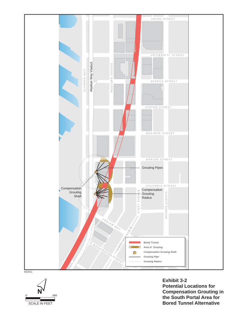
SE
CO
ND
AV
EN
UE
AL
AS
KA
N W
AY
WE
ST
ER
N A
VE
NU
E
FIR
ST
AV
EN
UE
C O L U M B I A S T R E E T
M A R I O N S T R E E T
M A D I S O N S T R E E T
S P R I N G S T R E E T
S E N E C A S T R E E T
U N I V E R S I T Y S T R E E T
U N I O N S T R E E T
FI R
ST
AV
EN
UE
S
S W A S H I N G T O N S T R E E T
Y E S L E R W A Y
Ala
skan
Way
Via
duct
Compensation Grouting Radius
Bored Tunnel
Area of Grouting
Compensation Grouting Shaft
Grouting Pipe
Grouting Radius
CompensationGrouting
Shaft
Grouting Pipes
0 340
SCALE IN FEET
Exhibit 3-2Potential Locations forCompensation Grouting inthe South Portal Area forBored Tunnel Alternative
6/13/11

SR 99: Alaskan Way Viaduct Replacement Project July 2011 Alternatives Description and Construction Methods Discipline Report 55 Final EIS
Compaction Grouting Compaction grouting is a process in which a highly viscous grout is injected into the soil mass. The grout does not penetrate the pores as with permeation grouting; instead it forms a grouted “bulb” within the soil mass, displacing the natural soil and consolidating and condensing it in the process. A single bulb has a limited volume and area of soil improvement. However, multiple bulbs can be placed adjacent to one another to achieve the desired results. It is especially useful in loose, granular soils that densify or compact easily and quickly.
Compaction grouting would involve the injection of grout above the tunnel crown as the tunnel bore advances forward longitudinally. The grout densifies the soil profile overlying the tunnel’s crown and replaces some of the lost ground, thereby preventing potential settlement (or sinkholes) from propagating upward to the surface.
Compensation Grouting Compensation grouting would be performed to mitigate ground loss during tunneling beneath the structures where settlement is anticipated or detected during construction of the bored tunnel. Grout is injected into the ground beneath the foundations of existing structures, forming a grout bulb. The grout displaces the soil and has the potential for uplifting the foundation and restoring ground support. For sensitive structures where settlement is anticipated, grout injection pipes could be installed before construction begins (Exhibit 3-3). Settlement monitoring could be performed as construction progresses, and then, if ground settlement is detected, the pre-installed pipes could be used to inject the grout and maintain the structural alignment. If the grout is not installed in time, settlement of the structure could occur. Also, if the grout injection pressure is not carefully controlled, excessive uplift or lateral pressure against the foundations could damage the structure.
Compensation grouting is generally performed using large-diameter drilled shafts below ground (Exhibit 3-3).
The current proposal for the grouting procedures in the south end would use two large-diameter (approximately 15-foot) access shafts. The shafts would be drilled into the ground to facilitate the installation of an array of grout tubes under the existing building foundations. These shafts would extend to the base of the existing pile foundations, about 40 feet below grade. Grouting operations (mixers, pumps, and power units) would be located at the surface to service the drilling of the grout tubes. The access shafts are planned for the southern portion of the project area (primarily south of Seneca Street), where the soils are weaker and less dense.

GroutInjectionPipes
Exhibit 3-3Compensation Grouting
5/17/11

SR 99: Alaskan Way Viaduct Replacement Project July 2011 Alternatives Description and Construction Methods Discipline Report 57 Final EIS
The key to effective compensation grouting is to carefully monitor both the structure and any ground movements to optimize the timing and quantities of injected grout. Through reuse of pre-installed grout placement pipes, grout can be injected before, during, and after the tunnel drive.
Jet Grouting Another soil improvement method that could be used is jet grouting. This is a process in which cement grout is injected deep into weak or loose soils and then mixed to strengthen and stabilize the soil. Exhibit 3-4 depicts the jet grouting process.
The Bored Tunnel Alternative’s alignment would pass under the Western Building, a historic building in the Pioneer Square Historic District that has been identified as being in poor structural condition. This building will be protected and reinforced during construction. The parking lot immediately south of the Western Building would be used for equipment and materials for the stabilization and protection procedures, estimated to take between approximately 12 to 20 months.
Western Building and Stabilization and Protection Methods
The protection and stabilization approach entails strengthening the building’s foundation with micropiles and grade beams, or the construction of a system of reinforced concrete walls, or a combination of these methods. The existing cracked column and beams would be epoxy grouted and wrapped. An exterior steel frame with interior shoring and cross bracing would be built. Compensation grouting would also be performed with monitoring to limit any building settlement to 0.5 inches.
Ground Freezing Artificial ground freezing is a process by which heat is extracted from a water-saturated soil mass, temporarily converting the interstitial pore water to ice, resulting in a consolidated soil mass as long as it remains frozen. The heat extraction is accomplished by installing freeze pipes into the soil mass to be frozen and then circulating a refrigerant fluid to extract the heat. Under normal conditions, a saline solution with a freezing point below that of pure water is used. Liquid nitrogen can be used for saline groundwater conditions, where groundwater is moving under a slight hydraulic gradient, or where a “quick freeze” is desired. The freeze can be maintained as long as the temporary foundation support is required.
Although ground freezing is applicable to all soil types, it is potentially problematic in some soils. Since water expands as it freezes, free water must be allowed to escape from the pore space as the ice forms; otherwise, ice lenses will form and result

Jet Grouting
Deep Soil Mixing
Soil Improvement Methods
6/13/11
Exhibit 3-4Jet Grouting and Deep Soil Mixingfor Cut-and-CoverTunnel andElevated Structure Alternatives

SR 99: Alaskan Way Viaduct Replacement Project July 2011 Alternatives Description and Construction Methods Discipline Report 59 Final EIS
in ground heave. In coarse- to fine-grained granular soils, this is usually not an issue, because the soil is permeable enough to allow free water to escape. As soils become finer grained (in the silt sizes), the permeability is low enough that free water cannot easily escape; in some cases, capillary action can attract free water to the ice crystals. Either phenomenon results in the formation of ice lenses that result in ground heave. In clays, free water cannot escape, but capillary action is reduced. Depending on the natural water content of the clay, some heave potential still exists due to ice formation and expansion. There is a risk that any buried utilities that carry water (such as water and sewer lines) could also freeze if they are within the zone of formation of the frozen ground block.
Underpinning Underpinning is a traditional structural modification process by which the foundations of an existing structure are temporarily (sometimes permanently) structurally supported by alternative support elements. The objective is to maintain the structural integrity and vertical position of the existing structure during excavation for a new structure.
Typical underpinning methods include temporary timber cribbing beneath existing foundations, ground improvement with grout or ground freezing beneath the existing foundations, or new structural elements such as pin piles (or micropiling) beneath the existing foundations. The selection of an appropriate underpinning solution is a function of the size (weight) and geometry of the structure requiring temporary support, the work space available, the site-specific ground and groundwater conditions, the availability of specialty equipment and local labor, the length of time the supplemental foundation support is required, and the cost and schedule to construct the underpinning solution.
3.2.2 South Portal Area Construction One of the risk reduction measures planned for the construction of the bored tunnel launching area is the construction of a “protection box” of secant piles, around the initial 800 feet of the tunnel drive between approximately S. Dearborn and S. Main Streets. This protection box would be built to reduce the risks of settlement and help isolate the TBM from soil and groundwater as it begins its drive underground. At the beginning of the tunnel, there would be less ground above the TBM and the crown of the tunnel that is being formed, and the probability of ground deformation would be greater. A safe haven (a preplanned zone of treated ground) would be established at the end of this section to provide a safe zone for construction staff performing inspections after the startup of the TBM and for crew training. This safe haven would help to isolate the TBM from the soil and groundwater when it is stationary.

SR 99: Alaskan Way Viaduct Replacement Project July 2011 Alternatives Description and Construction Methods Discipline Report 60 Final EIS
Beyond the launching area north of S. King Street, slurry or secant piles with a diameter of approximately 5 feet would be pre-installed along both sides of the proposed tunnel alignment to just south of Yesler Way. The total length of these walls would be approximately 3,000 linear feet. Once the walls have been installed, the TBM excavation operation would begin along Alaskan Way.
The cut-and-cover tunnel segments would be constructed between slurry or secant piles installed to varying depths of approximately 12 feet to a maximum of 90 feet. Temporary tiebacks (and/or internal bracing struts) would also be installed for support.
The current plan is to support and protect in place as many of the utilities in the construction area as possible. However, it would be necessary to temporarily relocate some utilities and replace them in their current location or permanently relocate them.
The south portal design includes the construction of a tunnel operations building and ramps providing north- and southbound on and off movements to and from SR 99. Construction durations for this activity are based on the assumption of two 8-hour shifts, each working 5 days per week, but the shifts could total up to 24 hours per day, 7 days per week, if necessary to maintain schedule.
Other work in the south portal area would include construction of foundations for structures, grading for roadways, trenching for utilities, ground improvements, placement and compaction of fill, and removal of existing subsurface structures. In shallow excavation areas, such as utility trenches, temporary shoring may be used to provide excavation support. For the two tunnel alternatives, construction dewatering would likely be required during construction to control groundwater flow into the excavations that extend below the water table.
Concurrent with ground improvement and settlement mitigation operations in the south end, typical mobilization and staging work would be conducted on the WOSCA site, extending from S. Royal Brougham Way to S. Dearborn Street. General construction best management practices (BMPs) would be in place for these activities.
3.2.3 Bored Tunnel Construction For the Bored Tunnel Alternative, a thick reinforced-concrete slab approximately 400 feet long would be installed to support the concrete cradle that would, in turn, support the TBM. This area, located west of the viaduct, is where the assembly and launching of the TBM would take place. The WOSCA site would be used to support the tunnel boring operations. Upon completion of the bored

SR 99: Alaskan Way Viaduct Replacement Project July 2011 Alternatives Description and Construction Methods Discipline Report 61 Final EIS
tunnel construction, the structures connecting the tunnel to SR 99 and the surrounding surface streets would be completed.
The current plan is to initiate tunnel construction from the south portal (just south of S. King Street), excavate northward under Alaskan Way, cross under the existing viaduct to follow a large curve beginning just south of S. Washington Street, and then pass under Western Avenue parallel with First Avenue. The tunnel would be about 215 feet below the existing ground level at its deepest point, near Virginia Street. The tunnel would then rise as it continues north under First Avenue to near Stewart Street, follow another large curve to the north, and cross under the Belltown neighborhood at a diagonal, emerging at about Thomas Street. After a few hundred feet, the tunnel would transition back to a cut-and-cover section north of Thomas Street. This section would unbraid from the stacked configuration to a side-by-side roadway to match the existing grade of Aurora Avenue near Mercer Street.
The bored tunnel would contain two roadway decks, with the southbound roadway above and the northbound roadway below. Each roadway deck would convey two lanes of traffic.
Construction durations for this activity are based on the assumption of three 8-hour shifts, each working 6 days per week, and a seventh day for TBM maintenance.
This work would include the construction of a slurry or secant pile wall with temporary tiebacks (and/or internal bracing struts) to support an open-cut excavation. This excavation would allow for construction of the ramps and mainline roadways that would connect the bored tunnel to SR 99. See Section 3.2.1 for a discussion of potential ground improvement methods that could be used to strengthen existing soils, as required for portal and tunnel construction activities and long-term operation. Some of the early soil improvement work would be undertaken to reduce the risks of settlement of existing buildings in the areas where the soil types warrant additional strengthening. This is discussed in the paragraphs below, and greater detail regarding the geology and soils in the project area is provided in Appendix P, Earth Discipline Report.
Ground replacement and ground improvement methods are being considered to strengthen soils sufficiently to accommodate the construction of the proposed structures, particularly in the south portal area where the soil is mostly fill material. To initiate tunneling for the Bored Tunnel Alternative, it would be necessary to construct a deep, long, braced excavation area with a vertical headwall where the tunneling would start, with a back slope to grade. A minimum cover of at least 25 feet of stiff ground (roughly half the tunnel diameter) is required above the TBM to safely begin tunneling. Ground

SR 99: Alaskan Way Viaduct Replacement Project July 2011 Alternatives Description and Construction Methods Discipline Report 62 Final EIS
investigations at this location indicate the presence of about 30 feet of poor ground consisting of loose sand, fill, timber, and other artificial materials overlying very dense silty sand to gravel.
To alleviate disruption and shorten the duration of planned utility outages and street closures in the area, utilities would be protected in place where possible. However, some may need to be relocated or replaced if they cannot be protected in place.
Temporary excavation support walls (shoring) must be installed before beginning any excavation. Shoring walls must be laterally supported (using either internal struts or tiebacks) as the excavation is progressively deepened to prevent instability and control settlement at the sides of the cut. The method of shoring would depend on the depth of excavation and the corresponding ground conditions.
The construction approach that offers the least disruption to the Pioneer Square and stadium area is the bored tunnel alignment. Several construction approaches will be considered, with the objective of minimizing utility relocations, decreasing the duration of traffic disruption, and reducing risks relating to poor soil conditions to facilitate a safer start for the tunneling process.
As the project develops and the construction methods become more established, strategies will be developed to ensure local connectivity and access to buildings and businesses by pedestrians, bicyclists, motorists, and movers of freight. In addition, methods to ensure access to public facilities and utilities would be developed for those not relocated before construction.
Portal Entry Construction The cut-and-cover section to be built for the portal entry points at both ends of the tunnel would involve construction of a box structure placed within a trench excavation. The excavation would subsequently be backfilled, followed by restoration of disturbed surface features, such as streets, utilities, and amenities (e.g., sidewalks and street furniture).
As both portals would be built in a dense urban setting, underground work using the cut-and-cover method would entail the following activities:
• Relocating utilities and rerouting traffic • Mitigating construction-generated effects (e.g., noise, dust, and traffic
congestion) • Modifying access for commercial businesses and nearby residential uses • Localized disruption of some transit routing
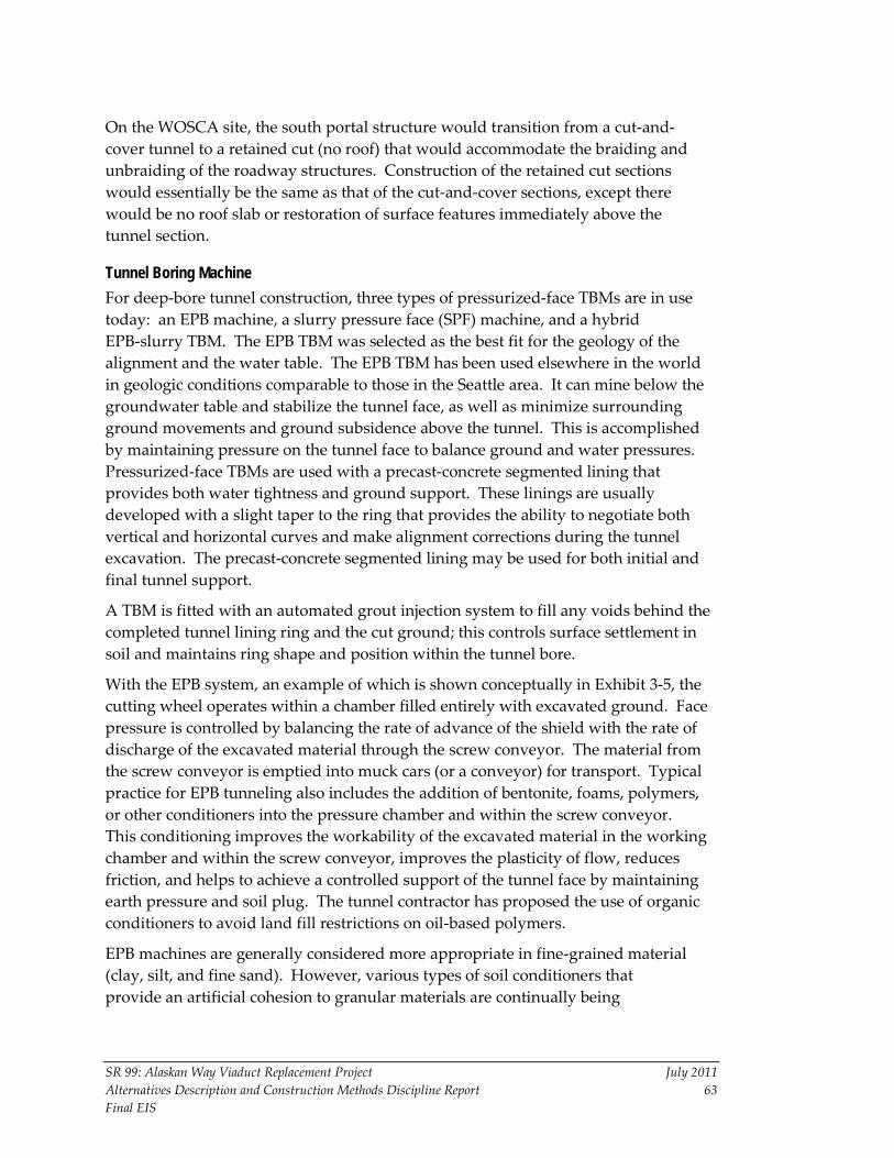
SR 99: Alaskan Way Viaduct Replacement Project July 2011 Alternatives Description and Construction Methods Discipline Report 63 Final EIS
On the WOSCA site, the south portal structure would transition from a cut-and-cover tunnel to a retained cut (no roof) that would accommodate the braiding and unbraiding of the roadway structures. Construction of the retained cut sections would essentially be the same as that of the cut-and-cover sections, except there would be no roof slab or restoration of surface features immediately above the tunnel section.
Tunnel Boring Machine For deep-bore tunnel construction, three types of pressurized-face TBMs are in use today: an EPB machine, a slurry pressure face (SPF) machine, and a hybrid EPB-slurry TBM. The EPB TBM was selected as the best fit for the geology of the alignment and the water table. The EPB TBM has been used elsewhere in the world in geologic conditions comparable to those in the Seattle area. It can mine below the groundwater table and stabilize the tunnel face, as well as minimize surrounding ground movements and ground subsidence above the tunnel. This is accomplished by maintaining pressure on the tunnel face to balance ground and water pressures. Pressurized-face TBMs are used with a precast-concrete segmented lining that provides both water tightness and ground support. These linings are usually developed with a slight taper to the ring that provides the ability to negotiate both vertical and horizontal curves and make alignment corrections during the tunnel excavation. The precast-concrete segmented lining may be used for both initial and final tunnel support.
A TBM is fitted with an automated grout injection system to fill any voids behind the completed tunnel lining ring and the cut ground; this controls surface settlement in soil and maintains ring shape and position within the tunnel bore.
With the EPB system, an example of which is shown conceptually in Exhibit 3-5, the cutting wheel operates within a chamber filled entirely with excavated ground. Face pressure is controlled by balancing the rate of advance of the shield with the rate of discharge of the excavated material through the screw conveyor. The material from the screw conveyor is emptied into muck cars (or a conveyor) for transport. Typical practice for EPB tunneling also includes the addition of bentonite, foams, polymers, or other conditioners into the pressure chamber and within the screw conveyor. This conditioning improves the workability of the excavated material in the working chamber and within the screw conveyor, improves the plasticity of flow, reduces friction, and helps to achieve a controlled support of the tunnel face by maintaining earth pressure and soil plug. The tunnel contractor has proposed the use of organic conditioners to avoid land fill restrictions on oil-based polymers.
EPB machines are generally considered more appropriate in fine-grained material (clay, silt, and fine sand). However, various types of soil conditioners that provide an artificial cohesion to granular materials are continually being
EPB machines loosen the soil at the tunnel face by means of the tools on the rotating cutting wheel (1). The soil then passes through the cutting wheel openings into theexcavation chamber (2), where it is mixed with the existing plastic soil. The force ofthe thrust cylinders (4) is transferred to the plastic soil via the pressure bulkhead (3),thus controlling the movement of soil from the tunnel face into the excavation chamber.The excavated material is conveyed from the pressurized excavation chamber to thetunnel, which is under atmospheric pressure, by the screw conveyor (5). Directly behindthe shield, the tunnel (7) is lined with segments by means of an erector (6).
1
2
3
4
56
7
Exhibit 3-5Typical Earth Pressure BalanceTunnel Boring Machine
6/8/11
Source: Sivalingam and Klados 2006.

SR 99: Alaskan Way Viaduct Replacement Project July 2011 Alternatives Description and Construction Methods Discipline Report 65 Final EIS
developed and improved. These soil conditioners allow EPB machines to be used in more granular soil types. EPB TBMs are commonly fitted with cutting disks to excavate through rock materials, including cobbles and boulders.
Bored Tunnel Muck Removal The tunneling contractor would choose the method most advantageous for removing the excavated spoil materials (muck) generated during the tunneling work. Spoils would be removed through the south portal area by means of hoppers and conveyors and transported to a staging area for stockpiling before being transported by truck or barge to the Mats Mats Quarry disposal site in Port Ludlow.
The conveyor system transporting the muck from the tunnel would be enclosed once the muck leaves the bored tunnel, reducing the potential for fugitive dust and noise, as well as improving the visual quality of the work area. The use of barges for muck and spoils transport would greatly reduce the number of project-related truck trips on city streets. The number of truck trips that would be necessary to transport the volumes of tunnel muck is estimated at approximately 600 truckloads per day.
Bored Tunnel Construction Activities The bored tunnel would have an outside diameter of approximately 56 feet and would be excavated by a pressurized-face TBM. The TBM with trailing gear would likely measure at least 400 feet in length and approximately 56 feet in height. The tunnel would be lined with precast-concrete segments as the tunnel is excavated. Two levels of roadway deck would be installed in the tunnel to support two lanes of traffic in each direction.
A project work site would be established on the WOSCA site to support TBM excavation and road deck construction. The facilities on the WOSCA site would include laydown areas for materials, maintenance workshops, storage areas for excavated spoils and precast-concrete segments, along with parking and field offices for contractors’ and owner’s on-site personnel.
The WOSCA site would also be the location of a temporary electrical substation, and electrical systems in the area would be extended to this substation to provide power to the TBM. This extension of electrical systems to feed the TBM would require improvements to the Seattle City Light (SCL) electrical distribution system facilities outside the project area to bring the necessary service (with electrical loads estimated to be between 20 to 25 megavolt amperes) into the temporary substation. The footprint of the temporary TBM electrical substation on the WOSCA site would be approximately 75 feet by 125 feet, and the structure would be no more than two stories high.

SR 99: Alaskan Way Viaduct Replacement Project July 2011 Alternatives Description and Construction Methods Discipline Report 66 Final EIS
Bored tunnel construction would likely occur in the following sequence of activities:
1. Procure TBM.
2. Set up staging areas to support tunnel excavation and internal construction.
3. Excavate tunnel; install permanent lining system for ground support as excavation proceeds.
4. Construct internal structure and configuration of roadways, egress passages, and ventilation ducts.
5. Install embedded components for tunnel systems, including fire and life safety and directional information signage. Fire and life safety systems for the tunnel include power, lighting, ventilation, fire alarm, sprinkler system, traffic signals, and communications.
The TBM and its trailing gear would be assembled at the bottom of the cut-and-cover tunnel excavation. Driving the TBM through the proposed tunnel alignment is estimated to take approximately 1 year, assuming an average rate of advancement of approximately 30 feet per day. This assumes three 8-hour shifts per day, 6 days per week. Excavating a 56-foot-diameter bore at 30 feet per day would produce an average of approximately 2,600 cubic yards of material per day. If trucks are used, the spoils would fill approximately six trucks per hour, assuming 18 cubic yards per truck. At the completion of the tunnel drive, the TBM and associated trailing gear would be dismantled and removed from the north end of the tunnel. The current plan is to complete the bored tunnel excavation and remove the TBM before starting construction of the internal roadway structure and emergency escape facilities.
One possible method for constructing the tunnel’s internal walls and roadway decks would be to use a combination of cast-in-place concrete and precast-concrete components fabricated off site and brought in from both ends of the tunnel, with assembly staged from a specially fabricated moving rig and working platform called a “jumbo.” The interior of the tunnel structure would be supported on the precast-concrete tunnel liner segments. The lower roadway slab and walls would sit on cast-in-place concrete supports.
Internal Tunnel Construction
After the TBM is removed from an extraction pit at the north end of the tunnel, precast-concrete panels for the lower roadway deck would be installed. The panels would be concurrently loaded from the north and south ends of the tunnel, and work would proceed toward the middle of the tunnel. Both cast-in-place and precast-concrete components would then be installed for the tunnel’s
SR 99: Alaskan Way Viaduct Replacement Project July 2011 Alternatives Description and Construction Methods Discipline Report 67 Final EIS
side walls, emergency stair enclosures, and the upper roadway deck. After these internal structures have been completely installed, components for the mechanical, electrical, and control/instrumentation systems would be installed throughout the bored tunnel and portals.
The proposed design for the roadway configuration in the bored tunnel provides an 8-foot-wide west shoulder, a 2-foot-wide east shoulder, 11-foot-wide lanes, and a 15.5-foot vertical clearance height on each roadway level. The interior design also has taken into account the need for emergency egress and providing for any emergency situations.
Bored Tunnel Design and Safety Measures
The design providing one 8-foot-wide shoulder in the bored tunnel (in each direction) is considered reasonable for vehicles to pull off the road in case of emergency. The bored tunnel is also subject to the requirements of the Americans With Disabilities Act (ADA), and the design team has coordinated closely with the Seattle Fire Department to develop safety measures to ensure that the tunnel meets all applicable safety criteria and that appropriate emergency procedures are in place for emergency situations. The emergency procedures should include a detailed emergency response plan that involves all first responder agencies, such as the Washington State Patrol, the Seattle Police Department, and the Seattle Fire Department. They also include established procedures to assist those who may be incapacitated or those with mobility impairments.
Those who would be unable to use the stairs to exit the tunnel would wait in the enclosed, protected refuge area for assisted rescue. The refuge areas and egress corridor provide a safe environment for evacuees; they are ventilated separately with fresh air, isolated from the roadway traffic and emergencies by continuous walls, and accessible without stepping over a curb.
3.2.4 North Portal Area Construction Tunnel boring operations would end just north of Thomas Street. An open-cut extraction pit at the beginning of the cut-and-cover segment would be excavated to remove the TBM, and the machine would be dismantled and extracted at this location. This excavation would be supported with conventional tied-back soldier walls. At the end of the bored tunnel, SR 99 would begin to unbraid and transition to a cut-and-cover segment as the roadways emerge from the bored tunnel between Thomas and Harrison Streets. The permanent cut-and-cover structure would consist of cast-in-place concrete slab walls and cover slabs. Construction of the north portal would begin with retaining walls constructed along the eastern and western boundaries of the project area. The interior structures housing the northbound and southbound roadway decks and connections to the tunnel ventilation structures would be built within the excavation.

SR 99: Alaskan Way Viaduct Replacement Project July 2011 Alternatives Description and Construction Methods Discipline Report 68 Final EIS
Utility relocations would be required for surface street improvements in the north section.
North Portal Tunnel Operations Building The tunnel operations building would be built just east of the TBM extraction pit. The building would be located between Thomas and Harrison Street on the east side of Sixth Avenue N. The location and design concept for the fan rooms and ventilation structures associated with the north tunnel operations building allow these prominent features to serve as “beacons” or landmarks to travelers as they approach the north portal area.
3.2.5 Viaduct Demolition The Bored Tunnel Alternative includes the demolition and removal of the existing viaduct. The viaduct columns would be removed to an estimated depth of 5 feet below existing grade. The activities associated with viaduct demolition and removal are assumed to require two 8-hour shifts per day, 6 days per week.
All utilities attached to the viaduct and expected to remain in service would need to be relocated before the viaduct is demolished, as described in Section 3.1.5. For the viaduct removal, it may be necessary to replace the utilities that are buried beneath the viaduct. Some of these relocations or replacements may require excavation. Mitigation measures would be used to ensure that utilities that do remain buried beneath the viaduct are not damaged during demolition.
For the demolition and removal of the viaduct structure between S. King Street and the Battery Street Tunnel, concrete munchers would be used exclusively in locations adjacent to existing businesses or any residential uses, to control the size and dispersion of concrete debris. To protect any live underground utilities within the footprint of the existing viaduct, either timber mats or gravel bedding would be used. Water would be used to control fugitive dust created during demolition. Signs, fences, traffic control flaggers, and possibly uniformed police officers may be used to separate pedestrians and vehicles from the construction work zone. Materials resulting from viaduct demolition would be broken concrete and severed reinforcing steel. A smaller concrete-breaking hammer would be used to further separate the concrete from the reinforcing steel, and these materials would be placed in separate stockpiles.
Some of the concrete rubble may be recycled and used to fill the Battery Street Tunnel during the decommissioning process. The remaining demolition debris would likely be trucked to local disposal sites or recycled for use on other projects, although some portion of the debris could be transferred to an active quarry site (Mats Mats Quarry near Port Ludlow, Washington, in Jefferson County, as one possible location).
SR 99: Alaskan Way Viaduct Replacement Project July 2011 Alternatives Description and Construction Methods Discipline Report 69 Final EIS
The fleet of demolition equipment to be used for the viaduct removal would consist of two extended-arm trackhoes with a concrete-pulverizing attachment (concrete muncher), two trackhoes with a concrete-breaking hammer attachment, a 60-foot-reach manlift, a 60-ton-capacity support crane, a 10-ton-capacity forklift, two track-mounted backhoes, and several pickup trucks and dump trucks.
In all cases, demolition is currently proposed to occur concurrently in about two-block segments at a time. This means that up to four blocks along the viaduct alignment could be under demolition at a given time.
3.2.6 Battery Street Tunnel Decommissioning The decommissioning of the Battery Street Tunnel would require disconnecting the power, water, and drainage lines; filling the void space with suitable material (potentially recycled concrete rubble from the demolition of the viaduct); closing all of the street access vents; and blocking the portals at both ends of the tunnel. The necessary utilities would be reconnected as required.
Small utility equipment such as excavators and loaders would be used during the decommissioning and restoration of any of the utilities. Some concrete pavement breaking would be required, and some evening or weekend street closures may be necessary to support this operation. Most of the void space would be filled with suitable material (either imported fill or rubble debris generated from the viaduct demolition) compacted to a designated value. The remaining space would be capped with a fluid material such as controlled-density fill. Earth-moving equipment such as loaders, graders, compactors, and haul trucks would transport, spread, and compact the backfill material into the Battery Street Tunnel. The fluid cap would be placed by concrete pump trucks that would be staged either at the portals or along the surface street above (Battery Street).
3.2.7 Surface Street Improvements and Restoration of Utilities Landscaping, trails, and sidewalk improvements would be incorporated into the reconstruction of surface roadways and the intersections between First Avenue S. and Alaskan Way S.
Aboveground utilities would be replaced, and other utilities would be relocated before street reconstruction. Any underground utilities would also be installed before surface street restoration. Construction would affect SCL’s transmission lines, network, and distribution systems, as well as water lines and mains, sanitary sewer and storm drains, natural gas lines, and telecommunications systems.
For greater detail regarding the construction effects and restoration activities related to the utilities in the south and north portal areas, see Section 6.2.2 of Appendix K, Public Services and Utilities Discipline Report.

SR 99: Alaskan Way Viaduct Replacement Project July 2011 Alternatives Description and Construction Methods Discipline Report 70 Final EIS
New intersections constructed at John, Thomas, and Harrison Streets would cross the Aurora Avenue surface street. Mercer Street would be widened between Fifth Avenue N. and Dexter Avenue N., and SR 99 would be raised to provide vertical clearance for the Mercer Street crossing.
The existing ramps at Denny Way would be replaced by ramps at Harrison Street. The new northbound SR 99 off-ramp would exit onto a rebuilt Republican Street that would connect with Dexter Avenue N. The new southbound on-ramp to SR 99 would be on Sixth Avenue N. between Harrison and Mercer Street.
The existing retained cut along Mercer Street would be widened from four to six lanes to accommodate two additional lanes of traffic. Construction of the ramp connection and the roadway widening would require demolishing portions of the existing retaining walls at Mercer and Broad Streets. New retaining walls would be needed along the south side of Mercer Street from about Fifth Avenue N. to SR 99 and along the west side of Sixth Avenue between Mercer Street and Harrison Street because of additional development planned by the Gates Foundation Campus that would lower the grade south of Mercer Street.
3.3 Cut-and-Cover Tunnel Alternative Construction Methods
3.3.1 South – S. Royal Brougham Way to S. King Street Utility relocations would be required prior to much of the construction work in the south section. The current plan is to support and protect in place as many of the utilities in the construction area as possible. However, it would be necessary to temporarily relocate some utilities and replace them in their current location or permanently relocate them.
Slurry walls or secant piles with a diameter of approximately 5 feet would be used to support the excavation. These secant pile walls would be installed along both sides of the proposed tunnel alignment from S. King Street to about S. Washington Street. Once the secant piles are installed, the excavation operation would begin, down to varying depths of approximately 12 feet to a maximum of 90 feet. Temporary tiebacks and/or internal bracing struts would be installed for additional support.
The south portal design includes the construction of a tunnel maintenance building and ramps providing northbound on, northbound off, southbound on, and southbound off movements to and from SR 99. Construction durations for this activity are based on the assumption of two 8-hour shifts, each working 5 days per week, but the shifts could total up to 24 hours per day, 7 days per week if necessary to maintain the schedule.
Other work in the south portal area would include construction of foundations using structural retaining walls for the portal structures, grading for roadways,

SR 99: Alaskan Way Viaduct Replacement Project July 2011 Alternatives Description and Construction Methods Discipline Report 71 Final EIS
trenching for utilities, ground improvements, placement and compaction of fill, and removal of existing subsurface structures. In shallow excavation areas, such as utility trenches, temporary shoring may be used to provide excavation support. Construction dewatering would likely be required during construction to control groundwater flow into the excavations that extend below the water table.
Seawall Construction With Shared Tunnel Wall The Cut-and-Cover Tunnel Alternative would replace the seawall from S. Jackson Street up to Broad Street. Between S. Jackson Street and S. Washington Street, soil improvements and new face paneling would replace the failing bulkhead at Pier 48. From S. Jackson Street to Union Street, the seawall would be replaced with the west wall of the tunnel.
Between S. Jackson Street and Yesler Way, the new seawall would be constructed in approximately the same location as the existing seawall. North of Yesler Way, the new seawall would gradually move toward the east approximately 10 to 12 feet behind (landward of) the existing seawall.
Soil Improvement Soil (or ground) improvement would be conducted along the western side of SR 99 using several potential methods, including jet grouting or deep soil mixing. Jet grouting is a process by which cement grout is injected into weak soils and then mixed to strengthen and stabilize the soil (see Exhibit 3-4). Jet grouting would create a solid block of improved soil behind the existing seawall that is embedded into the competent soil layer of glacial till underlying the waterfront area. For greater detail regarding these soil improvement methods, see Appendix P, Earth Discipline Report.
3.3.2 Central – S. King Street to South Portal of Battery Street Tunnel The installation of piles would be required to construct the temporary bridge between Pier 48 and the Seattle Ferry Terminal at Colman Dock, and the two pedestrian access bridges in the central waterfront that would provide access between the piers and the waterfront businesses. This work would take place in the latter half of Traffic Stage 1, and would be completed around the fish window restrictions, as specified in the permit conditions.
A variety of pile types and methods of installation could be used. Details regarding the pile types and installation methods are not currently available. However, mitigation measures would be implemented if any impact methods are used.
The temporary ferry access bridge would be approximately 300 feet long and would require in-water pile-supported foundations with above-water crossbeams in several locations. This work would involve the use of a barge and crane, a support barge, and pile-driving equipment.

SR 99: Alaskan Way Viaduct Replacement Project July 2011 Alternatives Description and Construction Methods Discipline Report 72 Final EIS
Seawall Construction The Cut-and-Cover Tunnel Alternative would replace the seawall from S. King Street to Broad Street. Between S. King Street and S. Washington Street, soil improvements and new face paneling would replace the failing bulkhead at Pier 48. From S. Washington Street to Union Street, the seawall would be replaced with the west wall of the tunnel.
Between S. Jackson Street and Yesler Way, the new seawall would be constructed in approximately the same location as the existing seawall. North of Yesler Way, the new seawall would gradually move toward the east. Between Yesler Way and Madison Street, the new seawall face would be approximately 10 to 12 feet behind (landward of) the existing seawall.
In most of the area from just north of Union Street up to Broad Street, the existing seawall is Type A Seawall. The seawall would be rebuilt with a new face panel, a reinforced concrete L-wall support structure, and a cantilevered sidewalk. In the area near Pier 66, between Blanchard and Battery Streets, only soil improvements would be needed. Rebuilding the seawall from Union Street to Broad Street would take about 18 months. This would likely use L-wall construction with cantilevered sidewalk sections that would overhang Elliott Bay.
The soils behind the seawall would likely be strengthened by means of jet grouting. The existing exposed sheet pile wall would be removed by cutting it off at the mudline and replacing it with a new reinforced-concrete face.
Lidded Roadway and Elliott and Western Avenue Ramps From about Pine Street north, a new roadway would connect the new cut-and-cover tunnel to the Battery Street Tunnel, as well as to the Western and Elliott Avenue ramps. A portion of the new roadway, from approximately Pine Street to Virginia Street, would be above grade, requiring the construction of new foundations using drilled shafts. The new above-grade roadway would be covered by a walkway lid that would begin over the southbound tunnel lanes at Pike Street and connect to Victor Steinbrueck Park. After crossing over the BNSF Railway tracks, the roadway would descend to a cut section that would be excavated under Elliott and Western Avenues and connect to the Battery Street Tunnel.
3.3.3 North – Battery Street Tunnel to Aloha Street
Battery Street Tunnel Improvements Improvements to the Battery Street Tunnel would include the installation of the fire suppression systems and the construction of the emergency egress structures.

SR 99: Alaskan Way Viaduct Replacement Project July 2011 Alternatives Description and Construction Methods Discipline Report 73 Final EIS
Surface Street Improvements At the north end of the project area, SR 99 would be conveyed within a four-lane retained cut between Denny Way and Mercer Street. New overcrossings at Thomas and Harrison Streets would extend across the lowered Aurora Avenue N. Mercer Street would also be widened between Fifth Avenue N. and Dexter Avenue N., and SR 99 would be raised to provide vertical clearance for the Mercer Street crossing. Portions of Sixth and Taylor Avenues N. and Harrison, Thomas, and Roy Streets would be reconstructed; and a new northbound on-ramp from Denny Way would be built. Cul-de-sacs at John, Valley, and Aloha Streets would also be constructed.
The existing ramps at Denny Way would be rebuilt. The ramp from southbound SR 99 would be similar to the existing ramp. The new northbound on-ramp would connect to the new northbound lanes on the left side of SR 99.
The new northbound SR 99 off-ramp would exit onto a rebuilt Republican Street that would connect with Dexter Avenue N.
In the north portal area, the aboveground utilities would be replaced, and other utilities would be relocated before street restoration. Any underground utilities would also be installed before street restoration. The affected utilities would include electrical power facilities, water lines, sanitary sewer and storm drains, natural gas facilities, and telecommunications systems. For greater detail regarding the effects on these utilities, see Section 6.2.2 of Appendix K, Public Services and Utilities Discipline Report.
Alaskan Way Surface Street The Alaskan Way surface street would be repaved, and landscaping and lighting would be installed.
3.4 Elevated Structure Alternative Construction Methods In the south and north sections, construction of the Elevated Structure Alternative would be similar to that of the Cut-and-Cover Tunnel Alternative. At the beginning of construction, all parking underneath the viaduct would be removed to accommodate the utility relocations. The initial utility relocations would occur as described in Section 4.4.1.
Viaduct Demolition SR 99 traffic would continue to use the lower level of the existing viaduct and then the upper level. The upper level (northbound traffic) of the existing viaduct would be demolished about halfway through construction, during Traffic Stage 4. Demolition of the section between S. King Street and Pike Street (12 city blocks) would require a closure of SR 99 for about 3 months.

SR 99: Alaskan Way Viaduct Replacement Project July 2011 Alternatives Description and Construction Methods Discipline Report 74 Final EIS
The lower level (southbound traffic) of the existing viaduct from approximately Pike Street to the Battery Street Tunnel would be demolished over about a 6-month period (during Traffic Stage 6) to allow the construction of the southbound lanes of the new elevated structure from Pike Street to the Battery Street Tunnel.
During the removal of the lower level of the existing viaduct, both northbound and southbound traffic (two lanes each way) would use the completed upper level of the new elevated structure.
3.4.1 South – S. Royal Brougham Way to S. King Street
First Avenue S. Detour To allow the SR 99 corridor to remain open, the First Avenue S. detour would be used to accommodate southbound traffic. The First Avenue S. detour would be used only for the Elevated Structure Alternative. For the last 9 months of Traffic Stage 2, First Avenue S. would convey southbound SR 99 traffic south of Railroad Way S.
Seawall Replacement The Elevated Structure Alternative would replace the seawall between S. King Street and Broad Street. The removal and reconstruction of the seawall from S. Washington Street up to Pike Street would begin in Traffic Stage 1.
A small section of failing bulkhead in the area between S. King Street and S. Washington Street (Pier 48 uplands area) would be replaced. Soil improvements would be made behind the wall to a width of approximately 40 feet. The existing tie rods that connect to and support the existing bulkhead would be removed down to the mudline. Temporary sheet piles may be placed in the water outboard of the existing bulkhead to facilitate construction.
Pier 48 Bulkhead – S. King Street to S. Washington Street
Elevated Structure Construction Construction of the elevated structure would begin with the temporary widening of the roadway on the lower level of the existing viaduct by one lane to accommodate two temporary lanes in each direction on the lower level. Once the lower level is widened, northbound and southbound traffic would be conveyed on the lower level and the upper level would be closed for 3 months while it is being demolished. Once the upper level of the existing viaduct is demolished, the upper level of the new elevated structure would be built to a width of 56 feet to accommodate two lanes in each direction for temporary conveyance of northbound and southbound traffic. Once the upper roadway is open to traffic, the lower level of the existing viaduct would be demolished, and the lower level

SR 99: Alaskan Way Viaduct Replacement Project July 2011 Alternatives Description and Construction Methods Discipline Report 75 Final EIS
of the new elevated structure would be built to a width of 50 feet. In the final configuration of the new elevated structure, the three northbound lanes would be conveyed on the upper level, and the three southbound lanes would be conveyed on the lower level.
Alaskan Way Surface Street In Traffic Stage 1, the parking under the existing viaduct would be removed to allow the temporary utility relocations. The surface traffic on Alaskan Way would be reduced to one lane in each direction as needed for both the utility relocations.
The waterfront streetcar tracks would be removed after the removal of the parking under the viaduct but before the utility relocations. A double set of streetcar tracks would be replaced at the end of construction in Traffic Stage 6.
The surface traffic on Alaskan Way between S. King Street and Pike Street would be relocated to a temporary street (one lane in each direction) under the existing viaduct during the seawall construction. Once the seawall construction is completed, a temporary Alaskan Way surface street would be constructed above the seawall.
3.4.2 Central – S. King Street to South Portal of Battery Street Tunnel The installation of piles would be required to construct the temporary ferry access bridge between Pier 48 and the Seattle Ferry Terminal at Colman Dock, and the two pedestrian access bridges in the central waterfront that would provide access between the piers and the waterfront businesses.
A variety of pile types and methods of installation could be used. Details regarding the pile types and installation methods are not currently available. However, mitigation measures would be implemented if any impact methods are used.
The temporary ferry access bridge would be approximately 300 feet long and would require in-water pile-supported foundations with above-water crossbeams in several locations. This work would involve the use of a barge and crane, a support barge, and pile-driving equipment.
The waterfront streetcar tracks would be removed after the parking under the viaduct is removed but before the utility relocations.
Column Construction New columns to support the new elevated structure would be constructed alongside the existing viaduct.

SR 99: Alaskan Way Viaduct Replacement Project July 2011 Alternatives Description and Construction Methods Discipline Report 76 Final EIS
Temporary Widening of the Existing Viaduct Lower Level The lower level of the existing viaduct would need to be widened to accommodate the shift of both directions of SR 99 traffic onto the lower level while the upper level of the new elevated structure is being constructed. The temporary roadway deck would be supported by the new columns and temporary trestles.
Seawall Construction (S. King Street to Union Street) The existing Elliott Bay Seawall would be removed and replaced with soil strengthening, followed by the construction of a new face panel and L-wall support structure. Secant pile walls could also be used as a construction method.
The seawall construction is estimated to take approximately 4 to 6 weeks in front of each pier. The construction of the length of seawall between S. Washington and Union Streets would take approximately 21 months, in Traffic Stages 1, 2, and 3. Any in-water work would be restricted by fish window requirements.
3.4.3 North – Battery Street Tunnel to Aloha Street To maintain two lanes of traffic, the Broad Street detour would be used to divert the southbound SR 99 traffic around the Battery Street Tunnel to allow the lowering of the Battery Street Tunnel floor. Used only during construction of the Elevated Structure Alternative, the Broad Street detour would accommodate southbound traffic on Aurora Avenue through downtown while the new elevated structure is being built. It would not provide access to the downtown area; instead it would be used for those traveling through downtown, to SODO or West Seattle, for instance.
Southbound SR 99 traffic would be diverted off Aurora Avenue/SR 99 at Broad Street. This would require the construction of a temporary two-lane at-grade roadway between Harrison and Republican Streets. A two-lane temporary structure would also be built over the BNSF Railway tracks, from approximately the intersection of the Alaskan Way surface street and Vine Street up to the intersection of Broad Street and Western Avenue.
Battery Street Tunnel The improvements to the Battery Street Tunnel would include the installation of the fire suppression systems and the construction of emergency egress structures.
Seawall Replacement (Union Street to Broad Street) The north section of seawall is all Type A Seawall, which would be replaced, except for a small portion at Pier 66 (between Blanchard and Bell Streets) that was upgraded in the mid-1990s as part of the Bell Harbor Conference Center and marina complex built by the Port of Seattle. Soil strengthening would be required
SR 99: Alaskan Way Viaduct Replacement Project July 2011 Alternatives Description and Construction Methods Discipline Report 77 Final EIS
before the new seawall is constructed. The new seawall would be constructed with new face panels and L-wall support structures.
Alaskan Way Surface Street The Alaskan Way surface street would be rebuilt over the top of the new seawall once its construction is completed.

This Page Intentionally Left Blank

SR 99: Alaskan Way Viaduct Replacement Project July 2011 Alternatives Description and Construction Methods Discipline Report 79 Final EIS
Chapter 4 CONSTRUCTION ACTIVITIES, DURATIONS, AND ROADWAY RESTRICTIONS In this chapter, the construction of the build alternatives is broken down into construction activities and the possible sequencing for these activities. Because of the densely developed and congested urban character of the project area, maintaining traffic flow and routing during the construction period is a major factor in determining the construction sequencing. To maintain traffic flow in the corridor, certain construction traffic stages must precede others to preserve traffic movements to the maximum degree possible, while still accommodating the necessary construction activities and work zones. The durations of the various activities are current estimates developed for each activity within each traffic stage. These may change somewhat before the beginning of construction because the design/builder may modify stages based on certain efficiencies as more information becomes available.
4.1 Construction Assumptions for the Bored Tunnel Alternative The following assumptions were used to develop the construction schedule and traffic staging for the Bored Tunnel Alternative:
• Funding will be available to build this project as proposed.
• The NEPA ROD will be issued in August 2011, and construction will begin after the ROD is issued.
• The existing viaduct will carry SR 99 traffic during the construction of the bored tunnel.
• Construction may occur up to 24 hours per day, 7 days per week, for the entire construction period, within the permitting requirements.
• Parking under the viaduct will be removed before the removal and demolition of the viaduct.
• Access to the Seattle Ferry Terminal and the ferries will be maintained. Access to Terminal 46 and its cargo operations will also be maintained.
• Transit access and capacity in the downtown area will be maintained to the extent feasible during construction.
• Utilities that require relocation will be relocated from Denny Way, Sixth Avenue, Taylor Avenue, and Broad Street before the construction of the cut-and-cover tunnel segment at the north portal of the bored tunnel.
SR 99: Alaskan Way Viaduct Replacement Project July 2011 Alternatives Description and Construction Methods Discipline Report 80 Final EIS
• The electrical transmission line suspended on the existing viaduct will be relocated before the viaduct demolition activities.
• Service to utility customers will be maintained during construction to the greatest extent possible. The maintenance of service to businesses and residences in the construction area will be a particular priority. Although temporary disruptions may be necessary, they will be minimized to the extent possible.
• All of the necessary right-of-way, easements, permits, and construction staging areas will be acquired before construction.
4.2 Construction Sequencing – Stages and Durations Each of the three build alternatives has a series of traffic stages that represent significant changes to traffic flow and routes within the corridor, such as detours or closures. Each traffic stage includes a set of construction activities that must be completed before the next traffic stage begins. Depending on the alternative selected, the construction period would consist of six to eight traffic stages.
4.3 Bored Tunnel Alternative Construction Stages and Durations The construction activities for the Bored Tunnel Alternative (preferred) would require a total of 65 months. The construction period can be broken down into eight traffic stages, starting with some utility work and early construction activities before the construction of the south portal.
Electrical utility relocations require outages that must be obtained from SCL and coordinated with all previously requested outages within the Seattle area. Transmission outages must be requested by SCL and coordinated with outside federal agencies. There are distinct windows of time during the year in which transmission line outages can occur. For electrical utility relocations, all timelines for construction depend on this coordination and using the limited available electrical outage windows.
The separate S. Holgate Street to S. King Street Viaduct Replacement Project will construct the WOSCA detour, the temporary southbound SR 99 off-ramp to S. Atlantic Street, and the temporary northbound SR 99 on-ramp at S. Royal Brougham Way. All SR 99 traffic would start to use this detour at the beginning of Stage 3 (about May 2012). The Bored Tunnel Alternative would use this detour for approximately 4.5 years. During the bored tunnel construction, two lanes in each direction would be maintained along First Avenue S. In addition, both south and north pedestrian connections along First Avenue S. between S. Royal Brougham Way and S. King Street would be maintained to the maximum extent possible. However, during key construction activities, there may be short periods

SR 99: Alaskan Way Viaduct Replacement Project July 2011 Alternatives Description and Construction Methods Discipline Report 81 Final EIS
when some of the connections are detoured. At the end of the bored tunnel construction (at the end of Traffic Stage 7), up to a 3-week closure of SR 99 would be necessary to connect SR 99 to the bored tunnel.
The following subsections describe a likely construction sequence for elements of the Bored Tunnel Alternative, along with the approximate construction durations. These durations have been developed as estimates based on what is known about the Bored Tunnel Alternative design at this early stage.
4.3.1 Bored Tunnel Traffic Stage 1 Traffic Stage 1 would last approximately 3.5 months, as shown in Exhibit 4-1. In Traffic Stage 1, the SR 99 mainline would remain open with two lanes in each direction, although these lanes would be shifted to the east for the construction of the Mercer Street overcrossing. While the mainline is operational, the midtown Seneca and Columbia Street ramps would remain in use until the bored tunnel is operational and the demolition of the viaduct begins in early 2016.
Exhibit 4-1. Traffic Stage 1 – Bored Tunnel Alternative Construction Activities and Approximate Durations
Primary Construction Activities Approximate Duration (3.5 months)
Support in place or replace utilities along tunnel corridor 2 months (continues in Stages 2 and 3)
Initiate design and procurement of the TBM 3.5 months (continues in Stages 2, 3, and 4)
Begin project mobilization 3.5 months (continues in Stages 2 and 3)
Conduct soil improvements in the south along tunnel alignment up to Madison Street in the north
3.5 months (continues in Stages 2 and 3)
Note: TBM = tunnel boring machine
Alaskan Way S. would be closed between S. King Street and S. Atlantic Street to accommodate the construction activities associated with the south portal. Traffic on Alaskan Way S. would be routed to First Avenue S., between S. Royal Brougham Way and S. King Street. First Avenue S. would carry two lanes of traffic in each direction.
In the south portal area, Alaskan Way/Alaskan Way S., S. King Street, S. Main Street, S. Washington Street, Yesler Way, Western Avenue, Columbia Street, Marion Street, and Madison Street would all be subject to lance closures and periodic evening closures due to utility relocations and soil improvements.
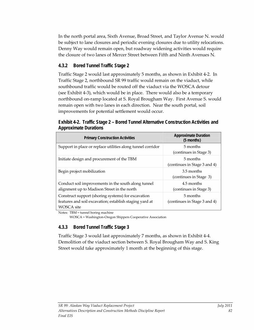
SR 99: Alaskan Way Viaduct Replacement Project July 2011 Alternatives Description and Construction Methods Discipline Report 82 Final EIS
In the north portal area, Sixth Avenue, Broad Street, and Taylor Avenue N. would be subject to lane closures and periodic evening closures due to utility relocations. Denny Way would remain open, but roadway widening activities would require the closure of two lanes of Mercer Street between Fifth and Ninth Avenues N.
4.3.2 Bored Tunnel Traffic Stage 2 Traffic Stage 2 would last approximately 5 months, as shown in Exhibit 4-2. In Traffic Stage 2, northbound SR 99 traffic would remain on the viaduct, while southbound traffic would be routed off the viaduct via the WOSCA detour (see Exhibit 4-3), which would be in place. There would also be a temporary northbound on-ramp located at S. Royal Brougham Way. First Avenue S. would remain open with two lanes in each direction. Near the south portal, soil improvements for potential settlement would occur.
Exhibit 4-2. Traffic Stage 2 – Bored Tunnel Alternative Construction Activities and Approximate Durations
Primary Construction Activities Approximate Duration (5 months)
Support in place or replace utilities along tunnel corridor 5 months (continues in Stage 3)
Initiate design and procurement of the TBM 5 months (continues in Stage 3 and 4)
Begin project mobilization 3.5 months (continues in Stage 3)
Conduct soil improvements in the south along tunnel alignment up to Madison Street in the north
4.5 months (continues in Stage 3)
Construct support (shoring systems) for excavation features and soil excavation; establish staging yard at WOSCA site
5 months (continues in Stage 3 and 4)
Notes: TBM = tunnel boring machine WOSCA = Washington-Oregon Shippers Cooperative Association
4.3.3 Bored Tunnel Traffic Stage 3 Traffic Stage 3 would last approximately 7 months, as shown in Exhibit 4-4. Demolition of the viaduct section between S. Royal Brougham Way and S. King Street would take approximately 1 month at the beginning of this stage.

II
II
II
II
II
II
II
II
II
II
II
II
II
II
II
II
II
II
II
II
II
II
II
II
II
II
II
II
II
II
II
II
II
II
II
II
II
II
II
II
II
II
II
II
II
II
II
II
II
II
II
II
II
II
II
II
II
II
II
II
II
II
II
II
II
II
II
II
II
II
II
II
II
II
II
II
II
II
II
II
II
II
II
II
II
II
II
II
II
II
II
II
II
II
II
II
II
II
II
II
II
II
II
II
II
II
II
II
II
II
II
II
II
II
II
II
II
II
II
II
II
II
II
II
II
II
II
II
II
II
II
II
II
II
II
II
II
II
II
II
II
II
II
II
II
II
II
II
II
II
II
II
II
II
II
II
II
II
II
S F
RO
NT
AG
E R
OA
D

SR 99: Alaskan Way Viaduct Replacement Project July 2011 Alternatives Description and Construction Methods Discipline Report 84 Final EIS
Exhibit 4-4. Traffic Stage 3 – Bored Tunnel Alternative Construction Activities and Approximate Durations
Primary Construction Activities Approximate Duration (7 months)
Support in place or replace utilities along tunnel corridor 7 months Initiate design and procurement of the TBM 7 months
(continues in Stage 4) Begin project mobilization 3.5 months Conduct soil improvements in the south along tunnel alignment up to Madison Street in the north
3.5 months
Construct support (shoring systems) for excavation features and soil excavation; establish staging yard at WOSCA site
7 months
Demolish viaduct between S. Royal Brougham Way and S. King Street 1
1 month
North end: Construct support walls for north portal and TBM retrieval pit
5 months (continues in Stage 4)
Notes: TBM = tunnel boring machine WOSCA = Washington-Oregon Shippers Cooperative Association 1. This activity is part of the S. Holgate Street to S. King Street Viaduct Replacement Project.
In the south end, the S. Holgate Street to S. King Street Viaduct Replacement Project would demolish a section of the viaduct from just north of S. Royal Brougham Way, to S. King Street, which would require the closure of SR 99 to all traffic for 1 week. Once this demolition is completed, both northbound and southbound SR 99 traffic would travel on the WOSCA detour at about S. Royal Brougham Way and connect back to SR 99 using the existing ramp along Railroad Way S. The northbound on-ramp and southbound off-ramp would remain on the temporary ramps. First Avenue S. would still convey two lanes of traffic in each direction between S. King Street and S. Royal Brougham Way.
In the north end, Sixth Avenue N. would remain closed from Thomas Street to Broad Street. Harrison Street would also be closed from Sixth Avenue N. to SR 99. The eastbound lanes of Broad Street and the two right lanes of Mercer Street would remain closed for road-widening activities. Toward the end of Traffic Stage 3, the SR 99 lanes would be shifted to the west as the construction of the Mercer Street overcrossing continues.
4.3.4 Bored Tunnel Traffic Stage 4 Traffic Stage 4 would last approximately 3 to 4 months, as shown in Exhibit 4-5. In the south end, both northbound and southbound SR 99 traffic would use the WOSCA detour and the temporary northbound and southbound ramps. First Avenue S. would continue to convey two lanes of traffic in each direction.

SR 99: Alaskan Way Viaduct Replacement Project July 2011 Alternatives Description and Construction Methods Discipline Report 85 Final EIS
Exhibit 4-5. Traffic Stage 4 – Bored Tunnel Alternative Construction Activities and Approximate Durations
Primary Construction Activities Approximate Duration (3 months)
Initiate design and procurement of the TBM 3 months Construct support (shoring systems) for excavation features and soil excavation; establish staging yard at WOSCA site
3 months
South portal: Construct cut-and-cover tunnel segment from S. Dearborn to S. King Streets
2 months (continues in Stage 5)
North end: Construct support walls for north portal and TBM retrieval pit
3 months
North end: Construct cut-and-cover tunnel segment and tunnel operations building
1 month (continues in Stages
5, 6, and 7) Construct Mercer Street overcrossing and widen Mercer Street from Fifth to Ninth Avenues N.
10 months (continues in Stages 5
and 6) Note: TBM = tunnel boring machine
In the north end, Sixth Avenue N. would remain closed from Thomas Street to Broad Street. Harrison Street would be closed from Sixth Avenue N. to SR 99. The westbound lanes of Broad Street would be closed, and Mercer Street would have two lanes open in each direction as part of the widening activities performed by the City. During Traffic Stage 4, the SR 99 lanes would remain shifted to the west as the construction of the Mercer Street overcrossing continues.
4.3.5 Bored Tunnel Traffic Stage 5 Traffic Stage 5 would last approximately 16 months, as shown in Exhibit 4-6. In the south end, northbound and southbound SR 99 traffic would continue to travel on the WOSCA detour. First Avenue S. would continue to convey two lanes of traffic in each direction.
In the north end, Sixth Avenue N. would remain closed from Thomas Street to Broad Street. Harrison Street would be closed from Sixth Avenue N. to SR 99. Approximately 3 months into Traffic Stage 5, Broad Street would be closed permanently, and Mercer Street would convey two lanes of traffic in each direction. The SR 99 southbound lanes would undergo temporary lane closures to shift the SR 99 lanes from the existing WOSCA detour to the revised WOSCA detour with the divergent northbound and southbound lanes.

SR 99: Alaskan Way Viaduct Replacement Project July 2011 Alternatives Description and Construction Methods Discipline Report 86 Final EIS
Exhibit 4-6. Traffic Stage 5 – Bored Tunnel Alternative Construction Activities and Approximate Durations
Primary Construction Activities Approximate Duration (16 months)
Assemble TBM 3 months Bored tunnel: Drive TBM 13 months Bored tunnel: Install interior tunnel structures and systems
8 months (continues in Stages 6 and 7)
South end: Construct tunnel operations building 13 months (continues in Stages 6 and 7)
South portal: Construct cut-and-cover tunnel segment from S. Dearborn to S. King Streets
2 months
Construct revised WOSCA detour (southbound) 1 month Construct Mercer Street overcrossing and widen Mercer Street from Fifth to Ninth Avenues N.
12 months (continues in Stage 6)
North portal: Construct tunnel operations building 16 months (continues in Stages 6 and 7)
North portal: Construct Harrison/Aurora ramps 7 months (continues in Stage 6)
North portal: Construct cut-and-cover tunnel segment 1 month (continues in Stages 6 and 7)
North portal: Close Broad Street Permanent condition (end of Stage 5)
Note: TBM = tunnel boring machine
4.3.6 Bored Tunnel Traffic Stage 6 Traffic Stage 6 would last approximately 9 months, as shown in Exhibit 4-7. In the south end, northbound and southbound SR 99 traffic would travel on the revised WOSCA detour (see Exhibit 4-8). First Avenue S. would continue to convey two lanes of traffic in each direction.
The southbound SR 99 lanes would be shifted onto the west half of the Harrison/Aurora ramps. Later in this traffic stage, after the traffic has been shifted over to use the west half, the east half of the Harrison/Aurora ramps would be built. Sixth Avenue N. would remain closed from Thomas Street to Broad Street. Harrison Street would also be closed from Sixth Avenue N. to SR 99. Mercer Street would be opened to three lanes in each direction from Fifth Avenue N. to I-5.

SR 99: Alaskan Way Viaduct Replacement Project July 2011 Alternatives Description and Construction Methods Discipline Report 87 Final EIS
Exhibit 4-7. Traffic Stage 6 – Bored Tunnel Alternative Construction Activities and Approximate Durations
Primary Construction Activities Approximate Duration (9 months)
Bored tunnel: Drive TBM First 4 months Bored tunnel: Install interior tunnel structures and systems
9 months (continues in Stage 7)
South portal: Construct tunnel operations building 9 months (continues in Stage 7)
South portal: Construct cut-and-cover tunnel and retained cut connection
9 months (continues in Stage 7)
North portal: Construct tunnel operations building 9 months (continues in Stage 7)
North portal: Construct cut-and-cover tunnel segment 9 months (continues in Stage 7)
North portal: Construct shoring, excavate, and build Harrison Street ramp structures
6 months
North portal: Construct Harrison/Aurora ramps 3 months Construct Mercer Street overcrossing and widen Mercer Street from Fifth to Ninth Avenues N.
12 months
North portal: Construct southbound and northbound SR 99 from tunnel portal at Harrison Street to meet existing grade
1 month (continues in Stage 7)
Retrieve TBM 6 months Notes: SR = State Route
TBM = tunnel boring machine

II
II
II
II
II
II
II
II
II
II
II
II
II
II
II
II
II
II
II
II
II
II
II
II
II
II
II
II
II
II
II
II
II
II
II
II
II
II
II
II
II
II
II
II
II
II
II
II
II
II
II
II
II
II
II
II
II
II
II
II
II
II
II
II
II
II
II
II
II
II
II
II
II
II
II
II
II
II
II
II
II
II
II
II
II
II
II
II
II
II
II
II
II
II
II
II
II
II
II
II
II
II
II
II
II
II
II
II
II
II
II
II
II
II
II
II
II
II
II
II
II
II
II
II
II
II
II
II
II
II
II
II
II
II
II
II
II
II
II
II
II
II
II
II
II
II
II
II
II
II
II
II
II
II
II
II
II
II
II
FIR
ST
AV
EN
UE
S
OC
CID
EN
TA
L A
VE
NU
E S
CO
LO
RA
DO
AV
EN
UE
S
RA
I LR
OA
D W
AY
S
AL
AS
KA
N W
AY
S
S R O Y A L B R O U G H A M W A Y
S A T L A N T I C S T R E E T / S R 5 1 9
S K I N G S T R E E T
S F
RO
NT
AG
E R
OA
D
TERMINAL 46
QWEST FIELD
SAFECO FIELD
STAGING/WORK AREA
Railroad Overcrossing
ContractorRoad
SR 99 Southboundrestricted to 2 lanes
SR 99 Northboundrestricted to 2 lanes
Northbound On
Southbound Off
Staging/Work Areas
Northbound SR 99
Southbound SR 99
Contractor Road
0 20 40
SCALE IN FEET
Exhibit 4-8
Revised WOSCA Detour

SR 99: Alaskan Way Viaduct Replacement Project July 2011 Alternatives Description and Construction Methods Discipline Report 89 Final EIS
4.3.7 Bored Tunnel Traffic Stage 7 Traffic Stage 7 would last approximately 8 months, as shown in Exhibit 4-9. In the south end, the northbound and southbound traffic would continue via a temporary southbound off-ramp near S. Atlantic Street to the revised WOSCA detour (see Exhibit 4-8), which would be in place. There would also be a temporary northbound on-ramp located at S. Royal Brougham Way. First Avenue S. would continue to convey two lanes of traffic in each direction.
Sixth Avenue N. would remain closed from Thomas Street to Broad Street, and Harrison Street would remain closed from Sixth Avenue N. to SR 99.
At the end of Stage 7, there would be up to a 3-week closure to connect SR 99 to the bored tunnel.
Exhibit 4-9. Traffic Stage 7 – Bored Tunnel Alternative Construction Activities and Approximate Durations
Primary Construction Activities Approximate Duration 8 months)
Bored tunnel: Install interior tunnel structures and systems 6 months Bored tunnel: Commission interior systems 6 months South portal: Construct tunnel operations building 6 months South portal: Construct cut-and-cover tunnel and retained cut connection
3 months
North portal: Construct tunnel operations building 3 months North portal: Construct both southbound and northbound SR 99 from tunnel portal at Harrison Street to meet existing grade
2 months
North portal: Construct shoring for northbound SR 99; excavate and build northbound SR 99
2 months
North portal: Construct cut-and-cover tunnel segment 2 months
North portal: Construct Republican Street and Sixth Avenue N. ramp structures
8 months
Connect SR 99 to the bored tunnel Several weeks Note: SR = State Route
4.3.8 Bored Tunnel Traffic Stage 8 Traffic Stage 8 would last approximately 12 months, as shown in Exhibit 4-10. When this stage starts, SR 99 traffic would begin using the newly constructed bored tunnel. In the south end, Alaskan Way would be reduced in width between S. King Street and Pike Street to allow for the demolition and removal of the viaduct structure. Drivers on First Avenue S. would experience lane closures necessary for street restoration. Between Railroad Way S. and S. Royal Brougham Way, traffic would be reduced to

SR 99: Alaskan Way Viaduct Replacement Project July 2011 Alternatives Description and Construction Methods Discipline Report 90 Final EIS
one lane in each direction. Various streets between S. King Street and Battery Street would experience periodic street closures to facilitate the viaduct demolition.
In the north end, Denny Way, Harrison Street, Sixth Avenue N., Taylor Avenue N., and Broad Street lanes would be restricted to support utility relocation and surface street restoration activities. The reconstruction of Aurora Avenue between Harrison Street and Denny Way would include filling the currently depressed Aurora Avenue roadway to grade at the north portal of the Battery Street Tunnel, and the existing Denny Way ramps would be closed. Traffic would use the new intersection and on- and off-ramps to and from SR 99 at the intersection of Harrison Street.
Exhibit 4-10. Traffic Stage 8 – Bored Tunnel Alternative Construction Activities and Approximate Durations
Primary Construction Activities Approximate Duration (12 months)
Demolish and remove existing viaduct 9 months
Decommission Battery Street Tunnel 9 months
South portal area: Remove WOSCA detour 1 month
South portal area: Restore surface streets 12 months
North portal area: Restore surface streets 12 months Note: WOSCA = Washington-Oregon Shippers Cooperative Association
4.4 Cut-and-Cover Tunnel Alternative Construction Stages and Durations For the Cut-and-Cover Tunnel Alternative, the construction sequencing and the total project duration is expected to take 8.75 years. The only improvements that could be deferred are the replacement of the north waterfront seawall, the increased vertical clearance in the Battery Street Tunnel, and the improvements to Aurora Avenue. The most intensive traffic stage for construction of the Cut-and-Cover Tunnel Alternative would be Traffic Stage 3, when SR 99 and the Alaskan Way surface street would be closed. However, east-west access to the central waterfront businesses would be maintained during this stage.
Some construction related to the S. Holgate Street to S. King Street Viaduct Replacement Project would overlap with construction of the Cut-and-Cover Tunnel Alternative. The construction associated with the S. Holgate Street to S. King Street Viaduct Replacement Project, which began construction in mid-2010, will continue through mid-2014. Construction activities associated with the Cut-and-Cover Tunnel Alternative would continue for approximately 5 years after the completion of the S. Holgate Street to S. King Street Viaduct Replacement Project. Aside from the disruptions associated with the S. Holgate Street to S. King Street Viaduct Replacement Project, traffic in the area around the WOSCA detour (First Avenue S.

SR 99: Alaskan Way Viaduct Replacement Project July 2011 Alternatives Description and Construction Methods Discipline Report 91 Final EIS
and Alaskan Way) would be affected when the Alaskan Way Viaduct is closed for the construction of the cut-and-cover tunnel.
In terms of pedestrian movements, the Cut-and-Cover Tunnel Alternative assumes that both south and north pedestrian connections along First Avenue S. between S. Royal Brougham Way and S. King Street would be maintained to the maximum extent possible. There may be short periods during key construction activities when some of the connections may be detoured.
The assumption used for the sequencing the construction activities associated with the Cut-and-Cover Tunnel Alternative is that Alaskan Way would be closed to traffic (north-south) during Traffic Stages 2 to 4 (51 months); however, east-west access would be maintained for waterfront businesses.
4.4.1 Cut-and-Cover Tunnel Traffic Stage 1 Traffic Stage 1 would last approximately 30 months, as shown in Exhibit 4-11. Construction activities in Traffic Stage 1 would consist primarily of the relocation of existing public and private utilities and other construction activities that would not interfere with utility relocation. Even though Traffic Stage 1 focuses primarily on utility relocation, these activities would continue in all construction stages. The Traffic Stage 1 activities could be performed before the beginning of the tunnel construction, including the seawall construction. Roadway restrictions and closures during Traffic Stage 1 are described below:
• Northbound and southbound SR 99. Traffic on SR 99 would begin using the WOSCA detour configuration midway through Traffic Stage 1. The configuration of the WOSCA detour is shown in Exhibit 4-3.
• Alaskan Way. Parking under the existing viaduct would be removed. The Alaskan Way surface street would be reduced to one lane in each direction and would be diverted around the Traffic Stage 1 construction activities. Existing access to the waterfront would be maintained.
• Aurora Avenue. SR 99 traffic would be maintained in the existing configuration.
4.4.2 Cut-and-Cover Tunnel Traffic Stage 2 Traffic Stage 2 would last approximately 9 months, as shown in Exhibit 4-12. In Traffic Stage 2, the initial relocation of utilities would be completed and construction of the new SR 99 would begin while traffic is maintained on the existing SR 99. This would require closure of the existing Western off-ramp and reconfiguring SR 99 such that northbound traffic will use part of the off-ramp during this stage of construction. Traffic Stage 2 construction activities can be performed before the existing viaduct is closed.

SR 99: Alaskan Way Viaduct Replacement Project July 2011 Alternatives Description and Construction Methods Discipline Report 92 Final EIS
Exhibit 4-11. Traffic Stage 1 – Cut-and-Cover Tunnel Alternative Construction Activities and Approximate Durations
Primary Construction Activities Approximate Duration (30 months)
Relocate, support, or replace public and private utilities along cut-and-cover tunnel corridor (to temporary or to permanent locations)
30 months (continues in Stages 2, 3, 4, and 5)
Construct or improve secant pile tunnel/seawall in Colman Curve section (S. King Street to Pike Street)
9 months (continues in Stage 2)
Construct temporary over-water bridge from Pier 48 to Colman Dock
6 months
Construct temporary pedestrian walkways between Piers 54 and 55 and between Piers 56 and 57
6 months
Establish construction staging areas 3 months
Exhibit 4-12. Traffic Stage 2 – Cut-and-Cover Tunnel Alternative Construction Activities and Approximate Durations
Primary Construction Activities Approximate Duration (9 months)
Relocate, support or replace public and private utilities along cut-and-cover tunnel corridor (to temporary or to permanent locations)
30 months (continues in Stages 3, 4,
and 5) Construct or improve secant pile tunnel wall/seawall in Colman Curve section (S. King Street to Pike Street)
9 months
Build stacked cut-and-cover tunnel (S. Jackson Street to Seneca Street)
9 months (continues in Stage 3)
Construct BNSF Railway retaining wall (Pike Street to Battery Street Tunnel)
9 months
Start Aurora Avenue improvements – relocate utilities and temporary bridges
9 months
The roadway restrictions and closures during Traffic Stage 2 are described below:
• Northbound SR 99. SR 99 would remain open in the existing configuration. The WOSCA detour on-ramp, the Seneca Street off-ramp, and the Western Avenue off-ramp would remain open.
• Southbound SR 99. SR 99 would remain open in the existing configuration. The temporary southbound off-ramp near S. Atlantic Street, the Columbia Street on-ramp, and the Elliott Avenue on-ramp would remain open.

SR 99: Alaskan Way Viaduct Replacement Project July 2011 Alternatives Description and Construction Methods Discipline Report 93 Final EIS
• Alaskan Way. The north-south through lanes on the Alaskan Way surface street would be closed between S. Atlantic and Pine Streets. Transverse (east-west) access across the corridor to the waterfront would be provided for deliveries and emergency vehicles. Limited public parking would be available within the corridor.
• Aurora Avenue. SR 99 traffic would be maintained in the existing configuration, except for nighttime closures as needed for construction of the temporary bridges, particularly for the erection of beams.
4.4.3 Cut-and-Cover Tunnel Traffic Stage 3 Traffic Stage 3 would last approximately 15 months, as shown in Exhibit 4-13. In Traffic Stage 3, the SR 99 corridor would be closed to north-south traffic, and the majority of the construction activities could be constructed concurrently. The northbound lanes on the existing viaduct would remain. Northbound traffic would then detour onto the temporary Bell Street overcrossing structure, into the Battery Street Tunnel, and onto SR 99. Construction during Stage 3 would include the removal of the viaduct structure and the start of construction of the stacked tunnel transitions and the Battery Street Tunnel improvements. After these activities, SR 99 from S. Spokane Street to Denny Way could be completed.
Exhibit 4-13. Traffic Stage 3 – Cut-and-Cover Tunnel Alternative Construction Activities and Approximate Durations
Primary Construction Activities Approximate Duration (15 months)
Relocate, support or replace public and private utilities along cut-and-cover tunnel corridor (to temporary or to permanent locations)
30 months (continues in Stages 4 and 5)
Complete stacked cut-and-cover tunnel (S. Jackson Street to Seneca Street)
15 months
Remove existing viaduct (Pike Street to Battery Street Tunnel – southbound)
6 months
Construct partial lowered Aurora Avenue (west half) (southbound lanes)
6 months (continues in Stage 4)
Construct temporary bridges at John Street and Thomas Street
9 months
Construct southbound cut-and-cover tunnel under Elliott/Western Avenues (Lenora Street to Battery Street Tunnel)
12 months (continues in Stage 4)
Construct northbound cut-and-cover tunnel under Elliott/Western Avenues (Lenora Street to Battery Street Tunnel)
12 months (continues in Stage 4)
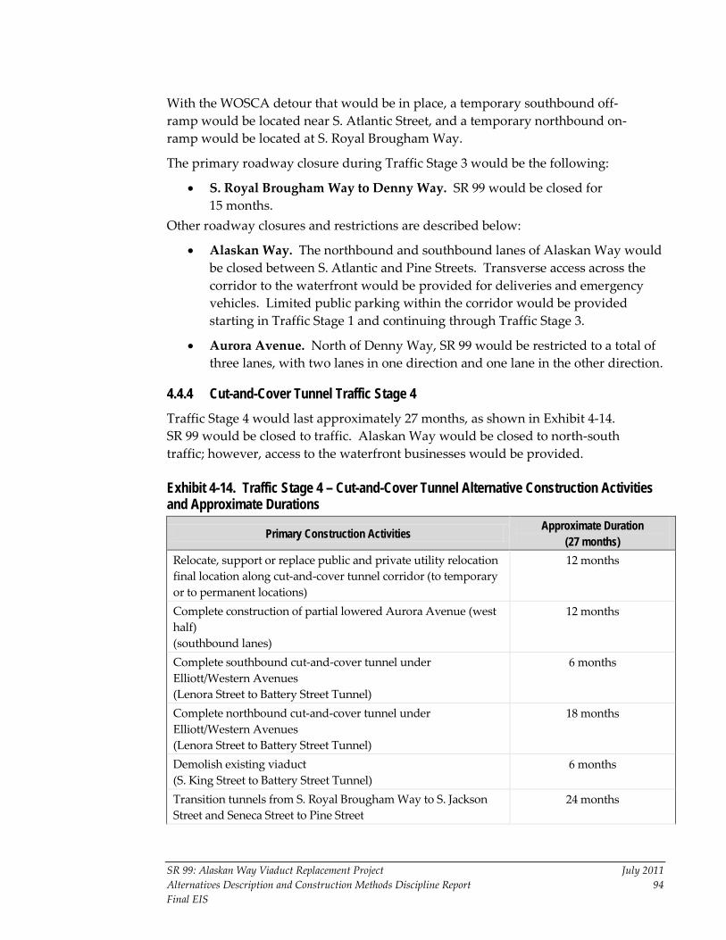
SR 99: Alaskan Way Viaduct Replacement Project July 2011 Alternatives Description and Construction Methods Discipline Report 94 Final EIS
With the WOSCA detour that would be in place, a temporary southbound off-ramp would be located near S. Atlantic Street, and a temporary northbound on-ramp would be located at S. Royal Brougham Way.
The primary roadway closure during Traffic Stage 3 would be the following:
• S. Royal Brougham Way to Denny Way. SR 99 would be closed for 15 months.
Other roadway closures and restrictions are described below:
• Alaskan Way. The northbound and southbound lanes of Alaskan Way would be closed between S. Atlantic and Pine Streets. Transverse access across the corridor to the waterfront would be provided for deliveries and emergency vehicles. Limited public parking within the corridor would be provided starting in Traffic Stage 1 and continuing through Traffic Stage 3.
• Aurora Avenue. North of Denny Way, SR 99 would be restricted to a total of three lanes, with two lanes in one direction and one lane in the other direction.
4.4.4 Cut-and-Cover Tunnel Traffic Stage 4 Traffic Stage 4 would last approximately 27 months, as shown in Exhibit 4-14. SR 99 would be closed to traffic. Alaskan Way would be closed to north-south traffic; however, access to the waterfront businesses would be provided.
Exhibit 4-14. Traffic Stage 4 – Cut-and-Cover Tunnel Alternative Construction Activities and Approximate Durations
Primary Construction Activities Approximate Duration (27 months)
Relocate, support or replace public and private utility relocation final location along cut-and-cover tunnel corridor (to temporary or to permanent locations)
12 months
Complete construction of partial lowered Aurora Avenue (west half) (southbound lanes)
12 months
Complete southbound cut-and-cover tunnel under Elliott/Western Avenues (Lenora Street to Battery Street Tunnel)
6 months
Complete northbound cut-and-cover tunnel under Elliott/Western Avenues (Lenora Street to Battery Street Tunnel)
18 months
Demolish existing viaduct (S. King Street to Battery Street Tunnel)
6 months
Transition tunnels from S. Royal Brougham Way to S. Jackson Street and Seneca Street to Pine Street
24 months

Exhibit 4-14. Traffic Stage 4 – Cut-and-Cover Tunnel Alternative Construction Activities and Approximate Durations (continued)
SR 99: Alaskan Way Viaduct Replacement Project July 2011 Alternatives Description and Construction Methods Discipline Report 95 Final EIS
Primary Construction Activities Approximate Duration (27 months)
Lower inverts for both northbound and southbound Battery Street Tunnel portals to increase vertical clearance
12 months
Build ventilation building and install systems 27 months Build vent buildings and systems for Battery Street Tunnel and install finishes; widen south portal of Battery Street Tunnel and match to lower profile
21 months
Construct lowered Aurora (east half) (northbound lanes)
12 months
Construct southbound aerial structure over BNSF Railway (Pike Street to Battery Street Tunnel)
18 months
Construct northbound aerial structure over BNSF Railway (Pike Street to Battery Street Tunnel)
12 months (continues in Stage 5)
Rebuild seawall (Pike Street to Broad Street)
3 months (continues in Stages 5 and 6)
Begin construction of Thomas and Harrison Street overpasses 9 months (continues in Stage 5)
4.4.5 Cut-and-Cover Tunnel Traffic Stage 5 Traffic Stage 5 would last approximately 12 months, as shown in Exhibit 4-15. Southbound SR 99 would be in operation from the Battery Street Tunnel south. Northbound SR 99 would be closed to traffic for 12 months.
Exhibit 4-15. Traffic Stage 5 – Cut-and-Cover Tunnel Alternative Construction Activities and Approximate Durations
Primary Construction Activities Approximate Duration (12 months)
Final utility relocations (S. King Street to Battery Street Tunnel)
12 months
Construct northbound aerial structure over BNSF Railway (Pike Street to Battery Street Tunnel)
6 months
Rebuild seawall (Pike Street to Broad Street)
12 months (continues in Stage 6)
Complete Thomas Street and Harrison Street overpasses 3 months Complete northbound tunnel system and finishes 12 months Improve surface streets in the north end 12 months
Surface street operations would include one-lane operations in each direction for both northbound and southbound travel west of the Alaskan Way corridor. Broad Street would be closed.

SR 99: Alaskan Way Viaduct Replacement Project July 2011 Alternatives Description and Construction Methods Discipline Report 96 Final EIS
4.4.6 Cut-and-Cover Tunnel Traffic Stage 6 Traffic Stage 6 would last approximately 12 months, as shown in Exhibit 4-16. Northbound and southbound SR 99 would operate on the final configuration.
Exhibit 4-16. Traffic Stage 6 – Cut-and-Cover Tunnel Alternative Construction Activities and Approximate Durations
Primary Construction Activities Approximate Duration (12 months)
Rebuild seawall (Pike Street to Broad Street)
3 months
Conduct project closeout and restore surface streets 12 months
4.5 Elevated Structure Alternative Construction Stages and Durations For the Elevated Structure Alternative, the construction sequencing and the total project duration is expected to take 10 years.
The traffic approach for the Elevated Structure Alternative was developed to accommodate two lanes of traffic in each direction at all times, except for a 2- to 4-month total closure period in Traffic Stage 4 and a 3-month total closure period in Traffic Stage 7. Two designated traffic detours would be used to maintain two lanes of traffic in the corridor throughout the construction period.
Some construction related to the S. Holgate Street to S. King Street Viaduct Replacement Project would overlap with the construction associated with the Elevated Structure Alternative. The S. Holgate Street to S. King Street Viaduct Replacement Project, which began construction in mid-2010, will continue through mid-2014.
For pedestrian movements, the Elevated Structure Alternative assumes that both south and north pedestrian connections along First Avenue S. between S. Royal Brougham Way and S. King Street would be maintained to the maximum extent possible. There may be short periods during key construction activities when some of the connections may be detoured.
The assumptions used for the sequencing of the construction activities associated with the Elevated Structure Alternative are the following:
• SR 99 will convey two lanes in each direction throughout construction, except for a 2- to 4-month total closure in Traffic Stage 4 and a 3-month total closure in Traffic Stage 7. The Broad Street detour and the WOSCA detour will be used to help keep traffic flowing on SR 99, starting in Traffic Stage 1. The configuration of the WOSCA detour is shown in Exhibit 4-3.
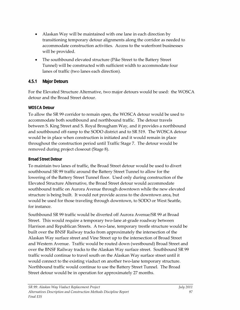
SR 99: Alaskan Way Viaduct Replacement Project July 2011 Alternatives Description and Construction Methods Discipline Report 97 Final EIS
• Alaskan Way will be maintained with one lane in each direction by transitioning temporary detour alignments along the corridor as needed to accommodate construction activities. Access to the waterfront businesses will be provided.
• The southbound elevated structure (Pike Street to the Battery Street Tunnel) will be constructed with sufficient width to accommodate four lanes of traffic (two lanes each direction).
4.5.1 Major Detours
For the Elevated Structure Alternative, two major detours would be used: the WOSCA detour and the Broad Street detour.
WOSCA Detour To allow the SR 99 corridor to remain open, the WOSCA detour would be used to accommodate both southbound and northbound traffic. The detour travels between S. King Street and S. Royal Brougham Way, and it provides a northbound and southbound off-ramp to the SODO district and to SR 519. The WOSCA detour would be in place when construction is initiated and it would remain in place throughout the construction period until Traffic Stage 7. The detour would be removed during project closeout (Stage 8).
Broad Street Detour To maintain two lanes of traffic, the Broad Street detour would be used to divert southbound SR 99 traffic around the Battery Street Tunnel to allow for the lowering of the Battery Street Tunnel floor. Used only during construction of the Elevated Structure Alternative, the Broad Street detour would accommodate southbound traffic on Aurora Avenue through downtown while the new elevated structure is being built. It would not provide access to the downtown area, but would be used for those traveling through downtown, to SODO or West Seattle, for instance.
Southbound SR 99 traffic would be diverted off Aurora Avenue/SR 99 at Broad Street. This would require a temporary two-lane at-grade roadway between Harrison and Republican Streets. A two-lane, temporary trestle structure would be built over the BNSF Railway tracks from approximately the intersection of the Alaskan Way surface street and Vine Street up to the intersection of Broad Street and Western Avenue. Traffic would be routed down (westbound) Broad Street and over the BNSF Railway tracks to the Alaskan Way surface street. Southbound SR 99 traffic would continue to travel south on the Alaskan Way surface street until it would connect to the existing viaduct on another two-lane temporary structure. Northbound traffic would continue to use the Battery Street Tunnel. The Broad Street detour would be in operation for approximately 27 months.

SR 99: Alaskan Way Viaduct Replacement Project July 2011 Alternatives Description and Construction Methods Discipline Report 98 Final EIS
4.5.2 Elevated Structure Traffic Stage 1 Traffic Stage 1 would last approximately 30 months, as shown in Exhibit 4-17. The primary construction activities in Traffic Stage 1 would be the relocation of existing public and private utilities and other construction activities that would not interfere with the utility relocation. Even though Traffic Stage 1 would focus mostly on utility relocation, these activities would continue during all construction stages. Traffic Stage 1 activities could be performed before the beginning of the major construction activities that would follow in Traffic Stages 2, 3, 4, and 5.
Exhibit 4-17. Traffic Stage 1 – Elevated Structure Alternative Construction Activities and Approximate Durations
Primary Construction Activities Approximate Duration (30 months)
Remove parking under existing viaduct and remove waterfront streetcar tracks
3 months
Relocate utilities 30 months Construct seawall (S. King Street to Pike Street)
9 months (continues in Stages 2 and 3)
Construct temporary pedestrian walkways between Piers 54 and 55 and Piers 56 and 57
9 months
Construct temporary over-water bridge from Pier 48 to Colman Dock
9 months
The roadway closures and restrictions during Traffic Stage 1 include the following:
• Northbound and southbound SR 99. SR 99 would remain open in the existing configuration.
• Alaskan Way. Parking under the existing viaduct would be removed. The Alaskan Way surface street would be reduced to one lane in each direction, and traffic would be diverted around the Traffic Stage 1 construction activities. Existing access to the waterfront would be maintained.
• Aurora Avenue. SR 99 traffic would be maintained in the existing configuration.
4.5.3 Elevated Structure Traffic Stage 2 Traffic Stage 2 would last approximately 9 months, as shown in Exhibit 4-18. During Traffic Stage 2, SR 99 would be reduced to two lanes in each direction, with night and weekend closures. SR 99 traffic would remain on the existing
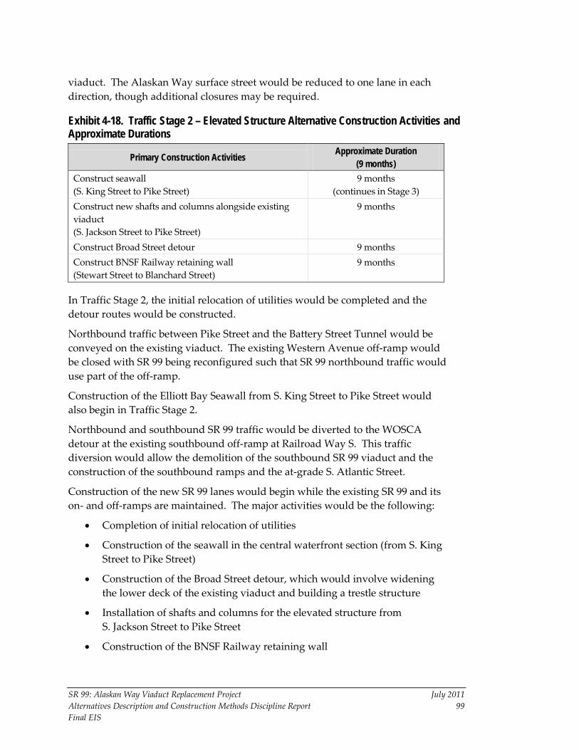
SR 99: Alaskan Way Viaduct Replacement Project July 2011 Alternatives Description and Construction Methods Discipline Report 99 Final EIS
viaduct. The Alaskan Way surface street would be reduced to one lane in each direction, though additional closures may be required.
Exhibit 4-18. Traffic Stage 2 – Elevated Structure Alternative Construction Activities and Approximate Durations
Primary Construction Activities Approximate Duration (9 months)
Construct seawall (S. King Street to Pike Street)
9 months (continues in Stage 3)
Construct new shafts and columns alongside existing viaduct (S. Jackson Street to Pike Street)
9 months
Construct Broad Street detour 9 months Construct BNSF Railway retaining wall (Stewart Street to Blanchard Street)
9 months
In Traffic Stage 2, the initial relocation of utilities would be completed and the detour routes would be constructed.
Northbound traffic between Pike Street and the Battery Street Tunnel would be conveyed on the existing viaduct. The existing Western Avenue off-ramp would be closed with SR 99 being reconfigured such that SR 99 northbound traffic would use part of the off-ramp.
Construction of the Elliott Bay Seawall from S. King Street to Pike Street would also begin in Traffic Stage 2.
Northbound and southbound SR 99 traffic would be diverted to the WOSCA detour at the existing southbound off-ramp at Railroad Way S. This traffic diversion would allow the demolition of the southbound SR 99 viaduct and the construction of the southbound ramps and the at-grade S. Atlantic Street.
Construction of the new SR 99 lanes would begin while the existing SR 99 and its on- and off-ramps are maintained. The major activities would be the following:
• Completion of initial relocation of utilities
• Construction of the seawall in the central waterfront section (from S. King Street to Pike Street)
• Construction of the Broad Street detour, which would involve widening the lower deck of the existing viaduct and building a trestle structure
• Installation of shafts and columns for the elevated structure from S. Jackson Street to Pike Street
• Construction of the BNSF Railway retaining wall

SR 99: Alaskan Way Viaduct Replacement Project July 2011 Alternatives Description and Construction Methods Discipline Report 100 Final EIS
• Relocation of utilities for the Aurora Avenue improvements
• Construction of temporary bridges over Aurora Avenue at Thomas and John Streets
The following roadway closures and restrictions during Traffic Stage 2 would allow both northbound and southbound SR 99 to remain on the existing viaduct:
• Alaskan Way. North-south traffic on the Alaskan Way surface street would be open to one lane in each direction between S. Massachusetts and Pine Streets. The one lane in each direction would be provided by moving the detour alignments along the corridor as needed to accommodate construction activities. Transverse access across the corridor to the waterfront would be provided for deliveries and emergency vehicles. Limited public parking would be available within the corridor.
• Aurora Avenue. SR 99 traffic would be maintained in the existing configuration.
4.5.4 Elevated Structure Traffic Stage 3 Traffic Stage 3 would last approximately 27 months, as shown in Exhibit 4-19.
Exhibit 4-19. Traffic Stage 3 – Elevated Structure Alternative Construction Activities and Approximate Durations
Primary Construction Activities Approximate Duration (27 months)
Construct seawall (S. King Street to Pike Street)
3 months
Construct new southbound aerial viaduct (Pike Street to Battery Street Tunnel)
24 months
Construct southbound structure for side-by-side southbound transition lanes (S. King Street to S. Jackson Street)
24 months
Widen lower level (southbound) of existing viaduct (S. King Street to Pike Street)
15 months
Aurora Avenue improvements: Construct west half (southbound lanes) of lowered Aurora Avenue
18 months
Aurora Avenue improvements: Construct east half (northbound lanes) of lowered Aurora Avenue
9 months (continues in Stage 4)
Construct Thomas and Harrison Street overpasses 3 months (continues in Stages 4 and 5)
Battery Street Tunnel: Lower inverts for northbound and southbound lanes and retrofit existing walls
24 months
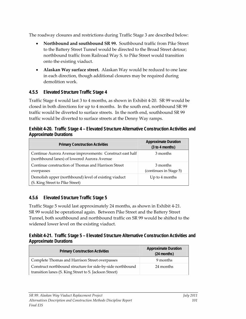
SR 99: Alaskan Way Viaduct Replacement Project July 2011 Alternatives Description and Construction Methods Discipline Report 101 Final EIS
The roadway closures and restrictions during Traffic Stage 3 are described below:
• Northbound and southbound SR 99. Southbound traffic from Pike Street to the Battery Street Tunnel would be directed to the Broad Street detour; northbound traffic from Railroad Way S. to Pike Street would transition onto the existing viaduct.
• Alaskan Way surface street. Alaskan Way would be reduced to one lane in each direction, though additional closures may be required during demolition work.
4.5.5 Elevated Structure Traffic Stage 4 Traffic Stage 4 would last 3 to 4 months, as shown in Exhibit 4-20. SR 99 would be closed in both directions for up to 4 months. In the south end, northbound SR 99 traffic would be diverted to surface streets. In the north end, southbound SR 99 traffic would be diverted to surface streets at the Denny Way ramps.
Exhibit 4-20. Traffic Stage 4 – Elevated Structure Alternative Construction Activities and Approximate Durations
Primary Construction Activities Approximate Duration (3 to 4 months)
Continue Aurora Avenue improvements: Construct east half (northbound lanes) of lowered Aurora Avenue
3 months
Continue construction of Thomas and Harrison Street overpasses
3 months (continues in Stage 5)
Demolish upper (northbound) level of existing viaduct (S. King Street to Pike Street)
Up to 4 months
4.5.6 Elevated Structure Traffic Stage 5 Traffic Stage 5 would last approximately 24 months, as shown in Exhibit 4-21. SR 99 would be operational again. Between Pike Street and the Battery Street Tunnel, both southbound and northbound traffic on SR 99 would be shifted to the widened lower level on the existing viaduct.
Exhibit 4-21. Traffic Stage 5 – Elevated Structure Alternative Construction Activities and Approximate Durations
Primary Construction Activities Approximate Duration (24 months)
Complete Thomas and Harrison Street overpasses 9 months Construct northbound structure for side-by-side northbound transition lanes (S. King Street to S. Jackson Street)
24 months
Exhibit 4-21. Traffic Stage 5 – Elevated Structure Alternative Construction Activities and Approximate Durations (continued)
SR 99: Alaskan Way Viaduct Replacement Project July 2011 Alternatives Description and Construction Methods Discipline Report 102 Final EIS
Primary Construction Activities Approximate Duration (24 months)
Construct upper (northbound) level of elevated structure (Pike Street to Battery Street Tunnel)
24 months
Construct upper (northbound) level of elevated structure (S. King Street to Pike Street)
18 months
Perform final utility relocations (S. King Street to Battery Street Tunnel)
12 months
4.5.7 Elevated Structure Traffic Stage 6 Traffic Stage 6 would last approximately 21 months, as shown in Exhibit 4-22. Southbound and northbound SR 99 would operate with two lanes on the completed upper level of the elevated structure. Between S. Holgate Street and Pike Street, Alaskan Way would operate with one lane in each direction along the west side of the Alaskan Way corridor.
Exhibit 4-22. Traffic Stage 6 – Elevated Structure Alternative Construction Activities and Approximate Durations
Primary Construction Activities Approximate Duration (21 months)
Demolish lower (southbound) level of existing viaduct (S. King Street to Pike Street)
6 months
Construct lower (southbound) level of elevated structure (S. King Street to Pike Street)
18 months
Remove Broad Street detour 6 months Improve surface streets in the north end 12 months
4.5.8 Elevated Structure Traffic Stage 7 Traffic Stage 7 would last approximately 3 months, as shown in Exhibit 4-23. SR 99 would be closed, and traffic would use the newly configured surface streets.
Exhibit 4-23. Traffic Stage 7 – Elevated Structure Alternative Construction Activities and Approximate Durations
Primary Construction Activities Approximate Duration (3 months)
Remove and replace temporary transition structure to completed S. Holgate Street to S. King Street roadway section
3 months
Conduct project closeout and restore surface streets 3 months (continues in Stage 8)
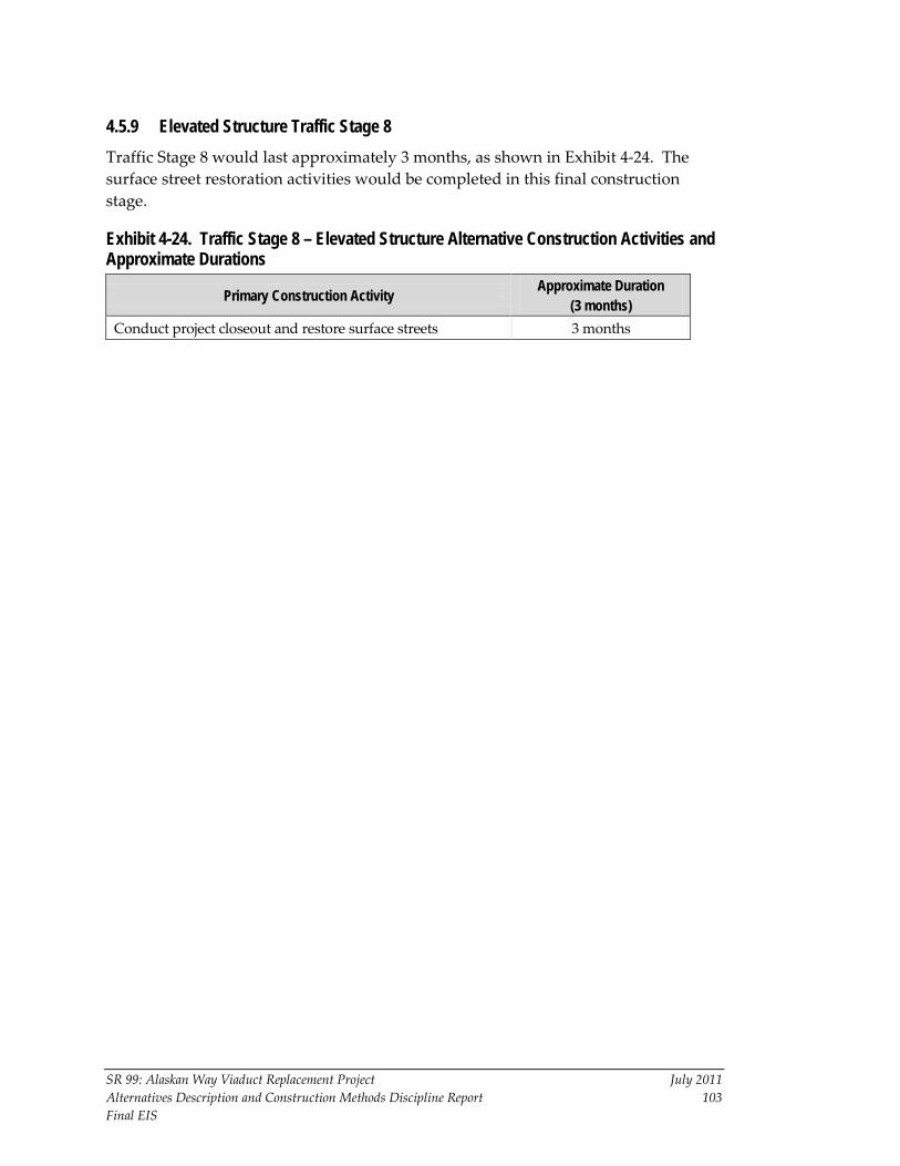
SR 99: Alaskan Way Viaduct Replacement Project July 2011 Alternatives Description and Construction Methods Discipline Report 103 Final EIS
4.5.9 Elevated Structure Traffic Stage 8 Traffic Stage 8 would last approximately 3 months, as shown in Exhibit 4-24. The surface street restoration activities would be completed in this final construction stage.
Exhibit 4-24. Traffic Stage 8 – Elevated Structure Alternative Construction Activities and Approximate Durations
Primary Construction Activity Approximate Duration (3 months)
Conduct project closeout and restore surface streets 3 months

This Page Intentionally Left Blank

SR 99: Alaskan Way Viaduct Replacement Project July 2011 Alternatives Description and Construction Methods Discipline Report 105 Final EIS
Chapter 5 REFERENCES Parsons Brinckerhoff. 2009a. SR 99 Bored Tunnel Alternative – Corridor
Operations Concept. Seattle, Washington. June 2009.
Parsons Brinckerhoff. 2009b. SR 99 Bored Tunnel Alternative – Urban Design Concepts. Seattle, Washington. June 2009.
Parsons Brinckerhoff. 2009c. SR 99 Bored Tunnel Alternative – Utility Impact Report. Seattle, Washington. June 2009.
Parsons Brinckerhoff. 2009d. SR 99 Bored Tunnel Alternative – Final Staging, Sequencing, Constructability, and Construction Impacts Study. Seattle, Washington. July 2009.
Sivalingham, P., and G. Klados. 2006. The Selection of the Working Methods and Tunnel Boring Machines for the SMART Project. Paper presented at the International Conference and Exhibition on Tunneling and Trenchless Technology, 7-9 March 2006, Subang, Selangor, Malaysia. Available at: http://www.ita-aites.org/cms/fileadmin/filemounts/general/pdf/ ItaAssociation/Organisation/Members/MemberNations/Malaysia/S6-11.pdf. Accessed April 2010.
TY Lin. 2005. TY Lin. International Independent Engineering Assessment of the Continuing Impacts of the February 2001 Earthquake Upon the Alaskan Way Viaduct in Seattle, Washington.
WSDOT (Washington State Department of Transportation). 2008. Central and North Seawall Concept Studies. Prepared by Parsons Brinckerhoff. December.
WSDOT, City of Seattle, and U.S. Department of Transportation, Federal Highway Administration. 2004. SR 99: Alaskan Way Viaduct & Seawall Replacement Project Draft Environmental Impact Statement. Washington State Department of Transportation, Urban Corridors Office, Seattle, Washington.
WSDOT, City of Seattle, and U.S. Department of Transportation, Federal Highway Administration. 2006. SR 99: Alaskan Way Viaduct & Seawall Replacement Project Supplemental Draft Environmental Impact Statement and Section 4(f) Evaluation. Washington State Department of Transportation, Urban Corridors Office, Seattle, Washington.
WSDOT, City of Seattle, and U.S. Department of Transportation, Federal Highway Administration. 2010. SR 99: Alaskan Way Viaduct Replacement Project Supplemental Draft Environmental Impact Statement and Section 4(f) Evaluation. Washington State Department of Transportation, Urban Corridors Office, Seattle, Washington.

This Page Intentionally Left Blank