albany rr300 stainless mechanical install & … manual #6410t0022 rev. 8/18/2014 introduction...
TRANSCRIPT
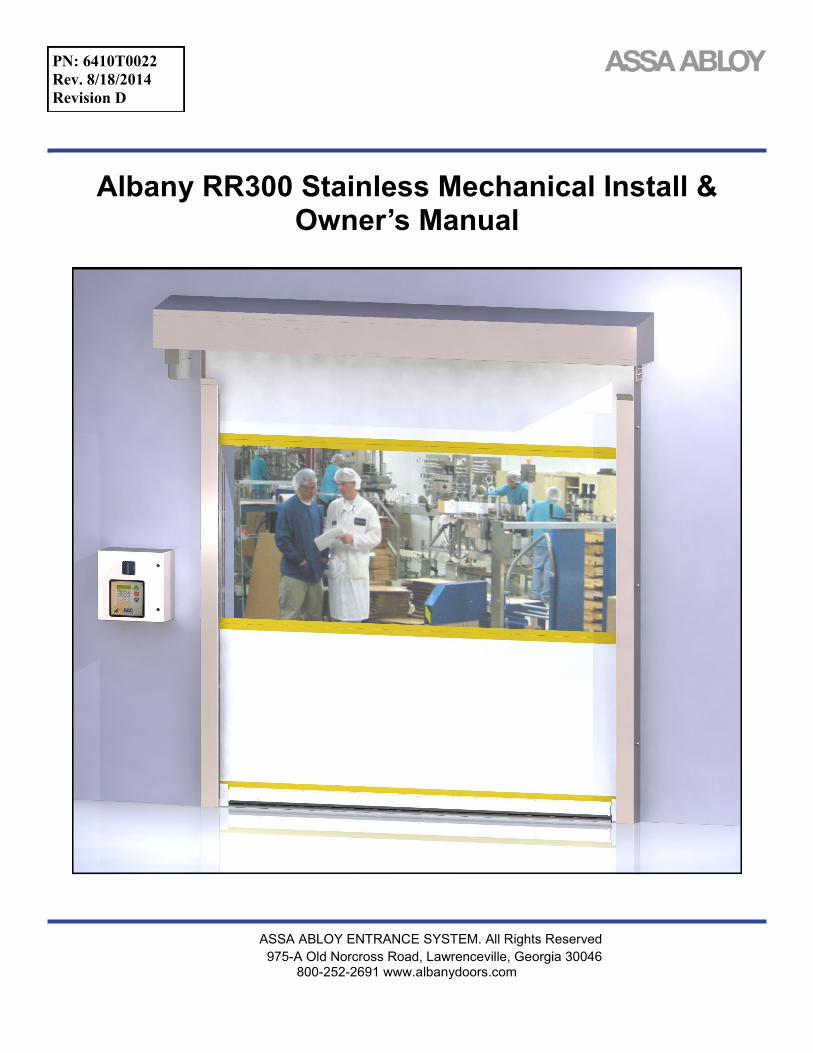
Albany RR300 Stainless Mechanical Install & Owner’s Manual
ASSA ABLOY ENTRANCE SYSTEM. All Rights Reserved
975-A Old Norcross Road, Lawrenceville, Georgia 30046 800-252-2691 www.albanydoors.com
PN: 6410T0022
Rev. 8/18/2014
Revision D

1 Manual #6410T0022 Rev. 8/18/2014
INTRODUCTION
The contents of this manual are designed to help you install and setup ASSA ABLOY Albany RR300 Stain-
less™ high speed doors. DO NOT operate or perform maintenance on the high speed door unless you
have read through the instructions in this manual.
The safety alert symbol is used to identify safety information about hazards that can result in
personal injury. A signal word (DANGER, WARNING, or CAUTION) is used with the
safety alert symbol to indicate the likelihood and the potential severity of injury. In addition,
a hazard symbol may be used to represent the type of hazard.
DANGER indicates a hazard that, if not avoided, will re-
sult in death or serious injury.
WARNING indicates a hazard that, if not avoided, could
result in death or serious injury.
CAUTION indicates a hazard that, if not avoided, might
result in minor or moderate injury.
CAUTION, when used without the alert symbol, indicates
a situation that could result in damage to the door.
NOTICE is used to inform you of a method, reference, or
procedure that could assist with specific operations or
procedures.
Other symbols that may be used in this manual are:
Lock Out / Tag Out Crushing Fire Shock Read Manual

Revision D Manual #6410T0022 2
ASSA ABLOY High Performance Doors
Installation & Operation
DOOR INSTALLATION
Lock-Out Tag-out all electrical power supplied to the door before making any electrical installations or connections. Also Lock-out Tag-out any equipment near the installation site if that equipment may be inadvertently operated into the area used to assem-ble and install the door. Failure to properly de-energize electrical circuits and disable equipment during installation and/or maintenance could result in death or serious injury.
Improper installation of anchoring devices or installa-tion into aged or unsound concrete block, or other wall material may result in premature wear, product failure, property damage, or serious personal injury.
Use proper lifting equipment and techniques. Properly secure all loads. Failure to properly secure all lifting loads could result in death or serious injury.
Secure the work area so that persons not working directly on the installation do not enter the work area.
TOOLS AND MATERIALS REQUIRED
Personnel
Two people to install the door
One person qualified to operate forklift, hoist, or crane
One electrician to install and connect the control panel and all electrical wiring
Tools
Assorted wrenches
Tape measure
Carpenter’s square
Level (4ft minimum recommended)
Lifting device (fork lift, hoist, crane)
Lifting Straps
2 ladders or personnel lifts (tall enough to reach above the door head)
Other tools as needed for the type of anchor-ing chosen
Materials
Anchors appropriate for the type of wall the door and accessories are to be installed on-to. Albany Doors recommends through-bolting doors whenever possible.
Wire as specified on the electrical schematic
Electrical supplies needed to comply with all regulating body electrical codes and stand-ards.
SITE PREPARATION
Electrical Supply Qualified electrician must make all electrical mountings and connections in accordance with all applicable regulating body(s) electrical codes and standards. See applicable electrical manual for specifications and wiring instructions.
Door Opening 1. Are the door jambs and support wall structur-
ally sound providing a flat surface for the side columns to mount against?
2. Check the width and height of the door open-ing and verify the measurements against the dimensions of the door.
3. Is the opening square? Plumb? 4. Is the floor level across the opening?
Make all necessary structural repairs and improvements to provide a “yes” answer to each of the questions above.
UNPACKING AND PREPARING
1. Inspect and unpack the components. Report any damage immediately to ASSA ABLOY at 877-925-2468. Refer to the serial number tag located on the right door column.
2. DO NOT cut the banding which holds the door in a roll until instructed to do so in a later procedure.
The door panel and roll assembly could be damaged. Use evenly spaced padded supports to prevent rips, tears, or bending of the roll assembly. Failure to pro-tect the roll assembly could result in damage to the door.
3 Manual #6410T0022 Rev. 8/18/2014
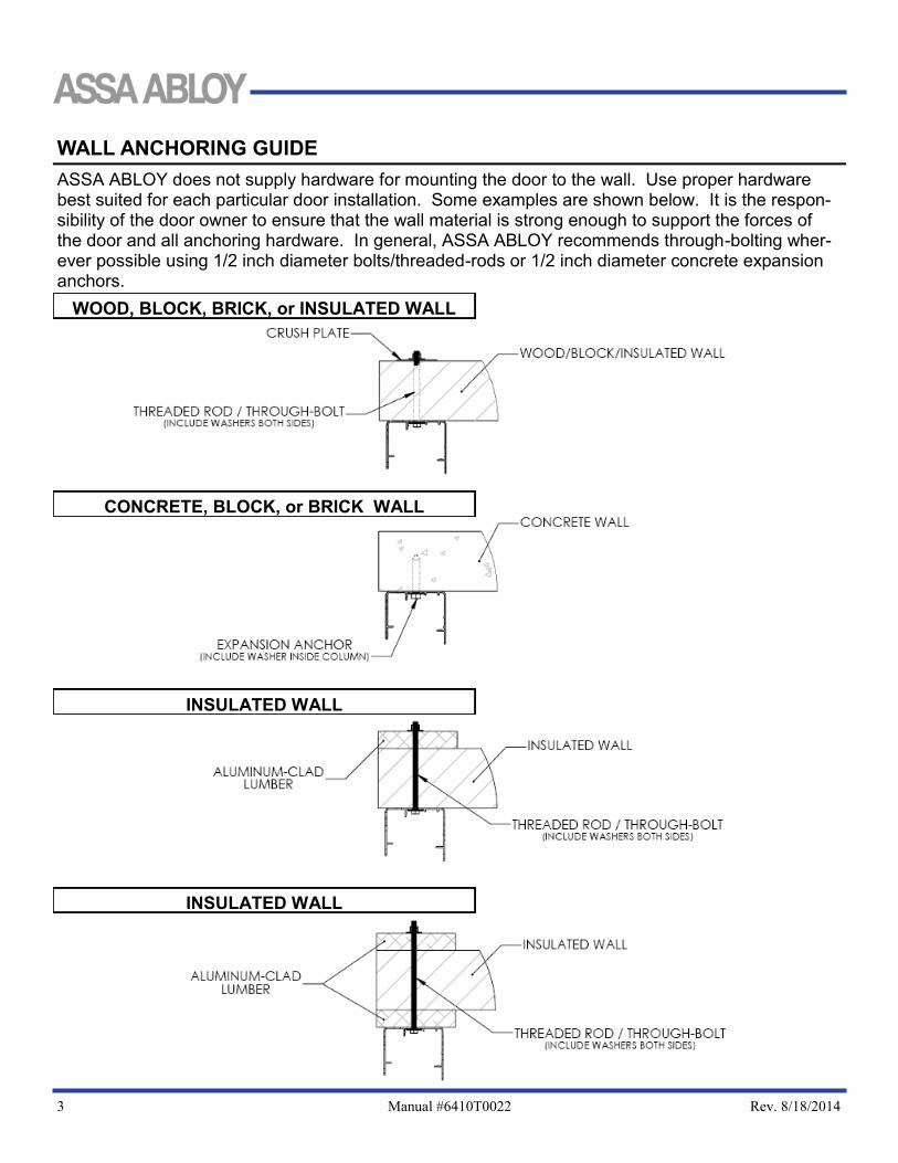
WALL ANCHORING GUIDE
INSULATED WALL
INSULATED WALL
CONCRETE, BLOCK, or BRICK WALL
WOOD, BLOCK, BRICK, or INSULATED WALL
ASSA ABLOY does not supply hardware for mounting the door to the wall. Use proper hardware best suited for each particular door installation. Some examples are shown below. It is the respon-sibility of the door owner to ensure that the wall material is strong enough to support the forces of the door and all anchoring hardware. In general, ASSA ABLOY recommends through-bolting wher-ever possible using 1/2 inch diameter bolts/threaded-rods or 1/2 inch diameter concrete expansion anchors.

Revision D Manual #6410T0022 4
ASSA ABLOY High Performance Doors
Installation & Operation
INSTALLATION REFERENCE MARKS
1. Measure from the inside of the left door jamb to the inside of the right door jamb and place a mark on the floor on the door opening centerline.
2. Reference the door’s documentation and place two marks on
the floor at
to the left and to the right of the door opening centerline. 3. Measure the distance between the two new marks. The cor-
rect distance should be equal to the ordered door width.
2
DoorWidth
2
DoorWidth
2
DoorWidth

5 Manual #6410T0022 Rev. 8/18/2014
MOUNTING THE DOOR ASSEMBLY
ASSEMBLE ON WALL
1. Hold the left side column in place against the wall. Align the base with the marking placed on the floor earlier and bring the column into plumb.
2. Mark the locations of the mounting holes. Prepare the holes and anchor as needed.
3. Loosely install the anchors, recheck for plumb, and tighten the anchors.
4. Repeat steps 1-3 for the right side column.
5. Lay the head assembly on its back on the floor in front of the door opening. Using a safe lifting device, carefully lift the head assembly up into position above the side columns.
7. Position the drum assembly in front of the side columns with the drum shafts in line with the mounting brackets on the side columns and carefully set it into place.
8. Install the two 1/2” flat washers, lock washers, and 1/2”x1” bolts on each bearing on each side of the head assembly to secure it in place.
9. The photo safety cables are marked and bundled on top of the head assembly at the junction box. Route the light curtain cables through the rear of the side column. Note that the wire will enter the top opening of the left side col-umn, while the right side column utilizes a hole in the side of the column.
The drum assembly is heavy. Use proper lifting devices and techniques to securely and safely lift the drum as-sembly. Failure to properly secure the drum assembly could result in death or serious injury.
The drum assembly must be lifted level (balanced) and with the motor hanging straight down. Failure to proper-ly position the drum assembly could result in damage to the mounting brackets and/or the side columns.
Top-Down View Left Side Column
Top-Down View Right Side Column

Revision D Manual #6410T0022 6
ASSA ABLOY High Performance Doors
Installation & Operation
10. Plug the wires into the appropriate photo device mounted in the column—note the matching cable mark-ings. For light curtains, the transmitter will be on the right side and the receiver will be on the left. Ensure that all loose slack in the cables is removed.
11. Set the inner side columns into the outer side columns. If the door was ordered with photo eyes, position the front photo eye mounting brackets against the outside of the side columns and secure them with two self-tapping stainless steel sheet metal screws. Install the knurled hand knobs on the remaining studs protrud-ing through the outside faces of the side columns.
12. Connect the remaining safety cables to the photo safety devices mounted on the outside of the columns and
rear side of the door if applicable—note the matching cable markings.
13. Install head seals as shown below.
14. Caulk header and door jambs to seal the opening when finished.
15. See the applicable electrical manual for wiring and startup instructions that was included with the door.

7 Manual #6410T0022 Rev. 8/18/2014
Installing Manual Hoist Brake Release—Optional equipment
Doors equipped with a manual chain hoist will require the installation of a mechanical brake release rod that when actuated will pull down on the manual brake release rod of the motor so that hoisting the door can be performed without having to drive thru the brake of the motor.
Install the ‘Z’ bracket to chain hoist housing. Use the nut and bolt to secure bracket to
housing.
Locate the brake release cable, hose clamp, one 8-32x1/2” bolt and 8-32 Nyloc nut.
Install hose clamp to brake release cable. Place
hose clamp approximately 30mm away from
end of cable sheath.
Install 8-32x1/2” bolt into the hose clamp
Place exposed end of brake release cable through the thru-hole on brake release arm.
Install brake release cable assembly to the ‘Z’ bracket.

Revision D Manual #6410T0022 8
ASSA ABLOY High Performance Doors
Installation & Operation
Fasten the 8-32 nut to bolt to secure hose clamp to ’Z’ bracket.
T-handle must be in the fully retracted position during the install and mounting process.
Verify the brake release arm is in the ‘Disengaged’ or upper
position.
Install cable clamp to the exposed end of brake release cable
and tighten the two nuts to secure clamp.
The T-handle mounting bracket can now be wall mount to desired height. Once mounted you will need to verify the functionality of the brake release cable along with the functioning of the manual hoist. If the release rod is working properly the hoist should require little effort to operate. Improper adjustment of the brake release will allow the brake to drag during the hoisting of the door.
It is imperative that you verify the electrical interlock function of the hoist. When the hoist is engaged (red handle pulled down) the hoist disengagement switch will open and if properly connected to the control will act as a stop input function disabling the control from operating the door electrically. The control system should not be able to electrically function the door while the hoist is engaged. Refer to the schematics supplied with the door for hoist interlock switch wiring.

9 Manual #6410T0022 Rev. 8/18/2014

Revision D Manual #6410T0022 10
ASSA ABLOY High Performance Doors
Installation & Operation

11 Manual #6410T0022 Rev. 8/18/2014
Hood Mounting Instructions
Mark a level horizontal line on the wall 18” above door open-
ing.
Space brackets evenly across door opening at marked height.
Leave a 12” gap between Z-brackets near centerline of door.
Permanently attach Z-brackets to wall placing the bottom of the
brackets on the placement line.
Assemble hood using self-threading screws as shown in the
exploded views. Hang the hood assembly on the mounting
brackets and secure

Revision D Manual #6410T0022 12
ASSA ABLOY High Performance Doors
Installation & Operation
Periodic Maintenance ASSA ABLOY high speed doors are engineered for low maintenance operation. The door should be visually inspected daily for wear and tear, and operated to verify functions. Quarterly maintenance should be performed to clean compo-nents and to check all safety functions and check for mechanical and electrical integrity. Daily Inspection
1. Inspect the door fabric for wear or damage.
2. Operate the door through several openings and closings. Verify that the door seats against the floor and that the door fabric remains tight and does not wrinkle. Verify that the door opens fully, slightly beyond the wall opening, and does not open too far.
If the door does not seat against the floor properly or opens to the wrong position, refer to “Setting Door Lim-
it Adjustments”.
If the door fabric has diagonal wrinkles the door fabric roll at the top of the door is not level and perpendicu-
lar to the side rails. Leveling adjustments should be made as soon as possible to prevent wear or damage. Refer to the installation instructions or contact Albany Door Systems.
3. With the door closing, place an object through the light curtain, or photoeyes, on each side of the door. Verify that the door stops immediately.
4. If a multiple panel door is installed, check at each end of the ribs to verify that they are in place and centered.
5. Inspect the coiled electrical wire for wear or damage if equipped.
6. Check the light curtain slots for dirt or dust accumulation and clean as necessary.
7. While the door is closing, tap the bottom of the door edge wand verify that the door stops and reverses to a fully open position.
Do not stand under the door when performing the following inspection. If the bottom bar reversing switch is not functioning correctly injury can occur.
8. Perform daily inspection.
9. Check all mounting hardware and verify that all nuts and bolts are tight. Hardware includes: wall anchors, cover hardware, motor mounting hardware, and bearing bolt nuts.
10. Check the break away function by performing the following steps:
Stop the door so the bottom rail is between waist and chest high.
Push the bottom bar out of one of the side columns.
Press the open key pad and verify that the door opens to the break away opening height and that the bottom
bar centers in the side rails.
Press the close key pad and verify that the bottom rail is centered and the door closes fully.
11. Inspect all side and top weather seals for wear or damage.

13 Manual #6410T0022 Rev. 8/18/2014
HOOD ASSEMBLY PART# 001225 1-PIECE CONFIGURATION
HOOD ASSEMBLY PART# 001225 2-PIECE CONFIGURATION

Revision D Manual #6410T0022 14
ASSA ABLOY High Performance Doors
Installation & Operation
Installation Checklist
Please fill out below and return to ASSA ABLOY Entrance Systems
Customer: Installation Date(s):
Location: Door Serial #(‘s):
Contact: Contact Phone #:
Install Company: Contact & Phone #:
Mechanical Installation (All Doors): Yes No
Is the door secured to the wall using thru-bolts?
If No, what type of anchors were used?
Is the door roll level?
Are the side columns plumb?
Is the door caulked or sealed to the wall?
Are there any visible gaps between the door and the wall?
If “No” the above, did the customer contact approve of door to wall seal?
Is there any visible damage to the door?
If Yes, what is the damage:
Was Albany Customer Service notified of the damage?
Was the customer contact notified of the damage?
Electrical Installation: Yes No
Were the factory supplied cables (motor, encoder & 7 – wire) cables long enough?
If No, which cables were too short?
If No, was Albany Customer Support contacted and new cables sent?
Were the schematics easy to read for electrical hook-up?
What type of conduit was used to route the cables to the door?
Is the conduit routed to the bottom of the control box?
If “No” did the customer approve this?
If “No,” why?
If “Yes,” who was the customer contact that approved?
15 Manual #6410T0022 Rev. 8/18/2014
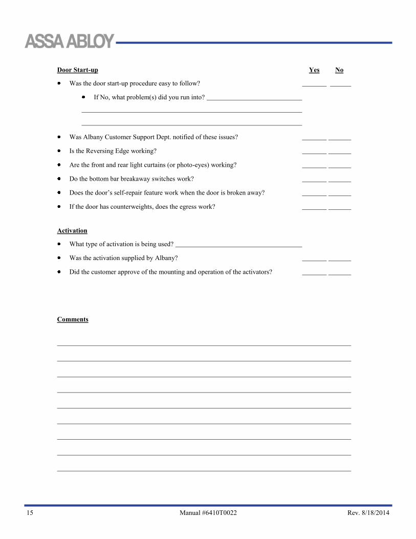
Door Start-up Yes No
Was the door start-up procedure easy to follow?
If No, what problem(s) did you run into?
Was Albany Customer Support Dept. notified of these issues?
Is the Reversing Edge working?
Are the front and rear light curtains (or photo-eyes) working?
Do the bottom bar breakaway switches work?
Does the door’s self-repair feature work when the door is broken away?
If the door has counterweights, does the egress work?
Activation
What type of activation is being used?
Was the activation supplied by Albany?
Did the customer approve of the mounting and operation of the activators?
Comments

ASSA ABLOY ENTRANCE SYSTEM. . All Rights Reserved
975-A Old Norcross Road, Lawrenceville, Georgia 30046 800-252-2691 www.albanydoors.com