alcatel-lucent 1354 bm-atm | release 7.1 operator's … 86577 abaa ed3 1/725 all rights...
TRANSCRIPT

Alcatel-Lucent
1354 BM-ATM | Release 7.1
Operator's Handbook
3AG86577ABAATQZZA
July 2006Issue 3

3AG 86577 ABAA Ed3 1/725
All r
ight
s res
erve
d. P
ass
ing
on
and
cop
ying
of t
his
doc
umen
t, us
e a
nd c
omm
unic
atio
n o
f its
con
tent
sno
t per
mitt
ed w
ithou
t writ
ten
aut
horis
atio
n fro
mA
lca
tel
Ed 3: 2006-07-25
O P E R A T O R ’ SH A N D B O O K
1354 BM ATM Rel. 7.1B r o a d b a n d M a n a g e r o fA T M b o a r d s i n O M S N

3AG 86577 ABAA Ed3 2/725
All r
ight
s res
erve
d. P
ass
ing
on
and
cop
ying
of t
his
doc
umen
t, us
e a
nd c
omm
unic
atio
n o
f its
con
tent
sno
t per
mitt
ed w
ithou
t writ
ten
aut
horis
atio
n fro
mA
lca
tel

3AG 86577 ABAA Ed3 3/725
All r
ight
s res
erve
d. P
ass
ing
on
and
cop
ying
of t
his
doc
umen
t, us
e a
nd c
omm
unic
atio
n o
f its
con
tent
sno
t per
mitt
ed w
ithou
t writ
ten
aut
horis
atio
n fro
mA
lca
tel
Contents1 GENERALITIES................................................................................................................................. 24
1.1 OVERVIEW .................................................................................................................................... 251.1.1 Management layers .................................................................................................................. 261.1.2 Positioning............................................................................................................................... 271.1.3 The network from various points of view................................................................................... 28
1.2 INTERFACES .................................................................................................................................. 311.2.1 1354 BM 1353 NM interface.................................................................................................. 321.2.2 1354 BM 1354 RM interface.................................................................................................. 32
1.3 ATM BASIC CONCEPTS .................................................................................................................. 331.3.1 Cell.......................................................................................................................................... 331.3.2 Transmission path, VP and VC................................................................................................. 331.3.3 Inverse Multiplexing ATM (IMA).............................................................................................. 341.3.4 ATM connection....................................................................................................................... 351.3.5 Quality of service ..................................................................................................................... 36
1.4 FUNCTIONAL DOMAINS .................................................................................................................. 381.4.1 Network construction ............................................................................................................... 38
1.4.1.1 Sub-network.................................................................................................................................. 391.4.1.2 ATM NE and ENE ........................................................................................................................ 401.4.1.3 Transmission path, IMA transmission path (IMA group), IMA link................................................. 401.4.1.4 ATM termination and ETP............................................................................................................. 411.4.1.5 Transmission path / IMA transmission path partition ...................................................................... 44
1.4.2 Network management............................................................................................................... 471.4.2.1 Hard PVC ..................................................................................................................................... 481.4.2.2 Soft PVC....................................................................................................................................... 481.4.2.3 Routing management..................................................................................................................... 501.4.2.4 UPC/NPC management ................................................................................................................. 511.4.2.5 Output shaping.............................................................................................................................. 511.4.2.6 Point-to-multi-points PVC management ......................................................................................... 521.4.2.7 Overbooking management ............................................................................................................. 56
1.4.3 Maintenance management........................................................................................................ 581.4.3.1 Fault management ......................................................................................................................... 581.4.3.2 OAM management ........................................................................................................................ 64
1.4.4 Performance management........................................................................................................ 661.4.5 Administration management ..................................................................................................... 67
1.4.5.1 PNNI management ........................................................................................................................ 681.4.5.2 ATM Traffic management ............................................................................................................. 691.4.5.3 VN management............................................................................................................................ 69
1.4.6 Utilities.................................................................................................................................... 701.4.6.1 Plug & play................................................................................................................................... 701.4.6.2 NE audit........................................................................................................................................ 711.4.6.3 NE alignment ................................................................................................................................ 711.4.6.4 NE force alignment ....................................................................................................................... 72
1.4.7 System management ................................................................................................................. 731.4.7.1 Operator profile management......................................................................................................... 73
1.5 SYSTEM ENVIRONMENT ................................................................................................................. 751.5.1 General environment................................................................................................................ 751.5.2 User interface .......................................................................................................................... 75
2 USER INTERFACE OVERVIEW...................................................................................................... 76
2.1 GENERALITIES .............................................................................................................................. 772.1.1 Vocabulary used in the user interface ....................................................................................... 782.1.2 User interface windows ............................................................................................................ 79
2.1.2.1 Main view..................................................................................................................................... 802.1.2.2 Graphical views............................................................................................................................. 812.1.2.3 List windows................................................................................................................................. 832.1.2.4 Data display windows.................................................................................................................... 862.1.2.5 Data acquisition windows .............................................................................................................. 872.1.2.6 Dialog and message boxes ............................................................................................................. 88
2.1.3 Window management ............................................................................................................... 902.1.4 Selection rules.......................................................................................................................... 912.1.5 String character agreement ...................................................................................................... 92

3AG 86577 ABAA Ed3 4/725
All r
ight
s res
erve
d. P
ass
ing
on
and
cop
ying
of t
his
doc
umen
t, us
e a
nd c
omm
unic
atio
n o
f its
con
tent
sno
t per
mitt
ed w
ithou
t writ
ten
aut
horis
atio
n fro
mA
lca
tel
2.1.6 Sensitive help ........................................................................................................................... 922.1.7 Buttons .................................................................................................................................... 95
2.1.7.1 Option buttons............................................................................................................................... 952.1.7.2 Radio buttons ................................................................................................................................ 95
2.2 GETTING STARTED ........................................................................................................................ 962.2.1 Starting the 1354 BM GUI........................................................................................................ 96
2.2.1.1 On an HP workstation.................................................................................................................... 962.2.1.2 On a PC ........................................................................................................................................ 98
2.2.2 Starting the Command Line Interface (CLI) ............................................................................ 1002.2.3 Starting the Alarm Surveillance GUI ...................................................................................... 1012.2.4 Starting the performance monitoring GUI .............................................................................. 103
2.3 ADMINISTERING THE 1354 BM .................................................................................................... 1142.3.1 List of EML-IM ...................................................................................................................... 115
2.3.1.1 Add an EML-IM ......................................................................................................................... 1162.3.1.2 Remove an EML-IM ................................................................................................................... 117
2.3.2 Set the 1354 BM configuration parameters ............................................................................. 1182.3.3 Display 1354 BM log file........................................................................................................ 120
2.4 MAIN VIEW ................................................................................................................................. 1222.4.1 Using the tree......................................................................................................................... 124
2.5 ACCESSING THE FUNCTIONS......................................................................................................... 1282.5.1 From the menus ..................................................................................................................... 1282.5.2 From the icons ....................................................................................................................... 1292.5.3 General toolbar ..................................................................................................................... 130
2.5.3.1 Contextual toolbar ....................................................................................................................... 1312.5.4 From the contextual menu ...................................................................................................... 1322.5.5 From the tree ......................................................................................................................... 1332.5.6 Conventions ........................................................................................................................... 133
2.6 WINDOW MENU ........................................................................................................................... 1342.6.1 Arrange the windows.............................................................................................................. 1342.6.2 Choose the active window ...................................................................................................... 141
2.7 MAIN MENU ................................................................................................................................ 1422.8 VIEW MENU ................................................................................................................................ 143
2.8.1 Select a background map........................................................................................................ 1442.8.2 Save a sub-network or global view.......................................................................................... 1452.8.3 Network representation.......................................................................................................... 1462.8.4 Selection rules in a graphical view ......................................................................................... 1482.8.5 Sub-network views ................................................................................................................. 148
2.8.5.1 Sub-network views in transmission path domain........................................................................... 1492.8.5.2 Sub-network views in VP domain ................................................................................................ 1512.8.5.3 Sub-network views in VC domain................................................................................................ 1532.8.5.4 Open a sub-network..................................................................................................................... 1552.8.5.5 Open a grouped link .................................................................................................................... 1562.8.5.6 Navigate through an off-page connector ....................................................................................... 157
2.8.6 Global views .......................................................................................................................... 1582.8.6.1 Global views in transmission path domain.................................................................................... 1592.8.6.2 Global views in VP domain ......................................................................................................... 1602.8.6.3 Global views in VC domain......................................................................................................... 1612.8.6.4 Open / close a sub-network.......................................................................................................... 162
2.9 HELP MENU................................................................................................................................. 1642.9.1 General help .......................................................................................................................... 1652.9.2 Contextual help...................................................................................................................... 168
3 NETWORK CONSTRUCTION........................................................................................................ 170
3.1 MANAGING SUB-NETWORKS ........................................................................................................ 1723.1.1 Display the sub-network list ................................................................................................... 1733.1.2 Create a sub-network ............................................................................................................. 1753.1.3 Modify a sub-network............................................................................................................. 1773.1.4 Delete a sub-network.............................................................................................................. 1783.1.5 Get the sub-networks properties ............................................................................................. 179
3.2 MANAGING NES.......................................................................................................................... 1803.2.1 Display the NE list ................................................................................................................. 1813.2.2 Define a NE ........................................................................................................................... 184

3AG 86577 ABAA Ed3 5/725
All r
ight
s res
erve
d. P
ass
ing
on
and
cop
ying
of t
his
doc
umen
t, us
e a
nd c
omm
unic
atio
n o
f its
con
tent
sno
t per
mitt
ed w
ithou
t writ
ten
aut
horis
atio
n fro
mA
lca
tel
3.2.2.1 Display the available NE list ........................................................................................................ 1843.2.2.2 Add a NE.................................................................................................................................... 186
3.2.3 Modify a NE........................................................................................................................... 1883.2.4 Delete a NE ........................................................................................................................... 1893.2.5 Upload the NE terminations ................................................................................................... 1903.2.6 Synchronize the NE terminations ............................................................................................ 1913.2.7 Acquit the NE LAC state......................................................................................................... 1923.2.8 Display the termination list .................................................................................................... 1933.2.9 Audit the NE terminations ...................................................................................................... 1953.2.10 Configure a termination..................................................................................................... 1973.2.11 De-configure a termination................................................................................................ 1983.2.12 Get the NE properties ........................................................................................................ 1993.2.13 Show equipment view......................................................................................................... 200
3.3 MANAGING ENES ....................................................................................................................... 2013.3.1 Display the ENE list ............................................................................................................... 2023.3.2 Create an ENE....................................................................................................................... 2043.3.3 Modify an ENE ...................................................................................................................... 2063.3.4 Delete an ENE ....................................................................................................................... 2073.3.5 Display the ETP list ............................................................................................................... 2083.3.6 Create ETPs........................................................................................................................... 2103.3.7 Delete an ETP........................................................................................................................ 2113.3.8 Assign NAD Label to ETPs..................................................................................................... 2133.3.9 Get the ENE properties .......................................................................................................... 214
3.4 MANAGING TRANSMISSION PATHS / IMA TRANSMISSION PATHS.................................................... 2153.4.1 Display the transmission paths list.......................................................................................... 2173.4.2 Create a transmission path..................................................................................................... 2213.4.3 Display the IMA link list......................................................................................................... 227
3.4.3.1 Add an IMA link to an IMA transmission path ............................................................................. 2293.4.3.2 Remove an IMA link from an IMA transmission path................................................................... 2313.4.3.3 Finalize an IMA link ................................................................................................................... 2333.4.3.4 Display the IMA link extremities ................................................................................................. 2343.4.3.5 Display the IMA link properties................................................................................................... 2353.4.3.6 Display the fault localization........................................................................................................ 236
3.4.4 Finalize a transmission path................................................................................................... 2383.4.5 Finalize an IMA transmission path ......................................................................................... 2393.4.6 Modify a transmission path .................................................................................................... 2403.4.7 Delete a transmission path ..................................................................................................... 2423.4.8 Lock a transmission path........................................................................................................ 2443.4.9 Unlock a transmission path .................................................................................................... 2463.4.10 Configure a transmission path ........................................................................................... 2473.4.11 Configure NIM for a transmission path.............................................................................. 2493.4.12 Partition a transmission path............................................................................................. 250
3.4.12.1 Explanation about the transmission path partitioning .................................................................... 2533.4.13 Display the transmission path extremities........................................................................... 2553.4.14 Display the transmission path bandwidth load ................................................................... 257
3.4.14.1 For hard routing service............................................................................................................... 2583.4.14.2 For soft routing service ................................................................................................................ 260
3.4.15 Display the fault localization ............................................................................................. 2613.4.16 Display the transmission path properties............................................................................ 263
4 NETWORK MANAGEMENT.......................................................................................................... 265
4.1 MANAGING HARD PVPCS ............................................................................................................ 2674.1.1 Display the hard PVPC list..................................................................................................... 2704.1.2 Define a hard PVPC............................................................................................................... 2754.1.3 Modify a hard PVPC.............................................................................................................. 2804.1.4 Delete a hard PVPC............................................................................................................... 2824.1.5 Allocate a hard PVPC............................................................................................................ 2834.1.6 De-allocate a hard PVPC....................................................................................................... 2874.1.7 Implement a hard PVPC......................................................................................................... 2894.1.8 De-implement a hard PVPC ................................................................................................... 2914.1.9 Commission a hard PVPC...................................................................................................... 2934.1.10 De-commission a hard PVPC............................................................................................. 294

3AG 86577 ABAA Ed3 6/725
All r
ight
s res
erve
d. P
ass
ing
on
and
cop
ying
of t
his
doc
umen
t, us
e a
nd c
omm
unic
atio
n o
f its
con
tent
sno
t per
mitt
ed w
ithou
t writ
ten
aut
horis
atio
n fro
mA
lca
tel
4.1.11 Lock a hard PVPC............................................................................................................. 2954.1.12 Unlock a hard PVPC ......................................................................................................... 2964.1.13 Assign NAD Label to a hard PVPC.................................................................................... 2974.1.14 Activate the output shaping on a hard PVPC...................................................................... 2984.1.15 Deactivate the output shaping on a hard PVPC.................................................................. 3004.1.16 Activate UPC / NPC on a hard PVPC ................................................................................ 3014.1.17 Deactivate UPC / NPC on a hard PVPC ............................................................................ 3024.1.18 Activate CC on a hard PVPC............................................................................................. 3034.1.19 Deactivate CC on a hard PVPC......................................................................................... 3054.1.20 Modify the bandwidth of a hard PVPC............................................................................... 3074.1.21 Display the hard PVPC extremities.................................................................................... 3104.1.22 Display the hard PVPC properties ..................................................................................... 3124.1.23 Display the hard PVPC bandwidth load............................................................................. 3144.1.24 Display the hard PVPC traffic properties........................................................................... 3174.1.25 Display the hard PVPC routing properties......................................................................... 3184.1.26 Display the hard PVPC graphical view.............................................................................. 3194.1.27 Display the fault localization on hard PVPC ...................................................................... 3214.1.28 Display the hard PVPC NE NIM list .................................................................................. 323
4.1.28.1 Configure / de-configure the hard PVPC NE NIMs....................................................................... 3254.1.29 Display hard PVPC NIM CC list........................................................................................ 327
4.1.29.1 Activate NIM CC ........................................................................................................................ 3294.1.29.2 Deactivate NIM CC..................................................................................................................... 330
4.1.30 Display the hard PVPC Constraints list ............................................................................. 3314.1.30.1 Add a constraint to a hard PVPC.................................................................................................. 3334.1.30.2 Delete a constraint from a hard PVPC.......................................................................................... 335
4.2 MANAGING HARD PVPC LEGS .................................................................................................... 3364.2.1 Display the hard PVPC Leg list.............................................................................................. 3394.2.2 Show the associated Legs ....................................................................................................... 3424.2.3 Define a hard PVPC Leg........................................................................................................ 3434.2.4 Modify a hard PVPC Leg ....................................................................................................... 3454.2.5 Delete a hard PVPC Leg ........................................................................................................ 3464.2.6 Allocate a hard PVPC Leg ..................................................................................................... 3474.2.7 De-allocate a hard PVPC Leg ................................................................................................ 3504.2.8 Implement a hard PVPC Leg.................................................................................................. 3514.2.9 De-implement a hard PVPC Leg............................................................................................. 3524.2.10 Commission a hard PVPC Leg........................................................................................... 3534.2.11 De-commission a hard PVPC Leg...................................................................................... 3544.2.12 Display the hard PVPC Leg extremities ............................................................................. 3554.2.13 Display the hard PVPC Leg properties .............................................................................. 3564.2.14 Display the hard PVPC Leg routing properties .................................................................. 3574.2.15 Display the hard PVPC Leg graphical view ....................................................................... 3584.2.16 Display the hard PVPC Leg NE NIM list............................................................................ 360
4.2.16.1 Configure / de-configure the hard PVPC Leg NE NIMs................................................................ 3624.2.17 Display the hard PVPC Leg Constraints list....................................................................... 364
4.2.17.1 Add a constraint to a hard PVPC Leg ........................................................................................... 3664.2.17.2 Delete a constraint from a hard PVPC Leg ................................................................................... 368
4.3 MANAGING HARD PVCCS ........................................................................................................... 3694.3.1 Display the hard PVCC list .................................................................................................... 3724.3.2 Define a hard PVCC .............................................................................................................. 3764.3.3 Modify a hard PVCC.............................................................................................................. 3824.3.4 Delete a hard PVCC............................................................................................................... 3844.3.5 Allocate a hard PVCC............................................................................................................ 3854.3.6 De-allocate a hard PVCC....................................................................................................... 3894.3.7 Implement a hard PVCC ........................................................................................................ 3904.3.8 De-implement a hard PVCC................................................................................................... 3924.3.9 Commission a hard PVCC...................................................................................................... 3944.3.10 De-commission a hard PVCC ............................................................................................ 3954.3.11 Assign NAD Label to a hard PVCC.................................................................................... 3964.3.12 Activate UPC / NPC on a hard PVCC................................................................................ 3974.3.13 Deactivate UPC / NPC on a hard PVCC............................................................................ 3984.3.14 Activate CC on a hard PVCC............................................................................................. 399

3AG 86577 ABAA Ed3 7/725
All r
ight
s res
erve
d. P
ass
ing
on
and
cop
ying
of t
his
doc
umen
t, us
e a
nd c
omm
unic
atio
n o
f its
con
tent
sno
t per
mitt
ed w
ithou
t writ
ten
aut
horis
atio
n fro
mA
lca
tel
4.3.15 Deactivate CC on a hard PVCC......................................................................................... 4014.3.16 Modify the bandwidth of a hard PVCC............................................................................... 4034.3.17 Display the hard PVCC extremities.................................................................................... 4064.3.18 Display the hard PVCC properties..................................................................................... 4084.3.19 Display the hard PVCC traffic properties........................................................................... 4094.3.20 Display the hard PVCC routing properties......................................................................... 4104.3.21 Display the hard PVCC graphical view.............................................................................. 4114.3.22 Display the fault localization on a hard PVCC................................................................... 4134.3.23 Display hard PVCC NE NIM list........................................................................................ 415
4.3.23.1 Configure / de-configure the hard PVCC NE NIMs ...................................................................... 4174.3.24 Display hard PVCC NIM CC list ....................................................................................... 419
4.3.24.1 Activate NIM CC ........................................................................................................................ 4214.3.24.2 Deactivate NIM CC..................................................................................................................... 422
4.3.25 Display hard PVCC Constraints list................................................................................... 4234.3.25.1 Add a constraint to a hard PVCC ................................................................................................. 4254.3.25.2 Delete a constraint from a hard PVCC.......................................................................................... 427
4.4 MANAGING HARD PVCC LEGS .................................................................................................... 4284.4.1 Display the hard PVCC Leg list.............................................................................................. 4314.4.2 Show associated Legs............................................................................................................. 4344.4.3 Define a hard PVCC Leg........................................................................................................ 4354.4.4 Modify a hard PVCC Leg ....................................................................................................... 4374.4.5 Delete a hard PVCC Leg........................................................................................................ 4384.4.6 Allocate a hard PVCC Leg ..................................................................................................... 4394.4.7 De-allocate a hard PVCC Leg................................................................................................ 4424.4.8 Implement a hard PVCC Leg.................................................................................................. 4434.4.9 De-implement a hard PVCC Leg ............................................................................................ 4454.4.10 Commission a hard PVCC Leg........................................................................................... 4474.4.11 De-commission a hard PVCC Leg...................................................................................... 4484.4.12 Display the hard PVCC Leg extremities ............................................................................. 4494.4.13 Display the hard PVCC Leg properties .............................................................................. 4504.4.14 Display the hard PVCC Leg routing properties .................................................................. 4514.4.15 Display the hard PVCC Leg graphical view ....................................................................... 4524.4.16 Display the hard PVCC Leg NE NIM list ........................................................................... 454
4.4.16.1 Configure the hard PVCC Leg NE NIMs...................................................................................... 4564.4.17 Display the hard PVCC Leg Constraint list ........................................................................ 458
4.4.17.1 Add a constraint to a hard PVCC Leg........................................................................................... 4604.4.17.2 Delete a constraint from a hard PVCC Leg................................................................................... 462
4.5 MANAGING SOFT PVPCS ............................................................................................................. 4634.5.1 Display the soft PVPC description list .................................................................................... 4654.5.2 Define a soft PVPC ................................................................................................................ 4684.5.3 Modify a soft PVPC................................................................................................................ 4724.5.4 Delete a soft PVPC ................................................................................................................ 4734.5.5 Set-up a soft PVPC................................................................................................................. 4744.5.6 Release a soft PVPC............................................................................................................... 4764.5.7 Display the soft PVPC characteristic list ................................................................................ 4774.5.8 Activate the output shaping on a soft PVPC ............................................................................ 4804.5.9 Deactivate the output shaping on a soft PVPC ........................................................................ 4824.5.10 Activate UPC / NPC on a soft PVPC.................................................................................. 4834.5.11 Deactivate UPC / NPC on a soft PVPC.............................................................................. 4844.5.12 Display the soft PVPC extremities...................................................................................... 4854.5.13 Display the soft PVPC properties....................................................................................... 4864.5.14 Display the soft PVPC bandwidth load............................................................................... 4874.5.15 Display the soft PVPC traffic properties............................................................................. 4894.5.16 Display the soft PVPC routing properties........................................................................... 4904.5.17 Activate/deactivate the CC on a soft PVPC (change CC direction) ..................................... 4904.5.18 Display the soft PVPC graphical view................................................................................ 490
4.6 MANAGING SOFT PVCCS............................................................................................................. 4914.6.1 Display the soft PVCC description list .................................................................................... 4934.6.2 Define a soft PVCC................................................................................................................ 4964.6.3 Modify a soft PVCC ............................................................................................................... 5004.6.4 Delete a soft PVCC ................................................................................................................ 501

3AG 86577 ABAA Ed3 8/725
All r
ight
s res
erve
d. P
ass
ing
on
and
cop
ying
of t
his
doc
umen
t, us
e a
nd c
omm
unic
atio
n o
f its
con
tent
sno
t per
mitt
ed w
ithou
t writ
ten
aut
horis
atio
n fro
mA
lca
tel
4.6.5 Set-up a soft PVCC ................................................................................................................ 5024.6.6 Release a soft PVCC .............................................................................................................. 5044.6.7 Display the soft PVCC characteristic list ................................................................................ 5054.6.8 Activate UPC / NPC on a soft PVCC ...................................................................................... 5084.6.9 Deactivate UPC / NPC on a soft PVCC .................................................................................. 5094.6.10 Display the soft PVCC extremities ..................................................................................... 5104.6.11 Display the soft PVCC properties....................................................................................... 5114.6.12 Display the soft PVCC traffic properties ............................................................................ 5124.6.13 Display the soft PVCC routing properties .......................................................................... 5134.6.14 Activate/deactivate the CC on a soft PVCC (change CC direction) ..................................... 5134.6.15 Display the soft PVCC graphical view ............................................................................... 513
5 MAINTENANCE MANAGEMENT................................................................................................. 515
6 PERFORMANCE MANAGEMENT ................................................................................................ 520
6.1 GENERALITIES ............................................................................................................................ 5216.1.1 Non-OAM PM management.................................................................................................... 5226.1.2 OAM PM management ........................................................................................................... 523
6.2 MANAGING PM MEASURES ......................................................................................................... 5246.2.1 Display the PM Measure list .................................................................................................. 5266.2.2 Create a PM Measure ............................................................................................................ 5296.2.3 Modify a PM Measure............................................................................................................ 5316.2.4 Delete a PM Measure............................................................................................................. 5336.2.5 Associate a PM Measure to a Periodic Report Profile............................................................. 5346.2.6 Dissociate a PM Measure from a Periodic Report Profile....................................................... 5366.2.7 Activate a PM Measure .......................................................................................................... 5386.2.8 De-activate a PM Measure..................................................................................................... 5406.2.9 Force a data collection........................................................................................................... 5426.2.10 Display the PM Measure properties................................................................................... 5436.2.11 Show performance data ..................................................................................................... 5446.2.12 Display the PM Transport list ............................................................................................ 545
6.2.12.1 Associate a PM Transport to a PM Measure ................................................................................. 5476.2.12.2 Dissociate a PM Transport ........................................................................................................... 553
6.2.13 Display the PP List............................................................................................................ 5546.2.13.1 Associate a PP to a PM transport.................................................................................................. 5576.2.13.2 Dissociate a PP from a PM transport ............................................................................................ 558
6.3 MANAGING PERIODIC REPORT PROFILES ...................................................................................... 5596.3.1 Display the Periodic Report Profile list .................................................................................. 5606.3.2 Create a Periodic Report Profile ............................................................................................ 5626.3.3 Modify a Periodic Report Profile............................................................................................ 5656.3.4 Delete a Periodic Report Profile............................................................................................. 5676.3.5 Display the Periodic Report Profile properties ....................................................................... 568
6.4 MANAGING TCA PROFILES ......................................................................................................... 5706.4.1 Display the TCA Profile list.................................................................................................... 5716.4.2 Display the TCA Profile properties......................................................................................... 572
7 ADMINISTRATION MANAGEMENT............................................................................................ 574
7.1 PNNI MANAGEMENT ................................................................................................................... 5757.1.1 Display the NE list for administration..................................................................................... 5767.1.2 Observe a NE......................................................................................................................... 5787.1.3 Configure the PNNI node ATM address.................................................................................. 5797.1.4 Activate a PNNI node............................................................................................................. 5807.1.5 Deactivate a PNNI node......................................................................................................... 5817.1.6 Display the termination list for administration........................................................................ 5827.1.7 Configure the PNNI interface ATM address............................................................................ 584
7.2 ATM TRAFFIC MANAGEMENT ...................................................................................................... 5867.2.1 Traffic descriptor management............................................................................................... 586
7.2.1.1 Display the traffic descriptor list .................................................................................................. 5887.2.1.2 Create a traffic descriptor............................................................................................................. 5907.2.1.3 Create a traffic descriptor from another one.................................................................................. 5937.2.1.4 Modify a traffic descriptor ........................................................................................................... 594

3AG 86577 ABAA Ed3 9/725
All r
ight
s res
erve
d. P
ass
ing
on
and
cop
ying
of t
his
doc
umen
t, us
e a
nd c
omm
unic
atio
n o
f its
con
tent
sno
t per
mitt
ed w
ithou
t writ
ten
aut
horis
atio
n fro
mA
lca
tel
7.2.1.5 Delete a traffic descriptor............................................................................................................. 5957.2.2 Traffic profile management .................................................................................................... 595
7.2.2.1 Traffic profile list ........................................................................................................................ 5977.2.2.2 Create a traffic profile.................................................................................................................. 5997.2.2.3 Create a traffic profile from another one....................................................................................... 6017.2.2.4 Modify a traffic profile ................................................................................................................ 6027.2.2.5 Delete a traffic profile.................................................................................................................. 6037.2.2.6 Display the traffic profile properties............................................................................................. 604
7.3 OPERATOR PROFILE MANAGEMENT .............................................................................................. 605
8 UTILITIES ........................................................................................................................................ 609
8.1 PLUG & PLAY.............................................................................................................................. 6108.1.1 Start the plug & play .............................................................................................................. 6138.1.2 Upload the SDH transmission Paths....................................................................................... 6178.1.3 Discover the transmission path characteristics ....................................................................... 6188.1.4 Discover the traffic descriptors............................................................................................... 6208.1.5 Discover the VP connections .................................................................................................. 6218.1.6 Recover the hard PVPCs ........................................................................................................ 6238.1.7 Discover the VC connections.................................................................................................. 6258.1.8 Recover the hard PVCCs........................................................................................................ 6278.1.9 Clean-up the terminations ...................................................................................................... 6288.1.10 Clean-up the connections................................................................................................... 6288.1.11 End the plug & play........................................................................................................... 6298.1.12 Open the NE list ................................................................................................................ 6318.1.13 What to do in case of warnings during the plug & play....................................................... 632
8.2 TIME SCHEDULING....................................................................................................................... 6338.3 PNNI AUDIT ............................................................................................................................... 6338.4 NE AUDIT / ALIGNMENT TOOL ..................................................................................................... 634
8.4.1 Start the NE audit / alignment ................................................................................................ 6358.4.2 NE audit tool.......................................................................................................................... 636
8.4.2.1 Audit NE(s)................................................................................................................................. 6398.4.3 NE alignment tool .................................................................................................................. 641
8.4.3.1 Display the file list ...................................................................................................................... 6428.4.3.1.1 Display an audit file ................................................................................................... 6438.4.3.1.2 Align NE(s) from a directory or from an audit file........................................ 6448.4.3.1.3 Force alignment NE(s) from a directory or from an audit file .................. 646
8.4.4 End the audit / alignment ....................................................................................................... 650
9 GLOSSARY....................................................................................................................................... 651
10 APPENDIX ....................................................................................................................................... 699
10.1 LIMITS ........................................................................................................................................ 70010.2 COMMAND LINE INTERFACE SYNTAX ........................................................................................... 70310.3 USER PROFILE MANAGEMENT ..................................................................................................... 716

3AG 86577 ABAA Ed3 10/725
All r
ight
s res
erve
d. P
ass
ing
on
and
cop
ying
of t
his
doc
umen
t, us
e a
nd c
omm
unic
atio
n o
f its
con
tent
sno
t per
mitt
ed w
ithou
t writ
ten
aut
horis
atio
n fro
mA
lca
tel
Table of figures
Figure 1-1 1354 BM positioning ..................................................................................................................... 27Figure 1-2 Real ATM/SDH Network................................................................................................................ 28Figure 1-3 SDH-NML point of view................................................................................................................. 29Figure 1-4 ATM-NML point of view ................................................................................................................ 30Figure 1-5 1354 BM interfaces........................................................................................................................ 31Figure 1-6 Transmission hierarchy ................................................................................................................. 33Figure 1-7 IMA hierarchy ............................................................................................................................... 34Figure 1-8 IMA bandwidth optimization.......................................................................................................... 34Figure 1-9 Usage of the different qualities of service ....................................................................................... 37Figure 1-10 Sub-network levels....................................................................................................................... 39Figure 1-11 ATM termination (TP/VP_A)........................................................................................................ 42Figure 1-12 ATM termination (TP/IMA_A)...................................................................................................... 42Figure 1-13 Termination on ENE.................................................................................................................... 43Figure 1-14 Transmission path partition ......................................................................................................... 46Figure 1-15 PVC point-to-point representation ............................................................................................... 47Figure 1-16 Transit soft PVC .......................................................................................................................... 48Figure 1-17 Infrastructure soft PVC................................................................................................................ 49Figure 1-18 Soft PVC with called endpoint on ATM NE................................................................................... 49Figure 1-19 Soft PVC with called endpoint on ENE......................................................................................... 50Figure 1-20 Shaping protection mode : Grooming........................................................................................... 51Figure 1-21 Shaping protection mode : Edge................................................................................................... 51Figure 1-22 Shaping protection mode : Grooming + Edge............................................................................... 52Figure 1-23 PVPC point-to-multipoints presentation....................................................................................... 54Figure 1-24 PVCC point-to-multipoints presentation....................................................................................... 55Figure 1-25 Example of Trail Signal Fail alarm and Alarm Indication Signal alarm........................................ 60Figure 1-26 Example of Trail Signal Fail alarm.............................................................................................. 60Figure 1-27 Example of Trail Signal Fail, Alarm Indication Signal and Remote Defect Indication alarm ......... 61Figure 1-28 NIM points presentation............................................................................................................... 63Figure 1-29 Continuity Check service activation on a bi-directional segment................................................... 65Figure 1-30 PNNI peer group representation .................................................................................................. 68Figure 2-1 Example of a main view ................................................................................................................. 80Figure 2-2 Example of a graphical view.......................................................................................................... 81Figure 2-3 Example of a list window ............................................................................................................... 83Figure 2-4 Example of descending order......................................................................................................... 84Figure 2-5 Example of ascending order........................................................................................................... 84Figure 2-6 Example of creation order ............................................................................................................. 85Figure 2-7 Example of a data display window ................................................................................................. 86Figure 2-8 Example of a data acquisition window ........................................................................................... 87Figure 2-9 Example of a confirmation box....................................................................................................... 88Figure 2-10 Example of a confirmation box for a multi-selection..................................................................... 88Figure 2-11 Example of a message box ........................................................................................................... 89Figure 2-12 Example of a message box for several selections .......................................................................... 89Figure 2-13 System bar................................................................................................................................... 90Figure 2-14 Example of a field providing sensitive help................................................................................... 93Figure 2-15 Example of a sensitive help in action............................................................................................ 93Figure 2-16 Example of an option button ........................................................................................................ 95Figure 2-17 Example of radio buttons ............................................................................................................. 95Figure 2-18 Front panel on HP....................................................................................................................... 96Figure 2-19 TMN-OSs Management main view ............................................................................................... 97Figure 2-20 Confirmation box (on HP)............................................................................................................ 98Figure 2-21 User Authentication window (on PC) ........................................................................................... 98Figure 2-22 Confirmation box (on PC)............................................................................................................ 99Figure 2-23 Command Line Interface window............................................................................................... 100Figure 2-24 AS Current Alarm Counter Summary window............................................................................. 101Figure 2-25 As Current Alarm Sublist window: Network Element .................................................................. 102Figure 2-26 PM Report Request Control window .......................................................................................... 105Figure 2-27 PM Report Request Control window (with PM Measures) .......................................................... 107Figure 2-28 PM Report Request Control window (with two Performance Entities selected) 108

3AG 86577 ABAA Ed3 11/725
All r
ight
s res
erve
d. P
ass
ing
on
and
cop
ying
of t
his
doc
umen
t, us
e a
nd c
omm
unic
atio
n o
f its
con
tent
sno
t per
mitt
ed w
ithou
t writ
ten
aut
horis
atio
n fro
mA
lca
tel
Figure 2-29 Performance Counter Graphical window ................................................................................... 112Figure 2-30 Performance Counter Tabular window....................................................................................... 113Figure 2-31 EML-IM List window................................................................................................................. 115Figure 2-32 Add one EML-IM window .......................................................................................................... 116Figure 2-33 Confirmation box to remove an EML-IM.................................................................................... 117Figure 2-34 1354 BM Parameters Definition window.................................................................................... 118Figure 2-35 Log Management window .......................................................................................................... 120Figure 2-36 1354 BM Log File window (from Log Management window)...................................................... 120Figure 2-37 1354 BM Log File window......................................................................................................... 121Figure 2-38 Main view.................................................................................................................................. 122Figure 2-39 Tree structure ............................................................................................................................ 126Figure 2-40 Example of a contextual toolbar for a list window ...................................................................... 132Figure 2-41 Example of a contextual menu.................................................................................................... 132Figure 2-42 Example of a Window menu ....................................................................................................... 134Figure 2-43 Example of a desktop before arranging the windows .................................................................. 135Figure 2-44 Desktop with horizontal tile arrangement................................................................................... 136Figure 2-45 Desktop with mostly horizontal tile arrangement ........................................................................ 137Figure 2-46 Desktop with vertical tile arrangement....................................................................................... 138Figure 2-47 Desktop with mostly vertical tile arrangement ............................................................................ 139Figure 2-48 Desktop with cascade arrangement............................................................................................ 140Figure 2-49 Select a New Map for Background window................................................................................. 144Figure 2-50 Transmission path domain sub-network view.............................................................................. 149Figure 2-51 VP domain sub-network view ..................................................................................................... 151Figure 2-52 VC domain sub-network view..................................................................................................... 153Figure 2-53 Example of a sub-network view showing the content of a sub-network ........................................ 155Figure 2-54 Example of a link view ............................................................................................................... 156Figure 2-55 Transmission path domain global view....................................................................................... 159Figure 2-56 VP domain global view .............................................................................................................. 160Figure 2-57 VC domain global view.............................................................................................................. 161Figure 2-58 Example of a closed sub-network ............................................................................................... 162Figure 2-59 Example of an opened sub-network ............................................................................................ 163Figure 2-60 Home page of the on line help.................................................................................................... 165Figure 2-61 Search page of the on line help .................................................................................................. 166Figure 2-62 Glossary page of the on line help ............................................................................................... 167Figure 2-63 Example of an About 1354 BM dialog box.................................................................................. 168Figure 3-1 Network construction chain ......................................................................................................... 171Figure 3-2 Sub-network management chain................................................................................................... 172Figure 3-3 Sub-network List window............................................................................................................. 173Figure 3-4 Sub-network Search window ........................................................................................................ 174Figure 3-5 Sub-network Creation window ..................................................................................................... 175Figure 3-6 Sub-network Modification window............................................................................................... 177Figure 3-7 Confirmation box for deleting several sub-networks ..................................................................... 178Figure 3-8 Sub-network Properties window................................................................................................... 179Figure 3-9 NE management chain................................................................................................................. 180Figure 3-10 NE / ENE List window NE panel ............................................................................................. 181Figure 3-11 NE Search window..................................................................................................................... 182Figure 3-12 Available NE List window.......................................................................................................... 184Figure 3-13 Available NE Search window..................................................................................................... 185Figure 3-14 NE Adding window for one NE................................................................................................... 186Figure 3-15 NE Adding window for several Nes ............................................................................................ 186Figure 3-16 NE Modification window ........................................................................................................... 188Figure 3-17 Confirmation box for deleting one NE........................................................................................ 189Figure 3-18 Confirmation box for deleting several NEs................................................................................. 189Figure 3-19 Confirmation box for uploading the terminations of one NE ....................................................... 190Figure 3-20 Confirmation box for uploading the terminations of several NEs ................................................ 190Figure 3-21 Confirmation box for synchronizing the terminations of one NE ................................................. 191Figure 3-22 Confirmation box for synchronizing the terminations of several NEs .......................................... 191Figure 3-23 Confirmation box for acquitting the LAC state of one NE ........................................................... 192Figure 3-24 Confirmation box for acquitting the LAC state of several NEs .................................................... 192Figure 3-25 Termination List window (for an ATM Card 4x4_E - 260 ports) ................................................. 193Figure 3-26 Termination Search window....................................................................................................... 194

3AG 86577 ABAA Ed3 12/725
All r
ight
s res
erve
d. P
ass
ing
on
and
cop
ying
of t
his
doc
umen
t, us
e a
nd c
omm
unic
atio
n o
f its
con
tent
sno
t per
mitt
ed w
ithou
t writ
ten
aut
horis
atio
n fro
mA
lca
tel
Figure 3-27 Termination Transmission Characteristics Audit window ........................................................... 195Figure 3-28 Termination Configuration window............................................................................................ 197Figure 3-29 Confirmation box to de-configure a termination ......................................................................... 198Figure 3-30 Confirmation box to de-configure several terminations............................................................... 198Figure 3-31 NE Properties window............................................................................................................... 199Figure 3-32 Confirmation box to navigate towards equipment view ............................................................... 200Figure 3-33 ENE management chain............................................................................................................. 201Figure 3-34 NE / ENE List window ENE panel ........................................................................................... 202Figure 3-35 ENE Search window .................................................................................................................. 203Figure 3-36 ENE Creation window ............................................................................................................... 204Figure 3-37 ENE Modification Window......................................................................................................... 206Figure 3-38 Confirmation box for deleting one ENE...................................................................................... 207Figure 3-39 Confirmation box for deleting several ENEs............................................................................... 207Figure 3-40 ETP List window ....................................................................................................................... 208Figure 3-41 ETP Search window................................................................................................................... 209Figure 3-42 ETP Creation window................................................................................................................ 210Figure 3-43 Confirmation box for deleting one ETP...................................................................................... 211Figure 3-44 Confirmation box for deleting several ETPs ............................................................................... 212Figure 3-45 NAD Label Assignment window for one ETP.............................................................................. 213Figure 3-46 NAD Label Assignment window for several ETPs....................................................................... 213Figure 3-47 ENE Properties window............................................................................................................. 214Figure 3-48 Transmission path management chain (network construction) .................................................... 215Figure 3-49 Transmission Path List window.................................................................................................. 217Figure 3-50 Transmission Path Search window............................................................................................. 219Figure 3-51 Transmission Path Creation window.......................................................................................... 222Figure 3-52 Transmission Path Creation window with an ENE not managed by RM...................................... 223Figure 3-53 Transmission Path Creation window with an ENE managed by RM............................................ 224Figure 3-54 IMA Link List window................................................................................................................ 227Figure 3-55 IMA Link Search window........................................................................................................... 228Figure 3-56 Add IMA link window ................................................................................................................ 229Figure 3-57 Confirmation box for removing one IMA link ............................................................................. 231Figure 3-58 Confirmation box for removing several IMA links ...................................................................... 231Figure 3-59 Confirmation box for finalizing one IMA link ............................................................................. 233Figure 3-60 Confirmation box for finalizing several IMA links ...................................................................... 233Figure 3-61 IMA Link Extremities window .................................................................................................... 234Figure 3-62 IMA Link Properties window...................................................................................................... 235Figure 3-63 Fault Localization List (IMA link).............................................................................................. 236Figure 3-64 Confirmation box for displaying the fault localization list........................................................... 237Figure 3-65 Confirmation box for finalizing one transmission path................................................................ 238Figure 3-66 Confirmation box for finalizing several transmission paths......................................................... 238Figure 3-67 Confirmation box for finalizing one IMA transmission path........................................................ 239Figure 3-68 Confirmation box for finalizing several IMA transmission paths ................................................. 239Figure 3-69 Transmission path Modification Window.................................................................................... 240Figure 3-70 Confirmation box for deleting one transmission path.................................................................. 242Figure 3-71 Confirmation box for deleting several transmission paths........................................................... 242Figure 3-72 Confirmation box for locking one transmission path................................................................... 244Figure 3-73 Confirmation box for locking several transmission paths............................................................ 244Figure 3-74 Confirmation box for unlocking one transmission path ............................................................... 246Figure 3-75 Confirmation box for unlocking several transmission paths ........................................................ 246Figure 3-76 Transmission Path Configuration window.................................................................................. 247Figure 3-77 Transmission Path NIM Configuration window.......................................................................... 249Figure 3-78 Transmission Path Partitioning window..................................................................................... 251Figure 3-79 Example of disjoined partitions.................................................................................................. 253Figure 3-80 Example of not disjoined partitions ............................................................................................ 253Figure 3-81 Transmission Path Extremities window (without ENE) ............................................................... 255Figure 3-82 Transmission Path Extremities window (with an ENE) ............................................................... 256Figure 3-83 Hard Transmission Path Bandwidth Load window ..................................................................... 258Figure 3-84 Soft Transmission Path Bandwidth Load window ....................................................................... 260Figure 3-85 Fault Localization List (Transmission Path)............................................................................... 261Figure 3-86 Confirmation box for displaying the fault localization list........................................................... 262Figure 3-87 Transmission Path Properties window ....................................................................................... 263

3AG 86577 ABAA Ed3 13/725
All r
ight
s res
erve
d. P
ass
ing
on
and
cop
ying
of t
his
doc
umen
t, us
e a
nd c
omm
unic
atio
n o
f its
con
tent
sno
t per
mitt
ed w
ithou
t writ
ten
aut
horis
atio
n fro
mA
lca
tel
Figure 4-1 Network management chain......................................................................................................... 266Figure 4-2 Hard point-to-point PVPC management chain ............................................................................. 268Figure 4-3 Hard PVPC provisioning state..................................................................................................... 269Figure 4-4 Hard PVPC List window.............................................................................................................. 270Figure 4-5 Hard PVPC Search window......................................................................................................... 272Figure 4-6 Hard PVPC Definition window.................................................................................................... 276Figure 4-7 Hard PVPC Definition (extended view)........................................................................................ 278Figure 4-8 Hard PVPC Modification............................................................................................................. 280Figure 4-9 Confirmation box for deleting one hard PVPC ............................................................................. 282Figure 4-10 Confirmation box for deleting several hard PVPCs .................................................................... 282Figure 4-11 Hard PVPC Allocation .............................................................................................................. 283Figure 4-12 Allocation for several Hard PVPCs............................................................................................ 283Figure 4-13 Automatic routing mode with no constraint ................................................................................ 284Figure 4-14 Semi-automatic routing mode with constraints ........................................................................... 284Figure 4-15 Manual routing mode with constraints ....................................................................................... 285Figure 4-16 Confirmation box for de-allocating one hard PVPC ................................................................... 287Figure 4-17 Confirmation box for de-allocating several hard PVPCs ............................................................ 287Figure 4-18 Confirmation box for implementing one hard PVPC................................................................... 289Figure 4-19 Confirmation box for implementing several hard PVPCs............................................................ 289Figure 4-20 Confirmation box for de-implementing one hard PVPC .............................................................. 291Figure 4-21 Confirmation box for de-implementing several hard PVPCs ....................................................... 291Figure 4-22 Confirmation box for commissioning one hard PVPC................................................................ 293Figure 4-23 Confirmation box for commissioning several hard PVPCs.......................................................... 293Figure 4-24 Confirmation box for de-commissioning one hard PVPC............................................................ 294Figure 4-25 Confirmation box for de-commissioning several hard PVPCs ..................................................... 294Figure 4-26 Confirmation box for locking one hard PVPC ............................................................................ 295Figure 4-27 Confirmation box for locking several hard PVPCs ..................................................................... 295Figure 4-28 Confirmation box for unlocking one hard PVPC......................................................................... 296Figure 4-29 Confirmation box for unlocking several hard PVPCs.................................................................. 296Figure 4-30 NAD Label assignment window for one hard PVPC ................................................................... 297Figure 4-31 NAD Label assignment window for several hard PVPCs ............................................................ 297Figure 4-32 Confirmation box for activating the output shaping on one hard PVPC ...................................... 298Figure 4-33 Confirmation box for activating the output shaping on several hard PVPCs................................ 299Figure 4-34 Confirmation box for deactivating the output shaping on one hard PVPC................................... 300Figure 4-35 Confirmation box for deactivating the output shaping on several hard PVPCs............................ 300Figure 4-36 Confirmation box for activating UPC / NPC on one hard PVPC................................................. 301Figure 4-37 Confirmation box for activating UPC / NPC on several hard PVPCs.......................................... 301Figure 4-38 Confirmation box for deactivating UPC / NPC on one hard PVPC ............................................. 302Figure 4-39 Confirmation box for deactivating UPC / NPC on several hard PVPCs ...................................... 302Figure 4-40 Confirmation box for activating CC on one hard PVPC.............................................................. 303Figure 4-41 Confirmation box for activating CC on several hard PVPCs....................................................... 303Figure 4-42 Confirmation box for deactivating CC on one hard PVPC .......................................................... 305Figure 4-43 Confirmation box for deactivating CC on several hard PVPCs ................................................... 305Figure 4-44 Hard PVPC Bandwidth Modification window............................................................................. 307Figure 4-45 Hard PVPC Bandwidth Modification window (extended view).................................................... 308Figure 4-46 Point-to-Point Hard PVPC Extremities window ......................................................................... 310Figure 4-47 Point-Multipoints Hard PVPC Extremities window .................................................................... 311Figure 4-48 Hard PVPC Properties window.................................................................................................. 313Figure 4-49 Point-to-Point Hard PVPC Bandwidth Load window.................................................................. 314Figure 4-50 Point-MultiPoints Hard PVPC Bandwidth Load window ............................................................ 315Figure 4-51 Hard PVPC Traffic Properties window ...................................................................................... 317Figure 4-52 Hard PVPC Traffic Properties window ...................................................................................... 317Figure 4-53 Hard PVPC Routing Properties window..................................................................................... 318Figure 4-54 Sub-network view showing the transmission paths used by the hard PVPC ................................. 319Figure 4-55 Fault Localization List (Hard PVPC) ......................................................................................... 321Figure 4-56 Confirmation box for displaying the fault localization list........................................................... 322Figure 4-57 Hard PVPC NE NIM List window.............................................................................................. 323Figure 4-58 Hard PVPC NE NIM Search window ......................................................................................... 324Figure 4-59 Hard PVPC NE NIM Configuration window .............................................................................. 325Figure 4-60 Hard PVPC NIM CC List window.............................................................................................. 327Figure 4-61 Hard PVPC NIM CC Search window......................................................................................... 328

3AG 86577 ABAA Ed3 14/725
All r
ight
s res
erve
d. P
ass
ing
on
and
cop
ying
of t
his
doc
umen
t, us
e a
nd c
omm
unic
atio
n o
f its
con
tent
sno
t per
mitt
ed w
ithou
t writ
ten
aut
horis
atio
n fro
mA
lca
tel
Figure 4-62 Confirmation box for activating NIM CC on one hard PVPC...................................................... 329Figure 4-63 Confirmation box for activating NIM CC on several hard PVPCs............................................... 329Figure 4-64 Confirmation box for deactivating NIM CC on one hard PVPC .................................................. 330Figure 4-65 Confirmation box for deactivating NIM CC on several hard PVPCs ........................................... 330Figure 4-66 Hard PVPC Constraint List window........................................................................................... 331Figure 4-67 Hard PVPC Constraint Search window...................................................................................... 332Figure 4-68 Constraint Definition window .................................................................................................... 333Figure 4-69 Confirmation box for deleting one Constraint............................................................................. 335Figure 4-70 Confirmation box for deleting several Constraints...................................................................... 335Figure 4-71 Hard PVPC Leg management chain........................................................................................... 337Figure 4-72 Hard PVPC Leg provisioning state ............................................................................................ 338Figure 4-73 Hard PVPC Leg List window ..................................................................................................... 339Figure 4-74 Hard PVPC Leg Search window ................................................................................................ 340Figure 4-75 Point-Multipoints Hard PVPC View showing the Legs used by the hard PVPC........................... 342Figure 4-76 Hard PVPC Leg Definition window............................................................................................ 343Figure 4-77 Hard PVPC Leg Modification window ....................................................................................... 345Figure 4-78 Confirmation box for deleting one hard PVPC Leg..................................................................... 346Figure 4-79 Confirmation box for deleting several hard PVPC Legs.............................................................. 346Figure 4-80 Hard PVPC Leg Allocation........................................................................................................ 347Figure 4-81 Confirmation box for allocating several hard PVPC Legs........................................................... 348Figure 4-82 Confirmation box for de-allocating one hard PVPC Leg............................................................. 350Figure 4-83 Confirmation box for de-allocating several hard PVPC Legs...................................................... 350Figure 4-84 Confirmation box for implementing one hard PVPC Leg ............................................................ 351Figure 4-85 Confirmation box for implementing several hard PVPC Legs ..................................................... 351Figure 4-86 Confirmation box for de-implementing one hard PVPC Leg ....................................................... 352Figure 4-87 Confirmation box for de-implementing several hard PVPC Legs ................................................ 352Figure 4-88 Confirmation box for commissioning one hard PVPC Leg ......................................................... 353Figure 4-89 Confirmation box for commissioning several hard PVPC Legs ................................................... 353Figure 4-90 Confirmation box for de-commissioning one hard PVPC Leg ..................................................... 354Figure 4-91 Confirmation box for de-commissioning several hard PVPC Legs .............................................. 354Figure 4-92 Hard PVPC Leg Extremities window.......................................................................................... 355Figure 4-93 Hard PVPC Leg Properties window........................................................................................... 356Figure 4-94 Hard PVPC Leg Routing Properties window.............................................................................. 357Figure 4-95 Sub-network view showing the transmission paths used by the hard PVPC ................................. 358Figure 4-96 Hard PVPC Leg NE NIM List window........................................................................................ 360Figure 4-97 Hard PVPC Leg NE NIM Search window................................................................................... 361Figure 4-98 Hard PVPC Leg NE NIM Configuration window........................................................................ 362Figure 4-99 Hard PVPC Leg Constraints List window................................................................................... 364Figure 4-100 Hard PVPC Leg Constraint Search window ............................................................................. 365Figure 4-101 Hard PVPC Leg Constraint Definition window ........................................................................ 366Figure 4-102 Confirmation box for deleting one Constraint from a Hard PVPC Leg...................................... 368Figure 4-103 Confirmation box for deleting several Constraints from a Hard PVPC Leg............................... 368Figure 4-104 Hard PVCC management chain ............................................................................................... 370Figure 4-105 Hard PVCC provisioning state................................................................................................. 371Figure 4-106 Hard PVCC List window.......................................................................................................... 372Figure 4-107 Hard PVCC Search window..................................................................................................... 373Figure 4-108 Hard PVCC Definition window................................................................................................ 377Figure 4-109 Hard PVCC Definition window (extended view) ....................................................................... 379Figure 4-110 Hard PVCC Modification window............................................................................................ 382Figure 4-111 Confirmation box for deleting one hard PVCC ......................................................................... 384Figure 4-112 Confirmation box for deleting several hard PVCCs .................................................................. 384Figure 4-113 Hard PVCC Allocation ............................................................................................................ 385Figure 4-114 Confirmation box for allocating several hard PVCCs ............................................................... 385Figure 4-115 Automatic routing mode with no constraint .............................................................................. 386Figure 4-116 Semi-automatic routing mode with constraints ......................................................................... 386Figure 4-117 Manual routing mode with constraints ..................................................................................... 387Figure 4-118 Confirmation box for de-allocating one hard PVCC ................................................................. 389Figure 4-119 Confirmation box for de-allocating several hard PVCCs .......................................................... 389Figure 4-120 Confirmation box for implementing one hard PVCC................................................................. 390Figure 4-121 Confirmation box for implementing several hard PVCCs.......................................................... 390Figure 4-122 Confirmation box for de-implementing one hard PVCC............................................................ 392

3AG 86577 ABAA Ed3 15/725
All r
ight
s res
erve
d. P
ass
ing
on
and
cop
ying
of t
his
doc
umen
t, us
e a
nd c
omm
unic
atio
n o
f its
con
tent
sno
t per
mitt
ed w
ithou
t writ
ten
aut
horis
atio
n fro
mA
lca
tel
Figure 4-123 Confirmation box for de-implementing several hard PVCCs..................................................... 392Figure 4-124 Confirmation box for commissioning one hard PVCC............................................................... 394Figure 4-125 Confirmation box for commissioning several hard PVCCs........................................................ 394Figure 4-126 Confirmation box for de-commissioning one hard PVCC.......................................................... 395Figure 4-127 Confirmation box for de-commissioning several hard PVCCs................................................... 395Figure 4-128 NAD Label assignment window for one hard PVCC ................................................................. 396Figure 4-129 NAD Label assignment window for several hard PVCCs .......................................................... 396Figure 4-130 Confirmation box for activating UPC / NPC on one hard PVCC............................................... 397Figure 4-131 Confirmation box for activating UPC / NPC on several hard PVCCs........................................ 397Figure 4-132 Confirmation box for deactivating UPC / NPC on one hard PVCC........................................... 398Figure 4-133 Confirmation box for deactivating UPC / NPC on several hard PVCCs .................................... 398Figure 4-134 Confirmation box for activating CC on one hard PVCC ........................................................... 399Figure 4-135 Confirmation box for activating CC on several hard PVCCs..................................................... 399Figure 4-136 Confirmation box for deactivating CC on one hard PVCC........................................................ 401Figure 4-137 Confirmation box for deactivating CC on several hard PVCCs................................................. 401Figure 4-138 Hard PVCC Bandwidth Modification window .......................................................................... 403Figure 4-139 Hard PVCC Bandwidth Modification window (extended view).................................................. 404Figure 4-140 Point-to-Point Hard PVCC Extremities window ....................................................................... 406Figure 4-141 Point-Multipoints Hard PVCC Extremities window .................................................................. 407Figure 4-142 Hard PVCC Properties window ............................................................................................... 408Figure 4-143 Point-to-Point Hard PVCC Traffic Properties window ............................................................. 409Figure 4-144 Point-Multipoints Hard PVCC Traffic Properties window ........................................................ 409Figure 4-145 Hard PVCC Routing Properties window .................................................................................. 410Figure 4-146 Sub-network View showing the VPCs used by the hard PVCC................................................... 411Figure 4-147 Fault Localization List (Hard PVCC)....................................................................................... 413Figure 4-148 Confirmation box for displaying the fault localization list......................................................... 414Figure 4-149 Hard PVCC NE NIM List window............................................................................................ 415Figure 4-150 Hard PVCC NE NIM Search window ....................................................................................... 416Figure 4-151 Hard PVCC NE NIM Configuration window ............................................................................ 417Figure 4-152 Hard PVCC NIM CC List window............................................................................................ 419Figure 4-153 Hard PVCC NIM CC Search window....................................................................................... 420Figure 4-154 Confirmation box for activating NIM CC on one hard PVCC.................................................... 421Figure 4-155 Confirmation box for activating NIM CC on several hard PVCCs............................................. 421Figure 4-156 Confirmation box for deactivating NIM CC on one hard PVCC................................................ 422Figure 4-157 Confirmation box for deactivating NIM CC on several hard PVCCs ......................................... 422Figure 4-158 Hard PVCC Constraints List window...................................................................................... 423Figure 4-159 Hard PVCC Constraint Search window.................................................................................... 424Figure 4-160 Constraint Definition window .................................................................................................. 425Figure 4-161 Confirmation box for deleting one Constraint........................................................................... 427Figure 4-162 Confirmation box for deleting several Constraints.................................................................... 427Figure 4-163 Hard PVCC Leg management chain......................................................................................... 429Figure 4-164 Hard PVCC Leg provisioning state .......................................................................................... 430Figure 4-165 Hard PVCC Leg List window................................................................................................... 431Figure 4-166 Hard PVCC Leg Search window .............................................................................................. 432Figure 4-167 Point-Multipoints Hard PVCC View showing the Legs used by the hard PVCC......................... 434Figure 4-168 Hard PVCC Leg Definition window ......................................................................................... 435Figure 4-169 Hard PVCC Leg Modification window ..................................................................................... 437Figure 4-170 Confirmation box for deleting one hard PVCC Leg................................................................... 438Figure 4-171 Confirmation box for deleting several hard PVCC Legs............................................................ 438Figure 4-172 Hard PVCC Leg Allocation...................................................................................................... 439Figure 4-173 Confirmation box for allocating several hard PVCC Legs ........................................................ 440Figure 4-174 Confirmation box for de-allocating one hard PVCC Leg........................................................... 442Figure 4-175 Confirmation box for de-allocating several hard PVCC Legs.................................................... 442Figure 4-176 Confirmation box for implementing one hard PVCC Leg .......................................................... 443Figure 4-177 Confirmation box for implementing several hard PVCC Legs ................................................... 443Figure 4-178 Confirmation box for de-implementing one hard PVCC Leg ..................................................... 445Figure 4-179 Confirmation box for de-implementing several hard PVCC Legs .............................................. 445Figure 4-180 Confirmation box for commissioning one hard PVCC Leg ........................................................ 447Figure 4-181 Confirmation box for commissioning several hard PVCC Legs................................................. 447Figure 4-182 Confirmation box for de-commissioning one hard PVCC Leg ................................................... 448Figure 4-183 Confirmation box for de-commissioning several hard PVCC Legs ............................................ 448

3AG 86577 ABAA Ed3 16/725
All r
ight
s res
erve
d. P
ass
ing
on
and
cop
ying
of t
his
doc
umen
t, us
e a
nd c
omm
unic
atio
n o
f its
con
tent
sno
t per
mitt
ed w
ithou
t writ
ten
aut
horis
atio
n fro
mA
lca
tel
Figure 4-184 Hard PVCC Leg Extremities window........................................................................................ 449Figure 4-185 Hard PVCC Leg Properties window......................................................................................... 450Figure 4-186 Hard PVCC Leg Routing Properties window............................................................................ 451Figure 4-187 Sub-network view showing the VPCs used by the hard PVCC ................................................... 452Figure 4-188 Hard PVCC Leg NE NIM List window ..................................................................................... 454Figure 4-189 Hard PVCC Leg NE NIM Search window................................................................................. 455Figure 4-190 Hard PVCC Leg NE NIM Configuration window...................................................................... 456Figure 4-191 Hard PVCC Leg Constraint List window.................................................................................. 458Figure 4-192 Hard PVCC Leg Constraint Search window ............................................................................. 459Figure 4-193 Hard PVCC Leg Constraint Definition window ........................................................................ 460Figure 4-194 Confirmation box for deleting a Constraint from a Hard PVCC Leg ......................................... 462Figure 4-195 Confirmation box for deleting several Constraints from a Hard PVCC Leg............................... 462Figure 4-196 Soft PVPC management chain.................................................................................................. 463Figure 4-197 Soft PVPC provisioning state ................................................................................................... 464Figure 4-198 Soft PVPC List window Description panel ............................................................................. 465Figure 4-199 Soft PVPC Description Search window .................................................................................... 466Figure 4-200 Soft PVPC Definition window .................................................................................................. 469Figure 4-201 Soft PVPC Definition window (extended view).......................................................................... 470Figure 4-202 Soft PVPC Modification........................................................................................................... 472Figure 4-203 Confirmation box for deleting one soft PVPC ........................................................................... 473Figure 4-204 Confirmation box for deleting several soft PVPCs .................................................................... 473Figure 4-205 Confirmation box for setting-up one soft PVPC ........................................................................ 474Figure 4-206 Confirmation box for setting-up several soft PVPCs ................................................................. 474Figure 4-207 Confirmation box for releasing one soft PVPC ......................................................................... 476Figure 4-208 Confirmation box for releasing several soft PVPCs .................................................................. 476Figure 4-209 Soft PVPC List window Characteristics panel ....................................................................... 477Figure 4-210 Soft PVPC Characteristics Search window............................................................................... 478Figure 4-211 Confirmation box for activating the output shaping on one soft PVPC ...................................... 480Figure 4-212 Confirmation box for activating the output shaping on several soft PVPCs ............................... 480Figure 4-213 Confirmation box for deactivating the output shaping on one soft PVPC................................... 482Figure 4-214 Confirmation box for deactivating the output shaping on several soft PVPCs............................ 482Figure 4-215 Confirmation box for activating UPC / NPC on one soft PVPC................................................. 483Figure 4-216 Confirmation box for activating UPC / NPC on several soft PVPCs.......................................... 483Figure 4-217 Confirmation box for deactivating UPC / NPC on one soft PVPC............................................. 484Figure 4-218 Confirmation box for deactivating UPC / NPC on several soft PVPCs ...................................... 484Figure 4-219 Soft PVPC Extremities window ................................................................................................ 485Figure 4-220 Soft PVPC Properties window.................................................................................................. 486Figure 4-221 Soft PVPC Bandwidth Load window......................................................................................... 487Figure 4-222 Soft PVPC Traffic Properties window ...................................................................................... 489Figure 4-223 Soft PVCC management chain.................................................................................................. 491Figure 4-224 Soft PVCC provisioning state ................................................................................................... 492Figure 4-225 Soft PVCC List window Description panel............................................................................. 493Figure 4-226 Soft PVCC Description Search window .................................................................................... 494Figure 4-227 Soft PVCC Definition window.................................................................................................. 497Figure 4-228 Soft PVCC Definition window (extended view) ......................................................................... 498Figure 4-229 Soft PVCC Modification........................................................................................................... 500Figure 4-230 Confirmation box for deleting one soft PVCC........................................................................... 501Figure 4-231 Confirmation box for deleting several soft PVCCs.................................................................... 501Figure 4-232 Confirmation box for setting-up one soft PVCC........................................................................ 502Figure 4-233 Confirmation box for setting-up several soft PVCCs................................................................. 502Figure 4-234 Confirmation box for releasing one soft PVCC......................................................................... 504Figure 4-235 Confirmation box for releasing several soft PVCCs.................................................................. 504Figure 4-236 Soft PVCC List window Characteristics panel ....................................................................... 505Figure 4-237 Soft PVCC Characteristics Search window............................................................................... 506Figure 4-238 Confirmation box for activating UPC / NPC on one soft PVCC ................................................ 508Figure 4-239 Confirmation box for activating UPC / NPC on several soft PVCCs ......................................... 508Figure 4-240 Confirmation box for deactivating UPC / NPC on one soft PVCC............................................. 509Figure 4-241 Confirmation box for deactivating UPC / NPC on several soft PVCCs...................................... 509Figure 4-242 Soft PVCC Extremities window ................................................................................................ 510Figure 4-243 Soft PVCC Properties window.................................................................................................. 511Figure 4-244 Soft PVCC Traffic Properties window ...................................................................................... 512

3AG 86577 ABAA Ed3 17/725
All r
ight
s res
erve
d. P
ass
ing
on
and
cop
ying
of t
his
doc
umen
t, us
e a
nd c
omm
unic
atio
n o
f its
con
tent
sno
t per
mitt
ed w
ithou
t writ
ten
aut
horis
atio
n fro
mA
lca
tel
Figure 6-1 Available Non-OAM PM counters................................................................................................ 522Figure 6-2 PM Measure chain ...................................................................................................................... 524Figure 6-3 PM Measure interdependencies ................................................................................................... 525Figure 6-4 PM Measure List window ............................................................................................................ 526Figure 6-5 PM Measure Search window........................................................................................................ 527Figure 6-6 PM Measure Creation window..................................................................................................... 529Figure 6-7 PM Measure Modification window............................................................................................... 531Figure 6-8 Confirmation box for deleting one PM Measure ........................................................................... 533Figure 6-9 Confirmation box for deleting several PM Measures .................................................................... 533Figure 6-10 PM Measure / Report Profile association window ...................................................................... 534Figure 6-11 PM Measure / Report Profile association window (multi-selection) ............................................ 535Figure 6-12 PM Measure / Report Profile dissociation window ..................................................................... 536Figure 6-13 PM Measure / Report Profile dissociation window (multi-selection) ........................................... 536Figure 6-14 Confirmation box for activating one PM Measure ...................................................................... 538Figure 6-15 Confirmation box for activating several PM Measures ............................................................... 539Figure 6-16 Confirmation box for de-activating one PM Measure ................................................................. 540Figure 6-17 Confirmation box for de-activating several PM Measures .......................................................... 540Figure 6-18 Confirmation box for force data collection on one PM Measure ................................................. 542Figure 6-19 Confirmation box for force data collection on several PM Measures .......................................... 542Figure 6-20 PM Measure Properties window ................................................................................................ 543Figure 6-21 Confirmation box to navigate towards PMDS (from PM Measure List)....................................... 544Figure 6-22 Confirmation box to navigate towards PMDS (from PM Transport List)..................................... 544Figure 6-23 PM Transport List window (if PM Measure Layer is Transmission Path).................................... 545Figure 6-24 PM Transport Search window.................................................................................................... 546Figure 6-25 PM Transport Association window (PM Measure Layer is Transmission Path)........................... 549Figure 6-26 PM Transport Association window (PM Measure Layer is PVPC).............................................. 550Figure 6-27 PM Transport Association window (PM Measure Layer is PVCC).............................................. 551Figure 6-28 PM Transport Association window (PM Measure Layer is PVC) ................................................ 552Figure 6-29 Confirmation box for dissociate one PM Transport .................................................................... 553Figure 6-30 Confirmation box for dissociate several PM Transports ............................................................. 553Figure 6-31 PP List for a PM measure with Transport Type = Transmission Path (between two NEs)............ 554Figure 6-32 PP List for a PM measure with Transport Type = Hard PVPC ................................................... 554Figure 6-33 PP List for a PM measure with Transport Type = Hard PVCC................................................... 555Figure 6-34 PP Search window..................................................................................................................... 556Figure 6-35 Confirmation box for associate one PP to a PM transport .......................................................... 557Figure 6-36 Confirmation box for associate several PP to a PM transport..................................................... 557Figure 6-37 Confirmation box for dissociate one PP from a PM transport..................................................... 558Figure 6-38 Confirmation box for dissociate several PP from a PM transport ............................................... 558Figure 6-39 Periodic Report Profile List window .......................................................................................... 560Figure 6-40 Periodic Report Profile Search window...................................................................................... 561Figure 6-41 Periodic Report Profile creation window (Report Kind = Counter)............................................. 562Figure 6-42 Periodic Report Profile creation window (Report Kind = Transport State) ................................. 563Figure 6-43 Periodic Report Profile creation window (Report Kind = Counter Threshold) ............................ 563Figure 6-44 Periodic Report Profile modification window............................................................................. 565Figure 6-45 Confirmation box for deleting one Report Profile ....................................................................... 567Figure 6-46 Confirmation box for deleting several Reports Profiles............................................................... 567Figure 6-47 Periodic Report Profile Properties window (Report Kind = Counter) ......................................... 568Figure 6-48 Periodic Report Profile Properties window (Report Kind = Transport State) .............................. 568Figure 6-49 Periodic Report Profile Properties window (Report Kind = Counter Threshold)......................... 569Figure 6-50 TCA Profile List window............................................................................................................ 571Figure 6-51 TCA Profile Properties window.................................................................................................. 572Figure 7-1 PNNI management chain ............................................................................................................. 575Figure 7-2 NE List (Administration) window................................................................................................. 576Figure 7-3 NE Search (Administration) window ............................................................................................ 577Figure 7-4 NE Observation window .............................................................................................................. 578Figure 7-5 PNNI Node ATM Address Configuration window ......................................................................... 579Figure 7-6 Confirmation box for activating one PNNI node........................................................................... 580Figure 7-7 Confirmation box for activating several PNNI nodes.................................................................... 580Figure 7-8 Confirmation box for deactivating one PNNI node ....................................................................... 581Figure 7-9 Confirmation box for deactivating several PNNI nodes ................................................................ 581Figure 7-10 Termination List (Administration) window ................................................................................. 582

3AG 86577 ABAA Ed3 18/725
All r
ight
s res
erve
d. P
ass
ing
on
and
cop
ying
of t
his
doc
umen
t, us
e a
nd c
omm
unic
atio
n o
f its
con
tent
sno
t per
mitt
ed w
ithou
t writ
ten
aut
horis
atio
n fro
mA
lca
tel
Figure 7-11 Termination Search (Administration) window ............................................................................ 583Figure 7-12 PNNI Interface ATM Address Configuration window.................................................................. 584Figure 7-13 Three ways of encoding ATM Address........................................................................................ 585Figure 7-14 Traffic Descriptor List window................................................................................................... 588Figure 7-15 Traffic Descriptor Search window.............................................................................................. 589Figure 7-16 Traffic Descriptor Creation window........................................................................................... 590Figure 7-17 Traffic Descriptor Creation window........................................................................................... 593Figure 7-18 Traffic Descriptor Modification window..................................................................................... 594Figure 7-19 Confirmation box for deleting one traffic descriptor ................................................................... 595Figure 7-20 Confirmation box for deleting several traffic descriptors ............................................................ 595Figure 7-21 Traffic Profile List window ........................................................................................................ 597Figure 7-22 Traffic Profile Search window.................................................................................................... 598Figure 7-23 Traffic Profile Creation window................................................................................................. 599Figure 7-24 Traffic Profile Creation window (when creating a traffic profile from an existing one)................ 601Figure 7-25 Traffic Profile Modification window........................................................................................... 602Figure 7-26 Confirmation box for deleting one traffic profile......................................................................... 603Figure 7-27 Confirmation box for deleting several traffic profiles.................................................................. 603Figure 7-28 Traffic Profile Properties window.............................................................................................. 605Figure 7-29 Global User Management window ............................................................................................ 607Figure 7-30 User creation window................................................................................................................ 608Figure 8-1 Plug & play chain........................................................................................................................ 611Figure 8-2 Confirmation box for starting the plug & play.............................................................................. 613Figure 8-3 NE List (Plug & Play) window..................................................................................................... 614Figure 8-4 Application locked message box................................................................................................... 615Figure 8-5 NE Search (Plug & Play) window................................................................................................ 615Figure 8-6 Confirmation box for uploading the SDH transmission paths........................................................ 617Figure 8-7 Confirmation box for discovering the transmission path characteristics........................................ 618Figure 8-8 Confirmation box for discovering the traffic descriptors............................................................... 620Figure 8-9 Confirmation box for discovering the VP connections .................................................................. 621Figure 8-10 Confirmation box for recovering the Hard PVPCs...................................................................... 623Figure 8-11 Confirmation box for discovering the VC connections ................................................................ 625Figure 8-12 Confirmation box for recovering the Hard PVCCs ..................................................................... 627Figure 8-13 Confirmation box for ending the plug & play.............................................................................. 629Figure 8-14 Message box in case of ending the plug & play procedure .......................................................... 629Figure 8-15 Message box in case of exiting the application ........................................................................... 630Figure 8-16 Message box in case of warnings during the plug & play............................................................ 632Figure 8-17 Confirmation box for starting the audit / alignment session ........................................................ 635Figure 8-18 NE List (Audit) window.............................................................................................................. 637Figure 8-19 Audit NE Search window ........................................................................................................... 638Figure 8-20 Confirmation box for start audit on one NE................................................................................ 639Figure 8-21 Confirmation box for start audit on several NEs......................................................................... 639Figure 8-22 NE Alignment Directory List window ......................................................................................... 641Figure 8-23 List of audit's files for NE alignment .......................................................................................... 642Figure 8-24 Confirmation box to start alignment procedure (for a directory)................................................. 644Figure 8-25 Confirmation box to start alignment procedure (for one NE) ...................................................... 645Figure 8-26 Confirmation box to start alignment procedure (for several NEs) ............................................... 645Figure 8-27 Confirmation box to start force alignment procedure (for a directory) ........................................ 646Figure 8-28 Confirmation box to start force alignment procedure (for one NE).............................................. 647Figure 8-29 Confirmation box to start force alignment procedure (for several NEs)....................................... 647Figure 8-30 Confirmation box for ending the audit / alignment session.......................................................... 650

3AG 86577 ABAA Ed3 19/725
All r
ight
s res
erve
d. P
ass
ing
on
and
cop
ying
of t
his
doc
umen
t, us
e a
nd c
omm
unic
atio
n o
f its
con
tent
sno
t per
mitt
ed w
ithou
t writ
ten
aut
horis
atio
n fro
mA
lca
tel
HISTORY
Ed 01: 05-03-16
Created document from 3AG 23912 AAAA (ed 4) document
Updated for 1354 BM 7.1 (IMA management, DS3 management, HardPVPC/PVCC routing properties” windows modification, Hard PVCC Leggraphical view description , “Transmission Path Creation” window modification)
Updated Ed 01: 05-09-16
Added ENE enhancement content according to 1354BMATM R7.1.3PL5.
(see chapter3)
Updated Ed 01: 05-11-06
Added Loop Back feature(see chapter5)
Updated Ed 01:06-01-19
Added restored key words for transmission path in chapter 10 according to1354BMATM R7.1.3PL6
Updated Ed 02:06-03-25
Added NE Download mode management in chapter 3 according to 1354BMATMR7.1.4
Updated Ed 03:06-07-25Added Alarm debouching management, Minimum Active IMA link number andProgress dialog window in GUI according to 1354BMATM R7.1.4PL1
REFERENCED DOCUMENTS
[1] ALMAP Alarm surveillance 5.3 – User’s guide
3BP 21640 0004 PCZZA Ed 2
[2] ALMAP Security management 5.0 – User’s guide
3BP 21635 0006 PCZZA Ed 2
[3] SMF System Management Function – User’s guide
3AL 21645 0001 PCZZA
[4] PMDS Performance Monitoring Display system – User’s guide
8CT 00019 BP 21645 0001 PCZZA

3AG 86577 ABAA Ed3 20/725
All r
ight
s res
erve
d. P
ass
ing
on
and
cop
ying
of t
his
doc
umen
t, us
e a
nd c
omm
unic
atio
n o
f its
con
tent
sno
t per
mitt
ed w
ithou
t writ
ten
aut
horis
atio
n fro
mA
lca
tel

3AG 86577 ABAA Ed3 21/725
All r
ight
s res
erve
d. P
ass
ing
on
and
cop
ying
of t
his
doc
umen
t, us
e a
nd c
omm
unic
atio
n o
f its
con
tent
sno
t per
mitt
ed w
ithou
t writ
ten
aut
horis
atio
n fro
mA
lca
tel
PREFACE
ScopeThis handbook is a user's guide for the 1354 BM.
It describes how to use the 1354 BM package for configuring and monitoringATM networks.
ApplicabilityThis handbook applies to 1354 BM R7.1
Pre-requisiteThis handbook assumes the user is familiar with the function oftelecommunication networks and has had some exposure to the X-Window /Motif and Microsoft Windows environments.
StructureThe document includes ten chapters:
1. Generalities: presents the 1354 BM product, provides some basic conceptsand introduces the functional domains.
2. User interface overview: gives a descriptive overview of the user interfaceand the main principles for using it.
3. Network construction: to define sub-networks, NEs and transmission paths.
4. Network management: to define PVCs and manage them.
5. Maintenance management: to monitor the network.
6. Performance management: offers the operator the possibility to have someinformation about the managed entities. Two kinds of information areprovided: counters, and alarms by threshold crossing mechanism.
7. Administration management: to manage PNNI, the ATM traffic, the user'saccess rights and the virtual networks.
8. Utilities: to use the plug & play, NE audit, NE alignment, NE force alignmentservices.
9. Glossary: gives the definitions of the terms used in the user interface and inthe ATM world.
10. Appendix: gives the limitations of the 1354 BM product.

3AG 86577 ABAA Ed3 22/725
All r
ight
s res
erve
d. P
ass
ing
on
and
cop
ying
of t
his
doc
umen
t, us
e a
nd c
omm
unic
atio
n o
f its
con
tent
sno
t per
mitt
ed w
ithou
t writ
ten
aut
horis
atio
n fro
mA
lca
tel
CONVENTIONS
IconsThe meaning of the different icons used in this document is given below.
Indicates how the user can access a function.
Indicates a sorting possibility in a list window.
Indicates a filtering possibility in a list window.
Indicates the actions the user can perform from a list window.
Indicates the points the user has to check before accessing a function.
Draws the user’s attention to an important point.
Warning the user about the consequences of an action.

3AG 86577 ABAA Ed3 23/725
All r
ight
s res
erve
d. P
ass
ing
on
and
cop
ying
of t
his
doc
umen
t, us
e a
nd c
omm
unic
atio
n o
f its
con
tent
sno
t per
mitt
ed w
ithou
t writ
ten
aut
horis
atio
n fro
mA
lca
tel

1 Generalities
3AG 86577 ABAA Ed3 24/725
All r
ight
s res
erve
d. P
ass
ing
on
and
cop
ying
of t
his
doc
umen
t, us
e a
nd c
omm
unic
atio
n o
f its
con
tent
sno
t per
mitt
ed w
ithou
t writ
ten
aut
horis
atio
n fro
mA
lca
tel
1 Generalities
This chapter presents the 1354 BM product.
11..11 Overview
1.2 Interfaces
1.3 ATM basic concepts
1.4 Functional domains
1.5 System environment

1 Generalities
3AG 86577 ABAA Ed3 25/725
All r
ight
s res
erve
d. P
ass
ing
on
and
cop
ying
of t
his
doc
umen
t, us
e a
nd c
omm
unic
atio
n o
f its
con
tent
sno
t per
mitt
ed w
ithou
t writ
ten
aut
horis
atio
n fro
mA
lca
tel
1.1 Overview
The network construction chain gives the order in which the construction must beperformed.
Operators are currently faced with a huge increase in data traffic on the network,and at the same time a diversification of services such as Virtual Network (VN),Internet, Asynchronous Transfer Mode (ATM).
In addition to full Synchronous Digital Hierarchy (SDH) transport features, theOPTINEX Multi Service Nodes (O-MSN) offer integrated Internet Protocol (IP)switching and ATM routing capabilities, avoiding overlay networks and reducingthe cost of introducing new data services.
Operators are designing IP and/or ATM based networks to solve problems such asbandwidth and Quality of Service (QoS).
However, managing and configuring these networks without the right managementtools is a technically complex task that increases the risk and cost of a widespreaddeployment.
The feature-rich Alcatel 1354 BM provides the Telecom operator with a network-centric solution which allows to reduce operating expenses while saving aconsiderable amount of time in the process of provisioning and managing IP an/orATM services.

1 Generalities
3AG 86577 ABAA Ed3 26/725
All r
ight
s res
erve
d. P
ass
ing
on
and
cop
ying
of t
his
doc
umen
t, us
e a
nd c
omm
unic
atio
n o
f its
con
tent
sno
t per
mitt
ed w
ithou
t writ
ten
aut
horis
atio
n fro
mA
lca
tel
1.1.1 Management layers
The network management may be split into four layers presented hereafter.
Physical Layer
It concerns the physical equipment.
Element Management Layer (EML)
It manages each Network Element (NE) on an individual basis and supports anabstraction of the functions provided by the Physical Layer. The EML has a set ofelement managers that are individually responsible, on a devolved basis from themanagement layer, for some subsets of NEs.
Network Management Layer (NML)
It has the responsibility for the management of a set of NEs, as presented by theEML, both individually and as a set. It is not concerned with how a particularelement provides services internally.
Functions addressing the management on a wide geographical area are located atthis layer. Complete visibility of the whole network is typical and a vendorindependent view will need to be maintained.
Service Management Layer (SML)
It offers services such as network analyze or Virtual Network (VN) management.

1 Generalities
3AG 86577 ABAA Ed3 27/725
All r
ight
s res
erve
d. P
ass
ing
on
and
cop
ying
of t
his
doc
umen
t, us
e a
nd c
omm
unic
atio
n o
f its
con
tent
sno
t per
mitt
ed w
ithou
t writ
ten
aut
horis
atio
n fro
mA
lca
tel
1.1.2 Positioning
The figure below shows the 1354 BM positioning in terms of management layersand in the already existing offer.
PHYSICALLAYER
NML
1354 NNNetwork Manager
1354 BMBroadband Manager
(ATM)
1354 RMSubnetwork Manager
(SDH/Optical Networks)
EML
SML
ISN
1353 NMElement Manager
1355 VPNVirtual Private Network Manager
1354 NPBackbone Manager
1355 NANetwork Analyzer
PFESLTE
Repeater
ADMDXC
MW
DWDM
OpticalDXC
Submarine NEs SDH NEs + ISAOptical NEs
(O-MSN)
Figure 1-1 1354 BM positioning

1 Generalities
3AG 86577 ABAA Ed3 28/725
All r
ight
s res
erve
d. P
ass
ing
on
and
cop
ying
of t
his
doc
umen
t, us
e a
nd c
omm
unic
atio
n o
f its
con
tent
sno
t per
mitt
ed w
ithou
t writ
ten
aut
horis
atio
n fro
mA
lca
tel
At EML level, the 1353 NM manages both SDH NEs and ATM cards.
At NML level, the 1354 RM manages SDH equipment (ADM, DXC, MW, SUBM)and the 1354 BM manages ATM equipment (O-MSN).
The O-MSN equipment is an Add and Drop Multiplexer (ADM) including one orseveral ATM cards. Such a type of equipment is also called Integrated SDH/ATM(ISA) NE.
1.1.3 The network from various points of view
The figure below shows a real view of a mixed ATM/SDH topology.
ISA NED
ISA NEA
ISA NEB
ADME
ISA NEC
ADMF
RouterIP/ATM
4
STM-1
34 MB
STM-1
STM-16
ATM Switch2
External ATM sub -network
ATM Switch3
External ATM sub network
ATM card
Figure 1-2 Real ATM/SDH Network
The topology above is made up of the following elements:
− ISA NEs fully equipped with ATM cards− ADM without any ATM card− other ATM elements: switch, another sub-network…

1 Generalities
3AG 86577 ABAA Ed3 29/725
All r
ight
s res
erve
d. P
ass
ing
on
and
cop
ying
of t
his
doc
umen
t, us
e a
nd c
omm
unic
atio
n o
f its
con
tent
sno
t per
mitt
ed w
ithou
t writ
ten
aut
horis
atio
n fro
mA
lca
tel
The figure below shows the same topology at SDH-NML (1354 RM) point of view.SDH paths link the different NEs.
DA
B
E
C
F
RouterIP/ATM
4
STM-134 MB
STM-1
ATM Switch2
External ATM sub -network
ATM Switch3
External ATM sub network
ATM card
ENE
ENE
ENE
ATM card
Transmission paths
Figure 1-3 SDH-NML point of view
Each transmission path has an SDH path ending on an ATM card of a different ISANE or an external NE.
TThhee eelleemmeennttss nnoott mmaannaaggeedd bbyy tthhee SSDDHH--NNMMLL mmaannaaggeerr bbuutt lliinnkkeedd ttoo aa mmaannaaggeedd NNEEbbyy aann SSTTMM--nn lliinnkk aarree ccrreeaatteedd aass eexxtteerrnnaall NNEEss..

1 Generalities
3AG 86577 ABAA Ed3 30/725
All r
ight
s res
erve
d. P
ass
ing
on
and
cop
ying
of t
his
doc
umen
t, us
e a
nd c
omm
unic
atio
n o
f its
con
tent
sno
t per
mitt
ed w
ithou
t writ
ten
aut
horis
atio
n fro
mA
lca
tel
The figure below shows the same network topology at ATM-NML point of view.
DA
B1 C
RouterIP/ATM
4
ATM Switch2
External ATM sub -network
ATM Switch3
External ATM sub network
ATM card
ENE
ENE
ENE
B2
Transmission paths
Figure 1-4 ATM-NML point of view
Each ATM board is defined as one ATM NE with its own characteristics (identify,capacity) and the transmission paths are created as follow: the access to the ATMmatrix passes through the SDH matrix.
So, the transmission path is supported by an SDH path.
Combining network management of ATM switching, IP routing and SDH/WDMtransport, the integrated 1353/1354 product portfolio guarantees cost effective andsimplified operation and maintenance.

1 Generalities
3AG 86577 ABAA Ed3 31/725
All r
ight
s res
erve
d. P
ass
ing
on
and
cop
ying
of t
his
doc
umen
t, us
e a
nd c
omm
unic
atio
n o
f its
con
tent
sno
t per
mitt
ed w
ithou
t writ
ten
aut
horis
atio
n fro
mA
lca
tel
1.2 Interfaces
The figure below details the interfaces used by the 1354 BM.
Figure 1-5 1354 BM interfaces
The SDH part of the ISA NE is managed by the 1354 RM by using the Q3 protocol.
Each ATM card of the ISA NE is managed by the 1354 BM as a single ATM NEwith its own IP address, by using the SNMP protocol, then a CORBA interface.
1353 SH1353 SH1353 NM
1354 BM1354 BMISNISN
dispatcherdispatcher
OMSNSDH
ATMATM
Equi
pmen
tM
anag
emen
tSy
stem
sEq
uipm
ent
laye
r Q3SNMP
Q3CORBA
ASCII Q3
CORBA/ ASCII
1354 RM1354 RM
Cooperating SystemsCooperating Systems
ATMATM SDHSDH
Net
wor
kM
anag
emen
tSy
stem
s
1353 SH1353 SH1353 NM
1354 BM1354 BMISNISN
dispatcherdispatcher
OMSNSDH
ATMATM
Equi
pmen
tM
anag
emen
tSy
stem
sEq
uipm
ent
laye
r Q3SNMP
Q3CORBA
ASCII Q3
CORBA/ ASCII
1354 RM1354 RM
Cooperating SystemsCooperating Systems
ATMATM SDHSDH
Net
wor
kM
anag
emen
tSy
stem
s

1 Generalities
3AG 86577 ABAA Ed3 32/725
All r
ight
s res
erve
d. P
ass
ing
on
and
cop
ying
of t
his
doc
umen
t, us
e a
nd c
omm
unic
atio
n o
f its
con
tent
sno
t per
mitt
ed w
ithou
t writ
ten
aut
horis
atio
n fro
mA
lca
tel
1.2.1 1354 BM – 1353 NM interface
This CORBA-based interface is mainly used for:
− the NE discovery and any configuration change in the NE− the management of the hard/soft PVCs and the routing discovery for soft PVCs− the PNNI and peer group management− the activation/deactivation of the PM counters− TP/VP-A Upload− the bandwidth loading− the connection characteristics− the OAM management.
1.2.2 1354 BM – 1354 RM interface
This ASCII-based interface is mainly used for the management of the SDH pathsthat support the ATM transmission paths and that are provided through the ISNdispatcher.

1 Generalities
3AG 86577 ABAA Ed3 33/725
All r
ight
s res
erve
d. P
ass
ing
on
and
cop
ying
of t
his
doc
umen
t, us
e a
nd c
omm
unic
atio
n o
f its
con
tent
sno
t per
mitt
ed w
ithou
t writ
ten
aut
horis
atio
n fro
mA
lca
tel
1.3 ATM basic concepts
1.3.1 Cell
ATM is a “cell relay” technology. The data are carried in small, fixed-lengthpackets called “cells”. Each cell is 53 bytes long (5 bytes are the header and 48bytes are the payload).
The fixed length cell gives some key advantages from earlier packet technology.
The first is that the short cells can be switched in hardware, so that ATM can beswitched quickly and economically.
The second advantage is that queuing delays caused by long, variable length framescan be reduced to the wait time for a 53-bytes cell, allowing time-dependent voiceand video to be transported.
1.3.2 Transmission path, VP and VC
ATM provides the user with an on-connection service, based on a transmissionhierarchy.
T ransmissionM ediaT ransm ission
P ath
VP
VP
VP
VP
VP
VC
VC
VC
V C
V C
V C
VP
Figure 1-6 Transmission hierarchy
A transmission path is a link between two NEs. It may be used by several VPs(Virtual Paths).
A transmission path can be declared as a transmission path IMA (=IMA group). Itis composed of IMA links and used by several VPs (see chapter 1.3.3).
In the same way, a VP may be used by several VCs (Virtual Channels).

1 Generalities
3AG 86577 ABAA Ed3 34/725
All r
ight
s res
erve
d. P
ass
ing
on
and
cop
ying
of t
his
doc
umen
t, us
e a
nd c
omm
unic
atio
n o
f its
con
tent
sno
t per
mitt
ed w
ithou
t writ
ten
aut
horis
atio
n fro
mA
lca
tel
1.3.3 Inverse Multiplexing ATM (IMA)
Inverse Multiplexing ATM (IMA) permits to transport aggregate ATM streams intomultiple physical links (E1, VC-12 and VC-3 transmission paths).
The ATM traffic is then dispatched on several parallel E1, VC-12, VC-3 SDH pathsand rebuild on the receiving NE (or ENE). The ATM cell order is preserved on there-composed streams.
The aggregate E1, VC-12 or VC-3 link can be seen as a logical link of nxE1/VC-12or VC-3 capacity.
A physical link (a SDH path) is called IMA link and a logical link is calledtransmission path IMA (= IMA group).
3 x VC-12 IMA links in 1 IMA group (= IMA logical link)
IMA NE IMA NE
Transmission path IMA (= IMA group)Transmission path
Figure 1-7 IMA hierarchy
Between two NEs, VC-12/VC-3 capacities are authorized. Between one NE andone ENE, E1/VC-12/VC-3 capacities are authorized.
IMA reduces the bandwidth consumption on the SDH paths by optimizing thefilling of the link. A single VPC is carried by multiple SDH paths.
The figure bellow illustrates this: the cells for stream VP0, VP1 and VP2 areindifferently transported by TP1 and TP2 IMA links. The cells are emitted by IMAdevice by cyclically allocating to the transmission paths with a round-robin policy.
VP0
VP2
TP1 TP2
VP1
TP1 IMA link TP2 IMA link
Two classical VC12 ATM transmission paths. IMA group maid of 2xVC-12 IMA links.
VP2 VP2
TP0 IM A group
Figure 1-8 IMA bandwidth optimization

1 Generalities
3AG 86577 ABAA Ed3 35/725
All r
ight
s res
erve
d. P
ass
ing
on
and
cop
ying
of t
his
doc
umen
t, us
e a
nd c
omm
unic
atio
n o
f its
con
tent
sno
t per
mitt
ed w
ithou
t writ
ten
aut
horis
atio
n fro
mA
lca
tel
When the required bandwidth does not justify the use of an expensive VC-3 link, itpermits to build a network by incrementally adding parallel VC-12. Thanks to IMAthe use of VC-12 links does not limits the maximum capacity of the individual heldVPC. VPC with a capacity between VC-12 to VC-3 can be transported by the IMAlink.
A transmission path IMA (= IMA group) is composed of the same type of transporttype E1, VC-3, VC-12 on each IMA link.
IMA links can be added and removed from an IMA group without cutting thetraffic.
1.3.4 ATM connection
Two connection types exist:
− Permanent Virtual Path Connection (PVPC):A PVPC is composed of one or several VPs.
The PVPC facilitates the VC commutation, because it connects whole sectionsof the ATM network. In case PVPCs would not exist, routing complicationswould dramatically increase, because that, for each connection between users, itwould be needed to process all the routing tables of the traversed nodes.
For example, this fact would be reflected in an increment of the time needed toestablish a connection.
Each cell belonging to a same PVPC is identified through the Virtual PathIdentifier (VPI) field contained in the header.
A Quality of Service (QoS) is attached to each PVPC.
− Permanent Virtual Channel Connection (PVCC):A PVCC is composed of one or several VCs.
A PVCC is an unidirectional connection between users, so if a Full Duplexcommunication is desired among these two users, two PVCC are required.
The PVCC, besides transporting data among users, is also used to transport thenetwork signalling and the network management information.
Each cell belonging to a same PVCC is identified through the Virtual ChannelIdentifier (VCI) field contained in the header.
A Quality of Service (QoS) is attached to each PVCC.

1 Generalities
3AG 86577 ABAA Ed3 36/725
All r
ight
s res
erve
d. P
ass
ing
on
and
cop
ying
of t
his
doc
umen
t, us
e a
nd c
omm
unic
atio
n o
f its
con
tent
sno
t per
mitt
ed w
ithou
t writ
ten
aut
horis
atio
n fro
mA
lca
tel
The ATM traffic is transported between the different ATM NEs by theSynchronous Digital Hierarchy (SDH) and the Plesiochronous Digital Hierarchy(PDH) circuits (VC-12, VC-3, VC-4, VC-4-4c, E1, E3, DS3), named SDH paths inthis documentation.
Another technology could also transport the ATM traffic (pure ATM example) butit is not defined in this document.
1.3.5 Quality of service
ATM technology provides the user with various Quality of Service (QoS) to coverhis various needs.
A QoS is defined by a class of service and according to this class of service bysome of the parameters in the following list :
− PCR (Peak Cell Rate = Maximum instantaneous rate at which the user willtransmit),
− SCR (Sustainable Cell Rate = The average rate as measured over a longinterval),
− MCR (Minimum Cell Rate = The minimum cell rate desired by user),− MBS (Maximum Burst Size = The maximum number of cells that can be sent
at the peak cell rate),− CDVT (Cell Delay Variation Tolerance = The difference of the maximum and
minimum dell delay variation experienced during the connection life).
In the following table are listed different usage that can be done of each class ofservice (ITU terminology), and the parameters that define each of them:

1 Generalities
3AG 86577 ABAA Ed3 37/725
All r
ight
s res
erve
d. P
ass
ing
on
and
cop
ying
of t
his
doc
umen
t, us
e a
nd c
omm
unic
atio
n o
f its
con
tent
sno
t per
mitt
ed w
ithou
t writ
ten
aut
horis
atio
n fro
mA
lca
tel
Example of applicationI.371 ATMTransfer
Capability
QoSclass
Transfer CapabilityParameters
Circuit emulation DBR class 1 PCR, CDVT
DBR class 1 PCR, CDVTReal-time Audio/Videocommunication
SBR.1 class 1 PCR, CDVT, SCR, MBS
Delay sensitiveapplications that producevariable bit rate traffic
DBR class 1 PCR, CDVT
SBR1 class 2 PCR, CDVT, SCR, MBSNon real-time audio/videocommunications(requiring low cell loss) DBR class 2 PCR, CDVT
Support of SMDS, FMBS,IP
SBR.1SBR.2SBR.3
class 2class 3class 3
PCR, CDVT, SCR, MBS
DBR class 1 PCR, CDVTVideo-on-Demand(limited receive buffer)
SBR.1 class 1 PCR, CDVT, SCR, MBS
Elastic Audio/Videocommunication
SBR.2 class 3 PCR, CDVT, SCR, MBS
File transferImage transfer
SBR.2 class 3 PCR, CDVT, SCR, MBS
Database enquiry SBR.2 /SBR.3
class 3 PCR, CDVT, SCR, MBS
DBR class 1 PCR, CDVTVirtual Private Network(transport of any trafficthrough a VP network) SBR.1 class 1 PCR, CDVT, SCR, MBS
IP support (edge-to-edgerouter connection)
DBR class U PCR, CDVT
Figure 1-9 Usage of the different qualities of service

1 Generalities
3AG 86577 ABAA Ed3 38/725
All r
ight
s res
erve
d. P
ass
ing
on
and
cop
ying
of t
his
doc
umen
t, us
e a
nd c
omm
unic
atio
n o
f its
con
tent
sno
t per
mitt
ed w
ithou
t writ
ten
aut
horis
atio
n fro
mA
lca
tel
1.4 Functional domains
The 1354 BM is in charge of the following:
− Network construction− Network management− Maintenance management− Performance management− Administration management− Utilities.
1.4.1 Network construction
The network construction consists in:
• defining, modifying, removing and configuring the following entities of thenetwork topology:
− sub-networks− ATM NEs and External NEs (ENE)− transmission paths, transmission paths IMA (IMA group), IMA links− terminations and External Termination Points (ETP)
• partitioning the transmission path / transmission path IMA.

1 Generalities
3AG 86577 ABAA Ed3 39/725
All r
ight
s res
erve
d. P
ass
ing
on
and
cop
ying
of t
his
doc
umen
t, us
e a
nd c
omm
unic
atio
n o
f its
con
tent
sno
t per
mitt
ed w
ithou
t writ
ten
aut
horis
atio
n fro
mA
lca
tel
1.4.1.1 Sub-network
The network is structured into sub-networks.
Main network (Root) Level 1
Level 2
Level 3
Level 4
Sub-network
ENE
ATM NE
Figure 1-10 Sub-network levels
Four levels (by default) may be defined. The first level is the top corresponding tothe main network. Only sub-networks and ENEs can be defined.

1 Generalities
3AG 86577 ABAA Ed3 40/725
All r
ight
s res
erve
d. P
ass
ing
on
and
cop
ying
of t
his
doc
umen
t, us
e a
nd c
omm
unic
atio
n o
f its
con
tent
sno
t per
mitt
ed w
ithou
t writ
ten
aut
horis
atio
n fro
mA
lca
tel
− sub-networks can be defined in levels 1, 2 or 3− ATM NEs can be defined in levels 2, 3 or 4− ENEs can be defined in all levels
A sub-network may contain sub-networks (except in last level), ATM NEs and/orENEs
1.4.1.2 ATM NE and ENE
An ATM NE is defined as telecommunication equipment. It corresponds physicallyto the ATM card of an ISA NE (ATM matrix).
For the purpose of network management, NEs are to be considered in terms of theiractual or potential connections.
An ENE represents an NE or a set of NEs not managed by the 1354 BM, forexample an ATM NE contained in an adjacent sub-network not accessible by the1354 BM manager, but linked to a managed NE by a transmission path.
1.4.1.3 Transmission path, IMA transmission path (IMA group), IMA link
The transmission paths represent the ATM physical links providing the ATM traffictransport. SDH paths support them.
An IMA transmission path (= IMA group) transports the ATM traffic into multiplelinks (nxE1, VC-12 or VC-3) called IMA links. Each IMA link is supported by oneSDH path. At least one IMA link must exist on an IMA transmission path.
The interface type and the possible use of a transmission path / IMA transmissionpath depend on the location where the NEs that support the transmission pathextremities are:
− NNI (Network to Network Interface): both extremities are on NEs belonging tothe same network
− ICI (Inter-Carrier Interface): one extremity is on an NE belonging to anothernetwork
− UNI (User Network Interface): one extremity is on an NE belonging to a usernetwork
Both ICI and UNI interfaces can be used only for hard routing services, while theNNI can be used for both hard and soft routing.
The operations on the transmission paths / IMA transmission paths are entirelydependent upon the 1354 BM operator who must see to the usage of the effectivebandwidth.
For a transmission path, the effective bandwidth is the effective bandwidth of thecorresponding SDH path.

1 Generalities
3AG 86577 ABAA Ed3 41/725
All r
ight
s res
erve
d. P
ass
ing
on
and
cop
ying
of t
his
doc
umen
t, us
e a
nd c
omm
unic
atio
n o
f its
con
tent
sno
t per
mitt
ed w
ithou
t writ
ten
aut
horis
atio
n fro
mA
lca
tel
For an IMA transmission path, the effective bandwidth is the sum of around 99% ofthe effective bandwidth of each IMA link (corresponding to the effective bandwidthof the SDH path).
A possible scenario is, if at the time of the demand of the ATM provisioning PVC,there are not sufficient resources, then the 1354 BM operator can ask for thecreation of the transmission path or add an IMA link on the IMA transmission path.
Once the transmission path / IMA transmission path is established, it becomesavailable resources for the PVC management after the configuration of itscharacteristics.
Several PVCs may use the same transmission path / IMA transmission pathaccording to the available capacity.
1.4.1.4 ATM termination and ETP
A transmission path links two terminations.
A termination can represent:
− An ATM termination located in a NE.− An External Termination Point (ETP) located in an ENE.
ATM termination:
An ATM termination is represented by a SDH Trail Termination Point (TTP)associated:
− to a Transmission Path to Virtual Path Adapter (TP/VP_A) (see Figure 1-11)− or to a Transmission Path to IMA Adapter (TP/IMA_A) (see Figure 1-12).
It corresponds to a physical port of the ATM NE available to the ATM handling.

1 Generalities
3AG 86577 ABAA Ed3 42/725
All r
ight
s res
erve
d. P
ass
ing
on
and
cop
ying
of t
his
doc
umen
t, us
e a
nd c
omm
unic
atio
n o
f its
con
tent
sno
t per
mitt
ed w
ithou
t writ
ten
aut
horis
atio
n fro
mA
lca
tel
ATM card
SDH matrix
TP/VP_As
SDH TTP(bit rate = VC-3)
SDH TTP(bit rate = VC-4)
ATM NE
Figure 1-11 ATM termination (TP/VP_A)
In the previous case, the transmission path termination located in an ATM NE isrepresented by the SDH TTP associated to a TP/VP_A.
Figure 1-12 ATM termination (TP/IMA_A)
In this case, the transmission path termination located in an ATM NE is representedby the SDH TTP associated to a TP/IMA_A.
ATM card
SDH matrix
SDH TTP
(3xVC-3)ATM NEATM card
SDH matrix
TP/IMA_A
SDH TTP(bit rate = VC-3)
ATM NE
IMA_T
IMA/VP_A ATM card
SDH matrix
SDH TTP
(3xVC-3)ATM NEATM card
SDH matrix
TP/IMA_A
SDH TTP(bit rate = VC-3)
ATM NE
IMA_T
IMA/VP_A

1 Generalities
3AG 86577 ABAA Ed3 43/725
All r
ight
s res
erve
d. P
ass
ing
on
and
cop
ying
of t
his
doc
umen
t, us
e a
nd c
omm
unic
atio
n o
f its
con
tent
sno
t per
mitt
ed w
ithou
t writ
ten
aut
horis
atio
n fro
mA
lca
tel
External Termination Point (ETP):
The 1354 BM also manages a list of ENEs to house the unmanaged terminations oftransmission paths.
An ETP represents a transmission path termination located in an ENE (see thefigure below).
ENE
SDH matrix
ETP
SDH TTP(bit rate = VC-3)
SDH TTP(bit rate = VC-4)
SDH NE
External sub-network
STM-1card
Figure 1-13 Termination on ENE
Before the transmission path creation, a set of SDH TTPs must be defined.
For this, the 1354 BM specifies bit rates of all SDH TTPs in the ATM NEaccording to the ATM matrix capacity.
This request is sent to the 1354 RM via the ISN dispatcher (by zooming of the SDHTTPs definition application).
The 1354 RM is in charge of the creation/deletion of the requested SDH TTPs.
The associated TP/VP_A is automatically created (by NE). Then the 1354 BM getsthe set of the existing SDH TTPs via the ISN dispatcher.

1 Generalities
3AG 86577 ABAA Ed3 44/725
All r
ight
s res
erve
d. P
ass
ing
on
and
cop
ying
of t
his
doc
umen
t, us
e a
nd c
omm
unic
atio
n o
f its
con
tent
sno
t per
mitt
ed w
ithou
t writ
ten
aut
horis
atio
n fro
mA
lca
tel
1.4.1.5 Transmission path / IMA transmission path partition
With the aim of managing better the available bandwidth, the user needs to know atany time how much bandwidth it stays in each transmission path / IMAtransmission path and which type of VPC he can again create.
For that purpose, the notion of physical and logical bandwidth is introduced.
Physical bandwidth:
Physical bandwidth is defined as being the real bandwidth of a transmissionpath. It can never exceed 100 %.
Logical bandwidth:
This notion of logical bandwidth is introduced to allow to the user to:
- control its bandwidth following the type of VPC which he wishes to create- specialize the transmission path if needed (a transmission path can carry only
DBR Class 1&2 or DBR Class U (=UBR) and so on).
So, the physical bandwidth could be shared between four logical partitions:
− DBR Class 1&2 partition,− DBR Class U partition,− UBR+ partition,− SBR partition.
For each partition, the maximum bandwidth can be limited to a percentage of thebandwidth.
The sum of percentages can be greater than 100% of the total bandwidth of thetransmission path.
When creating the transmission path, default values are proposed. They can bemodified.
Each partition represents a logical resource management even though thetransmission path manages physical resources.
Sharing the Transmission Path bandwidth allows to provide a way to control it,according to operator's needs. For example, it may be interesting to dedicate thebandwidth only to DBR Class 1&2 traffic type.
Transmission Path partition operation aims to share the physical bandwidth of atransmission path between the different traffic contracts available (DBR Class 1&2,DBR Class U, UBR+ and SBR) in order to limit the number of DBR Class U VPC(without reserving physical bandwidth) and to preserve the DBR Class 1&2 VPC,UBR+ VPC priority.
This is called partitioning.

1 Generalities
3AG 86577 ABAA Ed3 45/725
All r
ight
s res
erve
d. P
ass
ing
on
and
cop
ying
of t
his
doc
umen
t, us
e a
nd c
omm
unic
atio
n o
f its
con
tent
sno
t per
mitt
ed w
ithou
t writ
ten
aut
horis
atio
n fro
mA
lca
tel
The following rules are followed concerning DBR Class U connections:
− DBR Class U cells are sent during the silences of other type of connections(DBR Class 1&2, UBR+ and SBR); in case of bandwidth overload at giventime, DBR Class U cells, which have the lowest priority, are delayed.
− No physical bandwidth is reserved for the DBR Class U connections.− The number of DBR Class U connections of a Transmission Path is limited
to a max value, according to its bit rate.
The allocation of DBR Class 1&2 (or UBR+ or SBR) VPC reserves bandwidth inlogical (DBR Class 1&2 (or UBR+ or SBR) partition) and physical resources ofeach involved transmission path.
The allocation of DBR Class U VPC only reserves bandwidth in logical (DBRClass U partition) resources of each involved transmission path.
The reserved bandwidth is defined by a configuration parameter (This parameterallows to limit the number of DBR Class U VPC).

1 Generalities
3AG 86577 ABAA Ed3 46/725
All r
ight
s res
erve
d. P
ass
ing
on
and
cop
ying
of t
his
doc
umen
t, us
e a
nd c
omm
unic
atio
n o
f its
con
tent
sno
t per
mitt
ed w
ithou
t writ
ten
aut
horis
atio
n fro
mA
lca
tel
Hard_BW_Used
Hard_BW_Available
Total bandwidth ofDBR Class1 partition (logical)
Hard_BW_xx are cell rates.
Total bandwidthof transmission path(physical)
Hard_BW_Used
Hard_BW_Available
DBR Class1 PARTITION
DBR ClassU PARTITION
TRANSMISSION PATH (HARD)
This partition does not reserve anybandwidth on the transmission path
Total bandwidth ofDBR ClassU partition(logical)
Partitions :
Figure 1-14 Transmission path partition
Hard_BW_Available: available bandwidth on a given partition. This indication iscomputed by 1354 BM for each direction (forward / backward) each time a HardVPC is allocated or de-allocated and when the partition characteristics are changed.
Hard_BW_Used: used bandwidth on a given partition by allocated, implemented,commissioned Hard VPCs and by uploaded connections (Plug&Play). Thisindication is computed by 1354 BM for each direction (forward / backward) eachtime a Hard VPC is allocated or de-allocated and when the partition characteristicsare changed.
This possibility is reserved for the transmission path with the hard routing service.

1 Generalities
3AG 86577 ABAA Ed3 47/725
All r
ight
s res
erve
d. P
ass
ing
on
and
cop
ying
of t
his
doc
umen
t, us
e a
nd c
omm
unic
atio
n o
f its
con
tent
sno
t per
mitt
ed w
ithou
t writ
ten
aut
horis
atio
n fro
mA
lca
tel
1.4.2 Network management
Once the network topology is built, the user can establish Permanent VirtualCircuits (PVC) between NEs (ATM NEs or ENEs) and manage them.
NE NE NENE
Transmission path
PVPC
PVCC
VCL_TVC_T
VPL_T
VCL_T
Termination
VPL_TVP_T
VPL_T VP_T VP_T
VCL_TVC_TVCL_T
VPL_TVP_T
Termination
VP cross-connect VC cross-connect
VPL_T VPL_T
VP_T: Virtual Path Termination
VC_T: Virtual Channel Termination
VPL_T: Virtual Path Link Termination
VCL_T: Virtual Channel Link Termination
VP_T and VPL_T identify VPiVC_T and VCL_T identify VPi/VCiVPL identifies transmission path and VPi used on itVCL identifies VPC and VCi used on it
VPL VPL VPL
VCL VCL
VPL: Virtual Path Link VCL: Virtual Channel Link
Figure 1-15 PVC point-to-point representation
PVC is a generic term used to indicate a PVPC or a PVCC.
PVPC and PVCC are the ATM connections. They are hierarchically layered: thePVCC are held by PVPC which themselves are held by Transmissions Paths.
A PVPC is composed of a VPL or a concatenation of cross-connected VPLs. EachPVPC may use one or several transmission paths.

1 Generalities
3AG 86577 ABAA Ed3 48/725
All r
ight
s res
erve
d. P
ass
ing
on
and
cop
ying
of t
his
doc
umen
t, us
e a
nd c
omm
unic
atio
n o
f its
con
tent
sno
t per
mitt
ed w
ithou
t writ
ten
aut
horis
atio
n fro
mA
lca
tel
A unitary PVPC is made of only one VPL.
A PVCC is composed of a VCL or a concatenation of cross-connected VCLs. EachPVCC may use one PVPC or several cross-connected PVPCs.
A unitary PVCC is made of only one VCL.
A PVC may be hard or soft, according to the way the connection is established.
1.4.2.1 Hard PVC
To establish a hard PVC, the operator has to create hard PVPCs (or hard PVCCs)by specifying the extremities and the characteristics of each of them.
Then the 1354 BM determinates the PVPC (or PVCC) routes, checks if theavailable bandwidth is sufficient and configures the ATM matrix of the concernedNEs.
A hard PVC can be point to point or point to multi-points.
OOppeerraattoorr hhaass tthhee ppoossssiibbiilliittyy ttoo ddeeffiinnee fflleexxiibbllee uunniittaarriieess hhaarrdd PPVVPPCCss tthhaatt uussee aassppeecciiffiicc ttrraaffffiicc pprrooffiillee wwiitthhoouutt aannyy cchhaarraacctteerriissttiicc ((AATTCC,, PPCCRR,, MMCCRR,, CCDDVVTT,, ......))..TThhiiss kkiinndd ooff PPVVPPCC ddooeess nnoott ccoonnssuummee aannyy bbaannddwwiiddtthh ooff tthhee ttrraannssmmiissssiioonn ppaatthh..
1.4.2.2 Soft PVC
A soft PVC can be only point to point.The 1354 BM manages two kinds of soft PVCs:− Transit soft PVCs:
ENE ATM NE ATM NE ENE
1354 BM managed network
Transit Soft PVPCsSoft PVCC
VP_T
Figure 1-16 Transit soft PVC
The soft PVPC goes from an ENE to another ENE.
Soft PVCCs are carried transparently by the soft PVPC.
− Infrastructure soft PVCs:

1 Generalities
3AG 86577 ABAA Ed3 49/725
All r
ight
s res
erve
d. P
ass
ing
on
and
cop
ying
of t
his
doc
umen
t, us
e a
nd c
omm
unic
atio
n o
f its
con
tent
sno
t per
mitt
ed w
ithou
t writ
ten
aut
horis
atio
n fro
mA
lca
tel
ATM NE ATM NE ATM NE ATM NE
1354 BM managed networkInfrastructure Soft PVPCs
ENE ENE
Soft PVCC
VP_T
Figure 1-17 Infrastructure soft PVC
The soft PVPC has one or two extremities in the managed network and goes froman ENE to another ENE. Soft PVCCs are carried transparently by the soft PVPC.
An infrastructure soft PVPC uses a calling endpoint and a called endpoint.
The calling endpoint always belongs to an ATM NE. It is associated to aconnection endpoint that is a VP termination. The calling endpoint and theconnection endpoint are connected together by a hard PVPC (or hard PVCC)dedicated to the soft PVC management (i.e. assigned to a VP tunnel).
The called endpoint may belong to an ATM NE or an ENE.
If the called endpoint belongs to an ATM NE, it is associated with a connectionendpoint, like the calling endpoint.
Connection endpoint 1VP_T or VC_T
Calling endpointVPL_T or VCL_T
Called endpointVPL_T or VCL_T
Connection endpoint 2VP_T or VC_T
Soft PVCHard PVC 1 Hard PVC 2
Resulting Soft PVC
ATM NEor ENE
ATM NEor ENE
Figure 1-18 Soft PVC with called endpoint on ATM NE
If the called endpoint belongs to an ENE, no connection endpoint is managed and itcan be supported by the soft PVC.

1 Generalities
3AG 86577 ABAA Ed3 50/725
All r
ight
s res
erve
d. P
ass
ing
on
and
cop
ying
of t
his
doc
umen
t, us
e a
nd c
omm
unic
atio
n o
f its
con
tent
sno
t per
mitt
ed w
ithou
t writ
ten
aut
horis
atio
n fro
mA
lca
tel Connection endpoint 1
VP_T or VC_TCalling endpointVPL_T or VCL_T
Called endpointVPL_T or VCL_T
Soft PVCHard PVC 1
Resulting soft PVC
ATM NEor ENE ENE
Figure 1-19 Soft PVC with called endpoint on ENE
To establish a soft PVC, the operator has to create soft PVPCs (or soft PVCCs) byspecifying the extremities and the characteristics of each of them. Then the 1354BM sends the request of the PVC establishment to the calling NE (at an extremity).PNNI is in charge of determining the route and establishing the PVC.
1.4.2.3 Routing management
In the aim to manage hard PVCs and soft PVCs, one part of each transmission pathis dedicated to the hard PVC routing service and the other one is reserved to the softPVC routing service (PNNI management).
So as to share the resources between both services, the operator indicates for eachtransmission path the percentage of the bandwidth and the VPI/VCI rangesdedicated to the PNNI management.
This information can be configurable (given by default). Then, in function of thesevalues, at the transmission path creation, the resources are attributed by default tothe hard PVC routing service or to the PNNI management. The split information isdownloaded to the TP/VP_As at the extremities of the transmission path.
Depending on the respective need of each routing service, the operator can modifythe mean of distribution concerning the free resources without disturbing the traffic.
IInn rreelleeaassee RR77,, aallll tthhee rreessoouurrcceess ooff aa ttrraannssmmiissssiioonn ppaatthh aarree ccoommpplleetteellyy ddeeddiiccaatteeddeeiitthheerr ttoo tthhee hhaarrdd PPVVCC rroouuttiinngg sseerrvviiccee oorr ttoo tthhee ssoofftt PPVVCC rroouuttiinngg sseerrvviiccee ((oonnllyy 00%%oorr 110000%% ooff aa rreessoouurrccee ccaann bbee ddeeddiiccaatteedd ttoo hhaarrdd oorr ssoofftt rroouuttiinngg sseerrvviiccee))..
In both cases, at the PVC definition the couple ATC - QoS has to be provided.Therefore, the traffic descriptor format depends on the ATC and QoS values.

1 Generalities
3AG 86577 ABAA Ed3 51/725
All r
ight
s res
erve
d. P
ass
ing
on
and
cop
ying
of t
his
doc
umen
t, us
e a
nd c
omm
unic
atio
n o
f its
con
tent
sno
t per
mitt
ed w
ithou
t writ
ten
aut
horis
atio
n fro
mA
lca
tel
1.4.2.4 UPC/NPC management
The UPC/NPC (Usage Parameter Control / Network Parameter Control)management consists in activating/deactivating an ATM police control on a givenPVC. If the traffic contract assigned to a PVC is not respected by a user, theconnection is automatically cut.
1.4.2.5 Output shaping
The output shaping is used to delay some cells in order not to overflow thenegotiated PCR. That function may be activated/deactivated on a PVC by theoperator.
Three shaping protection mode are available.
Grooming
Figure 1-20 Shaping protection mode : Grooming
Edge
Figure 1-21 Shaping protection mode : Edge

1 Generalities
3AG 86577 ABAA Ed3 52/725
All r
ight
s res
erve
d. P
ass
ing
on
and
cop
ying
of t
his
doc
umen
t, us
e a
nd c
omm
unic
atio
n o
f its
con
tent
sno
t per
mitt
ed w
ithou
t writ
ten
aut
horis
atio
n fro
mA
lca
tel
Grooming + Edge
Figure 1-22 Shaping protection mode : Grooming + Edge
1.4.2.6 Point-to-multi-points PVC management
This functionality provides an unidirectional point-to-multipoints PVC in order toallow the traffic broad-cast.
It is clearly used at VC level for all VCCs and at VP level for the VPCs betweenENEs.
A point-to-multipoints PVC is composed of one or more legs.
A leg is a point-to-point, unidirectional PVC.
Each leg starts from the same origin extremity as the point-multipoints PVC butends on a specific destination extremity. The point-multipoints PVC is so theaggregation of all legs composing it.
For this, a point-to-multipoints PVC has at least one unidirectional point-to-multipoints connection: it is a connection where two (or more) link terminations arecross-connected each one to another link termination. This is a broadcast point.
All legs of a given point-to-multipoints PVC share the same resources from theorigin extremity and till the broadcast point.
Point-to-multipoints connection performs the ATM Cell multicast function.

1 Generalities
3AG 86577 ABAA Ed3 53/725
All r
ight
s res
erve
d. P
ass
ing
on
and
cop
ying
of t
his
doc
umen
t, us
e a
nd c
omm
unic
atio
n o
f its
con
tent
sno
t per
mitt
ed w
ithou
t writ
ten
aut
horis
atio
n fro
mA
lca
tel
The NE provides two kinds of multicast technics:
Spatial multicast: The cross-connection of the point-to-multipoints root is basedon different Transmission Paths (i.e. The multiple cell copies (of received trafficflow) have to be sent to different Transmission Paths).
Logical multicast: The cross-connection of the point-to-multipoints root is basedon the same Transmission Path and have the different VPI/VCI values (i.e. Themultiple cell copies share the same transmission Path and have to be sent withdifferent VPI/VCI values).
The two next figures describe hard PVPC and hard PVCC point-to-multipointspresentations.

1 Generalities
3AG 86577 ABAA Ed3 54/725
All r
ight
s res
erve
d. P
ass
ing
on
and
cop
ying
of t
his
doc
umen
t, us
e a
nd c
omm
unic
atio
n o
f its
con
tent
sno
t per
mitt
ed w
ithou
t writ
ten
aut
horis
atio
n fro
mA
lca
tel
Figure 1-23 PVPC point-to-multipoints presentation
Origin ENE ATM NE Leg 1 Destination ENEATM NE
Transmission Path
Hard VPC
Leaf VPL_T
Termination
VP_T
Root VPL_T
VP_T
Termination
VP cross-connect
VP_T: Virtual Path Termination
VPL_T: Virtual Path Link Termination
VP_T and VPL_T identify VPiVPL identifies Transmission Path and VPi used on it
VPL 11 VPL 12 VPL 13
VPL: Virtual Path Link
ATM NE
VPL_T VPL_T
VPC Leg 1
VPC Leg 2
Leaf VPL_T
Leg 2 Destination ENE
VP cross-connect1 n 1 1
VP cross-connect1 1
VP_T
Termination
VPL_T VPL_T
VPL 21 VPL 22 VPL 23
VP_T: Virtual Path TerminationIn the figure, VPL 11 and VPL21 share the same resources.
Broadcast point

1 Generalities
3AG 86577 ABAA Ed3 55/725
All r
ight
s res
erve
d. P
ass
ing
on
and
cop
ying
of t
his
doc
umen
t, us
e a
nd c
omm
unic
atio
n o
f its
con
tent
sno
t per
mitt
ed w
ithou
t writ
ten
aut
horis
atio
n fro
mA
lca
tel
Figure 1-24 PVCC point-to-multipoints presentation
VCC
ATM NE ATM NE
Transmission Path
VPC
Leaf VCL_T
TerminationVP_T
Root VCL_TVP_T
Termination
VC cross-connect
VP_T: Virtual Path Termination
VPL_T: Virtual Path Link Termination
VP_T and VPL_T identify VPiVC_T and VCL_T identify VPi/VCiVPL identifies Transmission Path and VPi used on itVCL identifies VPC and VCi used on it
VPL VPL VPL
VPL: Virtual Path Link
ATM NE
VPL_T VPL_T
VCC Leg 1
VCC Leg 2
Leaf VCL_T
Leg 2 Destination ENE
VP cross-connect1 n 1 1
VP cross-connect1 1
VP_T
Termination
VCL_T
VC_T
Leg 1 Destination ENEOrigin ENE
VCL_TVC_T
VPL_TVPL_T
VCL_TVC_T
VPL_TVPL_T VPL_T
VC_T: Virtual Channel TerminationVCL_T: Virtual Channel Link TerminationVCL: Virtual Channel Link
VPL_TVPL_T
VCL 11 VCL 12
VPL VPL VPL
VCL 21 VCL 22
In the figure, VCL 11 and VCL21 share the same resources.

1 Generalities
3AG 86577 ABAA Ed3 56/725
All r
ight
s res
erve
d. P
ass
ing
on
and
cop
ying
of t
his
doc
umen
t, us
e a
nd c
omm
unic
atio
n o
f its
con
tent
sno
t per
mitt
ed w
ithou
t writ
ten
aut
horis
atio
n fro
mA
lca
tel
1.4.2.7 Overbooking management
The overbooking functionality is the capability to allocate more bandwidth than thephysical line allows.
Actually, if bandwidth for the maximum requirements of every connection isprovided in a network, it results in a high service quality, but it also causes lownetwork usage, because all connections do not continually operate at maximumbandwidth at the same time.
In order to provide increased connections, overbooking can be performed.
It provides a high network utilization, but during peak usage periods, the servicequality will be low on all the connections (and not only on those which areoverbooked). Which means that congestion problems such as cell lost could occur.
The transmission path is managed as if it has a higher bandwidth than its real bit-rate; but in this way, the ATM NE admits more connections than the Qosguarantees allow.
The overbooking is not allowed for DBR Class 1 connections, allowed for theothers.
It has an impact on the partitioning transmission path management.
Two 1354 BM independent parameters (modifiable constantly without connectiondeletion) allow to reserve less bandwidth than the actually used for a connection:
− Overbooking factor:Has to be configured at transmission path level during the definition of thetransmission path characteristics (see chapter § 3.4.11).
Overbooking factor can have a value from 100% to 1000% (default value =100%).
Equal to 100% means overbooking is not enable.Greater than 100% means that NE admits more connections than usual. Cell loss
and cell delay guarantees are forfeited for all connections.
Example: Overbooking factor equal to 200% means that the reserved bandwidthis divided by 2.
− Utilization factor:Has to be configured at VPL level during the Hard PVPC definition (see chapter§ 4.1.2) and at VCL level during the Hard PVCC definition (see chapter § 4.3.2)(not allowed for Soft PVPC/PVCC).
Utilization factor can have a value from 1% to 100% (default value = 100%).
− Equal to 100% means the reserved bandwidth is used at 100%.

1 Generalities
3AG 86577 ABAA Ed3 57/725
All r
ight
s res
erve
d. P
ass
ing
on
and
cop
ying
of t
his
doc
umen
t, us
e a
nd c
omm
unic
atio
n o
f its
con
tent
sno
t per
mitt
ed w
ithou
t writ
ten
aut
horis
atio
n fro
mA
lca
tel
− Less than 100% means a reduction of the reserved bandwidth of theconcerned hard PVPC/PVCC.
For the hard PVPC (which contains the hard PVCC with utilization factormodified), it permits to create more hard PVCCs.
For the transmission path (which contains the hard PVPC with utilization factormodified), it permits to create more hard PVPCs.
Example: Utilization factor equal to 50% means that the reserved bandwidth isdivided by 2.

1 Generalities
3AG 86577 ABAA Ed3 58/725
All r
ight
s res
erve
d. P
ass
ing
on
and
cop
ying
of t
his
doc
umen
t, us
e a
nd c
omm
unic
atio
n o
f its
con
tent
sno
t per
mitt
ed w
ithou
t writ
ten
aut
horis
atio
n fro
mA
lca
tel
1.4.3 Maintenance management
The maintenance management includes:
− the fault management (see § 1.4.3.1)− the Operation And Maintenance (OAM) management (see §1.4.3.2)
1.4.3.1 Fault management
The 1354 BM provides the following functions about the PVC failure management:
− current alarm management− alarm history management− acknowledgement management− fault localization management− surveillance points management (also called Non Intrusive Monitoring (NIM))
Current alarm managementAs soon as an alarm is generated, a current alarm entity is created in the 1354 BMand added in the list of current alarm.So, the alarm status of the origin entity is updated following the severity of thealarm.
The current alarm list is updated, in real time, according to any new generation ofalarm or end of alarm.
When an alarm is generated, a current alarm entity is created and when an alarm isended, the current alarm entity is deleted.
If it is a TP/VP_A alarm, the 1354 BM retrieves the transmission path, which isimpacted by this alarm and updates its availability status. This alarm is notpropagated on the PVPCs and PVCCs carried by this transmission path.
If it is a TP/IMA_A alarm, the 1354 BM retrieves the IMA link, which is impactedby this alarm and updates its availability status.
If it is an IMA_T or IMA/VP_A alarm, the 1354 BM retrieves the IMAtransmission path (= IMA group), which is impacted by this alarm and updates itsavailability status.
If it is a VP_T or a VPL_T alarm, the 1354 BM retrieves the PVPC, which isaffected by this alarm and updates its availability status. This alarm is notpropagated on the PVCCs carried by this PVPC.
If it is a VC_T or a VCL_T alarm, the 1354 BM retrieves the PVCC, which isaffected by this alarm and updates its availability status.
If it is an ATM NE alarm, the 1354 BM retrieves the NE, which is affected by thisalarm and updates its operational state.

1 Generalities
3AG 86577 ABAA Ed3 59/725
All r
ight
s res
erve
d. P
ass
ing
on
and
cop
ying
of t
his
doc
umen
t, us
e a
nd c
omm
unic
atio
n o
f its
con
tent
sno
t per
mitt
ed w
ithou
t writ
ten
aut
horis
atio
n fro
mA
lca
tel
When the 1354 BM receives a message indicating that an alarm has been cleared, itdeletes the associated current entity alarm from the current alarm list and updatesthe availability status of the transmission paths or PVCs which were impacted bythis alarm.
Each availability status modification of a PVC or of a transmission path is logged inan alarm history.
The list below resumes the different probable causes of alarms and the physicalentities, which are impacted by these alarms:
Probable cause :communication alarms
Physical Entity Fault Severity(default)
Alarm Indication signal (AIS) VP_T, VC_T, VPL_T, VCL_T Warning
Loss of Cell Delineation (LCD) TP/VP_A, TP/IMA_A Major
Remote Defect Indication (RDI) VP_T, VC_T, VPL_T, VCL_T,IMA_T
Warning
Loss Of Continuity (LOC) VP_T, VC_T, VPL_T, VCL_T Minor
Trail Signal Degraded (TSD) IMA/VP_A Major
Loss Of IMA Frame (LIF) IMA_T Major
Link Out of DelaySynchronization (LODS)
IMA_T Major
Trail Signal Fail (TSF) TP/VP_A, IMA/VP_A,TP/IMA_A
Major
Resource Isolation ATM NE Critical
Transport Path not working SDH path (RM) Major
Alarm category: thresholdcrossing
Physical Entity Fault Severity(default)
Alarm when a threshold iscrossed (TCA)
TP/VP_A, IMA/VP_A Minor

1 Generalities
3AG 86577 ABAA Ed3 60/725
All r
ight
s res
erve
d. P
ass
ing
on
and
cop
ying
of t
his
doc
umen
t, us
e a
nd c
omm
unic
atio
n o
f its
con
tent
sno
t per
mitt
ed w
ithou
t writ
ten
aut
horis
atio
n fro
mA
lca
tel
Figure 1-25 Example of Trail Signal Fail alarm and Alarm Indication Signal alarm
Figure 1-26 Example of Trail Signal Fail alarm
Transmission Path
VPC
NE.1 NE.2 NE.3
cross-connect
TSF alarm TP/ VP_AUnplugN E.1 AIS alarm on VP_T
Transmission Path
VPC
NE.1 NE.2 NE.3
cross-connect
Unplug NE.2 TSF alarm on TP/ VP_ATSF alarm on TP/ VP_A

1 Generalities
3AG 86577 ABAA Ed3 61/725
All r
ight
s res
erve
d. P
ass
ing
on
and
cop
ying
of t
his
doc
umen
t, us
e a
nd c
omm
unic
atio
n o
f its
con
tent
sno
t per
mitt
ed w
ithou
t writ
ten
aut
horis
atio
n fro
mA
lca
tel
Figure 1-27 Example of Trail Signal Fail, Alarm Indication Signal and Remote DefectIndication alarm
Transmission Path
VPC
NE.1 NE.2 NE.3
cross-connect
Cut of Tx
RDI alarm on TP/ VP_AAIS alarm on TP/ VP_A TSF alarm on TP/ VP_A

1 Generalities
3AG 86577 ABAA Ed3 62/725
All r
ight
s res
erve
d. P
ass
ing
on
and
cop
ying
of t
his
doc
umen
t, us
e a
nd c
omm
unic
atio
n o
f its
con
tent
sno
t per
mitt
ed w
ithou
t writ
ten
aut
horis
atio
n fro
mA
lca
tel
Alarm history managementThe alarm history contains the current alarm and the alarms, which have beencleared.
Acknowledgement managementThe failure management offers the possibility to acknowledge a current alarm.
When a new alarm occurs, a signal is emitted to inform the operator. As long as thealarm has not been taken into account, the signal is emitted. To stop it, the operatorhas to acknowledge the alarm.
Fault localization management
The fault localization management offers the possibility to display information onthe physical entities (TP/VP_A, VPL_T, VCL_T) alarms on a transmission path,hard/soft PVPC or PVCC.
Surveillance points management (also called NIM)Surveillance points provide a capability for assessing the status, the connectivity orthe performance of a PVC point-to-point or point-to-multipoints (end-to-end) atintermediate points using non-intrusive monitoring (NIM).
The defined non-intrusive monitoring functions are:
− VP AIS/RDI state detection− Loss of continuity defect detection
These function may be activated / de-activated separately per PVC.
They are non-intrusive in the sense that, when activated, the ATM cell transferperformance of the PVC should not be affected.
Non-intrusive monitoring of any type (AIS NIM, RDI NIM, CC NIM) of end-to-end PVC may be performed at any intermediate point along the PVC.

1 Generalities
3AG 86577 ABAA Ed3 63/725
All r
ight
s res
erve
d. P
ass
ing
on
and
cop
ying
of t
his
doc
umen
t, us
e a
nd c
omm
unic
atio
n o
f its
con
tent
sno
t per
mitt
ed w
ithou
t writ
ten
aut
horis
atio
n fro
mA
lca
tel
Two kinds of surveillance points are available in 1354 BM:
1) NIM points are used for AIS or RDI alarm detection on the PVC's intermediatepoints.
By default, the points on which can raise alarms, are the transmission path orPVC endpoints. The operator may want to make the alarm raise possible onintermediate points of a PVC.
On cross-connected VPL_Ts / VCL_Ts of a PVC, there are potentially two NIMpoints by VPL_T / VCL_T: a NIM point for the incoming (ingress) direction anda NIM point for the outgoing (egress) direction.
NIM points are created on PVC at least allocated and they become operationalonly when PVC is at least implemented.
Figure 1-28 NIM points presentation
To create or to delete NIM points, the operator has the possibility to choose:
− a transmission path:NIM points could be created on all VPL_Ts and / or VCL_Ts of all the PVCspassing through the chosen transmission path.
−or a PVC:from a PVC NIM list, NIM points could be created on a selected NE user label /TP/VP_A / VPI / VCI and for incoming (ingress) / outgoing (egress) direction.
2) NIM CC = surveillance points used for OAM services such as continuitycheck
Continuity check detection may be activated on the surveillance points created forloss of continuity (LOC) detection (see § 1.4.3.2).

1 Generalities
3AG 86577 ABAA Ed3 64/725
All r
ight
s res
erve
d. P
ass
ing
on
and
cop
ying
of t
his
doc
umen
t, us
e a
nd c
omm
unic
atio
n o
f its
con
tent
sno
t per
mitt
ed w
ithou
t writ
ten
aut
horis
atio
n fro
mA
lca
tel
1.4.3.2 OAM management
The OAM management consists in:
− estimating the quality of service (QoS) of a PVC− detecting possible deterioration or failure in a PVC
The available functions are:
− Continuity Check (CC). The CC function tests the continuity on a PVCend-to-end or on a PVC segment. If the continuity is not respected, an alarm isemitted.
− Loopback (LB). The LB function assures the smooth running of a PVCend-to-end or of a PVC segment. (not implemented in BM R7)
− Performance Monitoring (OAM PM). The OAM PM function estimates thequality of a PVC end-to-end or of a PVC segment. (not implemented in BM R7)
In order to determine performance provided by the ATM layer, surveillance actionsmust be carried out. For that the OAM flow of the ATM layer is used.
There are two flows:
− F4, for the supervision of the virtual path− F5, for the supervision of the virtual circuits
The OAM flow of the ATM layer is always implemented in the same way.
The information is carried by specific cells: the OAM cells.
These performance supervision cells are recurrent with a minimal frequency (anOAM cell for about N user cells) which results in a compromise between theprecision of the measure and overflow caused by the maintenance flow whichpenalises the available capacity for the user traffic.
The OAM cells of the F4 flow have the same VPI values as the user cells of thePVPC and are identified by a pre-assigned VCI value.
The OAM cells of the F5 flow must take the same physical path as the PVCC. Thedistinction is made thanks to the PT field, which indicates the nature of the cell.
The F4 and F5 flows can be established:
− either on the entire PVC− either on PVC portions, called “Segment”

1 Generalities
3AG 86577 ABAA Ed3 65/725
All r
ight
s res
erve
d. P
ass
ing
on
and
cop
ying
of t
his
doc
umen
t, us
e a
nd c
omm
unic
atio
n o
f its
con
tent
sno
t per
mitt
ed w
ithou
t writ
ten
aut
horis
atio
n fro
mA
lca
tel
A segment may cover:
− a single PVC bi-directional link connection− a single PVC bi-directional matrix connection i.e a PVC bi-directional sub-
network connection delimited by the Connections Points (CPs) located at theingress/egress of an ATM NE
− a concatenation of PVC bi-directional link connections and PVC bi-directionalmatrix connections.
Continuity Check managementThis OAM service is performed by inserting OAM CC cells into the user cell flowof a segment at insertion points, to check the continuity of the cell flow at detectionpoints.Insertion points may be one endpoint of the segment (see 1 & 1' in Figure 1-29Continuity Check service activation on a bi-directional segment), while detectionpoints may be the other segment endpoint (see 2 & 2') but also surveillance points(called NIM CC).
The OAM CC cell may be insert and retrieve from an ENE, so this OAM service ispossible even if a PVC has not insertion points and / or detection points.
The figure below describes the different operations needed to manage ContinuityCheck on a segment and specifies on which points (segment endpoints andsurveillance points) these operations can apply. The segment is supported by a bi-directional PVC, and has been defined as bi-directional itself.
Figure 1-29 Continuity Check service activation on a bi-directional segment
OOAAMM CCCC cceellllss ddeetteeccttiioonn ccoouulldd bbee ddoonnee iiff NNIIMMss hhaavvee bbeeeenn ccrreeaatteedd aatt ccrroossss--ccoonnnneecctteedd VVPPLL__TT // VVCCLL__TT ppooiinnttss..
egress
ingress
ingress
egress
OAM CC cells detection (mandatory)OAM CC cells insertion (optional)
ATM NEATM NE
Segment
OAM CC cells detection (optional)
1
1’2’
2
2’ 2’
2 2
ATM NE
1 OAM CC cells insertion activation in A to Z direction
2 OAM CC cells detection activation in A to Z direction
1’ OAM CC cells insertion activation in Z to A direction
2’ OAM CC cells detection activation in Z to A direction
Cross-connected VPL_T/VCL_T : “After matrix” NIM Point (i.e. outgoing)egress
ingressPVC endpoint : “Before matrix” NIM Point (i.e. incoming)

1 Generalities
3AG 86577 ABAA Ed3 66/725
All r
ight
s res
erve
d. P
ass
ing
on
and
cop
ying
of t
his
doc
umen
t, us
e a
nd c
omm
unic
atio
n o
f its
con
tent
sno
t per
mitt
ed w
ithou
t writ
ten
aut
horis
atio
n fro
mA
lca
tel
1.4.4 Performance management
The Performance Monitoring (PM) consists in informing the user about possibledefault on an NE or in a PVC.
The performance monitoring uses performance counters that can be activated by theuser. When a counter threshold is crossed, an alarm event report is sent.
The thresholds can be set or modified by the user.
The PM primitives are divided into two categories:
− the non-OAM PM primitives are related to events local to the NE (e.g received,transmitted or discarded cells). The purpose is the maintenance of TransmissionPaths, and the connection management of PVCs.
− the OAM PM primitives are associated to the PM OAM flow, to monitor thequality of service of a PVC or a segment.
The OAM PM of a PVC segment is performed by inserting OAM cells into thetransmitted user information cell stream.
OAM cells may be introduced into the cell stream at any VP or VC termination orconnecting point, and may be observed or extracted at any similar pointdownstream.
Measurement methods based on OAM functions use information:
− carried by the performance monotoring OAM cells− gathered at the point where performance is estimated
The PM can be activated/deactivated. It is deactivated by default. The operatorshould explicitly activate it.
The PM data collection and history process applies to both the non-OAM PM andOAM PM counters to provide the 15min and 24h current and history data.
Graphical or textual reports on PM counters are available from PMDS application(see § 2.2.4).

1 Generalities
3AG 86577 ABAA Ed3 67/725
All r
ight
s res
erve
d. P
ass
ing
on
and
cop
ying
of t
his
doc
umen
t, us
e a
nd c
omm
unic
atio
n o
f its
con
tent
sno
t per
mitt
ed w
ithou
t writ
ten
aut
horis
atio
n fro
mA
lca
tel
1.4.5 Administration management
The administration services offered by the 1354 BM are:
− the Private Network to Network Interface (PNNI) management− the ATM traffic management− the Virtual Network (VN) management (*)
(*) This function is not implemented in release R7.

1 Generalities
3AG 86577 ABAA Ed3 68/725
All r
ight
s res
erve
d. P
ass
ing
on
and
cop
ying
of t
his
doc
umen
t, us
e a
nd c
omm
unic
atio
n o
f its
con
tent
sno
t per
mitt
ed w
ithou
t writ
ten
aut
horis
atio
n fro
mA
lca
tel
1.4.5.1 PNNI management
The PNNI defines the organisation of the Peer Groups (PG).
A peer group is a collection of logical nodes (physical NEs or logical group nodes)grouped for purposes of creating a routing hierarchy.
PG (A1) PG (A2) PG (B)
PG (A)PG (A)
A1A1
A2
A B
B2B2
A11
A12B1
B3
B4
Lowest level node LGN Peer group leader
Horizontal link (logical) Horizontal link (physical)(i.e ATM transmission pathwith resources dedicated to soft PVC)
Uplink
Figure 1-30 PNNI peer group representation
PNNI hierarchy is organised like a tree of PGs, so each PG is belonging to a levelof the tree.
The peer groups are populated with logical nodes. There are two kinds of logicalnodes: lowest level nodes and Logical Group Nodes (LGN).
The LGNs are “virtual” nodes that can be used to summarise a peer group whilelowest level nodes are used to model equipment. So, an equipment can becomposed of several logical nodes, one lowest level node and n LGNs.

1 Generalities
3AG 86577 ABAA Ed3 69/725
All r
ight
s res
erve
d. P
ass
ing
on
and
cop
ying
of t
his
doc
umen
t, us
e a
nd c
omm
unic
atio
n o
f its
con
tent
sno
t per
mitt
ed w
ithou
t writ
ten
aut
horis
atio
n fro
mA
lca
tel
The routing hierarchy and the configuration of each logical node are defined by theATM network administrator. Then, at the network activation the logical nodesdiscover them automatically, and provide the hierarchy defined by theadministrator.
In 1354 BM R7, only a simple PNNI (called flat PNNI) has been implemented.This consists in only using the notion of lowest level node.
1.4.5.2 ATM Traffic management
This function allows the management of:
− the traffic descriptors− the traffic profiles
1.4.5.3 VN management
A Virtual Network (VN) is a set of functions and resources associated to eachcustomer.
A set of VNs is predefined. This distribution cannot be updated since it does notappear to be necessary to modify it. This set is made of:
− one VN including all transmission paths− one VN including all public resources (transmission path and VPLs)− one VN per customer including his resources (transmission path, VPLs, PVPCs,
VCLs and PVCCs)
The VN management allows the following functions:
− VN resource addition, modification and deletion− VN checking
Some indicators associated to a VN are provided, such as performance counters andalarms.

1 Generalities
3AG 86577 ABAA Ed3 70/725
All r
ight
s res
erve
d. P
ass
ing
on
and
cop
ying
of t
his
doc
umen
t, us
e a
nd c
omm
unic
atio
n o
f its
con
tent
sno
t per
mitt
ed w
ithou
t writ
ten
aut
horis
atio
n fro
mA
lca
tel
1.4.6 Utilities
The utilities offered by the 1354 BM are:
− Plug & Play (also called NE discovery)− Time scheduling (*)− PNNI audit (*)− NE audit− NE alignment− NE force alignment
(*) These functions are not implemented in release R7.
1.4.6.1 Plug & play
The plug & play feature is useful to discover the Transmission Paths and the hardPVCs created without using 1354 BM or before having installed it.
The objectives of this feature are as follows:
− Traffic descriptor discovery− Upload the SDH transmission paths− Transmission path characteristic discovery− Hard PVC discovery− Clean-up (*)
(*) Not implemented in release R7.
The plug & play applies on the set of ATM NEs given by the operator or on allATM NEs defined in 1354 BM.

1 Generalities
3AG 86577 ABAA Ed3 71/725
All r
ight
s res
erve
d. P
ass
ing
on
and
cop
ying
of t
his
doc
umen
t, us
e a
nd c
omm
unic
atio
n o
f its
con
tent
sno
t per
mitt
ed w
ithou
t writ
ten
aut
horis
atio
n fro
mA
lca
tel
1.4.6.2 NE audit
This tool is used to detect differences between the 1354 BM database and the ATMNE Management Information Base (MIB).
Audit can be performed on one ATM NE, on a list of ATM NEs or on all ATMNEs managed by the 1354 BM.
During this step, the tool does a difference between data stored in 1354 BM anddata read from equipment MIB. The result is stored in a text file (ASCII format).
This file contains:
a) Entities existing into 1354 BM database but not into equipment MIB,
b) Entities existing into equipment MIB but not into 1354 BM database,
c) Entities existing both into equipment MIB and in 1354 BM database but withsome different values.
1.4.6.3 NE alignment
This tool is used to align the ATM NE MIB with the contents of the 1354 BMdatabase (see case a) in previous paragraph).
Plug & Play utility is in charge of 1354 BM database alignment (see case b) inprevious paragraph).
Concerning entities with different attributes (see case c) in previous paragraph), itis up to the operator to decide which is the right value (MIB or 1354 BM database)and to modify (using 1354 BM GUI or 1320 CT) the entity attribute.
Values used to align equipment MIB are read from the text file produced duringthe audit phase.
Alignment can be performed on one ATM NE, on a list of ATM NEs or on allATM NEs managed by the 1354 BM.
For the selected ATM NEs, the 1354 BM downloads its data towards the ATMNEs.

1 Generalities
3AG 86577 ABAA Ed3 72/725
All r
ight
s res
erve
d. P
ass
ing
on
and
cop
ying
of t
his
doc
umen
t, us
e a
nd c
omm
unic
atio
n o
f its
con
tent
sno
t per
mitt
ed w
ithou
t writ
ten
aut
horis
atio
n fro
mA
lca
tel
1.4.6.4 NE force alignment
This tool is used to force the ATM NE MIB to reflect the exact image of the 1354BM database (regarding transmission and connections domains only).
If an element is present in the 1354 BM database but not in ATM NE MIB, it iscrated in the ATM NE MIB.
If an element is present in the ATM NE MIB but not in the 1354 BM database, it isdeleted in the ATM NE MIB.
If an element is present in ATM NE MIB and in the 1354 BM database withdifferent characteristics, the ATM NE MIB is aligned with the 1354 BM databasetaken as reference.

1 Generalities
3AG 86577 ABAA Ed3 73/725
All r
ight
s res
erve
d. P
ass
ing
on
and
cop
ying
of t
his
doc
umen
t, us
e a
nd c
omm
unic
atio
n o
f its
con
tent
sno
t per
mitt
ed w
ithou
t writ
ten
aut
horis
atio
n fro
mA
lca
tel
1.4.7 System management
The main system management offered functions concern the operator profilemanagement.
The System management is taken in charge by the System Management Function(SMF) external application of ALMAP.
For more information about SMF, refer to the SMF documentation [3].
1.4.7.1 Operator profile management
This set of service is based on the following concepts:
− FAD:Set of functional access domains, e.g. a set of management functions.
− NAD:Set of network access domains, e.g. a set of functional resources that may be:
− an ETP− indirectly Transmission Path for which their NAD is inherited from their
terminations− a hard PVPC− a hard PVCC
− Initiator:
Gives the access rights on the NAD. By default, they are seven initiators:“Administrator”, “Free Pool”, "NAD1", …., "NAD5".
The “Free Pool” NAD is a pool of resources that can be used by all 1354 BMusers. The “BM Administrator” NAD groups resources that can only be usedby the user that have the “BM Administrator” initiator.
NAD of the resource Required initiator to modify the NAD of the resource
BM Administrator BM administrator
Free Pool BM administrator, Free Pool
Other BM administrator, Other

1 Generalities
3AG 86577 ABAA Ed3 74/725
All r
ight
s res
erve
d. P
ass
ing
on
and
cop
ying
of t
his
doc
umen
t, us
e a
nd c
omm
unic
atio
n o
f its
con
tent
sno
t per
mitt
ed w
ithou
t writ
ten
aut
horis
atio
n fro
mA
lca
tel
− Operator profile:
Set of FADs that an operator will be allowed to access.
− User:
Operator identified by a login and a password and associated to one operatorprofile and one initiator.
A user must be assigned to no more than one operator profile. A user is onlyallowed to access the management functions and the management entitiesincluded in his operator profile and his initiator he have been assigned to.
− Access control database:The database which contains all the information relative to the access controlmanagement, e.g. users, operator profiles, operator profile assignments and soon.
The actors who interact with this set of services are the following:
− The administrator, a kind of user allowed to administer the 1354 BMapplication and to operating system.
− The network constructor who has rights to only manage the sub-networks, NE,ENE and transmission paths.
− The network manager who has rights to configure and get information aboutthe network.
− The viewer who has rights to only get information about the network.− The north interface manager who has rights to configure and get information
about the network (transmission paths, PVPCs, PVCCs entities).− The north interface viewer who has rights to only get information about the
network (transmission paths, PVPCs, PVCCs entities).For more details on available operations for each actor, please refer to chapter 10.2.
The operator profile management allows only for the administrator users, thefollowing functions:
− user creation (= association of one operator profile + one initiator to anoperator), modification and deletion.

1 Generalities
3AG 86577 ABAA Ed3 75/725
All r
ight
s res
erve
d. P
ass
ing
on
and
cop
ying
of t
his
doc
umen
t, us
e a
nd c
omm
unic
atio
n o
f its
con
tent
sno
t per
mitt
ed w
ithou
t writ
ten
aut
horis
atio
n fro
mA
lca
tel
1.5 System environment
1.5.1 General environment
The 1354 BM is currently implemented with the 1354 RM and the 1353 NMsoftware products.
1354 BM and 1354 RM (or/and 1353 NM) could be co-hosted (software areinstalled on the same workstation (or server)).
1.5.2 User interface
The 1354 BM has a dual-user interface, which means that operators can access the1354 BM functions by using command lines or a graphical interface.
Moreover, an operator can use the 1354 BM from an HP workstation or a PCterminal.
When the 1354 BM software is running, the software execution is distributedamong the HP workstation and the various PC terminals connected to theworkstation.
The 1354 BM is multi-user, which means that several operators can have access to1354 BM functions at the same time.
Actually, due to the system architecture, there could be one operator connected onthe HP workstation and one operator connected on each PC terminal.

2 User interface overview
3AG 86577 ABAA Ed3 76/725
All r
ight
s res
erve
d. P
ass
ing
on
and
cop
ying
of t
his
doc
umen
t, us
e a
nd c
omm
unic
atio
n o
f its
con
tent
sno
t per
mitt
ed w
ithou
t writ
ten
aut
horis
atio
n fro
mA
lca
tel
2 User interface overview
This chapter gives general information about the 1354 BMuser interface.
2.1 Generalities
2.2 Getting started
2.3 Administering the 1354 BM
2.4 Main view
2.5 Accessing the functions
2.6 Window menu
2.7 Main menu
2.8 View menu
2.9 Help menu

2 User interface overview
3AG 86577 ABAA Ed3 77/725
All r
ight
s res
erve
d. P
ass
ing
on
and
cop
ying
of t
his
doc
umen
t, us
e a
nd c
omm
unic
atio
n o
f its
con
tent
sno
t per
mitt
ed w
ithou
t writ
ten
aut
horis
atio
n fro
mA
lca
tel
This chapter contains the following sections:
Generalities: gives some general information for using the userinterface
Getting started: describes how to access the user interfaceAdministering the 1354 BM:
gives the rules of 1354 BM administeringMain view: presents the first view that is displayed at user
interface launchingAccessing the functions:
presents all the ways to access the user interfacefunctions
Window menu: explains how to make active a windowMain menu: explains how to set user’s preferences and exit the
user interfaceView menu: explains how to access the graphical views and
navigate within themHelp menu: describes the help mechanisms provided by the user
interface
2.1 Generalities
This section gives some general information useful for the 1354 BM user interfaceuser, such as:
vocabulary used in the user interface (refer to § 2.1.1)user interface windows (refer to § 2.1.2)window management (refer to § 2.1.3)selection rules (refer to § 2.1.4)string character agreement (refer to § 2.1.5)sensitive help (refer to § 2.1.6)buttons (refer to § 2.1.7)

2 User interface overview
3AG 86577 ABAA Ed3 78/725
All r
ight
s res
erve
d. P
ass
ing
on
and
cop
ying
of t
his
doc
umen
t, us
e a
nd c
omm
unic
atio
n o
f its
con
tent
sno
t per
mitt
ed w
ithou
t writ
ten
aut
horis
atio
n fro
mA
lca
tel
2.1.1 Vocabulary used in the user interface
Active Describes the selected window or icon.Click Press and release the left or right mouse button.
Command Word or phrase, usually found in a menu, that you choosein order to carry an action.
Contextual menu On network display window and list window, menurelated to the currently selected object and displayed byclicking with the right mouse button.
Dialog box Window used to display a question to the user.
Drag and drop Direct mouse action to move an object. First, by selectionof the object beneath the cursor with the left mouse button,then dragging it anywhere, keeping the left mouse buttonpushed. At the chosen right place, a final drop of the leftmouse button stops the move.
Menu bar Horizontal bar located at the top of the main view underthe title bar and containing the menus.
Message box Window used to display a message to the user.Multi-select Select several objects.
Pointer Graphical symbol that identifies the current position onscreen.
Resource That word indicates an object which is manageable by the1354 BM (ATM NE, ENE, transmission path, PVC,…).
Scroll Move text or graphics up or down or left or right, in orderto see parts of the window content that cannot fit on thescreen.
Select Indicate one object by left clicking on it.Sensitive help In a window with text entry fields, if available (the cursor
becomes a hand shape), the sensitive help provides theuser with a list of values to be used for filling out the field.Open the sensitive help window with a right mouse click,hold the button and select the desired value in displayedlist.
System bar Located in most of the windows, that bar allows the userto iconify, minimise / maximise and close the window.
Tab key In a window with text entry fields, use the Tab key tomove from field to field.
Title bar Horizontal bar located at the top of a window andcontaining the window title. On many windows, the titlebar also contains the system bar.
Tool tip A tool tip provides information about a component or areawhen the user rests the pointer on it (and does not press a

2 User interface overview
3AG 86577 ABAA Ed3 79/725
All r
ight
s res
erve
d. P
ass
ing
on
and
cop
ying
of t
his
doc
umen
t, us
e a
nd c
omm
unic
atio
n o
f its
con
tent
sno
t per
mitt
ed w
ithou
t writ
ten
aut
horis
atio
n fro
mA
lca
tel
mouse button). These small rectangles of text can be usedanywhere in your application. A tool tip is commonlyassociated with an interface element, where it provides ashort description of the component's function.
Toolbar Horizontal bar located at the top of the main windowunder the menu bar and containing the shortcut icons. Thetoolbar is divided into two parts: general toolbar andcontextual toolbar.
Tree Part of the main view, the tree presents the network in ahierarchical way.
Window Rectangular area on the screen, used to view anapplication or a document. Each window has a title barand some of them have a menu bar and two scroll bars.
TThhee llaabbeellss uusseedd iinn tthhee 11335544 BBMM wwiinnddoowwss aarree eexxppllaaiinneedd iinn cchhaapptteerr 99..
2.1.2 User interface windows
The different types of window are as follows:
− Main view− Graphical views− List windows− Data display windows− Data acquisition windows− Dialog and message boxesEach type of window has its specificities, as described hereafter.

2 User interface overview
3AG 86577 ABAA Ed3 80/725
All r
ight
s res
erve
d. P
ass
ing
on
and
cop
ying
of t
his
doc
umen
t, us
e a
nd c
omm
unic
atio
n o
f its
con
tent
sno
t per
mitt
ed w
ithou
t writ
ten
aut
horis
atio
n fro
mA
lca
tel
2.1.2.1 Main view
The main view is the first window that appears at the user interface launching andfrom which the user can access all the 1354 BM features.
Figure 2-1 Example of a main view
The main view is described in section 2.4. It displays all the views and windowsdescribed hereafter.

2 User interface overview
3AG 86577 ABAA Ed3 81/725
All r
ight
s res
erve
d. P
ass
ing
on
and
cop
ying
of t
his
doc
umen
t, us
e a
nd c
omm
unic
atio
n o
f its
con
tent
sno
t per
mitt
ed w
ithou
t writ
ten
aut
horis
atio
n fro
mA
lca
tel
2.1.2.2 Graphical views
A graphical view represents the network topology by using graphical symbols.Each graphical view represents an aspect of the network topology from a specificpoint of view.
Figure 2-2 Example of a graphical view

2 User interface overview
3AG 86577 ABAA Ed3 82/725
All r
ight
s res
erve
d. P
ass
ing
on
and
cop
ying
of t
his
doc
umen
t, us
e a
nd c
omm
unic
atio
n o
f its
con
tent
sno
t per
mitt
ed w
ithou
t writ
ten
aut
horis
atio
n fro
mA
lca
tel
There are two main types of graphical views:
− The sub-network views display the content of a specific sub-network withgeographical aspects.
− The global views display the network topology with hierarchical aspects.
A graphical view contains, from top to bottom:
− a title bar that displays, from left to right:− an icon corresponding to the content of the window− the type of graphical view (Sub-network or Global)− the name of the domain (Hard Trans. Path, …)− the name of the sub-network (Root, …)− a system bar (refer to § 2.1.3)
− a graphical area that displays a set of symbols representing sub-networks, NEs,ENEs and transmission paths. The background is a map or a neutral pattern.
Two scroll bars allow the user to navigate within the graphical area if it is largerthan the graphical view.
The selection rules in a graphical view are described in § 2.1.4.
The View menu (refer to § 2.8) allows the user to access the graphical views andnavigate within them.

2 User interface overview
3AG 86577 ABAA Ed3 83/725
All r
ight
s res
erve
d. P
ass
ing
on
and
cop
ying
of t
his
doc
umen
t, us
e a
nd c
omm
unic
atio
n o
f its
con
tent
sno
t per
mitt
ed w
ithou
t writ
ten
aut
horis
atio
n fro
mA
lca
tel
2.1.2.3 List windows
A list window allows the user to get information about a type of resource.
Figure 2-3 Example of a list window
A list window contains, from top to bottom:
− a title bar that displays, from left to right:− an icon corresponding to the content of the window− the name of the list (Sub-network, Transmission Path, …)− a system bar (refer to § 2.1.3)
− sometimes, an acquisition area (ex : Parent Subnetwork User Label)− a list area in the form of a table− an information area that displays, from left to right:
− the number of Elements currently listed− an indication on the filters used (No Filters or Free use)
The selection rules in a list window are described in § 2.1.4.
Each column can be resized and moved. By default, the width of a column isadapted to the size of its title.
To resize a column:
− Move the cursor on the right line of the column head. The cursor becomes adouble-arrow.
− Drag and drop this double-arrow either to the left to reduce the width of thecolumn or to the right to extend it. The widths of the other columns increase ordecrease proportionally.

2 User interface overview
3AG 86577 ABAA Ed3 84/725
All r
ight
s res
erve
d. P
ass
ing
on
and
cop
ying
of t
his
doc
umen
t, us
e a
nd c
omm
unic
atio
n o
f its
con
tent
sno
t per
mitt
ed w
ithou
t writ
ten
aut
horis
atio
n fro
mA
lca
tel
To move a column,
− Drag and drop the column head.
When a data does not appear entirely in the list, the user can point it by using themouse. This opens a small box showing the whole data.
Some columns use colours to draw the user’s attention to the data they contain.
SortingOne or several columns of the list window may be used as sorting criteria.
There are three sorting order:
− ascending order− descending order− creation orderBy default, the elements of the lists are sorted by creation order on the identifier(User Label or Id.) column.
To change the sorting order of a column, click on its header as many time asnecessary. At each click, the column header becomes as shown in Figure 2-4 toFigure 2-6.
Figure 2-4 Example of descending order
Figure 2-5 Example of ascending order

2 User interface overview
3AG 86577 ABAA Ed3 85/725
All r
ight
s res
erve
d. P
ass
ing
on
and
cop
ying
of t
his
doc
umen
t, us
e a
nd c
omm
unic
atio
n o
f its
con
tent
sno
t per
mitt
ed w
ithou
t writ
ten
aut
horis
atio
n fro
mA
lca
tel
Figure 2-6 Example of creation order
To change the sorting criteria, click on the header of another column that may beused as sorting criterion. The order by default is ascending.
FilteringFilters may be applied to all the list windows in order to facilitate the search of anelement in the list. To know what filters are currently used, look at the Filters fieldat the bottom of the list window.
When a window is open, a default filter is applied so that all the elements arebrought back. The default values displayed in the Filters field are ‘*’ for a stringand ‘All’ for fields allowing a limited number of values.
The fields used as filtering criteria are chosen in a separate window (searchwindow) which is called from the list window either by using the contextualmenu, the contextual toolbar or the menu bar. Clicking on the Ok button in thesearch window applies the filter.
The icon of the toolbar will stay sunken if there is a current active filter.

2 User interface overview
3AG 86577 ABAA Ed3 86/725
All r
ight
s res
erve
d. P
ass
ing
on
and
cop
ying
of t
his
doc
umen
t, us
e a
nd c
omm
unic
atio
n o
f its
con
tent
sno
t per
mitt
ed w
ithou
t writ
ten
aut
horis
atio
n fro
mA
lca
tel
2.1.2.4 Data display windows
A data display window allows the user to get information about a resource.
Figure 2-7 Example of a data display window
A data display window contains, from top to bottom:
− a title bar that displays, from left to right:− an icon corresponding to the content of the window− the name of the window− a system bar (refer to § 2.1.3)
− an information area
Such a window is read-only. Nothing may be entered.
To close the window, click on the cross in the system bar.

2 User interface overview
3AG 86577 ABAA Ed3 87/725
All r
ight
s res
erve
d. P
ass
ing
on
and
cop
ying
of t
his
doc
umen
t, us
e a
nd c
omm
unic
atio
n o
f its
con
tent
sno
t per
mitt
ed w
ithou
t writ
ten
aut
horis
atio
n fro
mA
lca
tel
2.1.2.5 Data acquisition windows
A data acquisition window allows the user to enter some parameters, in mostcases at the creation of a resource.
Figure 2-8 Example of a data acquisition window
A data acquisition window contains, from top to bottom:
− a title bar that displays, from left to right:− an icon corresponding to the content of the window− the name of the window− a system bar (refer to § 2.1.3)
− an acquisition area− two buttons (Ok, Cancel)
To move from a field to another one, you can use the Tab key.
The white fields are to be filled in. When a field is optional, its label is in italics.
Fill out the fields then click either on Ok or on Cancel:
− Clicking on Ok validates the modifications and executes the action related tothe window. If the operation is successful, the window is closed and aninformation message is displayed in the status bar. Otherwise, the error isdisplayed in a message box. At the end, the window is closed.
PPrreessssiinngg tthhee EEnntteerr kkeeyy hhaass tthhee ssaammee eeffffeecctt..
− Clicking on Cancel closes the window without taking into account themodifications. No action is executed.
AAss ssoooonn aass OOkk iiss cclliicckkeedd,, tthhee aaccttiioonn rreellaatteedd ttoo tthhee wwiinnddooww iiss llaauunncchheedd aanndd ccaannnnoottbbee ssttooppppeedd aannyy mmoorree,, eevveenn bbyy cclliicckkiinngg oonn CCaanncceell..

2 User interface overview
3AG 86577 ABAA Ed3 88/725
All r
ight
s res
erve
d. P
ass
ing
on
and
cop
ying
of t
his
doc
umen
t, us
e a
nd c
omm
unic
atio
n o
f its
con
tent
sno
t per
mitt
ed w
ithou
t writ
ten
aut
horis
atio
n fro
mA
lca
tel
2.1.2.6 Dialog and message boxes
A dialog box allows the 1354 BM to ask the user a question. For example a dialogbox may ask the user for confirming an action.
The main type of dialog box is the confirmation box.
Figure 2-9 Example of a confirmation box
The user has to answer by clicking either on Yes or No:
− Clicking on Yes closes the confirmation box and executes the action, except ifan error is displayed in a message box.
− Clicking on No aborts the action and closes the confirmation box.For a multi-selection, the confirmation box is as follows:
Figure 2-10 Example of a confirmation box for a multi-selection
If you click on:
− All, the action is performed for all the items selected in the list.− Yes, the action is performed for the displayed item in the confirmation box.
Then another confirmation box is displayed for the next selected item.− No, the action is not performed for the displayed item in the confirmation box.
Then another confirmation box is displayed for the next selected item.− Cancel, the action is not performed for the displayed item and the next ones.
The appearance order of the items in the confirmation boxes is the reverse orderof the list where they are selected.

2 User interface overview
3AG 86577 ABAA Ed3 89/725
All r
ight
s res
erve
d. P
ass
ing
on
and
cop
ying
of t
his
doc
umen
t, us
e a
nd c
omm
unic
atio
n o
f its
con
tent
sno
t per
mitt
ed w
ithou
t writ
ten
aut
horis
atio
n fro
mA
lca
tel
A message box allows the 1354 BM to inform the user. For example a messagebox may give the cause of an unsuccessful operation.
The title bar of a message box is slightly different on a PC or an HP workstation,but the box content is the same.
Figure 2-11 Example of a message box
The user has to acknowledge the message by clicking on OK.
When errors occur during operations performed on a multi-selection, the messagebox is as follows:
Figure 2-12 Example of a message box for several selections
The table gives the list of the items on which the wished operations have not beenperformed and the reason of the errors.
The user has to acknowledge the message by clicking on OK.

2 User interface overview
3AG 86577 ABAA Ed3 90/725
All r
ight
s res
erve
d. P
ass
ing
on
and
cop
ying
of t
his
doc
umen
t, us
e a
nd c
omm
unic
atio
n o
f its
con
tent
sno
t per
mitt
ed w
ithou
t writ
ten
aut
horis
atio
n fro
mA
lca
tel
2.1.3 Window management
The rules of window management inside the desktop of the main view are asfollows:
− The windows (except the graphical views) are singletons: only one windowinstance at a time for each window type. If the opening of a window isrequested when it is already opened, it comes to foreground.
− Window activation can be controlled by using the Window menu (refer to §2.6).
− Data acquisition windows and data display windows can be only iconified orclosed. The list windows and the graphical views can be also minimized,maximized and resized.
− Dialog boxes and message boxes can be only moved and closed.− A list window loses its context (filter rule) when it is closed then open again.
List windows, data acquisition windows and graphical views are refreshed in thefollowing cases:− an element is created or deleted− one of the management states of an element has changed (alarms, …)Partition windows and properties windows are not refreshed even if aninformation has changed. To refresh these windows, the operator has to closethem and re-open them.
System barThe system bar is displayed in the title bar of any window (except in modalwindows). It can be used to iconify, minimise / maximise and close the window.
Figure 2-13 System bar
Modal windowsModal windows are not resizable and have to be acknowledged before any otheroperation. However they can be closed by clicking either on the x on the top right(on a PC) or on the – on the top left (on an HP workstation).
Only dialog boxes and message boxes are modal.

2 User interface overview
3AG 86577 ABAA Ed3 91/725
All r
ight
s res
erve
d. P
ass
ing
on
and
cop
ying
of t
his
doc
umen
t, us
e a
nd c
omm
unic
atio
n o
f its
con
tent
sno
t per
mitt
ed w
ithou
t writ
ten
aut
horis
atio
n fro
mA
lca
tel
2.1.4 Selection rules
Simple selections are performed by only using the mouse:
− A left click selects a symbol in a graphical view or a line in a list window.− Another left click deselects all the previous selections and starts a new one.
In a graphical view, the contour of a selected symbol is highlighted.
In a list window, the background of a selected line is coloured.
Once a symbol or a line is selected, the user can access the contextual menu (referto §2.5.3.1).
To de-select a line in a list window or to de-select an object in the tree, use ctrl +click. In a graphical view, just click outside a symbol (or a line) to de-select it.
Multi-selectionThe multi-selection in a graphical view or in a list window allows the user toperform an operation on several elements.
Multi-selections in a list window− Shift key
To select adjacent lines, left click on the first line to select it, then press theShift key while clicking on the last line to be selected. All the lines between thefirst one and the last one are selected. You can also move the mouse whilekeeping the left click on.
− Ctrl keyTo select several (and not adjacent) lines, press the Ctrl key while left clickingon the lines.
When a selection begins in a window or in the tree, all the previous selections areaborted.
Selection rules in a graphical viewOther selection rules specific to the graphical views are described in §.0
FFrroomm hheerree aanndd iinn tthhee wwhhoollee uusseerr’’ss gguuiiddee,, ‘‘cclliicckk’’ mmeeaannss ‘‘lleefftt cclliicckk’’.. OOnnllyy tthhee rriigghhttcclliicckk iiss ssppeecciiffiieedd..

2 User interface overview
3AG 86577 ABAA Ed3 92/725
All r
ight
s res
erve
d. P
ass
ing
on
and
cop
ying
of t
his
doc
umen
t, us
e a
nd c
omm
unic
atio
n o
f its
con
tent
sno
t per
mitt
ed w
ithou
t writ
ten
aut
horis
atio
n fro
mA
lca
tel
2.1.5 String character agreement
Three types of text entry field exist in the data acquisition windows: Identifier,User Label and Comment.
The rules to be respected for filling out those fields are as follows (except for theSearch field):
− the size must be <= 60 characters− the ASCII character values must be > 0x20 (blank character) and < 0x7F− the forbidden characters are:
− for Identifier and User Label fields: * % ‘ ? { } \ / [ ] | = space− for Comment fields: * % ‘ ? { } \
2.1.6 Sensitive help
The sensitive help may be sometimes available in a data acquisition window. Itsaim is to help the user to fill out some text entry fields by choosing a value in apull-down list.
When the user moves the cursor on a field, for which the sensitive help isavailable, the cursor becomes a hand (slightly different on a PC or on aworkstation).

2 User interface overview
3AG 86577 ABAA Ed3 93/725
All r
ight
s res
erve
d. P
ass
ing
on
and
cop
ying
of t
his
doc
umen
t, us
e a
nd c
omm
unic
atio
n o
f its
con
tent
sno
t per
mitt
ed w
ithou
t writ
ten
aut
horis
atio
n fro
mA
lca
tel
Figure 2-14 Example of a field providing sensitive help
When the user right clicks on that field, the list of the available values isdisplayed.
Figure 2-15 Example of a sensitive help in action

2 User interface overview
3AG 86577 ABAA Ed3 94/725
All r
ight
s res
erve
d. P
ass
ing
on
and
cop
ying
of t
his
doc
umen
t, us
e a
nd c
omm
unic
atio
n o
f its
con
tent
sno
t per
mitt
ed w
ithou
t writ
ten
aut
horis
atio
n fro
mA
lca
tel
When the pull-down list is displayed, the user can:
− select a value− in case of a list in form of a tree, expand it (refer to § 2.4.1)− close the list by clicking in the field to be filled in (in that case, the field remain
empty)
TThhee sseennssiittiivvee hheellpp iiss oonnllyy pprrooppoosseedd.. TThhee uusseerr kkeeeeppss tthhee ppoossssiibbiilliittyy ttoo mmaannuuaallllyykkeeyybbooaarrdd aa vvaalluuee iinn tthhee ffiieelldd wwiitthhoouutt uussiinngg tthhee sseennssiittiivvee hheellpp..

2 User interface overview
3AG 86577 ABAA Ed3 95/725
All r
ight
s res
erve
d. P
ass
ing
on
and
cop
ying
of t
his
doc
umen
t, us
e a
nd c
omm
unic
atio
n o
f its
con
tent
sno
t per
mitt
ed w
ithou
t writ
ten
aut
horis
atio
n fro
mA
lca
tel
2.1.7 Buttons
In most of windows, various types of buttons allows the user to select parametersor perform actions. In addition to the push buttons (Ok, Cancel, All, Yes, No)already presented in the previous paragraphs, there are:
− option buttons− radio buttons
2.1.7.1 Option buttons
The option button is used in some data acquisition windows. It allows the user tochoose a value in a list of predefined values.
Figure 2-16 Example of an option button
To use an option button:
− Click on the option button. The list of predefined values is displayed.− If the list is very long, search the desired value by entering its first character.− Click on a value to select it.− The selected value replaces the previously one displayed on the option button.
2.1.7.2 Radio buttons
The option button is used in some data acquisition windows. It allows the user tomake an exclusive choice.
Figure 2-17 Example of radio buttons
To use radio buttons:
− Click on one of the radio button. A black point appears in the center of theselected radio button.

2 User interface overview
3AG 86577 ABAA Ed3 96/725
All r
ight
s res
erve
d. P
ass
ing
on
and
cop
ying
of t
his
doc
umen
t, us
e a
nd c
omm
unic
atio
n o
f its
con
tent
sno
t per
mitt
ed w
ithou
t writ
ten
aut
horis
atio
n fro
mA
lca
tel
2.2 Getting started
This section explains how to:
− start the 1354 BM GUI, refer to § 2.2.1− start the 1354 BM CLI, refer to § 2.2.2− start the Alarm Surveillance GUI, refer to § 2.2.3− start the Performance Monitoring GUI, refer to 2.2.4− administer the 1354 BM, refer to §2.3
2.2.1 Starting the 1354 BM GUI
The way to start the 1354 BM user interface depends on the used hardware (PC orHP workstation).
2.2.1.1 On an HP workstation
Starting the 1354 BMTo access the 1354 BM user interface from an HP workstation, proceed as followsfrom the front panel:
Figure 2-18 Front panel on HP
In the front panel, click on the TMN-OSs Management System icon
Temporarily, an initialization window appears.
Then the TMN-OSs Management main view is displayed.

2 User interface overview
3AG 86577 ABAA Ed3 97/725
All r
ight
s res
erve
d. P
ass
ing
on
and
cop
ying
of t
his
doc
umen
t, us
e a
nd c
omm
unic
atio
n o
f its
con
tent
sno
t per
mitt
ed w
ithou
t writ
ten
aut
horis
atio
n fro
mA
lca
tel
Figure 2-19 TMN-OSs Management main view
TMN-OSs Management main view contains at least one 1354 BM applicationicon.
In case of co-hosted configuration, it could be also contain 1353 NM / 1354 RMapplications.
The application icons background can assume different colours and each colouridentifies a different application operational status:
Green colour indicates that the application is in Active status (running).
Blue colour indicates that the application is in Stopped status (not running).Red colour indicates that the application is in Wrong status (one or moreprocesses are not active).Yellow colour indicates that the application is working, but it is not possible todefine one of the previous described operational status.
When the 1354 BM application icon is selected, the operator can access to the1354 BM functions.
To start the 1354 BM GUI (when the 1354 BM application icon is green), fromthe Actions menu, select the Network and Start 1354BM ATM USM command
(or select the icon in the contextual toolbar).

2 User interface overview
3AG 86577 ABAA Ed3 98/725
All r
ight
s res
erve
d. P
ass
ing
on
and
cop
ying
of t
his
doc
umen
t, us
e a
nd c
omm
unic
atio
n o
f its
con
tent
sno
t per
mitt
ed w
ithou
t writ
ten
aut
horis
atio
n fro
mA
lca
tel
Exiting from the 1354 BMTo exit from the 1354 BM user interface, proceed as follows:
In the 1354 BM main view, click on the Main pull down menu, then select theExit option. The following confirmation box is displayed:
Figure 2-20 Confirmation box (on HP)
Click on Yes to exit from the 1354 BM.
Clicking on No closes the confirmation box and returns to the main view.
2.2.1.2 On a PC
Accessing the 1354 BM main viewTo access the 1354 BM user interface from a PC, proceed as follows:
− In the Windows desktop, double click on the 1354 BM icon. The followingwindow is displayed:
Figure 2-21 User Authentication window (on PC)
− Enter your Login and your Password.− Click on Ok.The Server URL field is automatically filled with the address of the server usedfor the connection.
The 1354 BM main view is displayed. The operator can access the 1354 BMfunctions.

2 User interface overview
3AG 86577 ABAA Ed3 99/725
All r
ight
s res
erve
d. P
ass
ing
on
and
cop
ying
of t
his
doc
umen
t, us
e a
nd c
omm
unic
atio
n o
f its
con
tent
sno
t per
mitt
ed w
ithou
t writ
ten
aut
horis
atio
n fro
mA
lca
tel
Exiting from the 1354 BMTo exit from the 1354 BM user interface, proceed as follows:
− In the 1354 BM main view, click on the Main pull down menu, then select theExit option.
The following confirmation box is displayed:
Figure 2-22 Confirmation box (on PC)
Click on Yes to exit from the 1354 BM.Clicking on No closes the confirmation box and returns to the main view.

2 User interface overview
3AG 86577 ABAA Ed3 100/725
All r
ight
s res
erve
d. P
ass
ing
on
and
cop
ying
of t
his
doc
umen
t, us
e a
nd c
omm
unic
atio
n o
f its
con
tent
sno
t per
mitt
ed w
ithou
t writ
ten
aut
horis
atio
n fro
mA
lca
tel
2.2.2 Starting the Command Line Interface (CLI)
When the 1354 BM application icon is selected, the operator can access to the1354 BM functions.
To start the 1354 BM CLI (when the 1354 BM application icon is green), from theActions menu, select the Network and Start 1354BM ATM CLI command.
The following window is displayed:
Figure 2-23 Command Line Interface window
The Command Line Interface allows executing commands without using ATMUSM (Abstract CLI syntax is available in § 10.2).

2 User interface overview
3AG 86577 ABAA Ed3 101/725
All r
ight
s res
erve
d. P
ass
ing
on
and
cop
ying
of t
his
doc
umen
t, us
e a
nd c
omm
unic
atio
n o
f its
con
tent
sno
t per
mitt
ed w
ithou
t writ
ten
aut
horis
atio
n fro
mA
lca
tel
2.2.3 Starting the Alarm Surveillance GUI
The Alarm Surveillance (AS) application mainly consists in:
− managing the current alarms− managing the historical alarms− managing alarm acknowledgement− to navigate to 1354 BM fault localization window (except for NE entity)
(Refer to chapter 1 for further details)
To access the AS commands from an HP workstation, proceed as follows from thefront panel (see Figure 2-18 Front panel on HP):
− Click on the TMN-OSs Management System icon. Then the TMN-OSsManagement main view is displayed (see Figure 2-19 TMN-OSs Managementmain view)
− From the Actions menu, select the Alarms command (or select the icon inthe contextual toolbar).
The following window is displayed:
Figure 2-24 AS Current Alarm Counter Summary window

2 User interface overview
3AG 86577 ABAA Ed3 102/725
All r
ight
s res
erve
d. P
ass
ing
on
and
cop
ying
of t
his
doc
umen
t, us
e a
nd c
omm
unic
atio
n o
f its
con
tent
sno
t per
mitt
ed w
ithou
t writ
ten
aut
horis
atio
n fro
mA
lca
tel
Eight alarms sub-lists are displayed in the AS main view:
− Network Element− Transmission Path− Hard PVPC− Hard PVPC Leg− Hard PVCC− Hard PVCC Leg− Soft PVPC− Soft PVCC
To reach a specific alarm sub-list from this window, proceed as follows:
Click on a sub-list (the selected sublist bar becomes black)Select the Sublist menuSelect Open
The following window is now displayed:
Figure 2-25 As Current Alarm Sublist window: Network Element
From the current alarm sub-list (except from Network Element sub-list), you can:
Display the fault localization list, refer to § 3.4.17 (from a selectedalarm)
For more details about the operations available from these windows, refer to thedocument [1].

2 User interface overview
3AG 86577 ABAA Ed3 103/725
All r
ight
s res
erve
d. P
ass
ing
on
and
cop
ying
of t
his
doc
umen
t, us
e a
nd c
omm
unic
atio
n o
f its
con
tent
sno
t per
mitt
ed w
ithou
t writ
ten
aut
horis
atio
n fro
mA
lca
tel
2.2.4 Starting the performance monitoring GUI
Performance data in a network management system is collected for threepurposes:
a ) MaintenanceReports of the ’raw’ collected performance data will give the operatorinsight in performance of some parts of the network and can help duringfailure analysis.
b ) Accounting & QualityFrom the collected performance data the path Availability and Quality canbe evaluated and can be used as input for a billing application.
c ) Preventive maintenance
Availability and Quality derived from the collected performance data can becompared with Availability and Quality thresholds in order to predict if apath will satisfy the required Quality or not.
The Performance Monitoring Display System (PMDS) module is a reportingapplication and creates the following reports:
Maintenance
− Textual report on ’raw’ performance counters− Graphical report on ’raw’ performance counters− State Change History report, reports on all path state changes.
Accounting & Quality
− Path Usage report, reporting the Availability and Quality for a path duringa selected report interval.
Preventive Maintenance
− Quality of Path (QOP) Guarding report, reports on all paths crossing thewarning QOP threshold or the critical QOP threshold
− Graphical report on Availability and quality trend.
Furthermore, PMDS offers the capabilities:
− to archive the Performance Monitoring data− to restore in a dedicated memory space the archived PM data (thus having on
the system two different PM data: the on line PM data and the restored one, onboth it is possible to require reports)
− to manage the schedule report activation.

2 User interface overview
3AG 86577 ABAA Ed3 104/725
All r
ight
s res
erve
d. P
ass
ing
on
and
cop
ying
of t
his
doc
umen
t, us
e a
nd c
omm
unic
atio
n o
f its
con
tent
sno
t per
mitt
ed w
ithou
t writ
ten
aut
horis
atio
n fro
mA
lca
tel
PMDS offers the generation of the following Reports (for ATM counters):
− On-Demand, Graphical Report on «NON OAM» counters;− On-Demand, Textual Report, formatted for Direct Printing on «NON
OAM» counters (included software thresholds);− On-Demand, Textual Report, formatted for Direct Printing on Path State
History;− Scheduled, Textual Report, formatted for Direct Printing on «NON
OAM» counters;− Scheduled, Textual Report, formatted for Direct Printing on «NON
OAM» counters when defined threshold are exceeded;− Scheduled, Textual Report, formatted for Direct Printing on Path State
History;− Scheduled, Textual Report, in CSV format on «NON OAM» counters.
To access the PMDS commands from an HP workstation, proceed as follows fromthe front panel (see Figure 2-18 Front panel on HP):
− Click on the TMN-OSs Management System icon. Then the TMN-OSsManagement main view is displayed (see Figure 2-19 TMN-OSs Managementmain view).
− Select the 1354 BM icon background.− From the Actions menu, select Performance Monitoring command (or select
the icon in the contextual toolbar).

2 User interface overview
3AG 86577 ABAA Ed3 105/725
All r
ight
s res
erve
d. P
ass
ing
on
and
cop
ying
of t
his
doc
umen
t, us
e a
nd c
omm
unic
atio
n o
f its
con
tent
sno
t per
mitt
ed w
ithou
t writ
ten
aut
horis
atio
n fro
mA
lca
tel
If no PM Measure is available, the following window is displayed:
Figure 2-26 PM Report Request Control window

2 User interface overview
3AG 86577 ABAA Ed3 106/725
All r
ight
s res
erve
d. P
ass
ing
on
and
cop
ying
of t
his
doc
umen
t, us
e a
nd c
omm
unic
atio
n o
f its
con
tent
sno
t per
mitt
ed w
ithou
t writ
ten
aut
horis
atio
n fro
mA
lca
tel
The main window is used to collect the report requests and generate reports. Itconsists of these areas:
− The Network Tree area presents a ’Network Tree Filter’ pull–down listand a tree view on the monitored Performance Entities,
− The Reporting Criteria area consists of several controls to direct thecontents of the report, which consists of 3 sub areas:- The Report Period area defines the start and end time of this report.- The Other Criteria area let the operator define granularity, report
destination, report type, report style.- The Optional area can let the operator do some optional settings,
including selecting performance parameters, setting thresholds andsetting presentation options.
The Status area is a single line, showing the status of the main window.

2 User interface overview
3AG 86577 ABAA Ed3 107/725
All r
ight
s res
erve
d. P
ass
ing
on
and
cop
ying
of t
his
doc
umen
t, us
e a
nd c
omm
unic
atio
n o
f its
con
tent
sno
t per
mitt
ed w
ithou
t writ
ten
aut
horis
atio
n fro
mA
lca
tel
If, at least, one PM Measure is available, the following window is displayed:
Figure 2-27 PM Report Request Control window (with PM Measures)
The available PM measures User Labels are displayed in the Network Tree area.

2 User interface overview
3AG 86577 ABAA Ed3 108/725
All r
ight
s res
erve
d. P
ass
ing
on
and
cop
ying
of t
his
doc
umen
t, us
e a
nd c
omm
unic
atio
n o
f its
con
tent
sno
t per
mitt
ed w
ithou
t writ
ten
aut
horis
atio
n fro
mA
lca
tel
Figure 2-28 PM Report Request Control window (with two Performance Entitiesselected)

2 User interface overview
3AG 86577 ABAA Ed3 109/725
All r
ight
s res
erve
d. P
ass
ing
on
and
cop
ying
of t
his
doc
umen
t, us
e a
nd c
omm
unic
atio
n o
f its
con
tent
sno
t per
mitt
ed w
ithou
t writ
ten
aut
horis
atio
n fro
mA
lca
tel
To reach a specific PM report from this window, in RRC Window, do thefollowing:
(Optional) Choose a filter combination to filter the Performance Entity tree.The operator can do filtering by choosing one certain filter or a combination offilters. Basic filters available are:
− No Filtering,− Monitored for 15min,− Monitored for hour,− Monitored for day,− Monitored (Any granularity).
In addition, there is one filter that can be co-used to do the filtering:Monitored As Active,
After filtering, the performance entity tree will show only those performanceentities that match the filtering criteria.
Select Performance Entities in the Performance Entity tree.One or more Performance Entities may already be selected. The followingactions are allowed to manipulate the set of selected Performance Entities:
− Open a branch in the selection tree by clicking the [+] sign,− Close a branch in the selection tree by clicking the [–] sign,− Select a single Performance Entity by clicking on the Performance Entity
label. All Performance Entities that were already selected will bedeselected,
− Select multiple Performance Entities by using the <Ctrl> key (selectionand deselecting of a single Performance Entity) and the <Shift> key(selection of a range of Performance Entities).
(Optional) Use ‘search’ functions to select Performance Entities in thePerformance Entity tree.
Four searches are provided:
− Search TP by Name and Type− Search TP by Value− Search Measure− Search Transport
(Optional) Select Performance Parameters of the selected Performance Entities(all supported performance parameters are selected by default),
(Optional) Set threshold for Performance Entities,(Optional) Set presentation options for the report that will be generated,Set Reporting Criteria (report period, granularity, report destination, report type,
report style),

2 User interface overview
3AG 86577 ABAA Ed3 110/725
All r
ight
s res
erve
d. P
ass
ing
on
and
cop
ying
of t
his
doc
umen
t, us
e a
nd c
omm
unic
atio
n o
f its
con
tent
sno
t per
mitt
ed w
ithou
t writ
ten
aut
horis
atio
n fro
mA
lca
tel
The Reporting Period can be specified on four ways:
1) User Selection PeriodThe operator must enter the ’From Date and Time’ and the ’To Dateand Time’ manually.
The From Date starts at the earliest of 1 January 1970, the To Date endsat the latest of 31 December 2037. The pre-selected periods are grayed–out.
2) The Last PeriodThe operator can choose from the following options:
• 15min: last 15 minutes
• hour: last hour• day: yesterday
• week: last week• month: last month
• year: last yearThe ’From Date and Time’ and the ’To Date and Time’ are updatedautomatically according to the selected period and cannot be modifiedanymore.
3) The current periodThe operator can choose from the following options:
• 15min: these 15 minutes
• hour: this hour• day: today
• week: this week starting with Monday• month: this month
• year: this yearThe ’From Date and Time’ and the ’To Date and Time’ are updatedautomatically according to the selected period and cannot be modifiedanymore.
4) The Last … Until period
The operator can choose from the following options:• 15min: 15 minutes
• hour: 1 hour• day: 24 hours
• week: 1 week

2 User interface overview
3AG 86577 ABAA Ed3 111/725
All r
ight
s res
erve
d. P
ass
ing
on
and
cop
ying
of t
his
doc
umen
t, us
e a
nd c
omm
unic
atio
n o
f its
con
tent
sno
t per
mitt
ed w
ithou
t writ
ten
aut
horis
atio
n fro
mA
lca
tel
• month: 1 month• year: 1 year
The ‘To Date and Time’ is entered by the operator manually. The’From Date and Time’ is updated automatically according to theselected period and cannot be modified anymore.
A Reporting Period cannot be set for Reference Value Reports.
Operator can use the up and down arrow key to roll the selected time fieldsquickly.
Selecting Granularity from a list of selectable Granularities. Granularitycannot be set for Reference Value Reports.
Specifying the Report Destination:
• Screen, Mail, File or Printer.
Specifying the Report Type:PCT – Performance Counter Tabular Reports
PCG – Performance Counter Graphical ReportsPSH – Path State History Reports
PAR – Path Accounting ReportsAQT – Availability and Quality Trend Reports
QPG – Quality of Path Guarding ReportsCMP – Comparison ReportsREF – Reference Value Reports (entry fields for Granularity andReporting Period are grayed–out for this Report Type).
Specifying the Report Style:
• Tabular or Graphical.
Typically the report style is changed automatically according to theselected Report Type. Operator only has to specify the report style if theselected Report Type supports both 2 Report Styles. For example, ‘CMP’report type.

2 User interface overview
3AG 86577 ABAA Ed3 112/725
All r
ight
s res
erve
d. P
ass
ing
on
and
cop
ying
of t
his
doc
umen
t, us
e a
nd c
omm
unic
atio
n o
f its
con
tent
sno
t per
mitt
ed w
ithou
t writ
ten
aut
horis
atio
n fro
mA
lca
tel
− Trigger the Report Generation using the Apply button.The contents of the report that will be generated depending on the currentset of Selected Performance Entities and Reporting Criteria, ManipulateReports (tabular or graphical report...).
If the chosen report style is Graphical, the following window is displayed:
Figure 2-29 Performance Counter Graphical window

2 User interface overview
3AG 86577 ABAA Ed3 113/725
All r
ight
s res
erve
d. P
ass
ing
on
and
cop
ying
of t
his
doc
umen
t, us
e a
nd c
omm
unic
atio
n o
f its
con
tent
sno
t per
mitt
ed w
ithou
t writ
ten
aut
horis
atio
n fro
mA
lca
tel
If the chosen report style is Graphical, the following window is displayed:
Figure 2-30 Performance Counter Tabular window

2 User interface overview
3AG 86577 ABAA Ed3 114/725
All r
ight
s res
erve
d. P
ass
ing
on
and
cop
ying
of t
his
doc
umen
t, us
e a
nd c
omm
unic
atio
n o
f its
con
tent
sno
t per
mitt
ed w
ithou
t writ
ten
aut
horis
atio
n fro
mA
lca
tel
2.3 Administering the 1354 BM
The administration functions consist in:− list the EML-IM, adding one EML-IM and removing one EML-IM− setting the 1354 BM parameters− display the 1354 BM log file
To access these functions, click on the TMN-OSs Management System iconfrom the front panel (see Figure 2-18 Front panel on HP).
Then the TMN-OSs Management main view is displayed (see Figure 2-19TMN-OSs Management main view).
Administration functions are available from the Actions menu of this view.

2 User interface overview
3AG 86577 ABAA Ed3 115/725
All r
ight
s res
erve
d. P
ass
ing
on
and
cop
ying
of t
his
doc
umen
t, us
e a
nd c
omm
unic
atio
n o
f its
con
tent
sno
t per
mitt
ed w
ithou
t writ
ten
aut
horis
atio
n fro
mA
lca
tel
2.3.1 List of EML-IM
FFrroomm tthhee TTMMNN--OOSSss MMaannaaggeemmeenntt wwiinnddooww,, mmeennuu:: AAccttiioonnss ==>> AAddmmiinniissttrraattiioonn==>> EEMMLL--IIMMss MMaannaaggeemmeenntt
TThhee ffoolllloowwiinngg wwiinnddooww iiss nnooww ddiissppllaayyeedd::
Figure 2-31 EML-IM List window
EML-IM state column is not refreshed automatically. Refresh button is to be usedto do this.
FFrroomm tthhee LLiisstt ooff EEMMLL--IIMMss lliisstt wwiinnddooww,, yyoouu ccaann::
Add an EML-IM, refer to § 2.3.1.1
Remove an EML-IM, refer to § 2.3.1.2

2 User interface overview
3AG 86577 ABAA Ed3 116/725
All r
ight
s res
erve
d. P
ass
ing
on
and
cop
ying
of t
his
doc
umen
t, us
e a
nd c
omm
unic
atio
n o
f its
con
tent
sno
t per
mitt
ed w
ithou
t writ
ten
aut
horis
atio
n fro
mA
lca
tel
2.3.1.1 Add an EML-IM
FFrroomm tthhee LLiisstt ooff EEMMLL--IIMMss wwiinnddooww,, sseelleecctt tthhee AAdddd bbuuttttoonn..
The following window is now displayed:
Figure 2-32 Add one EML-IM window
To add an EML-IM, enter the following data:
− name of the EML-IM (authorized characters: [a..z], [A..Z], [0..9], _ , # )− EML domain number of the EML-IM− data concerning the station on which the 1353 NM is installed:
− NM IP address− NM hostname
− NM instance namef: the full instance name of NM (ex: 1353NM_<X-Y.Z>)

2 User interface overview
3AG 86577 ABAA Ed3 117/725
All r
ight
s res
erve
d. P
ass
ing
on
and
cop
ying
of t
his
doc
umen
t, us
e a
nd c
omm
unic
atio
n o
f its
con
tent
sno
t per
mitt
ed w
ithou
t writ
ten
aut
horis
atio
n fro
mA
lca
tel
-- IIff yyoouu aarree iinn tthhee NNMM cclluusstteerr ccoonnffiigguurraattiioonn::
•• tthhee NNMM IIPP aaddddrreessss hhaass ttoo bbee ccoommpplleetteedd wwiitthh tthhee vviirrttuuaall NNMM IIPPaaddddrreessss aanndd nnoott wwiitthh tthhee pphhyyssiiccaall NNMM IIPP aaddddrreessss,,
•• tthhee ffiillee //eettcc//hhoossttss hhaass ttoo bbee uuppddaatteedd mmaannuuaallllyy iinn aaddddiinngg tthhee pphhyyssiiccaallNNMM IIPP aaddddrreesssseess..
2.3.1.2 Remove an EML-IM
FFrroomm tthhee LLiisstt ooff EEMMLL--IIMMss wwiinnddooww,, sseelleecctt oonnee EEMMLL--IIMM iinn tthhee lliisstt aanndd cclliicckk oonn,,RReemmoovvee bbuuttttoonn..
The following window is now displayed:
Figure 2-33 Confirmation box to remove an EML-IM
After confirmation, the EML-IM is removed from the List of EML-IMs.

2 User interface overview
3AG 86577 ABAA Ed3 118/725
All r
ight
s res
erve
d. P
ass
ing
on
and
cop
ying
of t
his
doc
umen
t, us
e a
nd c
omm
unic
atio
n o
f its
con
tent
sno
t per
mitt
ed w
ithou
t writ
ten
aut
horis
atio
n fro
mA
lca
tel
2.3.2 Set the 1354 BM configuration parameters
FFrroomm tthhee TTMMNN--OOSSss MMaannaaggeemmeenntt wwiinnddooww,, mmeennuu:: AAccttiioonnss ==>> AAddmmiinniissttrraattiioonn==>> SSeett 11335544 BBMM PPaarraammeetteerrssThe following window is now displayed:
Figure 2-34 1354 BM Parameters Definition window

2 User interface overview
3AG 86577 ABAA Ed3 119/725
All r
ight
s res
erve
d. P
ass
ing
on
and
cop
ying
of t
his
doc
umen
t, us
e a
nd c
omm
unic
atio
n o
f its
con
tent
sno
t per
mitt
ed w
ithou
t writ
ten
aut
horis
atio
n fro
mA
lca
tel
To change the configuration parameters, proceed as follows:
− Click on a value field.− Modify the parameter (repeat these two operations as many times as needed).− In Actions menu of the window, select Apply & Exit command.The configuration parameters are now updated.
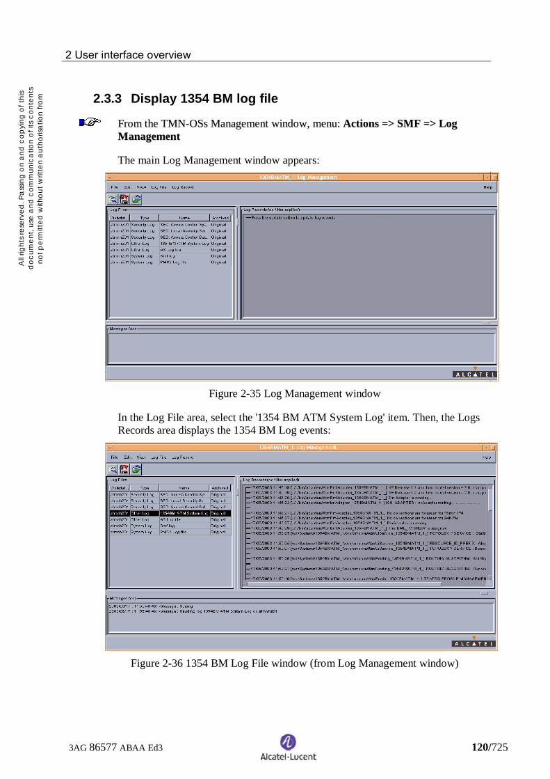
2 User interface overview
3AG 86577 ABAA Ed3 120/725
All r
ight
s res
erve
d. P
ass
ing
on
and
cop
ying
of t
his
doc
umen
t, us
e a
nd c
omm
unic
atio
n o
f its
con
tent
sno
t per
mitt
ed w
ithou
t writ
ten
aut
horis
atio
n fro
mA
lca
tel
2.3.3 Display 1354 BM log file
FFrroomm tthhee TTMMNN--OOSSss MMaannaaggeemmeenntt wwiinnddooww,, mmeennuu:: AAccttiioonnss ==>> SSMMFF ==>> LLooggMMaannaaggeemmeenntt
The main Log Management window appears:
Figure 2-35 Log Management window
In the Log File area, select the '1354 BM ATM System Log' item. Then, the LogsRecords area displays the 1354 BM Log events:
Figure 2-36 1354 BM Log File window (from Log Management window)

2 User interface overview
3AG 86577 ABAA Ed3 121/725
All r
ight
s res
erve
d. P
ass
ing
on
and
cop
ying
of t
his
doc
umen
t, us
e a
nd c
omm
unic
atio
n o
f its
con
tent
sno
t per
mitt
ed w
ithou
t writ
ten
aut
horis
atio
n fro
mA
lca
tel
AA ddyynnaammiicc 11335544 BBMM LLoogg FFiillee wwiinnddooww iiss aauuttoommaattiiccaallllyy llaauunncchheedd aanndd iissppoossiittiioonneedd iinn tthhee ttoopp ooff tthhee ssccrreeeenn,, oonn aa bblluuee ffoonntt,, oonn tthhee wwoorrkkssttaattiioonn//sseerrvveerr wwhheerree11335544 BBMM iiss llaauunncchheedd ((== ssttaarrtteedd ffrroomm tthhee PPrroocceessss MMoonniittoorriinngg CCoonnttrrooll ssooffttwwaarree))..
Figure 2-37 1354 BM Log File window

2 User interface overview
3AG 86577 ABAA Ed3 122/725
All r
ight
s res
erve
d. P
ass
ing
on
and
cop
ying
of t
his
doc
umen
t, us
e a
nd c
omm
unic
atio
n o
f its
con
tent
sno
t per
mitt
ed w
ithou
t writ
ten
aut
horis
atio
n fro
mA
lca
tel
2.4 Main view
The main view is the first window displayed at user interface launching.
Figure 2-38 Main view
The elements composing the main view are as follows:
− Title bar:− contains the product name:“1354 BM” and the system bar.
− Menu bar:− contains the titles from which pull down menus and cascading menus are
open. The menu bar displayed depends on the user profile.

2 User interface overview
3AG 86577 ABAA Ed3 123/725
All r
ight
s res
erve
d. P
ass
ing
on
and
cop
ying
of t
his
doc
umen
t, us
e a
nd c
omm
unic
atio
n o
f its
con
tent
sno
t per
mitt
ed w
ithou
t writ
ten
aut
horis
atio
n fro
mA
lca
tel
− General and contextual toolbars:− displays shortcut icons to access the main 1354 BM functions. For more
detailed information about the general toolbar, refer to § 2.5.3. Thecontextual toolbar depends on the desktop active window (refer to §2.5.3.1).
− Desktop:− displays all the other windows.
− ATM resources tree:− the tree area shows all the managed ATM resources in a hierarchical way.
For more information about the use of the tree, refer to § 2.4.1
− Status bar:− displays from left to right:
− the user’s login− the user’s profile− the connection status
Icon Meaning
It indicates that the GUI is no more connected to the applicationas long as the load of this is too important. The GUI is notrefreshed.
It indicates that the GUI is re-connecting to the application. Atthe end of this re-connection, the GUI is refreshed.
No iconIt indicates that the GUI is connected to the application. TheGUI is refreshed continuously.
− the title of the active window or the result of the last performed action− the Alcatel logo
The relative sizes of the tree and desktop areas may be modified by using the dragand drop mechanism on the vertical separation bar.

2 User interface overview
3AG 86577 ABAA Ed3 124/725
All r
ight
s res
erve
d. P
ass
ing
on
and
cop
ying
of t
his
doc
umen
t, us
e a
nd c
omm
unic
atio
n o
f its
con
tent
sno
t per
mitt
ed w
ithou
t writ
ten
aut
horis
atio
n fro
mA
lca
tel
2.4.1 Using the tree
Meaning of the symbolsThe symbols used in the tree area are as follows:Symbol Meaning
Closed directory
Open directory
Closed sub-network directoryOpen sub-network directoryNE operationalNE not operationalENE
Transmission path (IMA or not), hard / soft PVPC / PVCCIMA transmission path in failure
Elements of the list are not displayed
A directory represents a set of network items of the same type (sub-network, NE,ENE, transmission path, hard / soft PVPC / PVCC).
When everything is all right, all the symbols are as above, apart from the ENEsymbols that are always grey (not significant).
− For an NE, this means its alarm status is None (no alarm).− For a transmission path, a PVPC or a PVCC, this means its availability status is
Normal.− For a sub-network directory, this means all the elements it contains are all
right.
The symbol appears in the tree when there are too many elements to bedisplayed for the selected directory.By default, the symbol appears when the list to be displayed is greater than 40elements.Click on the symbol to open the associated list in the main view.If the list is lower than 40, all concerned element are listed in the tree.

2 User interface overview
3AG 86577 ABAA Ed3 125/725
All r
ight
s res
erve
d. P
ass
ing
on
and
cop
ying
of t
his
doc
umen
t, us
e a
nd c
omm
unic
atio
n o
f its
con
tent
sno
t per
mitt
ed w
ithou
t writ
ten
aut
horis
atio
n fro
mA
lca
tel
If a problem occurs, the green colour is replaced by another colour or by anothersymbol:
− For NE, the green square is replaced by a square with a red cross ( ).
− For transmission paths, PVPCs and PVCCs (if they are implemented orcommissioned), the green sphere is replaced by a symbol depending on theavailability status.
Availability status Symbol
Degraded
In failure
− For a sub-network directory, this depends on the elements it contains:− If the contained elements are NEs, the sphere takes the colour of the NE
whose alarm status is in the highest severity.− If the contained elements are transmission paths, PVPCs or PVCCs, the
sphere is replaced by the symbol of the element whose availability statusis the most serious.

2 User interface overview
3AG 86577 ABAA Ed3 126/725
All r
ight
s res
erve
d. P
ass
ing
on
and
cop
ying
of t
his
doc
umen
t, us
e a
nd c
omm
unic
atio
n o
f its
con
tent
sno
t per
mitt
ed w
ithou
t writ
ten
aut
horis
atio
n fro
mA
lca
tel
Tree structure
Figure 2-39 Tree structure
The first level directories (‘Construction’ and ‘Management’) are used for theclassification only. No action is available from them.
The ‘Construction’ directory contains the ‘Network Elements’ and ‘TransmissionPaths’ directories.
The ‘Network Elements’ is divided into sub-network directories that contain NEsand ENEs gathered in ‘NE’ and ‘ENE’ sub-directories.
The ‘Management’ directory contains the ‘Hard PVPC’, ‘Hard PVCC’, ‘SoftPVPC’ and ‘Soft PVCC’ directories. Each of them is divided into sub-networkdirectories that contain the corresponding entities.
Available actions

2 User interface overview
3AG 86577 ABAA Ed3 127/725
All r
ight
s res
erve
d. P
ass
ing
on
and
cop
ying
of t
his
doc
umen
t, us
e a
nd c
omm
unic
atio
n o
f its
con
tent
sno
t per
mitt
ed w
ithou
t writ
ten
aut
horis
atio
n fro
mA
lca
tel
To open/close a directory or a sub-directory, either double-click on its name orclick on the symbol located right on the left.
To perform actions from the tree, the user must use the contextual menu (refer to§ 2.5.4). The actions available in this contextual menu depend on the selectedsymbol.

2 User interface overview
3AG 86577 ABAA Ed3 128/725
All r
ight
s res
erve
d. P
ass
ing
on
and
cop
ying
of t
his
doc
umen
t, us
e a
nd c
omm
unic
atio
n o
f its
con
tent
sno
t per
mitt
ed w
ithou
t writ
ten
aut
horis
atio
n fro
mA
lca
tel
2.5 Accessing the functions
The functions of the 1354 BM user interface may be accessed:
− from the menus− from the icons− from the contextual menus− from the tree
2.5.1 From the menus
To access a function, click on the desired menu in the menu bar of the main view.
Example: to access the Transmission path creation function from the menus:
− Click on the Construction menu, then select the Transmission Paths option.The Transmission Path List window is displayed.
− Click again on the Construction menu, then select the Create option.
The Transmission Path Creation window is displayed.
AA ggrreeyyeedd mmeennuu ooppttiioonn mmeeaannss iitt iiss nnoott aavvaaiillaabbllee bbeeccaauussee iitt ccaannnnoott aappppllyy ttoo tthheeccuurrrreenntt sseelleeccttiioonn..
WWhheenn ppooiinnttiinngg aa mmeennuu oorr aa mmeennuu ooppttiioonn wwiitthh tthhee mmoouussee,, aa ssmmaallll bbooxx aappppeeaarrss ttoobbrriieeffllyy iinnddiiccaattee iittss mmeeaanniinngg oorr tthhee rreeaassoonn wwhhyy iitt iiss ggrreeyyeedd..

2 User interface overview
3AG 86577 ABAA Ed3 129/725
All r
ight
s res
erve
d. P
ass
ing
on
and
cop
ying
of t
his
doc
umen
t, us
e a
nd c
omm
unic
atio
n o
f its
con
tent
sno
t per
mitt
ed w
ithou
t writ
ten
aut
horis
atio
n fro
mA
lca
tel
2.5.2 From the icons
To access a function, click on the desired icon in the general or contextual toolbar.
Example: to access the Transmission path creation function from the icons:
− If a graphical view is displayed:
Click on the icon.
− If no graphical view are displayed:
Click on the icon.
Click on the icon.
The Transmission Path Creation window is displayed.
AA ggrreeyyeedd iiccoonn mmeeaannss iitt iiss nnoott aavvaaiillaabbllee bbeeccaauussee iitt ccaannnnoott aappppllyy ttoo tthhee ccuurrrreennttsseelleeccttiioonn..
WWhheenn ppooiinnttiinngg aann iiccoonn wwiitthh tthhee mmoouussee,, aa ssmmaallll bbooxx aappppeeaarrss ttoo bbrriieeffllyy iinnddiiccaattee iittssmmeeaanniinngg oorr tthhee rreeaassoonn wwhhyy iitt iiss ggrreeyyeedd..
In the main view, the icons are displayed in the toolbar.
The toolbar is divided into two parts:
− the general toolbar− the contextual toolbar

2 User interface overview
3AG 86577 ABAA Ed3 130/725
All r
ight
s res
erve
d. P
ass
ing
on
and
cop
ying
of t
his
doc
umen
t, us
e a
nd c
omm
unic
atio
n o
f its
con
tent
sno
t per
mitt
ed w
ithou
t writ
ten
aut
horis
atio
n fro
mA
lca
tel
2.5.3 General toolbar
The general toolbar is always available. It contains the following icons:Icon Equivalent menu option Displayed window
Main => Print Not available in release R7.
Reload all information showedto the operator (*)
View => Sub-network View => Hard =>Transmission Path Domain
Sub-network View –Hard Transmission Path Domain
- Root
Construction => Sub-networks Sub-network List
Construction => NE / ENENE / ENE List
(NE panel)
Construction => NE / ENENE / ENE List(ENE panel)
Construction => Transmission Path Transmission Path List
Management => Hard => VPC Hard VPC List
Management => Hard => VCC Hard VCC List
Management => Soft => VPCSoft VPC List
(Description panel)
Management => Soft => VCCSoft VCC List
(Description panel)
(*) Reload button:
Click on this button to reload all information showed to the operator.
In some cases, showed information is not relevant any more. The choice was toclose corresponding windows during the reload:
− the tree: it remains opened in the same state as before the reload except when aname of sub-network changed, the corresponding sub-network is closed if itwas opened.
− graphical views: if the name of the shown sub-network changed or do not existany more, the corresponding view is closed.
− lists: if the list does reference to an entity which does not exist any more orwhich changed name, it is closed (ex: the list of the legs of one PVC).
− properties window, bandwidth load window, extremities window: if the entitydoes not exist any more or if its name changed, the window is closed.

2 User interface overview
3AG 86577 ABAA Ed3 131/725
All r
ight
s res
erve
d. P
ass
ing
on
and
cop
ying
of t
his
doc
umen
t, us
e a
nd c
omm
unic
atio
n o
f its
con
tent
sno
t per
mitt
ed w
ithou
t writ
ten
aut
horis
atio
n fro
mA
lca
tel
2.5.3.1 Contextual toolbar
The icons available in the contextual toolbar depend on the current displayedwindow (graphical views or list windows) and the current selection.
Graphical viewsWhen a graphical view is active in the desktop of the main view, the contextualtoolbar may contain the following icons:
Icon Equivalent menu option Displayed window
View => Back (contextual)Sub-network view displayed
just before
View => Forward (contextual)Sub-network view displayed
just after
View => Up (contextual)
Sub-network view showing theparent sub-network
View => Root (contextual)
Sub-network view showing themain sub-network
Construction => Sub-networksthen Create (contextual) Sub-network Creation
Construction => NEthen Define (contextual) Available NE List
Construction => ENEthen Create (contextual) ENE Creation
Construction => Transmission Pathsthen Create (contextual) Transmission Path Creation
VViieeww ==>> OOppeenn SSuubb--nneettwwoorrkk ((ccoonntteexxttuuaall))oorr VViieeww ==>> SShhooww LLiinnkk LLiisstt ((ccoonntteexxttuuaall))
SSuubb--nneettwwoorrkk vviieewwsshhoowwiinngg tthhee ccoonntteenntt ooff aassuubb--nneettwwoorrkk oorr tthhee lliinnkkssccoonnttaaiinneedd iinn aa ggrroouuppeeddlliinnkk
VViieeww ==>> PPrrooppeerrttiieess ((ccoonntteexxttuuaall)) PPrrooppeerrttiieess
VViieeww ==>> DDeelleettee ((ccoonntteexxttuuaall)) DDiiaalloogg bbooxx ttoo ccoonnffiirrmm tthheeddeelleettiioonn
Other icons may be available but there are completely explicit.

2 User interface overview
3AG 86577 ABAA Ed3 132/725
All r
ight
s res
erve
d. P
ass
ing
on
and
cop
ying
of t
his
doc
umen
t, us
e a
nd c
omm
unic
atio
n o
f its
con
tent
sno
t per
mitt
ed w
ithou
t writ
ten
aut
horis
atio
n fro
mA
lca
tel
List windowsWhen a list window is active in the desktop of the main view, the contextualtoolbar contains only explicit icons.
Figure 2-40 Example of a contextual toolbar for a list window
2.5.4 From the contextual menu
The contextual menu allows the user to access all available operations applicableon the selection
A contextual menu can be displayed in a list window, a graphical view or the treearea of the main view.
Figure 2-41 Example of a contextual menu
To access a function, select one or several symbols in a graphical view or a line ina list window or an element in the tree area of the main view, then click with theright mouse button.
Example: to access the Transmission path creation function from a graphicalview by using the contextual menu:
− Select the NE origin and the NE / ENE destination.− Click on the right mouse button. The contextual menu is displayed.− Select the Create Transmission Path option.
The Transmission Path Creation window is displayed with User Label fields forOrigin and Destination already filled.

2 User interface overview
3AG 86577 ABAA Ed3 133/725
All r
ight
s res
erve
d. P
ass
ing
on
and
cop
ying
of t
his
doc
umen
t, us
e a
nd c
omm
unic
atio
n o
f its
con
tent
sno
t per
mitt
ed w
ithou
t writ
ten
aut
horis
atio
n fro
mA
lca
tel
If a contextual menu is also requested outside the current selection, the selection isaborted.
The contextual menu is updated according to the active window and the selection.
The same principle as for the menu bar is used to add, remove and shadow optionsin the contextual menu.
Those options are in the same state as their associated menu options in the menubar and their associated icons in the toolbars.
AA ggrreeyyeedd ccoonntteexxttuuaall mmeennuu ooppttiioonn mmeeaannss iitt iiss nnoott aavvaaiillaabbllee bbeeccaauussee iitt ccaannnnoott aappppllyyttoo tthhee ccuurrrreenntt sseelleeccttiioonn..
WWhheenn ppooiinnttiinngg aa ccoonntteexxttuuaall mmeennuu ooppttiioonn wwiitthh tthhee mmoouussee,, aa ssmmaallll bbooxx ((ccaalllleedd ttoooollttiipp)) aappppeeaarrss ttoo bbrriieeffllyy iinnddiiccaattee iittss mmeeaanniinngg oorr tthhee rreeaassoonn wwhhyy iitt iiss ggrreeyyeedd..
2.5.5 From the tree
From the tree, the user can access to all available operations applicable on theselected selection.
A contextual menu is displayed in the tree area when the user selects one symboland then clicks with the right mouse button.
2.5.6 Conventions
From here and in the whole user’s guide, the access to the functions of the1354 BM user interface will be given by using the menu bar.

2 User interface overview
3AG 86577 ABAA Ed3 134/725
All r
ight
s res
erve
d. P
ass
ing
on
and
cop
ying
of t
his
doc
umen
t, us
e a
nd c
omm
unic
atio
n o
f its
con
tent
sno
t per
mitt
ed w
ithou
t writ
ten
aut
horis
atio
n fro
mA
lca
tel
2.6 Window menu
Figure 2-42 Example of a Window menu
The Window menu allows the user to:
− arrange the windows open on the desktop (refer to § 2.6.1)− choose the active window (refer to § 2.6.2)
2.6.1 Arrange the windows
By using the Windows Arrangement item of the Window menu, the user accessesa sub-menu proposing five ways of displaying the current windows.
The figures below illustrate those arrangements.
TThhee wwiinnddoowwss tthhaatt ccaannnnoott bbee rreessiizzeedd kkeeeepp tthhee ssaammee ddiimmeennssiioonnss..

2 User interface overview
3AG 86577 ABAA Ed3 135/725
All r
ight
s res
erve
d. P
ass
ing
on
and
cop
ying
of t
his
doc
umen
t, us
e a
nd c
omm
unic
atio
n o
f its
con
tent
sno
t per
mitt
ed w
ithou
t writ
ten
aut
horis
atio
n fro
mA
lca
tel
Before arranging the windows
Figure 2-43 Example of a desktop before arranging the windows

2 User interface overview
3AG 86577 ABAA Ed3 136/725
All r
ight
s res
erve
d. P
ass
ing
on
and
cop
ying
of t
his
doc
umen
t, us
e a
nd c
omm
unic
atio
n o
f its
con
tent
sno
t per
mitt
ed w
ithou
t writ
ten
aut
horis
atio
n fro
mA
lca
tel
Horizontally tile arranging
Figure 2-44 Desktop with horizontal tile arrangement

2 User interface overview
3AG 86577 ABAA Ed3 137/725
All r
ight
s res
erve
d. P
ass
ing
on
and
cop
ying
of t
his
doc
umen
t, us
e a
nd c
omm
unic
atio
n o
f its
con
tent
sno
t per
mitt
ed w
ithou
t writ
ten
aut
horis
atio
n fro
mA
lca
tel
Mostly horizontally tile arranging
Figure 2-45 Desktop with mostly horizontal tile arrangement

2 User interface overview
3AG 86577 ABAA Ed3 138/725
All r
ight
s res
erve
d. P
ass
ing
on
and
cop
ying
of t
his
doc
umen
t, us
e a
nd c
omm
unic
atio
n o
f its
con
tent
sno
t per
mitt
ed w
ithou
t writ
ten
aut
horis
atio
n fro
mA
lca
tel
Vertically tile arranging
Figure 2-46 Desktop with vertical tile arrangement

2 User interface overview
3AG 86577 ABAA Ed3 139/725
All r
ight
s res
erve
d. P
ass
ing
on
and
cop
ying
of t
his
doc
umen
t, us
e a
nd c
omm
unic
atio
n o
f its
con
tent
sno
t per
mitt
ed w
ithou
t writ
ten
aut
horis
atio
n fro
mA
lca
tel
Mostly vertically tile arranging
Figure 2-47 Desktop with mostly vertical tile arrangement

2 User interface overview
3AG 86577 ABAA Ed3 140/725
All r
ight
s res
erve
d. P
ass
ing
on
and
cop
ying
of t
his
doc
umen
t, us
e a
nd c
omm
unic
atio
n o
f its
con
tent
sno
t per
mitt
ed w
ithou
t writ
ten
aut
horis
atio
n fro
mA
lca
tel
Cascade arranging
Figure 2-48 Desktop with cascade arrangement
TThhee ttiillee aarrrraannggeemmeenntt aapppplliieess oonnllyy ttoo nnoonn--iiccoonniiffiieedd wwiinnddoowwss wwhheenn tthhee ccaassccaaddeeaarrrraannggeemmeenntt ccoonncceerrnnss aallll tthhee wwiinnddoowwss..

2 User interface overview
3AG 86577 ABAA Ed3 141/725
All r
ight
s res
erve
d. P
ass
ing
on
and
cop
ying
of t
his
doc
umen
t, us
e a
nd c
omm
unic
atio
n o
f its
con
tent
sno
t per
mitt
ed w
ithou
t writ
ten
aut
horis
atio
n fro
mA
lca
tel
2.6.2 Choose the active window
The Window menu displays all the windows currently open on the desktop of themain view. A tick indicates the active window.
To activate another window, click on the corresponding title in the Window menu.

2 User interface overview
3AG 86577 ABAA Ed3 142/725
All r
ight
s res
erve
d. P
ass
ing
on
and
cop
ying
of t
his
doc
umen
t, us
e a
nd c
omm
unic
atio
n o
f its
con
tent
sno
t per
mitt
ed w
ithou
t writ
ten
aut
horis
atio
n fro
mA
lca
tel
2.7 Main menu
The Main menu allows the user to set its preferences and exit from the userinterface.
It includes the following options:
− Print… : not yet implemented in 1354 BM R7.− Reload : to resynchronize all opened elements.− Options : to change the user preferences.
The options are as follows:− Show / Hide Toolbar: to make visible or not the toolbars− Show / Hide Tree: to make visible or not the tree area
− Close : to close the current window.− Exit : to exit from the 1354 BM user interface.

2 User interface overview
3AG 86577 ABAA Ed3 143/725
All r
ight
s res
erve
d. P
ass
ing
on
and
cop
ying
of t
his
doc
umen
t, us
e a
nd c
omm
unic
atio
n o
f its
con
tent
sno
t per
mitt
ed w
ithou
t writ
ten
aut
horis
atio
n fro
mA
lca
tel
2.8 View menu
The View menu allows the user to access the graphical views and navigate withinthem.
It includes the following options:
− Sub-network view: to display the sub-networks from a geographical point ofview
− Global view: to display the global network from a hierarchical point of view
For each type of view, two options are available:
− Hard: to display hard domain views− Soft: to display soft domain views
For each domain, three possibilities:
− Transmission Path Domain: to perform actions on sub-networks, NEs /ENEs (isolated or as extremities of transmission paths) and transmissionpaths.
− VP Domain: to perform actions on sub-networks, NEs / ENEs (asextremities of transmission paths) and PVPC.
− VC Domain: to perform actions on sub-networks, NEs / ENEs (asextremities of PVPCs), and PVCCs.
When a sub-network view is active, the following options are added:
− Back: to display the view shown before the current view.− Forward: to display the view shown after the current view.− Up: to display the parent sub-network view of the current sub-network view.− Root: to display the root sub-network view.− Zoom in: to zoom in the current sub-network view (CTRL+Z).− Zoom out: to stop zoom in the current sub-network view (CTRL+U).− Select Background: to select the map to be used as background for the current
sub-network view (refer to § 2.8.1).− Save: to memorize the last map used as a background in all views (refer to §
2.8.2).
Other menu options may be added depending on the graphical view and/or theselected symbol type: Sub-network, NE, ENE, Transmission Path (refer to § 3).
The sub-network views and the global views use symbols for representing theelements of the network (refer to § 2.8.3).
The selection rules specific to the graphical views are described in § 2.8.4.

2 User interface overview
3AG 86577 ABAA Ed3 144/725
All r
ight
s res
erve
d. P
ass
ing
on
and
cop
ying
of t
his
doc
umen
t, us
e a
nd c
omm
unic
atio
n o
f its
con
tent
sno
t per
mitt
ed w
ithou
t writ
ten
aut
horis
atio
n fro
mA
lca
tel
2.8.1 Select a background map
This option is available for a sub-network or global view in transmission pathdomain. It consists in associating an image as a background of the view.
FFrroomm tthhee ssuubb--nneettwwoorrkk oorr gglloobbaall vviieeww,, mmeennuu:: VViieeww ==>> SSeelleecctt BBaacckkggrroouunndd
Figure 2-49 Select a New Map for Background window
To choose a map:
− Click on a map in the list. The map appears in the right part of the window.− When the map is chosen, click on Ok.
The selected map is displayed in the background of the current view.
To memorise that new background map, use the Save option (refer to § 2.8.2) orquit the active graphical window.

2 User interface overview
3AG 86577 ABAA Ed3 145/725
All r
ight
s res
erve
d. P
ass
ing
on
and
cop
ying
of t
his
doc
umen
t, us
e a
nd c
omm
unic
atio
n o
f its
con
tent
sno
t per
mitt
ed w
ithou
t writ
ten
aut
horis
atio
n fro
mA
lca
tel
2.8.2 Save a sub-network or global view
This option is only available in the transmission path domain.
It consists in saving all views with its last selected background map and theposition of each symbol on it.
FFrroomm tthhee ssuubb--nneettwwoorrkk oorr gglloobbaall vviieeww,, mmeennuu:: VViieeww ==>> SSaavvee
TThhee bbaacckkggrroouunndd mmaapp aanndd tthhee ppoossiittiioonn ooff eeaacchh ssyymmbbooll aarree aauuttoommaattiiccaallllyy ssaavveeddwwhheenn::
− the application is closed− the sub-network or global view is closed− the operator navigates inside the network

2 User interface overview
3AG 86577 ABAA Ed3 146/725
All r
ight
s res
erve
d. P
ass
ing
on
and
cop
ying
of t
his
doc
umen
t, us
e a
nd c
omm
unic
atio
n o
f its
con
tent
sno
t per
mitt
ed w
ithou
t writ
ten
aut
horis
atio
n fro
mA
lca
tel
2.8.3 Network representation
The symbols used for representing the network are as follows:
SSyymmbbooll MMeeaanniinngg
SSuubb--nneettwwoorrkk
NNEE ooppeerraattiioonnaall
EENNEE
TTrraannssmmiissssiioonn PPaatthh nnoott ccoonnffiigguurreedd ((**))
HHaarrdd LLiinnkk ((ttrraannssmmiissssiioonn ppaatthh,, PPVVPPCC oorr PPVVCCCC)) ((**))
SSoofftt LLiinnkk ((ttrraannssmmiissssiioonn ppaatthh,, PPVVPPCC oorr PPVVCCCC)) ((**))
GGrroouuppeedd lliinnkkss
OOffff--ppaaggee ccoonnnneeccttoorr.. OOnnllyy uusseedd iinn ssuubb--nneettwwoorrkk vviieewwsswwhheenn aa lliinnkk eexxttrreemmiittyy bbeelloonnggss ttoo aannootthheerr ssuubb--nneettwwoorrkkvviieeww
NNEE wwiitthh LLAACC ssttaattee eeqquuaall ttoo GGrraanntteedd
NNEE wwiitthh LLAACC ssttaattee eeqquuaall ttoo PPoosstt--ggrraanntteedd
(*) The colours are configurable (refer to the Administration Guide)

2 User interface overview
3AG 86577 ABAA Ed3 147/725
All r
ight
s res
erve
d. P
ass
ing
on
and
cop
ying
of t
his
doc
umen
t, us
e a
nd c
omm
unic
atio
n o
f its
con
tent
sno
t per
mitt
ed w
ithou
t writ
ten
aut
horis
atio
n fro
mA
lca
tel
When all is all right, the sub-network, NE and off-page connector symbols are asabove (surrounded in green).
− For an NE, this means its alarm status is None (no alarm).− For an off-page connector, this means the alarm status of the NE it represents is
None (no alarm).− For a sub-network, this means all the elements it contains are all right.
If a problem occurs, the green colour that surrounds the symbol is replaced byanother colour, and/or another small symbol may be added.
− For NEs and off-page connectors, the colour depends on the NE severity alarm(refer to chapter 9).
− For links (if they are commissioned), another small symbol depending on theavailability status is added to the link symbol.
− For a sub-network, this depends on the states of the elements it contains.− The surrounder of the symbol takes the colour of the NE whose alarm
status is in the highest severity.− If the availability status of at least one link contained in the sub-network is
not normal, the small symbol present on the link whose availability statusis the most serious is added to the sub-network symbol.
The table below shows some examples of symbols representing faulty elements.
Symbol Meaning
NE not operational
Link whose availability status is In failure
Grouped link containing at least one link whose availabilitystatus is Degraded
Sub-network whose global alarm status is Major (filled withorange) and containing at least one link whose availability
status is In failure

2 User interface overview
3AG 86577 ABAA Ed3 148/725
All r
ight
s res
erve
d. P
ass
ing
on
and
cop
ying
of t
his
doc
umen
t, us
e a
nd c
omm
unic
atio
n o
f its
con
tent
sno
t per
mitt
ed w
ithou
t writ
ten
aut
horis
atio
n fro
mA
lca
tel
2.8.4 Selection rules in a graphical view
In addition to those described in § 2.1.4, the graphical views have their ownselection rules.
Double-clickThe double–click on each symbol is available and allows the user to visualise aspecific view or open a specific window according to the selected symbol.
− Sub-network: Display, in the current window, the content of the sub-network− Off-page connector: Display, in the current window, the content of the sub-
network which contains the equipment represented by the off-page connector.− NE/ENE: Open the NE/ENE properties window− Link: Open the link extremities window− Grouped link: Open the link view window
Multi-selectionTo select several symbols, press the Shift key while left clicking on the symbols.
A multi-selection of symbols can be moved (by using the drag and dropmechanism) as a single symbol.
2.8.5 Sub-network views
The sub-network views allow the user to visualise a specific sub-network from ageographical point of view.
There are three domains:
− Transmission path− Virtual Path (VP)− Virtual Channel (VC)

2 User interface overview
3AG 86577 ABAA Ed3 149/725
All r
ight
s res
erve
d. P
ass
ing
on
and
cop
ying
of t
his
doc
umen
t, us
e a
nd c
omm
unic
atio
n o
f its
con
tent
sno
t per
mitt
ed w
ithou
t writ
ten
aut
horis
atio
n fro
mA
lca
tel
2.8.5.1 Sub-network views in transmission path domain
The sub-network views in transmission path domain show the transmission pathsexisting between NEs / ENEs that belong or not to sub-networks. At least oneextremity of the transmission path must be in the sub-network.
FFrroomm tthhee MMaaiinn vviieeww,, mmeennuu:: VViieeww ==>> SSuubb--nneettwwoorrkk VViieeww ==>> HHaarrdd oorr SSoofftt ==>>TTrraannssmmiissssiioonn PPaatthh DDoommaaiinn
Figure 2-50 Transmission path domain sub-network view

2 User interface overview
3AG 86577 ABAA Ed3 150/725
All r
ight
s res
erve
d. P
ass
ing
on
and
cop
ying
of t
his
doc
umen
t, us
e a
nd c
omm
unic
atio
n o
f its
con
tent
sno
t per
mitt
ed w
ithou
t writ
ten
aut
horis
atio
n fro
mA
lca
tel
The first displayed sub-network view corresponds to the root sub-network. It maycontain only sub-networks, ENEs and transmission paths between them.
From a sub-network view in transmission path domain, you can:
− create sub-networks, NEs (except in sub-network Root), ENEs andtransmission paths
− select a symbol and perform actions from it (refer to chapter 3 and 4)− open a sub-network (refer to § 2.8.5.4)− open a grouped link (refer to § 2.8.5.5)− navigate through an off-page connector (refer to § 2.8.5.6)− select a background map (refer to § 2.8.1)− save a sub-network or global view (refer to § 2.8.2)

2 User interface overview
3AG 86577 ABAA Ed3 151/725
All r
ight
s res
erve
d. P
ass
ing
on
and
cop
ying
of t
his
doc
umen
t, us
e a
nd c
omm
unic
atio
n o
f its
con
tent
sno
t per
mitt
ed w
ithou
t writ
ten
aut
horis
atio
n fro
mA
lca
tel
2.8.5.2 Sub-network views in VP domain
The sub-network views in VP domain show the PVPCs existing between NEs /ENEs that belong or not to sub-networks.
FFrroomm tthhee MMaaiinn vviieeww,, mmeennuu:: VViieeww ==>> SSuubb--nneettwwoorrkk VViieeww ==>> HHaarrdd oorr SSoofftt ==>>VVPP DDoommaaiinn
Figure 2-51 VP domain sub-network view

2 User interface overview
3AG 86577 ABAA Ed3 152/725
All r
ight
s res
erve
d. P
ass
ing
on
and
cop
ying
of t
his
doc
umen
t, us
e a
nd c
omm
unic
atio
n o
f its
con
tent
sno
t per
mitt
ed w
ithou
t writ
ten
aut
horis
atio
n fro
mA
lca
tel
The first displayed sub-network view corresponds to the root sub-network. It maycontain only sub-networks, ENEs and PVPCs between them.
From a sub-network view in VP domain, you can:
− define PVPCs− select a symbol and perform actions from it (refer to chapter 3)− open a sub-network (refer to § 2.8.5.4)− open a grouped link (refer to § 2.8.5.5)− navigate through an off-page connector (refer to § 2.8.5.6)

2 User interface overview
3AG 86577 ABAA Ed3 153/725
All r
ight
s res
erve
d. P
ass
ing
on
and
cop
ying
of t
his
doc
umen
t, us
e a
nd c
omm
unic
atio
n o
f its
con
tent
sno
t per
mitt
ed w
ithou
t writ
ten
aut
horis
atio
n fro
mA
lca
tel
2.8.5.3 Sub-network views in VC domain
The sub-network views in VC domain show the PVCCs existing between NEs /ENEs that belong or not to sub-networks.
FFrroomm tthhee MMaaiinn vviieeww,, mmeennuu:: VViieeww ==>> SSuubb--nneettwwoorrkk VViieeww ==>> HHaarrdd oorr SSoofftt ==>>VVCC DDoommaaiinn
Figure 2-52 VC domain sub-network view

2 User interface overview
3AG 86577 ABAA Ed3 154/725
All r
ight
s res
erve
d. P
ass
ing
on
and
cop
ying
of t
his
doc
umen
t, us
e a
nd c
omm
unic
atio
n o
f its
con
tent
sno
t per
mitt
ed w
ithou
t writ
ten
aut
horis
atio
n fro
mA
lca
tel
The first displayed sub-network view corresponds to the root sub-network. It maycontain only sub-networks, ENEs and PVCCs between them.
From a sub-network view in VC domain, you can:
− define PVCCs− select a symbol and perform actions from it (refer to chapter 3)− open a sub-network (refer to § 2.8.5.4)− open a grouped link (refer to § 2.8.5.5)− navigate through an off-page connector (refer to § 2.8.5.6)

2 User interface overview
3AG 86577 ABAA Ed3 155/725
All r
ight
s res
erve
d. P
ass
ing
on
and
cop
ying
of t
his
doc
umen
t, us
e a
nd c
omm
unic
atio
n o
f its
con
tent
sno
t per
mitt
ed w
ithou
t writ
ten
aut
horis
atio
n fro
mA
lca
tel
2.8.5.4 Open a sub-network
A sub-network may contain NEs, ENEs and/or other sub-networks.
FFrroomm aa SSuubb--nneettwwoorrkk VViieeww,, sseelleecctt aa ssuubb--nneettwwoorrkk ==>> VViieeww ==>> OOppeenn SSuubb--nneettwwoorrkk
DDoouubbllee--cclliicckkiinngg oonn tthhee ssuubb--nneettwwoorrkk ssyymmbbooll hhaass tthhee ssaammee eeffffeecctt..
A new sub-network view replaces the current one and the map disappears.
Figure 2-53 Example of a sub-network view showing the content of a sub-network

2 User interface overview
3AG 86577 ABAA Ed3 156/725
All r
ight
s res
erve
d. P
ass
ing
on
and
cop
ying
of t
his
doc
umen
t, us
e a
nd c
omm
unic
atio
n o
f its
con
tent
sno
t per
mitt
ed w
ithou
t writ
ten
aut
horis
atio
n fro
mA
lca
tel
2.8.5.5 Open a grouped link
A grouped link may contain several transmission paths or several PVPCs orseveral PVCCs.
FFrroomm aa SSuubb--nneettwwoorrkk VViieeww,, sseelleecctt aa ggrroouuppeedd lliinnkk ==>> VViieeww ==>> SShhooww LLiinnkkss LLiisstt
DDoouubbllee--cclliicckkiinngg oonn tthhee ggrroouuppeedd lliinnkk ssyymmbbooll hhaass tthhee ssaammee eeffffeecctt..
Figure 2-54 Example of a link view
In a link view - Hard Transmission Path Domain, you can select a NE to have itsproperties or a transmission path then:
− delete it− display its extremities− display its properties− configure it− display its bandwidth load− lock/unlock a transmission path− partition a transmission path− display the fault localization list (if an alarm impacts the selected transmission
path)(refer to chapter 3 to have details about these commands).

2 User interface overview
3AG 86577 ABAA Ed3 157/725
All r
ight
s res
erve
d. P
ass
ing
on
and
cop
ying
of t
his
doc
umen
t, us
e a
nd c
omm
unic
atio
n o
f its
con
tent
sno
t per
mitt
ed w
ithou
t writ
ten
aut
horis
atio
n fro
mA
lca
tel
2.8.5.6 Navigate through an off-page connector
An off-page connector symbol represents a NE that belongs to another sub-network. It can be used to navigate from a sub-network to another one.
FFrroomm aa SSuubb--nneettwwoorrkk VViieeww,, sseelleecctt aann ooffff--ppaaggee ccoonnnneeccttoorr ==>> VViieeww ==>> SShhooww RReeaallEExxttrreemmiittyy
DDoouubbllee--cclliicckkiinngg oonn tthhee ooffff--ppaaggee ccoonnnneeccttoorr ssyymmbbooll hhaass tthhee ssaammee eeffffeecctt..
The view of the sub-network containing the other extremity of the off-pageconnector replaces the current sub-network view.

2 User interface overview
3AG 86577 ABAA Ed3 158/725
All r
ight
s res
erve
d. P
ass
ing
on
and
cop
ying
of t
his
doc
umen
t, us
e a
nd c
omm
unic
atio
n o
f its
con
tent
sno
t per
mitt
ed w
ithou
t writ
ten
aut
horis
atio
n fro
mA
lca
tel
2.8.6 Global views
The global views allow the user to visualise the network in its totality. Here, thereare no geographical aspects but hierarchical aspects.
There are three domains:
− Transmission Path− Virtual Path (VP)− Virtual Channel (VC)
Any sub-network displayed in a global view can be opened / closed in order toknow what it contains (refer to § 2.8.6.4).

2 User interface overview
3AG 86577 ABAA Ed3 159/725
All r
ight
s res
erve
d. P
ass
ing
on
and
cop
ying
of t
his
doc
umen
t, us
e a
nd c
omm
unic
atio
n o
f its
con
tent
sno
t per
mitt
ed w
ithou
t writ
ten
aut
horis
atio
n fro
mA
lca
tel
2.8.6.1 Global views in transmission path domain
The global views in transmission path domain show the transmission pathsexisting between NEs / ENEs that belong or not to sub-networks.
FFrroomm tthhee MMaaiinn vviieeww,, mmeennuu:: VViieeww ==>> GGlloobbaall VViieeww ==>> HHaarrdd oorr SSoofftt ==>>TTrraannssmmiissssiioonn PPaatthh DDoommaaiinn
Figure 2-55 Transmission path domain global view
The global view displayed by default may only contain sub-networks, ENEs andtransmission paths between them.
From this view, you can:
− create sub-networks, NEs (except in sub-network Root), ENEs andtransmission paths
− select a symbol and perform actions from it (refer to chapter 3)− expand a sub-network (refer to § 2.8.6.4)− select a background map (refer to § 2.8.1)− save a sub-network or global view (refer to § 2.8.2)

2 User interface overview
3AG 86577 ABAA Ed3 160/725
All r
ight
s res
erve
d. P
ass
ing
on
and
cop
ying
of t
his
doc
umen
t, us
e a
nd c
omm
unic
atio
n o
f its
con
tent
sno
t per
mitt
ed w
ithou
t writ
ten
aut
horis
atio
n fro
mA
lca
tel
2.8.6.2 Global views in VP domain
The global views in VP domain show the PVPCs existing between NEs / ENEsthat belong or not to sub-networks.
FFrroomm tthhee MMaaiinn vviieeww,, mmeennuu:: VViieeww ==>> GGlloobbaall VViieeww ==>> HHaarrdd oorr SSoofftt ==>> VVPPDDoommaaiinn
Figure 2-56 VP domain global view
The global view displayed by default may only contain sub-networks, ENEs andPVPCs between them.
From this view, you can:
− define PVPCs− select a symbol and perform actions from it (refer to chapter 3)− open a sub-network (refer to § 2.8.6.4)

2 User interface overview
3AG 86577 ABAA Ed3 161/725
All r
ight
s res
erve
d. P
ass
ing
on
and
cop
ying
of t
his
doc
umen
t, us
e a
nd c
omm
unic
atio
n o
f its
con
tent
sno
t per
mitt
ed w
ithou
t writ
ten
aut
horis
atio
n fro
mA
lca
tel
2.8.6.3 Global views in VC domain
The global views in VC domain show the PVCCs existing between NEs / ENEsthat belong or not to sub-networks.
FFrroomm tthhee MMaaiinn vviieeww,, mmeennuu:: VViieeww ==>> GGlloobbaall VViieeww ==>> HHaarrdd oorr SSoofftt ==>> VVCCDDoommaaiinn
Figure 2-57 VC domain global view
The global view displayed by default may only contain sub-networks, ENEs andPVCCs between them.
From this view, you can:
− define PVCCs− select a symbol and perform actions from it (refer to chapter 3)− open a sub-network (refer to § 2.8.6.4)

2 User interface overview
3AG 86577 ABAA Ed3 162/725
All r
ight
s res
erve
d. P
ass
ing
on
and
cop
ying
of t
his
doc
umen
t, us
e a
nd c
omm
unic
atio
n o
f its
con
tent
sno
t per
mitt
ed w
ithou
t writ
ten
aut
horis
atio
n fro
mA
lca
tel
2.8.6.4 Open / close a sub-network
This option applies only on a sub-network symbol. It allows the user to knowwhat a sub-network contains.
Both following figures illustrate the open / close mechanism applied to a sub-network as example.
Figure 2-58 Example of a closed sub-network

2 User interface overview
3AG 86577 ABAA Ed3 163/725
All r
ight
s res
erve
d. P
ass
ing
on
and
cop
ying
of t
his
doc
umen
t, us
e a
nd c
omm
unic
atio
n o
f its
con
tent
sno
t per
mitt
ed w
ithou
t writ
ten
aut
horis
atio
n fro
mA
lca
tel
Open a sub-network
FFrroomm aa GGlloobbaall VViieeww,, sseelleecctt aa ssuubb--nneettwwoorrkk ==>> VViieeww ==>> OOppeenn SSuubb--nneettwwoorrkk
The global view becomes as follows:
Figure 2-59 Example of an opened sub-network
Close a sub-network
FFrroomm tthhee GGlloobbaall VViieeww,, sseelleecctt aa NNEE,, aann EENNEE oorr aa lliinnkk bbeelloonnggiinngg ttoo aa ssuubb--nneettwwoorrkk==>> VViieeww ==>> CClloossee SSuubb--nneettwwoorrkk
The global view becomes as before again.

2 User interface overview
3AG 86577 ABAA Ed3 164/725
All r
ight
s res
erve
d. P
ass
ing
on
and
cop
ying
of t
his
doc
umen
t, us
e a
nd c
omm
unic
atio
n o
f its
con
tent
sno
t per
mitt
ed w
ithou
t writ
ten
aut
horis
atio
n fro
mA
lca
tel
2.9 Help menu
The help is an important aspect of the 1354 BM user interface. By using thisfunctionality the user can get information on actions he/she is carrying out.
The help is based on the world web technologies. The topics are written in html.A browser is used to navigate through the html pages.
Access to the 1354 BM help is possible in two different ways: permanent accessesand access when using the 1354 BM.
− Permanent access: any time the user needs information, he/she can start thebrowser and access the 1354 BM. It is not necessary to have a 1354 BMproduct running, but just a browser:− Click on the TMN-OSs Management System icon. Then the TMN-OSs
Management main view is displayed− From the Actions menu, select the On Line Help command.
− Access when using the 1354 BM: once launched, the 1354 BM provides theuser with:− a general help (refer to § 2.9.1)− a contextual help (refer to § 2.9.2)

2 User interface overview
3AG 86577 ABAA Ed3 165/725
All r
ight
s res
erve
d. P
ass
ing
on
and
cop
ying
of t
his
doc
umen
t, us
e a
nd c
omm
unic
atio
n o
f its
con
tent
sno
t per
mitt
ed w
ithou
t writ
ten
aut
horis
atio
n fro
mA
lca
tel
2.9.1 General help
To access the general help, use the Help menu in the menu bar of the main view.
The Help menu options are as follows:
− Contents and Index: displays the home page of the on line help
Figure 2-60 Home page of the on line help

2 User interface overview
3AG 86577 ABAA Ed3 166/725
All r
ight
s res
erve
d. P
ass
ing
on
and
cop
ying
of t
his
doc
umen
t, us
e a
nd c
omm
unic
atio
n o
f its
con
tent
sno
t per
mitt
ed w
ithou
t writ
ten
aut
horis
atio
n fro
mA
lca
tel
− Search for Help on …: displays the search page of the on line help
Figure 2-61 Search page of the on line help

2 User interface overview
3AG 86577 ABAA Ed3 167/725
All r
ight
s res
erve
d. P
ass
ing
on
and
cop
ying
of t
his
doc
umen
t, us
e a
nd c
omm
unic
atio
n o
f its
con
tent
sno
t per
mitt
ed w
ithou
t writ
ten
aut
horis
atio
n fro
mA
lca
tel
− Glossary: displays the user interface glossary
Figure 2-62 Glossary page of the on line help
− Alcatel on the Web: launchs the Internet browser to the www.alcatel.comaddress
− On window: launchs the Internet browser and provides the help concerning theselected window.

2 User interface overview
3AG 86577 ABAA Ed3 168/725
All r
ight
s res
erve
d. P
ass
ing
on
and
cop
ying
of t
his
doc
umen
t, us
e a
nd c
omm
unic
atio
n o
f its
con
tent
sno
t per
mitt
ed w
ithou
t writ
ten
aut
horis
atio
n fro
mA
lca
tel
− About 1354 BM: displays copyright and version information about 1354 BM
Figure 2-63 Example of an About 1354 BM dialog box
2.9.2 Contextual help
To access the contextual help from any 1354 BM window, there are twopossibilities:
− Press the F1 key− Use the help menu in the menu bar of the main view and select the “on
window” option.
The on line help opens at the page corresponding to the current active window.

2 User interface overview
3AG 86577 ABAA Ed3 169/725
All r
ight
s res
erve
d. P
ass
ing
on
and
cop
ying
of t
his
doc
umen
t, us
e a
nd c
omm
unic
atio
n o
f its
con
tent
sno
t per
mitt
ed w
ithou
t writ
ten
aut
horis
atio
n fro
mA
lca
tel

3 Network construction
3AG 86577 ABAA Ed3 170/725
All r
ight
s res
erve
d. P
ass
ing
on a
nd c
opyi
ng o
f thi
sd
ocum
ent,
use
and
com
mun
ica
tion
of i
ts c
onte
nts
not p
erm
itted
with
out w
ritte
n a
utho
risa
tion
from
Alc
ate
l
3 Network construction
The network construction consists in:
3.1 Managing sub-networks
3.2 Managing NEs
3.3 Managing ENEs
3.4 Managing transmission paths

3 Network construction
3AG 86577 ABAA Ed3 171/725
All r
ight
s res
erve
d. P
ass
ing
on a
nd c
opyi
ng o
f thi
sd
ocum
ent,
use
and
com
mun
ica
tion
of i
ts c
onte
nts
not p
erm
itted
with
out w
ritte
n a
utho
risa
tion
from
Alc
ate
l
The network construction chain gives the order in which the construction must beperformed.
Creating sub-networks
Defining NEs
Creating transmission paths
Creating ENEs
Figure 3-1 Network construction chain

3 Network construction
3AG 86577 ABAA Ed3 172/725
All r
ight
s res
erve
d. P
ass
ing
on a
nd c
opyi
ng o
f thi
sd
ocum
ent,
use
and
com
mun
ica
tion
of i
ts c
onte
nts
not p
erm
itted
with
out w
ritte
n a
utho
risa
tion
from
Alc
ate
l
3.1 Managing sub-networks
In order to be managed more easily the network is structured into sub-networks.
Each sub-network is linked up with a sub-network or the main network.According to its level, a sub-network may contain other sub-networks, NEs orENEs.
The sub-network management, part of the network construction, consists in:
− performing actions such as creating / modifying / deleting sub-networks− displaying sub-network information such as sub-network list, propertiesSeveral rules must be respected:
− the main network is created by the 1354 BM (root by default namely if it wasnot modified during the installation step)
− the main network is only composed of sub-networks and ENEsThe sub-network management chain gives the order in which the available actionsmay be performed.
Create sub-network
Delete sub-network
Modify sub-network
Figure 3-2 Sub-network management chain
For managing sub-networks, you can:
display the sub-network list, refer to § 3.1.1

3 Network construction
3AG 86577 ABAA Ed3 173/725
All r
ight
s res
erve
d. P
ass
ing
on a
nd c
opyi
ng o
f thi
sd
ocum
ent,
use
and
com
mun
ica
tion
of i
ts c
onte
nts
not p
erm
itted
with
out w
ritte
n a
utho
risa
tion
from
Alc
ate
l
3.1.1 Display the sub-network list
The Sub-network List window presents all the sub-networks and their attributes.
FFrroomm tthhee MMaaiinn vviieeww,, mmeennuu:: CCoonnssttrruuccttiioonn ==>> SSuubb--nneettwwoorrkkss
Figure 3-3 Sub-network List window
The attributes displayed for each sub-network are:
− User Label− Parent Sub-network User Label− CommentFor column description, refer to chapter 9.
SSoorrtt bbyy cclliicckkiinngg oonn tthhee ccoolluummnn hheeaaddeerr tthhaatt yyoouu wwaanntt ttoo ssoorrtt..
The sorting criteria are as follows:
− User Label− Parent Sub-network User Label
Filter by clicking on Search in the toolbar.
TThhee sseeaarrcchh ffuunnccttiioonn iiss aavvaaiillaabbllee oonnllyy wwiitthh nnoo sseelleeccttiioonn iinn tthhee lliisstt.. FFoorr ddee--sseelleeccttiioonnccoommmmaanndd,, rreeffeerr ttoo §§ 22..11..44..

3 Network construction
3AG 86577 ABAA Ed3 174/725
All r
ight
s res
erve
d. P
ass
ing
on a
nd c
opyi
ng o
f thi
sd
ocum
ent,
use
and
com
mun
ica
tion
of i
ts c
onte
nts
not p
erm
itted
with
out w
ritte
n a
utho
risa
tion
from
Alc
ate
l
Figure 3-4 Sub-network Search window
Enter the chosen filtering criteria then click on Ok.
FFrroomm tthhee SSuubb--nneettwwoorrkk LLiisstt wwiinnddooww,, yyoouu ccaann::
create a sub-network, refer to § 3.1.2 (if no sub-network selected)
create a sub-network inside the selected sub-network, refer to § 3.1.2
modify a sub-network, refer to § 3.1.3
delete a sub-network, refer to § 3.1.4
get the sub-network properties, refer to § 3.1.5

3 Network construction
3AG 86577 ABAA Ed3 175/725
All r
ight
s res
erve
d. P
ass
ing
on a
nd c
opyi
ng o
f thi
sd
ocum
ent,
use
and
com
mun
ica
tion
of i
ts c
onte
nts
not p
erm
itted
with
out w
ritte
n a
utho
risa
tion
from
Alc
ate
l
3.1.2 Create a sub-network
This function consists in adding a sub-network to the main network or to anothersub-network. It is also possible to create a sub-network inside another one.
-- TThhee ppaarreenntt ssuubb--nneettwwoorrkk mmuusstt bbee pprreevviioouussllyy ccrreeaatteedd..
-- TThhee mmaaxxiimmuumm nnuummbbeerr ooff ssuubb--nneettwwoorrkk lleevveellss mmuusstt nnoott bbee rreeaacchheedd..
-- TThhee mmaaxxiimmuumm nnuummbbeerr ooff ssuubb--nneettwwoorrkkss mmuusstt nnoott bbee rreeaacchheedd..
-- TThhee UUsseerr LLaabbeell mmuusstt bbee ddiiffffeerreenntt aass oonnee wwhhiicchh iiss aallrreeaaddyy uusseedd bbyy aannootthheerr ssuubb--nneettwwoorrkk oorr oonnee wwhhiicchh iiss rreesseerrvveedd ffoorr tthhee mmaaiinn nneettwwoorrkk..
FFrroomm tthhee MMaaiinn vviieeww,, mmeennuu:: CCoonnssttrruuccttiioonn ==>> SSuubb--nneettwwoorrkkss ==>> CCrreeaattee
TThhiiss ffuunnccttiioonn iiss aavvaaiillaabbllee oonnllyy wwiitthh nnoo sseelleeccttiioonn iinn tthhee lliisstt.. FFoorr ddee--sseelleeccttiioonnccoommmmaanndd,, rreeffeerr ttoo §§ 22..11..44..
FFrroomm aa sseelleecctteedd ssuubb--nneettwwoorrkk ((iinn hhaarrdd oorr ssoofftt ttrraannssmmiissssiioonn ppaatthh ddoommaaiinn ggrraapphhiiccaallvviieewwss,, ssuubb--nneettwwoorrkk lliisstt oorr iinn tthhee ttrreeee)) tthhee ccoommmmaanndd bbeeccoommeess CCrreeaattee iinnssiiddee..
Figure 3-5 Sub-network Creation window
To create a sub-network:
− Enter an User Label.− Choose the Parent sub-network User Label by using the sensitive help. If a
sub-network has been previously selected in a graphical view or in the tree areaof the main view, this field is automatically filled.
− Enter a Comment (optional).− Click on Ok.

3 Network construction
3AG 86577 ABAA Ed3 176/725
All r
ight
s res
erve
d. P
ass
ing
on a
nd c
opyi
ng o
f thi
sd
ocum
ent,
use
and
com
mun
ica
tion
of i
ts c
onte
nts
not p
erm
itted
with
out w
ritte
n a
utho
risa
tion
from
Alc
ate
l
The sub-network is created.
The tree area, the sub-network list and the opened graphical views are updated.
The sub-networks are displayed in bold types in the tree area.
It is then possible to define ATM NEs, ENEs or create a sub-network in this sub-network.

3 Network construction
3AG 86577 ABAA Ed3 177/725
All r
ight
s res
erve
d. P
ass
ing
on a
nd c
opyi
ng o
f thi
sd
ocum
ent,
use
and
com
mun
ica
tion
of i
ts c
onte
nts
not p
erm
itted
with
out w
ritte
n a
utho
risa
tion
from
Alc
ate
l
3.1.3 Modify a sub-network
The sub-network modification gives the possibility to modify:
− Sub-network User Label− Comment
-- TThhee ssuubb--nneettwwoorrkk mmuusstt bbee pprreevviioouussllyy ccrreeaatteedd..
-- IIff tthhee UUsseerr LLaabbeell iiss mmooddiiffiieedd,, tthhee nneeww UUsseerr LLaabbeell mmuusstt bbee ddiiffffeerreenntt aass oonneewwhhiicchh iiss aallrreeaaddyy uusseedd bbyy aannootthheerr ssuubb--nneettwwoorrkk oorr oonnee wwhhiicchh iiss rreesseerrvveedd ffoorr tthheemmaaiinn nneettwwoorrkk..
FFrroomm tthhee MMaaiinn vviieeww,, mmeennuu:: CCoonnssttrruuccttiioonn ==>> SSuubb--nneettwwoorrkkss ==>> sseelleecctt oonnee ssuubb--nneettwwoorrkk iinn tthhee lliisstt ==>> MMooddiiffyy
Figure 3-6 Sub-network Modification window
To modify a sub-network:
− Enter a New User Label− Modify the Comment
Then, the sub-network list, the tree area and the opened graphical views areupdated.

3 Network construction
3AG 86577 ABAA Ed3 178/725
All r
ight
s res
erve
d. P
ass
ing
on a
nd c
opyi
ng o
f thi
sd
ocum
ent,
use
and
com
mun
ica
tion
of i
ts c
onte
nts
not p
erm
itted
with
out w
ritte
n a
utho
risa
tion
from
Alc
ate
l
3.1.4 Delete a sub-network
This function consists in deleting a sub-network from the 1354 BM supervision.
-- TThhee ssuubb--nneettwwoorrkk mmuusstt bbee eemmppttyy ((ii..ee.. ccoonnttaaiinniinngg nneeiitthheerr ssuubb--nneettwwoorrkk nneeiitthheerrNNEE nnoorr EENNEE))..
FFrroomm tthhee MMaaiinn vviieeww,, mmeennuu:: CCoonnssttrruuccttiioonn ==>> SSuubb--nneettwwoorrkkss ==>> sseelleecctt oonnee oorrsseevveerraall ssuubb--nneettwwoorrkkss iinn tthhee lliisstt ==>> DDeelleettee
A confirmation box is displayed.
Figure 3-7 Confirmation box for deleting one sub-network
Figure 3-7 Confirmation box for deleting several sub-networks
After confirmation, the sub-networks are removed.
The sub-network list, the tree area and the opened graphical views are updated.

3 Network construction
3AG 86577 ABAA Ed3 179/725
All r
ight
s res
erve
d. P
ass
ing
on a
nd c
opyi
ng o
f thi
sd
ocum
ent,
use
and
com
mun
ica
tion
of i
ts c
onte
nts
not p
erm
itted
with
out w
ritte
n a
utho
risa
tion
from
Alc
ate
l
3.1.5 Get the sub-networks properties
This function consists in easily getting information about a sub-network.
FFrroomm tthhee MMaaiinn vviieeww,, mmeennuu:: CCoonnssttrruuccttiioonn ==>> SSuubb--nneettwwoorrkk ==>> sseelleecctt aa ssuubb--nneettwwoorrkk iinn tthhee lliisstt ==>> PPrrooppeerrttiieess
Figure 3-8 Sub-network Properties window
TToo ddiissppllaayy aallll tthhee CCoommmmeenntt ffiieelldd,, rreesstt tthhee ppooiinntteerr oonn iitt ((aanndd ddooeess nnoott pprreessss aammoouussee bbuuttttoonn)).. AA ssmmaallll rreeccttaannggllee ooff tteexxtt aappppeeaarrss..

3 Network construction
3AG 86577 ABAA Ed3 180/725
All r
ight
s res
erve
d. P
ass
ing
on a
nd c
opyi
ng o
f thi
sd
ocum
ent,
use
and
com
mun
ica
tion
of i
ts c
onte
nts
not p
erm
itted
with
out w
ritte
n a
utho
risa
tion
from
Alc
ate
l
3.2 Managing NEs
The NE management, part of the network construction, consists in:
performing actions such as:defining / modifying / deleting NEsdefining and uploading the terminations
displaying NE information such as:defined NE listavailable NE listtermination listpropertiesequipment view (if the 1353 NM application or 1353 NM presentation
instance is installed on the same workstation/server as the1354 BM)
alarm(s) (if the NE has alarm(s)).
The NE management chain gives the order in which the available actions may beperformed.
Define NE
Configure terminations
Define terminations
Upload terminations
Delete NENE managed by RM
NE not managed by RM
Show equipment view
SH instance installed onBM workstation/server
Show alarm(s)
Modify NE
If NE has alarm(s)
Figure 3-9 NE management chain
For managing NEs, you can:
display the NE list, refer to § 3.2.1

3 Network construction
3AG 86577 ABAA Ed3 181/725
All r
ight
s res
erve
d. P
ass
ing
on a
nd c
opyi
ng o
f thi
sd
ocum
ent,
use
and
com
mun
ica
tion
of i
ts c
onte
nts
not p
erm
itted
with
out w
ritte
n a
utho
risa
tion
from
Alc
ate
l
3.2.1 Display the NE list
The NE list presents all the NEs managed (i.e. already defined) by the 1354 BM,and their attributes.
FFrroomm tthhee MMaaiinn vviieeww,, mmeennuu:: CCoonnssttrruuccttiioonn ==>> NNEE//EENNEE ==>> sseelleecctt tthhee NNEE ppaanneell
Figure 3-10 NE / ENE List window – NE panel
By default, the list window displays all NEs belonging to the Root sub-network.To modify this filter, enter a new Parent Sub-network User Label by using thesensitive help (or enter * value to have the complete list) and click on Loadbutton.
The attributes displayed for each NE are:
− User Label− SH Operator Label− Operational State− Consistency State (Consistent, Not consistent)− LAC State− Alarm State (Inhibited, Allowed)− RM− Activity State (None, Audit/Alig. In Progress, Synchro. In Progress)For column description, refer to chapter 9.

3 Network construction
3AG 86577 ABAA Ed3 182/725
All r
ight
s res
erve
d. P
ass
ing
on a
nd c
opyi
ng o
f thi
sd
ocum
ent,
use
and
com
mun
ica
tion
of i
ts c
onte
nts
not p
erm
itted
with
out w
ritte
n a
utho
risa
tion
from
Alc
ate
l
SSoorrtt bbyy cclliicckkiinngg oonn tthhee ccoolluummnn hheeaaddeerr tthhaatt yyoouu wwaanntt ttoo ssoorrtt..
The sorting criteria are as follows:
− User Label− SH Operator Label
FFiilltteerr bbyy cclliicckkiinngg oonn SSeeaarrcchh iinn tthhee ttoooollbbaarr..
TThhiiss ffuunnccttiioonn iiss aavvaaiillaabbllee oonnllyy wwiitthh nnoo sseelleeccttiioonn iinn tthhee lliisstt.. FFoorr ddee--sseelleeccttiioonnccoommmmaanndd,, rreeffeerr ttoo §§ 22..11..44..
Figure 3-11 NE Search window
Enter the chosen filtering criteria then click on Ok

3 Network construction
3AG 86577 ABAA Ed3 183/725
All r
ight
s res
erve
d. P
ass
ing
on a
nd c
opyi
ng o
f thi
sd
ocum
ent,
use
and
com
mun
ica
tion
of i
ts c
onte
nts
not p
erm
itted
with
out w
ritte
n a
utho
risa
tion
from
Alc
ate
l
FFrroomm tthhee NNEE lliisstt,, yyoouu ccaann::
define a NE, refer to § 3.2.2 then:
− display the available NE list, refer to § 3.2.2.1
− add a NE, refer to § 3.2.2.2
modify a NE, refer to § 3.2.3
delete a NE, refer to § 3.2.4
upload the NE terminations, refer to § 3.2.5
synchronize a NE termination, refer to § 3.2.6
acquit the NE LAC state, refer to § 3.2.7
display the termination list, refer to § 3.2.8
audit the NE termination, refer to § 3.2.9
configure a NE termination, refer to § 3.2.10
de-configure a NE termination, refer to § 3.2.11
get the NE properties, refer to § 3.2.12
show equipment view, refer to § 3.2.13
show alarms, refer to § 2.2.3

3 Network construction
3AG 86577 ABAA Ed3 184/725
All r
ight
s res
erve
d. P
ass
ing
on a
nd c
opyi
ng o
f thi
sd
ocum
ent,
use
and
com
mun
ica
tion
of i
ts c
onte
nts
not p
erm
itted
with
out w
ritte
n a
utho
risa
tion
from
Alc
ate
l
3.2.2 Define a NE
Also called ‘NE discovery’, this function consists in assigning a NE to the 1354BM management by getting its characteristics (matrix, capacity, …) from theATM management part of the 1353 NM.
3.2.2.1 Display the available NE list
The list presents all the available NEs at EML level (i.e. not yet assigned to the1354 BM) and their attributes.
FFrroomm tthhee MMaaiinn vviieeww,, mmeennuu:: CCoonnssttrruuccttiioonn ==>> NNEE//EENNEE ==>> sseelleecctt tthhee NNEE ppaanneell==>> DDeeffiinnee
TThhiiss ffuunnccttiioonn iiss aavvaaiillaabbllee oonnllyy wwiitthh nnoo sseelleeccttiioonn iinn tthhee lliisstt.. FFoorr ddee--sseelleeccttiioonnccoommmmaanndd,, rreeffeerr ttoo §§ 22..11..44..
Figure 3-12 Available NE List window
The attributes displayed for each NE are:− NM Operator Label− Type (Card4x4, Card8x8, Card4x4_E, Card4x4_D3)− Version (1.0, 1.1, 2.0, 2.1)− Address
For column description, refer to chapter 9.

3 Network construction
3AG 86577 ABAA Ed3 185/725
All r
ight
s res
erve
d. P
ass
ing
on a
nd c
opyi
ng o
f thi
sd
ocum
ent,
use
and
com
mun
ica
tion
of i
ts c
onte
nts
not p
erm
itted
with
out w
ritte
n a
utho
risa
tion
from
Alc
ate
l
SSoorrtt bbyy cclliicckkiinngg oonn tthhee ccoolluummnn hheeaaddeerr tthhaatt yyoouu wwaanntt ttoo ssoorrtt..
The sorting criterion is as follows:
− NM Operator Label
FFiilltteerr bbyy cclliicckkiinngg oonn SSeeaarrcchh iinn tthhee ttoooollbbaarr..
TThhiiss ffuunnccttiioonn iiss aavvaaiillaabbllee oonnllyy wwiitthh nnoo sseelleeccttiioonn iinn tthhee lliisstt.. FFoorr ddee--sseelleeccttiioonnccoommmmaanndd,, rreeffeerr ttoo §§ 22..11..44
Figure 3-13 Available NE Search window
Enter the chosen filtering criteria then click on Ok.
FFrroomm tthhee AAvvaaiillaabbllee NNEE LLiisstt wwiinnddooww,, yyoouu ccaann::
add a NE, refer to § 3.2.2.2

3 Network construction
3AG 86577 ABAA Ed3 186/725
All r
ight
s res
erve
d. P
ass
ing
on a
nd c
opyi
ng o
f thi
sd
ocum
ent,
use
and
com
mun
ica
tion
of i
ts c
onte
nts
not p
erm
itted
with
out w
ritte
n a
utho
risa
tion
from
Alc
ate
l
3.2.2.2 Add a NE
-- AAnn AATTMM NNEE ccaannnnoott bbee ddeeffiinneedd iinnttoo tthhee mmaaiinn nneettwwoorrkk..
-- TThhee NNEE ttoo bbee aaddddeedd mmuusstt bbee aavvaaiillaabbllee ((mmaannaaggeedd bbyy tthhee 11335533 NNMM))..
-- TThhee mmaaxxiimmuumm nnuummbbeerr ooff NNEEss iinn tthhee ppaarreenntt ssuubb--nneettwwoorrkk mmuusstt nnoott bbee rreeaacchheedd..
-- TThhee ppaarreenntt ssuubb--nneettwwoorrkk mmuusstt aallrreeaaddyy eexxiisstt..
-- TThhee mmaaxxiimmuumm nnuummbbeerr ooff NNEEss mmuusstt nnoott bbee rreeaacchheedd..
-- TThhee NNEE UUsseerr LLaabbeell mmuusstt bbee ddiiffffeerreenntt aass aa NNEE oorr EENNEE UUsseerr LLaabbeell wwhhiicchh iissaallrreeaaddyy uusseedd..
FFrroomm tthhee AAvvaaiillaabbllee NNEE LLiisstt wwiinnddooww,, sseelleecctt oonnee oorr sseevveerraall NNEEss iinn tthhee lliisstt,, tthheennmmeennuu:: CCoonnssttrruuccttiioonn ==>> AAdddd
Figure 3-14 NE Adding window for one NE
Figure 3-15 NE Adding window for several Nes

3 Network construction
3AG 86577 ABAA Ed3 187/725
All r
ight
s res
erve
d. P
ass
ing
on a
nd c
opyi
ng o
f thi
sd
ocum
ent,
use
and
com
mun
ica
tion
of i
ts c
onte
nts
not p
erm
itted
with
out w
ritte
n a
utho
risa
tion
from
Alc
ate
l
To add one NE:
− Enter a User Label (equal to NM Operator Label by default).− Choose the Parent Sub-network User Label by using the sensitive help. If a
sub-network has been previously selected, this field is automatically filled.− Decide whether the NE is managed by the 1354 RM or not, by respectively
ticking or not the Is Managed By RM check box.− By default, the NE is not managed by the 1354 RM.− Click on Ok.
The NE is defined into the 1354 BM with the following states:
− Consistency state : Consistent− Operational state : Enabled− PNNI node state : Disabled− LAC state : Denied− Alarm State : Inhibited− Activity State : None
The tree area, the graphical views and the NE list are updated.
The NE is removed from the Available NE List window.
Once the NE is defined, do not forget:
− to configure the terminations (refer to § 3.2.10) if the NE is not managed by the1354 RM
− to configure the node ATM address (refer to chapter 7.1.3) if the NE is to beused by soft PVCs.

3 Network construction
3AG 86577 ABAA Ed3 188/725
All r
ight
s res
erve
d. P
ass
ing
on a
nd c
opyi
ng o
f thi
sd
ocum
ent,
use
and
com
mun
ica
tion
of i
ts c
onte
nts
not p
erm
itted
with
out w
ritte
n a
utho
risa
tion
from
Alc
ate
l
3.2.3 Modify a NEThe NE modification gives the possibility to modify:− NE User Label
-- TThhee NNEE mmuusstt bbee pprreevviioouussllyy ccrreeaatteedd..
-- IIff tthhee UUsseerr LLaabbeell iiss mmooddiiffiieedd,, tthhee nneeww UUsseerr LLaabbeell mmuusstt bbee ddiiffffeerreenntt aass oonneewwhhiicchh iiss aallrreeaaddyy uusseedd bbyy aannootthheerr NNEE oorr EENNEE..
FFrroomm tthhee MMaaiinn vviieeww,, mmeennuu:: CCoonnssttrruuccttiioonn ==>> NNEE//EENNEE ==>> sseelleecctt tthhee NNEE ppaanneell==>> sseelleecctt oonnee NNEE iinn tthhee NNEE lliisstt ==>> MMooddiiffyy
TThhiiss ffuunnccttiioonn iiss aavvaaiillaabbllee oonnllyy iiff aa NNEE iiss sseelleecctteedd..
Figure 3-16 NE Modification window
To modify one NE:
− Enter a New User Label.

3 Network construction
3AG 86577 ABAA Ed3 189/725
All r
ight
s res
erve
d. P
ass
ing
on a
nd c
opyi
ng o
f thi
sd
ocum
ent,
use
and
com
mun
ica
tion
of i
ts c
onte
nts
not p
erm
itted
with
out w
ritte
n a
utho
risa
tion
from
Alc
ate
l
3.2.4 Delete a NE
This function consists in deleting a NE from the 1354 BM supervision.
-- AAllll tthhee tteerrmmiinnaattiioonnss bbeelloonnggiinngg ttoo tthhee NNEE mmuusstt bbee ffrreeee,, ii..ee.. nnoott iinnvvoollvveedd iinn aattrraannssmmiissssiioonn ppaatthh..
-- AAccttiivviittyy ssttaattee ooff tthhee sseelleecctteedd NNEE mmuusstt bbee NNoonnee ((== nnoo aauuddiitt//aalliiggnnmmeenntt oorrssyynncchhrroonniissaattiioonn wwiitthh 11335544 RRMM iinn pprrooggrreessss oonn tthhiiss NNEE))..
FFrroomm tthhee mmaaiinn vviieeww,, mmeennuu:: CCoonnssttrruuccttiioonn ==>> NNEE//EENNEE ==>> sseelleecctt tthhee NNEE ppaanneell==>> sseelleecctt oonnee oorr sseevveerraall NNEEss iinn tthhee lliisstt ==>> DDeelleettee
A confirmation box is displayed:
Figure 3-17 Confirmation box for deleting one NE
Figure 3-18 Confirmation box for deleting several NEs
After confirmation, the NEs are removed from the NE list and added to theAvailable NE List window.
The tree area, the opened graphical views and the NE list are updated.

3 Network construction
3AG 86577 ABAA Ed3 190/725
All r
ight
s res
erve
d. P
ass
ing
on a
nd c
opyi
ng o
f thi
sd
ocum
ent,
use
and
com
mun
ica
tion
of i
ts c
onte
nts
not p
erm
itted
with
out w
ritte
n a
utho
risa
tion
from
Alc
ate
l
3.2.5 Upload the NE terminations
This function consists in uploading the NE terminations and their characteristics.
TThhee tteerrmmiinnaattiioonn uuppllooaaddiinngg iiss aauuttoommaattiiccaallllyy ppeerrffoorrmmeedd aatt NNEE ddeeffiinniittiioonn aanndd eeaacchhttiimmee tteerrmmiinnaattiioonnss hhaavvee bbeeeenn ccrreeaatteedd oorr ddeelleetteedd iinn tthhee 11335544 RRMM..
FFrroomm tthhee mmaaiinn vviieeww,, mmeennuu:: CCoonnssttrruuccttiioonn ==>> NNEE//EENNEE ==>> sseelleecctt tthhee NNEE ppaanneell==>> sseelleecctt aann NNEE iinn tthhee lliisstt ==>> UUppllooaadd
Figure 3-19 Confirmation box for uploading the terminations of one NE
Figure 3-20 Confirmation box for uploading the terminations of several NEs
After confirmation the SDH TTPs, as well as the associated TP/VP_As, arecreated or removed in the 1354 BM.

3 Network construction
3AG 86577 ABAA Ed3 191/725
All r
ight
s res
erve
d. P
ass
ing
on a
nd c
opyi
ng o
f thi
sd
ocum
ent,
use
and
com
mun
ica
tion
of i
ts c
onte
nts
not p
erm
itted
with
out w
ritte
n a
utho
risa
tion
from
Alc
ate
l
3.2.6 Synchronize the NE terminations
This function consists in synchronizing, for a given ATM NE, the transmissioncharacteristics (bit rate and technology) of its terminations.
-- TThhee NNEE mmuusstt nnoott bbee mmaannaaggeedd bbyy tthhee 11335544 RRMM..
-- TThhee NNEE LLAACC ssttaattee mmuusstt nnoott bbee ggrraanntteedd..
FFrroomm tthhee MMaaiinn vviieeww,, mmeennuu:: CCoonnssttrruuccttiioonn ==>> NNEE//EENNEE ==>> sseelleecctt tthhee NNEE ppaanneell==>> sseelleecctt oonnee oorr sseevveerraall NNEEss iinn tthhee lliisstt ==>> SSyynncchhrroonniizzee
Figure 3-21 Confirmation box for synchronizing the terminations of one NE
Figure 3-22 Confirmation box for synchronizing the terminations of several NEs
After confirmation the terminations characteristics in the 1354 BM aresynchronized with the ATM NE (i.e. characteristics found in the ATM NE arestored in the 1354 BM database).

3 Network construction
3AG 86577 ABAA Ed3 192/725
All r
ight
s res
erve
d. P
ass
ing
on a
nd c
opyi
ng o
f thi
sd
ocum
ent,
use
and
com
mun
ica
tion
of i
ts c
onte
nts
not p
erm
itted
with
out w
ritte
n a
utho
risa
tion
from
Alc
ate
l
3.2.7 Acquit the NE LAC state
When the LAC state of the NE is equal to Post-granted, this function allows theoperator to acknowledge the possible misalignment between the 1354 BM and theATM NE due to a possible modification from the 1320CT.
As the 1353 NM could authorize the local access to a NE from the 1320 CT, thedata stored in 1354 BM could be different.
To resolve this possible misalignment, the operator can perform a NE audit and aNE alignment to download 1354 BM data to the NE) or Plug & Play (to uploadNE data to 1354 BM).
-- TThhee NNEE LLAACC ssttaattee mmuusstt bbee PPoosstt--ggrraanntteedd..
FFrroomm tthhee MMaaiinn vviieeww,, mmeennuu:: CCoonnssttrruuccttiioonn ==>> NNEE//EENNEE ==>> sseelleecctt tthhee NNEE ppaanneell==>> sseelleecctt oonnee oorr sseevveerraall NNEEss iinn tthhee lliisstt ==>> AAccqquuiitt
Figure 3-23 Confirmation box for acquitting the LAC state of one NE
Figure 3-24 Confirmation box for acquitting the LAC state of several NEs
After confirmation the LAC state of the concerned NEs is set to Denied and theNE List is updated.

3 Network construction
3AG 86577 ABAA Ed3 193/725
All r
ight
s res
erve
d. P
ass
ing
on a
nd c
opyi
ng o
f thi
sd
ocum
ent,
use
and
com
mun
ica
tion
of i
ts c
onte
nts
not p
erm
itted
with
out w
ritte
n a
utho
risa
tion
from
Alc
ate
l
3.2.8 Display the termination list
The Terminations List window presents all the NE terminations and theirattributes.
FFrroomm tthhee MMaaiinn vviieeww,, mmeennuu:: CCoonnssttrruuccttiioonn ==>> NNEE//EENNEE ==>> sseelleecctt tthhee NNEE ppaanneell==>> sseelleecctt aann NNEE iinn tthhee lliisstt ==>> TTeerrmm.. LLiisstt
Figure 3-25 Termination List window (for an ATM Card 4x4_E - 260 ports)
The attributes displayed for each termination are:
− Identifier− Technology− Bit Rate− Usage State− Transmission Path User Label− ATM address− Alarm Status
For column description, refer to chapter 9.

3 Network construction
3AG 86577 ABAA Ed3 194/725
All r
ight
s res
erve
d. P
ass
ing
on a
nd c
opyi
ng o
f thi
sd
ocum
ent,
use
and
com
mun
ica
tion
of i
ts c
onte
nts
not p
erm
itted
with
out w
ritte
n a
utho
risa
tion
from
Alc
ate
l
SSoorrtt bbyy cclliicckkiinngg oonn tthhee ccoolluummnn hheeaaddeerr tthhaatt yyoouu wwaanntt ttoo ssoorrtt..
The sorting criteria are as follows:
− Identifier− Technology− Transmission Path User Label− Alarm Status
FFiilltteerr bbyy cclliicckkiinngg oonn SSeeaarrcchh iinn tthhee ttoooollbbaarr..
TThhiiss ffuunnccttiioonn iiss aavvaaiillaabbllee oonnllyy wwiitthh nnoo sseelleeccttiioonn iinn tthhee lliisstt.. FFoorr ddee--sseelleeccttiioonnccoommmmaanndd,, rreeffeerr ttoo §§ 22..11..44..
Figure 3-26 Termination Search window
Enter the chosen filtering criteria then click on Ok.
FFrroomm tthhee TTeerrmmiinnaattiioonn LLiisstt wwiinnddooww,, yyoouu ccaann::
configure a termination, refer to § 3.2.10
de-configure a termination, refer to 3.2.11

3 Network construction
3AG 86577 ABAA Ed3 195/725
All r
ight
s res
erve
d. P
ass
ing
on a
nd c
opyi
ng o
f thi
sd
ocum
ent,
use
and
com
mun
ica
tion
of i
ts c
onte
nts
not p
erm
itted
with
out w
ritte
n a
utho
risa
tion
from
Alc
ate
l
3.2.9 Audit the NE terminations
This function consists in auditing the terminations characteristics (bit rate andtechnology) of an NE and allows the operator to check if the characteristics he hasentered match those implemented on the ATM NE.
-- TThhee NNEE mmuusstt bbee ddeeffiinneedd..
-- TThhee NNEE LLAACC ssttaattee mmuusstt nnoott bbee ggrraanntteedd..
FFrroomm tthhee MMaaiinn vviieeww,, mmeennuu:: CCoonnssttrruuccttiioonn ==>> NNEE//EENNEE ==>> sseelleecctt tthhee NNEE ppaanneell==>> sseelleecctt aann NNEE iinn tthhee lliisstt ==>> TTeerrmm.. AAuuddiitt
Figure 3-27 Termination Transmission Characteristics Audit window

3 Network construction
3AG 86577 ABAA Ed3 196/725
All r
ight
s res
erve
d. P
ass
ing
on a
nd c
opyi
ng o
f thi
sd
ocum
ent,
use
and
com
mun
ica
tion
of i
ts c
onte
nts
not p
erm
itted
with
out w
ritte
n a
utho
risa
tion
from
Alc
ate
l
The attributes displayed for each Termination are:
− Identifier− BM Technology− BM Bit Rate− NE Technology− NE Bit RateFor column description, refer to chapter 9.
The Actualize button allows to refresh the Termination TransmissionCharacteristics Audit window. The Upload Date field is also updated.

3 Network construction
3AG 86577 ABAA Ed3 197/725
All r
ight
s res
erve
d. P
ass
ing
on a
nd c
opyi
ng o
f thi
sd
ocum
ent,
use
and
com
mun
ica
tion
of i
ts c
onte
nts
not p
erm
itted
with
out w
ritte
n a
utho
risa
tion
from
Alc
ate
l
3.2.10 Configure a termination
This function consists in configuring (locally in the 1354 BM) the SDHtransmission characteristic (bit rate) of a termination.
-- TThhee NNEE mmuusstt nnoott bbee mmaannaaggeedd bbyy tthhee 11335544 RRMM..
-- TThhee tteerrmmiinnaattiioonn mmuusstt nnoott bbee iinnvvoollvveedd iinn aa ttrraannssmmiissssiioonn ppaatthh..
--
FFrroomm tthhee MMaaiinn vviieeww,, mmeennuu:: CCoonnssttrruuccttiioonn ==>> NNEE//EENNEE ==>> sseelleecctt tthhee NNEE ppaanneell==>> sseelleecctt aann NNEE iinn tthhee lliisstt ==>> TTeerrmm.. LLiisstt ==>> sseelleecctt aa tteerrmmiinnaattiioonn iinn tthhee lliisstt ==>>CCoonnffiigguurree
Figure 3-28 Termination Configuration window
To configure the termination:
− Click on the Bit Rate option button then choose a bit rate.− Click on Ok.
The Termination List is updated.
Once the termination is defined, do not forget to configure the termination ATMaddress (refer to chapter 7.1.7) if the termination is to be used by soft PVCs.

3 Network construction
3AG 86577 ABAA Ed3 198/725
All r
ight
s res
erve
d. P
ass
ing
on a
nd c
opyi
ng o
f thi
sd
ocum
ent,
use
and
com
mun
ica
tion
of i
ts c
onte
nts
not p
erm
itted
with
out w
ritte
n a
utho
risa
tion
from
Alc
ate
l
3.2.11 De-configure a termination
This function consists in de-configuring (locally in the 1354 BM) the SDHtransmission characteristic (bit rate) of a termination.
-- TThhee NNEE mmuusstt nnoott bbee mmaannaaggeedd bbyy tthhee 11335544 RRMM..
-- TThhee tteerrmmiinnaattiioonn mmuusstt nnoott bbee iinnvvoollvveedd iinn aa ttrraannssmmiissssiioonn ppaatthh..
--
FFrroomm tthhee MMaaiinn vviieeww,, mmeennuu:: CCoonnssttrruuccttiioonn ==>> NNEE//EENNEE ==>> sseelleecctt tthhee NNEE ppaanneell==>> sseelleecctt aann NNEE iinn tthhee lliisstt ==>> TTeerrmm.. LLiisstt ==>> sseelleecctt oonnee oorr sseevveerraall tteerrmmiinnaattiioonnss iinntthhee lliisstt ==>> DDee--ccoonnffiigguurree
Figure 3-29 Confirmation box to de-configure a termination
Figure 3-30 Confirmation box to de-configure several terminations

3 Network construction
3AG 86577 ABAA Ed3 199/725
All r
ight
s res
erve
d. P
ass
ing
on a
nd c
opyi
ng o
f thi
sd
ocum
ent,
use
and
com
mun
ica
tion
of i
ts c
onte
nts
not p
erm
itted
with
out w
ritte
n a
utho
risa
tion
from
Alc
ate
l
3.2.12 Get the NE properties
This function consists in easily getting information about a NE.
FFrroomm tthhee MMaaiinn vviieeww,, mmeennuu:: CCoonnssttrruuccttiioonn ==>> NNEE//EENNEE ==>> sseelleecctt tthhee NNEE ppaanneell==>> sseelleecctt aann NNEE iinn tthhee lliisstt ==>> PPrrooppeerrttiieess
Figure 3-31 NE Properties window
TToo ddiissppllaayy aallll tthhee AATTMM AAddddrreessss ffiieelldd,, rreesstt tthhee ppooiinntteerr oonn iitt ((aanndd ddooeess nnoott pprreessss aammoouussee bbuuttttoonn)).. AA ssmmaallll rreeccttaannggllee ooff tteexxtt aappppeeaarrss..

3 Network construction
3AG 86577 ABAA Ed3 200/725
All r
ight
s res
erve
d. P
ass
ing
on a
nd c
opyi
ng o
f thi
sd
ocum
ent,
use
and
com
mun
ica
tion
of i
ts c
onte
nts
not p
erm
itted
with
out w
ritte
n a
utho
risa
tion
from
Alc
ate
l
3.2.13 Show equipment view
This functionality, available from the NE List, is to be used when an operatorwants to display the equipment view.
- The 1353 NM application or a 1353 NM presentation instance must beinstalled on the same workstation/server as the 1354 BM.
- The operator login must be declared on both 1353 NM and 1354 BM (ex: alcatellogin)
FFrroomm tthhee MMaaiinn vviieeww,, mmeennuu:: CCoonnssttrruuccttiioonn ==>> NNEE//EENNEE ==>> sseelleecctt tthhee NNEE ppaanneell==>> sseelleecctt oonnee NNEE iinn tthhee lliisstt ==>> SShhooww EEqquuiippmmeenntt
Figure 3-32 Confirmation box to navigate towards equipment view
After confirmation, the equipment view of the selected NE is opened (like on the1354 NM).

3 Network construction
3AG 86577 ABAA Ed3 201/725
All r
ight
s res
erve
d. P
ass
ing
on a
nd c
opyi
ng o
f thi
sd
ocum
ent,
use
and
com
mun
ica
tion
of i
ts c
onte
nts
not p
erm
itted
with
out w
ritte
n a
utho
risa
tion
from
Alc
ate
l
3.3 Managing ENEs
The ENE management, part of the network construction, consists in:
− performing actions such as:creating / modifying / deleting ENEscreating / deleting ETPsassigning NAD label to ETPs
− displaying ENE information such as:ENE listETP listProperties
The ENE management chain gives the order in which the available actions may beperformed.
Delete ETP
Delete ENE
Create ENE
Create ETP
Modify ENE
Assign NAD label to ETP
Figure 3-33 ENE management chain
For managing ENEs, you can:
display the ENE list, refer to § 3.3.1

3 Network construction
3AG 86577 ABAA Ed3 202/725
All r
ight
s res
erve
d. P
ass
ing
on a
nd c
opyi
ng o
f thi
sd
ocum
ent,
use
and
com
mun
ica
tion
of i
ts c
onte
nts
not p
erm
itted
with
out w
ritte
n a
utho
risa
tion
from
Alc
ate
l
3.3.1 Display the ENE list
The ENE list presents all the ENEs and their attributes.
FFrroomm tthhee MMaaiinn vviieeww,, mmeennuu:: CCoonnssttrruuccttiioonn ==>> NNEE//EENNEE ==>> sseelleecctt tthhee EENNEE ppaanneell
Figure 3-34 NE / ENE List window – ENE panel
By default, the list window displays all ENEs belonging to the Root sub-network.
To modify this filter, enter a new Parent Sub-network User Label by using thesensitive help (or enter * value to have the complete list) and click on Loadbutton.
The attributes displayed for each ENE are:
− User Label− Parent Sub-network User Label− Comment
For column description, refer to chapter 9.
SSoorrtt bbyy cclliicckkiinngg oonn tthhee ccoolluummnn hheeaaddeerr tthhaatt yyoouu wwaanntt ttoo ssoorrtt..
The sorting criteria are as follows:
− User Label− Parent Sub-network User Label

3 Network construction
3AG 86577 ABAA Ed3 203/725
All r
ight
s res
erve
d. P
ass
ing
on a
nd c
opyi
ng o
f thi
sd
ocum
ent,
use
and
com
mun
ica
tion
of i
ts c
onte
nts
not p
erm
itted
with
out w
ritte
n a
utho
risa
tion
from
Alc
ate
l
FFiilltteerr bbyy cclliicckkiinngg oonn SSeeaarrcchh iinn tthhee ttoooollbbaarr..
TThhiiss ffuunnccttiioonn iiss aavvaaiillaabbllee oonnllyy wwiitthh nnoo sseelleeccttiioonn iinn tthhee lliisstt.. FFoorr ddee--sseelleeccttiioonnccoommmmaanndd,, rreeffeerr ttoo §§ 22..11..44..
Figure 3-35 ENE Search window
Enter the chosen filtering criteria then click on Ok.
FFrroomm tthhee EENNEE lliisstt,, yyoouu ccaann::
create an ENE, refer to § 3.3.2
modify an ENE, refer to § 3.3.3
delete an ENE, refer to § 3.3.4
display the ETP list, refer to § 3.3.5
get the ENE properties, refer to § 3.3.9

3 Network construction
3AG 86577 ABAA Ed3 204/725
All r
ight
s res
erve
d. P
ass
ing
on a
nd c
opyi
ng o
f thi
sd
ocum
ent,
use
and
com
mun
ica
tion
of i
ts c
onte
nts
not p
erm
itted
with
out w
ritte
n a
utho
risa
tion
from
Alc
ate
l
3.3.2 Create an ENE
This function consists in making visible for the 1354 BM, a NE or a set of NEsnot managed by the 1354 BM, for example an ATM NE contained in an adjacentsub-network not accessible by the 1354 BM.
It is authorised to create an ENE in the main parent sub-network.
-- TThhee ppaarreenntt ssuubb--nneettwwoorrkk mmuusstt aallrreeaaddyy eexxiisstt..
-- TThhee mmaaxxiimmuumm nnuummbbeerr ooff EENNEEss iinn tthhee ppaarreenntt ssuubb--nneettwwoorrkk mmuusstt nnoott bbee rreeaacchheedd..
-- TThhee mmaaxxiimmuumm nnuummbbeerr ooff EENNEEss mmuusstt nnoott bbee rreeaacchheedd..
-- TThhee EENNEE UUsseerr LLaabbeell mmuusstt bbee ddiiffffeerreenntt aass oonnee wwhhiicchh iiss aallrreeaaddyy uusseedd bbyy aannootthheerrEENNEE oorr NNEE..
FFrroomm tthhee MMaaiinn vviieeww,, mmeennuu:: CCoonnssttrruuccttiioonn ==>> NNEE//EENNEE ==>> sseelleecctt tthhee EENNEE ppaanneell==>> CCrreeaattee
TThhiiss ffuunnccttiioonn iiss aavvaaiillaabbllee oonnllyy wwiitthh nnoo sseelleeccttiioonn iinn tthhee lliisstt.. FFoorr ddee--sseelleeccttiioonnccoommmmaanndd,, rreeffeerr ttoo §§ 22..11..44..
Figure 3-36 ENE Creation window

3 Network construction
3AG 86577 ABAA Ed3 205/725
All r
ight
s res
erve
d. P
ass
ing
on a
nd c
opyi
ng o
f thi
sd
ocum
ent,
use
and
com
mun
ica
tion
of i
ts c
onte
nts
not p
erm
itted
with
out w
ritte
n a
utho
risa
tion
from
Alc
ate
l
To create an ENE:
− Enter a User Label.− Choose a Parent Sub-network User Label by using the sensitive help. If a sub-
network has been previously selected, this field is automatically filled.− Enter a Comment (optional).− Click on Ok.
The ENE is created in the 1354 BM with ten ETPs which are createdautomatically.
The tree area, the opened graphical views and the ENE list are updated.

3 Network construction
3AG 86577 ABAA Ed3 206/725
All r
ight
s res
erve
d. P
ass
ing
on a
nd c
opyi
ng o
f thi
sd
ocum
ent,
use
and
com
mun
ica
tion
of i
ts c
onte
nts
not p
erm
itted
with
out w
ritte
n a
utho
risa
tion
from
Alc
ate
l
3.3.3 Modify an ENE
The ENE modification gives the possibility to modify:
− ENE User Label− Comment
-- TThhee EENNEE mmuusstt bbee pprreevviioouussllyy ccrreeaatteedd..
-- IIff tthhee UUsseerr LLaabbeell iiss mmooddiiffiieedd,, tthhee nneeww UUsseerr LLaabbeell mmuusstt bbee ddiiffffeerreenntt aass oonneewwhhiicchh iiss aallrreeaaddyy uusseedd bbyy aannootthheerr EENNEE oorr NNEE..
--
FFrroomm tthhee MMaaiinn vviieeww,, mmeennuu:: CCoonnssttrruuccttiioonn ==>> NNEE//EENNEE ==>> sseelleecctt tthhee EENNEE ppaanneell==>> sseelleecctt oonnee EENNEE iinn tthhee EENNEE lliisstt ==>> MMooddiiffyy
TThhiiss ffuunnccttiioonn iiss aavvaaiillaabbllee oonnllyy aann EENNEE iiss sseelleecctteedd..
Figure 3-37 ENE Modification Window
To modify an ENE:
− Enter a New User Label− Change the Comment

3 Network construction
3AG 86577 ABAA Ed3 207/725
All r
ight
s res
erve
d. P
ass
ing
on a
nd c
opyi
ng o
f thi
sd
ocum
ent,
use
and
com
mun
ica
tion
of i
ts c
onte
nts
not p
erm
itted
with
out w
ritte
n a
utho
risa
tion
from
Alc
ate
l
3.3.4 Delete an ENE
This function consists in deleting an ENE and its ETPs from the 1354 BMsupervision.
-- TThhee uussaaggee ssttaattee ooff tthhee EETTPPss bbeelloonnggiinngg ttoo tthhee EENNEE mmuusstt bbee iiddllee..
FFrroomm tthhee MMaaiinn vviieeww,, mmeennuu:: CCoonnssttrruuccttiioonn ==>> NNEE//EENNEE ==>> sseelleecctt tthhee EENNEE ppaanneell==>> sseelleecctt oonnee oorr sseevveerraall EENNEEss iinn tthhee lliisstt ==>> DDeelleettee
A confirmation box is displayed:
Figure 3-38 Confirmation box for deleting one ENE
Figure 3-39 Confirmation box for deleting several ENEs
After confirmation, the ENEs and their ETPs are deleted.
The tree area, the opened graphical views and the ENE list are updated.

3 Network construction
3AG 86577 ABAA Ed3 208/725
All r
ight
s res
erve
d. P
ass
ing
on a
nd c
opyi
ng o
f thi
sd
ocum
ent,
use
and
com
mun
ica
tion
of i
ts c
onte
nts
not p
erm
itted
with
out w
ritte
n a
utho
risa
tion
from
Alc
ate
l
3.3.5 Display the ETP list
The ETP List window presents all the External Termination Points (ETP) of anENE and their attributes.
FFrroomm tthhee MMaaiinn vviieeww,, mmeennuu:: CCoonnssttrruuccttiioonn ==>> NNEE//EENNEE ==>> sseelleecctt tthhee EENNEE ppaanneell==>> sseelleecctt aann ENE in the list => ETP List
Figure 3-40 ETP List window
The attributes displayed for each ETP are:
− Identifier− Technology− Bit Rate− Site Label− SDH NE Label− Port Label− TP Label− Usage State− Transmission Path User Label− NAD Label
For column description, refer to chapter 9.

3 Network construction
3AG 86577 ABAA Ed3 209/725
All r
ight
s res
erve
d. P
ass
ing
on a
nd c
opyi
ng o
f thi
sd
ocum
ent,
use
and
com
mun
ica
tion
of i
ts c
onte
nts
not p
erm
itted
with
out w
ritte
n a
utho
risa
tion
from
Alc
ate
l
SSoorrtt bbyy cclliicckkiinngg oonn tthhee ccoolluummnn hheeaaddeerr tthhaatt yyoouu wwaanntt ttoo ssoorrtt..
The sorting criteria are as follows:
− Identifier− Technology− Transmission Path User Label− NAD Label
FFiilltteerr bbyy cclliicckkiinngg oonn SSeeaarrcchh iinn tthhee ttoooollbbaarr..
TThhiiss ffuunnccttiioonn iiss aavvaaiillaabbllee oonnllyy wwiitthh nnoo sseelleeccttiioonn iinn tthhee lliisstt.. FFoorr ddee--sseelleeccttiioonnccoommmmaanndd,, rreeffeerr ttoo §§ 22..11..44..
Figure 3-41 ETP Search window
Enter the chosen filtering criteria then click on Ok.
FFrroomm tthhee EETTPP LLiisstt wwiinnddooww,, yyoouu ccaann::
create ETPs, refer to § 3.3.6
delete an ETP, refer to § 0
assign NAD Label to ETPs, refer to § 3.3.9

3 Network construction
3AG 86577 ABAA Ed3 210/725
All r
ight
s res
erve
d. P
ass
ing
on a
nd c
opyi
ng o
f thi
sd
ocum
ent,
use
and
com
mun
ica
tion
of i
ts c
onte
nts
not p
erm
itted
with
out w
ritte
n a
utho
risa
tion
from
Alc
ate
l
3.3.6 Create ETPs
This function consists in creating ETPs that represent transmission pathextremities located in the selected ENE.
-- TThhee mmaaxxiimmuumm nnuummbbeerr ooff EETTPPss iinn tthhee EENNEE mmuusstt nnoott bbee rreeaacchheedd..
FFrroomm tthhee MMaaiinn vviieeww,, mmeennuu:: CCoonnssttrruuccttiioonn ==>> NNEE//EENNEE ==>> sseelleecctt tthhee EENNEE ppaanneell==>> sseelleecctt aann EENNEE iinn tthhee lliisstt ==>> EETTPP LLiisstt ==>> CCrreeaattee
TThhiiss ffuunnccttiioonn iiss aavvaaiillaabbllee oonnllyy wwiitthh nnoo sseelleeccttiioonn iinn tthhee lliisstt.. FFoorr ddee--sseelleeccttiioonnccoommmmaanndd,, rreeffeerr ttoo §§ 22..11..44..
Figure 3-42 ETP Creation window
To create ETPs:
− Enter the First Id.: numerical value corresponding to the ETP first number tobe used.
− Enter the Number of ETP to be created. It is a numerical value between 1 andthe maximum number of ETPs which can be created on a ENE.
− Click on Ok.The ETPs are created with the following state and parameters:
− usage state : Idle− technology : “-“ (not yet defined)− bit Rate : “-“ (not yet defined)− NAD Label : Administrator
The ETP identifiers (three-digit numbers) are automatically generated by the1354 BM and the ETP List window is updated.

3 Network construction
3AG 86577 ABAA Ed3 211/725
All r
ight
s res
erve
d. P
ass
ing
on a
nd c
opyi
ng o
f thi
sd
ocum
ent,
use
and
com
mun
ica
tion
of i
ts c
onte
nts
not p
erm
itted
with
out w
ritte
n a
utho
risa
tion
from
Alc
ate
l
3.3.7 Modify an ETP comment
This function consists in modifing an ETP comment from the selected ETP
FFrroomm tthhee MMaaiinn vviieeww,, mmeennuu:: CCoonnssttrruuccttiioonn ==>> NNEE//EENNEE ==>> sseelleecctt tthhee EENNEE ppaanneell==>> sseelleecctt aann EENNEE iinn tthhee lliisstt ==>> EETTPP LLiisstt ==>> sseelleecctt oonnee oorr sseevveerraall EETTPPss iinn tthhee lliisstt==>> MMooddiiffyy EEttpp CCoommmmeenntt
Figure 3-43 ETP Modify window
To modify an ETP:
− Change the ETP Comment
3.3.8 Delete an ETP
This function consists in deleting an ETP from the selected ENE.
-- TThhee uussaaggee ssttaattee ooff tthhee EETTPP mmuusstt bbee iiddllee ((ii..ee.. nnoott iinnvvoollvveedd iinn aa ttrraannssmmiissssiioonnppaatthh))..
FFrroomm tthhee MMaaiinn vviieeww,, mmeennuu:: CCoonnssttrruuccttiioonn ==>> NNEE//EENNEE ==>> sseelleecctt tthhee EENNEE ppaanneell==>> sseelleecctt aann EENNEE iinn tthhee lliisstt ==>> EETTPP LLiisstt ==>> sseelleecctt oonnee oorr sseevveerraall EETTPPss iinn tthhee lliisstt==>> DDeelleettee
Figure 3-44 Confirmation box for deleting one ETP

3 Network construction
3AG 86577 ABAA Ed3 212/725
All r
ight
s res
erve
d. P
ass
ing
on a
nd c
opyi
ng o
f thi
sd
ocum
ent,
use
and
com
mun
ica
tion
of i
ts c
onte
nts
not p
erm
itted
with
out w
ritte
n a
utho
risa
tion
from
Alc
ate
l Figure 3-45 Confirmation box for deleting several ETPs
After confirmation, the ETPs are removed.
The ETP List window is updated.

3 Network construction
3AG 86577 ABAA Ed3 213/725
All r
ight
s res
erve
d. P
ass
ing
on a
nd c
opyi
ng o
f thi
sd
ocum
ent,
use
and
com
mun
ica
tion
of i
ts c
onte
nts
not p
erm
itted
with
out w
ritte
n a
utho
risa
tion
from
Alc
ate
l
3.3.9 Assign NAD Label to ETPs
This function consists in assigning a NAD Label to ETPs of a ENE.
FFrroomm tthhee MMaaiinn vviieeww,, mmeennuu:: CCoonnssttrruuccttiioonn ==>> NNEE//EENNEE ==>> sseelleecctt tthhee EENNEE ppaanneell==>> sseelleecctt aann EENNEE iinn tthhee lliisstt ==>> EETTPP LLiisstt ==>> sseelleecctt oonnee oorr mmoorree EETTPPss iinn tthhee lliisstt==>> AAssssiiggnn NNAADD LLaabbeell
Figure 3-46 NAD Label Assignment window for one ETP
Figure 3-47 NAD Label Assignment window for several ETPs
To assign a NAD Label to the selected ETP:
− Choose the NAD Label by using the sensitive help (a list of available initiatorsis proposed)
− Click on Ok.
The selected ETP is updated with the selected NAD label and the ETP Listwindow is updated.

3 Network construction
3AG 86577 ABAA Ed3 214/725
All r
ight
s res
erve
d. P
ass
ing
on a
nd c
opyi
ng o
f thi
sd
ocum
ent,
use
and
com
mun
ica
tion
of i
ts c
onte
nts
not p
erm
itted
with
out w
ritte
n a
utho
risa
tion
from
Alc
ate
l
3.3.10 Get the ENE properties
This function consists in easily getting information about an ENE.
FFrroomm tthhee MMaaiinn vviieeww,, mmeennuu:: CCoonnssttrruuccttiioonn ==>> NNEE//EENNEE ==>> sseelleecctt tthhee EENNEE ppaanneell==>> sseelleecctt aann EENNEE iinn tthhee lliisstt ==>> PPrrooppeerrttiieess
Figure 3-48 ENE Properties window
The fields have been filled out at the ENE creation (refer to § 3.3.2) time.
TToo ddiissppllaayy aallll tthhee CCoommmmeenntt ffiieelldd,, rreesstt tthhee ppooiinntteerr oonn iitt ((aanndd ddooeess nnoott pprreessss aammoouussee bbuuttttoonn)).. AA ssmmaallll rreeccttaannggllee ooff tteexxtt aappppeeaarrss..

3 Network construction
3AG 86577 ABAA Ed3 215/725
All r
ight
s res
erve
d. P
ass
ing
on a
nd c
opyi
ng o
f thi
sd
ocum
ent,
use
and
com
mun
ica
tion
of i
ts c
onte
nts
not p
erm
itted
with
out w
ritte
n a
utho
risa
tion
from
Alc
ate
l
3.4 Managing transmission paths / IMA transmission paths
The transmission path management, part of the network construction, consists in:
− performing actions such as:creating / finalizing / modifying / deleting transmission pathsconfiguring transmission pathsadding / removing IMA links
− managing the use of the transmission paths:configure NIMspartition functionlock / unlock function
− displaying transmission path information such as:transmission path listIMA link list (in case of IMA transmission path)extremities and propertiesfault localizationbandwidth load
The transmission path management chain gives the order in which the availableactions may be performed.
Create transmission path
Configure transmission path
Unlock transmission path
Partition transmission path
Lock transmission path
Delete transmission path
Modify transmission path
Configure NIMs
Finalize transmission path
Add / remove IMA link (onlyfor transmission path IMA)
Figure 3-49 Transmission path management chain (network construction)

3 Network construction
3AG 86577 ABAA Ed3 216/725
All r
ight
s res
erve
d. P
ass
ing
on a
nd c
opyi
ng o
f thi
sd
ocum
ent,
use
and
com
mun
ica
tion
of i
ts c
onte
nts
not p
erm
itted
with
out w
ritte
n a
utho
risa
tion
from
Alc
ate
l
The transmission path management is performed from the Transmission Path Listwindow
For managing transmission paths, you can:
display the transmission paths list, refer to § 3.4.1

3 Network construction
3AG 86577 ABAA Ed3 217/725
All r
ight
s res
erve
d. P
ass
ing
on a
nd c
opyi
ng o
f thi
sd
ocum
ent,
use
and
com
mun
ica
tion
of i
ts c
onte
nts
not p
erm
itted
with
out w
ritte
n a
utho
risa
tion
from
Alc
ate
l
3.4.1 Display the transmission paths list
The transmission path list presents all the transmission paths / all thetransmissions paths IMA and their attributes.
FFrroomm tthhee MMaaiinn vviieeww,, mmeennuu:: CCoonnssttrruuccttiioonn ==>> TTrraannssmmiissssiioonn PPaatthhss
Figure 3-50 Transmission Path List window
A Transmission Path (IMA or not) will be displayed in a Parent Sub-network UserLabel common to its two extremities.
By default, the list window displays all Transmission Paths belonging to the Rootsub-network.
To modify this filter, enter a new Parent Sub-network User Label by using thesensitive help (or enter * value to have the complete list) and click on Loadbutton.

3 Network construction
3AG 86577 ABAA Ed3 218/725
All r
ight
s res
erve
d. P
ass
ing
on a
nd c
opyi
ng o
f thi
sd
ocum
ent,
use
and
com
mun
ica
tion
of i
ts c
onte
nts
not p
erm
itted
with
out w
ritte
n a
utho
risa
tion
from
Alc
ate
l
The attributes displayed for each transmission path are:
− User Label− IMA (= IMA transmission path or not)− Bit Rate (None, VC-3, VC-12, DS3− Routing Service Type (Hard, Soft)− Usage State (Idle, Busy, None)− Activity State− Consistency State (Consistent, Not consistent, Indeterminate)− Availability Status (Normal, In failure)− NAD LabelFor column description, refer to chapter 9.
SSoorrtt bbyy cclliicckkiinngg oonn tthhee ccoolluummnn hheeaaddeerr tthhaatt yyoouu wwaanntt ttoo ssoorrtt..
The sorting criteria are as follows:
− User Label− Routing Service Type− Availability Status− NAD Label
FFiilltteerr bbyy cclliicckkiinngg oonn SSeeaarrcchh iinn tthhee ttoooollbbaarr..
TThhiiss ffuunnccttiioonn iiss aavvaaiillaabbllee oonnllyy wwiitthh nnoo sseelleeccttiioonn iinn tthhee lliisstt.. FFoorr ddee--sseelleeccttiioonnccoommmmaanndd,, rreeffeerr ttoo §§ 22..11..44..

3 Network construction
3AG 86577 ABAA Ed3 219/725
All r
ight
s res
erve
d. P
ass
ing
on a
nd c
opyi
ng o
f thi
sd
ocum
ent,
use
and
com
mun
ica
tion
of i
ts c
onte
nts
not p
erm
itted
with
out w
ritte
n a
utho
risa
tion
from
Alc
ate
l
Figure 3-51 Transmission Path Search window
Enter the chosen filtering criteria then click on Ok.

3 Network construction
3AG 86577 ABAA Ed3 220/725
All r
ight
s res
erve
d. P
ass
ing
on a
nd c
opyi
ng o
f thi
sd
ocum
ent,
use
and
com
mun
ica
tion
of i
ts c
onte
nts
not p
erm
itted
with
out w
ritte
n a
utho
risa
tion
from
Alc
ate
l
FFrroomm tthhee aallll ttrraannssmmiissssiioonn ppaatthh lliisstt ((ddeeppeennddiinngg ooff tthhee pprroovviissiioonniinngg ssttaattee ooff tthheesseelleecctteedd ttrraannssmmiissssiioonn ppaatthh)) yyoouu ccaann::
create a transmission path, refer to § 3.4.2
display the IMA link list (available if an IMA transmission path isselected), refer to § 3.4.4
finalize a transmission path (available if its consistency state is NotConsistent), refer to § 3.4.5
finalize an IMA transmission path (available if its consistency state isNot Consistent), refer to § 3.4.6
modify a transmission path, refer to § 3.4.7
delete a transmission path, refer to § 3.4.8
lock a transmission path, refer to § 3.4.9
unlock a transmission path, refer to § 3.4.10
configure a transmission path, refer to § 3.4.11
configure NIM for a transmission path, refer to § 3.4.12
partition a transmission path, refer to § 3.4.13
display the transmission path extremities, refer to § 3.4.15
display the transmission path bandwidth load, refer to § 3.4.16
for hard routing service, refer to § 3.4.16.1
for soft routing service, refer to § 3.4.16.2
display the fault localization, refer to § 3.4.17
display the transmission path properties, refer to § 3.4.18

3 Network construction
3AG 86577 ABAA Ed3 221/725
All r
ight
s res
erve
d. P
ass
ing
on a
nd c
opyi
ng o
f thi
sd
ocum
ent,
use
and
com
mun
ica
tion
of i
ts c
onte
nts
not p
erm
itted
with
out w
ritte
n a
utho
risa
tion
from
Alc
ate
l
3.4.2 Display Link List View
The link list view gives a graphical representation of all links of the Grouped Link From the Grouped Link, menu: Show Links List
Figure 3-52 Link List View windowThis Link List View will display a graphical representation of all links of the Grouped Link including ETPcomment.
3.4.3 Create a transmission path
This function consists in identifying the transmission path and determining its bitrate and the ATM NEs (and/or ENEs) that support its extremities.
A transmission path may be created either between two ATM NEs (managed bythe 1354 RM or not) or between one ATM NE (managed by the 1354 RM or not)and one ENE (on a ETP).
If the two extremities are managed by the 1354 BM, the Transmission Path isconsidered as being managed bu the 1354 RM.
-- TThhee cchhoosseenn AATTMM NNEE((ss)) mmuusstt bbee ddeeffiinneedd..
-- TThhee cchhoosseenn EENNEE mmuusstt bbee ccrreeaatteedd..
-- TThhee tteerrmmiinnaattiioonn mmuusstt bbee ddeeffiinneedd aanndd ffrreeee ((uussaaggee ssttaattee == IIddllee)) oorr ccoonnffiigguurreedd iiff iittiiss nnoott mmaannaaggeedd bbyy tthhee RRMM..
-- TThhee EETTPP mmuusstt bbee ccrreeaatteedd aanndd ffrreeee ((uussaaggee ssttaattee == IIddllee))..
FFrroomm tthhee MMaaiinn vviieeww,, mmeennuu:: CCoonnssttrruuccttiioonn ==>> TTrraannssmmiissssiioonn PPaatthhss ==>> CCrreeaattee

3 Network construction
3AG 86577 ABAA Ed3 222/725
All r
ight
s res
erve
d. P
ass
ing
on a
nd c
opyi
ng o
f thi
sd
ocum
ent,
use
and
com
mun
ica
tion
of i
ts c
onte
nts
not p
erm
itted
with
out w
ritte
n a
utho
risa
tion
from
Alc
ate
l
TThhiiss ffuunnccttiioonn iiss aavvaaiillaabbllee oonnllyy wwiitthh nnoo sseelleeccttiioonn iinn tthhee lliisstt.. FFoorr ddee--sseelleeccttiioonnccoommmmaanndd,, rreeffeerr ttoo §§ 22..11..44..
Figure 3-53 Transmission Path Creation window
To create a transmission path:
Decide if the transmission path to create will be an IMA transmission path or not,by ticking or not the IMA check box
Enter an User LabelIf IMA check box is not ticked, choose a Bit Rate by using the option buttonChoose the Technology by clicking on the SDH or PDH radio button. If the
previously selected transmission path bit rate is VC-4 or VC-4-4C, it is notpossible to choose the PDH technology
Use the Alarm Resources option button to specify whether the alarmedressources may be used (Enabled) or not (Disabled) for the creation.
Enter a Comment (optional)In the Origin (A) area:
Choose the User Label by using the sensitive help.Choose the Termination Id. by using the sensitive help (the NE User Label
field has to be previously filled out)In the Destination (Z) area:

3 Network construction
3AG 86577 ABAA Ed3 223/725
All r
ight
s res
erve
d. P
ass
ing
on a
nd c
opyi
ng o
f thi
sd
ocum
ent,
use
and
com
mun
ica
tion
of i
ts c
onte
nts
not p
erm
itted
with
out w
ritte
n a
utho
risa
tion
from
Alc
ate
l
If the NE is an ATM NE, choose its User Label and Termination Id. byproceeding as in the Origin area
If the NE is an ENE, tick the ENE check box. The Transmission Path Creationwindow becomes as follows:
Figure 3-54 Transmission Path Creation window with an ENE not managed by RM
Decide whether the ENE is managed by the 1354 RM or not, by respectivelyticking or not the Is Managed by RM check box
Choose the ENE User Label and Termination Id. by processing as in the Origin(A) area
In the ‘Adjacent OMSN’ area (mandatory if the ENE is managed by RM), fill outthe:
− Site Label,− OMSN Label (= the user label of the OMSN),− In the ‘Adjacent OMSN Termination’ area, it exists two possibilities to fill the
Port Label and TP label fields: Manually or by click on Retrieve on OMSNbutton
By clicking on the Retrieve on OMSN button, 1354 BM uploads port labeland TP label compatible with the previously chosen Bit Rate

3 Network construction
3AG 86577 ABAA Ed3 224/725
All r
ight
s res
erve
d. P
ass
ing
on a
nd c
opyi
ng o
f thi
sd
ocum
ent,
use
and
com
mun
ica
tion
of i
ts c
onte
nts
not p
erm
itted
with
out w
ritte
n a
utho
risa
tion
from
Alc
ate
l
. Port Label (= name of the OMSN concatened with the board used to connectto the ENE) (Ex: Eqpt383/r01s1b08p01c01)
. TP Label (payload position of the VC4, VC3, VC12 in the related AU4)fields according to the adjacent NE characteristics.
TTPP LLaabbeell iiss ggrreeyyeedd ffoorr ccrreeaattiioonn ooff aa ttrraannssmmiissssiioonn ppaatthh PPDDHH ((bbiitt rraattee == EE11,, EE33 oorrDDSS33)) bbeettwweeeenn AATTMM NNEE aanndd EENNEE mmaannaaggeedd bbyy RRMM..
Figure 3-55 Transmission Path Creation window with an ENE managed by RM
TTPP LLaabbeell == 0011//22 ==>> 0011 iiss AAUU44,, 22 iiss TTUU33--VVCC33 nnuummbbeerr iinn AAUU44
TThhee TTPP LLaabbeell iiddeennttiiffiieerr hhaass aa ssttrruuccttuurree aalliikkee aass iinnddiiccaatteedd iinn tthhee RRMM ttrraaiill ssrruuccttuurree

3 Network construction
3AG 86577 ABAA Ed3 225/725
All r
ight
s res
erve
d. P
ass
ing
on a
nd c
opyi
ng o
f thi
sd
ocum
ent,
use
and
com
mun
ica
tion
of i
ts c
onte
nts
not p
erm
itted
with
out w
ritte
n a
utho
risa
tion
from
Alc
ate
l
EExx :: ffoorr VVCC1122 SSDDHH :: 0011//33//22..77,, ffoorr VVCC33 SSDDHH :: 0022//11,, ffoorr VVCC44 SSDDHH :: 0011
Click on Ok to create the transmission path.
The transmission path is created with the following states:
− operational state : Disabled− usage state : Idle− administrative state : None− activity state : None (or CreationInProgress *)− consistency state : Consistent (or Not Consistent *)− cost : None
If the transmission path is IMA, its routing service is set to Hard.
The usage state of the transmission path extremities (terminations and/or ETP)changes to Busy.
If the two extremities are managed by the 1354 BM, a SDH Path Definitionrequest is sent to the 1354 RM.
* The activity state is set to CreationInProgress (and consistency state is set to NotConsistent) if the two extremities of the Transmission Path are managed by the1354 RM. A request is sent to the 1354 RM to create the Transmission Path.When the notification of creation is sent from the 1354 RM to the 1354 BM,activity state is set to None and consistency state is set to Consistent if theoperation is performed in 1354 RM. If the operation fails, consistency state is setto Not Consistent and the operator can retry the creation of the Transmission Pathby using the command Finalize (refer to § 0).
The tree area, the opened graphical views, and the Transmission Path List windoware updated.
In the Transmission Path List window:
− the created Transmission Path will be displayed in the Parent Sub-networkUser Label common to the two extremities.
− the availability status reflects the status of the SDH path.
When an extremity of the new transmission path is an ENE, the ETP List windowis also updated (Technology and Bit Rate columns). If an extremity is a NE, theTermination List window is updated.
Once the transmission path is created, do not forget to configure it (refer to §3.4.11).

3 Network construction
3AG 86577 ABAA Ed3 226/725
All r
ight
s res
erve
d. P
ass
ing
on a
nd c
opyi
ng o
f thi
sd
ocum
ent,
use
and
com
mun
ica
tion
of i
ts c
onte
nts
not p
erm
itted
with
out w
ritte
n a
utho
risa
tion
from
Alc
ate
l

3 Network construction
3AG 86577 ABAA Ed3 227/725
All r
ight
s res
erve
d. P
ass
ing
on a
nd c
opyi
ng o
f thi
sd
ocum
ent,
use
and
com
mun
ica
tion
of i
ts c
onte
nts
not p
erm
itted
with
out w
ritte
n a
utho
risa
tion
from
Alc
ate
l
3.4.4 Display the IMA link list
The IMA Link list presents all the IMA links contained in the previously selectedIMA transmission path.
-- TThhee sseelleecctteedd IIMMAA ttrraannssmmiissssiioonn ppaatthh mmuusstt bbee ccoonnffiigguurreedd..
FFrroomm tthhee MMaaiinn vviieeww,, mmeennuu:: CCoonnssttrruuccttiioonn ==>> TTrraannssmmiissssiioonn PPaatthhss ==>> sseelleecctt oonneeIIMMAA ttrraannssmmiissssiioonn ppaatthh iinn tthhee lliisstt ==>> IIMMAA LLiinnkk LLiisstt
Figure 3-56 IMA Link List window
The attributes displayed for each IMA link are:
− User Label− Activity State− Consistency State (Consistent, Not consistent, Indeterminate)− Availability Status
For column description, refer to chapter 9.
SSoorrtt bbyy cclliicckkiinngg oonn tthhee ccoolluummnn hheeaaddeerr tthhaatt yyoouu wwaanntt ttoo ssoorrtt..
The sorting criterion is as follows:
− User Label

3 Network construction
3AG 86577 ABAA Ed3 228/725
All r
ight
s res
erve
d. P
ass
ing
on a
nd c
opyi
ng o
f thi
sd
ocum
ent,
use
and
com
mun
ica
tion
of i
ts c
onte
nts
not p
erm
itted
with
out w
ritte
n a
utho
risa
tion
from
Alc
ate
l
FFiilltteerr bbyy cclliicckkiinngg oonn SSeeaarrcchh iinn tthhee ttoooollbbaarr..
TThhiiss ffuunnccttiioonn iiss aavvaaiillaabbllee oonnllyy wwiitthh nnoo sseelleeccttiioonn iinn tthhee lliisstt.. FFoorr ddee--sseelleeccttiioonnccoommmmaanndd,, rreeffeerr ttoo §§ 22..11..44..
Figure 3-57 IMA Link Search window
Enter the chosen filtering criteria then click on Ok.
FFrroomm tthhee IIMMAA lliinnkk lliisstt,, yyoouu ccaann::
add an IMA link, refer to § 3.4.4.1
remove an IMA link, refer to § 3.4.4.2
finalize an IMA link, refer to § 3.4.4.3
display the IMA link extremities, refer to § 3.4.4.4
display the IMA link properties, refer to § 3.4.4.5
display the fault localization on IMA link, refer to § 3.4.4.6
show alarms, refer to § 2.2.3

3 Network construction
3AG 86577 ABAA Ed3 229/725
All r
ight
s res
erve
d. P
ass
ing
on a
nd c
opyi
ng o
f thi
sd
ocum
ent,
use
and
com
mun
ica
tion
of i
ts c
onte
nts
not p
erm
itted
with
out w
ritte
n a
utho
risa
tion
from
Alc
ate
l
3.4.4.1 Add an IMA link to an IMA transmission path
This function consists in associating one or several IMA links to an IMAtransmission path.
-- TThhee mmaaxxiimmuumm nnuummbbeerr ooff IIMMAA lliinnkk aaddddeedd ttoo tthhee IIMMAA ttrraannssmmiissssiioonn ppaatthh iiss nnoottrreeaacchheedd..
-- TThhee uussaaggee ssttaattee ooff tthhee cchhoosseenn IIMMAA ttrraannssmmiissssiioonn ppaatthh mmuusstt bbee NNoonnee oorr IIddllee ((ii..ee..wwiitthhoouutt aannyy ttrraaffffiicc))..
-- FFoorr aa cchhoosseenn ttrraannssmmiissssiioonn ppaatthh mmaannaaggeedd bbyy tthhee 11335544RRMM,, iittss aaccttiivviittyy ssttaattee mmuussttbbee nnoonnee aanndd iittss ccoonnssiisstteennccyy ssttaattee mmuusstt bbee ccoonnssiisstteenntt..
-- TThhee IIMMAA ttrraannssmmiissssiioonn ppaatthh mmuusstt bbee uunnlloocckkeedd..
FFrroomm tthhee MMaaiinn vviieeww,, mmeennuu:: CCoonnssttrruuccttiioonn ==>> TTrraannssmmiissssiioonn PPaatthhss ==>> sseelleecctt oonneeIIMMAA ttrraannssmmiissssiioonn ppaatthh iinn tthhee lliisstt ==>> IIMMAA LLiinnkk LLiisstt ==>> AAdddd
TThhiiss ffuunnccttiioonn iiss aavvaaiillaabbllee oonnllyy wwiitthh nnoo sseelleeccttiioonn iinn tthhee IIMMAA LLiinnkk lliisstt.. FFoorr ddee--sseelleeccttiioonn ccoommmmaanndd,, rreeffeerr ttoo §§ 22..11..44..
Figure 3-58 Add IMA link window
To add an IMA link to an IMA transmission path:
− Choose, with the contextual help, one available Transmission Path UserLabel to add. The available transmission paths have the same ATM Nesextremeties and same bit rate as the parent IMA transmission path.
− Click on Ok
The transmission path is transformed in an IMA link associated to the Parent IMAGroup User Label.

3 Network construction
3AG 86577 ABAA Ed3 230/725
All r
ight
s res
erve
d. P
ass
ing
on a
nd c
opyi
ng o
f thi
sd
ocum
ent,
use
and
com
mun
ica
tion
of i
ts c
onte
nts
not p
erm
itted
with
out w
ritte
n a
utho
risa
tion
from
Alc
ate
l
If the transmission path has the operational state enable (Connectioncharacteristics defined on ATM NEs), the 1354 BM sends a request of de-activation of TP/VP_A on ATM NEs.
The extremities (ATM NE, ENE if Z extremity is an ENE and TP or ETP) andcharacteristics (bit rate, technology) of transmission path extremities are used tocreate an IMA Link.
A request is sent to the ATM NEs extremities:
− to create the TP/IMA_A,− to configure the IMA_T (associate the IMA link to the parent IMA
transmission path, by giving to the IMA Link, the IMA transmission pathtermination),
− to activate the TP/IMA_A.
At the activation of TP/IMA_A, the bit rate of the IMA transmission path isincremented of the bit rate of the IMA link following a formula.
The bandwidth of the added IMA link is added to the bandwidth of the IMAtransmission path containing this IMA link.
The transmission path transformed in an IMA link is deleted from thetransmission path list and from the tree area and is created in the IMA Link list.
The IMA link is created with its consistency state and availability status equal tothe consistency state and availability status of the initial transmission path.
At the first IMA link addition, bit rate and technology of the parent IMAtransmission path will be defined (by deduction) with the same bit rate andtechnology as the added IMA link.
Each time an IMA link will be added, the bit rate of the parent IMA transmissionpath will be increased.
TThhee pprroocceessss ffaaiillss ((== IIMMAA lliinnkk nnoott iinnsseerrtteedd iinn tthhee IIMMAA ttrraannssmmiissssiioonn ppaatthh)) iinn tthheeffoolllloowwiinngg ccaasseess::
− De-activation of TP/VP_A is not accepted by the ATM NEs.− Creation of TP/IMA_A failed in the ATM Nes− Configuration of IMA_T faile in the ATM NEs− Activation of TP/IMA_A is refused by the ATM NEs

3 Network construction
3AG 86577 ABAA Ed3 231/725
All r
ight
s res
erve
d. P
ass
ing
on a
nd c
opyi
ng o
f thi
sd
ocum
ent,
use
and
com
mun
ica
tion
of i
ts c
onte
nts
not p
erm
itted
with
out w
ritte
n a
utho
risa
tion
from
Alc
ate
l
3.4.4.2 Remove an IMA link from an IMA transmission path
This function consists in removing an IMA link from an IMA transmission pathand to transform it to a transmission path.
-- TThhee LLAACC ssttaattee ooff tthhee NNEEss eexxttrreemmiittiieess mmuusstt nnoott bbee ggrraanntteedd..
-- EEnnoouugghh aavvaaiillaabbllee bbaannddwwiiddtthh oonn IIMMAA ttrraannssmmiissssiioonn ppaatthh mmuusstt bbee aavvaaiillaabbllee..
FFrroomm tthhee MMaaiinn vviieeww,, mmeennuu:: CCoonnssttrruuccttiioonn ==>> TTrraannssmmiissssiioonn PPaatthhss ==>> sseelleecctt oonneeIIMMAA ttrraannssmmiissssiioonn ppaatthh iinn tthhee lliisstt ==>> IIMMAA LLiinnkk LLiisstt ==>> sseelleecctt oonnee oorr sseevveerraallIIMMAA lliinnkkss iinn tthhee lliisstt ==>> RReemmoovvee
A confirmation box is displayed:
Figure 3-59 Confirmation box for removing one IMA link
Figure 3-60 Confirmation box for removing several IMA links
After confirmation, the 1354 BM checks if the available bandwidth of the IMAtransmission path is lower or equal than the bandwidth of the IMA link(s) toremove.

3 Network construction
3AG 86577 ABAA Ed3 232/725
All r
ight
s res
erve
d. P
ass
ing
on a
nd c
opyi
ng o
f thi
sd
ocum
ent,
use
and
com
mun
ica
tion
of i
ts c
onte
nts
not p
erm
itted
with
out w
ritte
n a
utho
risa
tion
from
Alc
ate
l
IMA Link 1VC-12
UsedBandwidth
Transmissionpath IMA with 2IMA links VC12
Case 1:Available bandwidth notsufficient to remove an IMA Link
IMA Link2VC-12
AvailableBandwidth
AvailableBandwidth
UsedBandwidth
Case 2:Available bandwidth sufficientto remove an IMA Link
If there is enough available bandwidth on the IMA transmission path, the 1354BM sends a deletion of the TP/IMA_A request to the ATM NEs extremities.
The IMA link(s) is/(are) removed from the IMA Link list and from the associatedIMA transmission path and transformed in transmission path(s).
Then, the transmission path list and tree area are updated. The removed IMAlink(s) appear(s) again in the transmission path list like transmission pathentity(ies).
Each transformed transmission path is automatically re-configured if the 1354 RMmanages it.
Else, it stays in non-configured state (it loses the “Lock”, “Cost” attributes whichit had before it addition to an IMA transmission path).
Each transformed transmission path is created with its consistency state andavailability status equal to the consistency state and availability status of theremoved IMA link.
At the last IMA link removing from an IMA transmission path, bit rate andtechnology of the IMA transmission path will be set to none.

3 Network construction
3AG 86577 ABAA Ed3 233/725
All r
ight
s res
erve
d. P
ass
ing
on a
nd c
opyi
ng o
f thi
sd
ocum
ent,
use
and
com
mun
ica
tion
of i
ts c
onte
nts
not p
erm
itted
with
out w
ritte
n a
utho
risa
tion
from
Alc
ate
l
3.4.4.3 Finalize an IMA link
This function consists to try to pass an inconsistent IMA link in a consistencystate. A creation request is re-sent to the 1354 RM.
-- TThhee IIMMAA lliinnkk mmuusstt hhaavvee tthheessee ttwwoo eexxttrreemmiittiieess mmaannaaggeedd bbyy tthhee 11335544 RRMM..
-- TThhee ccoonnssiisstteennccyy ssttaattee ooff tthhee IIMMAA lliinnkk mmuusstt bbee NNoott CCoonnssiisstteenntt..
- TThhee aaccttiivviittyy ssttaattee ooff tthhee IIMMAA lliinnkk mmuusstt bbee NNoonnee..
FFrroomm tthhee MMaaiinn vviieeww,, mmeennuu:: CCoonnssttrruuccttiioonn ==>> TTrraannssmmiissssiioonn PPaatthhss ==>> sseelleecctt oonneeIIMMAA ttrraannssmmiissssiioonn ppaatthh iinn tthhee lliisstt ==>> IIMMAA LLiinnkk LLiisstt ==>> sseelleecctt oonnee oorr sseevveerraallIIMMAA lliinnkkss iinn tthhee lliisstt ==>> FFiinnaalliizzee
A confirmation box is displayed.
Figure 3-61 Confirmation box for finalizing one IMA link
Figure 3-62 Confirmation box for finalizing several IMA links
After confirmation:− Activity state is set to CreationInProgress.− A SDH Path creation request is sent to the 1354 RM.− After positive receipt of the creation from the 1354 RM, activity state is set to
None and consistency state is set to Consistent.
The IMA Link List window is updated.
If there is no more IMA Link inconsistent, the associated IMA transmission pathbecomes consistent.

3 Network construction
3AG 86577 ABAA Ed3 234/725
All r
ight
s res
erve
d. P
ass
ing
on a
nd c
opyi
ng o
f thi
sd
ocum
ent,
use
and
com
mun
ica
tion
of i
ts c
onte
nts
not p
erm
itted
with
out w
ritte
n a
utho
risa
tion
from
Alc
ate
l
3.4.4.4 Display the IMA link extremities
This function consists in displaying information about an IMA link.
FFrroomm tthhee MMaaiinn vviieeww,, mmeennuu:: CCoonnssttrruuccttiioonn ==>> TTrraannssmmiissssiioonn PPaatthhss ==>> sseelleecctt oonneeIIMMAA ttrraannssmmiissssiioonn ppaatthh iinn tthhee lliisstt ==>> IIMMAA LLiinnkk LLiisstt ==>> sseelleecctt oonnee IIMMAA lliinnkk iinntthhee lliisstt ==>> EExxttrreemmiittiieess
Figure 3-63 IMA Link Extremities window
The first two fields have been filled out at the transmission path creation (refer to§ 3.4.2) time.
The fields Last Action, Last Action Date give information about the last actionperformed on the transmission path.
The field “Is managed by RM” depends if the NE extremities are managed or notby 1354 RM.

3 Network construction
3AG 86577 ABAA Ed3 235/725
All r
ight
s res
erve
d. P
ass
ing
on a
nd c
opyi
ng o
f thi
sd
ocum
ent,
use
and
com
mun
ica
tion
of i
ts c
onte
nts
not p
erm
itted
with
out w
ritte
n a
utho
risa
tion
from
Alc
ate
l
3.4.4.5 Display the IMA link properties
This function consists in displaying information about an IMA link.
FFrroomm tthhee MMaaiinn vviieeww,, mmeennuu:: CCoonnssttrruuccttiioonn ==>> TTrraannssmmiissssiioonn PPaatthhss ==>> sseelleecctt oonneeIIMMAA ttrraannssmmiissssiioonn ppaatthh iinn tthhee lliisstt ==>> IIMMAA LLiinnkk LLiisstt ==>> sseelleecctt oonnee IIMMAA lliinnkk iinntthhee lliisstt ==>> PPrrooppeerrttiieess
Figure 3-64 IMA Link Properties window
The first two fields have been filled out at the transmission path creation (refer to§ 3.4.2) time.
The fields Last Action, Last Action Date give information about the last actionperformed on the IMA link.
The field “Is Managed by RM” depends if the IMA link is managed or not by1354 RM.

3 Network construction
3AG 86577 ABAA Ed3 236/725
All r
ight
s res
erve
d. P
ass
ing
on a
nd c
opyi
ng o
f thi
sd
ocum
ent,
use
and
com
mun
ica
tion
of i
ts c
onte
nts
not p
erm
itted
with
out w
ritte
n a
utho
risa
tion
from
Alc
ate
l
3.4.4.6 Display the fault localization
This function consists in displaying physical entities alarms for an IMA link.
-- TThhee aavvaaiillaabbiilliittyy ssttaattuuss ooff tthhee IIMMAA lliinnkk mmuusstt bbee eeiitthheerr DDeeggrraaddeedd oorr IInn FFaaiilluurree..
FFrroomm tthhee MMaaiinn vviieeww,, mmeennuu:: CCoonnssttrruuccttiioonn ==>> TTrraannssmmiissssiioonn PPaatthhss ==>> sseelleecctt oonneeIIMMAA ttrraannssmmiissssiioonn ppaatthh iinn tthhee lliisstt ==>> IIMMAA LLiinnkk LLiisstt ==>> sseelleecctt aann IIMMAA lliinnkk wwiitthhaallaarrmm iinn tthhee lliisstt ==>> FFaauulltt LLooccaalliizzaattiioonn LLiisstt
Figure 3-65 Fault Localization List (IMA link)
The attributes displayed for each logical entity are:
− NE User Label− Operator Label− Alarm Status− Date− Probable Cause− Specific Problem
For column description, refer to chapter 9.

3 Network construction
3AG 86577 ABAA Ed3 237/725
All r
ight
s res
erve
d. P
ass
ing
on a
nd c
opyi
ng o
f thi
sd
ocum
ent,
use
and
com
mun
ica
tion
of i
ts c
onte
nts
not p
erm
itted
with
out w
ritte
n a
utho
risa
tion
from
Alc
ate
l
TThhee 11335544 BBMM wwiillll ddiissppllaayy uupp ttoo 110000 aallaarrmmss.. WWhheenn tthhee nnuummbbeerr ooff aallaarrmmss iissssuuppeerriioorr ttoo 110000,, tthhee ffoolllloowwiinngg ccoonnffiirrmmaattiioonn bbooxx iiss ddiissppllaayyeedd::
Figure 3-66 Confirmation box for displaying the fault localization list
After confirmation, the truncated list is displayed.
The data displayed are never refreshed in real time. A Actualize button isavailable.

3 Network construction
3AG 86577 ABAA Ed3 238/725
All r
ight
s res
erve
d. P
ass
ing
on a
nd c
opyi
ng o
f thi
sd
ocum
ent,
use
and
com
mun
ica
tion
of i
ts c
onte
nts
not p
erm
itted
with
out w
ritte
n a
utho
risa
tion
from
Alc
ate
l
3.4.5 Finalize a transmission pathThis function could be used to try to finish the transmission path creation whenthe creation (from the 1354 BM) of a transmission path managed by the 1354 RMhas not been completed successfully by the 1354 RM, and its consistency state hasbecome Not Consistent.
-- TThhee ttrraannssmmiissssiioonn ppaatthh mmuusstt hhaavvee tthheessee ttwwoo eexxttrreemmiittiieess mmaannaaggeedd bbyy tthhee 11335544RRMM..
-- TThhee ccoonnssiisstteennccyy ssttaattee ooff tthhee ttrraannssmmiissssiioonn ppaatthh mmuusstt bbee NNoott CCoonnssiisstteenntt..
-- TThhee aaccttiivviittyy ssttaattee ooff tthhee ttrraannssmmiissssiioonn ppaatthh mmuusstt bbee NNoonnee..
FFrroomm tthhee MMaaiinn vviieeww,, mmeennuu:: CCoonnssttrruuccttiioonn ==>> TTrraannssmmiissssiioonn PPaatthhss ==>> sseelleecctt oonneeoorr sseevveerraall ttrraannssmmiissssiioonn ppaatthhss ((mmaannaaggeedd bbyy tthhee 11335544 RRMM)) iinn tthhee lliisstt ==>> FFiinnaalliizzee
A confirmation box is displayed.
Figure 3-67 Confirmation box for finalizing one transmission path
Figure 3-68 Confirmation box for finalizing several transmission paths
After confirmation:− Activity state is set to CreationInProgress.− A SDH Path creation request is sent to the 1354 RM.− After positive receipt of the creation from the 1354 RM, activity state is set to
None and consistency state is set to Consistent.
The tree area, the graphical views and the Trans. Path List window are updated.

3 Network construction
3AG 86577 ABAA Ed3 239/725
All r
ight
s res
erve
d. P
ass
ing
on a
nd c
opyi
ng o
f thi
sd
ocum
ent,
use
and
com
mun
ica
tion
of i
ts c
onte
nts
not p
erm
itted
with
out w
ritte
n a
utho
risa
tion
from
Alc
ate
l
3.4.6 Finalize an IMA transmission pathThis function could be used to try to finalize the inconsistent IMA link included inthe selected inconsistent IMA transmission path.
IMA transmission path pass to Not Consistent when at least one IMA link pass toNot Consistent.
IMA link pass not consistent when its creation is partial on the 1354 RM or when1354 BM has received a 1354 RM notification that the SDH path is notcommissioned.
-- TThhee ccoonnssiisstteennccyy ssttaattee ooff tthhee IIMMAA ttrraannssmmiissssiioonn ppaatthh mmuusstt bbee NNoott CCoonnssiisstteenntt..
FFrroomm tthhee MMaaiinn vviieeww,, mmeennuu:: CCoonnssttrruuccttiioonn ==>> TTrraannssmmiissssiioonn PPaatthhss ==>> sseelleecctt oonneeoorr sseevveerraall nnoott ccoonnssiisstteenntt IIMMAA ttrraannssmmiissssiioonn ppaatthhss iinn tthhee lliisstt ==>> FFiinnaalliizzee
A confirmation box is displayed.
Figure 3-69 Confirmation box for finalizing one IMA transmission path
Figure 3-70 Confirmation box for finalizing several IMA transmission paths
After confirmation:− A SDH Path creation request is sent to the 1354 RM for each not consistent
IMA link.− After positive receipt of each concerned IMA link, consistency state of the
IMA transmission path is set to Consistent. If one IMA link stays in NotConsistency state, IMA transmission path stays also in Not Consistency state.
The tree area, the graphical views and the Trans. Path List window are updated.

3 Network construction
3AG 86577 ABAA Ed3 240/725
All r
ight
s res
erve
d. P
ass
ing
on a
nd c
opyi
ng o
f thi
sd
ocum
ent,
use
and
com
mun
ica
tion
of i
ts c
onte
nts
not p
erm
itted
with
out w
ritte
n a
utho
risa
tion
from
Alc
ate
l
3.4.7 Modify a transmission path
This function consists in modifying some characteristics of the Transmission Path.
− Transmission Path User Label− Comment− Cost (if the transmission path is configured)− Overbooking information
-- -- TThhee TTrraannssmmiissssiioonn PPaatthh mmuusstt bbee pprreevviioouussllyy ccrreeaatteedd..
-- TThhee TTrraannssmmiissssiioonn PPaatthh UUsseerr LLaabbeell mmuusstt bbee ddiiffffeerreenntt aass oonnee wwhhiicchh iiss aallrreeaaddyyuusseedd bbyy aannootthheerr TTrraannssmmiissssiioonn PPaatthh..
-- TThhee CCoonnssiisstteennccyy SSttaattee mmuusstt bbee CCoonnssiisstteenntt..
-- TThhee ttrraannssmmiissssiioonn ppaatthh mmuusstt nnoott bbee mmaannaaggeedd bbyy tthhee 11335544 RRMM..
FFrroomm tthhee MMaaiinn vviieeww,, mmeennuu:: CCoonnssttrruuccttiioonn ==>> TTrraannssmmiissssiioonn PPaatthhss ==>> sseelleecctt oonneettrraannssmmiissssiioonn ppaatthh iinn tthhee lliisstt ==>> MMooddiiffyy
TThhiiss ffuunnccttiioonn iiss aavvaaiillaabbllee oonnllyy iiff aa ttrraannssmmiissssiioonn ppaatthh iiss sseelleecctteedd..
Figure 3-71 Transmission path Modification Window

3 Network construction
3AG 86577 ABAA Ed3 241/725
All r
ight
s res
erve
d. P
ass
ing
on a
nd c
opyi
ng o
f thi
sd
ocum
ent,
use
and
com
mun
ica
tion
of i
ts c
onte
nts
not p
erm
itted
with
out w
ritte
n a
utho
risa
tion
from
Alc
ate
l
To modify a transmission path:
Enter a New User LabelChange the Comment (optional)Change the Cost (if the transmission path is configured)Change the Overbooking Factor:
− Select one or more traffic contracts for which the overbooking functionwill be applied.
Choose the overbooking factor value (range between 100 (default value) and1000; 100 means no overbooking, greater than 100 implies an increase ofthe PVPC connections by a reduction of the reserved bandwidth).
If a New User Label is entered, the Transmission Path List is updated and, if theTransmission Path is managed by the 1354 RM, a request is sent to it specifyingthe new user label.

3 Network construction
3AG 86577 ABAA Ed3 242/725
All r
ight
s res
erve
d. P
ass
ing
on a
nd c
opyi
ng o
f thi
sd
ocum
ent,
use
and
com
mun
ica
tion
of i
ts c
onte
nts
not p
erm
itted
with
out w
ritte
n a
utho
risa
tion
from
Alc
ate
l
3.4.8 Delete a transmission pathThis function consists in deleting a transmission path from the 1354 BMsupervision.
-- TThhee uussaaggee ssttaattee ooff tthhee HHaarrdd ttrraannssmmiissssiioonn ppaatthh mmuusstt bbee IIddllee..
-- IInn ccaassee ooff TTrraannssmmiissssiioonn PPaatthh mmaannaaggeedd bbyy tthhee 11335544 RRMM,, tthhee ccoonnssiisstteennccyy ssttaatteemmuusstt nnoott bbee IInnddeetteerrmmiinnaattee ((IInnddeetteerrmmiinnaattee iinnddiiccaatteess tthhaatt tthhee lliinnkk bbeettwweeeenn tthhee11335533 NNMM aanndd tthhee 11335544 RRMM iiss ccuutt))..
-- AAccttiivviittyy ssttaattee ooff tthhee aassssoocciiaatteedd NNEEss mmuusstt bbee NNoonnee ((== nnoo aauuddiitt//aalliiggnnmmeenntt oorrssyynncchhrroonniissaattiioonn wwiitthh 11335544 RRMM iinn pprrooggrreessss oonn tthheessee NNEEss))..
-- TThhee ttrraannssmmiissssiioonn ppaatthh mmuusstt nnoott bbee uunnddeerr PPeerrffoorrmmaannccee MMoonniittoorriinngg..
FFrroomm tthhee MMaaiinn vviieeww,, mmeennuu:: CCoonnssttrruuccttiioonn ==>> TTrraannssmmiissssiioonn PPaatthhss ==>> sseelleecctt oonneeoorr sseevveerraall ttrraannssmmiissssiioonn ppaatthhss iinn tthhee lliisstt ==>> DDeelleettee
A confirmation box is displayed.
Figure 3-72 Confirmation box for deleting one transmission path
Figure 3-73 Confirmation box for deleting several transmission paths
After confirmation:
- if the transmission paths are not managed by the 1354 RM:- they are removed and the usage states of the transmission path extremities
(terminations and/or ETP) change to Idle.

3 Network construction
3AG 86577 ABAA Ed3 243/725
All r
ight
s res
erve
d. P
ass
ing
on a
nd c
opyi
ng o
f thi
sd
ocum
ent,
use
and
com
mun
ica
tion
of i
ts c
onte
nts
not p
erm
itted
with
out w
ritte
n a
utho
risa
tion
from
Alc
ate
l
- if the transmission paths are managed by the 1354 RM:
- Activity states are set to DeletionInProgress-A SDH Path deletion request is sent to the 1354 RM- Consistency states are set to Not Consistent (until the 1354 RM sends a
positive receipt of the deletion)
The tree area, the graphical views and the Transmission Path List window areupdated.
IIff tthhee ttrraannssmmiissssiioonn ppaatthhss ttoo ddeelleettee aarree IIMMAA aanndd ccoonnttaaiinn IIMMAA lliinnkkss,, tthheessee IIMMAAlliinnkkss wwiillll bbee aallssoo ddeelleetteedd.. TThheeyy wwiillll bbee ccoonnvveerrtteedd iinnttoo ttrraannssmmiissssiioonn ppaatthhss aanndd wwiillllbbee ddiissppllaayyeedd aaggaaiinn iinn tthhee TTrraannssmmiissssiioonn PPaatthh lliisstt..
WWhheenn tthhee IIMMAA ttrraannssmmiissssiioonn ppaatthh iiss wwiitthhoouutt IIMMAA LLiinnkk,, aa ddeelleettiioonn rreeqquueesstt iiss sseennttttoo tthhee AATTMM NNEEss eexxttrreemmiittiieess ttoo ddeelleettee tthhee IIMMAA//VVPP__AA.. OOnn tthhee AATTMM NNEE,, tthheeddeelleettiioonn ccoorrrreessppoonnddss ttoo aa ddee--aaccttiivvaattiioonn ((iiff aaccttiivvaatteedd bbeeffoorree)) aanndd aa ddeelleettiioonn ooff tthheeIIMMAA//VVPP__AA..
TThheenn,, tthhee IIMMAA ttrraannssmmiissssiioonn ppaatthh iiss ddeelleetteedd oonn 11335544 BBMM,, aanndd iittss ((eexxtteerrnnaall))tteerrmmiinnaattiioonnss aarree ffrreeeedd oonn AATTMM NNEE ((EENNEE))..
IIff tthhee ooppeerraattiioonn ddeelleettiioonn ffaaiillss,, aanndd tthhee 22 IIMMAA//VVPP__AAss ccoouullddnn’’tt bbee aalliiggnneedd ((oonneeIIMMAA//VVPP__AA iiss ddeeaaccttiivvaatteedd,, aanndd tthhee sseeccoonndd IIMMAA//VVPP__AA iiss aaccttiivvaatteedd)),, tthhee IIMMAAttrraannssmmiissssiioonn ppaatthh ooppeerraattiioonnaall ssttaattee iiss DDiissaabblleedd aanndd tthhee 11335544 BBMM aauuttoommaattiiccaallllyyttrriieess ttoo ssoollvvee tthhee mmiissaalliiggnnmmeenntt aatt tthhee nneexxtt IIMMAA ttrraannssmmiissssiioonn ppaatthh ddeelleettiioonn oorrccoonnffiigguurraattiioonn rreeqquueesstt..

3 Network construction
3AG 86577 ABAA Ed3 244/725
All r
ight
s res
erve
d. P
ass
ing
on a
nd c
opyi
ng o
f thi
sd
ocum
ent,
use
and
com
mun
ica
tion
of i
ts c
onte
nts
not p
erm
itted
with
out w
ritte
n a
utho
risa
tion
from
Alc
ate
l
3.4.9 Lock a transmission path
This function consists in preventing the transmission path to be used for the celltransport.
Once locked, the transmission path cannot be used by other hard or soft PVPCsbut the already supported PVPCs are not impacted.
-- TThhee ttrraannssmmiissssiioonn ppaatthh mmuusstt bbee ccrreeaatteedd..
-- TThhee aaddmmiinniissttrraattiivvee ssttaattee ooff tthhee ttrraannssmmiissssiioonn ppaatthh mmuusstt bbee UUnnlloocckkeedd..
FFrroomm tthhee MMaaiinn vviieeww,, mmeennuu:: CCoonnssttrruuccttiioonn ==>> TTrraannssmmiissssiioonn PPaatthhss ==>> sseelleecctt oonneeoorr sseevveerraall ttrraannssmmiissssiioonn ppaatthhss iinn tthhee lliisstt ==>> LLoocckk
A confirmation box is displayed:
Figure 3-74 Confirmation box for locking one transmission path
Figure 3-75 Confirmation box for locking several transmission paths
After confirmation, the administrative state of the selected transmission pathschanges to Locked.
The transmission path list is updated.
The allocated or implemented or commissioned hard PVPCs, already using thetransmission path, are not impacted by the lock request. They can be de-commissioned, de-implemented and de-allocated.

3 Network construction
3AG 86577 ABAA Ed3 245/725
All r
ight
s res
erve
d. P
ass
ing
on a
nd c
opyi
ng o
f thi
sd
ocum
ent,
use
and
com
mun
ica
tion
of i
ts c
onte
nts
not p
erm
itted
with
out w
ritte
n a
utho
risa
tion
from
Alc
ate
l
The transmission path cannot be used for the allocation of a new hard PVPC orsoft PVPC.
The implementation of other hard PVPCs whose route uses the transmission pathis prohibited.
The established soft PVPCs, already using the transmission path, are not impactedby the lock request. They can be released.
The transmission path cannot be used for the establishment of a new soft PVPC.

3 Network construction
3AG 86577 ABAA Ed3 246/725
All r
ight
s res
erve
d. P
ass
ing
on a
nd c
opyi
ng o
f thi
sd
ocum
ent,
use
and
com
mun
ica
tion
of i
ts c
onte
nts
not p
erm
itted
with
out w
ritte
n a
utho
risa
tion
from
Alc
ate
l
3.4.10 Unlock a transmission path
This function consists in unlocking a previously locked transmission path.
-- TThhee aaddmmiinniissttrraattiivvee ssttaattee ooff tthhee ttrraannssmmiissssiioonn ppaatthh mmuusstt bbee LLoocckkeedd..
FFrroomm tthhee MMaaiinn vviieeww,, mmeennuu:: CCoonnssttrruuccttiioonn ==>> TTrraannssmmiissssiioonn PPaatthhss ==>> sseelleecctt oonneeoorr sseevveerraall ttrraannssmmiissssiioonn ppaatthhss iinn tthhee lliisstt ==>> UUnnlloocckk
A confirmation box is displayed:
Figure 3-76 Confirmation box for unlocking one transmission path
Figure 3-77 Confirmation box for unlocking several transmission paths
After confirmation, the administrative states of the transmission paths change toUnlocked.
The transmission path list is updated.

3 Network construction
3AG 86577 ABAA Ed3 247/725
All r
ight
s res
erve
d. P
ass
ing
on a
nd c
opyi
ng o
f thi
sd
ocum
ent,
use
and
com
mun
ica
tion
of i
ts c
onte
nts
not p
erm
itted
with
out w
ritte
n a
utho
risa
tion
from
Alc
ate
l
3.4.11 Configure a transmission path
This function consists in defining the transmission path characteristics as follows:
− routing service (hard or soft) (not available for an IMA transmission path),− interface type (NNI, ICI or UNI),− overbooking parameters,− VPI and VCI ranges.
-- IIff tthhee ttrraannssmmiissssiioonn ppaatthh iiss aallrreeaaddyy ccoonnffiigguurreedd aanndd tthhee uusseerr wwaannttss ttoo cchhaannggee tthheerroouuttiinngg sseerrvviiccee ffrroomm hhaarrdd ttoo ssoofftt,, tthhee uusseerr hhaass ffiirrsstt ttoo::
.. lloocckk tthhee ttrraannssmmiissssiioonn ppaatthh ((rreeffeerr ttoo §§ 33..44..99)) ttoo aavvooiidd ootthheerr hhaarrdd PPVVPPCCss ttoouussee iitt,,
.. ddiissppllaayy tthhee ttrraannssmmiissssiioonn ppaatthh bbaannddwwiiddtthh llooaadd ((rreeffeerr ttoo §§ 33..44..1166)) iinn oorrddeerr ttoommaakkee ssuurree nnoott aannyy hhaarrdd PPVVPPCCss aarree uussiinngg tthhee ttrraannssmmiissssiioonn ppaatthh,,
. if some hard PVPCs are using the transmission path, de-commission, de-implement then de-allocate them (refer to chapter 4).
-- AAccttiivviittyy ssttaattee ooff tthhee aassssoocciiaatteedd NNEEss mmuusstt bbee NNoonnee ((== nnoo aauuddiitt//aalliiggnnmmeenntt oorrssyynncchhrroonniissaattiioonn wwiitthh 11335544 RRMM iinn pprrooggrreessss oonn tthheessee NNEEss))..
-- TThhee ttrraannssmmiissssiioonn ppaatthh mmuusstt nnoott bbee uunnddeerr PPeerrffoorrmmaannccee MMoonniittoorriinngg..
FFrroomm tthhee MMaaiinn vviieeww,, mmeennuu:: CCoonnssttrruuccttiioonn ==>> TTrraannssmmiissssiioonn PPaatthhss ==>> sseelleecctt aattrraannssmmiissssiioonn ppaatthh iinn tthhee lliisstt ==>> CCoonnffiigguurree
Figure 3-78 Transmission Path Configuration window

3 Network construction
3AG 86577 ABAA Ed3 248/725
All r
ight
s res
erve
d. P
ass
ing
on a
nd c
opyi
ng o
f thi
sd
ocum
ent,
use
and
com
mun
ica
tion
of i
ts c
onte
nts
not p
erm
itted
with
out w
ritte
n a
utho
risa
tion
from
Alc
ate
l
To configure a transmission path:
− It it is not an IMA transmission path, choose the Routing Service (Hard orSoft) by using the option button,
− Choose the Interface Type (UNI, ICI, NNI) by using the option button. Theavailable interface types depends on the NE types previously chosen (see thetable below).
NE-NE NE-ENEUNI - XICI - XNNI X X
FFoorr tthhee ssoofftt rroouuttiinngg sseerrvviiccee,, oonnllyy tthhee NNNNII iinntteerrffaaccee ttyyppee ccaann bbee uusseedd..
− In the Overbooking area:− Select one or more traffic contracts for which the overbooking function
will be applied.− Choose the overbooking factor value (range between 100 (default value)
and 1000; 100 means no overbooking, greater than 100 implies an increaseof the PVPC connections by a reduction of the reserved bandwidth).
− In the VPI Range area:− The First VPI number is configurable to 0 or 1.− Enter a Last VPI number by using the option button.− The possible values are:
0, 1, 3, 7, 15, 31 (default value), 63, 127 or 255 for UNI InterfaceType,0, 1, 3, 7, 15, 31 (default value), 63, 127, 255, 1023, 2047 or 4095 for ICI or
NNI Interface Type.− In the Default VCI range area:
− The First VCI number is automatically set to 32.− Enter a Last VCI number by using the option button.− The possible values are 63, 127, 255 (default value), 511, 1023, 2047,
4095 or 8191.− Click on Ok.
A configuration request is sent to the NEs extremities with these values.
After the NEs responses, the transmission path is configured. Its operational statechanges to Enabled.
If the transmission path has been hard configured (routing service type = hard), itsadministrative state changes to Unlocked and its usage state is set to Idle.
If the transmission path has been soft configured, its usage state is set to None.
If the transmission path is IMA, bit rate and technology are not defined. They willbe defined (by deduction) at the first IMA link addition.
The Transmission Path List window is updated.

3 Network construction
3AG 86577 ABAA Ed3 249/725
All r
ight
s res
erve
d. P
ass
ing
on a
nd c
opyi
ng o
f thi
sd
ocum
ent,
use
and
com
mun
ica
tion
of i
ts c
onte
nts
not p
erm
itted
with
out w
ritte
n a
utho
risa
tion
from
Alc
ate
l
3.4.12 Configure NIM for a transmission path
This function allows to create NIM points on the VPL_Ts and/or VCL_Ts of allthe PVCs (hard VPCs/ hard VCCs) passing through a transmission path extremity.
-- TThhee ttrraannssmmiissssiioonn ppaatthh mmuusstt bbee ccoonnffiigguurreedd ffoorr tthhee HHaarrdd rroouuttiinngg sseerrvviiccee aanndd iittssuussaaggee ssttaattee sseett ttoo BBuussyy..
FFrroomm tthhee MMaaiinn vviieeww,, mmeennuu:: CCoonnssttrruuccttiioonn ==>> TTrraannssmmiissssiioonn PPaatthhss ==>> sseelleecctt aattrraannssmmiissssiioonn ppaatthh iinn tthhee lliisstt ==>> CCoonnffiigguurree NNIIMM
Figure 3-79 Transmission Path NIM Configuration window
From this window, it is possible to create or delete NIM for the selected extremityof a transmission path.
To configure NIM on the extremity:
− Select the wished action type (Create NIM or Delete NIM)− Choose the User Label by using the option button. Only NE extremitie(s) of
the transmission path is(are) proposed.− Choose the Layer (VPC, VCC, both) by using the option button− Choose the Direction (A->Z, Z->A, both) by using the option button− Click on Ok.
One NIM point is created if Direction is A->Z, or Z->A. Two NIM points arecreated if both direction is selected.
The NIM point(s) is(are) created in the 1354 BM for each allocated, implemented,commissioned hard PVCs using the transmission path.
For each implemented, commissioned hard PVCs (in function of the chosen layer)using the transmission path, a request is sent to the impacted NE to create therequired NIMs.

3 Network construction
3AG 86577 ABAA Ed3 250/725
All r
ight
s res
erve
d. P
ass
ing
on a
nd c
opyi
ng o
f thi
sd
ocum
ent,
use
and
com
mun
ica
tion
of i
ts c
onte
nts
not p
erm
itted
with
out w
ritte
n a
utho
risa
tion
from
Alc
ate
l
3.4.13 Modify MiniActiveImaLink Num
This function allows to Modify Mini active IMA link num which range isrestricted automatically by IMA link.
his function allows to create NIM points on the VPL_Ts and/or VCL_Ts of all thePVCs (hard VPCs/ hard VCCs) passing through a transmission path extremity.
- The IMA value can be Modified in any state, default value is 1 and rang is 1-16
wwhheenn tthhee IIMMAA hhaavvee nnoo aannyy IIMMAA lliinnkk..
From the Main view, menu: Construction => Transmission Paths => select aIAM in the list => Modify MiniActiveImaLink Num
Range of Min ImaLink Num is restricted automatically by IMA link(1-16 or 1-32).
3.4.14 Partition a transmission path
This function consists in separating bandwidth management for DBR Class 1&2,DBR Class U (=UBR), UBR+ and SBR traffic contracts.
To have more information about partition, refer to §1.4.1
-- TThhee ttrraannssmmiissssiioonn ppaatthh mmuusstt bbee ccoonnffiigguurreedd ffoorr tthhee HHaarrdd rroouuttiinngg sseerrvviiccee..
TThhee 11335544 BBMM aauuttoommaattiiccaallllyy ccrreeaatteess ddeeffaauulltt ppaarrttiittiioonniinngg aatt tthhee ttiimmee ooff tthheeccoonnffiigguurraattiioonn ooff tthhee ttrraannssmmiissssiioonn ppaatthhss.. TThhiiss ffuunnccttiioonn jjuusstt ccoonnssiissttss iinn mmooddiiffyyiinnggtthhee ppaarrttiittiioonniinngg bbyy ddeeffaauulltt..

3 Network construction
3AG 86577 ABAA Ed3 251/725
All r
ight
s res
erve
d. P
ass
ing
on a
nd c
opyi
ng o
f thi
sd
ocum
ent,
use
and
com
mun
ica
tion
of i
ts c
onte
nts
not p
erm
itted
with
out w
ritte
n a
utho
risa
tion
from
Alc
ate
l
FFrroomm tthhee MMaaiinn vviieeww,, mmeennuu:: CCoonnssttrruuccttiioonn ==>> TTrraannssmmiissssiioonn PPaatthhss ==>> sseelleecctt aattrraannssmmiissssiioonn ppaatthh iinn tthhee lliisstt ==>> PPaarrttiittiioonn
Figure 3-80 Transmission Path Partitioning window
TThhee wwiinnddooww sshhoowwnn aabboovvee aappppeeaarrss iinn IITTUU--TT mmooddee ((ddeeffaauulltt mmooddee)).. WWhheenn uussiinnggtthhee AATTMM FFoorruumm mmooddee,, tthhee ttrraaffffiicc ccoonnttrraaccttss tteerrmmiinnoollooggyy cchhaannggeess.. FFoorr eeqquuiivvaalleenncceettaabbllee,, rreeffeerr ttoo cchhaapptteerr 99,, ''TTrraaffffiicc ccoonnttrraaccttss ssttaannddaarrddss'' sseeccttiioonn..
The window is split into four areas:
− The Forward Available Bandwidth area gives the available bandwidth in A toZ (the transpath extremities) direction, according to DBR Class 1&2, DBRClass U, UBR+ and SBR traffic contracts.
− The Backward Available bandwidth area gives the available bandwidth in Z toA (the transpath extremities) direction, according to DBR Class 1&2, DBRClass U, UBR+ and SBR traffic contracts.

3 Network construction
3AG 86577 ABAA Ed3 252/725
All r
ight
s res
erve
d. P
ass
ing
on a
nd c
opyi
ng o
f thi
sd
ocum
ent,
use
and
com
mun
ica
tion
of i
ts c
onte
nts
not p
erm
itted
with
out w
ritte
n a
utho
risa
tion
from
Alc
ate
l
− The Used Bandwidth area gives the percentage of used bandwidth dedicated tothe DBR Class 1&2, DBR Class U, UBR+ and SBR traffic contracts (highervalue between forward and backward).
− The Max Partition area gives the maximum percentage of bandwidth dedicatedto the DBR Class 1&2, DBR Class U, UBR+ and SBR traffic contracts:− Enter a DBR Class 1&2 percentage value (this value means the max
percentage value of transmission path that will be dedicated to the DBRClass 1&2 logical partition).
− Enter a DBR Class U percentage value (this value means the maxpercentage value of transmission path that will be dedicated to the DBRClass U logical partition).
− Enter a UBR+ percentage value (this value means the max percentagevalue of transmission path that will be dedicated to the UBR+ logicalpartition).
− Enter a SBR percentage value (this value means the max percentagevalue of transmission path that will be dedicated to the SBR logicalpartition).
Click on Ok to validate the partitioning.

3 Network construction
3AG 86577 ABAA Ed3 253/725
All r
ight
s res
erve
d. P
ass
ing
on a
nd c
opyi
ng o
f thi
sd
ocum
ent,
use
and
com
mun
ica
tion
of i
ts c
onte
nts
not p
erm
itted
with
out w
ritte
n a
utho
risa
tion
from
Alc
ate
l
3.4.14.1 Explanation about the transmission path partitioning
The maximum size of each partition is specified in terms of percentage of thephysical Transmission Path bandwidth.
These four partitions can be disjoined (sum of these partitions <= 100 %) or not(sum of these partitions > 100%).
Example of disjoined partitions
In this example, the sum of the four partitions is less than 100%:DBR Class 1&2
partitionDBR Class U partition UBR + partition SBR partition
60 % 10 % 15 % 10 %
Figure 3-81 Example of disjoined partitions
The amount of physical bandwidth used by DBR Class 1&2 connections cannever exceed 60% of the transmission path's bandwidth.
The amount of physical bandwidth used by DBR Class U connections can neverexceed 10%.
The amount of physical bandwidth used by UBR+ connections can never exceed15%.
The amount of physical bandwidth used by SBR connections can never exceed10%.
Example of not disjoined partitions
In this example, the sum of the four partitions is greater than 100%:DBR Class 1&2
partitionDBR Class U partition UBR + partition SBR partition
80 % 30 % 40 % 20 %
Figure 3-82 Example of not disjoined partitions
The amount of physical bandwidth used by DBR Class 1&2 connections cannever exceed 80%.
The amount of physical bandwidth used by DBR Class U connections can neverexceed 30%.
The amount of physical bandwidth used by UBR+ connections can never exceed40%.
The amount of physical bandwidth used by SBR connections can never exceed20%.
The sum of these four partitions is greater than 100% but the amount of physicalbandwidth that can be used by DBR Class1&2, DBR Class U, UBR+ and SBRconnections cannot exceed 100%.

3 Network construction
3AG 86577 ABAA Ed3 254/725
All r
ight
s res
erve
d. P
ass
ing
on a
nd c
opyi
ng o
f thi
sd
ocum
ent,
use
and
com
mun
ica
tion
of i
ts c
onte
nts
not p
erm
itted
with
out w
ritte
n a
utho
risa
tion
from
Alc
ate
l
If 80% of the physical bandwidth is used by DBR Class 1&2 connections, theDBR Class U, UBR+ and SBR connections cannot use more than the remainingavailable physical bandwidth (20 % in this case).
In the following figure, no SBR partition is defined, 15 % of the physicalbandwidth is not used; these resources can be used to establish some DBR Class1&2 or UBR + connections.
For example, the whole 15 % free bandwidth could be used by DBR VPCs, since40 % remains in the DBR Class 1 section.
But UBR+ VPCs could use only 5% in the 15% free, before the UBR+ partitionmax is reached.
In the DBR Class 1&2 partition, among the 40 % of logical available bandwidth,only 15 % are usable to establish connections, because only 15 % of availablephysical bandwidth remains.
TThhee 11335544 BBMM pprroovviiddeess aallssoo tthhee ppoossssiibbiilliittyy ttoo ccoonnffiigguurree aa sseeccuurriittyy mmaarrggiinn oonn tthheebbaannddwwiiddtthh ooff tthhee ttrraannssmmiissssiioonn ppaatthh ((ii..ee.. aa ppeerrcceennttaaggee ooff bbaannddwwiiddtthh tthhaatt ccaann nneevveerrbbee uusseedd bbyy PPVVCCss ooff aa ggiivveenn ppaarrttiittiioonn,, eevveenn iiff tthhee ppaarrttiittiioonnss aarree nnoott ddiissjjooiinneedd))..
TThhiiss ccoonnffiigguurraattiioonn iiss gglloobbaall ttoo tthhee nneettwwoorrkk ((ii..ee.. tthhee sseeccuurriittyy mmaarrggiinn iiss aapppplliieedd oonnaallll tthhee ttrraannssmmiissssiioonn ppaatthhss))..
Effective physicalbandwidth used
Physical total bandwidth= 100%
Available physicalbandwidth (allowing to
establish newDBR/UBR+connections)
Transmission PathHard resources
DBR Class 1&2partition
UBR+partition
80 %
DB
Rpa
rtitio
n si
ze 50 %
UB
R+
parti
tion
size
85 %
15 %
40 %
15 %
25 %
Logical bandwidthused in DBR class1&2 partition
Logicalbandwidthused in UBR+partition
45 %
5
Logical usable bandwidth= available physicalbandwidth
Logical available bandwidth in DBR Class 1&2
Security margin

3 Network construction
3AG 86577 ABAA Ed3 255/725
All r
ight
s res
erve
d. P
ass
ing
on a
nd c
opyi
ng o
f thi
sd
ocum
ent,
use
and
com
mun
ica
tion
of i
ts c
onte
nts
not p
erm
itted
with
out w
ritte
n a
utho
risa
tion
from
Alc
ate
l
3.4.15 Display the transmission path extremities
This function consists in displaying information about the ATM NEs (and/orENEs) that support the transmission path extremities.
FFrroomm tthhee MMaaiinn vviieeww,, mmeennuu:: CCoonnssttrruuccttiioonn ==>> TTrraannssmmiissssiioonn PPaatthhss ==>> sseelleecctt aattrraannssmmiissssiioonn ppaatthh iinn tthhee lliisstt ==>> EExxttrreemmiittiieess
The window that opens depends on the type of the NE used as the destination ofthe transmission path.
When the NE is an ENE, the Transmission Path Extremities window givesinformation concerning the adjacent NE whose card is linked to the ETP.
Figure 3-83 Transmission Path Extremities window (without ENE)

3 Network construction
3AG 86577 ABAA Ed3 256/725
All r
ight
s res
erve
d. P
ass
ing
on a
nd c
opyi
ng o
f thi
sd
ocum
ent,
use
and
com
mun
ica
tion
of i
ts c
onte
nts
not p
erm
itted
with
out w
ritte
n a
utho
risa
tion
from
Alc
ate
l
Figure 3-84 Transmission Path Extremities window (with an ENE)
In both cases, the fields have been filled out at the transmission path creation(refer to § 3.4.2) time.

3 Network construction
3AG 86577 ABAA Ed3 257/725
All r
ight
s res
erve
d. P
ass
ing
on a
nd c
opyi
ng o
f thi
sd
ocum
ent,
use
and
com
mun
ica
tion
of i
ts c
onte
nts
not p
erm
itted
with
out w
ritte
n a
utho
risa
tion
from
Alc
ate
l
3.4.16 Display the transmission path bandwidth load
This function consists in providing the user with the bandwidth load of atransmission path.
In the aim to increase/decrease the transmission path capacity (by adding /removing the SDH paths), this function informs the operator about the loading ofbandwidth and the number of used VPIs for the transmission path as follow:
− The transmission path is empty: the operator is informed that some reservedresources are not used (no PVPC carried by the transmission path). Theoperator may then send a transmission path deletion request to free the unusedresources.
− The transmission path is loaded (maximum number of connections and/oroverhead of bandwidth threshold): the operator is informed that thetransmission path has no more available resources (the loading crosses a giventhreshold). Then, the operator may send a new transmission path creationrequest.
TThhee ttrraannssmmiissssiioonn ppaatthh mmuusstt bbee ccoonnffiigguurreedd ((ooppeerraattiioonnaall ssttaattee == eennaabblleedd))..
FFrroomm tthhee MMaaiinn vviieeww,, mmeennuu:: CCoonnssttrruuccttiioonn ==>> TTrraannssmmiissssiioonn PPaatthhss ==>> sseelleecctt aattrraannssmmiissssiioonn ppaatthh iinn tthhee lliisstt ==>> BBaannddwwiiddtthh LLooaadd
The window that opens depends on the type of routing service (hard or soft)offered by the transmission path.

3 Network construction
3AG 86577 ABAA Ed3 258/725
All r
ight
s res
erve
d. P
ass
ing
on a
nd c
opyi
ng o
f thi
sd
ocum
ent,
use
and
com
mun
ica
tion
of i
ts c
onte
nts
not p
erm
itted
with
out w
ritte
n a
utho
risa
tion
from
Alc
ate
l
3.4.16.1 For hard routing service
Figure 3-85 Hard Transmission Path Bandwidth Load window
The window is split into four areas:
− The Overbooking information area give information about the use or not of theoverbooking function. If Overbooking Factor is greater than 100%, it meansthat overbooking is applied on the ticked traffic contract(s).
− The Forward Bandwidth and the Backward Bandwidth areas give the followinginformation for each direction used by the hard PVPCs:

3 Network construction
3AG 86577 ABAA Ed3 259/725
All r
ight
s res
erve
d. P
ass
ing
on a
nd c
opyi
ng o
f thi
sd
ocum
ent,
use
and
com
mun
ica
tion
of i
ts c
onte
nts
not p
erm
itted
with
out w
ritte
n a
utho
risa
tion
from
Alc
ate
l
. Total (cell/s): total number of cells per second passing through thetransmission path
. Commissioned (%): percentage of bandwidth used by hard PVPCs whoseprovisioning state is Commissioned
TThhee hhaarrdd PPVVPPCCss uusseedd iinn ssoofftt PPVVPPCCss aarree ttaakkeenn iinnttoo aaccccoouunntt iinn tthhiissppeerrcceennttaaggee..
. Implemented (%): percentage of bandwidth used by hard PVPCs whoseprovisioning state is Implemented
. Allocated (%): percentage of bandwidth used by hard PVPCs whoseprovisioning state is Allocated
. Reserved (%): percentage of bandwidth reserved during the plug & playoperation (for more information, refer to chapter 8.1)
. Available (%): percentage of bandwidth not used by any hard PVPCs
Pie-chart showing in another way the previous percentages.
− The Nb. PVPC area gives:− The total number of hard PVPCs using the transmission path− The number of hard PVPCs using the transmission path according to their
provisioning state− The number of hard PVPCs whose usage state is reserved.
The percentage of used bandwidth is not explicitly indicated. It is the sum of theCommissioned, Implemented, Allocated and Reserved percentages.

3 Network construction
3AG 86577 ABAA Ed3 260/725
All r
ight
s res
erve
d. P
ass
ing
on a
nd c
opyi
ng o
f thi
sd
ocum
ent,
use
and
com
mun
ica
tion
of i
ts c
onte
nts
not p
erm
itted
with
out w
ritte
n a
utho
risa
tion
from
Alc
ate
l
3.4.16.2 For soft routing service
Figure 3-86 Soft Transmission Path Bandwidth Load window
The Forward Bandwidth and the Backward Bandwidth areas give the followinginformation for each direction used by the soft PVPCs:
− Total (cell/s): total number of cells per second passing through thetransmission path.
− Established (%): percentage of bandwidth used by soft PVPCs whoseprovisioning state is Established.
− Available (%): percentage of bandwidth not used by any soft PVPCs.− bar-chart showing in another way the previous percentages.

3 Network construction
3AG 86577 ABAA Ed3 261/725
All r
ight
s res
erve
d. P
ass
ing
on a
nd c
opyi
ng o
f thi
sd
ocum
ent,
use
and
com
mun
ica
tion
of i
ts c
onte
nts
not p
erm
itted
with
out w
ritte
n a
utho
risa
tion
from
Alc
ate
l
3.4.17 Display the fault localization
This function consists in displaying physical entities (TP/VP_A, VPL_T, VCL_T)alarms for a transmission path.
-- TThhee aavvaaiillaabbiilliittyy ssttaattuuss ooff tthhee ttrraannssmmiissssiioonn ppaatthh mmuusstt bbee eeiitthheerr DDeeggrraaddeedd oorr IInnFFaaiilluurree..
FFrroomm tthhee MMaaiinn vviieeww,, mmeennuu:: CCoonnssttrruuccttiioonn ==>> TTrraannssmmiissssiioonn PPaatthhss ==>> sseelleecctt aattrraannssmmiissssiioonn ppaatthh iinn tthhee lliisstt ==>> FFaauulltt LLooccaalliizzaattiioonn LLiisstt
Figure 3-87 Fault Localization List (Transmission Path)
The attributes displayed for each logical entity are:
− NE User Label− Operator Label− Alarm Status− Date− Probable Cause− Specific Problem
For column description, refer to chapter 9.

3 Network construction
3AG 86577 ABAA Ed3 262/725
All r
ight
s res
erve
d. P
ass
ing
on a
nd c
opyi
ng o
f thi
sd
ocum
ent,
use
and
com
mun
ica
tion
of i
ts c
onte
nts
not p
erm
itted
with
out w
ritte
n a
utho
risa
tion
from
Alc
ate
l
TThhee 11335544 BBMM wwiillll ddiissppllaayy uupp ttoo 110000 aallaarrmmss.. WWhheenn tthhee nnuummbbeerr ooff aallaarrmmss iissssuuppeerriioorr ttoo 110000,, tthhee ffoolllloowwiinngg ccoonnffiirrmmaattiioonn bbooxx iiss ddiissppllaayyeedd::
Figure 3-88 Confirmation box for displaying the fault localization list
After confirmation, the truncated list is displayed.
TThhee ddaattaa ddiissppllaayyeedd aarree nneevveerr rreeffrreesshheedd iinn rreeaall ttiimmee.. AA AAccttuuaalliizzee bbuuttttoonn iissaavvaaiillaabbllee..

3 Network construction
3AG 86577 ABAA Ed3 263/725
All r
ight
s res
erve
d. P
ass
ing
on a
nd c
opyi
ng o
f thi
sd
ocum
ent,
use
and
com
mun
ica
tion
of i
ts c
onte
nts
not p
erm
itted
with
out w
ritte
n a
utho
risa
tion
from
Alc
ate
l
3.4.18 Display the transmission path properties
This function consists in displaying information about a transmission path.
FFrroomm tthhee MMaaiinn vviieeww,, mmeennuu:: CCoonnssttrruuccttiioonn ==>> TTrraannssmmiissssiioonn PPaatthhss ==>> sseelleecctt aattrraannssmmiissssiioonn ppaatthh iinn tthhee lliisstt ==>> PPrrooppeerrttiieess
Figure 3-89 Transmission Path Properties window

3 Network construction
3AG 86577 ABAA Ed3 264/725
All r
ight
s res
erve
d. P
ass
ing
on a
nd c
opyi
ng o
f thi
sd
ocum
ent,
use
and
com
mun
ica
tion
of i
ts c
onte
nts
not p
erm
itted
with
out w
ritte
n a
utho
risa
tion
from
Alc
ate
l
The first two fields have been filled out at the transmission path creation (refer to§ 3.4.2) time.
The fields Last Action, Last Action Date give information about the last actionperformed on the transmission path.
The field “IMA” depends if the transmission has been created as an IMAtransmission path or not.
If the transmission path is not IMA, the field “Is managed by RM” is displayedand depends if the NE extremities are managed or not by 1354 RM.

4 Network Management
3AG 86577 ABAA Ed3 265/725
All r
ight
s res
erve
d. P
ass
ing
on
and
cop
ying
of t
his
doc
umen
t, us
e a
nd c
omm
unic
atio
n o
f its
con
tent
sno
t per
mitt
ed w
ithou
t writ
ten
aut
horis
atio
n fro
mA
lca
tel
4 Network management
The network management consists in:
4.1 Managing hard PVPCs
4.2 Managing hard PVPC Legs
4.3 Managing hard PVCCs
4.4 Managing hard PVCC Legs
4.5 Managing soft PVPCs
4.6 Managing soft PVCCs

4 Network Management
3AG 86577 ABAA Ed3 266/725
All r
ight
s res
erve
d. P
ass
ing
on
and
cop
ying
of t
his
doc
umen
t, us
e a
nd c
omm
unic
atio
n o
f its
con
tent
sno
t per
mitt
ed w
ithou
t writ
ten
aut
horis
atio
n fro
mA
lca
tel
The network management chain gives the order in which the management must be performed.
Manage Transmission Paths
Define hard point-to-multipoints PVPCs Define soft PVPCs
Network construction(refer to chapter 3)
Network management(this chapter)
Define hardPVPCs Legs
Define hard point-to-multipoints PVCCs
Define hardPVCCs Legs
Define soft PVCCs
Define hard point-to-point PVPCs
Define hard point-to-point PVCCs
Figure 4-1 Network management chain

4 Network Management
3AG 86577 ABAA Ed3 267/725
All r
ight
s res
erve
d. P
ass
ing
on
and
cop
ying
of t
his
doc
umen
t, us
e a
nd c
omm
unic
atio
n o
f its
con
tent
sno
t per
mitt
ed w
ithou
t writ
ten
aut
horis
atio
n fro
mA
lca
tel
4.1 Managing hard PVPCs
The hard PVPC management, part of the network management, consists in:
− performing actions such as:defining hard PVPCs:
traffic profileextremitieslegs (optional)defining / deleting routing constraints
modifying hard PVPCs or hard PVPCs Legs user label and / or commentsetting in / out of service hard PVPCs:
allocation / de-allocation functionimplementation / de-implementation functioncommissioning / de-commissioning function
managing the use of the hard PVPCs:− lock / unlock function
NAD Label assignment functionUPC / NPC activation / deactivation functionoutput shaping activation / deactivation functionactivating / deactivating the continuity check (CC) on hard PVPCsmodifying their bandwidth by choosing another traffic profileNIM and NIM CC configuration function
− displaying hard PVPC information such as:hard PVPC list, hard PVPC NIM list, hard PVPC NIM CC list, hard PVPC
Constraints list, hard PVPC Leg listextremities and propertiesbandwidth load, traffic and routingfault localizationgraphical view

4 Network Management
3AG 86577 ABAA Ed3 268/725
All r
ight
s res
erve
d. P
ass
ing
on
and
cop
ying
of t
his
doc
umen
t, us
e a
nd c
omm
unic
atio
n o
f its
con
tent
sno
t per
mitt
ed w
ithou
t writ
ten
aut
horis
atio
n fro
mA
lca
tel
The hard PVPC management chain gives the order in which the available actionsmay be performed.
Define
Allocate
Implement
Commission
Delete
De-allocate
De-implement
De-commission
Lock /Unlock
Modifybandwidth
Activate / De-activate
UPC/NPC
Activate / De-activate
output shaping
Modify
Activate/deactivate CC
Configure /De-configure
NIM
AssignNAD Label
Figure 4-2 Hard point-to-point PVPC management chain

4 Network Management
3AG 86577 ABAA Ed3 269/725
All r
ight
s res
erve
d. P
ass
ing
on
and
cop
ying
of t
his
doc
umen
t, us
e a
nd c
omm
unic
atio
n o
f its
con
tent
sno
t per
mitt
ed w
ithou
t writ
ten
aut
horis
atio
n fro
mA
lca
tel
The figure below shows the evolution of the provisioning state according to theoperation performed on the hard PVPC.
Allocate
Defined
Allocated
Implemented
CommissionedDefine
De-commission
Commission
Implement
De-implement
De-allocate
Delete
De-implement *
* Allows to de-implement a PVC whose some NEs caused problems during a previous try
Figure 4-3 Hard PVPC provisioning state
For managing hard PVPCs, you can:
display the hard PVPC list, refer to § 4.1.1

4 Network Management
3AG 86577 ABAA Ed3 270/725
All r
ight
s res
erve
d. P
ass
ing
on
and
cop
ying
of t
his
doc
umen
t, us
e a
nd c
omm
unic
atio
n o
f its
con
tent
sno
t per
mitt
ed w
ithou
t writ
ten
aut
horis
atio
n fro
mA
lca
tel
4.1.1 Display the hard PVPC list
The hard PVPC list presents all the hard point-to-point PVPCs and point-to-multipoints PVPCs managed by the 1354 BM and their descriptive attributes.
TThhee hhaarrdd PPVVPPCCss uusseedd iinn ssoofftt PPVVPPCCss aarree nnoott lliisstteedd hheerree..
FFrroomm tthhee MMaaiinn vviieeww,, mmeennuu:: MMaannaaggeemmeenntt ==>> HHaarrdd ==>> PPVVPPCC
Figure 4-4 Hard PVPC List window
By default, the list window displays all Hard PVPCs belonging to the Root sub-network.To modify this filter, enter a new Parent Sub-network User Label by using thesensitive help (or enter * value to have the complete list) and click on Load button.
The descriptive attributes displayed for each hard PVPC are:
− User Label− Provis. State− Usage State− Consistency State (Consistent, Not consistent)− Activity State− Availability Status− Cast Type− Traffic Contract− NAD LabelFor column description, refer to chapter 9.

4 Network Management
3AG 86577 ABAA Ed3 271/725
All r
ight
s res
erve
d. P
ass
ing
on
and
cop
ying
of t
his
doc
umen
t, us
e a
nd c
omm
unic
atio
n o
f its
con
tent
sno
t per
mitt
ed w
ithou
t writ
ten
aut
horis
atio
n fro
mA
lca
tel
SSoorrtt bbyy cclliicckkiinngg oonn tthhee ccoolluummnn hheeaaddeerr tthhaatt yyoouu wwaanntt ttoo ssoorrtt..
The sorting criteria are as follows:
− User Label− Provisionning State− Availability Status− NAD Label
FFiilltteerr bbyy cclliicckkiinngg oonn SSeeaarrcchh iinn tthhee ttoooollbbaarr..
TThhiiss ffuunnccttiioonn iiss aavvaaiillaabbllee oonnllyy wwiitthh nnoo sseelleeccttiioonn iinn tthhee lliisstt.. FFoorr ddee--sseelleeccttiioonnccoommmmaanndd,, rreeffeerr ttoo §§ 22..11..44..

4 Network Management
3AG 86577 ABAA Ed3 272/725
All r
ight
s res
erve
d. P
ass
ing
on
and
cop
ying
of t
his
doc
umen
t, us
e a
nd c
omm
unic
atio
n o
f its
con
tent
sno
t per
mitt
ed w
ithou
t writ
ten
aut
horis
atio
n fro
mA
lca
tel
Figure 4-5 Hard PVPC Search window
Enter the chosen filtering criteria then click on Ok.

4 Network Management
3AG 86577 ABAA Ed3 273/725
All r
ight
s res
erve
d. P
ass
ing
on
and
cop
ying
of t
his
doc
umen
t, us
e a
nd c
omm
unic
atio
n o
f its
con
tent
sno
t per
mitt
ed w
ithou
t writ
ten
aut
horis
atio
n fro
mA
lca
tel
FFrroomm tthhee hhaarrdd PPVVPPCC lliisstt,, yyoouu ccaann::
define a hard PVPC, refer to § 4.1.2
modify a hard PVPC, refer to § 4.1.3
delete a hard PVPC, refer to § 4.1.4
allocate a hard PVPC, refer to § 4.1.5
de-allocate a hard PVPC, refer to § 4.1.6
implement a hard PVPC, refer to § 4.1.7
de-implement a hard PVPC, refer to § 4.1.8
commission a hard PVPC, refer to § 4.1.9
decommission a hard PVPC, refer to § 4.1.10
lock a hard PVPC, refer to § 4.1.11
unlock a hard PVPC, refer to § 4.1.12
assign NAD Label to a Hard PVPC, refer to § 4.1.13
activate the output shaping on a hard PVPC, refer to § 4.1.14
deactivate the output shaping on a hard PVPC, refer to § 4.1.15
activate UPC / NPC on a hard PVPC, refer to § 4.1.16
deactivate UPC / NPC on a hard PVPC, refer to § 4.1.17
activate CC on a hard PVPC, refer to § 4.1.18
deactivate CC on a hard PVPC, refer to § 4.1.19
modify the bandwidth of a hard PVPC, refer to § 4.1.20
display the hard PVPC extremities, refer to § 4.1.21
display the hard PVPC properties, refer to § 4.1.22
display the hard PVPC bandwidth load, refer to § 4.1.23
display the hard PVPC traffic properties, refer to § 4.1.24
display the hard PVPC routing properties, refer to § 4.1.25
display the hard PVPC graphical view, refer to § 4.1.26

4 Network Management
3AG 86577 ABAA Ed3 274/725
All r
ight
s res
erve
d. P
ass
ing
on
and
cop
ying
of t
his
doc
umen
t, us
e a
nd c
omm
unic
atio
n o
f its
con
tent
sno
t per
mitt
ed w
ithou
t writ
ten
aut
horis
atio
n fro
mA
lca
tel
display the fault localization on hard PVPC, refer to § 4.1.27
display the hard PVPC NE NIM list, refer to § 4.1.28
configure the hard PVPC NE NIMs, refer to § 4.1.28.1
display the hard PVPC NIM CC list, refer to § 4.1.29
display the hard PVPC constraints list, refer to § 4.1.29.1
add constraint to the hard PVPC, refer to § 4.1.30.1
delete constraint from a hard PVPC, refer to § 4.1.30.2
if the Hard PVPC selected is a Point-Multipoints Hard PVPC:
display the Hard PVPC Legs List, refer to § 4.2.1
show the associated Legs, refer to § 4.2.2

4 Network Management
3AG 86577 ABAA Ed3 275/725
All r
ight
s res
erve
d. P
ass
ing
on
and
cop
ying
of t
his
doc
umen
t, us
e a
nd c
omm
unic
atio
n o
f its
con
tent
sno
t per
mitt
ed w
ithou
t writ
ten
aut
horis
atio
n fro
mA
lca
tel
4.1.2 Define a hard PVPC
This function consists in identifying the hard PVPC and determining its trafficprofile and the ATM NEs (and/or ENEs) that support its extremities.
-- TThhee AATTMM NNEEss ((aanndd//oorr EENNEEss)) ssuuppppoorrttiinngg tthhee eexxttrreemmiittiieess ooff tthhee hhaarrdd PPVVPPCC mmuussttbbee pprreevviioouussllyy ddeeffiinneedd..
-- BBootthh ttrraannssmmiissssiioonn ppaatthhss ssuuppppoorrttiinngg tthhee eexxttrreemmiittiieess ooff tthhee hhaarrdd PPVVPPCC mmuusstt eexxiissttaanndd bbee ccoonnffiigguurreedd..
-- TThhee mmaaxxiimmuumm nnuummbbeerr ooff PPVVPPCCss mmuusstt nnoott bbee rreeaacchheedd..
FFrroomm tthhee MMaaiinn vviieeww,, mmeennuu:: MMaannaaggeemmeenntt ==>> HHaarrdd ==>> PPVVPPCC ==>> nnoo hhaarrdd PPVVPPCCsseelleecctteedd iinn tthhee lliisstt ==>> DDeeffiinnee HHaarrdd PPVVPPCC
TThhiiss ffuunnccttiioonn iiss aavvaaiillaabbllee oonnllyy wwiitthh nnoo sseelleeccttiioonn iinn tthhee lliisstt.. FFoorr ddee--sseelleeccttiioonnccoommmmaanndd,, rreeffeerr ttoo §§ 22..11..44..

4 Network Management
3AG 86577 ABAA Ed3 276/725
All r
ight
s res
erve
d. P
ass
ing
on
and
cop
ying
of t
his
doc
umen
t, us
e a
nd c
omm
unic
atio
n o
f its
con
tent
sno
t per
mitt
ed w
ithou
t writ
ten
aut
horis
atio
n fro
mA
lca
tel
Figure 4-6 Hard PVPC Definition window
To define a hard PVPC:
− Enter a User Label− Enter a Comment (optional)− Choose a Target:
− Defined: this state show only the definition of the hard PVPC.

4 Network Management
3AG 86577 ABAA Ed3 277/725
All r
ight
s res
erve
d. P
ass
ing
on
and
cop
ying
of t
his
doc
umen
t, us
e a
nd c
omm
unic
atio
n o
f its
con
tent
sno
t per
mitt
ed w
ithou
t writ
ten
aut
horis
atio
n fro
mA
lca
tel
− Allocated: in this state, the 1354 BM automatically retrieves the hard PVPCcharacteristics and searches eligible Transmission Paths among those whichverify conditions (Transmission Path operational state is enabled, and type ishard, and administrative state is unlocked).
− Implemented: this state consists in directly doing the establishment of allinvolved VPL and the establishment of the required cross-connections endend-connections.
− Enter the Utilization Factor (optional):Utilization factor can have a value from 1% to 100% (default value = 100%).
− Equal to 100% means the reserved bandwidth is used at 100%.− Less than 100% means a reduction of the reserved bandwidth of the
concerned hard PVPC.For the transmission path (which contains the hard PVPC with utilization factormodified), it permits to create more hard PVPCs.
Example: Utilization factor equal to 50% means that the reserved bandwidth isdivided by 2.
-- UUttiilliizzaattiioonn ffaaccttoorr mmuusstt bbee sseett ttoo 110000%% ffoorr hhaarrdd PPVVPPCC DDBBRR CCllaassss 11..
− Tick the Point-to-Multipoint check box if you want to define a Point-Multipointhard PVPC.If Point-to-Multipoint check box is ticked, enter the Leg User Label.
-- AAnn uunniiddiirreeccttiioonnaall TTrraaffffiicc PPrrooffiillee mmuusstt bbee pprreevviioouussllyy ddeeffiinneedd ((rreeffeerr ttoo §§77..22..22..22))..
-- EExxttrreemmiittiieess mmuusstt bbee EENNEEss..
-- AA PPVVPPCC LLeegg ((wwiitthh tthhee eenntteerreedd LLeegg UUsseerr LLaabbeell vvaalluuee)) wwiillll bbeeaauuttoommaattiiccaallllyy ddeeffiinneedd aanndd aassssoocciiaatteedd ttoo tthhee ppooiinntt--mmuullttiippooiinnttss hhaarrdd PPVVPPCCaatt tthhee eenndd ooff HHaarrdd PPVVPPCC ddeeffiinniittiioonn..
-- TThhee ssttaattee ooff tthhee LLeegg wwiillll bbee tthhee ssaammee aass tthhee hhaarrdd PPVVPPCC ((ddeeffiinneedd,,aallllooccaatteedd,, oorr iimmpplleemmeenntteedd))..
− In the Profile area:− Choose the traffic profile by using the Service Type and Description option
buttons (the items proposed by the Description option button depend on theService Type previously chosen).
− To get detailed information about the parameters of the chosen profile, clickon Properties. The window becomes as below.
-- TToo ddeeffiinnee aa fflleexxiibbllee uunniittaarryy hhaarrdd PPVVPPCC ((wwhhiicchh wwiillll nnoott ccoonnssuummee aannyybbaannddwwiiddtthh oonn tthhee ttrraannssmmiissssiioonn ppaatthh tthhaatt wwiillll ccaarrrryy iitt)),, sseelleeccttss tthhee ssppeecciiffiiccttrraaffffiicc pprrooffiillee wwiitthh SSeerrvviiccee TTyyppee == FFLLEEXXIIBBLLEE,, DDeessccrriippttiioonn == FFOORR__VVPPCC..AAnnyy kkiinndd ooff hhaarrdd PPVVCCCC ccaann bbee eessttaabblliisshheedd oovveerr iitt..

4 Network Management
3AG 86577 ABAA Ed3 278/725
All r
ight
s res
erve
d. P
ass
ing
on
and
cop
ying
of t
his
doc
umen
t, us
e a
nd c
omm
unic
atio
n o
f its
con
tent
sno
t per
mitt
ed w
ithou
t writ
ten
aut
horis
atio
n fro
mA
lca
tel
− Shaping Protection Mode (None, grooming, edge, grooming+edge) optionbutton is available if the choosen Target is Allocated or Implemented.
Figure 4-7 Hard PVPC Definition (extended view)
− In the Origin (A) and Destination (Z) areas, enter the identification parameters ofthe NEs and/or ENEs that support the hard PVPC extremities:
− Tick the ENE check box if the extremity is supported by an ENE.− Choose the NE (or ENE) User Label by using the sensitive help.− Choose the Termination Id. (or ETP Id. if the extremity is supported by an
ENE) by using the sensitive help.
-- TThhee cchhoooosseenn TTeerrmmiinnaattiioonn IIdd.. ddeetteerrmmiinnaatteess tthhee ttrraannssmmiissssiioonn ppaatthhsseexxttrreemmiittiieess.. TThhee VVCCII rraannggee ooff tthhee hhaarrdd PPVVPPCC iiss iinnhheerriitteedd ffrroomm tthhee ttrraannssmmiissssiioonnppaatthhss ccoonnnneecctteedd ttoo tthhee eexxttrreemmiittiieess.. NNoottee tthhaatt tthhee VVCCII rraannggeess ooff tthhee ttwwoottrraannssmmiissssiioonn ppaatthhss mmuusstt bbee tthhee ssaammee..

4 Network Management
3AG 86577 ABAA Ed3 279/725
All r
ight
s res
erve
d. P
ass
ing
on
and
cop
ying
of t
his
doc
umen
t, us
e a
nd c
omm
unic
atio
n o
f its
con
tent
sno
t per
mitt
ed w
ithou
t writ
ten
aut
horis
atio
n fro
mA
lca
tel
− Enter a VPI number by using the sensitive help:The VPI field displays the first ten values which do not belong to any
PVPCs (even for defined PVPCs).− The VPI field is empty if there are no idle VPIs on the transmission path.
Click on Ok.
TThhee ttrraaffffiicc ccoonnttrraaccttss ooff hhaarrdd VVPPCCss wwhhiicchh aarree aauutthhoorriizzeedd aarree::
− DBR Class 1, DBR Class 2 cell based− DBR Class U (UBR.1) cell based− DBR Class U (UBR.2) cell based− UBR+ (= DBR Class U (UBR.2) with MDCR > 0) cell based− SBR.1 Class 1, SBR.1 Class 2, SBR.2 Class 3, SBR.3 Class 3 cell based
The hard PVPC is defined into the 1354 BM with the following states:
− provisioning state : Defined, Allocated or Implemented (depending thetarget choosen)
− usage state : Idle− consistency state : Consistent− availability status : None (not significant)− cast type : Point-to-Point or Point-to-Multipoints− usage state of each transmission path at extremities of the hard PVPC is changed
to busy if it was idle.− UPC/NPC state:
Disabled if the interface types of the transmission paths of both extremitiesare NNI
Enabled if the interface type of at least one transmission path of bothextremities is ICI or UNI
− shaping state : Disabled
The hard PVPC list is updated.

4 Network Management
3AG 86577 ABAA Ed3 280/725
All r
ight
s res
erve
d. P
ass
ing
on
and
cop
ying
of t
his
doc
umen
t, us
e a
nd c
omm
unic
atio
n o
f its
con
tent
sno
t per
mitt
ed w
ithou
t writ
ten
aut
horis
atio
n fro
mA
lca
tel
4.1.3 Modify a hard PVPC
The hard PVPC modification gives the possibility to modify:
− User Label− Comment− Cost (only if the Provisioning State is at least Allocated)− Utilization Factor
FFrroomm tthhee MMaaiinn vviieeww,, mmeennuu:: MMaannaaggeemmeenntt ==>> HHaarrdd ==>> PPVVPPCC ==>> sseelleecctt oonnee hhaarrddPPVVPPCCss iinn tthhee lliisstt ==>> MMooddiiffyy
TThhiiss ffuunnccttiioonn iiss aavvaaiillaabbllee oonnllyy iiff aa hhaarrdd PPVVPPCC iiss sseelleecctteedd..
Figure 4-8 Hard PVPC Modification
To modify a hard PVPC:
− Enter a New User Label− Change the comment− Change the cost (depending the provisioning state)− Change the Utilization Factor. It can have a value from 1% to 100%.
− Equal to 100% means the reserved bandwidth is used at 100%.− Less than 100% means a reduction of the reserved bandwidth of the
concerned hard PVPC.
For the transmission path (which contains the hard PVPC with utilization factormodified), it permits to create more hard PVPCs.
Example: Utilization factor equal to 50% means that the reserved bandwidth isdivided by 2.
Utilization factor must be set to 100% for hard PVPC DBR Class 1.

4 Network Management
3AG 86577 ABAA Ed3 281/725
All r
ight
s res
erve
d. P
ass
ing
on
and
cop
ying
of t
his
doc
umen
t, us
e a
nd c
omm
unic
atio
n o
f its
con
tent
sno
t per
mitt
ed w
ithou
t writ
ten
aut
horis
atio
n fro
mA
lca
tel
The effective bandwidth of the hard PVPC is re-computed according to the newvalue of utilization factor.
If the hard PVPC is allocated, the bandwidth consumption on the associatedtransmission path is re-computed. If the hard PVPC is implemented, the newutilization factor is downloaded to the NE.
Then, the hard PVPC list, the tree area and the opened graphical views are updated.
TThhee pprroocceessss ffaaiillss iinn tthhee ffoolllloowwiinngg ccaasseess::
− The New User Label already exists.− IIff tthhee UUttiilliizzaattiioonn FFaaccttoorr iiss ddiiffffeerreenntt ooff 110000%% aanndd tthhee ttrraaffffiicc ccoonnttrraacctt ooff tthhee
hhaarrdd PPVVPPCC iiss DDBBRR CCllaassss 11..

4 Network Management
3AG 86577 ABAA Ed3 282/725
All r
ight
s res
erve
d. P
ass
ing
on
and
cop
ying
of t
his
doc
umen
t, us
e a
nd c
omm
unic
atio
n o
f its
con
tent
sno
t per
mitt
ed w
ithou
t writ
ten
aut
horis
atio
n fro
mA
lca
tel
4.1.4 Delete a hard PVPC
This function consists in deleting a hard PVPC from the 1354 BM supervision.
-- TThhee pprroovviissiioonniinngg ssttaattee ooff tthhee hhaarrdd PPVVPPCC mmuusstt bbee DDeeffiinneedd..
-- IIff tthhee hhaarrdd PPVVPPCC iiss ppooiinntt--mmuullttiippooiinnttss,, aallll LLeeggss bbeelloonnggiinngg ttoo tthhee hhaarrdd PPVVPPCC aarreeddeelleetteedd..
FFrroomm tthhee MMaaiinn vviieeww,, mmeennuu:: MMaannaaggeemmeenntt ==>> HHaarrdd ==>> PPVVPPCC ==>> sseelleecctt oonnee oorrsseevveerraall hhaarrdd PPVVPPCCss iinn tthhee lliisstt ==>> DDeelleettee
A confirmation box is displayed:
Figure 4-9 Confirmation box for deleting one hard PVPC
Figure 4-10 Confirmation box for deleting several hard PVPCs
After confirmation, the hard PVPCs are removed.
The hard PVPC list is updated.

4 Network Management
3AG 86577 ABAA Ed3 283/725
All r
ight
s res
erve
d. P
ass
ing
on
and
cop
ying
of t
his
doc
umen
t, us
e a
nd c
omm
unic
atio
n o
f its
con
tent
sno
t per
mitt
ed w
ithou
t writ
ten
aut
horis
atio
n fro
mA
lca
tel
4.1.5 Allocate a hard PVPC
This function consists in searching for transmission paths that may providebandwidth for a hard PVPC. The available bandwidth has to satisfy the requirementof the hard PVPC in terms of traffic contract.
-- TThhee pprroovviissiioonniinngg ssttaattee ooff tthhee hhaarrdd ppooiinntt--ttoo--ppooiinntt PPVVPPCC mmuusstt bbee DDeeffiinneedd..
-- TThhee mmaaxxiimmuumm nnuummbbeerr ooff PPVVPPCCss iinn eeaacchh ttrraannssmmiissssiioonn ppaatthh mmuusstt nnoott bbee rreeaacchheedd..
-- TThheerree iiss nnoo ccoonnttrrooll ooff aavvaaiillaabbllee bbaannddwwiiddtthh oonn tthhee ttrraannssmmiissssiioonn ppaatthh wwhheennaallllooccaattiinngg aa fflleexxiibbllee hhaarrdd PPVVPPCC..
FFrroomm tthhee MMaaiinn vviieeww,, mmeennuu:: MMaannaaggeemmeenntt ==>> HHaarrdd ==>> PPVVPPCC ==>> sseelleecctt oonnee oorrsseevveerraall hhaarrdd PPVVPPCCss iinn tthhee lliisstt ==>> AAllllooccaattee
Figure 4-11 Hard PVPC Allocation
Figure 4-12 Allocation for several Hard PVPCs

4 Network Management
3AG 86577 ABAA Ed3 284/725
All r
ight
s res
erve
d. P
ass
ing
on
and
cop
ying
of t
his
doc
umen
t, us
e a
nd c
omm
unic
atio
n o
f its
con
tent
sno
t per
mitt
ed w
ithou
t writ
ten
aut
horis
atio
n fro
mA
lca
tel
To allocate a hard PVPC, you have to defined some characteristics:
Choose the allocation mode:− Automatic (with no constraint): consists in searching available bandwidth
on each segment of connection, in each direction, according to the trafficdescriptors of the hard PVPC.In the figure below, the allocator find a route from A to Z using whatever theavailable resources.
Figure 4-13 Automatic routing mode with no constraint
− Semi automatic (wih constraints): consists in associating the hard PVPCwith a list of transmission path or NEs with the indication “To be used” or“To be excluded”. This list will be taken account during the search of theroute in the aim to find a route according to these constraints (See Display theconstraints list, refer to §4.1.30).
Figure 4-14 Semi-automatic routing mode with constraints

4 Network Management
3AG 86577 ABAA Ed3 285/725
All r
ight
s res
erve
d. P
ass
ing
on
and
cop
ying
of t
his
doc
umen
t, us
e a
nd c
omm
unic
atio
n o
f its
con
tent
sno
t per
mitt
ed w
ithou
t writ
ten
aut
horis
atio
n fro
mA
lca
tel
− Manual (all the route is specified by the operator): the complete list ofTransmission Path must be previously given as a list of contiguous positivelink constraints (list of transmission paths optionally associated with the VPIthat must be used). (See Display the constraints list, refer to §4.1.30).Acheck is done to verify the route continuity.
Figure 4-15 Manual routing mode with constraints
− Select the cost model:− Shortest path model: by default, each transmission path has length of 1.
Therefore, the shortest path cost model is equivalent to counting the numberof transmission paths used in hard PVPC.
− Cheapest path model: the transmission path weight is a cost. Eachtransmission path involved in the routing is associated with a cost value. Bydefault, the cost is 1. The operator can modify each transmission path cost.
TThhee ccoosstt mmooddeell iiss aacccceessssiibbllee oonnllyy ffoorr aauuttoommaattiicc aanndd sseemmii aauuttoommaattiicc mmooddee..
Then, the hard PVPC allocation process is launched:
− Once the eligible transmission paths are identified, the 1354 BM searches for theshortest (or cheapest) route (passing through the minimum of transmission paths)that will bind both extremities of the hard PVPC. The hard PVPC route is made ofVirtual Path Links (VPL).
− A VP connection is generated for each ATM NE involved in the hard PVPC inorder to establish the connection between two VPLs and/or the end of the hardPVPC.

4 Network Management
3AG 86577 ABAA Ed3 286/725
All r
ight
s res
erve
d. P
ass
ing
on
and
cop
ying
of t
his
doc
umen
t, us
e a
nd c
omm
unic
atio
n o
f its
con
tent
sno
t per
mitt
ed w
ithou
t writ
ten
aut
horis
atio
n fro
mA
lca
tel
TThhee pprroocceessss ffaaiillss iinn tthhee ffoolllloowwiinngg ccaasseess::
− There is not enough bandwidth on origin or destination Transmission Path.− The origin or the destination Transmission Path is locked.− The route is not found.
When the process is finished, the provisioning state of the hard PVPC(s) changes toAllocated. For a point-multipoints hard PVPC, all Legs in defined provisioning statebelonging to the hard PVPC are allocated too.
The Usage State of each transmission path used by the hard PVPC changes to Busy(if it was not yet).
The bandwidth load of each transmission path used by the hard PVPC is updated forboth directions (forward and backward for bidirectional, only forward forunidirectional traffic).
The hard PVPC list is updated.
The transmission path list and the transmission path bandwidth load windows areupdated too.
The Administrative State changes from None to Unlocked.

4 Network Management
3AG 86577 ABAA Ed3 287/725
All r
ight
s res
erve
d. P
ass
ing
on
and
cop
ying
of t
his
doc
umen
t, us
e a
nd c
omm
unic
atio
n o
f its
con
tent
sno
t per
mitt
ed w
ithou
t writ
ten
aut
horis
atio
n fro
mA
lca
tel
4.1.6 De-allocate a hard PVPC
This function consists in releasing all the resources involved in a hard PVPC.
-- TThhee pprroovviissiioonniinngg ssttaattee ooff tthhee hhaarrdd PPVVPPCC mmuusstt bbee AAllllooccaatteedd..
-- TThhee uussaaggee ssttaattee ooff tthhee hhaarrdd PPVVPPCC mmuusstt bbee IIddllee..
-- TThhee hhaarrdd PPVVPPCC mmuusstt nnoott bbee aassssoocciiaatteedd ttoo aa PPMM MMeeaassuurree..
FFrroomm tthhee MMaaiinn vviieeww,, mmeennuu:: MMaannaaggeemmeenntt ==>> HHaarrdd ==>> PPVVPPCC ==>> sseelleecctt oonnee oorrsseevveerraall hhaarrdd PPVVPPCCss iinn tthhee lliisstt ==>> DDee--aallllooccaattee
A confirmation box is displayed:
Figure 4-16 Confirmation box for de-allocating one hard PVPC
Figure 4-17 Confirmation box for de-allocating several hard PVPCs
After confirmation, the hard PVPCs are de-allocated.
Their provisioning states change to Defined.
For a point-multipoints hard PVPC, all allocated Legs change to Defined too.
The Usage State of each transmission path used by the hard PVPC is changed to Idleif not any other hard PVPCs or Legs are carried.

4 Network Management
3AG 86577 ABAA Ed3 288/725
All r
ight
s res
erve
d. P
ass
ing
on
and
cop
ying
of t
his
doc
umen
t, us
e a
nd c
omm
unic
atio
n o
f its
con
tent
sno
t per
mitt
ed w
ithou
t writ
ten
aut
horis
atio
n fro
mA
lca
tel
The bandwidth load of each transmission path used by the hard PVPC is updated(forward and backward for a point-to-point PVPC, forward for a point-multipointsPVPC).
The hard PVPC list is updated.
The transmission path list and the transmission path bandwidth load windows areupdated too.

4 Network Management
3AG 86577 ABAA Ed3 289/725
All r
ight
s res
erve
d. P
ass
ing
on
and
cop
ying
of t
his
doc
umen
t, us
e a
nd c
omm
unic
atio
n o
f its
con
tent
sno
t per
mitt
ed w
ithou
t writ
ten
aut
horis
atio
n fro
mA
lca
tel
4.1.7 Implement a hard PVPC
This function consists in implementing all the VPLs involved in a hard PVPC (referto § 4.1.2). Thus all the ATM NEs providing the end-connections and cross-connections along the hard PVPC route have to satisfy the traffic contractrequirements (ATC, QoS).
-- TThhee pprroovviissiioonniinngg ssttaattee ooff tthhee hhaarrdd PPVVPPCC mmuusstt bbee AAllllooccaatteedd..
-- TThhee ccoonnssiisstteennccyy ssttaattee ooff tthhee hhaarrdd PPVVPPCC mmuusstt bbee CCoonnssiisstteenntt..
-- AAccttiivviittyy ssttaattee ooff tthhee ccoonncceerrnneedd NNEEss mmuusstt bbee NNoonnee ((== nnoo aauuddiitt//aalliiggnnmmeenntt oorrssyynncchhrroonniissaattiioonn wwiitthh 11335544 RRMM iinn pprrooggrreessss oonn tthheessee NNEEss))..
FFrroomm tthhee MMaaiinn vviieeww,, mmeennuu:: MMaannaaggeemmeenntt ==>> HHaarrdd ==>> PPVVPPCC ==>> sseelleecctt oonnee oorrsseevveerraall hhaarrdd PPVVPPCCss iinn tthhee lliisstt ==>> IImmpplleemmeenntt
A confirmation box is displayed:
Figure 4-18 Confirmation box for implementing one hard PVPC
Figure 4-19 Confirmation box for implementing several hard PVPCs
After confirmation, the hard PVPC implementation process is launched.

4 Network Management
3AG 86577 ABAA Ed3 290/725
All r
ight
s res
erve
d. P
ass
ing
on
and
cop
ying
of t
his
doc
umen
t, us
e a
nd c
omm
unic
atio
n o
f its
con
tent
sno
t per
mitt
ed w
ithou
t writ
ten
aut
horis
atio
n fro
mA
lca
tel
OOnnllyy tthhee ttrraannssmmiissssiioonn ppaatthhss iinnvvoollvveedd iinn tthhee hhaarrdd PPVVPPCC aanndd wwhhoossee aaddmmiinniissttrraattiivveessttaattee iiss UUnnlloocckkeedd wwiillll bbee ttaakkeenn iinnttoo aaccccoouunntt..
If at least one ATM NE rejects the implementation, all the already implementedcross-connections and end-connections are de-implemented. A message is displayedasking the operator to cancel the implementation or to authorize the search foranother route. This process can be repeated N times. (Not available in release R7)
If all the concerned ATM NEs accept the requirements of the new hard PVPC, theimplementation is successful.
The hard PVPC provisioning state changes to Implemented and their availabilitystatus are updated and managed in function of the alarms.
The bandwidth load of each transmission path used by the hard PVPC is updated forboth directions (forward and backward).
The hard PVPC list is updated.
The transmission path bandwidth load window is updated too.

4 Network Management
3AG 86577 ABAA Ed3 291/725
All r
ight
s res
erve
d. P
ass
ing
on
and
cop
ying
of t
his
doc
umen
t, us
e a
nd c
omm
unic
atio
n o
f its
con
tent
sno
t per
mitt
ed w
ithou
t writ
ten
aut
horis
atio
n fro
mA
lca
tel
4.1.8 De-implement a hard PVPC
This function consists in removing all the end-connections and cross-connectionsinvolved in a hard PVPC and previously performed at ATM NE level.
-- TThhee pprroovviissiioonniinngg ssttaattee ooff tthhee hhaarrdd PPVVPPCC mmuusstt bbee IImmpplleemmeenntteedd oorr AAllllooccaatteedd..
-- TThhee ttuunnnneell ssttaattee ooff tthhee hhaarrdd PPVVPPCC mmuusstt bbee DDiissaabblleedd..
-- TThhee pprroovviissiioonniinngg ssttaatteess ooff aallll tthhee PPVVCCCCss ppaassssiinngg tthhrroouugghh tthhee hhaarrdd PPVVPPCC mmuusstt bbeeAAllllooccaatteedd oorr DDeeffiinneedd..
-- CCCC aanndd PPMM mmuusstt nnoott bbee rruunnnniinngg..
-- AAccttiivviittyy ssttaattee ooff tthhee ccoonncceerrnneedd NNEEss mmuusstt bbee NNoonnee ((== nnoo aauuddiitt//aalliiggnnmmeenntt oorrssyynncchhrroonniissaattiioonn wwiitthh 11335544 RRMM iinn pprrooggrreessss oonn tthheessee NNEEss))..
FFrroomm tthhee MMaaiinn vviieeww,, mmeennuu:: MMaannaaggeemmeenntt ==>> HHaarrdd ==>> PPVVPPCC ==>> sseelleecctt oonnee oorrsseevveerraall hhaarrdd PPVVPPCCss iinn tthhee lliisstt ==>> DDee--iimmpplleemmeenntt
A confirmation box is displayed:
Figure 4-20 Confirmation box for de-implementing one hard PVPC
Figure 4-21 Confirmation box for de-implementing several hard PVPCs

4 Network Management
3AG 86577 ABAA Ed3 292/725
All r
ight
s res
erve
d. P
ass
ing
on
and
cop
ying
of t
his
doc
umen
t, us
e a
nd c
omm
unic
atio
n o
f its
con
tent
sno
t per
mitt
ed w
ithou
t writ
ten
aut
horis
atio
n fro
mA
lca
tel
After confirmation, the hard PVPC de-implementation process is launched.
If at least one ATM NE rejects the de-implementation, all the already de-implemented cross-connections and end-connections remain de-implemented and the1354 BM keeps de-implementing the other connections. But the hard PVPCprovisioning state changes to Allocated.
If all the concerned ATM NEs accept the de-implementation, the process issuccessful. The hard PVPC provisioning state changes to Allocated and theavailability status change to None (no more significant).
The bandwidth load of each transmission path used by the hard PVPC is updated forboth directions (forward and backward).
The hard PVPC list is updated.
The transmission path bandwidth load window is updated too.

4 Network Management
3AG 86577 ABAA Ed3 293/725
All r
ight
s res
erve
d. P
ass
ing
on
and
cop
ying
of t
his
doc
umen
t, us
e a
nd c
omm
unic
atio
n o
f its
con
tent
sno
t per
mitt
ed w
ithou
t writ
ten
aut
horis
atio
n fro
mA
lca
tel
4.1.9 Commission a hard PVPC
This function consists in setting in service a hard PVPC.
-- TThhee pprroovviissiioonniinngg ssttaattee ooff tthhee hhaarrdd PPVVPPCC mmuusstt bbee IImmpplleemmeenntteedd..
FFrroomm tthhee MMaaiinn vviieeww,, mmeennuu:: MMaannaaggeemmeenntt ==>> HHaarrdd ==>> PPVVPPCC ==>> sseelleecctt oonnee oorrsseevveerraall hhaarrdd PPVVPPCCss iinn tthhee lliisstt ==>> CCoommmmiissssiioonn
A confirmation box is displayed:
Figure 4-22 Confirmation box for commissioning one hard PVPC
Figure 4-23 Confirmation box for commissioning several hard PVPCs
After confirmation, the hard PVPCs are commissioned. Their provisioning stateschange to Commissioned.
The bandwidth load of each transmission path used by the hard PVPC is updated forboth directions (forward and backward).
The hard PVPC list is updated.
The transmission path bandwidth load window is updated too.

4 Network Management
3AG 86577 ABAA Ed3 294/725
All r
ight
s res
erve
d. P
ass
ing
on
and
cop
ying
of t
his
doc
umen
t, us
e a
nd c
omm
unic
atio
n o
f its
con
tent
sno
t per
mitt
ed w
ithou
t writ
ten
aut
horis
atio
n fro
mA
lca
tel
4.1.10 De-commission a hard PVPC
This function consists in setting out of service a hard PVPC.
-- TThhee pprroovviissiioonniinngg ssttaattee ooff tthhee hhaarrdd PPVVPPCC mmuusstt bbee CCoommmmiissssiioonneedd..
-- TThhee pprroovviissiioonniinngg ssttaattee ooff aallll tthhee hhaarrdd PPVVCCCCss ppaassssiinngg tthhrroouugghh tthhee hhaarrdd PPVVPPCCmmuusstt nnoott bbee CCoommmmiissssiioonneedd..
FFrroomm tthhee MMaaiinn vviieeww,, mmeennuu:: MMaannaaggeemmeenntt ==>> HHaarrdd ==>> PPVVPPCC ==>> sseelleecctt oonnee oorrsseevveerraall hhaarrdd PPVVPPCCss iinn tthhee lliisstt ==>> DDee--ccoommmmiissssiioonn
A confirmation box is displayed:
Figure 4-24 Confirmation box for de-commissioning one hard PVPC
Figure 4-25 Confirmation box for de-commissioning several hard PVPCs
After confirmation, the hard PVPCs are de-commissioned. Their provisioning stateschange to Implemented.
The bandwidth load of each transmission path used by the hard PVPC is updated forboth directions (forward and backward).
The hard PVPC list is updated.
The transmission path bandwidth load window is updated too.

4 Network Management
3AG 86577 ABAA Ed3 295/725
All r
ight
s res
erve
d. P
ass
ing
on
and
cop
ying
of t
his
doc
umen
t, us
e a
nd c
omm
unic
atio
n o
f its
con
tent
sno
t per
mitt
ed w
ithou
t writ
ten
aut
horis
atio
n fro
mA
lca
tel
4.1.11 Lock a hard PVPC
This function consists in preventing the hard PVPC to be used for the cell transport.
-- TThhee pprroovviissiioonniinngg ssttaattee ooff tthhee hhaarrdd PPVVPPCC mmuusstt bbee AAllllooccaatteedd,, IImmpplleemmeenntteedd oorrCCoommmmiissssiioonneedd..
-- TThhee aaddmmiinniissttrraattiivvee ssttaattee ooff tthhee hhaarrdd PPVVPPCC mmuusstt bbee UUnnlloocckkeedd..
FFrroomm tthhee MMaaiinn vviieeww,, mmeennuu:: MMaannaaggeemmeenntt ==>> HHaarrdd ==>> PPVVPPCC ==>> sseelleecctt oonnee oorrsseevveerraall hhaarrdd PPVVPPCCss iinn tthhee lliisstt ==>> LLoocckk
A confirmation box is displayed:
Figure 4-26 Confirmation box for locking one hard PVPC
Figure 4-27 Confirmation box for locking several hard PVPCs
After confirmation, the administrative states of the hard PVPCs change to Locked.
The allocated or implemented hard PVCCs, already using the hard PVPC, are notimpacted by the lock request. They can be de-implemented and de-allocated.
The hard PVPC cannot be used for the allocation of a new hard PVCC.
The implementation of other hard PVCCs whose route uses the hard PVPC isprohibited.
The established soft PVCCs, already using the hard PVPC, are not impacted by thelock request. They can be released.

4 Network Management
3AG 86577 ABAA Ed3 296/725
All r
ight
s res
erve
d. P
ass
ing
on
and
cop
ying
of t
his
doc
umen
t, us
e a
nd c
omm
unic
atio
n o
f its
con
tent
sno
t per
mitt
ed w
ithou
t writ
ten
aut
horis
atio
n fro
mA
lca
tel
4.1.12 Unlock a hard PVPC
This function consists in unlocking a previously locked hard PVPC.
-- TThhee aaddmmiinniissttrraattiivvee ssttaattee ooff tthhee hhaarrdd PPVVPPCC mmuusstt bbee LLoocckkeedd..
FFrroomm tthhee MMaaiinn vviieeww,, mmeennuu:: MMaannaaggeemmeenntt ==>> HHaarrdd ==>> PPVVPPCC ==>> sseelleecctt oonnee oorrsseevveerraall hhaarrdd PPVVPPCC iinn tthhee lliisstt ==>> UUnnlloocckk
A confirmation box is displayed:
Figure 4-28 Confirmation box for unlocking one hard PVPC
Figure 4-29 Confirmation box for unlocking several hard PVPCs
After confirmation, the administrative states of the hard PVPCs change to Unlocked.
The hard PVPC list is updated.

4 Network Management
3AG 86577 ABAA Ed3 297/725
All r
ight
s res
erve
d. P
ass
ing
on
and
cop
ying
of t
his
doc
umen
t, us
e a
nd c
omm
unic
atio
n o
f its
con
tent
sno
t per
mitt
ed w
ithou
t writ
ten
aut
horis
atio
n fro
mA
lca
tel
4.1.13 Assign NAD Label to a hard PVPC
This function consists in assigning a NAD Label to a hard PVPC.
FFrroomm tthhee MMaaiinn vviieeww,, mmeennuu:: MMaannaaggeemmeenntt ==>> HHaarrdd ==>> PPVVPPCC ==>> sseelleecctt oonnee oorrsseevveerraall hhaarrdd PPVVPPCCss iinn tthhee lliisstt ==>> AAssssiiggnn NNAADD LLaabbeell
Figure 4-30 NAD Label assignment window for one hard PVPC
Figure 4-31 NAD Label assignment window for several hard PVPCs
To assign a NAD Label to the selected hard PVPC:
− Choose the NAD Label by using the sensitive help (a list of available initiators isproposed)
− Click on Ok.
The selected hard PVPC is updated with the selected NAD label and the Hard PVPCList window is updated.

4 Network Management
3AG 86577 ABAA Ed3 298/725
All r
ight
s res
erve
d. P
ass
ing
on
and
cop
ying
of t
his
doc
umen
t, us
e a
nd c
omm
unic
atio
n o
f its
con
tent
sno
t per
mitt
ed w
ithou
t writ
ten
aut
horis
atio
n fro
mA
lca
tel
4.1.14 Activate the output shaping on a hard PVPC
This function consists in enabling the output-shaping feature on a hard PVPC.
The output shaping is used to delay some cells in order not to overflow thenegotiated PCR.
-- TThhee pprroovviissiioonniinngg ssttaattee ooff tthhee hhaarrdd PPVVPPCC mmuusstt bbee DDeeffiinneedd oorr AAllllooccaatteedd..
-- TThhee sshhaappiinngg ssttaattee ooff tthhee hhaarrdd PPVVPPCC mmuusstt bbee DDiissaabblleedd..
-- TThhee ttrraaffffiicc ccoonnttrraacctt ooff tthhee hhaarrdd PPVVPPCC mmuusstt bbee DDBBRR ccllaassss 11 wwiitthh aa PPCCRR iinncclluuddeeddbbeettwweeeenn aa mmiinniimmuumm aanndd aa mmaaxxiimmuumm vvaalluuee ((rreeffeerr ttoo §§1100..11))..
-- AAllll tthhee AATTMM NNEEss uusseedd bbyy tthhee hhaarrdd PPVVPPCC hhaavvee ttoo ssuuppppoorrtt tthhee oouuttppuutt sshhaappiinnggffeeaattuurree..
-- TThhee mmaaxxiimmuumm nnuummbbeerr ooff sshhaappeedd PPVVPPCC mmuusstt nnoott bbee rreeaacchh ((rreeffeerr ttoo §§1100..11))..
-- TThhee hhaarrdd PPVVPPCC mmuusstt nnoott bbee uunniittaarryy..
FFrroomm tthhee MMaaiinn vviieeww,, mmeennuu:: MMaannaaggeemmeenntt ==>> HHaarrdd ==>> PPVVPPCC ==>> sseelleecctt oonnee oorrsseevveerraall hhaarrdd PPVVPPCCss iinn tthhee lliisstt ==>> AAcctt.. SShhaapp..
A confirmation box is displayed:
Figure 4-32 Confirmation box for activating the output shaping on one hard PVPC

4 Network Management
3AG 86577 ABAA Ed3 299/725
All r
ight
s res
erve
d. P
ass
ing
on
and
cop
ying
of t
his
doc
umen
t, us
e a
nd c
omm
unic
atio
n o
f its
con
tent
sno
t per
mitt
ed w
ithou
t writ
ten
aut
horis
atio
n fro
mA
lca
tel
Figure 4-33 Confirmation box for activating the output shaping on several hard PVPCs
To activate the output shaping on one hard PVPC:
− Choose the location where the output shaping will be activated, by using theShaping Protection Mode option button:− Grooming: the output shaping is activated only at the extremity of a
terminated PVPC (source point).− Edge: the output shaping is activated only at the edge of the network. In this
case, there is no impact about the quality of the PVPC.− Click on Ok.
To activate the output shaping on several hard PVPCs:
− If you click on All, the chosen parameter are valid for each selected hard PVPC.− If you click on Yes, the parameter is valid only for the hard PVPC currently
displayed in the confirmation box.
The shaping state of the hard PVPC changes to Enabled.
At next implementation of the hard PVPC, the output shaping activation request willbe sent to the chosen NEs.

4 Network Management
3AG 86577 ABAA Ed3 300/725
All r
ight
s res
erve
d. P
ass
ing
on
and
cop
ying
of t
his
doc
umen
t, us
e a
nd c
omm
unic
atio
n o
f its
con
tent
sno
t per
mitt
ed w
ithou
t writ
ten
aut
horis
atio
n fro
mA
lca
tel
4.1.15 Deactivate the output shaping on a hard PVPC
This function consists in disabling the output shaping function on a hard PVPC.
-- TThhee sshhaappiinngg ssttaattee ooff tthhee hhaarrdd PPVVPPCC mmuusstt bbee EEnnaabblleedd..
-- TThhee uussaaggee ssttaattee ooff tthhee hhaarrdd PPVVPPCC mmuusstt bbee IIddllee,, iiff sshhaappiinngg mmooddee iiss nnoott eeddggee
AA VVPPCC oouuttppuutt sshhaappeedd ffoorr ggrroooommiinngg oorr ggrroooommiinngg ++ eeddggee iiss aabbllee ttoo ccaarrrryy VVCCCCss wwiitthhaannyy ttrraaffffiicc ccoonnttrraacctt..
WWhheenn tthhee oouuttppuutt sshhaappiinngg iiss ddeeaaccttiivvaatteedd,, tthhee VVPPCC bbeeccoommeess aa ccllaassssiiccaall DDBBRR ccllaassss11VVPPCC,, aanndd iitt sshhoouulldd rreessppeecctt tthhee ttrraaffffiicc ccoommppaattiibbiilliittyy rruulleess (( aa DDBBRR ccllaassss11 VVPPCC iiss aabblleettoo ccaarrrryy oonnllyy DDBBRR ccllaassss11 aanndd DDBBRR ccllaassss22 VVCCCCss))..
IInn oorrddeerr ttoo aavvooiidd ssoommee ttrraaffffiicc iinnccoommppaattiibbiilliittyy bbeettwweeeenn tthhee VVPPCC aanndd tthhee ccaarrrriieeddVVCCCCss,, tthhee ddeeaaccttiivvaattiioonn ooff oouuttppuutt sshhaappiinngg ((ggrroooommiinngg oorr ggrroooommiinngg ++ eeddggee)) iissffoorrbbiiddddeenn iiff tthhee VVPPCC uussaaggee ssttaattee iiss bbuussyy..
FFrroomm tthhee MMaaiinn vviieeww,, mmeennuu:: MMaannaaggeemmeenntt ==>> HHaarrdd ==>> PPVVPPCC ==>> sseelleecctt oonnee oorrsseevveerraall hhaarrdd PPVVPPCCss iinn tthhee lliisstt ==>> DDeeaacctt.. SShhaapp..
A confirmation box is displayed:
Figure 4-34 Confirmation box for deactivating the output shaping on one hard PVPC
Figure 4-35 Confirmation box for deactivating the output shaping on several hard PVPCs
After confirmation, the shaping state of each hard PVPCs changes to Disabled.

4 Network Management
3AG 86577 ABAA Ed3 301/725
All r
ight
s res
erve
d. P
ass
ing
on
and
cop
ying
of t
his
doc
umen
t, us
e a
nd c
omm
unic
atio
n o
f its
con
tent
sno
t per
mitt
ed w
ithou
t writ
ten
aut
horis
atio
n fro
mA
lca
tel
4.1.16 Activate UPC / NPC on a hard PVPC
This function consists in activating an ATM police control on a hard PVPC thatpasses through the ATM network.
-- TThhee pprroovviissiioonniinngg ssttaattee ooff tthhee hhaarrdd PPVVPPCC mmuusstt bbee DDeeffiinneedd,, AAllllooccaatteedd oorr PPaarrttiiaallllyyAAllllooccaatteedd..
-- TThhee UUPPCC // NNPPCC ssttaattee ooff tthhee hhaarrdd PPVVPPCC mmuusstt bbee DDiissaabblleedd..
-- TThhee iinntteerrffaaccee ttyyppee ooff tthhee hhaarrdd VVPPCC mmuusstt bbee IICCII oorr UUNNII..
WWhheenn tthheessee ccoonnddiittiioonnss aarree rreessppeecctteedd,, tthhee UUPPCC // NNPPCC iiss bbyy ddeeffaauulltt aaccttiivvaatteedd..
FFrroomm tthhee MMaaiinn vviieeww,, mmeennuu:: MMaannaaggeemmeenntt ==>> HHaarrdd ==>> PPVVPPCC ==>> sseelleecctt oonnee oorrsseevveerraall hhaarrdd PPVVPPCCss iinn tthhee lliisstt ==>> AAcctt.. UUPPCC
A confirmation box is displayed:
Figure 4-36 Confirmation box for activating UPC / NPC on one hard PVPC
Figure 4-37 Confirmation box for activating UPC / NPC on several hard PVPCs
After confirmation, the UPC / NPC state of each hard PVPC changes to Enabled.
At next implementation of the hard PVPC, the UPC / NPC activation request will besent to the first NE (linked to the ENE) in the border of the network.

4 Network Management
3AG 86577 ABAA Ed3 302/725
All r
ight
s res
erve
d. P
ass
ing
on
and
cop
ying
of t
his
doc
umen
t, us
e a
nd c
omm
unic
atio
n o
f its
con
tent
sno
t per
mitt
ed w
ithou
t writ
ten
aut
horis
atio
n fro
mA
lca
tel
4.1.17 Deactivate UPC / NPC on a hard PVPC
This function consists in deactivating the ATM police control on a hard PVPC.
-- TThhee UUPPCC // NNPPCC ssttaattee ooff tthhee hhaarrdd PPVVPPCC mmuusstt bbee EEnnaabblleedd..
FFrroomm tthhee MMaaiinn vviieeww,, mmeennuu:: MMaannaaggeemmeenntt ==>> HHaarrdd ==>> PPVVPPCC ==>> sseelleecctt oonnee oorrsseevveerraall hhaarrdd PPVVPPCCss iinn tthhee lliisstt ==>> DDeeaacctt.. UUPPCC
A confirmation box is displayed:
Figure 4-38 Confirmation box for deactivating UPC / NPC on one hard PVPC
Figure 4-39 Confirmation box for deactivating UPC / NPC on several hard PVPCs
After confirmation, the UPC / NPC states of the hard PVPCs change to Disabled.
The hard PVPC list is updated.

4 Network Management
3AG 86577 ABAA Ed3 303/725
All r
ight
s res
erve
d. P
ass
ing
on
and
cop
ying
of t
his
doc
umen
t, us
e a
nd c
omm
unic
atio
n o
f its
con
tent
sno
t per
mitt
ed w
ithou
t writ
ten
aut
horis
atio
n fro
mA
lca
tel
4.1.18 Activate CC on a hard PVPC
This function consists in activating the Continuity Check (CC) for one or bothdirection of a hard PVPC point-to-point in its extremities.
-- TThhee pprroovviissiioonniinngg ssttaattee ooff tthhee hhaarrdd PPVVPPCC ppooiinntt--ttoo--ppooiinntt mmuusstt bbee IImmpplleemmeenntteedd oorrCCoommmmiissssiioonneedd..
-- TThhee CCCC ssttaattee ooff tthhee hhaarrdd PPVVPPCC mmuusstt bbee DDeeaaccttiivvaatteedd oorr PPaarrttiiaallllyy AAccttiivvaatteedd..
FFrroomm tthhee MMaaiinn vviieeww,, mmeennuu:: MMaannaaggeemmeenntt ==>> HHaarrdd ==>> PPVVPPCC ==>> sseelleecctt oonnee oorrsseevveerraall hhaarrdd PPVVPPCCss iinn tthhee lliisstt ==>> AAccttiivvaattee CCCC
Figure 4-40 Confirmation box for activating CC on one hard PVPC
Figure 4-41 Confirmation box for activating CC on several hard PVPCs
To activate the Continuity Check service on the selected hard PVPC:
− Choose the OAM CC Direction (A->Z, Z->A, both) compatible with thedirection of the selected hard PVPC.

4 Network Management
3AG 86577 ABAA Ed3 304/725
All r
ight
s res
erve
d. P
ass
ing
on
and
cop
ying
of t
his
doc
umen
t, us
e a
nd c
omm
unic
atio
n o
f its
con
tent
sno
t per
mitt
ed w
ithou
t writ
ten
aut
horis
atio
n fro
mA
lca
tel
After confirmation, activation requests are sent to each extremity following theprocedure below:
In A to Z direction if the selected direction is A->Z:. Activate CC request is sent to A endpoint (if the point is an ATM NE) toactivate the insertion process of the Continuity Check.. Activate CC request is sent to Z endpoint (if the point is an ATM NE) toactivate the detection process of the Continuity Check.
In Z to A direction if the selected direction is Z->A:. Activate CC request is sent to Z endpoint (if the point is an ATM NE) toactivate the insertion process of the Continuity Check.. Activate CC request is sent to A endpoint (if the point is an ATM NE) toactivate the detection process of the Continuity Check.
In both ways if the hard PVPC is bidirectional:. Requests for the A to Z direction.. Requests for the Z to A direction.
Then, the Continuity Check is activated on the hard PVPC extremities and the CCstate of each hard PVPC changes to Activated.
If detection process failed (ex : if the NE is not available or if its LAC state is equalto Granted), the CC state is set to Partially Activated. The operator has thepossibility to re-launch the activate CC command in order to complete the CCactivation (detection process part).

4 Network Management
3AG 86577 ABAA Ed3 305/725
All r
ight
s res
erve
d. P
ass
ing
on
and
cop
ying
of t
his
doc
umen
t, us
e a
nd c
omm
unic
atio
n o
f its
con
tent
sno
t per
mitt
ed w
ithou
t writ
ten
aut
horis
atio
n fro
mA
lca
tel
4.1.19 Deactivate CC on a hard PVPC
This function consists in deactivating the Continuity Check on a hard PVPC.
-- TThhee CCCC ssttaattee ooff tthhee hhaarrdd PPVVPPCC mmuusstt bbee AAccttiivvaatteedd oorr PPaarrttiiaallllyy AAccttiivvaatteedd..
FFrroomm tthhee MMaaiinn vviieeww,, mmeennuu:: MMaannaaggeemmeenntt ==>> HHaarrdd ==>> PPVVPPCC ==>> sseelleecctt oonnee oorrsseevveerraall hhaarrdd PPVVPPCCss iinn tthhee lliisstt ==>> DDeeaacctt.. CCCC
A confirmation box is displayed:
Figure 4-42 Confirmation box for deactivating CC on one hard PVPC
Figure 4-43 Confirmation box for deactivating CC on several hard PVPCs
The system retrieves the extremities and all NIM points of the hard PVPC where theContinuity Check on detection is activated (NIM called NIM CC).

4 Network Management
3AG 86577 ABAA Ed3 306/725
All r
ight
s res
erve
d. P
ass
ing
on
and
cop
ying
of t
his
doc
umen
t, us
e a
nd c
omm
unic
atio
n o
f its
con
tent
sno
t per
mitt
ed w
ithou
t writ
ten
aut
horis
atio
n fro
mA
lca
tel
The deactivation requests are sent to each extremity following the below procedure:
In A to Z direction:. Deactivate CC request is sent to all NIM CC points and after to the Zendpoint (if the point is an ATM NE) to deactivate the detection-process ofthe Continuity Check.. Deactivate CC request is sent to A endpoint (if the point is an ATM NE)to deactivate the insertion-process of the Continuity Check.
In Z to A direction:. Deactivate CC request is sent to all NIM CC points and after to the Aendpoint (if the point is an ATM NE) to deactivate the detection-process ofthe Continuity Check.. Deactivate CC request is sent to Z endpoint (if the point is an ATM NE)to deactivate the insertion-process of the Continuity Check.
In the both way:. Requests for the A to Z direction.. Requests for the Z to A direction.
Then, the Continuity Check is de-activated on all NIM CC points and on all thesurveillance points of the hard PVPC and its CC state changes to Deactivated.

4 Network Management
3AG 86577 ABAA Ed3 307/725
All r
ight
s res
erve
d. P
ass
ing
on
and
cop
ying
of t
his
doc
umen
t, us
e a
nd c
omm
unic
atio
n o
f its
con
tent
sno
t per
mitt
ed w
ithou
t writ
ten
aut
horis
atio
n fro
mA
lca
tel
4.1.20 Modify the bandwidth of a hard PVPC
This function consists in modifying the traffic profile of a point-to-point hard PVPC.
The modification is limited to the PCR and the MCR and implies a trafficperturbation.
-- TThhee pprroovviissiioonniinngg ssttaattee ooff tthhee hhaarrdd PPVVPPCC mmuusstt nnoott bbee iinn tthhee CCoommmmiissssiioonneedd ssttaattee..
-- TThhee hhaarrdd PPVVPPCC mmuusstt bbee ppooiinntt--ttoo--ppooiinntt aanndd bbeettwweeeenn ttwwoo EENNEEss..
-- TThhee hhaarrdd PPVVPPCC aanndd tthhee ttrraannssmmiissssiioonn ppaatthh((ss)) ccaarrrryyiinngg tthhee hhaarrdd PPVVPPCC mmuusstt nnoott bbeelloocckkeedd..
-- AAtt lleeaasstt,, aannootthheerr ccoommppaattiibbllee ttrraaffffiicc pprrooffiillee mmuusstt bbee aavvaaiillaabbllee ((wwiitthh ssaammee ttrraaffffiiccttyyppee aanndd ssaammee ddiirreeccttiioonn aass tthhee ccuurrrreenntt pprrooffiillee)).. IIff nnoott,, tthhee eerrrroorr mmeessssaaggee ''NNooaavvaaiillaabbllee ttrraaffffiicc pprrooffiillee'' iiss ddiissppllaayyeedd..
-- AA lloocckk ooff ccoonnccuurrrreenntt sseessssiioonnss wwiillll bbee ddoonnee jjuusstt bbeeffoorree ssttaarrttiinngg tthhee bbaannddwwiiddtthhmmooddiiffiiccaattiioonn ttrreeaattmmeenntt ((== oonn cclliicckk oonn OOkk bbuuttttoonn))..
FFrroomm tthhee MMaaiinn vviieeww,, mmeennuu:: MMaannaaggeemmeenntt ==>> HHaarrdd ==>> PPVVPPCC ==>> sseelleecctt oonnee hhaarrddPPVVPPCCss iinn tthhee lliisstt ==>> MMooddiiffyy BBWW
TThhiiss ffuunnccttiioonn iiss aavvaaiillaabbllee oonnllyy iiff aa HHaarrdd PPVVPPCC iiss sseelleecctteedd..
Figure 4-44 Hard PVPC Bandwidth Modification window

4 Network Management
3AG 86577 ABAA Ed3 308/725
All r
ight
s res
erve
d. P
ass
ing
on
and
cop
ying
of t
his
doc
umen
t, us
e a
nd c
omm
unic
atio
n o
f its
con
tent
sno
t per
mitt
ed w
ithou
t writ
ten
aut
horis
atio
n fro
mA
lca
tel
To modify the bandwidth of a hard PVPC:
− Select a New Traffic in the New Profile area. New traffics suggested have thesame traffic type and same direction as the current profile.
To get detailed information about the parameters of the chosen profile, click onProperties. The window becomes as below:
Figure 4-45 Hard PVPC Bandwidth Modification window (extended view)
The 1354 BM locks the others opened sessions and checks:

4 Network Management
3AG 86577 ABAA Ed3 309/725
All r
ight
s res
erve
d. P
ass
ing
on
and
cop
ying
of t
his
doc
umen
t, us
e a
nd c
omm
unic
atio
n o
f its
con
tent
sno
t per
mitt
ed w
ithou
t writ
ten
aut
horis
atio
n fro
mA
lca
tel
− if all the NEs on the hard PVPC route are reachable,− if, in case of bandwidth increase, there is enough available bandwidh on the
transmission paths that compose the hard PVPC route and in the partition relatedto the hard PVPC traffic type.
− if, in case of bandwidth decrease, the new hard PVPC bandwidth is rather large tocarry the hard PVCC(s) already implemented and allocated.
After all the checks, the 1354 BM:
− de-implements the hard PVCC(s) which provisioning state is implemented,− de-implements the hard PVPC,− assigns the new traffic profile to the hard PVPC,− re-implements the hard PVPC with its new traffic profile (if needed, the traffic
descriptor is created on the NEs),− re-implements the hard PVCC(s).
TThhee pprroocceessss ffaaiillss iinn tthhee ffoolllloowwiinngg ccaasseess::
− One (or more) NE(s) on the hard PVPC route is (are) unreachable.− Not enough available bandwidth on the transmission paths that compose the hard
PVPC route.− Not enough available bandwidth for the hard PVCCs carried by the hard PVPC.

4 Network Management
3AG 86577 ABAA Ed3 310/725
All r
ight
s res
erve
d. P
ass
ing
on
and
cop
ying
of t
his
doc
umen
t, us
e a
nd c
omm
unic
atio
n o
f its
con
tent
sno
t per
mitt
ed w
ithou
t writ
ten
aut
horis
atio
n fro
mA
lca
tel
4.1.21 Display the hard PVPC extremities
This function consists in displaying information about the ATM NEs (and/or ENEs)that support the hard PVPC extremities.
FFrroomm tthhee MMaaiinn vviieeww,, mmeennuu:: MMaannaaggeemmeenntt ==>> HHaarrdd ==>> PPVVPPCC ==>> sseelleecctt aa hhaarrddPPVVPPCC iinn tthhee lliisstt ==>> EExxttrreemmiittiieess
Figure 4-46 Point-to-Point Hard PVPC Extremities window

4 Network Management
3AG 86577 ABAA Ed3 311/725
All r
ight
s res
erve
d. P
ass
ing
on
and
cop
ying
of t
his
doc
umen
t, us
e a
nd c
omm
unic
atio
n o
f its
con
tent
sno
t per
mitt
ed w
ithou
t writ
ten
aut
horis
atio
n fro
mA
lca
tel
If the selected Hard PVPC is point-to-MultiPoints, the following window isdisplayed:
Figure 4-47 Point-Multipoints Hard PVPC Extremities window
The fields have been filled out at the hard PVPC definition (refer to § 4.1.2) time.

4 Network Management
3AG 86577 ABAA Ed3 312/725
All r
ight
s res
erve
d. P
ass
ing
on
and
cop
ying
of t
his
doc
umen
t, us
e a
nd c
omm
unic
atio
n o
f its
con
tent
sno
t per
mitt
ed w
ithou
t writ
ten
aut
horis
atio
n fro
mA
lca
tel
4.1.22 Display the hard PVPC properties
This function consists in displaying information concerning the last action performedon a hard PVPC.
FFrroomm tthhee MMaaiinn vviieeww,, mmeennuu:: MMaannaaggeemmeenntt ==>> HHaarrdd ==>> PPVVPPCC ==>> sseelleecctt aa hhaarrddPPVVPPCC iinn tthhee lliisstt ==>> PPrrooppeerrttiieess
The first fields have been filled out at the hard PVPC definition (refer to § 4.1.2)time.
The last two ones give information about the last action performed on the hardPVPC.

4 Network Management
3AG 86577 ABAA Ed3 313/725
All r
ight
s res
erve
d. P
ass
ing
on
and
cop
ying
of t
his
doc
umen
t, us
e a
nd c
omm
unic
atio
n o
f its
con
tent
sno
t per
mitt
ed w
ithou
t writ
ten
aut
horis
atio
n fro
mA
lca
tel
Figure 4-48 Hard PVPC Properties window

4 Network Management
3AG 86577 ABAA Ed3 314/725
All r
ight
s res
erve
d. P
ass
ing
on
and
cop
ying
of t
his
doc
umen
t, us
e a
nd c
omm
unic
atio
n o
f its
con
tent
sno
t per
mitt
ed w
ithou
t writ
ten
aut
horis
atio
n fro
mA
lca
tel
4.1.23 Display the hard PVPC bandwidth load
This function consists in displaying information about the hard PVPC bandwidthload and the number of hard PVCCs using this hard PVPC.
-- TThhee pprroovviissiioonniinngg ssttaattee ooff tthhee hhaarrdd PPVVPPCC mmuusstt bbee AAllllooccaatteedd,, IImmpplleemmeenntteedd oorrCCoommmmiissssiioonneedd..
FFrroomm tthhee MMaaiinn vviieeww,, mmeennuu:: MMaannaaggeemmeenntt ==>> HHaarrdd ==>> PPVVPPCC ==>> sseelleecctt aa hhaarrddPPVVPPCC iinn tthhee lliisstt ==>> BBaannddwwiiddtthh LLooaadd
Figure 4-49 Point-to-Point Hard PVPC Bandwidth Load window

4 Network Management
3AG 86577 ABAA Ed3 315/725
All r
ight
s res
erve
d. P
ass
ing
on
and
cop
ying
of t
his
doc
umen
t, us
e a
nd c
omm
unic
atio
n o
f its
con
tent
sno
t per
mitt
ed w
ithou
t writ
ten
aut
horis
atio
n fro
mA
lca
tel
Figure 4-50 Point-MultiPoints Hard PVPC Bandwidth Load window
The window is split into areas:
− The Forward Bandwidth and the Backward Bandwidth areas give the followinginformation for each direction used by the PVCCs:− Total (cell/s): total number of cells per second passing through the hard
PVPC− Commissioned (%): percentage of bandwidth used by PVCCs whose
provisioning state is Commissioned
FFoorr aa ppooiinntt--mmuullttiippooiinnttss hhaarrdd PPVVCCCC oonnllyy tthhee FFoorrwwaarrdd BBaannddwwiiddtthh iinnffoorrmmaattiioonnss aarreeddiissppllaayyeedd..

4 Network Management
3AG 86577 ABAA Ed3 316/725
All r
ight
s res
erve
d. P
ass
ing
on
and
cop
ying
of t
his
doc
umen
t, us
e a
nd c
omm
unic
atio
n o
f its
con
tent
sno
t per
mitt
ed w
ithou
t writ
ten
aut
horis
atio
n fro
mA
lca
tel
TThhee hhaarrdd PPVVCCCCss uusseedd iinn ssoofftt PPVVCCCCss aarree ttaakkeenn iinnttoo aaccccoouunntt iinn tthhiiss ppeerrcceennttaaggee..
Implemented (%): percentage of bandwidth used by PVCCs whose provisioningstate is Implemented
Allocated (%): percentage of bandwidth used by PVCCs whose provisioning stateis Allocated
Reserved (%): percentage of bandwidth reserved during the plug & play operation(for more information, refer to chapter 7)
Available (%): percentage of bandwidth not used by any PVCCs
Pie-chart showing in another way the previous percentages
− The Nb. PVCC area gives:the total number of PVCCs using the hard PVPCthe number of PVCCs using the hard PVPC according to their provisioning statethe number of PVCCs whose usage state is reserved
The percentage of used bandwidth is not explicitly indicated. It is the sum of theCommissioned, Implemented, Allocated and Reserved percentages.

4 Network Management
3AG 86577 ABAA Ed3 317/725
All r
ight
s res
erve
d. P
ass
ing
on
and
cop
ying
of t
his
doc
umen
t, us
e a
nd c
omm
unic
atio
n o
f its
con
tent
sno
t per
mitt
ed w
ithou
t writ
ten
aut
horis
atio
n fro
mA
lca
tel
4.1.24 Display the hard PVPC traffic properties
This function consists in displaying information about the traffic contract performedby a hard PVPC.
FFrroomm tthhee MMaaiinn vviieeww,, mmeennuu:: MMaannaaggeemmeenntt ==>> HHaarrdd ==>> PPVVPPCC ==>> sseelleecctt aa hhaarrddPPVVPPCC iinn tthhee lliisstt ==>> TTrraaffffiicc
Figure 4-51 Hard PVPC Traffic Properties window
Figure 4-52 Hard PVPC Traffic Properties window
TThhee nnuummbbeerr ooff iitteemmss ddiissppllaayyeedd iinn tthhee FFoorrwwaarrdd aanndd BBaacckkwwaarrdd aarreeaass ddeeppeennddss oonn tthheettrraaffffiicc ccoonnttrraacctt..

4 Network Management
3AG 86577 ABAA Ed3 318/725
All r
ight
s res
erve
d. P
ass
ing
on
and
cop
ying
of t
his
doc
umen
t, us
e a
nd c
omm
unic
atio
n o
f its
con
tent
sno
t per
mitt
ed w
ithou
t writ
ten
aut
horis
atio
n fro
mA
lca
tel
4.1.25 Display the hard PVPC routing properties
This function consists in displaying the list of the VPLs used by the hard PVPC.
A VPL is defined by a transmission path and a VPi used on it.
-- TThhee pprroovviissiioonniinngg ssttaattee ooff tthhee hhaarrdd PPVVPPCC mmuusstt bbee AAllllooccaatteedd,, IImmpplleemmeenntteedd oorrCCoommmmiissssiioonneedd..
FFrroomm tthhee MMaaiinn vviieeww,, mmeennuu:: MMaannaaggeemmeenntt ==>> HHaarrdd ==>> PPVVPPCC ==>> sseelleecctt aa hhaarrddPPVVPPCC iinn tthhee lliisstt ==>> RRoouuttiinngg
Figure 4-53 Hard PVPC Routing Properties window
The attributes displayed in the Route area are:
− Transmission Path User Label− VPI− IMA (if the transmission path is IMA or not)− Bit Rate− Consistency State (Consistent, Not consistent, Indeterminate)− Availability Status (Normal, In failure)− Is Managed by RM (if the transmission path is managed by the 1354 RM or
not)− Under PM (if the transmission path is under PM or not)For column description, refer to chapter 9.

4 Network Management
3AG 86577 ABAA Ed3 319/725
All r
ight
s res
erve
d. P
ass
ing
on
and
cop
ying
of t
his
doc
umen
t, us
e a
nd c
omm
unic
atio
n o
f its
con
tent
sno
t per
mitt
ed w
ithou
t writ
ten
aut
horis
atio
n fro
mA
lca
tel
4.1.26 Display the hard PVPC graphical view
This function consists in displaying the graphical view (hard transmission pathdomain) corresponding to the sub-network that contains the transmission paths usedby the hard PVPC.
-- TThhee pprroovviissiioonniinngg ssttaattee ooff tthhee hhaarrdd PPVVPPCC mmuusstt bbee AAllllooccaatteedd,, IImmpplleemmeenntteedd oorrCCoommmmiissssiioonneedd..
FFrroomm tthhee MMaaiinn vviieeww,, mmeennuu:: MMaannaaggeemmeenntt ==>> HHaarrdd ==>> PPVVPPCC ==>> sseelleecctt aa hhaarrddPPVVPPCC iinn tthhee lliisstt ==>> DDiissppllaayy RRoouuttee
Figure 4-54 Sub-network view showing the transmission paths used by the hard PVPC

4 Network Management
3AG 86577 ABAA Ed3 320/725
All r
ight
s res
erve
d. P
ass
ing
on
and
cop
ying
of t
his
doc
umen
t, us
e a
nd c
omm
unic
atio
n o
f its
con
tent
sno
t per
mitt
ed w
ithou
t writ
ten
aut
horis
atio
n fro
mA
lca
tel
The following commands are available from the graphical view, depending on theselected object and its position on the route:
− With no selection: Begin and End commands allow to highlight the NE used forthe beginning or the end of the route
− With a selected entity (NE, transmission path, ENE, Off page connector): Beginand End commands are completed by other commands depending on the selectedentity.

4 Network Management
3AG 86577 ABAA Ed3 321/725
All r
ight
s res
erve
d. P
ass
ing
on
and
cop
ying
of t
his
doc
umen
t, us
e a
nd c
omm
unic
atio
n o
f its
con
tent
sno
t per
mitt
ed w
ithou
t writ
ten
aut
horis
atio
n fro
mA
lca
tel
4.1.27 Display the fault localization on hard PVPC
This function consists in displaying physical entities (TP/VP_A, VPL_T, VCL_T)alarms for a hard PVPC.
-- TThhee aavvaaiillaabbiilliittyy ssttaattuuss ooff tthhee hhaarrdd PPVVPPCC mmuusstt bbee eeiitthheerr DDeeggrraaddeedd oorr IInn ffaaiilluurree..
FFrroomm tthhee MMaaiinn vviieeww,, mmeennuu:: MMaannaaggeemmeenntt ==>> HHaarrdd ==>> PPVVPPCC ==>> sseelleecctt aa hhaarrddPPVVPPCC iinn tthhee lliisstt ==>> FFaauulltt LLooccaalliizzaattiioonn LLiisstt
Figure 4-55 Fault Localization List (Hard PVPC)
The attributes displayed for each logical entity are:
− NE User Label− Operator Label (user label + ATM port)− Alarm Status− Date of the alarm reception− Probable Cause− Specific Problem
For column description, refer to chapter 9.

4 Network Management
3AG 86577 ABAA Ed3 322/725
All r
ight
s res
erve
d. P
ass
ing
on
and
cop
ying
of t
his
doc
umen
t, us
e a
nd c
omm
unic
atio
n o
f its
con
tent
sno
t per
mitt
ed w
ithou
t writ
ten
aut
horis
atio
n fro
mA
lca
tel
TThhee 11335544 BBMM wwiillll ddiissppllaayy uupp ttoo 110000 aallaarrmmss.. WWhheenn tthhee nnuummbbeerr ooff aallaarrmmss iiss ssuuppeerriioorrttoo 110000,, tthhee ffoolllloowwiinngg ccoonnffiirrmmaattiioonn bbooxx iiss ddiissppllaayyeedd::
Figure 4-56 Confirmation box for displaying the fault localization list
After confirmation, the truncated list is displayed.
TThhee ddaattaa ddiissppllaayyeedd aarree nneevveerr rreeffrreesshheedd iinn rreeaall ttiimmee.. AA AAccttuuaalliizzee bbuuttttoonn iiss aavvaaiillaabbllee..

4 Network Management
3AG 86577 ABAA Ed3 323/725
All r
ight
s res
erve
d. P
ass
ing
on
and
cop
ying
of t
his
doc
umen
t, us
e a
nd c
omm
unic
atio
n o
f its
con
tent
sno
t per
mitt
ed w
ithou
t writ
ten
aut
horis
atio
n fro
mA
lca
tel
4.1.28 Display the hard PVPC NE NIM list
The hard PVPC NE NIM presents all the switched VCLs constituting the selectedhard PVPC and allows to configure the NIMs on each intermediate point of the hardPVPC.
-- TThhee hhaarrdd PPVVPPCC mmuusstt bbee ppooiinntt--ttoo--ppooiinntt,, aatt lleeaasstt AAllllooccaatteedd aanndd nnoott uunniittaarryy..
FFrroomm tthhee MMaaiinn vviieeww,, mmeennuu:: MMaannaaggeemmeenntt ==>> HHaarrdd ==>> PPVVPPCC ==>> sseelleecctt oonnee hhaarrddPPVVPPCC iinn tthhee lliisstt ==>> NNEE NNIIMM LLiisstt
Figure 4-57 Hard PVPC NE NIM List window
The descriptive attributes displayed for each hard PVPC NE NIM are:
− NE User Label− A Term Id.− A Vpi− A Ing.− A Ing. State (None, On NE, On 1354 BM)− A Egr.− A Egr. State (None, On NE, On 1354 BM)− Z Term Id.− Z Vpi− Z Ing.− Z Ing. State (None, On NE, On 1354 BM)− Z Egr.− Z Egr. State (None, On NE, On 1354 BM)For column description, refer to chapter 9.

4 Network Management
3AG 86577 ABAA Ed3 324/725
All r
ight
s res
erve
d. P
ass
ing
on
and
cop
ying
of t
his
doc
umen
t, us
e a
nd c
omm
unic
atio
n o
f its
con
tent
sno
t per
mitt
ed w
ithou
t writ
ten
aut
horis
atio
n fro
mA
lca
tel
SSoorrtt bbyy cclliicckkiinngg oonn tthhee ccoolluummnn hheeaaddeerr tthhaatt yyoouu wwaanntt ttoo ssoorrtt..
The sorting criterion is as follows:
− NE User Label
FFiilltteerr bbyy cclliicckkiinngg oonn SSeeaarrcchh iinn tthhee ttoooollbbaarr..
TThhiiss ffuunnccttiioonn iiss aavvaaiillaabbllee oonnllyy wwiitthh nnoo sseelleeccttiioonn iinn tthhee lliisstt.. FFoorr ddee--sseelleeccttiioonnccoommmmaanndd,, rreeffeerr ttoo §§ 22..11..44..
Figure 4-58 Hard PVPC NE NIM Search window
FFrroomm tthhee hhaarrdd PPVVPPCC NNEE NNIIMM lliisstt,, yyoouu ccaann::
configure / de-configure the hard PVPC NE NIMs, refer to § 4.1.28.1

4 Network Management
3AG 86577 ABAA Ed3 325/725
All r
ight
s res
erve
d. P
ass
ing
on
and
cop
ying
of t
his
doc
umen
t, us
e a
nd c
omm
unic
atio
n o
f its
con
tent
sno
t per
mitt
ed w
ithou
t writ
ten
aut
horis
atio
n fro
mA
lca
tel
4.1.28.1 Configure / de-configure the hard PVPC NE NIMs
This function allows the NIM's configuration / de-configuration of the selected HardPVPC.
-- IItt iiss nnoott ppoossssiibbllee ttoo ddee--ccoonnffiigguurree aa hhaarrdd PPVVPPCC NNEE NNIIMM iiff ccoonnttiinnuuiittyy cchheecckk iissaaccttiivvaatteedd oonn iitt..
FFrroomm tthhee MMaaiinn vviieeww,, mmeennuu:: MMaannaaggeemmeenntt ==>> HHaarrdd ==>> PPVVPPCC ==>> sseelleecctt oonnee hhaarrddPPVVPPCC iinn tthhee lliisstt ==>> NNEE NNIIMM LLiisstt ==>> sseelleecctt oonnee NNEE UUsseerr llaabbeell iinn tthhee lliisstt ==>>CCoonnffiigguurree
Figure 4-59 Hard PVPC NE NIM Configuration window
In the Origin (A) and / or Destination (Z) area(s), tick (or untick) the Ingress and / orthe Egress check bock(s) if you want to configure (or de-configure) the NIM(s) ofthe selected NE User Label chosen in the Hard PVPC NIM List.
Click on Ok.

4 Network Management
3AG 86577 ABAA Ed3 326/725
All r
ight
s res
erve
d. P
ass
ing
on
and
cop
ying
of t
his
doc
umen
t, us
e a
nd c
omm
unic
atio
n o
f its
con
tent
sno
t per
mitt
ed w
ithou
t writ
ten
aut
horis
atio
n fro
mA
lca
tel
In case of NE NIM configuration:
If the hard PVPC provisioning state is established, implemented orcommissioned, a request is sent to the intermediate VPL_Ts chosen by theoperator to create the required NIM Points (on the given direction). The NIMPoint state becomes On NE.
If the hard PVPC provisioning state is allocated, the NIM Point state becomes On1354 BM and the NIM Point creation will to be done on the ATM NE at the hardPVPC implementation (the NIM Point state will become On NE).
Configured NIMs are added in the hard PVPC NIM CC List.
In case of NE NIM de-configuration:
If the hard PVPC provisioning state is implemented or commissioned, a requestis sent to each chosen intermediate VPL_T composing the given hard PVPC andsupporting an NIM Point, to delete them if no OAM service uses those NIMsPoints.
If the hard PVPC is de-implemented, all the NIM Points created whenimplemented, are automatically deleted from the ATM NEs. These NIM Pointsare only existing on 1354 BM. The NIM Point state becomes On 1354 BM.

4 Network Management
3AG 86577 ABAA Ed3 327/725
All r
ight
s res
erve
d. P
ass
ing
on
and
cop
ying
of t
his
doc
umen
t, us
e a
nd c
omm
unic
atio
n o
f its
con
tent
sno
t per
mitt
ed w
ithou
t writ
ten
aut
horis
atio
n fro
mA
lca
tel
4.1.29 Display hard PVPC NIM CC list
The hard PVPC CC NIM list presents all the continuity check detection points thatcan be activated / de-activated among the surveillance points of the selected hardPVPC.
-- TThhee hhaarrdd PPVVPPCC mmuusstt bbee IImmpplleemmeenntteedd,, tthhee NNIIMM((ss)) mmuusstt bbee ccoonnffiigguurreedd aanndd tthheeccoonnttiinnuuiittyy cchheecckk iiss aaccttiivvaatteedd oonn tthhiiss hhaarrdd PPVVPPCC..
FFrroomm tthhee MMaaiinn vviieeww,, mmeennuu:: MMaannaaggeemmeenntt ==>> HHaarrdd ==>> PPVVPPCC ==>> sseelleecctt oonnee hhaarrddPPVVPPCC iinn tthhee lliisstt ==>> NNIIMM CCCC LLiisstt
Figure 4-60 Hard PVPC NIM CC List window
This window is automatically closed when CC is de-activated on the hard PVPC.
The descriptive attributes displayed for each hard PVPC NIM CC are:
− NE User Label− Term Id.− Vpi− Signal Monitoring Direction (Ingress, Egress)− CC State (Acitvated, Deactivated)For column description, refer to chapter 9.

4 Network Management
3AG 86577 ABAA Ed3 328/725
All r
ight
s res
erve
d. P
ass
ing
on
and
cop
ying
of t
his
doc
umen
t, us
e a
nd c
omm
unic
atio
n o
f its
con
tent
sno
t per
mitt
ed w
ithou
t writ
ten
aut
horis
atio
n fro
mA
lca
tel
SSoorrtt bbyy cclliicckkiinngg oonn tthhee ccoolluummnn hheeaaddeerr tthhaatt yyoouu wwaanntt ttoo ssoorrtt..
The sorting criterion is as follows:
− NE User Label− CC State
FFiilltteerr bbyy cclliicckkiinngg oonn SSeeaarrcchh iinn tthhee ttoooollbbaarr..
TThhiiss ffuunnccttiioonn iiss aavvaaiillaabbllee oonnllyy wwiitthh nnoo sseelleeccttiioonn iinn tthhee lliisstt.. FFoorr ddee--sseelleeccttiioonnccoommmmaanndd,, rreeffeerr ttoo §§ 22..11..44..
Figure 4-61 Hard PVPC NIM CC Search window
FFrroomm tthhee hhaarrdd PPVVPPCC NNIIMM CCCC lliisstt,, yyoouu ccaann::
activate NIMs CC, refer to § 4.1.29.1
deactivate NIMs CC, refer to § 4.1.29.2

4 Network Management
3AG 86577 ABAA Ed3 329/725
All r
ight
s res
erve
d. P
ass
ing
on
and
cop
ying
of t
his
doc
umen
t, us
e a
nd c
omm
unic
atio
n o
f its
con
tent
sno
t per
mitt
ed w
ithou
t writ
ten
aut
horis
atio
n fro
mA
lca
tel
4.1.29.1 Activate NIM CC
This function consists in activating the Continuity Check (CC) on NIM hard PVPCintermediate points.
-- TThhee pprroovviissiioonniinngg ssttaattee ooff tthhee hhaarrdd PPVVPPCC ppooiinntt--ttoo--ppooiinntt mmuusstt bbee iimmpplleemmeenntteedd oorrccoommmmiissssiioonneedd..
-- TThhee CCCC ssttaattee ooff tthhee hhaarrdd PPVVPPCC mmuusstt bbee aaccttiivvaatteedd ((CCCC aaccttiivvaattiioonn oonn eenndd ppooiinnttss iissddoonnee))
-- TThhee CCCC ssttaattee ooff tthhee hhaarrdd PPVVPPCC NNIIMM iinntteerrmmeeddiiaattee ppooiinnttss mmuusstt bbee ddee--aaccttiivvaatteedd..
FFrroomm tthhee MMaaiinn vviieeww,, mmeennuu:: MMaannaaggeemmeenntt ==>> HHaarrdd ==>> PPVVPPCC ==>> sseelleecctt oonnee hhaarrddPPVVPPCC iinn tthhee lliisstt ==>> NNIIMM CCCC LLiisstt ==>> sseelleecctt oonnee oorr sseevveerraall hhaarrdd PPVVPPCC NNIIMMss ==>>AAccttiivvaattee
Figure 4-62 Confirmation box for activating NIM CC on one hard PVPC
Figure 4-63 Confirmation box for activating NIM CC on several hard PVPCs
After confirmation, a request is sent to the selected NIMs to activate the detection-process of the Continuity Check.

4 Network Management
3AG 86577 ABAA Ed3 330/725
All r
ight
s res
erve
d. P
ass
ing
on
and
cop
ying
of t
his
doc
umen
t, us
e a
nd c
omm
unic
atio
n o
f its
con
tent
sno
t per
mitt
ed w
ithou
t writ
ten
aut
horis
atio
n fro
mA
lca
tel
4.1.29.2 Deactivate NIM CC
This function consists in deactivating the NIM Continuity Check on a hard PVPC.
-- TThhee CCCC ssttaattee ooff tthhee hhaarrdd PPVVPPCC mmuusstt bbee aaccttiivvaatteedd..
-- TThhee CCCC ssttaattee ooff tthhee hhaarrdd PPVVPPCC NNIIMM iinntteerrmmeeddiiaattee ppooiinnttss mmuusstt bbee aaccttiivvaatteedd..
FFrroomm tthhee MMaaiinn vviieeww,, mmeennuu:: MMaannaaggeemmeenntt ==>> HHaarrdd ==>> PPVVPPCC ==>> sseelleecctt oonnee hhaarrddPPVVPPCC iinn tthhee lliisstt ==>> NNIIMM CCCC LLiisstt ==>> sseelleecctt oonnee oorr sseevveerraall hhaarrdd PPVVPPCC NNIIMMss ==>>DDeeaaccttiivvaattee
A confirmation box is displayed:
Figure 4-64 Confirmation box for deactivating NIM CC on one hard PVPC
Figure 4-65 Confirmation box for deactivating NIM CC on several hard PVPCs
The Continuity Check service is de-activated on the selected NIM CC points.
The CC state of the hard PVPC remains activated.

4 Network Management
3AG 86577 ABAA Ed3 331/725
All r
ight
s res
erve
d. P
ass
ing
on
and
cop
ying
of t
his
doc
umen
t, us
e a
nd c
omm
unic
atio
n o
f its
con
tent
sno
t per
mitt
ed w
ithou
t writ
ten
aut
horis
atio
n fro
mA
lca
tel
4.1.30 Display the hard PVPC Constraints list
The hard PVPC constraints list presents all the hard PVPCs constraints managed bythe 1354 BM and their descriptive attributes.
FFrroomm tthhee MMaaiinn vviieeww,, mmeennuu:: MMaannaaggeemmeenntt ==>> HHaarrdd ==>> PPVVPPCC ==>> sseelleecctt oonnee hhaarrddPPVVPPCC iinn tthhee lliisstt ==>> CCoonnssttrraaiinntt
Figure 4-66 Hard PVPC Constraint List window
The descriptive attributes displayed for each hard PVPC constraint are:
− User Label− Constraint Kind− VPI
For column description, refer to chapter 9.
SSoorrtt bbyy cclliicckkiinngg oonn tthhee ccoolluummnn hheeaaddeerr tthhaatt yyoouu wwaanntt ttoo ssoorrtt..
The sorting criterion is as follows:
− User Label

4 Network Management
3AG 86577 ABAA Ed3 332/725
All r
ight
s res
erve
d. P
ass
ing
on
and
cop
ying
of t
his
doc
umen
t, us
e a
nd c
omm
unic
atio
n o
f its
con
tent
sno
t per
mitt
ed w
ithou
t writ
ten
aut
horis
atio
n fro
mA
lca
tel
FFiilltteerr bbyy cclliicckkiinngg oonn SSeeaarrcchh iinn tthhee ttoooollbbaarr..
TThhiiss ffuunnccttiioonn iiss aavvaaiillaabbllee oonnllyy wwiitthh nnoo sseelleeccttiioonn iinn tthhee lliisstt.. FFoorr ddee--sseelleeccttiioonnccoommmmaanndd,, rreeffeerr ttoo §§ 22..11..44..
Figure 4-67 Hard PVPC Constraint Search window
Enter the chosen filtering criteria then click on Ok.
FFrroomm tthhee hhaarrdd PPVVPPCC CCoonnssttrraaiinntt LLiisstt,, yyoouu ccaann::
Add a constraint to a hard PVPC, refer to § 4.1.30.1
Delete a constraint from a hard PVPC, refer to § 4.1.30.2

4 Network Management
3AG 86577 ABAA Ed3 333/725
All r
ight
s res
erve
d. P
ass
ing
on
and
cop
ying
of t
his
doc
umen
t, us
e a
nd c
omm
unic
atio
n o
f its
con
tent
sno
t per
mitt
ed w
ithou
t writ
ten
aut
horis
atio
n fro
mA
lca
tel
4.1.30.1 Add a constraint to a hard PVPC
This function consists in associating one or several allocation constraints to anexisting hard PVPC.
FFrroomm tthhee MMaaiinn vviieeww,, mmeennuu:: MMaannaaggeemmeenntt ==>> HHaarrdd ==>> PPVVPPCC ==>> sseelleecctt oonnee hhaarrddPPVVPPCC ==>> CCoonnssttrraaiinntt LLiisstt ==>> AAdddd aa ccoonnssttrraaiinntt
TThhiiss ffuunnccttiioonn iiss aavvaaiillaabbllee oonnllyy wwiitthh nnoo sseelleeccttiioonn iinn tthhee ccoonnssttrraaiinntt lliisstt.. FFoorr ddee--sseelleeccttiioonn ccoommmmaanndd,, rreeffeerr ttoo §§ 22..11..44..
Figure 4-68 Constraint Definition window
To define a constraint to a hard PVPC:
− Select the Constraint Kind:− Positive Node: consist in defining a list of NE to be crossed− Negative Node: consist in defining some NEs that must not be used for the
hard PVPC allocation.− Positive Link: consist in forcing the use of one or several Transmission
Paths.− Negative Link: consist in defining some Transmission Paths that must not be
used for hard PVPC allocation.

4 Network Management
3AG 86577 ABAA Ed3 334/725
All r
ight
s res
erve
d. P
ass
ing
on
and
cop
ying
of t
his
doc
umen
t, us
e a
nd c
omm
unic
atio
n o
f its
con
tent
sno
t per
mitt
ed w
ithou
t writ
ten
aut
horis
atio
n fro
mA
lca
tel
AAllll ccoommbbiinnaattiioonnss ccoonnssttrraaiinntt ffoorrmmss aarree aalllloowweedd..
− For a Node Constraint:− Enter the NE User Label by using the sensitive help.
− For a Link Constraint:− Enter a Transmission Path User Label− Enter VPI (optional)
TThhee pprroocceessss ffaaiillss iinn tthhee ffoolllloowwiinngg ccaasseess::
− Too many constraints.− One of the constraint does not correspond to en existing entity.− One of the constraint is given more than one time in the list.

4 Network Management
3AG 86577 ABAA Ed3 335/725
All r
ight
s res
erve
d. P
ass
ing
on
and
cop
ying
of t
his
doc
umen
t, us
e a
nd c
omm
unic
atio
n o
f its
con
tent
sno
t per
mitt
ed w
ithou
t writ
ten
aut
horis
atio
n fro
mA
lca
tel
4.1.30.2 Delete a constraint from a hard PVPC
This function consists in deleting constraints from a Hard PVPC.
-- TThhee ccoonnssttrraaiinntt ooff tthhee hhaarrdd PPVVPPCC mmuusstt bbee CCrreeaatteedd..
FFrroomm tthhee MMaaiinn vviieeww,, mmeennuu:: MMaannaaggeemmeenntt ==>> HHaarrdd ==>> PPVVPPCC ==>> sseelleecctt oonnee hhaarrddPPVVPPCC ==>> CCoonnssttrraaiinntt LLiisstt ==>> sseelleecctt oonnee oorr sseevveerraall ccoonnssttrraaiinnttss iinn tthhee lliisstt ==>> DDeelleettee
A confirmation box is displayed:
Figure 4-69 Confirmation box for deleting one Constraint
Figure 4-70 Confirmation box for deleting several Constraints
After confirmation, the Constraints are removed.
The constraints list is updated.

4 Network Management
3AG 86577 ABAA Ed3 336/725
All r
ight
s res
erve
d. P
ass
ing
on
and
cop
ying
of t
his
doc
umen
t, us
e a
nd c
omm
unic
atio
n o
f its
con
tent
sno
t per
mitt
ed w
ithou
t writ
ten
aut
horis
atio
n fro
mA
lca
tel
4.2 Managing hard PVPC Legs
A point-to-multipoints PVPC is composed of one or more multidirectional Legs.
A Leg is a point-to-point, unidirectional PVPC.
Each Leg starts from the same origin extremity as the point-multipoints PVPC butends on a specific destination extremity.
The point-multipoints PVPC is so the aggregation of all Legs composing it.
In order to create a point-multipoints hard PVPC, the operator must define a hardPVPC choosing the point-multipoints characteristic.
Then, one Leg is automatically defined with extremities and the traffic characteristicsof the hard PVPC defined.
Some other legs of this point-multipoints hard PVPC can then be added by givingtheir destination extremity.
Their common origin extremity is inherited from the point-multipoints hard PVPC.Each Leg is associated to the point-multipoints hard PVPC but is managedindependently.
The operator can do a global operation on the point-multipoints hard PVPC and thenthe operation is implicitly done on each Leg composing it or he can do an operationon a specific Leg.
The hard PVPC Leg management, part of the network management, consists in:
− performing actions such as:− defining / modifying / deleting hard PVPC Leg− defining / deleting routing constraints
− setting in / out of service hard PVPC Leg:− allocation / de-allocation function− implementation / de-implementation function− commissioning / de-commissioning function
− displaying hard PVPC Leg information such as:− hard PVPC Leg list− routing properties− graphical view

4 Network Management
3AG 86577 ABAA Ed3 337/725
All r
ight
s res
erve
d. P
ass
ing
on
and
cop
ying
of t
his
doc
umen
t, us
e a
nd c
omm
unic
atio
n o
f its
con
tent
sno
t per
mitt
ed w
ithou
t writ
ten
aut
horis
atio
n fro
mA
lca
tel
The hard PVPC Leg management chain gives the order in which the available actionsmay be performed.
Define
Allocate
Implement
Commission
Delete
De-allocate
De-implement
De-commission
Modify
Figure 4-71 Hard PVPC Leg management chain

4 Network Management
3AG 86577 ABAA Ed3 338/725
All r
ight
s res
erve
d. P
ass
ing
on
and
cop
ying
of t
his
doc
umen
t, us
e a
nd c
omm
unic
atio
n o
f its
con
tent
sno
t per
mitt
ed w
ithou
t writ
ten
aut
horis
atio
n fro
mA
lca
tel
The figure below shows the evolution of the provisioning state according to theoperation performed on the hard PVPC Leg.
Allocate
Defined
Allocated
Implemented
CommissionedDefine
De-commission
Commission
Implement
De-implement
De-allocate
Delete
De-implement *
* Allows to de-implement a PVC whose some NEs caused problems during a previous try
Figure 4-72 Hard PVPC Leg provisioning state
For managing hard PVPC Legs, you can:
display the hard PVPC Leg list, refer to § 4.2.1

4 Network Management
3AG 86577 ABAA Ed3 339/725
All r
ight
s res
erve
d. P
ass
ing
on
and
cop
ying
of t
his
doc
umen
t, us
e a
nd c
omm
unic
atio
n o
f its
con
tent
sno
t per
mitt
ed w
ithou
t writ
ten
aut
horis
atio
n fro
mA
lca
tel
4.2.1 Display the hard PVPC Leg list
The hard PVPC Leg list presents all the hard PVPC Legs managed by the 1354 BMand their descriptive attributes.
FFrroomm tthhee MMaaiinn vviieeww,, mmeennuu:: MMaannaaggeemmeenntt ==>> HHaarrdd ==>> PPVVPPCC ==>> sseelleecctt oonnee ppooiinntt--ttoo--mmuullttiippooiinnttss hhaarrdd PPVVPPCC ==>> LLeegg LLiisstt
Figure 4-73 Hard PVPC Leg List window
The descriptive attributes displayed for each hard PVPC Leg are:
− User Label− Provis. State− Activity State− Consistency State (Consistent, Not consistent)− Availability Status
For column description, refer to chapter 9.
SSoorrtt bbyy cclliicckkiinngg oonn tthhee ccoolluummnn hheeaaddeerr tthhaatt yyoouu wwaanntt ttoo ssoorrtt..
The sorting criteria are as follows:
− User Label− Provisionning State− Availability Status

4 Network Management
3AG 86577 ABAA Ed3 340/725
All r
ight
s res
erve
d. P
ass
ing
on
and
cop
ying
of t
his
doc
umen
t, us
e a
nd c
omm
unic
atio
n o
f its
con
tent
sno
t per
mitt
ed w
ithou
t writ
ten
aut
horis
atio
n fro
mA
lca
tel
FFiilltteerr bbyy cclliicckkiinngg oonn SSeeaarrcchh iinn tthhee ttoooollbbaarr..
TThhiiss ffuunnccttiioonn iiss aavvaaiillaabbllee oonnllyy wwiitthh nnoo sseelleeccttiioonn iinn tthhee lliisstt.. FFoorr ddee--sseelleeccttiioonnccoommmmaanndd,, rreeffeerr ttoo §§ 22..11..44..
Figure 4-74 Hard PVPC Leg Search window
Enter the chosen filtering criteria then click on Ok.

4 Network Management
3AG 86577 ABAA Ed3 341/725
All r
ight
s res
erve
d. P
ass
ing
on
and
cop
ying
of t
his
doc
umen
t, us
e a
nd c
omm
unic
atio
n o
f its
con
tent
sno
t per
mitt
ed w
ithou
t writ
ten
aut
horis
atio
n fro
mA
lca
tel
FFrroomm tthhee hhaarrdd PPVVPPCC LLeegg ddeessccrriippttiioonn lliisstt,, yyoouu ccaann::
show the associated Legs, refer to § 4.2.2
define a hard PVPC Leg, refer to § 4.2.3
modify a hard PVPC Leg, refer to § 4.2.4
delete a hard PVPC Leg, refer to § 4.2.5
allocate a hard PVPC Leg, refer to § 4.2.6
de-allocate a hard PVPC Leg, refer to § 4.2.7
implement a hard PVPC Leg, refer to § 4.2.8
de-implement a hard PVPC Leg, refer to § 4.2.9
commission a hard PVPC Leg, refer to § 4.2.10
decommission a hard PVPC Leg, refer to § 4.2.11
display the hard PVPC Leg extremities, refer to § 0
display the hard PVPC Leg properties, refer to § 4.2.13
display the hard PVPC Leg routing properties, refer to § 4.2.14
display the Hard PVPC Leg graphical view, refer to § 4.2.15
display the hard PVPC Leg NE NIM list, refer to § 4.2.16
configure the hard PVPC Leg NE NIMs, refer to § 4.2.16.1
display the hard PVPC Leg constraints list, refer to § 4.2.17
add constraint to the hard PVPC Leg, refer to § 4.2.17.1
delete constraint from a hard PVPC Leg, refer to § 4.2.17.2

4 Network Management
3AG 86577 ABAA Ed3 342/725
All r
ight
s res
erve
d. P
ass
ing
on
and
cop
ying
of t
his
doc
umen
t, us
e a
nd c
omm
unic
atio
n o
f its
con
tent
sno
t per
mitt
ed w
ithou
t writ
ten
aut
horis
atio
n fro
mA
lca
tel
4.2.2 Show the associated Legs
This function consists in displaying Legs associated to a Point-Multipoints HardPVPC.
FFrroomm tthhee MMaaiinn vviieeww,, mmeennuu:: MMaannaaggeemmeenntt ==>> HHaarrdd ==>> PPVVPPCC ==>> sseelleecctt oonnee ppooiinntt--ttoo--mmuullttiippooiinnttss hhaarrdd PPVVPPCC ==>> SShhooww LLeeggss
Figure 4-75 Point-Multipoints Hard PVPC View showing the Legs used by the hardPVPC

4 Network Management
3AG 86577 ABAA Ed3 343/725
All r
ight
s res
erve
d. P
ass
ing
on
and
cop
ying
of t
his
doc
umen
t, us
e a
nd c
omm
unic
atio
n o
f its
con
tent
sno
t per
mitt
ed w
ithou
t writ
ten
aut
horis
atio
n fro
mA
lca
tel
4.2.3 Define a hard PVPC Leg
This function consists in identifying the hard PVPC Leg and determining its trafficprofile and the ATM ENEs that support its extremities.
-- TTrraannssmmiissssiioonn PPaatthhss aatt eexxttrreemmiittiieess ooff tthhee LLeegg mmuusstt bbee ccrreeaatteedd aanndd mmuusstt hhaavvee tthheeiirrccoonnnneeccttiioonn cchhaarraacctteerriissttiiccss ddeeffiinneedd..
-- EEnndd VVPPIIss ooff tthhee LLeegg mmuusstt bbee iinn VVPPII rraannggee ooff bbootthh TTrraannssmmiissssiioonn PPaatthhss aatteexxttrreemmiittiieess..
-- TTrraannssmmiissssiioonn PPaatthhss aatt eexxttrreemmiittiieess mmuusstt hhaavvee tthhee ssaammee VVCCII rraannggee aass tthhee ppooiinntt--mmuullttiippooiinnttss hhaarrdd PPVVPPCC
-- VVPPII aatt ddeessttiinnaattiioonn eexxttrreemmiittyy mmuusstt bbee iiddllee ((nnoott rreesseerrvveedd nnoorr bbuussyy))..
FFrroomm tthhee MMaaiinn vviieeww,, mmeennuu:: MMaannaaggeemmeenntt ==>> HHaarrdd ==>> PPVVPPCC ==>> sseelleecctt oonnee ppooiinntt--ttoo--mmuullttiippooiinnttss hhaarrdd PPVVPPCC ==>> LLeegg LLiisstt ==>> DDeeffiinnee
TThhiiss ffuunnccttiioonn iiss aavvaaiillaabbllee oonnllyy wwiitthh nnoo sseelleeccttiioonn iinn tthhee LLeegg lliisstt.. FFoorr ddee--sseelleeccttiioonnccoommmmaanndd,, rreeffeerr ttoo §§ 22..11..44..
Figure 4-76 Hard PVPC Leg Definition window

4 Network Management
3AG 86577 ABAA Ed3 344/725
All r
ight
s res
erve
d. P
ass
ing
on
and
cop
ying
of t
his
doc
umen
t, us
e a
nd c
omm
unic
atio
n o
f its
con
tent
sno
t per
mitt
ed w
ithou
t writ
ten
aut
horis
atio
n fro
mA
lca
tel
To define a hard PVPC Leg:
− Enter a PVPC Leg User Label− Enter a Comment (optional)
− Destination point Z:− Enter a ENE User Label by using the sensitive help− Choose a Termination Id. by using the sensitive help− Select a VPI by using the sensitive help
− Tick the PVPC Prov. State Alignment to align the provisioning state of the Legon the PVPC.
− Tick the Shaping Protection Edge to activate the output shaping on the leg to becreated.
TThhee pprroocceessss ffaaiillss iinn tthhee ffoolllloowwiinngg ccaasseess::
− The Leg User Label is not unique for all the point-multipoints hard PVPC.− At the destination extremity of the Leg, the Transmission Path does not exist
or is not configured.− At the destination extremity of the Leg, VPI is out of the VPI range of the
Transmission Path.− At the destination extremity of the Leg, VPI is already used on the
Transmission Path.− At the destination extremity of the Leg, the Transmission Path has a VCI
range different from the VCI range of the point-multipoints VPC.

4 Network Management
3AG 86577 ABAA Ed3 345/725
All r
ight
s res
erve
d. P
ass
ing
on
and
cop
ying
of t
his
doc
umen
t, us
e a
nd c
omm
unic
atio
n o
f its
con
tent
sno
t per
mitt
ed w
ithou
t writ
ten
aut
horis
atio
n fro
mA
lca
tel
4.2.4 Modify a hard PVPC Leg
The Hard PVPC Leg modification gives the possibility to modify:
− User Label− Comment
FFrroomm tthhee MMaaiinn vviieeww,, mmeennuu:: MMaannaaggeemmeenntt ==>> HHaarrdd ==>> PPVVPPCC ==>> sseelleecctt oonnee ppooiinntt--ttoo--mmuullttiippooiinnttss hhaarrdd PPVVPPCC iinn tthhee lliisstt ==>> LLeegg LLiisstt ==>> sseelleecctt oonnee PPVVPPCC LLeegg iinn tthhee lliisstt==>>MMooddiiffyy
This function is available only if a Leg is selected.
Figure 4-77 Hard PVPC Leg Modification window
To modify a Hard PVPC Leg:
− Enter a New User Label− Change the Comment (optional)
TThhee pprroocceessss ffaaiillss iiff tthhee NNeeww UUsseerr LLaabbeell aallrreeaaddyy eexxiissttss..

4 Network Management
3AG 86577 ABAA Ed3 346/725
All r
ight
s res
erve
d. P
ass
ing
on
and
cop
ying
of t
his
doc
umen
t, us
e a
nd c
omm
unic
atio
n o
f its
con
tent
sno
t per
mitt
ed w
ithou
t writ
ten
aut
horis
atio
n fro
mA
lca
tel
4.2.5 Delete a hard PVPC Leg
This function consists in deleting a given hard PVPC Leg from a point-multipointshard PVPC.
-- TThhee pprroovviissiioonniinngg ssttaattee ooff tthhee hhaarrdd PPVVPPCC LLeegg mmuusstt bbee DDeeffiinneedd..
DDuurriinngg ppooiinntt--mmuullttiippooiinnttss hhaarrdd PPVVPPCC ddeelleettiioonn,, tthhiiss ccuurrrreenntt ppaarrtt iiss aauuttoommaattiiccaallllyyiinnvvookkeedd ffoorr aallll LLeeggss ccoommppoossiinngg iitt iinn oorrddeerr ttoo ddeelleettee tthhee LLeeggss..
FFrroomm tthhee MMaaiinn vviieeww,, mmeennuu:: MMaannaaggeemmeenntt ==>> HHaarrdd ==>> PPVVPPCC ==>> sseelleecctt aa ppooiinntt--ttoo--mmuullttiippooiinnttss hhaarrdd PPVVPPCC iinn tthhee lliisstt ==>> LLeegg LLiisstt ==>> sseelleecctt oonnee oorr sseevveerraall LLeeggss iinn tthheelliisstt ==>> DDeelleettee
A confirmation box is displayed:
Figure 4-78 Confirmation box for deleting one hard PVPC Leg
Figure 4-79 Confirmation box for deleting several hard PVPC Legs
After confirmation, the hard PVPC Legs are removed.
The hard PVPC Leg list is updated.

4 Network Management
3AG 86577 ABAA Ed3 347/725
All r
ight
s res
erve
d. P
ass
ing
on
and
cop
ying
of t
his
doc
umen
t, us
e a
nd c
omm
unic
atio
n o
f its
con
tent
sno
t per
mitt
ed w
ithou
t writ
ten
aut
horis
atio
n fro
mA
lca
tel
4.2.6 Allocate a hard PVPC Leg
This function consists in searching for transmission paths that may providebandwidth for a hard PVPC Leg. The available bandwidth has to satisfy therequirement of the hard PVPC Leg in terms of traffic contract.
-- TThhee pprroovviissiioonniinngg ssttaattee ooff tthhee hhaarrdd PPVVPPCC LLeegg mmuusstt bbee DDeeffiinneedd..
FFrroomm tthhee MMaaiinn vviieeww,, mmeennuu:: MMaannaaggeemmeenntt ==>> HHaarrdd ==>> PPVVPPCC ==>> sseelleecctt oonnee ppooiinntt--mmuullttiippooiinnttss hhaarrdd PPVVPPCC iinn tthhee lliisstt ==>> LLeegg LLiisstt ==>> sseelleecctt oonnee oorr sseevveerraall hhaarrdd PPVVPPCCLLeeggss iinn tthhee lliisstt ==>>AAllllooccaattee
Figure 4-80 Hard PVPC Leg Allocation

4 Network Management
3AG 86577 ABAA Ed3 348/725
All r
ight
s res
erve
d. P
ass
ing
on
and
cop
ying
of t
his
doc
umen
t, us
e a
nd c
omm
unic
atio
n o
f its
con
tent
sno
t per
mitt
ed w
ithou
t writ
ten
aut
horis
atio
n fro
mA
lca
tel
Figure 4-81 Confirmation box for allocating several hard PVPC Legs
To allocate a hard PVPC Leg, you must defined some characteristics:
− Choose the allocation mode:− Automatic: the 1354 BM automatically searches the shortest route binding
the two extremities of the Leg. The broadcast point is automatically found bythe 1354 BM or given by the operator.
− Semi automatic: consists in searching a route according to the constraintsdefined on the Leg. The broadcast point is automatically found by the 1354BM or given by the operator.
− Manual: The route of the Leg is fully given by the operator. It is given fromthe broadcast point and till the destination extremity.
− Select the cost model:− Shortest path model: by default, each transmission path has length of 1.
Therefore, the shortest path cost model is equivalent to counting the numberof transmission paths used in hard PVPC.
− Cheapest path model: the transmission path weight is a cost. Eachtransmission path involved in the routing is associated with a cost value. Bydefault, the cost is 1. The operator can modify each transmission path cost.
-- TThhee ccoosstt mmooddeell iiss aacccceessssiibbllee oonnllyy ffoorr aauuttoommaattiicc aanndd sseemmii--aauuttoommaattiicc aallllooccaattiioonnmmooddee..
− Define the Broadcast point:

4 Network Management
3AG 86577 ABAA Ed3 349/725
All r
ight
s res
erve
d. P
ass
ing
on
and
cop
ying
of t
his
doc
umen
t, us
e a
nd c
omm
unic
atio
n o
f its
con
tent
sno
t per
mitt
ed w
ithou
t writ
ten
aut
horis
atio
n fro
mA
lca
tel
− Select the NE User Label by using the sensitive help.− Choose the Termination Id.− Choose the VPI.
-- FFoorr tthhee ffiirrsstt LLeegg aallllooccaattiioonn,, tthhee bbrrooaaddccaasstt ppooiinntt iiss tthhee oorriiggiinn eexxttrreemmiittyy ooff tthhee LLeegg..
TThhee pprroocceessss ffaaiillss iinn tthhee ffoolllloowwiinngg ccaasseess::
− There is not enough bandwidth on destination Transmission Path.− Destination Transmission Path is locked.
When the process is finished, the provisioning state of the hard PVPC Leg changes toAllocated.
The point-multipoints hard PVPC provisioning state changes to Allocated if all Legsare allocated.

4 Network Management
3AG 86577 ABAA Ed3 350/725
All r
ight
s res
erve
d. P
ass
ing
on
and
cop
ying
of t
his
doc
umen
t, us
e a
nd c
omm
unic
atio
n o
f its
con
tent
sno
t per
mitt
ed w
ithou
t writ
ten
aut
horis
atio
n fro
mA
lca
tel
4.2.7 De-allocate a hard PVPC Leg
This function consists in freeing resources of the selected Leg from the broadcastpoint and till the destination extremity.
-- TThhee pprroovviissiioonniinngg ssttaattee ooff tthhee hhaarrdd PPVVPPCC LLeegg mmuusstt bbee AAllllooccaatteedd..
-- TThhee pprroovviissiioonniinngg ssttaattee ooff aallll tthhee hhaarrdd PPVVCCCCss ppaassssiinngg tthhrroouugghh tthhee hhaarrdd PPVVPPCC LLeeggmmuusstt nnoott bbee CCoommmmiissssiioonneedd..
-- TThhee hhaarrdd PPVVPPCC LLeegg mmuusstt nnoott bbee aassssoocciiaatteedd ttoo aa PPMM MMeeaassuurree..
FFrroomm tthhee MMaaiinn vviieeww,, mmeennuu:: MMaannaaggeemmeenntt ==>> HHaarrdd ==>> PPVVPPCC ==>> sseelleecctt oonnee ppooiinntt--mmuullttiippooiinnttss hhaarrdd PPVVPPCC iinn tthhee lliisstt ==>> LLeegg LLiisstt ==>> sseelleecctt oonnee hhaarrdd PPVVPPCC LLeeggss iinn tthheelliisstt ==>>DDee--AAllllooccaattee
A confirmation box is displayed:
Figure 4-82 Confirmation box for de-allocating one hard PVPC Leg
Figure 4-83 Confirmation box for de-allocating several hard PVPC Legs
After confirmation, the hard PVPC Legs are de-allocated. Their provisioning stateschange to Defined.
The hard PVPC point-multipoints provisioning state changes to Defined if all Legsare de-allocated.

4 Network Management
3AG 86577 ABAA Ed3 351/725
All r
ight
s res
erve
d. P
ass
ing
on
and
cop
ying
of t
his
doc
umen
t, us
e a
nd c
omm
unic
atio
n o
f its
con
tent
sno
t per
mitt
ed w
ithou
t writ
ten
aut
horis
atio
n fro
mA
lca
tel
4.2.8 Implement a hard PVPC Leg
This function consists in implementing all the VPLs involved in a hard PVPC Leg.Thus all the ATM ENEs providing the end-connections and cross-connections alongthe hard PVPC Leg route have to satisfy the traffic contract requirements (ATC,QoS).
-- TThhee pprroovviissiioonniinngg ssttaattee ooff tthhee hhaarrdd PPVVPPCC LLeegg mmuusstt bbee AAllllooccaatteedd..
-- AAccttiivviittyy ssttaattee ooff tthhee ccoonncceerrnneedd NNEEss mmuusstt bbee NNoonnee ((== nnoo aauuddiitt//aalliiggnnmmeenntt oorrssyynncchhrroonniissaattiioonn wwiitthh 11335544 RRMM iinn pprrooggrreessss oonn tthheessee NNEEss))..
FFrroomm tthhee MMaaiinn vviieeww,, mmeennuu:: MMaannaaggeemmeenntt ==>> HHaarrdd ==>> PPVVPPCC ==>> sseelleecctt oonnee ppooiinntt--mmuullttiippooiinnttss hhaarrdd PPVVPPCC iinn tthhee lliisstt ==>> LLeegg LLiisstt ==>> sseelleecctt oonnee oorr sseevveerraall hhaarrdd PPVVPPCCLLeeggss iinn tthhee lliisstt ==>> IImmpplleemmeenntt
A confirmation box is displayed:
Figure 4-84 Confirmation box for implementing one hard PVPC Leg
Figure 4-85 Confirmation box for implementing several hard PVPC Legs
After confirmation, the hard PVPC Leg implementation process is launched.
The hard PVPC Leg provisioning state changes from Allocated to Implemented.
The hard PVPC Leg availability status is updated and managed in function of alarms(according to the 1354 BM configuration).
The hard PVPC point-multipoints provisioning state changes to Implemented if allLegs are implemented.

4 Network Management
3AG 86577 ABAA Ed3 352/725
All r
ight
s res
erve
d. P
ass
ing
on
and
cop
ying
of t
his
doc
umen
t, us
e a
nd c
omm
unic
atio
n o
f its
con
tent
sno
t per
mitt
ed w
ithou
t writ
ten
aut
horis
atio
n fro
mA
lca
tel
4.2.9 De-implement a hard PVPC Leg
This function consists in removing all the end-connections and cross-connectionsinvolved in a hard PVPC Leg and previously performed at ATM NE level.
-- TThhee pprroovviissiioonniinngg ssttaattee ooff tthhee hhaarrdd PPVVPPCC LLeegg mmuusstt bbee IImmpplleemmeenntteedd oorr AAllllooccaatteedd..
-- TThhee pprroovviissiioonniinngg ssttaattee ooff aallll tthhee hhaarrdd PPVVCCCCss ppaassssiinngg tthhrroouugghh tthhee hhaarrdd PPVVPPCC LLeeggmmuusstt nnoott bbee CCoommmmiissssiioonneedd..
-- AAccttiivviittyy ssttaattee ooff tthhee ccoonncceerrnneedd NNEEss mmuusstt bbee NNoonnee ((== nnoo aauuddiitt//aalliiggnnmmeenntt oorrssyynncchhrroonniissaattiioonn wwiitthh 11335544 RRMM iinn pprrooggrreessss oonn tthheessee NNEEss))..
FFrroomm tthhee MMaaiinn vviieeww,, mmeennuu:: MMaannaaggeemmeenntt ==>> HHaarrdd ==>> PPVVPPCC ==>> sseelleecctt oonnee ppooiinntt--mmuullttiippooiinnttss hhaarrdd PPVVPPCC iinn tthhee lliisstt ==>> LLeegg LLiisstt ==>> sseelleecctt oonnee oorr sseevveerraall hhaarrdd PPVVPPCCLLeeggss iinn tthhee lliisstt ==>> DDee--IImmpplleemmeenntt
A confirmation box is displayed:
Figure 4-86 Confirmation box for de-implementing one hard PVPC Leg
Figure 4-87 Confirmation box for de-implementing several hard PVPC Legs
After confirmation, the hard PVPC Leg de-implementation process is launched.
The de-implementation of a hard PVPC Leg works as a hard PVPC de-implementation (refer to § 4.1.8), but only the connections not still used by otherimplemented/commissioned Legs of the point-multipoints hard PVPC are removedfrom the ATM ENEs.
The hard PVPC point-multipoints provisioning state changes to Allocated if all Legsare de-implemented. The hard PVPC Leg list is updated.

4 Network Management
3AG 86577 ABAA Ed3 353/725
All r
ight
s res
erve
d. P
ass
ing
on
and
cop
ying
of t
his
doc
umen
t, us
e a
nd c
omm
unic
atio
n o
f its
con
tent
sno
t per
mitt
ed w
ithou
t writ
ten
aut
horis
atio
n fro
mA
lca
tel
4.2.10 Commission a hard PVPC Leg
This function consists in setting in service a hard PVPC Leg.
-- TThhee pprroovviissiioonniinngg ssttaattee ooff tthhee hhaarrdd PPVVPPCC mmuusstt bbee IImmpplleemmeenntteedd..
FFrroomm tthhee MMaaiinn vviieeww,, mmeennuu:: MMaannaaggeemmeenntt ==>> HHaarrdd ==>> PPVVPPCC ==>> sseelleecctt oonnee ppooiinntt--mmuullttiippooiinnttss hhaarrdd PPVVPPCC iinn tthhee lliisstt ==>> LLeegg LLiisstt ==>> sseelleecctt oonnee oorr sseevveerraall hhaarrdd PPVVPPCCLLeeggss iinn tthhee lliisstt ==>> CCoommmmiissssiioonn
A confirmation box is displayed:
Figure 4-88 Confirmation box for commissioning one hard PVPC Leg
Figure 4-89 Confirmation box for commissioning several hard PVPC Legs
After confirmation, the hard PVPC Legs are commissioned.
The hard PVPC point-multipoints provisioning state changes to Commissioned if allLegs are commissioned.
The hard PVPC Leg list is updated.

4 Network Management
3AG 86577 ABAA Ed3 354/725
All r
ight
s res
erve
d. P
ass
ing
on
and
cop
ying
of t
his
doc
umen
t, us
e a
nd c
omm
unic
atio
n o
f its
con
tent
sno
t per
mitt
ed w
ithou
t writ
ten
aut
horis
atio
n fro
mA
lca
tel
4.2.11 De-commission a hard PVPC Leg
This function consists in setting out of service a hard PVPC Leg.
-- TThhee pprroovviissiioonniinngg ssttaattee ooff aallll tthhee hhaarrdd PPVVCCCCss ppaassssiinngg tthhrroouugghh tthhee hhaarrdd PPVVPPCC LLeeggmmuusstt nnoott bbee CCoommmmiissssiioonneedd..
FFrroomm tthhee MMaaiinn vviieeww,, mmeennuu:: MMaannaaggeemmeenntt ==>> HHaarrdd ==>> PPVVPPCC ==>> sseelleecctt aa ppooiinntt--mmuullttiippooiinnttss hhaarrdd PPVVPPCC iinn tthhee lliisstt ==>> LLeegg LLiisstt ==>> sseelleecctt oonnee oorr sseevveerraall hhaarrdd PPVVPPCCLLeeggss iinn tthhee lliisstt ==>> DDee--CCoommmmiissssiioonn
A confirmation box is displayed:
Figure 4-90 Confirmation box for de-commissioning one hard PVPC Leg
Figure 4-91 Confirmation box for de-commissioning several hard PVPC Legs
After confirmation, the hard PVPC Legs are de-commissioned. Their provisioningstates change to Implemented.
The hard PVPC point-multipoints state can change in other provisioning statefollowing the provisioning state of its Legs.
The hard PVPC Leg list is updated.

4 Network Management
3AG 86577 ABAA Ed3 355/725
All r
ight
s res
erve
d. P
ass
ing
on
and
cop
ying
of t
his
doc
umen
t, us
e a
nd c
omm
unic
atio
n o
f its
con
tent
sno
t per
mitt
ed w
ithou
t writ
ten
aut
horis
atio
n fro
mA
lca
tel
4.2.12 Display the hard PVPC Leg extremities
This function consists in displaying information about the ATM ENEs that supportthe hard PVPC Leg extremities.
FFrroomm tthhee MMaaiinn vviieeww,, mmeennuu:: MMaannaaggeemmeenntt ==>> HHaarrdd ==>> PPVVPPCC ==>> sseelleecctt aa ppooiinntt--mmuullttiippooiinnttss hhaarrdd PPVVPPCC iinn tthhee lliisstt ==>> LLeegg LLiisstt ==>> sseelleecctt aa hhaarrdd PPVVPPCC LLeegg iinn tthhee lliisstt==>> EExxttrreemmiittiieess
Figure 4-92 Hard PVPC Leg Extremities window
The fields have been filled out at the hard PVPC Leg definition (refer to § 4.2.3)time.

4 Network Management
3AG 86577 ABAA Ed3 356/725
All r
ight
s res
erve
d. P
ass
ing
on
and
cop
ying
of t
his
doc
umen
t, us
e a
nd c
omm
unic
atio
n o
f its
con
tent
sno
t per
mitt
ed w
ithou
t writ
ten
aut
horis
atio
n fro
mA
lca
tel
4.2.13 Display the hard PVPC Leg properties
This function consists in displaying information concerning the last action performedon a hard PVPC Leg.
FFrroomm tthhee MMaaiinn vviieeww,, mmeennuu:: MMaannaaggeemmeenntt ==>> HHaarrdd ==>> PPVVPPCC ==>> sseelleecctt aa ppooiinntt--mmuullttiippooiinnttss hhaarrdd PPVVPPCC iinn tthhee lliisstt ==>> LLeegg LLiisstt ==>> sseelleecctt aa hhaarrdd PPVVPPCC LLeegg iinn tthhee lliisstt==>> PPrrooppeerrttiieess
The first fields have been filled out at the hard PVPC Leg definition (refer to § 4.2.3)time.
The last two ones give information about the last action performed on the hardPVPC.
Figure 4-93 Hard PVPC Leg Properties window

4 Network Management
3AG 86577 ABAA Ed3 357/725
All r
ight
s res
erve
d. P
ass
ing
on
and
cop
ying
of t
his
doc
umen
t, us
e a
nd c
omm
unic
atio
n o
f its
con
tent
sno
t per
mitt
ed w
ithou
t writ
ten
aut
horis
atio
n fro
mA
lca
tel
4.2.14 Display the hard PVPC Leg routing properties
This function consists in displaying the list of the VPLs used by the hard PVPC Leg.
A VPL is defined by a transmission path and a VPI used on it.
-- TThhee pprroovviissiioonniinngg ssttaattee ooff tthhee hhaarrdd PPVVPPCC LLeegg mmuusstt bbee AAllllooccaatteedd,, IImmpplleemmeenntteedd oorrCCoommmmiissssiioonneedd..
FFrroomm tthhee MMaaiinn vviieeww,, mmeennuu:: MMaannaaggeemmeenntt ==>> HHaarrdd ==>> PPVVPPCC ==>> sseelleecctt aa ppooiinntt--mmuullttiippooiinnttss hhaarrdd PPVVPPCC iinn tthhee lliisstt ==>> LLeegg LLiisstt ==>> sseelleecctt aa hhaarrdd PPVVPPCC LLeegg iinn tthhee lliisstt==>> RRoouuttiinngg
Figure 4-94 Hard PVPC Leg Routing Properties window
The attributes displayed in the Route area are:
− Transmission Path User Label− VPI
For column description, refer to chapter 9.

4 Network Management
3AG 86577 ABAA Ed3 358/725
All r
ight
s res
erve
d. P
ass
ing
on
and
cop
ying
of t
his
doc
umen
t, us
e a
nd c
omm
unic
atio
n o
f its
con
tent
sno
t per
mitt
ed w
ithou
t writ
ten
aut
horis
atio
n fro
mA
lca
tel
4.2.15 Display the hard PVPC Leg graphical view
This function consists in displaying the graphical view (hard transmission pathdomain) corresponding to the sub-network that contains the transmission paths usedby the hard PVPC Leg.
-- TThhee pprroovviissiioonniinngg ssttaattee ooff tthhee hhaarrdd PPVVPPCC LLeegg mmuusstt bbee AAllllooccaatteedd,, IImmpplleemmeenntteedd oorrCCoommmmiissssiioonneedd..
FFrroomm tthhee MMaaiinn vviieeww,, mmeennuu:: MMaannaaggeemmeenntt ==>> HHaarrdd ==>> PPVVPPCC ==>> sseelleecctt aa PPooiinntt--MMuullttiippooiinnttss hhaarrdd PPVVPPCC iinn tthhee lliisstt ==>> LLeegg LLiisstt ==>> sseelleecctt aa HHaarrdd PPVVPPCC LLeegg iinn tthhee lliisstt==>> DDiissppllaayy RRoouuttee
Figure 4-95 Sub-network view showing the transmission paths used by the hard PVPC

4 Network Management
3AG 86577 ABAA Ed3 359/725
All r
ight
s res
erve
d. P
ass
ing
on
and
cop
ying
of t
his
doc
umen
t, us
e a
nd c
omm
unic
atio
n o
f its
con
tent
sno
t per
mitt
ed w
ithou
t writ
ten
aut
horis
atio
n fro
mA
lca
tel
The following commands are available from the graphical view, depending on theselected object and its position on the route:
− With no selection: Begin and End commands allow to highlight the NE used forthe beginning or the end of the route
− With a selected entity (NE, transmission path, ENE, Off page connector): Beginand End commands are completed by other commands depending on the selectedentity.

4 Network Management
3AG 86577 ABAA Ed3 360/725
All r
ight
s res
erve
d. P
ass
ing
on
and
cop
ying
of t
his
doc
umen
t, us
e a
nd c
omm
unic
atio
n o
f its
con
tent
sno
t per
mitt
ed w
ithou
t writ
ten
aut
horis
atio
n fro
mA
lca
tel
4.2.16 Display the hard PVPC Leg NE NIM list
The hard PVPC Leg NE NIM list presents all the switched VPLs constituting theselected hard PVPC Leg and allows to configure the NIMs on each intermediatepoint of the hard PVPC Leg.
-- TThhee hhaarrdd PPVVPPCC LLeegg mmuusstt bbee aatt lleeaasstt AAllllooccaatteedd..
FFrroomm tthhee MMaaiinn vviieeww,, mmeennuu:: MMaannaaggeemmeenntt ==>> HHaarrdd ==>> PPVVPPCC ==>> sseelleecctt oonnee hhaarrddPPVVPPCC ppooiinntt--mmuullttiippooiinntt iinn tthhee lliisstt ==>> LLeegg LLiisstt ==>> sseelleecctt oonnee lleegg iinn tthhee lliisstt ==>> NNEENNIIMM LLiisstt
Figure 4-96 Hard PVPC Leg NE NIM List window
The descriptive attributes displayed for each hard PVPC Leg NE NIM are:
− NE User Label− A Term Id.− A Vpi− A Ing.− A Ing. State (None, On NE, On 1354 BM)− A Egr.− A Egr. State (None, On NE, On 1354 BM)− Z Term Id.− Z Vpi− Z Ing.− Z Ing. State (None, On NE, On 1354 BM)− Z Egr.− Z Egr. State (None, On NE, On 1354 BM)
For column description, refer to chapter 9.
SSoorrtt bbyy cclliicckkiinngg oonn tthhee ccoolluummnn hheeaaddeerr tthhaatt yyoouu wwaanntt ttoo ssoorrtt..
The sorting criterion is as follows:
− NE User Label

4 Network Management
3AG 86577 ABAA Ed3 361/725
All r
ight
s res
erve
d. P
ass
ing
on
and
cop
ying
of t
his
doc
umen
t, us
e a
nd c
omm
unic
atio
n o
f its
con
tent
sno
t per
mitt
ed w
ithou
t writ
ten
aut
horis
atio
n fro
mA
lca
tel
FFiilltteerr bbyy cclliicckkiinngg oonn SSeeaarrcchh iinn tthhee ttoooollbbaarr..
TThhiiss ffuunnccttiioonn iiss aavvaaiillaabbllee oonnllyy wwiitthh nnoo sseelleeccttiioonn iinn tthhee lliisstt.. FFoorr ddee--sseelleeccttiioonnccoommmmaanndd,, rreeffeerr ttoo §§ 22..11..44..
Figure 4-97 Hard PVPC Leg NE NIM Search window
FFrroomm tthhee hhaarrdd PPVVPPCC LLeegg NNEE NNIIMM lliisstt,, yyoouu ccaann::
configure / de-configure the hard PVPC Leg NE NIMs, refer to § 4.2.16.1

4 Network Management
3AG 86577 ABAA Ed3 362/725
All r
ight
s res
erve
d. P
ass
ing
on
and
cop
ying
of t
his
doc
umen
t, us
e a
nd c
omm
unic
atio
n o
f its
con
tent
sno
t per
mitt
ed w
ithou
t writ
ten
aut
horis
atio
n fro
mA
lca
tel
4.2.16.1 Configure / de-configure the hard PVPC Leg NE NIMs
This function allows the NIM's configuration / de-configuration of the selected HardPVPC Leg.
FFrroomm tthhee MMaaiinn vviieeww,, mmeennuu:: MMaannaaggeemmeenntt ==>> HHaarrdd ==>> PPVVPPCC ==>> sseelleecctt oonnee hhaarrddPPVVPPCC ppooiinntt--mmuullttiippooiinntt iinn tthhee lliisstt ==>> LLeegg LLiisstt ==>> sseelleecctt oonnee lleegg iinn tthhee lliisstt ==>> NNEENNIIMM LLiisstt ==>> sseelleecctt oonnee NNEE UUsseerr llaabbeell iinn tthhee lliisstt ==>> CCoonnffiigguurree
Figure 4-98 Hard PVPC Leg NE NIM Configuration window
In the Origin (A) and / or Destination (Z) area(s), tick (or untick) the Ingress and / orthe Egress check bock(s) if you want to configure (or de-configure) the NIM(s) ofthe selected NE User Label chosen in the Hard PVPC Leg NE NIM List.
Click on Ok.

4 Network Management
3AG 86577 ABAA Ed3 363/725
All r
ight
s res
erve
d. P
ass
ing
on
and
cop
ying
of t
his
doc
umen
t, us
e a
nd c
omm
unic
atio
n o
f its
con
tent
sno
t per
mitt
ed w
ithou
t writ
ten
aut
horis
atio
n fro
mA
lca
tel
In case of NE NIM configuration:
If the hard PVPC Leg provisioning state is established, implemented orcommissioned, a request is sent to the intermediate VPL_Ts chosen by theoperator to create the required NIM Points (on the given direction). The NIMPoint state becomes On NE.
If the hard PVPC Leg provisioning state is allocated, the NIM Point statebecomes On 1354 BM and the NIM Point creation will to be done on the ATMNE at the hard PVPC implementation (the NIM Point state will become On NE).
Configured NIMs are added in the hard PVPC Leg NIM CC List.
In case of NE NIM de-configuration:
If the hard PVPC Leg provisioning state is implemented or commissioned, arequest is sent to each chosen intermediate VPL_T composing the given hardPVPC and supporting an NIM Point, to delete them if no OAM service uses thoseNIMs Points.
If the hard PVPC Leg is de-implemented, all the NIM Points created whenimplemented, are automatically deleted from the ATM NEs. These NIM Pointsare only existing on 1354 BM. The NIM Point state becomes On 1354 BM.

4 Network Management
3AG 86577 ABAA Ed3 364/725
All r
ight
s res
erve
d. P
ass
ing
on
and
cop
ying
of t
his
doc
umen
t, us
e a
nd c
omm
unic
atio
n o
f its
con
tent
sno
t per
mitt
ed w
ithou
t writ
ten
aut
horis
atio
n fro
mA
lca
tel
4.2.17 Display the hard PVPC Leg Constraints list
The hard PVPC Legs constraints list presents all the hard PVPCs Leg constraintmanaged by the 1354 BM and their descriptive attributes.
FFrroomm tthhee MMaaiinn vviieeww,, mmeennuu:: MMaannaaggeemmeenntt ==>> HHaarrdd ==>> PPVVPPCC ==>> sseelleecctt aa ppooiinntt--mmuullttiippooiinnttss hhaarrdd PPVVPPCC iinn tthhee lliisstt ==>> LLeegg LLiisstt ==>> sseelleecctt aa hhaarrdd PPVVPPCC LLeegg iinn tthhee lliisstt==>> CCoonnssttrraaiinntt
Figure 4-99 Hard PVPC Leg Constraints List window
The descriptive attributes displayed for each hard PVPC constraints are:
− User Label− Constraint Kind− VPI
For column description, refer to chapter 9.
SSoorrtt bbyy cclliicckkiinngg oonn tthhee ccoolluummnn hheeaaddeerr tthhaatt yyoouu wwaanntt ttoo ssoorrtt..
The sorting criterion is as follows:
− User Label

4 Network Management
3AG 86577 ABAA Ed3 365/725
All r
ight
s res
erve
d. P
ass
ing
on
and
cop
ying
of t
his
doc
umen
t, us
e a
nd c
omm
unic
atio
n o
f its
con
tent
sno
t per
mitt
ed w
ithou
t writ
ten
aut
horis
atio
n fro
mA
lca
tel
FFiilltteerr bbyy cclliicckkiinngg oonn SSeeaarrcchh iinn tthhee ttoooollbbaarr..
TThhiiss ffuunnccttiioonn iiss aavvaaiillaabbllee oonnllyy wwiitthh nnoo sseelleeccttiioonn iinn tthhee lliisstt.. FFoorr ddee--sseelleeccttiioonnccoommmmaanndd,, rreeffeerr ttoo §§ 22..11..44..
Figure 4-100 Hard PVPC Leg Constraint Search window
Enter the chosen filtering criteria then click on Ok.
FFrroomm tthhee hhaarrdd PPVVPPCC CCoonnssttrraaiinntt LLiisstt,, yyoouu ccaann::
Add a constraint to a hard PVPC Leg, refer to § 4.2.17.1
Delete a constraint from a hard PVPC Leg, refer to § 4.2.17.2

4 Network Management
3AG 86577 ABAA Ed3 366/725
All r
ight
s res
erve
d. P
ass
ing
on
and
cop
ying
of t
his
doc
umen
t, us
e a
nd c
omm
unic
atio
n o
f its
con
tent
sno
t per
mitt
ed w
ithou
t writ
ten
aut
horis
atio
n fro
mA
lca
tel
4.2.17.1 Add a constraint to a hard PVPC Leg
This function consists in associating one or several allocation constraints to anexisting hard PVPC Leg.
FFrroomm tthhee MMaaiinn vviieeww,, mmeennuu:: MMaannaaggeemmeenntt ==>> HHaarrdd ==>> PPVVPPCC ==>> sseelleecctt aa ppooiinntt--mmuullttiippooiinnttss hhaarrdd PPVVPPCC iinn tthhee lliisstt ==>> LLeegg LLiisstt ==>> sseelleecctt aa hhaarrdd PPVVPPCC LLeegg iinn tthhee lliisstt==>> CCoonnssttrraaiinntt LLiisstt ==>> AAdddd aa ccoonnssttrraaiinntt
TThhiiss ffuunnccttiioonn iiss aavvaaiillaabbllee oonnllyy wwiitthh nnoo sseelleeccttiioonn iinn tthhee ccoonnssttrraaiinntt lliisstt.. FFoorr ddee--sseelleeccttiioonn ccoommmmaanndd,, rreeffeerr ttoo §§ 22..11..44..
Figure 4-101 Hard PVPC Leg Constraint Definition window
To define a hard PVPC Leg constraint:
− Select the Constraint Kind:− Positive Node: consist in defining a list of NE to be crossed− Negative Node: consists in defining some NE that must not be used for the
hard PVPC allocation.− Positive Link: consists in forcing the use of one or several Transmission
Paths.− Negative Link: consists in defining some Transmission Paths that must not
be used for hard PVPC allocation.

4 Network Management
3AG 86577 ABAA Ed3 367/725
All r
ight
s res
erve
d. P
ass
ing
on
and
cop
ying
of t
his
doc
umen
t, us
e a
nd c
omm
unic
atio
n o
f its
con
tent
sno
t per
mitt
ed w
ithou
t writ
ten
aut
horis
atio
n fro
mA
lca
tel
AAllll ccoommbbiinnaattiioonnss ccoonnssttrraaiinntt ffoorrmmss aarree aalllloowweedd..
− For a Node Constraint:− Enter the NE User Label by using the sensitive help
− For a Link Constraint:− Enter a Transmission Path User Label− Enter VPI (optional)
TThhee pprroocceessss ffaaiillss iinn tthhee ffoolllloowwiinngg ccaasseess::− Too many constraints.− One of the constraint does not correspond to en existing entity.− One of the constraint is given more than one time in the lists.

4 Network Management
3AG 86577 ABAA Ed3 368/725
All r
ight
s res
erve
d. P
ass
ing
on
and
cop
ying
of t
his
doc
umen
t, us
e a
nd c
omm
unic
atio
n o
f its
con
tent
sno
t per
mitt
ed w
ithou
t writ
ten
aut
horis
atio
n fro
mA
lca
tel
4.2.17.2 Delete a constraint from a hard PVPC Leg
This function consists in deleting constraints from a Hard PVPC.
-- TThhee ccoonnssttrraaiinntt ooff tthhee hhaarrdd PPVVPPCC mmuusstt bbee CCrreeaatteedd..
FFrroomm tthhee MMaaiinn vviieeww,, mmeennuu:: MMaannaaggeemmeenntt ==>> HHaarrdd ==>> PPVVPPCC ==>> sseelleecctt aa hhaarrddPPVVPPCC iinn tthhee lliisstt ==>> LLeegg LLiisstt ==>> sseelleecctt aa hhaarrdd PPVVPPCC LLeegg iinn tthhee lliisstt ==>> CCoonnssttrraaiinnttLLiisstt ==>> sseelleecctt oonnee oorr sseevveerraall ccoonnssttrraaiinnttss iinn tthhee lliisstt ==>> DDeelleettee
A confirmation box is displayed:
Figure 4-102 Confirmation box for deleting one Constraint from a Hard PVPC Leg
Figure 4-103 Confirmation box for deleting several Constraints from a Hard PVPC Leg
After confirmation, the Constraints are removed.
The constraints list is updated.

4 Network Management
3AG 86577 ABAA Ed3 369/725
All r
ight
s res
erve
d. P
ass
ing
on
and
cop
ying
of t
his
doc
umen
t, us
e a
nd c
omm
unic
atio
n o
f its
con
tent
sno
t per
mitt
ed w
ithou
t writ
ten
aut
horis
atio
n fro
mA
lca
tel
4.3 Managing hard PVCCs
The hard PVCC management, part of the network management, consists in:
− performing actions such as:defining hard PVCCs:− traffic profile− extremities− legs (optional)− defining / deleting routing constraints
modifying hard PVCCs or hard PVCCs Legs user label and / or commentsetting in / out of service hard PVCCs:− allocation / de-allocation function− implementation / de-implementation function− commissioning / de-commissioning function
managing the use of the hard PVCCs:− NAD Label assignment function− UPC / NPC activation / deactivation function− activating / deactivating the continuity check on hard PVCCs− modifying their bandwidth by choosing another traffic profile− NIM and NIM CC configuration function
− displaying hard PVCC information such as:− hard PVCC list, hard PVCC NIM list, hard PVCC NIM CC list, hard PVCC
Constraints list, hard PVCC Leg list− extremities and properties− traffic and routing− fault localization− graphical view
The hard PVCC management chain gives the order in which the available actionsmay be performed.

4 Network Management
3AG 86577 ABAA Ed3 370/725
All r
ight
s res
erve
d. P
ass
ing
on
and
cop
ying
of t
his
doc
umen
t, us
e a
nd c
omm
unic
atio
n o
f its
con
tent
sno
t per
mitt
ed w
ithou
t writ
ten
aut
horis
atio
n fro
mA
lca
tel
Define
Implement
Delete
De-allocate
De-implement
De-commission
Modifybandwidth
Activate / De-activate
UPC/NPC
Modify
Activate/deactivate CC
Configure /De-configure
NIM
AssignNAD Label
Allocate
Commission
Figure 4-104 Hard PVCC management chain

4 Network Management
3AG 86577 ABAA Ed3 371/725
All r
ight
s res
erve
d. P
ass
ing
on
and
cop
ying
of t
his
doc
umen
t, us
e a
nd c
omm
unic
atio
n o
f its
con
tent
sno
t per
mitt
ed w
ithou
t writ
ten
aut
horis
atio
n fro
mA
lca
tel
The figure below shows the evolution of the provisioning state according to theoperation performed on the hard PVCC.
Figure 4-105 Hard PVCC provisioning state
For managing hard PVCCs, you can:
display the hard PVCC list, refer to § 4.3.1

4 Network Management
3AG 86577 ABAA Ed3 372/725
All r
ight
s res
erve
d. P
ass
ing
on
and
cop
ying
of t
his
doc
umen
t, us
e a
nd c
omm
unic
atio
n o
f its
con
tent
sno
t per
mitt
ed w
ithou
t writ
ten
aut
horis
atio
n fro
mA
lca
tel
4.3.1 Display the hard PVCC list
The hard PVCC list presents all the point-to-point and point-multipoints hard PVCCsmanaged by the 1354 BM and their descriptive attributes.
TThhee hhaarrdd PPVVCCCCss uusseedd iinn ssoofftt PPVVCCCCss aarree nnoott lliisstteedd hheerree..
FFrroomm tthhee MMaaiinn vviieeww,, mmeennuu:: MMaannaaggeemmeenntt ==>> HHaarrdd ==>> PPVVCCCC
Figure 4-106 Hard PVCC List window
By default, the list window displays all Hard PVCCs belonging to the Root sub-network.
To modify this filter, enter a new Parent Sub-network User Label by using thesensitive help (or enter * value to have the complete list) and click on Load button.
The descriptive attributes displayed for each hard PVCC are:
− User Label− Provis State− Consistency State (Consistent, Not consistent)− Activity State− Availability Status− Traffic Contract− Cast Type− NAD LabelFor column description, refer to chapter 9.
SSoorrtt bbyy cclliicckkiinngg oonn tthhee ccoolluummnn hheeaaddeerr tthhaatt yyoouu wwaanntt ttoo ssoorrtt..
The sorting criteria are as follows:
− User Label

4 Network Management
3AG 86577 ABAA Ed3 373/725
All r
ight
s res
erve
d. P
ass
ing
on
and
cop
ying
of t
his
doc
umen
t, us
e a
nd c
omm
unic
atio
n o
f its
con
tent
sno
t per
mitt
ed w
ithou
t writ
ten
aut
horis
atio
n fro
mA
lca
tel
− Provisionning State− Availability Status− NAD Label
FFiilltteerr bbyy cclliicckkiinngg oonn SSeeaarrcchh iinn tthhee ttoooollbbaarr..
TThhiiss ffuunnccttiioonn iiss aavvaaiillaabbllee oonnllyy wwiitthh nnoo sseelleeccttiioonn iinn tthhee lliisstt.. FFoorr ddee--sseelleeccttiioonnccoommmmaanndd,, rreeffeerr ttoo §§ 22..11..44..
Figure 4-107 Hard PVCC Search window
Enter the chosen filtering criteria then click on Ok.

4 Network Management
3AG 86577 ABAA Ed3 374/725
All r
ight
s res
erve
d. P
ass
ing
on
and
cop
ying
of t
his
doc
umen
t, us
e a
nd c
omm
unic
atio
n o
f its
con
tent
sno
t per
mitt
ed w
ithou
t writ
ten
aut
horis
atio
n fro
mA
lca
tel
From the hard PVCC list, you can:
define a hard PVCC, refer to § 0
modify a hard PVCC, refer to § 4.3.3
delete a hard PVCC, refer to § 4.3.4
allocate a hard PVCC, refer to § 4.3.5
de-allocate a hard PVCC, refer to § 4.3.6
implement a hard PVCC, refer to § 4.3.7
de-implement a hard PVCC, refer to § 4.3.8
commission a hard PVCC, refer to § 4.3.9
de-commission a hard PVCC, refer to § 4.3.10
assign NAD Label to a Hard PVCC, refer to § 4.3.11
activate UPC / NPC on a hard PVCC, refer to § 4.3.12
deactivate UPC / NPC on a hard PVCC, refer to § 4.3.13
activate CC on a hard PVCC, refer to § 4.3.14
deactivate CC on a hard PVCC, refer to § 4.3.15
modify the bandwidth of a hard PVCC, refer to § 4.3.16
display the hard PVCC extremities, refer to § 4.3.17
display the hard PVCC properties, refer to § 4.3.18
display the hard PVCC traffic properties, refer to § 4.3.19
display the hard PVCC routing properties, refer to § 4.3.20
display the hard PVCC graphical view, refer to § 4.3.21
display the fault localization on hard PVCC, refer to § 4.3.22
display the hard PVCC NE NIM List, refer to § 4.3.23
configure the hard PVCC NE NIMs, refer to § 4.3.23.1
display the hard PVCC NIM CC List, refer to § 4.3.24
display the hard PVCC constraint List, refer to § 4.3.25
add constraint to the hard PVCC, refer to § 4.3.25.1

4 Network Management
3AG 86577 ABAA Ed3 375/725
All r
ight
s res
erve
d. P
ass
ing
on
and
cop
ying
of t
his
doc
umen
t, us
e a
nd c
omm
unic
atio
n o
f its
con
tent
sno
t per
mitt
ed w
ithou
t writ
ten
aut
horis
atio
n fro
mA
lca
tel
delete constraint from the hard PVCC, refer to § 4.3.25.2
if the Hard PVCC selected is a Point-Multipoints Hard PVCC:
display the hard PVCC Leg List, refer to § 4.4.1
show the associated Legs, refer to § 4.4.2

4 Network Management
3AG 86577 ABAA Ed3 376/725
All r
ight
s res
erve
d. P
ass
ing
on
and
cop
ying
of t
his
doc
umen
t, us
e a
nd c
omm
unic
atio
n o
f its
con
tent
sno
t per
mitt
ed w
ithou
t writ
ten
aut
horis
atio
n fro
mA
lca
tel
4.3.2 Define a hard PVCC
This function consists in identifying the hard PVCC and determining its trafficprofile and the NEs (and/or ENEs) that support its extremities.
-- TThhee NNEEss ((aanndd//oorr EENNEEss)) ssuuppppoorrttiinngg tthhee eexxttrreemmiittiieess ooff tthhee hhaarrdd PPVVCCCC mmuusstt bbeepprreevviioouussllyy ddeeffiinneedd..
-- BBootthh hhaarrdd PPVVPPCCss ssuuppppoorrttiinngg tthhee eexxttrreemmiittiieess ooff tthhee hhaarrdd PPVVCCCC mmuusstt eexxiisstt aanndd bbeeccoonnffiigguurreedd..
-- TThhee mmaaxxiimmuumm nnuummbbeerr ooff PPVVCCCCss mmuusstt nnoott bbee rreeaacchheedd..
FFrroomm tthhee MMaaiinn vviieeww,, mmeennuu:: MMaannaaggeemmeenntt ==>> HHaarrdd ==>> PPVVCCCC ==>> nnoo hhaarrdd PPVVCCCCsseelleecctteedd iinn tthhee lliisstt ==>> DDeeffiinnee HHaarrdd PPVVCCCC
TThhiiss ffuunnccttiioonn iiss aavvaaiillaabbllee oonnllyy wwiitthh nnoo sseelleeccttiioonn iinn tthhee lliisstt.. FFoorr ddee--sseelleeccttiioonnccoommmmaanndd,, rreeffeerr ttoo §§ 22..11..44..

4 Network Management
3AG 86577 ABAA Ed3 377/725
All r
ight
s res
erve
d. P
ass
ing
on
and
cop
ying
of t
his
doc
umen
t, us
e a
nd c
omm
unic
atio
n o
f its
con
tent
sno
t per
mitt
ed w
ithou
t writ
ten
aut
horis
atio
n fro
mA
lca
tel
Figure 4-108 Hard PVCC Definition window

4 Network Management
3AG 86577 ABAA Ed3 378/725
All r
ight
s res
erve
d. P
ass
ing
on
and
cop
ying
of t
his
doc
umen
t, us
e a
nd c
omm
unic
atio
n o
f its
con
tent
sno
t per
mitt
ed w
ithou
t writ
ten
aut
horis
atio
n fro
mA
lca
tel
To define a hard PVCC:
− Enter a User Label− Enter a Comment (optional)− Choose a Target:
− Defined: this state show only the definition of the hard VPCC.− Allocated: in this state, the 1354 BM automatically retrieves the hard PVCC
characteristics and searches Transmission Paths and hard PVPCs amongthose verify conditions.
− Implemented: this state consists in directly doing the establishment of allinvolved VCL and the establishment of the required cross-connections andend-connexions.
− Enter the Utilization FactorIt can have a value from 1% to 100% (default value = 100%).
− Equal to 100% means the reserved bandwidth is used at 100%.− Less than 100% means a reduction of the reserved bandwidth of the
concerned hard PVCC. For the hard PVPC (which contains the hard PVCCwith utilization factor modified), it permits to create more hard PVCCs.
Example: Utilization factor equal to 50% means that the reserved bandwidth isdivided by 2.
- Utilization factor must be set to 100% for hard PVCC DBR Class 1.
− Tick the Point-to-Multipoint check box if you want to define a Point-to-Multipoint hard PVCC.
IIff tthhee hhaarrdd PPVVCCCC ccaasstt ttyyppee iiss ppooiinntt--mmuullttiippooiinnttss::
− A PVCC Leg is automatically defined associated to the point-multipointshard PVCC.
− The state of the Leg will be the same as the hard PVCC (defined, allocated,or implemented).
IIff yyoouu ttiicckk tthhee PPooiinntt--ttoo--MMuullttiippooiinnttss cchheecckk bbooxx::
− an unidirectional Traffic Profile must be previously defined (refer to §6.2.2.).
− extremities must be ENEs.

4 Network Management
3AG 86577 ABAA Ed3 379/725
All r
ight
s res
erve
d. P
ass
ing
on
and
cop
ying
of t
his
doc
umen
t, us
e a
nd c
omm
unic
atio
n o
f its
con
tent
sno
t per
mitt
ed w
ithou
t writ
ten
aut
horis
atio
n fro
mA
lca
tel
− In the Profile area:− Choose the traffic profile by using the Service Type and Description option
buttons (the items proposed by the Description option button depend on theService Type previously chosen).
To get detailed information about the parameters of the chosen profile, click onProperties. The window becomes as below.
Figure 4-109 Hard PVCC Definition window (extended view)
− In the Origin (A) and Destination (Z) areas, enter the identification parameters ofthe NEs and/or ENEs that support the hard PVCC extremities:− Tick the ENE check box if the extremity is supported by an ENE.− Choose the NE User Label by using the sensitive help.− Choose the Termination Id. by using the sensitive help.

4 Network Management
3AG 86577 ABAA Ed3 380/725
All r
ight
s res
erve
d. P
ass
ing
on
and
cop
ying
of t
his
doc
umen
t, us
e a
nd c
omm
unic
atio
n o
f its
con
tent
sno
t per
mitt
ed w
ithou
t writ
ten
aut
horis
atio
n fro
mA
lca
tel
− Enter a VPI number by using the sensitive help:− The VPI field displays the first ten values which is associated to PVPC
whose provisioning state is at least defined.− The VPI field is empty if there are no idle VPIs on the PVPC.
− Enter a VCI number by using the sensitive help:− The VCI field displays the first ten values which do not belong to any
PVCCs (even for defined PVCCs).− The VCI field is empty if there are no idle VCIs on the PVPC.
− Click on Ok.
TThhee ttrraaffffiicc ccoonnttrraaccttss ooff hhaarrdd PPVVCCCCss wwhhiicchh aarree aauutthhoorriizzeedd aarree::
− DBR Class 1, DBR Class 2 cell based− DBR Class U (UBR.1) cell based or frame based− DBR Class U (UBR.2) cell based or frame based− UBR+ frame based− GFR.2 frame based− SBR.1 Class 1, SBR.1 Class 2, SBR.2 Class 3, SBR.3 Class 3 cell based
(authorized only for Hard PVCC between two ENEs)
AAllssoo,, tthhee ttrraaffffiicc ccoonnttrraaccttss ooff hhaarrdd VVPPCCss aanndd hhaarrdd VVCCCCss hhaavvee ttoo bbee ccoommppaattiibbllee::
Hard PVPCs Supported Hard PVCCsDBR class 1 cross-connected DBR class 1, DBR class 2, SBR.1 class 1
DBR class 2 cross-connected or not DBR class 2, SBR.1 class 2
DBR class 1 shaped (grooming) or DBR class 1 nocross-connected
Any kind of hard PVCC
DBR class U (UBR.1) cross-connected DBR class U (UBR.1 and UBR2 cell based)
DBR class U (UBR.2) cross-connected DBR class U (UBR.2 cell based)
DBR class U (UBR.1) no cross-connected DBR class U (UBR.1 and UBR.2 cell or frame based)
DBR class U (UBR.2) no cross-connected DBR class U (UBR.2 cell or frame based)
UBR+ (= DBR class U (UBR.2) with MDCR >0)cross-connected or not (cell based)
UBR + (frame based)
SBR.1 class 1, SBR.1 class 2, SBR.2 class 3, SBR.3class 3 cross-connected
SBR.1 class 1, SBR.1 class 2, SBR.2 class 3, SBR.3 class 3
Flexible unitary hard PVPC Any kind of hard PVCC
• cross-connected means : PVPC made of two VPLs or more• no cross-connected means : PVPC made of one VPL

4 Network Management
3AG 86577 ABAA Ed3 381/725
All r
ight
s res
erve
d. P
ass
ing
on
and
cop
ying
of t
his
doc
umen
t, us
e a
nd c
omm
unic
atio
n o
f its
con
tent
sno
t per
mitt
ed w
ithou
t writ
ten
aut
horis
atio
n fro
mA
lca
tel
The hard PVCC is defined into the 1354 BM with the following states:
− provisioning state : Defined− availability status : None (not significant)− consistency state : Consistent− activity state : None− UPC/NPC state :
− Disabled if the interface type of the hard PVPC is NNI− Enabled if the interface type of the hard PVPC is ICI or UNI
The hard PVCC list is updated.
The usage state of each hard PVPC (extremities only) used by the hard PVCCchanges to Busy (if it was not yet).

4 Network Management
3AG 86577 ABAA Ed3 382/725
All r
ight
s res
erve
d. P
ass
ing
on
and
cop
ying
of t
his
doc
umen
t, us
e a
nd c
omm
unic
atio
n o
f its
con
tent
sno
t per
mitt
ed w
ithou
t writ
ten
aut
horis
atio
n fro
mA
lca
tel
4.3.3 Modify a hard PVCC
The Hard PVCC modification gives the possibility to modify:
− User Label− Comment− Utilization Factor
FFrroomm tthhee MMaaiinn vviieeww,, mmeennuu:: MMaannaaggeemmeenntt ==>> HHaarrdd ==>> PPVVCCCC ==>> sseelleecctt oonnee hhaarrddPPVVCCCC iinn tthhee lliisstt ==>> MMooddiiffyy
Figure 4-110 Hard PVCC Modification window
To modify a Hard PVCC:
− Enter a New User Label− Change the comment (optional)− Change the Utilization Factor. It can have a value from 1% to 100%.
− Equal to 100% means the reserved bandwidth is used at 100%.− Less than 100% means a reduction of the reserved bandwidth of the
concerned hard PVCC. For the hard PVPC (which contains the hard PVCCwith utilization factor modified), it permits to create more hard PVCCs.
Example: Utilization factor equal to 50% means that the reserved bandwidth isdivided by 2.
Utilization factor must be set to 100% for hard PVCC DBR Class 1.
The effective bandwidth of the hard PVCC is re-computed according to the newvalue of utilization factor.

4 Network Management
3AG 86577 ABAA Ed3 383/725
All r
ight
s res
erve
d. P
ass
ing
on
and
cop
ying
of t
his
doc
umen
t, us
e a
nd c
omm
unic
atio
n o
f its
con
tent
sno
t per
mitt
ed w
ithou
t writ
ten
aut
horis
atio
n fro
mA
lca
tel
If the hard PVCC is allocated, the bandwidth consumption on the associated hardPVPC is re-computed. If the hard PVCC is implemented, the new utilizationfactor is downloaded to the NE.
Then, the hard PVCC list, the tree area and the opened graphical views are updated.
TThhee pprroocceessss ffaaiillss iinn tthhee ffoolllloowwiinngg ccaasseess::
− The New User Label is already used by another hard PVCC.− The hard PVCC activity state is Implementation in progess or
Deimplementation in progress.− If the Utilization Factor is different of 100% and the traffic contract of the
hard PVCC is DBR Class 1.

4 Network Management
3AG 86577 ABAA Ed3 384/725
All r
ight
s res
erve
d. P
ass
ing
on
and
cop
ying
of t
his
doc
umen
t, us
e a
nd c
omm
unic
atio
n o
f its
con
tent
sno
t per
mitt
ed w
ithou
t writ
ten
aut
horis
atio
n fro
mA
lca
tel
4.3.4 Delete a hard PVCC
This function consists in deleting a hard PVCC from the 1354 BM supervision.
-- TThhee pprroovviissiioonniinngg ssttaattee ooff tthhee hhaarrdd PPVVCCCC mmuusstt bbee DDeeffiinneedd..
-- IIff tthhee PPVVCCCC iiss ppooiinntt--mmuullttiippooiinnttss,, aallll LLeeggss bbeelloonnggiinngg ttoo tthhee PPVVCCCC aarree ddeelleetteedd..
FFrroomm tthhee MMaaiinn vviieeww,, mmeennuu:: MMaannaaggeemmeenntt ==>> HHaarrdd ==>> PPVVCCCC ==>> sseelleecctt oonnee oorrsseevveerraall hhaarrdd PPVVCCCCss iinn tthhee lliisstt ==>> DDeelleettee
A confirmation box is displayed:
Figure 4-111 Confirmation box for deleting one hard PVCC
Figure 4-112 Confirmation box for deleting several hard PVCCs
After confirmation, the hard PVCCs are removed.
The hard PVCC list is updated.
The usage state of each hard PVPC (extremities only) used by the hard PVCCchanges to Idle (if it was not yet).

4 Network Management
3AG 86577 ABAA Ed3 385/725
All r
ight
s res
erve
d. P
ass
ing
on
and
cop
ying
of t
his
doc
umen
t, us
e a
nd c
omm
unic
atio
n o
f its
con
tent
sno
t per
mitt
ed w
ithou
t writ
ten
aut
horis
atio
n fro
mA
lca
tel
4.3.5 Allocate a hard PVCC
This function consists in searching for transmission paths that may providebandwidth for a hard PVCC. The available bandwidth has to satisfy the requirementof the hard PVCC in terms of traffic contract.
-- TThhee pprroovviissiioonniinngg ssttaattee ooff tthhee hhaarrdd PPVVCCCC mmuusstt bbee DDeeffiinneedd..
-- TThhee mmaaxxiimmuumm nnuummbbeerr ooff PPVVCCCCss iinn eeaacchh ttrraannssmmiissssiioonn ppaatthh mmuusstt nnoott bbee rreeaacchheedd..
FFrroomm tthhee MMaaiinn vviieeww,, mmeennuu:: MMaannaaggeemmeenntt ==>> HHaarrdd ==>> PPVVCCCC ==>> sseelleecctt oonnee oorrsseevveerraall hhaarrdd PPVVCCCCss iinn tthhee lliisstt ==>> AAllllooccaattee
Figure 4-113 Hard PVCC Allocation
Figure 4-114 Confirmation box for allocating several hard PVCCs

4 Network Management
3AG 86577 ABAA Ed3 386/725
All r
ight
s res
erve
d. P
ass
ing
on
and
cop
ying
of t
his
doc
umen
t, us
e a
nd c
omm
unic
atio
n o
f its
con
tent
sno
t per
mitt
ed w
ithou
t writ
ten
aut
horis
atio
n fro
mA
lca
tel
To allocate a hard PVCC, you must defined some characteristics:
− Choose the allocation mode− Automatic (with no constraint): consists in searching available bandwidth
on each segment of connection, in each direction, according to the trafficdescriptors of the hard PVCC.In the figure below, the allocator find a route from A to Z using whatever theavailable resources.
Figure 4-115 Automatic routing mode with no constraint
− Semi automatic (wih constraints): consists in associating the hard PVCCwith a list of hard PVPC or NEs with the indication “To be used” or “To beexcluded”. This list will be taken account during the search of the route in theaim to find a route according to these constraints (Display the constraints list,refer to §4.3.25).
Figure 4-116 Semi-automatic routing mode with constraints

4 Network Management
3AG 86577 ABAA Ed3 387/725
All r
ight
s res
erve
d. P
ass
ing
on
and
cop
ying
of t
his
doc
umen
t, us
e a
nd c
omm
unic
atio
n o
f its
con
tent
sno
t per
mitt
ed w
ithou
t writ
ten
aut
horis
atio
n fro
mA
lca
tel
− Manual (all the route is specified by the operator): the complete list ofhard PVPC must be previously given as a list of contiguous positive linkconstraints (list of hard PVPC optionally associated with the VCI that mustbe used). (See Display the constraints list, refer to §4.3.25).A check is doneto verify the route continuity.
Figure 4-117 Manual routing mode with constraints
− Select the cost model:− Shortest path model: by default, each transmission path has length of 1.
Therefore, the shortest path cost model is equivalent to counting the numberof transmission paths used in hard PVCC.
− Cheapest path model: the transmission path weight is a cost. Eachtransmission path involved in the routing is associated with a cost value. Bydefault, the cost is 1. The operator can modify each transmission path cost.
TThhee ccoosstt mmooddeell iiss aacccceessssiibbllee oonnllyy ffoorr aauuttoommaattiicc aanndd sseemmii aauuttoommaattiicc mmooddee..
TThhee pprroocceessss ffaaiillss iinn tthhee ffoolllloowwiinngg ccaasseess::
− There is not enough bandwidth on origin or destination Hard VPC.− The origin or the destination of the Hard PVC is locked.− The route is not found.
When the process is finished, the provisioning state of the hard PVCC(s) changes toAllocated.
The Usage State of each transmission path used by the hard PVCC changes to Busy(if it was not yet).
The bandwidth load of each transmission path used by the hard PVCC is updated forboth directions (forward and backward).

4 Network Management
3AG 86577 ABAA Ed3 388/725
All r
ight
s res
erve
d. P
ass
ing
on
and
cop
ying
of t
his
doc
umen
t, us
e a
nd c
omm
unic
atio
n o
f its
con
tent
sno
t per
mitt
ed w
ithou
t writ
ten
aut
horis
atio
n fro
mA
lca
tel
The hard PVCC list is updated. The transmission path lists and the transmission pathbandwidth load windows are updated too.
For a point-multipoints PVCC, all Legs in defined provisioning state belonging to thePVCC are allocated.

4 Network Management
3AG 86577 ABAA Ed3 389/725
All r
ight
s res
erve
d. P
ass
ing
on
and
cop
ying
of t
his
doc
umen
t, us
e a
nd c
omm
unic
atio
n o
f its
con
tent
sno
t per
mitt
ed w
ithou
t writ
ten
aut
horis
atio
n fro
mA
lca
tel
4.3.6 De-allocate a hard PVCC
This function consists in releasing all the resources involved in a hard PVCC.
-- TThhee pprroovviissiioonniinngg ssttaattee ooff tthhee hhaarrdd PPVVCCCC mmuusstt bbee AAllllooccaatteedd..
-- TThhee hhaarrdd PPVVCCCC mmuusstt nnoott bbee aassssoocciiaatteedd ttoo aa PPMM MMeeaassuurree..
FFrroomm tthhee MMaaiinn vviieeww,, mmeennuu:: MMaannaaggeemmeenntt ==>> HHaarrdd ==>> PPVVCCCC ==>> sseelleecctt oonnee oorrsseevveerraall hhaarrdd PPVVCCCCss iinn tthhee lliisstt ==>> DDee--aallllooccaattee
A confirmation box is displayed:
Figure 4-118 Confirmation box for de-allocating one hard PVCC
Figure 4-119 Confirmation box for de-allocating several hard PVCCs
After confirmation, the hard PVCCs are de-allocated. Their provisioning stateschange to Defined. For a point-multipoints hard PVCC, all Legs belonging to it arede-allocated.
The usage state of each hard PVPC (except the extremities) used by the hard PVCCis changed to Idle if not any other hard PVCCs are carried.
The bandwidth load of each hard PVPC used by the hard PVCC is updated for bothdirections (forward and backward).
The hard PVCC list is updated.
The hard PVPC list and the hard PVPC bandwidth load windows are updated too.

4 Network Management
3AG 86577 ABAA Ed3 390/725
All r
ight
s res
erve
d. P
ass
ing
on
and
cop
ying
of t
his
doc
umen
t, us
e a
nd c
omm
unic
atio
n o
f its
con
tent
sno
t per
mitt
ed w
ithou
t writ
ten
aut
horis
atio
n fro
mA
lca
tel
4.3.7 Implement a hard PVCC
This function consists in implementing all the VCLs involved in a hard PVCC (referto § 4.3.20). Thus all the ATM NEs providing the end-connections and cross-connections along the hard PVCC route have to satisfy the traffic contractrequirements (ATC, QoS).
-- TThhee pprroovviissiioonniinngg ssttaattee ooff tthhee hhaarrdd PPVVCCCC mmuusstt bbee AAllllooccaatteedd..
-- TThhee ccoonnssiisstteennccyy ssttaattee ooff tthhee hhaarrdd PPVVCCCC mmuusstt bbee CCoonnssiisstteenntt..
-- TThhee pprroovviissiioonniinngg ssttaattee ooff tthhoossee hhaarrdd PPVVPPCCss mmuusstt bbee IImmpplleemmeenntteedd oorrCCoommmmiissssiioonneedd..
-- AAccttiivviittyy ssttaattee ooff tthhee ccoonncceerrnneedd NNEEss mmuusstt bbee NNoonnee ((== nnoo aauuddiitt//aalliiggnnmmeenntt oorrssyynncchhrroonniissaattiioonn wwiitthh 11335544 RRMM iinn pprrooggrreessss oonn tthheessee NNEEss))..
FFrroomm tthhee MMaaiinn vviieeww,, mmeennuu:: MMaannaaggeemmeenntt ==>> HHaarrdd ==>> PPVVCCCC ==>> sseelleecctt oonnee oorrsseevveerraall hhaarrdd PPVVCCCCss iinn tthhee lliisstt ==>> IImmpplleemmeenntt
A confirmation box is displayed:
Figure 4-120 Confirmation box for implementing one hard PVCC
Figure 4-121 Confirmation box for implementing several hard PVCCs
After confirmation, the hard PVCC implementation process is launched.
Only the PVPCs involved in the hard PVCC and whose administrative state isUnlocked will be taken into account.

4 Network Management
3AG 86577 ABAA Ed3 391/725
All r
ight
s res
erve
d. P
ass
ing
on
and
cop
ying
of t
his
doc
umen
t, us
e a
nd c
omm
unic
atio
n o
f its
con
tent
sno
t per
mitt
ed w
ithou
t writ
ten
aut
horis
atio
n fro
mA
lca
tel
If at least one ATM NE rejects the implementation, all the already implementedcross-connections and end-connections are de-implemented.
A message is displayed asking the operator to cancel the implementation or toauthorize the search for another route. This process can be repeated N times. (Notavailable in release R7)
If the hard PVCC is point-multipoints then all Legs belonging it are implemented.
If all the concerned ATM NEs accept the requirements of the new hard PVCC, theimplementation is successful. The hard PVCC provisioning state changes toImplemented.
The bandwidth load of each hard PVPC used by the hard PVCC is updated for bothdirections (forward and backward).
The hard PVCC list is updated.
The hard PVPC bandwidth load windows are updated too.
The availability status are updated and managed in function of the alarms.

4 Network Management
3AG 86577 ABAA Ed3 392/725
All r
ight
s res
erve
d. P
ass
ing
on
and
cop
ying
of t
his
doc
umen
t, us
e a
nd c
omm
unic
atio
n o
f its
con
tent
sno
t per
mitt
ed w
ithou
t writ
ten
aut
horis
atio
n fro
mA
lca
tel
4.3.8 De-implement a hard PVCC
This function consists in removing all the end-connections and cross-connectionsinvolved in a hard PVCC and previously performed at ATM NE level.
-- TThhee pprroovviissiioonniinngg ssttaattee ooff tthhee hhaarrdd PPVVCCCC mmuusstt bbee IImmpplleemmeenntteedd oorr AAllllooccaatteedd..
-- CCCC aanndd PPMM mmuusstt nnoott bbee rruunnnniinngg..
-- AAccttiivviittyy ssttaattee ooff tthhee ccoonncceerrnneedd NNEEss mmuusstt bbee NNoonnee ((== nnoo aauuddiitt//aalliiggnnmmeenntt oorrssyynncchhrroonniissaattiioonn wwiitthh 11335544 RRMM iinn pprrooggrreessss oonn tthheessee NNEEss))..
FFrroomm tthhee MMaaiinn vviieeww,, mmeennuu:: MMaannaaggeemmeenntt ==>> HHaarrdd ==>> PPVVCCCC ==>> sseelleecctt oonnee oorrsseevveerraall hhaarrdd PPVVCCCCss iinn tthhee lliisstt ==>> DDee--iimmpplleemmeenntt
A confirmation box is displayed:
Figure 4-122 Confirmation box for de-implementing one hard PVCC
Figure 4-123 Confirmation box for de-implementing several hard PVCCs
After confirmation, the hard PVCC de-implementation process is launched.
If at least one ATM NE rejects the de-implementation, all the already de-implemented cross-connections and end-connections remain de-implemented and the1354 BM keeps de-implementing the other connections.
But the hard PVCC provisioning state changes to Allocated and the availabilitystatus change to None (not significant)

4 Network Management
3AG 86577 ABAA Ed3 393/725
All r
ight
s res
erve
d. P
ass
ing
on
and
cop
ying
of t
his
doc
umen
t, us
e a
nd c
omm
unic
atio
n o
f its
con
tent
sno
t per
mitt
ed w
ithou
t writ
ten
aut
horis
atio
n fro
mA
lca
tel
If all the concerned ATM NEs accept the de-implementation, the process issuccessful. The hard PVCC provisioning state changes to Allocated and theavailability status change to None (not significant).
The bandwidth load of each hard PVPC used by the hard PVCC is updated for bothdirections (forward and backward).
If the hard PVCC is point-multipoints then all Legs belonging it are de-implemented.
The hard PVCC list is updated.
The hard PVPC bandwidth load windows are updated too.

4 Network Management
3AG 86577 ABAA Ed3 394/725
All r
ight
s res
erve
d. P
ass
ing
on
and
cop
ying
of t
his
doc
umen
t, us
e a
nd c
omm
unic
atio
n o
f its
con
tent
sno
t per
mitt
ed w
ithou
t writ
ten
aut
horis
atio
n fro
mA
lca
tel
4.3.9 Commission a hard PVCC
This function consists in setting in service a hard PVCC.
-- TThhee pprroovviissiioonniinngg ssttaattee ooff tthhee hhaarrdd PPVVCCCC mmuusstt bbee IImmpplleemmeenntteedd..
-- TThhee pprroovviissiioonniinngg ssttaattee ooff tthhee hhaarrdd PPVVPPCCss iinnvvoollvveedd iinn tthhee hhaarrdd PPVVCCCC mmuusstt bbeeIImmpplleemmeenntteedd oorr CCoommmmiissssiioonneedd..
FFrroomm tthhee MMaaiinn vviieeww,, mmeennuu:: MMaannaaggeemmeenntt ==>> HHaarrdd ==>> PPVVCCCC ==>> sseelleecctt oonnee oorrsseevveerraall hhaarrdd PPVVCCCCss iinn tthhee lliisstt ==>> CCoommmmiissssiioonn
A confirmation box is displayed:
Figure 4-124 Confirmation box for commissioning one hard PVCC
Figure 4-125 Confirmation box for commissioning several hard PVCCs
After confirmation, the hard PVCCs are commissioned. Their provisioning stateschange to Commissioned.
The bandwidth load of each hard PVPC used by the hard PVCC is updated for bothdirections (forward and backward).
If the hard PVCC is point-multipoints then all Legs belonging it are commissioned.
The hard PVCC list is updated. The hard PVPC bandwidth load windows areupdated too.

4 Network Management
3AG 86577 ABAA Ed3 395/725
All r
ight
s res
erve
d. P
ass
ing
on
and
cop
ying
of t
his
doc
umen
t, us
e a
nd c
omm
unic
atio
n o
f its
con
tent
sno
t per
mitt
ed w
ithou
t writ
ten
aut
horis
atio
n fro
mA
lca
tel
4.3.10 De-commission a hard PVCC
This function consists in setting out of service a hard PVCC.
-- TThhee pprroovviissiioonniinngg ssttaattee ooff tthhee hhaarrdd PPVVCCCC mmuusstt bbee CCoommmmiissssiioonneedd..
FFrroomm tthhee MMaaiinn vviieeww,, mmeennuu:: MMaannaaggeemmeenntt ==>> HHaarrdd ==>> PPVVCCCC ==>> sseelleecctt oonnee oorrsseevveerraall hhaarrdd PPVVCCCCss iinn tthhee lliisstt ==>> DDee--ccoommmmiissssiioonn
A confirmation box is displayed:
Figure 4-126 Confirmation box for de-commissioning one hard PVCC
Figure 4-127 Confirmation box for de-commissioning several hard PVCCs
After confirmation, the hard PVCCs are de-commissioned. Their provisioning stateschange to Implemented.
The bandwidth load of each hard PVPC used by the hard PVCC is updated for bothdirections (forward and backward).
The hard PVCC list is updated.
The hard PVPC bandwidth load windows are updated too.

4 Network Management
3AG 86577 ABAA Ed3 396/725
All r
ight
s res
erve
d. P
ass
ing
on
and
cop
ying
of t
his
doc
umen
t, us
e a
nd c
omm
unic
atio
n o
f its
con
tent
sno
t per
mitt
ed w
ithou
t writ
ten
aut
horis
atio
n fro
mA
lca
tel
4.3.11 Assign NAD Label to a hard PVCC
This function consists in assigning a NAD Label to a hard PVCC.
FFrroomm tthhee MMaaiinn vviieeww,, mmeennuu:: MMaannaaggeemmeenntt ==>> HHaarrdd ==>> PPVVCCCC ==>> sseelleecctt oonnee oorrsseevveerraall hhaarrdd PPVVCCCCss iinn tthhee lliisstt ==>> AAssssiiggnn NNAADD LLaabbeell
Figure 4-128 NAD Label assignment window for one hard PVCC
Figure 4-129 NAD Label assignment window for several hard PVCCs
To assign a NAD Label to the selected hard PVCC:
− Choose the NAD Label by using the sensitive help (a list of availaible initiators isproposed)
− Click on Ok.
The selected hard PVCC is updated with the selected NAD label and the Hard PVCCList window is updated.

4 Network Management
3AG 86577 ABAA Ed3 397/725
All r
ight
s res
erve
d. P
ass
ing
on
and
cop
ying
of t
his
doc
umen
t, us
e a
nd c
omm
unic
atio
n o
f its
con
tent
sno
t per
mitt
ed w
ithou
t writ
ten
aut
horis
atio
n fro
mA
lca
tel
4.3.12 Activate UPC / NPC on a hard PVCC
This function consists in activating an ATM police control on a hard PVCC thatpasses through the ATM network.
-- TThhee pprroovviissiioonniinngg ssttaattee ooff tthhee hhaarrdd PPVVCCCC mmuusstt bbee DDeeffiinneedd ,, AAllllooccaatteedd oorr PPaarrttiiaallllyyAAllllooccaatteedd..
-- TThhee UUPPCC//NNPPCC ssttaattee ooff tthhee hhaarrdd PPVVCCCC mmuusstt bbee DDiissaabblleedd..
-- AAtt lleeaasstt oonnee hhaarrdd PPVVPPCC uusseedd aatt tthhee eexxttrreemmiittyy ooff tthhee hhaarrdd PPVVCCCC mmuusstt hhaavvee aann IICCIIoorr UUNNII iinntteerrffaaccee ttyyppee..
WWhheenn tthheessee ccoonnddiittiioonnss aarree rreessppeecctteedd,, tthhee UUPPCC // NNPPCC iiss bbyy ddeeffaauulltt aaccttiivvaatteedd..
FFrroomm tthhee MMaaiinn vviieeww,, mmeennuu:: MMaannaaggeemmeenntt ==>> HHaarrdd ==>> PPVVCCCC ==>> sseelleecctt oonnee oorrsseevveerraall hhaarrdd PPVVCCCCss iinn tthhee lliisstt ==>> AAcctt.. UUPPCC
A confirmation box is displayed:
Figure 4-130 Confirmation box for activating UPC / NPC on one hard PVCC
Figure 4-131 Confirmation box for activating UPC / NPC on several hard PVCCs
After confirmation, the UPC / NPC state of each hard PVCC changes to Enabled.
At next implementation of the hard PVCC, the UPC / NPC activation request will besent to the first NE (linked to the ENE) in the border of the network. The hard PVCClist is updated.
The hard PVCC properties list is updated.

4 Network Management
3AG 86577 ABAA Ed3 398/725
All r
ight
s res
erve
d. P
ass
ing
on
and
cop
ying
of t
his
doc
umen
t, us
e a
nd c
omm
unic
atio
n o
f its
con
tent
sno
t per
mitt
ed w
ithou
t writ
ten
aut
horis
atio
n fro
mA
lca
tel
4.3.13 Deactivate UPC / NPC on a hard PVCC
This function consists in deactivating the ATM police control on a hard PVCC.
-- TThhee UUPPCC // NNPPCC ssttaattee ooff tthhee hhaarrdd PPVVCCCC mmuusstt bbee EEnnaabblleedd..
FFrroomm tthhee MMaaiinn vviieeww,, mmeennuu:: MMaannaaggeemmeenntt ==>> HHaarrdd ==>> PPVVCCCC ==>> sseelleecctt oonnee oorrsseevveerraall hhaarrdd PPVVCCCCss iinn tthhee lliisstt ==>> DDeeaacctt.. UUPPCC
A confirmation box is displayed:
Figure 4-132 Confirmation box for deactivating UPC / NPC on one hard PVCC
Figure 4-133 Confirmation box for deactivating UPC / NPC on several hard PVCCs
After confirmation, the UPC / NPC states of the hard PVCCs change to Disabled.
The hard PVPC properties list is updated.

4 Network Management
3AG 86577 ABAA Ed3 399/725
All r
ight
s res
erve
d. P
ass
ing
on
and
cop
ying
of t
his
doc
umen
t, us
e a
nd c
omm
unic
atio
n o
f its
con
tent
sno
t per
mitt
ed w
ithou
t writ
ten
aut
horis
atio
n fro
mA
lca
tel
4.3.14 Activate CC on a hard PVCC
This function consists in activating the Continuity Check (CC) for one or bothdirection of a hard PVCC point-to-point in its extremities.
-- TThhee pprroovviissiioonniinngg ssttaattee ooff tthhee hhaarrdd PPVVCCCC ppooiinntt--ttoo--ppooiinntt mmuusstt bbee IImmpplleemmeenntteedd oorrCCoommmmiissssiioonneedd..
-- TThhee CCCC ssttaattee ooff tthhee hhaarrdd PPVVCCCC mmuusstt bbee DDeeaaccttiivvaatteedd oorr PPaarrttiiaallllyy AAccttiivvaatteedd..
FFrroomm tthhee MMaaiinn vviieeww,, mmeennuu:: MMaannaaggeemmeenntt ==>> HHaarrdd ==>> PPVVCCCC ==>> sseelleecctt oonnee oorrsseevveerraall hhaarrdd PPVVCCCCss iinn tthhee lliisstt ==>> AAccttiivvaattee CCCC
Figure 4-134 Confirmation box for activating CC on one hard PVCC
Figure 4-135 Confirmation box for activating CC on several hard PVCCs
To activate the Continuity Check service on the selected Hard PVCC:
− Choose the OAM CC Direction (A->Z, Z->A, both) compatible with thedirection of the selected Hard PVCC.

4 Network Management
3AG 86577 ABAA Ed3 400/725
All r
ight
s res
erve
d. P
ass
ing
on
and
cop
ying
of t
his
doc
umen
t, us
e a
nd c
omm
unic
atio
n o
f its
con
tent
sno
t per
mitt
ed w
ithou
t writ
ten
aut
horis
atio
n fro
mA
lca
tel
After confirmation, activation requests are sent to each extremity following theprocedure below:
In A to Z direction if the selected direction is A->Z:. Activate CC request is sent to A endpoint (if the point is an ATM NE)to activate the insertion process of the Continuity Check.. Activate CC request is sent to Z endpoint (if the point is an ATM NE) toactivate the detection process of the Continuity Check.
In Z to A direction if the selected direction is Z->A:. Activate CC request is sent to Z endpoint (if the point is an ATM NE) toactivate the insertion-process of the Continuity Check.. Activate CC request is sent to A endpoint (if the point is an ATM NE)to activate the detection process of the Continuity Check.
In both ways if the hard PVPC is bidirectional:. Requests for the A to Z direction.. Requests for the Z to A direction.
Then, the Continuity Check is activated on the hard PVCC(s) extremities and the CCstate of each hard PVCC changes to Activated.
If detection process failed (ex : if the NE is not available or if its LAC state is equalto Granted), the CC state is set to Partially Activated. The operator has thepossibility to re-launch the activate CC command in order to complete the CCactivation (detection process part).

4 Network Management
3AG 86577 ABAA Ed3 401/725
All r
ight
s res
erve
d. P
ass
ing
on
and
cop
ying
of t
his
doc
umen
t, us
e a
nd c
omm
unic
atio
n o
f its
con
tent
sno
t per
mitt
ed w
ithou
t writ
ten
aut
horis
atio
n fro
mA
lca
tel
4.3.15 Deactivate CC on a hard PVCC
This function consists in deactivating the Continuity Check on a hard PVCC.
-- TThhee CCCC ssttaattee ooff tthhee hhaarrdd PPVVCCCC mmuusstt bbee AAccttiivvaatteedd oorr PPaarrttiiaallllyy AAccttiivvaatteedd..
FFrroomm tthhee MMaaiinn vviieeww,, mmeennuu:: MMaannaaggeemmeenntt ==>> HHaarrdd ==>> PPVVCCCC ==>> sseelleecctt oonnee oorrsseevveerraall hhaarrdd PPVVCCCCss iinn tthhee lliisstt ==>> DDeeaacctt.. CCCC
A confirmation box is displayed:
Figure 4-136 Confirmation box for deactivating CC on one hard PVCC
Figure 4-137 Confirmation box for deactivating CC on several hard PVCCs
The system retrieves the extremities and all NIM points of the hard PVCC where theContinuity Check on detection is activated (NIM called NIM CC).

4 Network Management
3AG 86577 ABAA Ed3 402/725
All r
ight
s res
erve
d. P
ass
ing
on
and
cop
ying
of t
his
doc
umen
t, us
e a
nd c
omm
unic
atio
n o
f its
con
tent
sno
t per
mitt
ed w
ithou
t writ
ten
aut
horis
atio
n fro
mA
lca
tel
The deactivation requests are sent to each extremity following the below procedure:
In A to Z direction:. Deactivate CC request is sent to all NIM CC points and after to the Zendpoint (if the point is an ATM NE) to deactivate the detection-process ofthe Continuity Check.. Deactivate CC request is sent to A endpoint (if the point is an ATM NE)to deactivate the insertion-process of the Continuity Check.
In Z to A direction:. Deactivate CC request is sent to all NIM CC points and after to the Aendpoint (if the point is an ATM NE) to deactivate the detection-process ofthe Continuity Check.. Deactivate CC request is sent to Z endpoint (if the point is an ATM NE)to deactivate the insertion-process of the Continuity Check.
In the both way:. Requests for the A to Z direction.. Requests for the Z to A direction.
Then, the Continuity Check is de-activated on all NIM CC points and on all thesurveillance points of the hard PVCC and its CC state changes to Deactivated.

4 Network Management
3AG 86577 ABAA Ed3 403/725
All r
ight
s res
erve
d. P
ass
ing
on
and
cop
ying
of t
his
doc
umen
t, us
e a
nd c
omm
unic
atio
n o
f its
con
tent
sno
t per
mitt
ed w
ithou
t writ
ten
aut
horis
atio
n fro
mA
lca
tel
4.3.16 Modify the bandwidth of a hard PVCC
This function consists in modifying the traffic profile of a point-to-point hard PVCC.
The modification is limited to the PCR and the MCR and implies a trafficperturbation.
-- TThhee pprroovviissiioonniinngg ssttaattee ooff tthhee hhaarrdd PPVVCCCC mmuusstt nnoott bbee iinn tthhee CCoommmmiissssiioonneedd ssttaattee..
-- TThhee hhaarrdd PPVVCCCC mmuusstt bbee ppooiinntt--ttoo--ppooiinntt aanndd bbeettwweeeenn ttwwoo EENNEEss..
-- TThhee hhaarrdd PPVVPPCC((ss)) ccaarrrryyiinngg tthhee hhaarrdd PPVVCCCC mmuusstt nnoott bbee lloocckkeedd..
-- AAtt lleeaasstt,, aannootthheerr ccoommppaattiibbllee ttrraaffffiicc pprrooffiillee mmuusstt bbee aavvaaiillaabbllee ((wwiitthh ssaammee ttrraaffffiiccttyyppee aanndd ssaammee ddiirreeccttiioonn aass tthhee ccuurrrreenntt pprrooffiillee)).. IIff nnoott,, tthhee eerrrroorr mmeessssaaggee ''NNooaavvaaiillaabbllee ttrraaffffiicc pprrooffiillee'' iiss ddiissppllaayyeedd..
-- AA lloocckk ooff ccoonnccuurrrreenntt sseessssiioonnss wwiillll bbee ddoonnee jjuusstt bbeeffoorree ssttaarrttiinngg tthhee bbaannddwwiiddtthhmmooddiiffiiccaattiioonn ttrreeaattmmeenntt ((== oonn cclliicckk oonn OOkk bbuuttttoonn))..
FFrroomm tthhee MMaaiinn vviieeww,, mmeennuu:: MMaannaaggeemmeenntt ==>> HHaarrdd ==>> PPVVCCCC ==>> sseelleecctt oonnee hhaarrddPPVVCCCCss iinn tthhee lliisstt ==>> MMooddiiffyy BBWW
TThhiiss ffuunnccttiioonn iiss aavvaaiillaabbllee oonnllyy iiff aa hhaarrdd PPVVCCCC iiss sseelleecctteedd..
Figure 4-138 Hard PVCC Bandwidth Modification window

4 Network Management
3AG 86577 ABAA Ed3 404/725
All r
ight
s res
erve
d. P
ass
ing
on
and
cop
ying
of t
his
doc
umen
t, us
e a
nd c
omm
unic
atio
n o
f its
con
tent
sno
t per
mitt
ed w
ithou
t writ
ten
aut
horis
atio
n fro
mA
lca
tel
To modify the bandwidth of a hard PVCC:
− Select a New Traffic in the New Profile area. New traffics suggested have thesame traffic type and same direction as the current profile.
To get detailed information about the parameters of the chosen profile, click onProperties. The window becomes as below:
Figure 4-139 Hard PVCC Bandwidth Modification window (extended view)

4 Network Management
3AG 86577 ABAA Ed3 405/725
All r
ight
s res
erve
d. P
ass
ing
on
and
cop
ying
of t
his
doc
umen
t, us
e a
nd c
omm
unic
atio
n o
f its
con
tent
sno
t per
mitt
ed w
ithou
t writ
ten
aut
horis
atio
n fro
mA
lca
tel
The 1354 BM locks the others opened sessions and checks:
− if all the NEs on the hard PVCC route are reachable,− if, in case of bandwidth increase, there is enough available bandwidh on the hard
PVPCs that compose the hard PVCC route.
After that, the 1354 BM:
− de-implements the hard PVCC,− assigns the new traffic profile to the hard PVCC,− re-implements the hard PVCC with its new traffic profile (if needed, the traffic
descriptor is created on the NEs).
TThhee pprroocceessss ffaaiillss iinn tthhee ffoolllloowwiinngg ccaasseess::
− One (or more) NE(s) on the hard PVCC route is (are) unreachable.− Not enough available bandwidth on the hard PVPCs that compose the hard
PVCC route.

4 Network Management
3AG 86577 ABAA Ed3 406/725
All r
ight
s res
erve
d. P
ass
ing
on
and
cop
ying
of t
his
doc
umen
t, us
e a
nd c
omm
unic
atio
n o
f its
con
tent
sno
t per
mitt
ed w
ithou
t writ
ten
aut
horis
atio
n fro
mA
lca
tel
4.3.17 Display the hard PVCC extremities
This function consists in displaying information about the ATM NEs (and/or ENEs)that support the hard PVCC extremities.
FFrroomm tthhee MMaaiinn vviieeww,, mmeennuu:: MMaannaaggeemmeenntt ==>> HHaarrdd ==>> PPVVCCCC ==>> sseelleecctt aa hhaarrddPPVVCCCC iinn tthhee lliisstt ==>> EExxttrreemmiittiieess
Figure 4-140 Point-to-Point Hard PVCC Extremities window

4 Network Management
3AG 86577 ABAA Ed3 407/725
All r
ight
s res
erve
d. P
ass
ing
on
and
cop
ying
of t
his
doc
umen
t, us
e a
nd c
omm
unic
atio
n o
f its
con
tent
sno
t per
mitt
ed w
ithou
t writ
ten
aut
horis
atio
n fro
mA
lca
tel
Figure 4-141 Point-Multipoints Hard PVCC Extremities window
The fields have been filled out at the hard PVCC definition (refer to § 0) time.

4 Network Management
3AG 86577 ABAA Ed3 408/725
All r
ight
s res
erve
d. P
ass
ing
on
and
cop
ying
of t
his
doc
umen
t, us
e a
nd c
omm
unic
atio
n o
f its
con
tent
sno
t per
mitt
ed w
ithou
t writ
ten
aut
horis
atio
n fro
mA
lca
tel
4.3.18 Display the hard PVCC properties
This function consists in displaying information about the last action performed on ahard PVCC.
FFrroomm tthhee MMaaiinn vviieeww,, mmeennuu:: MMaannaaggeemmeenntt ==>> HHaarrdd ==>> PPVVCCCC ==>> sseelleecctt aa hhaarrddPPVVCCCC iinn tthhee lliisstt ==>> PPrrooppeerrttiieess
Figure 4-142 Hard PVCC Properties window
The first fields have been filled out at the hard PVCC definition (refer to § 0) time.
The last two ones give information about the last action performed on the hardPVCC.

4 Network Management
3AG 86577 ABAA Ed3 409/725
All r
ight
s res
erve
d. P
ass
ing
on
and
cop
ying
of t
his
doc
umen
t, us
e a
nd c
omm
unic
atio
n o
f its
con
tent
sno
t per
mitt
ed w
ithou
t writ
ten
aut
horis
atio
n fro
mA
lca
tel
4.3.19 Display the hard PVCC traffic properties
This function consists in displaying information about the traffic contract performedby a hard PVCC.
FFrroomm tthhee MMaaiinn vviieeww,, mmeennuu:: MMaannaaggeemmeenntt ==>> HHaarrdd ==>> PPVVCCCC ==>> sseelleecctt aa hhaarrddPPVVPPCC iinn tthhee lliisstt ==>> TTrraaffffiicc
Figure 4-143 Point-to-Point Hard PVCC Traffic Properties window
Figure 4-144 Point-Multipoints Hard PVCC Traffic Properties window
TThhee nnuummbbeerr ooff iitteemmss ddiissppllaayyeedd iinn tthhee FFoorrwwaarrdd aanndd BBaacckkwwaarrdd aarreeaass ddeeppeennddss oonn tthheettrraaffffiicc ccoonnttrraacctt..

4 Network Management
3AG 86577 ABAA Ed3 410/725
All r
ight
s res
erve
d. P
ass
ing
on
and
cop
ying
of t
his
doc
umen
t, us
e a
nd c
omm
unic
atio
n o
f its
con
tent
sno
t per
mitt
ed w
ithou
t writ
ten
aut
horis
atio
n fro
mA
lca
tel
4.3.20 Display the hard PVCC routing properties
This function consists in displaying the list of the VCLs used by the hard PVCC.
A VCL is defined by a hard PVPC and a VCI used on it.
-- TThhee pprroovviissiioonniinngg ssttaattee ooff tthhee hhaarrdd PPVVCCCC mmuusstt bbee AAllllooccaatteedd,, IImmpplleemmeenntteedd oorrCCoommmmiissssiioonneedd..
FFrroomm tthhee MMaaiinn vviieeww,, mmeennuu:: MMaannaaggeemmeenntt ==>> HHaarrdd ==>> PPVVCCCC ==>> sseelleecctt aa hhaarrddPPVVCCCC iinn tthhee lliisstt ==>> RRoouuttiinngg
Figure 4-145 Hard PVCC Routing Properties window
The attributes displayed in the Route area are:
− PVPC User Label− VCI− Forward Total Bandwidth (in cells/s)− Backward Total Bandwidth (in cells/s)− Consistency State (Consistent, Not consistent, Indeterminate)− Availability Status (Normal, In failure)− Under PM (if the transmission path is under PM or not)
For column description, refer to chapter 9.

4 Network Management
3AG 86577 ABAA Ed3 411/725
All r
ight
s res
erve
d. P
ass
ing
on
and
cop
ying
of t
his
doc
umen
t, us
e a
nd c
omm
unic
atio
n o
f its
con
tent
sno
t per
mitt
ed w
ithou
t writ
ten
aut
horis
atio
n fro
mA
lca
tel
4.3.21 Display the hard PVCC graphical view
This function consists in displaying the graphical view (VP domain) correspondingto the sub-network that contains the VPCs used by the hard PVCC.
TThhee pprroovviissiioonniinngg ssttaattee ooff tthhee hhaarrdd PPVVCCCC mmuusstt bbee AAllllooccaatteedd,, IImmpplleemmeenntteedd oorrCCoommmmiissssiioonneedd..
FFrroomm tthhee MMaaiinn vviieeww,, mmeennuu:: MMaannaaggeemmeenntt ==>> HHaarrdd ==>> PPVVCCCC ==>> sseelleecctt aa hhaarrddPPVVCCCC iinn tthhee lliisstt ==>> DDiissppllaayy RRoouuttee
Figure 4-146 Sub-network View showing the VPCs used by the hard PVCC
The following commands are available from the graphical view, depending on theselected object and its position on the route:

4 Network Management
3AG 86577 ABAA Ed3 412/725
All r
ight
s res
erve
d. P
ass
ing
on
and
cop
ying
of t
his
doc
umen
t, us
e a
nd c
omm
unic
atio
n o
f its
con
tent
sno
t per
mitt
ed w
ithou
t writ
ten
aut
horis
atio
n fro
mA
lca
tel
− With no selection: Begin and End commands allow to highlight the NE usedfor the beginning or the end of the route
− With a selected entity (NE, VPC, ENE, Off page connector): Begin and Endcommands are completed by other commands depending on the selectedentity.

4 Network Management
3AG 86577 ABAA Ed3 413/725
All r
ight
s res
erve
d. P
ass
ing
on
and
cop
ying
of t
his
doc
umen
t, us
e a
nd c
omm
unic
atio
n o
f its
con
tent
sno
t per
mitt
ed w
ithou
t writ
ten
aut
horis
atio
n fro
mA
lca
tel
4.3.22 Display the fault localization on a hard PVCC
This function consists in displaying physical entities (TP/VP_A, VPL_T, VCL_T)alarms for a hard PVCC.
-- TThhee aavvaaiillaabbiilliittyy ssttaattuuss ooff tthhee hhaarrdd PPVVCCCC mmuusstt bbee eeiitthheerr DDeeggrraaddeedd oorr IInn ffaaiilluurree..
FFrroomm tthhee MMaaiinn vviieeww,, mmeennuu:: MMaannaaggeemmeenntt ==>> HHaarrdd ==>> PPVVCCCC ==>> sseelleecctt aa hhaarrddPPVVCCCC iinn tthhee lliisstt ==>> FFaauulltt LLooccaalliizzaattiioonn LLiisstt
Figure 4-147 Fault Localization List (Hard PVCC)
The attributes displayed for each logical entity are:
− NE User Label− Operator Label (user label + ATM port)− Alarm Status− Date of the alarm reception− Probable Cause− Specific ProblemFor column description, refer to chapter 9.

4 Network Management
3AG 86577 ABAA Ed3 414/725
All r
ight
s res
erve
d. P
ass
ing
on
and
cop
ying
of t
his
doc
umen
t, us
e a
nd c
omm
unic
atio
n o
f its
con
tent
sno
t per
mitt
ed w
ithou
t writ
ten
aut
horis
atio
n fro
mA
lca
tel
TThhee 11335544 BBMM wwiillll ddiissppllaayy uupp ttoo 110000 aallaarrmmss.. WWhheenn tthhee nnuummbbeerr ooff aallaarrmmss iiss ssuuppeerriioorrttoo 110000,, tthhee ffoolllloowwiinngg ccoonnffiirrmmaattiioonn bbooxx iiss ddiissppllaayyeedd::
Figure 4-148 Confirmation box for displaying the fault localization list
After confirmation, the truncated list is displayed.
TThhee ddaattaa ddiissppllaayyeedd aarree nneevveerr rreeffrreesshheedd iinn rreeaall ttiimmee.. AA AAccttuuaalliizzee bbuuttttoonn iiss aavvaaiillaabbllee..

4 Network Management
3AG 86577 ABAA Ed3 415/725
All r
ight
s res
erve
d. P
ass
ing
on
and
cop
ying
of t
his
doc
umen
t, us
e a
nd c
omm
unic
atio
n o
f its
con
tent
sno
t per
mitt
ed w
ithou
t writ
ten
aut
horis
atio
n fro
mA
lca
tel
4.3.23 Display hard PVCC NE NIM list
The hard PVCC NE NIM list presents all the switched VCLs constituting theselected hard PVCC and allows to configure the NIMs on each intermediate point ofthe hard PVCC.
-- TThhee hhaarrdd PPVVCCCC mmuusstt bbee ppooiinntt--ttoo--ppooiinntt aanndd aatt lleeaasstt AAllllooccaatteedd..
FFrroomm tthhee MMaaiinn vviieeww,, mmeennuu:: MMaannaaggeemmeenntt ==>> HHaarrdd ==>> PPVVCCCC ==>> sseelleecctt oonnee hhaarrddPPVVCCCC iinn tthhee lliisstt ==>> NNEE NNIIMM LLiisstt
Figure 4-149 Hard PVCC NE NIM List window
The descriptive attributes displayed for each hard PVCC NE NIM are:
− NE User Label− A Term Id.− A Vpi− A Ing.− A Ing. State (None, On NE, On 1354 BM)− A Egr.− A Egr. State (None, On NE, On 1354 BM)− Z Term Id.− Z Vpi− Z Ing.− Z Ing. State (None, On NE, On 1354 BM)− Z Egr.− Z Egr. State (None, On NE, On 1354 BM)For column description, refer to chapter 9.

4 Network Management
3AG 86577 ABAA Ed3 416/725
All r
ight
s res
erve
d. P
ass
ing
on
and
cop
ying
of t
his
doc
umen
t, us
e a
nd c
omm
unic
atio
n o
f its
con
tent
sno
t per
mitt
ed w
ithou
t writ
ten
aut
horis
atio
n fro
mA
lca
tel
SSoorrtt bbyy cclliicckkiinngg oonn tthhee ccoolluummnn hheeaaddeerr tthhaatt yyoouu wwaanntt ttoo ssoorrtt..
The sorting criterion is as follows:
− NE User Label
FFiilltteerr bbyy cclliicckkiinngg oonn SSeeaarrcchh iinn tthhee ttoooollbbaarr..
TThhiiss ffuunnccttiioonn iiss aavvaaiillaabbllee oonnllyy wwiitthh nnoo sseelleeccttiioonn iinn tthhee lliisstt.. FFoorr ddee--sseelleeccttiioonnccoommmmaanndd,, rreeffeerr ttoo §§ 22..11..44..
Figure 4-150 Hard PVCC NE NIM Search window
FFrroomm tthhee hhaarrdd PPVVCCCC NNEE NNIIMM lliisstt,, yyoouu ccaann::
configure / de-configure the hard PVCC NE NIMs, refer to § 4.3.23.1

4 Network Management
3AG 86577 ABAA Ed3 417/725
All r
ight
s res
erve
d. P
ass
ing
on
and
cop
ying
of t
his
doc
umen
t, us
e a
nd c
omm
unic
atio
n o
f its
con
tent
sno
t per
mitt
ed w
ithou
t writ
ten
aut
horis
atio
n fro
mA
lca
tel
4.3.23.1 Configure / de-configure the hard PVCC NE NIMs
This function allows the NIM's configuration / de-configuration of the selected HardPVCC.
-- IItt iiss nnoott ppoossssiibbllee ttoo ddee--ccoonnffiigguurree aa hhaarrdd PPVVPPCC NNEE NNIIMM iiff ccoonnttiinnuuiittyy cchheecckk iissaaccttiivvaatteedd oonn iitt..
FFrroomm tthhee MMaaiinn vviieeww,, mmeennuu:: MMaannaaggeemmeenntt ==>> HHaarrdd ==>> PPVVCCCC ==>> sseelleecctt oonnee hhaarrddPPVVCCCC iinn tthhee lliisstt ==>> NNEE NNIIMM LLiisstt ==>> sseelleecctt oonnee NNEE UUsseerr llaabbeell iinn tthhee lliisstt ==>>CCoonnffiigguurree
Figure 4-151 Hard PVCC NE NIM Configuration window

4 Network Management
3AG 86577 ABAA Ed3 418/725
All r
ight
s res
erve
d. P
ass
ing
on
and
cop
ying
of t
his
doc
umen
t, us
e a
nd c
omm
unic
atio
n o
f its
con
tent
sno
t per
mitt
ed w
ithou
t writ
ten
aut
horis
atio
n fro
mA
lca
tel
In the Origin (A) and / or Destination (Z) area(s), tick (or untick) the Ingress and / orthe Egress check bock(s) if you want to configure (or de-configure) the NIM(s) ofthe selected NE User Label chosen in the Hard PVPC NIM List.
Click on Ok.
In case of NE NIM configuration:
If the hard PVCC provisioning state is established, implemented orcommissioned, a request is sent to the intermediate VCL_Ts chosen by theoperator to create the required NIM Points (on the given direction). The NIMPoint state becomes On NE.
If the hard PVCC provisioning state is allocated, the NIM Point state becomesOn 1354 BM and the NIM Point creation will to be done on the ATM NE at thehard PVPC implementation (the NIM Point state will become On NE).
Configured NIMs are added in the hard PVCC NIM CC List.
In case of NE NIM de-configuration:
If the hard PVCC provisioning state is implemented or commissioned, a requestis sent to each chosen intermediate VCL_T composing the given hard PVCC andsupporting an NIM Point, to delete them if no OAM service uses those NIMsPoints.
If the hard PVCC is de-implemented, all the NIM Points created whenimplemented, are automatically deleted from the ATM NEs. These NIM Pointsare only existing on 1354 BM. The NIM Point state becomes On 1354 BM.

4 Network Management
3AG 86577 ABAA Ed3 419/725
All r
ight
s res
erve
d. P
ass
ing
on
and
cop
ying
of t
his
doc
umen
t, us
e a
nd c
omm
unic
atio
n o
f its
con
tent
sno
t per
mitt
ed w
ithou
t writ
ten
aut
horis
atio
n fro
mA
lca
tel
4.3.24 Display hard PVCC NIM CC list
The hard PVCC CC NIM list presents all the continuity check detection points thatcan be activated / de-activated among the surveillance points of the selected hardPVCC.
-- TThhee hhaarrdd PPVVCCCC mmuusstt bbee IImmpplleemmeenntteedd,, tthhee NNIIMM((ss)) mmuusstt bbee ccoonnffiigguurreedd aanndd tthheeccoonnttiinnuuiittyy cchheecckk iiss aaccttiivvaatteedd oonn tthhiiss hhaarrdd PPVVCCCC..
FFrroomm tthhee MMaaiinn vviieeww,, mmeennuu:: MMaannaaggeemmeenntt ==>> HHaarrdd ==>> PPVVCCCC ==>> sseelleecctt oonnee hhaarrddPPVVCCCC iinn tthhee lliisstt ==>> NNIIMM CCCC LLiisstt
Figure 4-152 Hard PVCC NIM CC List window
This window is automatically closed when CC is de-activated on the hard PVCC.
The descriptive attributes displayed for each hard PVCC NIM CC are:
− NE User Label− Term Id.− Vpi− Signal Monitoring Direction (Ingress, Egress)− CC State (Activated, Deactivated)For column description, refer to chapter 9.
SSoorrtt bbyy cclliicckkiinngg oonn tthhee ccoolluummnn hheeaaddeerr tthhaatt yyoouu wwaanntt ttoo ssoorrtt..
The sorting criterion is as follows:
− NE User Label− CC State

4 Network Management
3AG 86577 ABAA Ed3 420/725
All r
ight
s res
erve
d. P
ass
ing
on
and
cop
ying
of t
his
doc
umen
t, us
e a
nd c
omm
unic
atio
n o
f its
con
tent
sno
t per
mitt
ed w
ithou
t writ
ten
aut
horis
atio
n fro
mA
lca
tel
FFiilltteerr bbyy cclliicckkiinngg oonn SSeeaarrcchh iinn tthhee ttoooollbbaarr..
TThhiiss ffuunnccttiioonn iiss aavvaaiillaabbllee oonnllyy wwiitthh nnoo sseelleeccttiioonn iinn tthhee lliisstt.. FFoorr ddee--sseelleeccttiioonnccoommmmaanndd,, rreeffeerr ttoo §§ 22..11..44..
Figure 4-153 Hard PVCC NIM CC Search window
FFrroomm tthhee hhaarrdd PPVVCCCC NNIIMM CCCC lliisstt,, yyoouu ccaann::
activate NIMs CC, refer to § 4.3.24.1
deactivate NIMs CC, refer to § 4.3.24.2

4 Network Management
3AG 86577 ABAA Ed3 421/725
All r
ight
s res
erve
d. P
ass
ing
on
and
cop
ying
of t
his
doc
umen
t, us
e a
nd c
omm
unic
atio
n o
f its
con
tent
sno
t per
mitt
ed w
ithou
t writ
ten
aut
horis
atio
n fro
mA
lca
tel
4.3.24.1 Activate NIM CC
This function consists in activating the Continuity Check (CC) on NIM hard PVCCintermediate points.
-- TThhee pprroovviissiioonniinngg ssttaattee ooff tthhee hhaarrdd PPVVCCCC ppooiinntt--ttoo--ppooiinntt mmuusstt bbee iimmpplleemmeenntteedd oorrccoommmmiissssiioonneedd..
-- TThhee CCCC ssttaattee ooff tthhee hhaarrdd PPVVCCCC mmuusstt bbee aaccttiivvaatteedd ((CCCC aaccttiivvaattiioonn oonn eenndd ppooiinnttss iissddoonnee))..
-- TThhee CCCC ssttaattee ooff tthhee hhaarrdd PPVVCCCC NNIIMM iinntteerrmmeeddiiaattee ppooiinnttss mmuusstt bbee ddee--aaccttiivvaatteedd..
FFrroomm tthhee MMaaiinn vviieeww,, mmeennuu:: MMaannaaggeemmeenntt ==>> HHaarrdd ==>> PPVVCCCC ==>> sseelleecctt oonnee hhaarrddPPVVCCCC iinn tthhee lliisstt ==>> NNIIMM CCCC LLiisstt ==>> sseelleecctt oonnee oorr sseevveerraall hhaarrdd PPVVCCCC NNIIMMss ==>>AAccttiivvaattee
Figure 4-154 Confirmation box for activating NIM CC on one hard PVCC
Figure 4-155 Confirmation box for activating NIM CC on several hard PVCCs
After confirmation, a request is sent to the selected NIMs to activate the detection-process of the Continuity Check.

4 Network Management
3AG 86577 ABAA Ed3 422/725
All r
ight
s res
erve
d. P
ass
ing
on
and
cop
ying
of t
his
doc
umen
t, us
e a
nd c
omm
unic
atio
n o
f its
con
tent
sno
t per
mitt
ed w
ithou
t writ
ten
aut
horis
atio
n fro
mA
lca
tel
4.3.24.2 Deactivate NIM CC
This function consists in deactivating the NIM Continuity Check on a hard PVCC.
-- TThhee CCCC ssttaattee ooff tthhee hhaarrdd PPVVCCCC mmuusstt bbee aaccttiivvaatteedd..
-- TThhee CCCC ssttaattee ooff tthhee hhaarrdd PPVVCCCC NNIIMM iinntteerrmmeeddiiaattee ppooiinnttss mmuusstt bbee aaccttiivvaatteedd..
FFrroomm tthhee MMaaiinn vviieeww,, mmeennuu:: MMaannaaggeemmeenntt ==>> HHaarrdd ==>> PPVVCCCC ==>> sseelleecctt oonnee hhaarrddPPVVCCCC iinn tthhee lliisstt ==>> NNIIMM CCCC LLiisstt ==>> sseelleecctt oonnee oorr sseevveerraall hhaarrdd PPVVCCCC NNIIMMss ==>>DDeeaaccttiivvaattee
A confirmation box is displayed:
Figure 4-156 Confirmation box for deactivating NIM CC on one hard PVCC
Figure 4-157 Confirmation box for deactivating NIM CC on several hard PVCCs
The Continuity Check service is de-activated on the selected NIM CC points.
The CC state of the hard PVCC remains activated.

4 Network Management
3AG 86577 ABAA Ed3 423/725
All r
ight
s res
erve
d. P
ass
ing
on
and
cop
ying
of t
his
doc
umen
t, us
e a
nd c
omm
unic
atio
n o
f its
con
tent
sno
t per
mitt
ed w
ithou
t writ
ten
aut
horis
atio
n fro
mA
lca
tel
4.3.25 Display hard PVCC Constraints list
The hard PVCC Constraints list presents all the constraints managed by the 1354 BMfor the hard PVCC allocation.
FFrroomm tthhee MMaaiinn vviieeww,, mmeennuu:: MMaannaaggeemmeenntt ==>> HHaarrdd ==>> PPVVCCCC ==>> sseelleecctt oonnee hhaarrddPPVVCCCC iinn tthhee lliisstt ==>> CCoonnssttrraaiinntt
Figure 4-158 Hard PVCC Constraints List window
The descriptive attributes displayed for each hard PVCC constraints are:
− User Label− Constraint Kind− Termination Id.
For column description, refer to chapter 9.
SSoorrtt bbyy cclliicckkiinngg oonn tthhee ccoolluummnn hheeaaddeerr tthhaatt yyoouu wwaanntt ttoo ssoorrtt..
The sorting criterion is as follows:
− User Label

4 Network Management
3AG 86577 ABAA Ed3 424/725
All r
ight
s res
erve
d. P
ass
ing
on
and
cop
ying
of t
his
doc
umen
t, us
e a
nd c
omm
unic
atio
n o
f its
con
tent
sno
t per
mitt
ed w
ithou
t writ
ten
aut
horis
atio
n fro
mA
lca
tel
FFiilltteerr bbyy cclliicckkiinngg oonn SSeeaarrcchh iinn tthhee ttoooollbbaarr..
TThhiiss ffuunnccttiioonn iiss aavvaaiillaabbllee oonnllyy wwiitthh nnoo sseelleeccttiioonn iinn tthhee lliisstt.. FFoorr ddee--sseelleeccttiioonnccoommmmaanndd,, rreeffeerr ttoo §§ 22..11..44..
Figure 4-159 Hard PVCC Constraint Search window
Enter the chosen filtering criteria then click on Ok.
FFrroomm tthhee hhaarrdd PPVVCCCC CCoonnssttrraaiinntt LLiisstt,, yyoouu ccaann::
Add a constraint to a hard PVCC, refer to § 4.3.25.1
Delete a constraint from a hard PVCC, refer to § 4.3.25.2

4 Network Management
3AG 86577 ABAA Ed3 425/725
All r
ight
s res
erve
d. P
ass
ing
on
and
cop
ying
of t
his
doc
umen
t, us
e a
nd c
omm
unic
atio
n o
f its
con
tent
sno
t per
mitt
ed w
ithou
t writ
ten
aut
horis
atio
n fro
mA
lca
tel
4.3.25.1 Add a constraint to a hard PVCC
This function consists in associating one or several allocation constraints to anexisting hard PVCC.
FFrroomm tthhee MMaaiinn vviieeww,, mmeennuu:: MMaannaaggeemmeenntt ==>> HHaarrdd ==>> PPVVCCCC ==>> sseelleecctt oonnee hhaarrddPPVVCCCC ==>> CCoonnssttrraaiinntt LLiisstt ==>> AAdddd aa ccoonnssttrraaiinntt
TThhiiss ffuunnccttiioonn iiss aavvaaiillaabbllee oonnllyy wwiitthh nnoo sseelleeccttiioonn iinn tthhee ccoonnssttrraaiinntt lliisstt.. FFoorr ddee--sseelleeccttiioonn ccoommmmaanndd,, rreeffeerr ttoo §§ 22..11..44..
Figure 4-160 Constraint Definition window
To define a hard PVCC constraint:
− Select the Constraint Kind:− Positive Node: consist in definig a list of NE to be crossed− Negative Node: consists in defining some NE that would not be used for the
hard PVCC allocation.− Positive Link: consists in forcing the use of one or several Transmission
Paths.− Negative Link: consists in defining some Transmission Paths that would not
be used for hard PVCC allocation.

4 Network Management
3AG 86577 ABAA Ed3 426/725
All r
ight
s res
erve
d. P
ass
ing
on
and
cop
ying
of t
his
doc
umen
t, us
e a
nd c
omm
unic
atio
n o
f its
con
tent
sno
t per
mitt
ed w
ithou
t writ
ten
aut
horis
atio
n fro
mA
lca
tel
AAllll ccoommbbiinnaattiioonnss ccoonnssttrraaiinntt ffoorrmmss aarree aalllloowweedd..
− For a Node Constraint:− Enter the NE User Label by using the sensitive help
− For a Link Constraint:− Enter a Hard PVPC User Label− Enter VCI (optional)
TThhee pprroocceessss ffaaiillss iinn tthhee ffoolllloowwiinngg ccaasseess::− Too many constraints.− One of the constraint does not correspond to en existing entity.− One of the constraint is given more than one time in the lists.

4 Network Management
3AG 86577 ABAA Ed3 427/725
All r
ight
s res
erve
d. P
ass
ing
on
and
cop
ying
of t
his
doc
umen
t, us
e a
nd c
omm
unic
atio
n o
f its
con
tent
sno
t per
mitt
ed w
ithou
t writ
ten
aut
horis
atio
n fro
mA
lca
tel
4.3.25.2 Delete a constraint from a hard PVCC
This function consists in deleting constraints from a Hard PVCC.
-- TThhee ccoonnssttrraaiinntt ooff tthhee hhaarrdd PPVVCCCC mmuusstt bbee DDeeffiinneedd..
FFrroomm tthhee MMaaiinn vviieeww,, mmeennuu:: MMaannaaggeemmeenntt ==>> HHaarrdd ==>> PPVVCCCC ==>> sseelleecctt oonnee hhaarrddPPVVCCCC ==>> CCoonnssttrraaiinntt LLiisstt ==>> sseelleecctt oonnee oorr sseevveerraall ccoonnssttrraaiinnttss iinn tthhee lliisstt ==>> DDeelleettee
A confirmation box is displayed:
Figure 4-161 Confirmation box for deleting one Constraint
Figure 4-162 Confirmation box for deleting several Constraints
After confirmation, the Constraints are removed.
The constraints list is updated.

4 Network Management
3AG 86577 ABAA Ed3 428/725
All r
ight
s res
erve
d. P
ass
ing
on
and
cop
ying
of t
his
doc
umen
t, us
e a
nd c
omm
unic
atio
n o
f its
con
tent
sno
t per
mitt
ed w
ithou
t writ
ten
aut
horis
atio
n fro
mA
lca
tel
4.4 Managing hard PVCC Legs
The hard PVCC Leg management, part of the network management, consists in:
− performing actions such as:defining hard PVCC Leg:− traffic profile− extremities− defining / deleting routing constraints
setting in / out of service hard PVCC Leg:− allocation / de-allocation function− implementation / de-implementation function− commissioning / de-commissioning function
− displaying hard PVCC Leg information such as:− hard PVCC Leg list− extremities and properties− traffic and routing− graphical view
The hard PVCC Leg management chain gives the order in which the availableactions may be performed.

4 Network Management
3AG 86577 ABAA Ed3 429/725
All r
ight
s res
erve
d. P
ass
ing
on
and
cop
ying
of t
his
doc
umen
t, us
e a
nd c
omm
unic
atio
n o
f its
con
tent
sno
t per
mitt
ed w
ithou
t writ
ten
aut
horis
atio
n fro
mA
lca
tel
Define
Allocate
Implement
Commission
Delete
De-allocate
De-implement
De-commission
Modify
Figure 4-163 Hard PVCC Leg management chain

4 Network Management
3AG 86577 ABAA Ed3 430/725
All r
ight
s res
erve
d. P
ass
ing
on
and
cop
ying
of t
his
doc
umen
t, us
e a
nd c
omm
unic
atio
n o
f its
con
tent
sno
t per
mitt
ed w
ithou
t writ
ten
aut
horis
atio
n fro
mA
lca
tel
The figure below shows the evolution of the provisioning state according to theoperation performed on the hard PVCC Leg.
Figure 4-164 Hard PVCC Leg provisioning state
For managing hard PVCC Legs, you can:
display the hard PVCC Leg list, refer to § 4.4.1

4 Network Management
3AG 86577 ABAA Ed3 431/725
All r
ight
s res
erve
d. P
ass
ing
on
and
cop
ying
of t
his
doc
umen
t, us
e a
nd c
omm
unic
atio
n o
f its
con
tent
sno
t per
mitt
ed w
ithou
t writ
ten
aut
horis
atio
n fro
mA
lca
tel
4.4.1 Display the hard PVCC Leg list
The hard PVCC Leg list presents all the hard PVCC Legs managed by the 1354 BMand their descriptive attributes.
TThhee hhaarrdd PPVVCCCC LLeeggss uusseedd iinn ssoofftt PPVVCCCC LLeeggss aarree nnoott lliisstteedd hheerree..
FFrroomm tthhee MMaaiinn vviieeww,, mmeennuu:: MMaannaaggeemmeenntt ==>> HHaarrdd ==>> PPVVCCCC ==>> sseelleecctt aa hhaarrddPPVVCCCC ==>> LLeegg LLiisstt
Figure 4-165 Hard PVCC Leg List window
The descriptive attributes displayed for each hard PVCC Leg are:
− User Label− Provis. State− Activity State− Consistency State (Consistent, Not consistent)− Availability Status
For column description, refer to chapter 9.
SSoorrtt bbyy cclliicckkiinngg oonn tthhee ccoolluummnn hheeaaddeerr tthhaatt yyoouu wwaanntt ttoo ssoorrtt..
The sorting criteria are as follows:
− User Label− Provisioning State− Availability Status

4 Network Management
3AG 86577 ABAA Ed3 432/725
All r
ight
s res
erve
d. P
ass
ing
on
and
cop
ying
of t
his
doc
umen
t, us
e a
nd c
omm
unic
atio
n o
f its
con
tent
sno
t per
mitt
ed w
ithou
t writ
ten
aut
horis
atio
n fro
mA
lca
tel
FFiilltteerr bbyy cclliicckkiinngg oonn SSeeaarrcchh iinn tthhee ttoooollbbaarr..
TThhiiss ffuunnccttiioonn iiss aavvaaiillaabbllee oonnllyy wwiitthh nnoo sseelleeccttiioonn iinn tthhee lliisstt.. FFoorr ddee--sseelleeccttiioonnccoommmmaanndd,, rreeffeerr ttoo §§ 22..11..44..
Figure 4-166 Hard PVCC Leg Search window
Enter the chosen filtering criteria then click on Ok.

4 Network Management
3AG 86577 ABAA Ed3 433/725
All r
ight
s res
erve
d. P
ass
ing
on
and
cop
ying
of t
his
doc
umen
t, us
e a
nd c
omm
unic
atio
n o
f its
con
tent
sno
t per
mitt
ed w
ithou
t writ
ten
aut
horis
atio
n fro
mA
lca
tel
FFrroomm tthhee hhaarrdd PPVVCCCC LLeegg lliisstt,, yyoouu ccaann::
show associated Legs, refer to § 4.4.2
define a hard PVCC Leg, refer to § 4.4.3
modify a hard PVCC Leg, refer to § 4.4.4
delete a hard PVCC Leg, refer to § 4.4.5
allocate a hard PVCC Leg, refer to § 4.4.6
de-allocate a hard PVCC Leg, refer to § 4.4.7
implement a hard PVCC Leg, refer to § 4.4.8
de-implement a hard PVCC Leg, refer to § 4.4.9
commission a hard PVCC Leg, refer to § 4.4.10
de-commission a hard PVCC Leg, refer to § 4.4.11
display the hard PVCC Leg extremities, refer to § 4.4.12
display the hard PVCC Leg properties, refer to § 4.4.13
display the hard PVCC Leg routing properties, refer to § 4.4.14
display the Hard PVCC Leg graphical view, refer to § 4.4.15
display the hard PVCC Leg NE NIM list, refer to § 4.4.16
configure the hard PVCC Leg NE NIMs, refer to § 4.4.16.1
display the hard PVCC Leg constraint list, refer to § 4.4.17
add constraint to a hard PVCC Leg, refer to § 4.4.17.1
delete constraint from a hard PVCC Leg, refer to § 4.4.17.2

4 Network Management
3AG 86577 ABAA Ed3 434/725
All r
ight
s res
erve
d. P
ass
ing
on
and
cop
ying
of t
his
doc
umen
t, us
e a
nd c
omm
unic
atio
n o
f its
con
tent
sno
t per
mitt
ed w
ithou
t writ
ten
aut
horis
atio
n fro
mA
lca
tel
4.4.2 Show associated Legs
This function consists in displaying Legs associated to a Point-Multipoints HardPVCC.
FFrroomm tthhee MMaaiinn vviieeww,, mmeennuu:: MMaannaaggeemmeenntt ==>> HHaarrdd ==>> PPVVCCCC ==>> sseelleecctt oonnee ppooiinntt--ttoo--mmuullttiippooiinnttss hhaarrdd PPVVCCCC ==>> SShhooww LLeeggss
Figure 4-167 Point-Multipoints Hard PVCC View showing the Legs used by the hardPVCC

4 Network Management
3AG 86577 ABAA Ed3 435/725
All r
ight
s res
erve
d. P
ass
ing
on
and
cop
ying
of t
his
doc
umen
t, us
e a
nd c
omm
unic
atio
n o
f its
con
tent
sno
t per
mitt
ed w
ithou
t writ
ten
aut
horis
atio
n fro
mA
lca
tel
4.4.3 Define a hard PVCC Leg
This function consists in identifying the hard PVCC Leg and determining its trafficprofile and the ATM ENEs that support its extremities.
TThhee ppooiinntt--mmuullttiippooiinnttss VVCCCC mmuusstt bbee aatt lleeaasstt ddeeffiinneedd..
HHaarrdd PPVVPPCC aatt eexxttrreemmiittiieess ooff tthhee LLeegg mmuusstt bbee ddeeffiinneedd..
EEnndd VVCCIIss ooff tthhee LLeegg mmuusstt bbee iinn VVCCII rraannggee ooff bbootthh HHaarrdd VVPPCCss aatt eexxttrreemmiittiieess..
VVCCII aatt ddeessttiinnaattiioonn eexxttrreemmiittyy mmuusstt bbee iiddllee ((nnoott rreesseerrvveedd nnoorr uusseedd))..
FFrroomm tthhee MMaaiinn vviieeww,, mmeennuu:: MMaannaaggeemmeenntt ==>> HHaarrdd ==>> PPVVCCCC ==>> sseelleecctt aa ppooiinntt--mmuullttiippooiinnttss hhaarrdd PPVVCCCC iinn tthhee lliisstt ==>> LLeegg LLiisstt ==>> DDeeffiinnee
TThhiiss ffuunnccttiioonn iiss aavvaaiillaabbllee oonnllyy wwiitthh nnoo sseelleeccttiioonn iinn tthhee lliisstt.. FFoorr ddee--sseelleeccttiioonnccoommmmaanndd,, rreeffeerr ttoo §§ 22..11..44..
Figure 4-168 Hard PVCC Leg Definition window

4 Network Management
3AG 86577 ABAA Ed3 436/725
All r
ight
s res
erve
d. P
ass
ing
on
and
cop
ying
of t
his
doc
umen
t, us
e a
nd c
omm
unic
atio
n o
f its
con
tent
sno
t per
mitt
ed w
ithou
t writ
ten
aut
horis
atio
n fro
mA
lca
tel
To define a hard PVCC Leg:
− Enter a User Label− Enter a Comment (optional)
− Destination point Z:− Enter a ENE User Label− Choose a termination Id. by using the sensitive help− Enter a VPI by using the sensitive help− Enter a VCI
− Tick the PVCC Prov. State Alignment to align the provisioning state of the Legon the PVCC.
TThhee pprroocceessss ffaaiillss iinn tthhee ffoolllloowwiinngg ccaasseess::
− The point-multipoints does not exist.− The Leg User Label is not unique for all the point-multipoints hard PVCCs.− Comment is invalid.− Destination extremity of the Leg is not a ENE.− At the destination extremity of Leg, the hard PVPC does not exist.− At the destination extremity of Leg, VCI is out of the VCI range of the hard
PVPC.− At the destination extremity of Leg, VCI is already used on the hard PVPC.

4 Network Management
3AG 86577 ABAA Ed3 437/725
All r
ight
s res
erve
d. P
ass
ing
on
and
cop
ying
of t
his
doc
umen
t, us
e a
nd c
omm
unic
atio
n o
f its
con
tent
sno
t per
mitt
ed w
ithou
t writ
ten
aut
horis
atio
n fro
mA
lca
tel
4.4.4 Modify a hard PVCC Leg
The Hard PVPC Leg modification gives the possibility to modify:
User LabelComment
FFrroomm tthhee MMaaiinn vviieeww,, mmeennuu:: MMaannaaggeemmeenntt ==>> HHaarrdd ==>> PPVVCCCC ==>> sseelleecctt aa ppooiinntt--mmuullttiippooiinnttss hhaarrdd PPVVCCCC iinn tthhee lliisstt ==>> LLeegg LLiisstt ==>> sseelleecctt aa PPVVCCCC LLeegg iinn tthhee lliisstt==>>MMooddiiffyy
TThhiiss ffuunnccttiioonn iiss aavvaaiillaabbllee oonnllyy iiff aa LLeegg iiss sseelleecctteedd..
Figure 4-169 Hard PVCC Leg Modification window
To modify a Hard PVCC Leg:
− Enter a New User Label− Change the Comment (optional)
TThhee pprroocceessss ffaaiillss iiff tthhee NNeeww UUsseerr LLaabbeell aallrreeaaddyy eexxiissttss..

4 Network Management
3AG 86577 ABAA Ed3 438/725
All r
ight
s res
erve
d. P
ass
ing
on
and
cop
ying
of t
his
doc
umen
t, us
e a
nd c
omm
unic
atio
n o
f its
con
tent
sno
t per
mitt
ed w
ithou
t writ
ten
aut
horis
atio
n fro
mA
lca
tel
4.4.5 Delete a hard PVCC Leg
This function consists in deleting a hard PVCC Leg from the 1354 BM supervision.
-- TThhee pprroovviissiioonniinngg ssttaattee ooff tthhee hhaarrdd PPVVCCCC LLeegg mmuusstt bbee DDeeffiinneedd..
FFrroomm tthhee MMaaiinn vviieeww,, mmeennuu:: MMaannaaggeemmeenntt ==>> HHaarrdd ==>> PPVVCCCC ==>> sseelleecctt aa ppooiinntt--mmuullttiippooiinnttss hhaarrdd PPVVCCCC iinn tthhee lliisstt ==>> LLeegg LLiisstt ==>> sseelleecctt oonnee oorr sseevveerraall hhaarrdd PPVVCCCCLLeeggss iinn tthhee lliisstt ==>> DDeelleettee
A confirmation box is displayed:
Figure 4-170 Confirmation box for deleting one hard PVCC Leg
Figure 4-171 Confirmation box for deleting several hard PVCC Legs
After confirmation, the hard PVCC Legs are removed.
The hard PVCC Leg list is updated.
The usage state of each hard PVPC (extremities only) used by the hard PVCC Legchanges to Idle (if it was not yet).

4 Network Management
3AG 86577 ABAA Ed3 439/725
All r
ight
s res
erve
d. P
ass
ing
on
and
cop
ying
of t
his
doc
umen
t, us
e a
nd c
omm
unic
atio
n o
f its
con
tent
sno
t per
mitt
ed w
ithou
t writ
ten
aut
horis
atio
n fro
mA
lca
tel
4.4.6 Allocate a hard PVCC Leg
This function describes the hard PVCC Leg allocation.
TThhee pprroovviissiioonniinngg ssttaattee ooff tthhee hhaarrdd PPVVCCCC LLeegg mmuusstt bbee DDeeffiinneedd..
FFrroomm tthhee MMaaiinn vviieeww,, mmeennuu:: MMaannaaggeemmeenntt ==>> HHaarrdd ==>> PPVVPPCC ==>> sseelleecctt aa ppooiinntt--mmuullttiippooiinnttss hhaarrdd PPVVCCCC iinn tthhee lliisstt ==>> LLeegg LLiisstt ==>> sseelleecctt oonnee oorr sseevveerraall hhaarrdd PPVVCCCCLLeeggss iinn tthhee lliisstt ==>>AAllllooccaattee
Figure 4-172 Hard PVCC Leg Allocation

4 Network Management
3AG 86577 ABAA Ed3 440/725
All r
ight
s res
erve
d. P
ass
ing
on
and
cop
ying
of t
his
doc
umen
t, us
e a
nd c
omm
unic
atio
n o
f its
con
tent
sno
t per
mitt
ed w
ithou
t writ
ten
aut
horis
atio
n fro
mA
lca
tel
Figure 4-173 Confirmation box for allocating several hard PVCC Legs
To allocate a hard PVCC Leg, you must defined some characteristics:
− Choose the Allocation Mode:− Automatic: the 1354 BM automatically searches the shortest route binding
the two extremities of the Leg. The broadcast point is automatically found bythe 1354 BM or given by the operator.
− Semi automatic: consists in searching a route according to the constraintsdefined on the Leg. The broadcast point is automatically found by the 1354BM or given by the operator.
− Manual: The route of the Leg is fully given by the operator. It is given fromthe broadcast point and till the destination extremity.
− Select the cost model:− Shortest path model: by default, each transmission path has length of 1.
Therefore, the shortest path cost model is equivalent to counting the numberof transmission paths used in hard PVPC.
− Cheapest path model: the transmission path weight is a cost. Eachtransmission path involved in the routing is associated with a cost value. Bydefault, the cost is 1. The operator can modify each transmission path cost.
-- TThhee ccoosstt mmooddeell iiss aacccceessssiibbllee oonnllyy ffoorr aauuttoommaattiicc aanndd sseemmii--aauuttoommaattiicc aallllooccaattiioonnmmooddee..

4 Network Management
3AG 86577 ABAA Ed3 441/725
All r
ight
s res
erve
d. P
ass
ing
on
and
cop
ying
of t
his
doc
umen
t, us
e a
nd c
omm
unic
atio
n o
f its
con
tent
sno
t per
mitt
ed w
ithou
t writ
ten
aut
horis
atio
n fro
mA
lca
tel
− Define the Broadcast point:− Select the NE User Label by using the sensitive help.− Choose the Termination Id.− Choose the VPI.− Choose the VCI.
-- FFoorr tthhee ffiirrsstt LLeegg aallllooccaattiioonn,, tthhee bbrrooaaddccaasstt ppooiinntt iiss tthhee oorriiggiinn eexxttrreemmiittyy ooff tthhee LLeegg..
TThhee pprroocceessss ffaaiillss iinn tthhee ffoolllloowwiinngg ccaasseess::
− There is not enough bandwidth on destination Transmission Path.− Destination Transmission Path is locked.
When the process is finished, the provisioning state of the hard PVCC Leg changesto Allocated.
The point-multipoints hard PVCC provisioning state changes to Allocated if all Legsare allocated.

4 Network Management
3AG 86577 ABAA Ed3 442/725
All r
ight
s res
erve
d. P
ass
ing
on
and
cop
ying
of t
his
doc
umen
t, us
e a
nd c
omm
unic
atio
n o
f its
con
tent
sno
t per
mitt
ed w
ithou
t writ
ten
aut
horis
atio
n fro
mA
lca
tel
4.4.7 De-allocate a hard PVCC Leg
This function consists in releasing all the resources involved in a hard PVCC Leg.
-- TThhee pprroovviissiioonniinngg ssttaattee ooff tthhee hhaarrdd PPVVCCCC LLeegg mmuusstt bbee AAllllooccaatteedd..
-- TThhee hhaarrdd PPVVCCCC LLeegg mmuusstt nnoott bbee aassssoocciiaatteedd ttoo aa PPMM MMeeaassuurree..
FFrroomm tthhee MMaaiinn vviieeww,, mmeennuu:: MMaannaaggeemmeenntt ==>> HHaarrdd ==>> PPVVCCCC ==>> sseelleecctt aa ppooiinntt--mmuullttiippooiinnttss hhaarrdd PPVVCCCC iinn tthhee lliisstt ==>> LLeegg LLiisstt ==>> sseelleecctt oonnee oorr sseevveerraall hhaarrdd PPVVCCCCLLeeggss iinn tthhee lliisstt ==>> DDee--aallllooccaattee
A confirmation box is displayed:
Figure 4-174 Confirmation box for de-allocating one hard PVCC Leg
Figure 4-175 Confirmation box for de-allocating several hard PVCC Legs
After confirmation, the hard PVCC Legs are de-allocated. Their provisioning stateschange to Defined.
The usage state of each hard PVPC (except the extremities) used by the hard PVCCLeg is changed to Idle if not any other hard PVCC Legs are carried.
The bandwidth load of each hard PVPC used by the hard PVCC Leg is updated forboth directions (forward and backward).
The hard PVCC Leg list is updated.

4 Network Management
3AG 86577 ABAA Ed3 443/725
All r
ight
s res
erve
d. P
ass
ing
on
and
cop
ying
of t
his
doc
umen
t, us
e a
nd c
omm
unic
atio
n o
f its
con
tent
sno
t per
mitt
ed w
ithou
t writ
ten
aut
horis
atio
n fro
mA
lca
tel
4.4.8 Implement a hard PVCC Leg
This function consists in implementing all the VCLs involved in a hard PVCC Leg(refer to § 4.3.7). Thus all the ATM NEs providing the end-connections and cross-connections along the hard PVCC Leg route have to satisfy the traffic contractrequirements (ATC, QoS).
-- TThhee pprroovviissiioonniinngg ssttaattee ooff tthhee hhaarrdd PPVVCCCC LLeegg mmuusstt bbee AAllllooccaatteedd..
-- TThhee pprroovviissiioonniinngg ssttaattee ooff tthhoossee hhaarrdd PPVVPPCCss mmuusstt bbee IImmpplleemmeenntteedd oorrCCoommmmiissssiioonneedd..
-- AAccttiivviittyy ssttaattee ooff tthhee ccoonncceerrnneedd NNEEss mmuusstt bbee NNoonnee ((== nnoo aauuddiitt//aalliiggnnmmeenntt oorrssyynncchhrroonniissaattiioonn wwiitthh 11335544 RRMM iinn pprrooggrreessss oonn tthheessee NNEEss))..
FFrroomm tthhee MMaaiinn vviieeww,, mmeennuu:: MMaannaaggeemmeenntt ==>> HHaarrdd ==>> PPVVCCCC ==>> sseelleecctt aa ppooiinntt--mmuullttiippooiinnttss hhaarrdd PPVVCCCC iinn tthhee lliisstt ==>> LLeegg LLiisstt ==>> sseelleecctt oonnee oorr sseevveerraall hhaarrdd PPVVCCCCLLeeggss iinn tthhee lliisstt ==>> IImmpplleemmeenntt
A confirmation box is displayed:
Figure 4-176 Confirmation box for implementing one hard PVCC Leg
Figure 4-177 Confirmation box for implementing several hard PVCC Legs
After confirmation, the hard PVCC Leg implementation process is launched.
Only the PVPCs involved in the hard PVCC Leg and whose administrative state isUnlocked will be taken into account.

4 Network Management
3AG 86577 ABAA Ed3 444/725
All r
ight
s res
erve
d. P
ass
ing
on
and
cop
ying
of t
his
doc
umen
t, us
e a
nd c
omm
unic
atio
n o
f its
con
tent
sno
t per
mitt
ed w
ithou
t writ
ten
aut
horis
atio
n fro
mA
lca
tel
If at least one ATM NE rejects the implementation, all the already implementedcross-connections and end-connections are de-implemented.
A message is displayed asking the operator to cancel the implementation or toauthorize the search for another route. This process can be repeated N times. (Notavailable in release R7)
If all the concerned ATM NEs accept the requirements of the new hard PVCC Leg,the implementation is successful. The hard PVCC Leg provisioning state changes toImplemented.
The bandwidth load of each hard PVPC used by the hard PVCC Leg is updated forboth directions (forward and backward).
The hard PVCC Leg list is updated.
The hard PVPC bandwidth load windows are updated too.
The availability status are updated and managed in function of the alarms.

4 Network Management
3AG 86577 ABAA Ed3 445/725
All r
ight
s res
erve
d. P
ass
ing
on
and
cop
ying
of t
his
doc
umen
t, us
e a
nd c
omm
unic
atio
n o
f its
con
tent
sno
t per
mitt
ed w
ithou
t writ
ten
aut
horis
atio
n fro
mA
lca
tel
4.4.9 De-implement a hard PVCC Leg
This function consists in removing all the end-connections and cross-connectionsinvolved in a hard PVCC Leg and previously performed at ATM NE level.
-- TThhee pprroovviissiioonniinngg ssttaattee ooff tthhee hhaarrdd PPVVCCCC LLeegg mmuusstt bbee IImmpplleemmeenntteedd oorr AAllllooccaatteedd..
-- CCCC aanndd PPMM mmuusstt nnoott bbee rruunnnniinngg..
-- AAccttiivviittyy ssttaattee ooff tthhee ccoonncceerrnneedd NNEEss mmuusstt bbee NNoonnee ((== nnoo aauuddiitt//aalliiggnnmmeenntt oorrssyynncchhrroonniissaattiioonn wwiitthh 11335544 RRMM iinn pprrooggrreessss oonn tthheessee NNEEss))..
FFrroomm tthhee MMaaiinn vviieeww,, mmeennuu:: MMaannaaggeemmeenntt ==>> HHaarrdd ==>> sseelleecctt aa ppooiinntt--mmuullttiippooiinnttsshhaarrdd PPVVCCCC iinn tthhee lliisstt ==>> LLeegg LLiisstt ==>> sseelleecctt oonnee oorr sseevveerraall hhaarrdd PPVVCCCC LLeeggss iinn tthheelliisstt ==>> DDee--iimmpplleemmeenntt
A confirmation box is displayed:
Figure 4-178 Confirmation box for de-implementing one hard PVCC Leg
Figure 4-179 Confirmation box for de-implementing several hard PVCC Legs
After confirmation, the hard PVCC Leg de-implementation process is launched.
If at least one ATM NE rejects the de-implementation, all the already de-implemented cross-connections and end-connections remain de-implemented and the1354 BM keeps de-implementing the other connections.

4 Network Management
3AG 86577 ABAA Ed3 446/725
All r
ight
s res
erve
d. P
ass
ing
on
and
cop
ying
of t
his
doc
umen
t, us
e a
nd c
omm
unic
atio
n o
f its
con
tent
sno
t per
mitt
ed w
ithou
t writ
ten
aut
horis
atio
n fro
mA
lca
tel
But the hard PVCC Leg provisioning state changes to Allocated and the availabilitystatus change to None (not significant)
If all the concerned ATM NEs accept the de-implementation, the process issuccessful. The hard PVCC Leg provisioning state changes to Allocated and theavailability status change to None (not significant).
The bandwidth load of each hard PVPC used by the hard PVCC Leg is updated forboth directions (forward and backward).
The hard PVCC Leg list is updated.
The hard PVPC bandwidth load windows are updated too.

4 Network Management
3AG 86577 ABAA Ed3 447/725
All r
ight
s res
erve
d. P
ass
ing
on
and
cop
ying
of t
his
doc
umen
t, us
e a
nd c
omm
unic
atio
n o
f its
con
tent
sno
t per
mitt
ed w
ithou
t writ
ten
aut
horis
atio
n fro
mA
lca
tel
4.4.10 Commission a hard PVCC Leg
This function consists in setting in service a hard PVCC Leg.
-- TThhee pprroovviissiioonniinngg ssttaattee ooff tthhee hhaarrdd PPVVCCCC LLeegg mmuusstt bbee IImmpplleemmeenntteedd..
-- TThhee pprroovviissiioonniinngg ssttaattee ooff tthhee hhaarrdd PPVVPPCCss iinnvvoollvveedd iinn tthhee hhaarrdd PPVVCCCC LLeegg mmuusstt bbeeIImmpplleemmeenntteedd oorr CCoommmmiissssiioonneedd..
FFrroomm tthhee MMaaiinn vviieeww,, mmeennuu:: MMaannaaggeemmeenntt ==>> HHaarrdd ==>> sseelleecctt aa ppooiinntt--mmuullttiippooiinnttsshhaarrdd PPVVCCCC iinn tthhee lliisstt ==>> LLeegg LLiisstt ==>> sseelleecctt oonnee oorr sseevveerraall hhaarrdd PPVVCCCC LLeeggss iinn tthheelliisstt ==>> CCoommmmiissssiioonn
A confirmation box is displayed:
Figure 4-180 Confirmation box for commissioning one hard PVCC Leg
Figure 4-181 Confirmation box for commissioning several hard PVCC Legs
After confirmation, the hard PVCC Legs are commissioned. Their provisioningstates change to Commissioned.
The bandwidth load of each hard PVPC used by the hard PVCC Leg is updated forboth directions (forward and backward).
The hard PVCC Leg list is updated.
The hard PVPC bandwidth load windows are updated too.

4 Network Management
3AG 86577 ABAA Ed3 448/725
All r
ight
s res
erve
d. P
ass
ing
on
and
cop
ying
of t
his
doc
umen
t, us
e a
nd c
omm
unic
atio
n o
f its
con
tent
sno
t per
mitt
ed w
ithou
t writ
ten
aut
horis
atio
n fro
mA
lca
tel
4.4.11 De-commission a hard PVCC Leg
This function consists in setting out of service a hard PVCC Leg.
-- TThhee pprroovviissiioonniinngg ssttaattee ooff tthhee hhaarrdd PPVVCCCC LLeegg mmuusstt bbee CCoommmmiissssiioonneedd..
FFrroomm tthhee MMaaiinn vviieeww,, mmeennuu:: MMaannaaggeemmeenntt ==>> HHaarrdd ==>> sseelleecctt aa ppooiinntt--mmuullttiippooiinnttsshhaarrdd PPVVCCCC iinn tthhee lliisstt ==>> LLeegg LLiisstt ==>> sseelleecctt oonnee oorr sseevveerraall hhaarrdd PPVVCCCC LLeeggss iinn tthheelliisstt ==>> DDee--ccoommmmiissssiioonn
A confirmation box is displayed:
Figure 4-182 Confirmation box for de-commissioning one hard PVCC Leg
Figure 4-183 Confirmation box for de-commissioning several hard PVCC Legs
After confirmation, the hard PVCC Legs are de-commissioned. Their provisioningstates change to Implemented.
The bandwidth load of each hard PVPC used by the hard PVCC Leg is updated forboth directions (forward and backward).
The hard PVCC Leg list is updated.
The hard PVPC bandwidth load windows are updated too.

4 Network Management
3AG 86577 ABAA Ed3 449/725
All r
ight
s res
erve
d. P
ass
ing
on
and
cop
ying
of t
his
doc
umen
t, us
e a
nd c
omm
unic
atio
n o
f its
con
tent
sno
t per
mitt
ed w
ithou
t writ
ten
aut
horis
atio
n fro
mA
lca
tel
4.4.12 Display the hard PVCC Leg extremities
This function consists in displaying information about the ATM NEs (and/or ENEs)that support the hard PVCC Leg extremities.
FFrroomm tthhee MMaaiinn vviieeww,, mmeennuu:: MMaannaaggeemmeenntt ==>> HHaarrdd ==>> PPVVCCCC ==>> sseelleecctt aa ppooiinntt--mmuullttiippooiinnttss hhaarrdd PPVVCCCC iinn tthhee lliisstt ==>> LLeegg LLiisstt ==>> sseelleecctt aa hhaarrdd PPVVCCCC LLeegg iinn tthhee lliisstt==>> EExxttrreemmiittiieess
Figure 4-184 Hard PVCC Leg Extremities window
The fields have been filled out at the hard PVCC Leg definition (refer to § 0) time.

4 Network Management
3AG 86577 ABAA Ed3 450/725
All r
ight
s res
erve
d. P
ass
ing
on
and
cop
ying
of t
his
doc
umen
t, us
e a
nd c
omm
unic
atio
n o
f its
con
tent
sno
t per
mitt
ed w
ithou
t writ
ten
aut
horis
atio
n fro
mA
lca
tel
4.4.13 Display the hard PVCC Leg properties
This function consists in displaying information about the last action performed on ahard PVCC Leg.
FFrroomm tthhee MMaaiinn vviieeww,, mmeennuu:: MMaannaaggeemmeenntt ==>> HHaarrdd ==>> PPVVCCCC ==>> sseelleecctt aa ppooiinntt--mmuullttiippooiinnttss hhaarrdd PPVVCCCC iinn tthhee lliisstt ==>> LLeegg LLiisstt ==>> sseelleecctt aa hhaarrdd PPVVCCCC LLeegg iinn tthhee lliisstt==>> PPrrooppeerrttiieess
Figure 4-185 Hard PVCC Leg Properties window
The first fields have been filled out at the hard PVCC Leg definition (refer to § 0)time.
The last two ones give information about the last action performed on the hardPVCC Leg.

4 Network Management
3AG 86577 ABAA Ed3 451/725
All r
ight
s res
erve
d. P
ass
ing
on
and
cop
ying
of t
his
doc
umen
t, us
e a
nd c
omm
unic
atio
n o
f its
con
tent
sno
t per
mitt
ed w
ithou
t writ
ten
aut
horis
atio
n fro
mA
lca
tel
4.4.14 Display the hard PVCC Leg routing properties
This function consists in displaying the list of the VCLs used by the hard PVCC Leg.A VCL is defined by a hard PVPC and a VCI used on it.
-- TThhee pprroovviissiioonniinngg ssttaattee ooff tthhee hhaarrdd PPVVCCCC LLeegg mmuusstt bbee AAllllooccaatteedd,, IImmpplleemmeenntteedd oorrCCoommmmiissssiioonneedd..
FFrroomm tthhee MMaaiinn vviieeww,, mmeennuu:: MMaannaaggeemmeenntt ==>> HHaarrdd ==>> PPVVCCCC ==>> sseelleecctt aa ppooiinntt--mmuullttiippooiinnttss hhaarrdd PPVVCCCC iinn tthhee lliisstt ==>> LLeegg LLiisstt ==>> sseelleecctt aa hhaarrdd PPVVCCCC LLeegg iinn tthhee lliisstt==>> RRoouuttiinngg
Figure 4-186 Hard PVCC Leg Routing Properties window
The attributes displayed in the Route area are:
− PVPC User Label− VCIFor column description, refer to chapter 9.

4 Network Management
3AG 86577 ABAA Ed3 452/725
All r
ight
s res
erve
d. P
ass
ing
on
and
cop
ying
of t
his
doc
umen
t, us
e a
nd c
omm
unic
atio
n o
f its
con
tent
sno
t per
mitt
ed w
ithou
t writ
ten
aut
horis
atio
n fro
mA
lca
tel
4.4.15 Display the hard PVCC Leg graphical view
This function consists in displaying the graphical view (VP domain) correspondingto the sub-network that contains the VPCs used by the hard PVPC Leg.
-- TThhee pprroovviissiioonniinngg ssttaattee ooff tthhee hhaarrdd PPVVCCCC LLeegg mmuusstt bbee AAllllooccaatteedd,, IImmpplleemmeenntteedd oorrCCoommmmiissssiioonneedd..
FFrroomm tthhee MMaaiinn vviieeww,, mmeennuu:: MMaannaaggeemmeenntt ==>> HHaarrdd ==>> PPVVCCCC ==>> sseelleecctt aa PPooiinntt--MMuullttiippooiinnttss hhaarrdd PPVVCCCC iinn tthhee lliisstt ==>> LLeegg LLiisstt ==>> sseelleecctt aa HHaarrdd PPVVCCCC LLeegg iinn tthhee lliisstt==>> DDiissppllaayy RRoouuttee
Figure 4-187 Sub-network view showing the VPCs used by the hard PVCC

4 Network Management
3AG 86577 ABAA Ed3 453/725
All r
ight
s res
erve
d. P
ass
ing
on
and
cop
ying
of t
his
doc
umen
t, us
e a
nd c
omm
unic
atio
n o
f its
con
tent
sno
t per
mitt
ed w
ithou
t writ
ten
aut
horis
atio
n fro
mA
lca
tel
The following commands are available from the graphical view, depending on theselected object and its position on the route:
− With no selection: Begin and End commands allow to highlight the NE used forthe beginning or the end of the route
With a selected entity (NE, transmission path, ENE, Off page connector): Begin andEnd commands are completed by other commands depending on the selected entity.

4 Network Management
3AG 86577 ABAA Ed3 454/725
All r
ight
s res
erve
d. P
ass
ing
on
and
cop
ying
of t
his
doc
umen
t, us
e a
nd c
omm
unic
atio
n o
f its
con
tent
sno
t per
mitt
ed w
ithou
t writ
ten
aut
horis
atio
n fro
mA
lca
tel
4.4.16 Display the hard PVCC Leg NE NIM list
The hard PVCC Leg NE NIM list presents all the switched VCLs constituting theselected hard PVCC Leg and allows to configure the NIMs on each intermediatepoint of the hard PVCC Leg.
-- TThhee hhaarrdd PPVVCCCC LLeegg mmuusstt bbee aatt lleeaasstt AAllllooccaatteedd..
FFrroomm tthhee MMaaiinn vviieeww,, mmeennuu:: MMaannaaggeemmeenntt ==>> HHaarrdd ==>> PPVVCCCC ==>> sseelleecctt oonnee hhaarrddPPVVCCCC ppooiinntt--mmuullttiippooiinntt iinn tthhee lliisstt ==>> LLeegg LLiisstt ==>> sseelleecctt oonnee lleegg iinn tthhee lliisstt ==>> NNEENNIIMM LLiisstt
Figure 4-188 Hard PVCC Leg NE NIM List window
The descriptive attributes displayed for each hard PVCC Leg NE NIM are:
− NE User Label− A Term Id.− A Vpi− A Ing.− A Ing. State (None, On NE, On 1354 BM)− A Egr.− A Egr. State (None, On NE, On 1354 BM)− Z Term Id.− Z Vpi− Z Ing.− Z Ing. State (None, On NE, On 1354 BM)− Z Egr.− Z Egr. State (None, On NE, On 1354 BM)
For column description, refer to chapter 9.
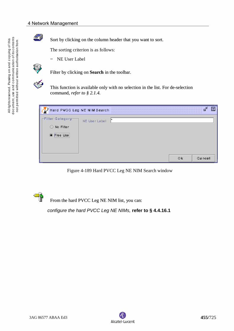
4 Network Management
3AG 86577 ABAA Ed3 455/725
All r
ight
s res
erve
d. P
ass
ing
on
and
cop
ying
of t
his
doc
umen
t, us
e a
nd c
omm
unic
atio
n o
f its
con
tent
sno
t per
mitt
ed w
ithou
t writ
ten
aut
horis
atio
n fro
mA
lca
tel
SSoorrtt bbyy cclliicckkiinngg oonn tthhee ccoolluummnn hheeaaddeerr tthhaatt yyoouu wwaanntt ttoo ssoorrtt..
The sorting criterion is as follows:
− NE User Label
FFiilltteerr bbyy cclliicckkiinngg oonn SSeeaarrcchh iinn tthhee ttoooollbbaarr..
TThhiiss ffuunnccttiioonn iiss aavvaaiillaabbllee oonnllyy wwiitthh nnoo sseelleeccttiioonn iinn tthhee lliisstt.. FFoorr ddee--sseelleeccttiioonnccoommmmaanndd,, rreeffeerr ttoo §§ 22..11..44..
Figure 4-189 Hard PVCC Leg NE NIM Search window
FFrroomm tthhee hhaarrdd PPVVCCCC LLeegg NNEE NNIIMM lliisstt,, yyoouu ccaann::
configure the hard PVCC Leg NE NIMs, refer to § 4.4.16.1

4 Network Management
3AG 86577 ABAA Ed3 456/725
All r
ight
s res
erve
d. P
ass
ing
on
and
cop
ying
of t
his
doc
umen
t, us
e a
nd c
omm
unic
atio
n o
f its
con
tent
sno
t per
mitt
ed w
ithou
t writ
ten
aut
horis
atio
n fro
mA
lca
tel
4.4.16.1 Configure the hard PVCC Leg NE NIMs
This function allows the NIM's configuration of the selected Hard PVCC Leg.
FFrroomm tthhee MMaaiinn vviieeww,, mmeennuu:: MMaannaaggeemmeenntt ==>> HHaarrdd ==>> PPVVCCCC ==>> sseelleecctt oonnee hhaarrddPPVVCCCC ppooiinntt--mmuullttiippooiinntt iinn tthhee lliisstt ==>> LLeegg LLiisstt ==>> sseelleecctt oonnee lleegg iinn tthhee lliisstt ==>> NNEENNIIMM LLiisstt ==>> sseelleecctt oonnee NNEE UUsseerr llaabbeell iinn tthhee lliisstt ==>> CCoonnffiigguurree
Figure 4-190 Hard PVCC Leg NE NIM Configuration window
In the Origin (A) and / or Destination (Z) area(s), tick the Ingress and / or the Egresscheck bock(s) if you want to configure the NIM(s) of the selected NE User Labelchosen in the Hard PVCC Leg NIM List.
Click on Ok.

4 Network Management
3AG 86577 ABAA Ed3 457/725
All r
ight
s res
erve
d. P
ass
ing
on
and
cop
ying
of t
his
doc
umen
t, us
e a
nd c
omm
unic
atio
n o
f its
con
tent
sno
t per
mitt
ed w
ithou
t writ
ten
aut
horis
atio
n fro
mA
lca
tel
In case of NE NIM configuration:
If the hard PVCC Leg provisioning state is established, implemented orcommissioned, a request is sent to the intermediate VCL_Ts chosen by theoperator to create the required NIM Points (on the given direction). The NIMPoint state becomes On NE.
If the hard PVCC Leg provisioning state is allocated, the NIM Point statebecomes On 1354 BM and the NIM Point creation will to be done on the ATMNE at the hard PVPC implementation (the NIM Point state will become On NE).
Configured NIMs are added in the hard PVCC Leg NIM CC List.
In case of NE NIM de-configuration:
If the hard PVCC Leg provisioning state is implemented or commissioned, arequest is sent to each chosen intermediate VCL_T composing the given hardPVCC and supporting an NIM Point, to delete them if no OAM service uses thoseNIMs Points.
If the hard PVCC Leg is de-implemented, all the NIM Points created whenimplemented, are automatically deleted from the ATM NEs. These NIM Pointsare only existing on 1354 BM. The NIM Point state becomes On 1354 BM.

4 Network Management
3AG 86577 ABAA Ed3 458/725
All r
ight
s res
erve
d. P
ass
ing
on
and
cop
ying
of t
his
doc
umen
t, us
e a
nd c
omm
unic
atio
n o
f its
con
tent
sno
t per
mitt
ed w
ithou
t writ
ten
aut
horis
atio
n fro
mA
lca
tel
4.4.17 Display the hard PVCC Leg Constraint list
The hard PVCC Leg Constraint list presents all the hard PVCCs Leg constraintmanaged by the 1354 BM and their descriptive attributes.
FFrroomm tthhee MMaaiinn vviieeww,, mmeennuu:: MMaannaaggeemmeenntt ==>> HHaarrdd ==>> PPVVCCCC ==>> sseelleecctt aa ppooiinntt--mmuullttiippooiinnttss hhaarrdd PPVVCCCC iinn tthhee lliisstt ==>> LLeegg LLiisstt ==>> sseelleecctt aa hhaarrdd PPVVCCCC LLeegg iinn tthhee lliisstt==>> CCoonnssttrraaiinntt
Figure 4-191 Hard PVCC Leg Constraint List window
The descriptive attributes displayed for each hard PVCC constraints are:
− User Label− Constraint Kind− Term. Id.
For column description, refer to chapter 9.
SSoorrtt bbyy cclliicckkiinngg oonn tthhee ccoolluummnn hheeaaddeerr tthhaatt yyoouu wwaanntt ttoo ssoorrtt..
The sorting criterion is as follows:
− User Label

4 Network Management
3AG 86577 ABAA Ed3 459/725
All r
ight
s res
erve
d. P
ass
ing
on
and
cop
ying
of t
his
doc
umen
t, us
e a
nd c
omm
unic
atio
n o
f its
con
tent
sno
t per
mitt
ed w
ithou
t writ
ten
aut
horis
atio
n fro
mA
lca
tel
FFiilltteerr bbyy cclliicckkiinngg oonn SSeeaarrcchh iinn tthhee ttoooollbbaarr..
TThhiiss ffuunnccttiioonn iiss aavvaaiillaabbllee oonnllyy wwiitthh nnoo sseelleeccttiioonn iinn tthhee lliisstt.. FFoorr ddee--sseelleeccttiioonnccoommmmaanndd,, rreeffeerr ttoo §§ 22..11..44..
Figure 4-192 Hard PVCC Leg Constraint Search window
Enter the chosen filtering criteria then click on Ok.
FFrroomm tthhee hhaarrdd PPVVCCCC CCoonnssttrraaiinntt LLiisstt,, yyoouu ccaann::
Add a constraint to a hard PVCC Leg, refer to § 4.4.17.1
Delete a constraint from a hard PVCC Leg, refer to § 4.4.17.2

4 Network Management
3AG 86577 ABAA Ed3 460/725
All r
ight
s res
erve
d. P
ass
ing
on
and
cop
ying
of t
his
doc
umen
t, us
e a
nd c
omm
unic
atio
n o
f its
con
tent
sno
t per
mitt
ed w
ithou
t writ
ten
aut
horis
atio
n fro
mA
lca
tel
4.4.17.1 Add a constraint to a hard PVCC Leg
This function consists in associating one or several allocation constraints to anexisting hard PVCC Leg.
FFrroomm tthhee MMaaiinn vviieeww,, mmeennuu:: MMaannaaggeemmeenntt ==>> HHaarrdd ==>> PPVVCCCC ==>> sseelleecctt aa ppooiinntt--mmuullttiippooiinnttss hhaarrdd PPVVCCCC iinn tthhee lliisstt ==>> LLeegg LLiisstt ==>> sseelleecctt aa hhaarrdd PPVVCCCC LLeegg iinn tthhee lliisstt==>> CCoonnssttrraaiinntt LLiisstt ==>> AAdddd aa ccoonnssttrraaiinntt
TThhiiss ffuunnccttiioonn iiss aavvaaiillaabbllee oonnllyy wwiitthh nnoo sseelleeccttiioonn iinn tthhee ccoonnssttrraaiinntt lliisstt.. FFoorr ddee--sseelleeccttiioonn ccoommmmaanndd,, rreeffeerr ttoo §§ 22..11..44..
Figure 4-193 Hard PVCC Leg Constraint Definition window
To define a hard PVCC Leg constraint:
− Select the Constraint Kind:− Positive Node: consist in defining a list of NE to be crossed− Negative Node: consists in defining some NE that must not be used for the
hard PVPC allocation.− Positive Link: consists in forcing the use of one or several Transmission
Paths.− Negative Link: consists in defining some Transmission Paths that must not
be used for hard PVCC allocation.

4 Network Management
3AG 86577 ABAA Ed3 461/725
All r
ight
s res
erve
d. P
ass
ing
on
and
cop
ying
of t
his
doc
umen
t, us
e a
nd c
omm
unic
atio
n o
f its
con
tent
sno
t per
mitt
ed w
ithou
t writ
ten
aut
horis
atio
n fro
mA
lca
tel
AAllll ccoommbbiinnaattiioonnss ccoonnssttrraaiinntt ffoorrmmss aarree aalllloowweedd..
− For a Node Constraint:− Enter the NE User Label by using the sensitive help
− For a Link Constraint:− Enter a Transmission Path User Label− Enter VPI (optional)
TThhee pprroocceessss ffaaiillss iinn tthhee ffoolllloowwiinngg ccaasseess::− Too many constraints.− One of the constraint does not correspond to en existing entity.− One of the constraint is given more than one time in the lists.

4 Network Management
3AG 86577 ABAA Ed3 462/725
All r
ight
s res
erve
d. P
ass
ing
on
and
cop
ying
of t
his
doc
umen
t, us
e a
nd c
omm
unic
atio
n o
f its
con
tent
sno
t per
mitt
ed w
ithou
t writ
ten
aut
horis
atio
n fro
mA
lca
tel
4.4.17.2 Delete a constraint from a hard PVCC Leg
This function consists in deleting constraints from a Hard PVPC.
-- TThhee ccoonnssttrraaiinntt ooff tthhee hhaarrdd PPVVCCCC LLeegg mmuusstt bbee CCrreeaatteedd..
FFrroomm tthhee MMaaiinn vviieeww,, mmeennuu:: MMaannaaggeemmeenntt ==>> HHaarrdd ==>> PPVVCCCC ==>> sseelleecctt aa hhaarrddPPVVCCCC ==>> LLeegg LLiisstt ==>> sseelleecctt aa hhaarrdd PPVVCCCC LLeegg iinn tthhee lliisstt ==>> CCoonnssttrraaiinntt LLiisstt ==>>sseelleecctt oonnee oorr sseevveerraall ccoonnssttrraaiinnttss iinn tthhee lliisstt ==>> DDeelleettee
A confirmation box is displayed:
Figure 4-194 Confirmation box for deleting a Constraint from a Hard PVCC Leg
Figure 4-195 Confirmation box for deleting several Constraints from a Hard PVCC Leg
After confirmation, the Constraints are removed.
The constraints list is updated.

4 Network Management
3AG 86577 ABAA Ed3 463/725
All r
ight
s res
erve
d. P
ass
ing
on
and
cop
ying
of t
his
doc
umen
t, us
e a
nd c
omm
unic
atio
n o
f its
con
tent
sno
t per
mitt
ed w
ithou
t writ
ten
aut
horis
atio
n fro
mA
lca
tel
4.5 Managing soft PVPCs
The soft PVPC management, part of the network management, consists in:
− performing actions such as:defining soft PVPCs:− traffic profile− extremities
deleting, modifying soft PVPCssetting in/out of service soft PVPCs:− set-up/release function− activating / deactivating the continuity check on soft PVPCs− activating / deactivating the output shaping on soft PVPCs− activating / deactivating the UPC/NPC on soft PVPCs
− displaying soft PVPC information such as:− soft PVPC list− extremities and properties− bandwidth load, traffic and routing− graphical view
The soft PVPC management chain gives the order in which the available actions maybe performed.
Define
Set-up
Delete
Release
Activate/deactivate CC
Modify
Activate/ deactivateoutput shaping
Activate/ deactivateUPC/NPC
Figure 4-196 Soft PVPC management chain

4 Network Management
3AG 86577 ABAA Ed3 464/725
All r
ight
s res
erve
d. P
ass
ing
on
and
cop
ying
of t
his
doc
umen
t, us
e a
nd c
omm
unic
atio
n o
f its
con
tent
sno
t per
mitt
ed w
ithou
t writ
ten
aut
horis
atio
n fro
mA
lca
tel
The figure below shows the evolution of the provisioning state according to theoperation performed on the soft PVPC.
Defined
Established
Define
Set-up
Release
Delete
Establishing
Figure 4-197 Soft PVPC provisioning state
The soft PVPC management is performed from the Soft PVPC List window thatincludes two panels as follows:
− Description− Characteristics
For managing soft PVPCs, you can:
display the soft PVPC description list, refer to § 4.5.1
display the soft PVPC characteristic list, refer to § 4.5.7

4 Network Management
3AG 86577 ABAA Ed3 465/725
All r
ight
s res
erve
d. P
ass
ing
on
and
cop
ying
of t
his
doc
umen
t, us
e a
nd c
omm
unic
atio
n o
f its
con
tent
sno
t per
mitt
ed w
ithou
t writ
ten
aut
horis
atio
n fro
mA
lca
tel
4.5.1 Display the soft PVPC description list
The soft PVPC description list presents all the soft PVPCs managed by the 1354 BMand their descriptive attributes.
FFrroomm tthhee MMaaiinn vviieeww,, mmeennuu:: MMaannaaggeemmeenntt ==>> SSoofftt ==>> PPVVPPCC ==>> sseelleecctt tthheeDDeessccrriippttiioonn ppaanneell
Figure 4-198 Soft PVPC List window – Description panel
The descriptive attributes displayed for each soft PVPC are:
− User Label− Provis. State− Traffic Contract− Calling conn. End Point− Called conn. End Point− Parent Sub-network User LabelFor column description, refer to chapter 9.
SSoorrtt bbyy cclliicckkiinngg oonn tthhee ccoolluummnn hheeaaddeerr tthhaatt yyoouu wwaanntt ttoo ssoorrtt..
The sorting criteria are as follows:
− User Label− Parent Sub-network User Label

4 Network Management
3AG 86577 ABAA Ed3 466/725
All r
ight
s res
erve
d. P
ass
ing
on
and
cop
ying
of t
his
doc
umen
t, us
e a
nd c
omm
unic
atio
n o
f its
con
tent
sno
t per
mitt
ed w
ithou
t writ
ten
aut
horis
atio
n fro
mA
lca
tel
FFiilltteerr bbyy cclliicckkiinngg oonn SSeeaarrcchh iinn tthhee ttoooollbbaarr..
TThhiiss ffuunnccttiioonn iiss aavvaaiillaabbllee oonnllyy wwiitthh nnoo sseelleeccttiioonn iinn tthhee lliisstt.. FFoorr ddee--sseelleeccttiioonnccoommmmaanndd,, rreeffeerr ttoo §§ 22..11..44..
Figure 4-199 Soft PVPC Description Search window
Enter the chosen filtering criteria then click on Ok.

4 Network Management
3AG 86577 ABAA Ed3 467/725
All r
ight
s res
erve
d. P
ass
ing
on
and
cop
ying
of t
his
doc
umen
t, us
e a
nd c
omm
unic
atio
n o
f its
con
tent
sno
t per
mitt
ed w
ithou
t writ
ten
aut
horis
atio
n fro
mA
lca
tel
FFrroomm tthhee ssoofftt PPVVPPCC ddeessccrriippttiioonn lliisstt,, yyoouu ccaann::
define a soft PVPC, refer to § 4.5.2
modify a soft PVPC, refer to § 4.5.3
delete a soft PVPC, refer to § 4.5.4
set-up a soft PVPC, refer to § 4.5.5
release a soft PVPC, refer to § 4.5.6
display the soft PVPC characteristics list, refer to § 4.5.7
activate the output shaping on a soft PVPC, refer to § 4.5.8
deactivate the output shaping on a soft PVPC, refer to § 4.5.9
activate UPC / NPC on a soft PVPC, refer to § 4.5.10
deactivate UPC / NPC on a soft PVPC, refer to § 4.5.11
display the soft PVPC extremities, refer to § 4.5.12
display the soft PVPC properties, refer to § 4.5.13
display the soft PVPC bandwidth load, refer to § 4.5.14
display the soft PVPC traffic properties, refer to § 4.5.15
display the soft PVPC routing properties, refer to § 4.5.16
activate/deactivate the CC on a soft PVPC (change CC direction), refer to §4.5.17
display the soft PVPC graphical view, refer to § 4.5.18

4 Network Management
3AG 86577 ABAA Ed3 468/725
All r
ight
s res
erve
d. P
ass
ing
on
and
cop
ying
of t
his
doc
umen
t, us
e a
nd c
omm
unic
atio
n o
f its
con
tent
sno
t per
mitt
ed w
ithou
t writ
ten
aut
horis
atio
n fro
mA
lca
tel
4.5.2 Define a soft PVPC
This function consists in identifying the soft PVPC and determining its traffic profileand the NEs (and/or ENEs) that support its extremities. To have more informationabout Soft PVPC, refer to § 1.4.2
-- TThhee NNEEss ((aanndd//oorr EENNEEss)) ssuuppppoorrttiinngg tthhee eexxttrreemmiittiieess ooff tthhee ssoofftt PPVVPPCC mmuusstt bbeepprreevviioouussllyy ddeeffiinneedd..
-- BBootthh ttrraannssmmiissssiioonn ppaatthhss ssuuppppoorrttiinngg tthhee eexxttrreemmiittiieess ooff tthhee ssoofftt PPVVPPCC mmuusstt eexxiissttaanndd bbee ccoonnffiigguurreedd wwiitthh tthhee ssaammee ccoonnffiigguurraattiioonn..
-- TThhee mmaaxxiimmuumm nnuummbbeerr ooff PPVVPPCCss mmuusstt nnoott bbee rreeaacchheedd..
FFrroomm tthhee MMaaiinn vviieeww,, mmeennuu:: MMaannaaggeemmeenntt ==>> SSoofftt ==>> PPVVPPCC ==>> sseelleecctt tthheeDDeessccrriippttiioonn ppaanneell ==>> DDeeffiinnee SSoofftt PPVVPPCC
TThhiiss ffuunnccttiioonn iiss aavvaaiillaabbllee oonnllyy wwiitthh nnoo sseelleeccttiioonn iinn tthhee lliisstt.. FFoorr ddee--sseelleeccttiioonnccoommmmaanndd,, rreeffeerr ttoo §§ 22..11..44..

4 Network Management
3AG 86577 ABAA Ed3 469/725
All r
ight
s res
erve
d. P
ass
ing
on
and
cop
ying
of t
his
doc
umen
t, us
e a
nd c
omm
unic
atio
n o
f its
con
tent
sno
t per
mitt
ed w
ithou
t writ
ten
aut
horis
atio
n fro
mA
lca
tel
Figure 4-200 Soft PVPC Definition window
To define a soft PVPC:
− Enter a PVPC User Label− Enter a Comment (optional).− In the Profile area:
− Choose the traffic profile by using the Service Type and Description optionbuttons (the items proposed by the Description option button depend on theService Type previously chosen).
− To get detailed information about the parameters of the chosen profile, clickon Properties. The window becomes as below.

4 Network Management
3AG 86577 ABAA Ed3 470/725
All r
ight
s res
erve
d. P
ass
ing
on
and
cop
ying
of t
his
doc
umen
t, us
e a
nd c
omm
unic
atio
n o
f its
con
tent
sno
t per
mitt
ed w
ithou
t writ
ten
aut
horis
atio
n fro
mA
lca
tel
Figure 4-201 Soft PVPC Definition window (extended view)
TThhee ttrraaffffiicc ccoonnttrraaccttss ooff SSoofftt VVPPCCss wwhhiicchh aarree aauutthhoorriizzeedd aarree::
− DBR Class 1− DBR Class U (UBR.1) cell based− DBR Class U (UBR.2) cell based− UBR + (= DBR Class U (UBR.2) with MCR > 0) cell based
− In the Calling End Point and Called End Point areas, enter the identificationparameters of the NEs and/or ENEs that support the soft PVPC extremities:− Only for the called end point, tick the ENE check box if the extremity is
supported by an ENE.− Choose the NE (or ENE) User Label by using the sensitive help.− Choose the Termination Id. by using the sensitive help.− Enter an ATM Address number.− Enter a VPI number.

4 Network Management
3AG 86577 ABAA Ed3 471/725
All r
ight
s res
erve
d. P
ass
ing
on
and
cop
ying
of t
his
doc
umen
t, us
e a
nd c
omm
unic
atio
n o
f its
con
tent
sno
t per
mitt
ed w
ithou
t writ
ten
aut
horis
atio
n fro
mA
lca
tel
− Optional parameters: in the Calling Connection End Point and CalledConnection End Point areas, enter the identification parameters of the NEsand/or ENEs that support the extremities of the hard PVPCs associated to thesoft PVPC:− Tick the ENE check box if the extremity is supported by an ENE.− Choose the NE (or ENE) User Label by using the sensitive help.− Choose the Termination Id. by using the sensitive help.− Enter a VPI number.
IIff tthhee ccoonnnneeccttiioonn eennddppooiinntt iiss nnoott ssppeecciiffiieedd,, iitt iiss ddeedduucceedd bbyy tthhee 11335544 BBMM,, aass bbeeiinnggtthhee ppooiinntt ccoonnttiigguuoouuss ttoo tthhee rreessppeeccttiivvee ccaalllliinngg//ccaalllleedd eennddppooiinntt..
− Click on Ok.
The soft PVPC is defined into the 1354 BM with the following states:
− provisioning state : Defined− availability status : None (not significant)− UPC/NPC state :− Disabled if the interface types of the transmission paths of both extremities
are NNI− Enabled if the interface type of at least one transmission path of both
extremities is ICI or UNI− shaping state : Disabled
The soft PVPC description and characteristic lists are updated.

4 Network Management
3AG 86577 ABAA Ed3 472/725
All r
ight
s res
erve
d. P
ass
ing
on
and
cop
ying
of t
his
doc
umen
t, us
e a
nd c
omm
unic
atio
n o
f its
con
tent
sno
t per
mitt
ed w
ithou
t writ
ten
aut
horis
atio
n fro
mA
lca
tel
4.5.3 Modify a soft PVPC
The soft PVPC modification gives the possibility to modify:
User LabelComment
-- TThhee pprroovviissiioonniinngg ssttaattee ooff tthhee ssoofftt PPVVPPCC mmuusstt bbee DDeeffiinneedd..
FFrroomm tthhee MMaaiinn vviieeww,, mmeennuu:: MMaannaaggeemmeenntt ==>> SSoofftt ==>> PPVVPPCC ==>> sseelleecctt tthheeDDeessccrriippttiioonn ppaanneell ==>> sseelleecctt oonnee oorr sseevveerraall ssoofftt PPVVPPCCss iinn tthhee lliisstt ==>> DDeelleettee
A confirmation box is displayed:
Figure 4-202 Soft PVPC Modification
After confirmation, the parameters of the soft PVPC are modified.
The soft PVPC description and characteristic lists are updated.

4 Network Management
3AG 86577 ABAA Ed3 473/725
All r
ight
s res
erve
d. P
ass
ing
on
and
cop
ying
of t
his
doc
umen
t, us
e a
nd c
omm
unic
atio
n o
f its
con
tent
sno
t per
mitt
ed w
ithou
t writ
ten
aut
horis
atio
n fro
mA
lca
tel
4.5.4 Delete a soft PVPC
This function consists in deleting a soft PVPC from the 1354 BM supervision.
-- TThhee pprroovviissiioonniinngg ssttaattee ooff tthhee ssoofftt PPVVPPCC mmuusstt bbee DDeeffiinneedd..
FFrroomm tthhee MMaaiinn vviieeww,, mmeennuu:: MMaannaaggeemmeenntt ==>> SSoofftt ==>> PPVVPPCC ==>> sseelleecctt tthheeDDeessccrriippttiioonn ppaanneell ==>> sseelleecctt oonnee oorr sseevveerraall ssoofftt PPVVPPCCss iinn tthhee lliisstt ==>> DDeelleettee
A confirmation box is displayed:
Figure 4-203 Confirmation box for deleting one soft PVPC
Figure 4-204 Confirmation box for deleting several soft PVPCs
After confirmation, the soft PVPCs are removed.
The soft PVPC description and characteristic lists are updated.

4 Network Management
3AG 86577 ABAA Ed3 474/725
All r
ight
s res
erve
d. P
ass
ing
on
and
cop
ying
of t
his
doc
umen
t, us
e a
nd c
omm
unic
atio
n o
f its
con
tent
sno
t per
mitt
ed w
ithou
t writ
ten
aut
horis
atio
n fro
mA
lca
tel
4.5.5 Set-up a soft PVPC
This function consists in setting in service a soft PVPC. This establishes a connectionusing PNNI.
-- TThhee pprroovviissiioonniinngg ssttaattee ooff tthhee ssoofftt PPVVPPCC mmuusstt bbee ddeeffiinneedd..
-- BBootthh ccaalllliinngg aanndd ccaalllleedd NNEEss mmuusstt bbeelloonngg ttoo aa ppeeeerr ggrroouupp ((nnoott iimmpplleemmeenntteedd iinnrreelleeaassee RR77))..
FFrroomm tthhee MMaaiinn vviieeww,, mmeennuu:: MMaannaaggeemmeenntt ==>> SSoofftt ==>> PPVVPPCC ==>> sseelleecctt tthheeDDeessccrriippttiioonn ppaanneell ==>> sseelleecctt oonnee oorr sseevveerraall ddeeffiinneedd ssoofftt PPVVPPCCss iinn tthhee lliisstt ==>> SSeett--uupp
A confirmation box is displayed:
Figure 4-205 Confirmation box for setting-up one soft PVPC
Figure 4-206 Confirmation box for setting-up several soft PVPCs
After confirmation, the soft PVPC set-up process is launched. The 1354 BM:− creates the hard PVPC between the calling end point and the calling connection
end point− creates the hard PVPC between the called end point and the called connection end
point, except if the called end point is an ENE− allocates, implements and commissions the hard PVPC(s)− sends a set-up request to the calling NE so that it searches for a path to reach the
called NE
The calling ATM NE is in charge of searching a path to reach the called ATM NE.
If there is no way to establish the soft PVPC by using the existing resources, newtransmission paths have to be created before the user requests another set-up.

4 Network Management
3AG 86577 ABAA Ed3 475/725
All r
ight
s res
erve
d. P
ass
ing
on
and
cop
ying
of t
his
doc
umen
t, us
e a
nd c
omm
unic
atio
n o
f its
con
tent
sno
t per
mitt
ed w
ithou
t writ
ten
aut
horis
atio
n fro
mA
lca
tel
The provisioning state changes to Establishing if the NE accepts the set-up request.
If the set-up is successful, the soft PVPC provisioning state changes to Establishingand its availability status is updated and managed in function of the alarms. The softPVPC description and characteristic lists are updated.

4 Network Management
3AG 86577 ABAA Ed3 476/725
All r
ight
s res
erve
d. P
ass
ing
on
and
cop
ying
of t
his
doc
umen
t, us
e a
nd c
omm
unic
atio
n o
f its
con
tent
sno
t per
mitt
ed w
ithou
t writ
ten
aut
horis
atio
n fro
mA
lca
tel
4.5.6 Release a soft PVPC
This function consists in setting out of service a soft PVPC.
-- TThhee pprroovviissiioonniinngg ssttaattee ooff aallll tthhee ssoofftt PPVVCCCCss ppaassssiinngg tthhrroouugghh tthhee ssoofftt PPVVPPCC mmuussttbbee DDeeffiinneedd..
-- TThhee pprroovviissiioonniinngg ssttaattee ooff tthhee ssoofftt PPVVPPCC mmuusstt bbee EEssttaabblliisshheedd oorr EEssttaabblliisshhiinngg..
-- TThhee ssoofftt PPVVPPCC mmuusstt nnoott bbee aassssoocciiaatteedd ttoo aa PPMM MMeeaassuurree..
FFrroomm tthhee MMaaiinn vviieeww,, mmeennuu:: MMaannaaggeemmeenntt ==>> SSoofftt ==>> PPVVPPCC ==>> sseelleecctt tthheeDDeessccrriippttiioonn ppaanneell ==>> sseelleecctt oonnee oorr sseevveerraall eessttaabblliisshheedd ssoofftt PPVVPPCCss iinn tthhee lliisstt ==>>RReelleeaassee
A confirmation box is displayed:
Figure 4-207 Confirmation box for releasing one soft PVPC
Figure 4-208 Confirmation box for releasing several soft PVPCs
After confirmation, the soft PVPC release process is launched. The 1354 BM:
− sends the release resquest to the calling NE that is in charge of releasing theresources used by the soft PVPC
− de-commissions, de-implements, de-allocates and delete the hard PVPC(s)associated to the soft PVPC.
When the release process is finished, the soft PVPC provisional state changes toDefined and its availability status changes to None (no more significant).
The soft PVPC description and characteristic lists are updated.

4 Network Management
3AG 86577 ABAA Ed3 477/725
All r
ight
s res
erve
d. P
ass
ing
on
and
cop
ying
of t
his
doc
umen
t, us
e a
nd c
omm
unic
atio
n o
f its
con
tent
sno
t per
mitt
ed w
ithou
t writ
ten
aut
horis
atio
n fro
mA
lca
tel
4.5.7 Display the soft PVPC characteristic listThe soft PVPC characteristic list presents all the soft PVPCs managed by the 1354BM and their characteristic attributes.
FFrroomm tthhee MMaaiinn vviieeww,, mmeennuu:: MMaannaaggeemmeenntt ==>> SSoofftt ==>> PPVVPPCC ==>> sseelleecctt tthheeCChhaarraacctteerriissttiiccss ppaanneell
Figure 4-209 Soft PVPC List window – Characteristics panel
The characteristic attributes displayed for each soft PVPC are:
− User Label− Provis. State− Direction− VCI Range− Interface Type− Shap. State− Shaping Mode− UPC / NPC state− Avail. Status
For column description, refer to chapter 9.
SSoorrtt bbyy cclliicckkiinngg oonn tthhee ccoolluummnn hheeaaddeerr tthhaatt yyoouu wwaanntt ttoo ssoorrtt..
The sorting criterion is as follows:
− User Label
FFiilltteerr bbyy cclliicckkiinngg oonn SSeeaarrcchh iinn tthhee ttoooollbbaarr..
TThhiiss ffuunnccttiioonn iiss aavvaaiillaabbllee oonnllyy wwiitthh nnoo sseelleeccttiioonn iinn tthhee lliisstt.. FFoorr ddee--sseelleeccttiioonnccoommmmaanndd,, rreeffeerr ttoo §§ 22..11..44..

4 Network Management
3AG 86577 ABAA Ed3 478/725
All r
ight
s res
erve
d. P
ass
ing
on
and
cop
ying
of t
his
doc
umen
t, us
e a
nd c
omm
unic
atio
n o
f its
con
tent
sno
t per
mitt
ed w
ithou
t writ
ten
aut
horis
atio
n fro
mA
lca
tel
Figure 4-210 Soft PVPC Characteristics Search window
Enter the chosen filtering criteria then click on Ok.
FFrroomm tthhee ssoofftt PPVVPPCC cchhaarraacctteerriissttiicc lliisstt,, yyoouu ccaann::
define a soft PVPC, refer to § 4.5.2
modify a soft PVPC, refer to § 4.5.3
delete a soft PVPC, refer to § 4.5.4
set-up a soft PVPC, refer to § 4.5.5
release a soft PVPC, refer to § 4.5.6
activate the output shaping on a soft PVPC, refer to § 4.5.8
deactivate the output shaping on a soft PVPC, refer to § 4.5.9
activate UPC / NPC on a soft PVPC, refer to § 4.5.10
deactivate UPC / NPC on a soft PVPC, refer to § 4.5.11
display the soft PVPC extremities, refer to § 4.5.12
display the soft PVPC properties, refer to § 4.5.13
display the soft PVPC bandwidth load, refer to § 4.5.14
display the soft PVPC traffic properties, refer to § 4.5.15
display the soft PVPC routing properties, refer to § 4.5.16
activate/deactivate the CC on a soft PVPC (change CC direction), refer to §4.5.17

4 Network Management
3AG 86577 ABAA Ed3 479/725
All r
ight
s res
erve
d. P
ass
ing
on
and
cop
ying
of t
his
doc
umen
t, us
e a
nd c
omm
unic
atio
n o
f its
con
tent
sno
t per
mitt
ed w
ithou
t writ
ten
aut
horis
atio
n fro
mA
lca
tel
display the soft PVPC graphical view, refer to § 4.5.18

4 Network Management
3AG 86577 ABAA Ed3 480/725
All r
ight
s res
erve
d. P
ass
ing
on
and
cop
ying
of t
his
doc
umen
t, us
e a
nd c
omm
unic
atio
n o
f its
con
tent
sno
t per
mitt
ed w
ithou
t writ
ten
aut
horis
atio
n fro
mA
lca
tel
4.5.8 Activate the output shaping on a soft PVPC
This function consists in enabling the output shaping feature on a soft PVPC.
The output shaping is used to delay some cells in order not to overflow thenegotiated PCR.
-- TThhee pprroovviissiioonniinngg ssttaattee ooff tthhee ssoofftt PPVVPPCC mmuusstt bbee DDeeffiinneedd..
-- TThhee sshhaappiinngg ssttaattee ooff tthhee ssoofftt PPVVPPCC mmuusstt bbee DDiissaabblleedd..
-- TThhee ttrraaffffiicc ccoonnttrraacctt ooff tthhee ssoofftt PPVVPPCC mmuusstt bbee DDBBRR ccllaassss 11 wwiitthh aa PPCCRR ggrreeaatteerr oorreeqquuaall ttoo 118800 cceellll//ss..
-- AAllll tthhee AATTMM NNEEss uusseedd bbyy tthhee ssoofftt PPVVPPCC hhaavvee ttoo ssuuppppoorrtt tthhee oouuttppuutt sshhaappiinnggffeeaattuurree..
-- TThhee mmaaxxiimmuumm nnuummbbeerr ooff sshhaappeedd PPVVPPCC mmuusstt nnoott bbee rreeaacchheedd..
FFrroomm tthhee MMaaiinn vviieeww,, mmeennuu:: MMaannaaggeemmeenntt ==>> SSoofftt ==>> PPVVPPCC ==>> sseelleecctt tthheeCChhaarraacctteerriissttiiccss ppaanneell ==>> sseelleecctt oonnee oorr sseevveerraall ssoofftt PPVVPPCCss iinn tthhee lliisstt ==>> AAcctt.. SShhaapp..
A confirmation box is displayed:
Figure 4-211 Confirmation box for activating the output shaping on one soft PVPC
Figure 4-212 Confirmation box for activating the output shaping on several soft PVPCs

4 Network Management
3AG 86577 ABAA Ed3 481/725
All r
ight
s res
erve
d. P
ass
ing
on
and
cop
ying
of t
his
doc
umen
t, us
e a
nd c
omm
unic
atio
n o
f its
con
tent
sno
t per
mitt
ed w
ithou
t writ
ten
aut
horis
atio
n fro
mA
lca
tel
To activate the output shaping on one soft PVPC:
− Choose the location where the output shaping will be activated, by using theShaping Protection Mode option button.
− Click on Ok.
To activate the output shaping on several soft PVPCs:
− If you click on All, the parameter is available for all the selected soft PVPCs.− If you click on Yes, the parameter is available only for the soft PVPC currently
displayed in the confirmation box.
The shaping state of the soft PVPC changes to Enabled.
At next set-up of the soft PVPC, the output shaping activation request will be sent tothe chosen NEs.
The soft PVPC characteristic list is updated.

4 Network Management
3AG 86577 ABAA Ed3 482/725
All r
ight
s res
erve
d. P
ass
ing
on
and
cop
ying
of t
his
doc
umen
t, us
e a
nd c
omm
unic
atio
n o
f its
con
tent
sno
t per
mitt
ed w
ithou
t writ
ten
aut
horis
atio
n fro
mA
lca
tel
4.5.9 Deactivate the output shaping on a soft PVPC
This function consists in disabling the output shaping function on a soft PVPC.
-- TThhee sshhaappiinngg ssttaattee ooff tthhee ssoofftt PPVVPPCC mmuusstt bbee EEnnaabblleedd..
FFrroomm tthhee MMaaiinn vviieeww,, mmeennuu:: MMaannaaggeemmeenntt ==>> SSoofftt ==>> PPVVPPCC ==>> sseelleecctt tthheeCChhaarraacctteerriissttiiccss ppaanneell ==>> sseelleecctt oonnee oorr sseevveerraall ssoofftt PPVVPPCCss iinn tthhee lliisstt ==>> DDeeaacctt..SShhaapp..
A confirmation box is displayed:
Figure 4-213 Confirmation box for deactivating the output shaping on one soft PVPC
Figure 4-214 Confirmation box for deactivating the output shaping on several soft PVPCs
After confirmation, the shaping state of the soft PVPCs change to Disabled.
The soft PVPC characteristic list is updated.

4 Network Management
3AG 86577 ABAA Ed3 483/725
All r
ight
s res
erve
d. P
ass
ing
on
and
cop
ying
of t
his
doc
umen
t, us
e a
nd c
omm
unic
atio
n o
f its
con
tent
sno
t per
mitt
ed w
ithou
t writ
ten
aut
horis
atio
n fro
mA
lca
tel
4.5.10 Activate UPC / NPC on a soft PVPC
This function consists in activating an ATM police control on a soft PVPC thatpasses through the ATM network.
-- TThhee pprroovviissiioonniinngg ssttaattee ooff tthhee ssoofftt PPVVPPCC mmuusstt bbee DDeeffiinneedd..
-- TThhee UUPPCC // NNPPCC ssttaattee ooff tthhee ssoofftt PPVVPPCC mmuusstt bbee DDiissaabblleedd..
-- AAtt lleeaasstt oonnee ttrraannssmmiissssiioonn ppaatthh uusseedd aatt tthhee eexxttrreemmiittyy ooff tthhee ssoofftt PPVVPPCC mmuusstt hhaavveeaann IICCII oorr UUNNII iinntteerrffaaccee ttyyppee..
WWhheenn tthheessee ccoonnddiittiioonnss aarree rreessppeecctteedd,, tthhee UUPPCC // NNPPCC iiss bbyy ddeeffaauulltt aaccttiivvaatteedd..
FFrroomm tthhee MMaaiinn vviieeww,, mmeennuu:: MMaannaaggeemmeenntt ==>> SSoofftt ==>> PPVVPPCC ==>> sseelleecctt tthheeCChhaarraacctteerriissttiiccss ppaanneell ==>> sseelleecctt oonnee oorr sseevveerraall ssoofftt PPVVPPCCss iinn tthhee lliisstt ==>> AAcctt.. UUPPCC
A confirmation box is displayed:
Figure 4-215 Confirmation box for activating UPC / NPC on one soft PVPC
Figure 4-216 Confirmation box for activating UPC / NPC on several soft PVPCs
After confirmation, the UPC / NPC state of each soft PVPC changes to Enabled.
At next implementation of the soft PVPC, the UPC / NPC activation request will besent to the first NE (linked to the ENE) in the border of the network.
The soft PVPC characteristic list is updated.

4 Network Management
3AG 86577 ABAA Ed3 484/725
All r
ight
s res
erve
d. P
ass
ing
on
and
cop
ying
of t
his
doc
umen
t, us
e a
nd c
omm
unic
atio
n o
f its
con
tent
sno
t per
mitt
ed w
ithou
t writ
ten
aut
horis
atio
n fro
mA
lca
tel
4.5.11 Deactivate UPC / NPC on a soft PVPC
This function consists in deactivating the ATM police control on a soft PVPC.
-- TThhee UUPPCC // NNPPCC ssttaattee ooff tthhee ssoofftt PPVVPPCC mmuusstt bbee EEnnaabblleedd..
FFrroomm tthhee MMaaiinn vviieeww,, mmeennuu:: MMaannaaggeemmeenntt ==>> SSoofftt ==>> PPVVPPCC ==>> sseelleecctt tthheeCChhaarraacctteerriissttiiccss ppaanneell ==>> sseelleecctt oonnee oorr sseevveerraall ssoofftt PPVVPPCCss iinn tthhee lliisstt ==>> DDeeaacctt.. UUPPCC
A confirmation box is displayed:
Figure 4-217 Confirmation box for deactivating UPC / NPC on one soft PVPC
Figure 4-218 Confirmation box for deactivating UPC / NPC on several soft PVPCs
After confirmation, the UPC / NPC state of each soft PVPC changes to Disabled.
The soft PVPC characteristic list is updated.

4 Network Management
3AG 86577 ABAA Ed3 485/725
All r
ight
s res
erve
d. P
ass
ing
on
and
cop
ying
of t
his
doc
umen
t, us
e a
nd c
omm
unic
atio
n o
f its
con
tent
sno
t per
mitt
ed w
ithou
t writ
ten
aut
horis
atio
n fro
mA
lca
tel
4.5.12 Display the soft PVPC extremities
This function consists in displaying information about the ATM NEs (and/or ENEs)that support the soft PVPC extremities.
FFrroomm tthhee MMaaiinn vviieeww,, mmeennuu:: MMaannaaggeemmeenntt ==>> SSoofftt ==>> PPVVPPCC ==>> sseelleecctt tthheeCChhaarraacctteerriissttiiccss ppaanneell ==>> sseelleecctt aa ssoofftt PPVVPPCC iinn tthhee lliisstt ==>> EExxttrreemmiittiieess
Figure 4-219 Soft PVPC Extremities window
The fields have been filled out at the soft PVPC definition (refer to § 4.5.2) time.

4 Network Management
3AG 86577 ABAA Ed3 486/725
All r
ight
s res
erve
d. P
ass
ing
on
and
cop
ying
of t
his
doc
umen
t, us
e a
nd c
omm
unic
atio
n o
f its
con
tent
sno
t per
mitt
ed w
ithou
t writ
ten
aut
horis
atio
n fro
mA
lca
tel
4.5.13 Display the soft PVPC properties
This function consists in displaying information about the last action performed on asoft PVPC.
FFrroomm tthhee MMaaiinn vviieeww,, mmeennuu:: MMaannaaggeemmeenntt ==>> SSoofftt ==>> PPVVPPCC ==>> sseelleecctt tthheeCChhaarraacctteerriissttiiccss ppaanneell ==>> sseelleecctt aa ssoofftt PPVVPPCC iinn tthhee lliisstt ==>> PPrrooppeerrttiieess
Figure 4-220 Soft PVPC Properties window
The first fields have been filled out at the soft PVPC definition (refer to § 4.5.2) time.
The last two ones give information about the last action performed on the soft PVPC.

4 Network Management
3AG 86577 ABAA Ed3 487/725
All r
ight
s res
erve
d. P
ass
ing
on
and
cop
ying
of t
his
doc
umen
t, us
e a
nd c
omm
unic
atio
n o
f its
con
tent
sno
t per
mitt
ed w
ithou
t writ
ten
aut
horis
atio
n fro
mA
lca
tel
4.5.14 Display the soft PVPC bandwidth load
This function consists in displaying information about the soft PVPC bandwidth loadand the number of soft PVCCs using this soft PVPC.
-- TThhee pprroovviissiioonniinngg ssttaattee ooff tthhee ssoofftt PPVVPPCC mmuusstt bbee EEssttaabblliisshhiinngg oorr EEssttaabblliisshheedd..
FFrroomm tthhee MMaaiinn vviieeww,, mmeennuu:: MMaannaaggeemmeenntt ==>> SSoofftt ==>> PPVVPPCC ==>> sseelleecctt tthheeCChhaarraacctteerriissttiiccss ppaanneell ==>> sseelleecctt aa ssoofftt PPVVPPCC iinn tthhee lliisstt ==>> BBaannddwwiiddtthh LLooaadd
Figure 4-221 Soft PVPC Bandwidth Load window

4 Network Management
3AG 86577 ABAA Ed3 488/725
All r
ight
s res
erve
d. P
ass
ing
on
and
cop
ying
of t
his
doc
umen
t, us
e a
nd c
omm
unic
atio
n o
f its
con
tent
sno
t per
mitt
ed w
ithou
t writ
ten
aut
horis
atio
n fro
mA
lca
tel
The window is split into three areas:
− The Forward Bandwidth and the Backward Bandwidth areas give the followinginformation for each direction used by the PVCCs:− Total (cell/s): total number of cells per second passing through the soft PVPC− Established (%): percentage of bandwidth used by PVCCs whose
provisioning state is Established or Establishing− Available (%): percentage of bandwidth not used by any PVCCs− Bar-chart showing in another way the previous percentages
− The Nb. VCI area gives:− the total number of VCIs using the PVPC− the number of VCIs established
AAllll tthhee ffoorrwwaarrdd bbaannddwwiiddtthh vvaalluueess aarree sseett ttoo zzeerroo iinn tthhee ffoolllloowwiinngg ccaasseess::
− The called end point extremity is an ENE− The called connection end point extremity is an ENE− The calling connection end point extremity is an ENE

4 Network Management
3AG 86577 ABAA Ed3 489/725
All r
ight
s res
erve
d. P
ass
ing
on
and
cop
ying
of t
his
doc
umen
t, us
e a
nd c
omm
unic
atio
n o
f its
con
tent
sno
t per
mitt
ed w
ithou
t writ
ten
aut
horis
atio
n fro
mA
lca
tel
4.5.15 Display the soft PVPC traffic properties
This function consists in displaying information about the traffic contract performedby a soft PVPC.
FFrroomm tthhee MMaaiinn vviieeww,, mmeennuu:: MMaannaaggeemmeenntt ==>> SSoofftt ==>> PPVVPPCC ==>> sseelleecctt tthheeCChhaarraacctteerriissttiiccss ppaanneell ==>> sseelleecctt aa ssoofftt PPVVPPCC iinn tthhee lliisstt ==>> TTrraaffffiicc
Figure 4-222 Soft PVPC Traffic Properties window
TThhee nnuummbbeerr ooff iitteemmss ddiissppllaayyeedd iinn tthhee FFoorrwwaarrdd aanndd BBaacckkwwaarrdd aarreeaass ddeeppeennddss oonn tthheettrraaffffiicc ccoonnttrraacctt..

4 Network Management
3AG 86577 ABAA Ed3 490/725
All r
ight
s res
erve
d. P
ass
ing
on
and
cop
ying
of t
his
doc
umen
t, us
e a
nd c
omm
unic
atio
n o
f its
con
tent
sno
t per
mitt
ed w
ithou
t writ
ten
aut
horis
atio
n fro
mA
lca
tel
4.5.16 Display the soft PVPC routing properties
This function consists in displaying information about the transmission paths andVPis used by a soft PVPC.
Not implemented in release R7.
4.5.17 Activate/deactivate the CC on a soft PVPC (change CCdirection)
This function consists in activating/deactivating the Continuity Check (CC) for oneor both directions of a soft PVPC.
Not implemented in release R7.
4.5.18 Display the soft PVPC graphical view
This function consists in displaying the graphical view (transmission path domain)corresponding to the sub-network that contains the transmission paths used by thesoft PVPC.
Not implemented in release R7.

4 Network Management
3AG 86577 ABAA Ed3 491/725
All r
ight
s res
erve
d. P
ass
ing
on
and
cop
ying
of t
his
doc
umen
t, us
e a
nd c
omm
unic
atio
n o
f its
con
tent
sno
t per
mitt
ed w
ithou
t writ
ten
aut
horis
atio
n fro
mA
lca
tel
4.6 Managing soft PVCCs
The soft PVCC management, part of the network management, consists in:
− performing actions such as:defining soft PVCCs:− traffic profile− extremities
deleting, modifying soft PVCCssetting in/out of service soft PVCCs:− set-up/release function
activating / deactivating the continuity check on soft PVCCsactivating / deactivating the UPC/NPC on soft PVCCs
− displaying soft PVCC information such as:− soft PVCC list− extremities and properties− traffic and routing− graphical view
The soft PVCC management chain gives the order in which the available actions maybe performed.
Define
Set-up
Delete
Release
Activate/deactivate CC
Modify
Activate/ deactivateUPC/NPC
Figure 4-223 Soft PVCC management chain

4 Network Management
3AG 86577 ABAA Ed3 492/725
All r
ight
s res
erve
d. P
ass
ing
on
and
cop
ying
of t
his
doc
umen
t, us
e a
nd c
omm
unic
atio
n o
f its
con
tent
sno
t per
mitt
ed w
ithou
t writ
ten
aut
horis
atio
n fro
mA
lca
tel
The figure below shows the evolution of the provisioning state according to theoperation performed on the soft PVCC.
Defined
Established
Define
Set-up
Release
Delete
Establishing
Figure 4-224 Soft PVCC provisioning state
The soft PVCC management is performed from the Soft PVCC List window thatincludes two panels as follows:
DescriptionCharacteristics
For managing soft PVCCs, you can:
display the soft PVCC description list, refer to § 4.6.1
display the soft PVCC characteristic list, refer to § 4.6.7

4 Network Management
3AG 86577 ABAA Ed3 493/725
All r
ight
s res
erve
d. P
ass
ing
on
and
cop
ying
of t
his
doc
umen
t, us
e a
nd c
omm
unic
atio
n o
f its
con
tent
sno
t per
mitt
ed w
ithou
t writ
ten
aut
horis
atio
n fro
mA
lca
tel
4.6.1 Display the soft PVCC description list
The soft PVCC description list presents all the soft PVCCs managed by the 1354 BMand their descriptive attributes.
FFrroomm tthhee MMaaiinn vviieeww,, mmeennuu:: MMaannaaggeemmeenntt ==>> SSoofftt ==>> PPVVCCCC ==>> sseelleecctt tthheeDDeessccrriippttiioonn ppaanneell
Figure 4-225 Soft PVCC List window – Description panel
The descriptive attributes displayed for each soft PVCC are:
− User Label− Provisioning State− Traffic Contract− Calling connection End Point− Called connection End Point− Parent Sub-network User Label
For column description, refer to chapter 9.
SSoorrtt bbyy cclliicckkiinngg oonn tthhee ccoolluummnn hheeaaddeerr tthhaatt yyoouu wwaanntt ttoo ssoorrtt..
The sorting criteria are as follows:
− User Label− Parent Sub-network User Label
FFiilltteerr bbyy cclliicckkiinngg oonn SSeeaarrcchh iinn tthhee ttoooollbbaarr..

4 Network Management
3AG 86577 ABAA Ed3 494/725
All r
ight
s res
erve
d. P
ass
ing
on
and
cop
ying
of t
his
doc
umen
t, us
e a
nd c
omm
unic
atio
n o
f its
con
tent
sno
t per
mitt
ed w
ithou
t writ
ten
aut
horis
atio
n fro
mA
lca
tel
TThhiiss ffuunnccttiioonn iiss aavvaaiillaabbllee oonnllyy wwiitthh nnoo sseelleeccttiioonn iinn tthhee lliisstt.. FFoorr ddee--sseelleeccttiioonnccoommmmaanndd,, rreeffeerr ttoo §§ 22..11..44..
Figure 4-226 Soft PVCC Description Search window
Enter the chosen filtering criteria then click on Ok.

4 Network Management
3AG 86577 ABAA Ed3 495/725
All r
ight
s res
erve
d. P
ass
ing
on
and
cop
ying
of t
his
doc
umen
t, us
e a
nd c
omm
unic
atio
n o
f its
con
tent
sno
t per
mitt
ed w
ithou
t writ
ten
aut
horis
atio
n fro
mA
lca
tel
FFrroomm tthhee ssoofftt PPVVCCCC ddeessccrriippttiioonn lliisstt,, yyoouu ccaann::
define a soft PVCC, refer to § 4.6.2
modify a soft PVCC, refer to § 4.6.3
delete a soft PVCC, refer to § 4.6.4
set-up a soft PVCC, refer to § 4.6.5
release a soft PVCC, refer to § 4.6.6
display the soft PVCC characteristic list, refer to § 4.6.7
activate UPC / NPC on a soft PVCC, refer to § 4.6.8
deactivate UPC / NPC on a soft PVCC, refer to § 4.6.9
display the soft PVCC extremities, refer to § 4.6.10
display the soft PVCC properties, refer to § 4.6.11
display the soft PVCC traffic properties, refer to § 4.6.12
display the soft PVCC routing properties, refer to § 4.6.13
activate/deactivate the CC on a soft PVCC (change CC direction), refer to §4.6.14
display the soft PVCC graphical view, refer to § 4.6.15

4 Network Management
3AG 86577 ABAA Ed3 496/725
All r
ight
s res
erve
d. P
ass
ing
on
and
cop
ying
of t
his
doc
umen
t, us
e a
nd c
omm
unic
atio
n o
f its
con
tent
sno
t per
mitt
ed w
ithou
t writ
ten
aut
horis
atio
n fro
mA
lca
tel
4.6.2 Define a soft PVCC
This function consists in identifying the soft PVCC and determining its traffic profileand the ATM NEs (and/or ENEs) that support its extremities.
To have more information about Soft PVPC, refer to § 1.4.2
AA ssoofftt PPVVCCCC ddooeess nnoott nneecceessssaarriillyy nneeeedd ssoofftt PPVVPPCCss ttoo ccaarrrryy iitt.. IItt ccaann uussee ddiirreeccttllyy ssooffttccoonnffiigguurreedd ttrraannssmmiissssiioonn ppaatthhss..
-- TThhee NNEEss ((aanndd//oorr EENNEEss)) ssuuppppoorrttiinngg tthhee eexxttrreemmiittiieess ooff tthhee ssoofftt PPVVCCCC mmuusstt bbeepprreevviioouussllyy ddeeffiinneedd..
-- TThhee mmaaxxiimmuumm nnuummbbeerr ooff PPVVCCCCss mmuusstt nnoott bbee eexxcceeeeddeedd..
FFrroomm tthhee MMaaiinn vviieeww,, mmeennuu:: MMaannaaggeemmeenntt ==>> SSoofftt ==>> PPVVCCCC ==>> sseelleecctt tthheeDDeessccrriippttiioonn ppaanneell ==>> DDeeffiinnee SSoofftt PPVVCCCC
TThhiiss ffuunnccttiioonn iiss aavvaaiillaabbllee oonnllyy wwiitthh nnoo sseelleeccttiioonn iinn tthhee lliisstt.. FFoorr ddee--sseelleeccttiioonnccoommmmaanndd,, rreeffeerr ttoo §§ 22..11..44..

4 Network Management
3AG 86577 ABAA Ed3 497/725
All r
ight
s res
erve
d. P
ass
ing
on
and
cop
ying
of t
his
doc
umen
t, us
e a
nd c
omm
unic
atio
n o
f its
con
tent
sno
t per
mitt
ed w
ithou
t writ
ten
aut
horis
atio
n fro
mA
lca
tel
Figure 4-227 Soft PVCC Definition window
To define a soft PVCC:
− Enter a PVCC User Label− Enter a Comment (optional)− In the Profile area:
− Choose the traffic profile by using the Service Type and Description optionbuttons (the items proposed by the Description option button depend on theService Type previously chosen).
− To get detailed information about the parameters of the chosen profile, clickon Properties. The window becomes as below.

4 Network Management
3AG 86577 ABAA Ed3 498/725
All r
ight
s res
erve
d. P
ass
ing
on
and
cop
ying
of t
his
doc
umen
t, us
e a
nd c
omm
unic
atio
n o
f its
con
tent
sno
t per
mitt
ed w
ithou
t writ
ten
aut
horis
atio
n fro
mA
lca
tel
Figure 4-228 Soft PVCC Definition window (extended view)
− In the Calling End Point and Called End Point areas, enter the identificationparameters of the NEs and/or ENEs that support the soft PVCC extremities:
. Only for the called end point, tick the ENE check box if the extremity issupported by an ENE.
. Choose the NE (or ENE) User Label by using the sensitive help.
. Choose the Termination Id. by using the sensitive help.
. Enter an ATM Address number.
. Enter a VPI number.
. Enter a VCI number.
− In the Calling Connection End Point and Called Connection End Point areas(optional parameters), enter the identification parameters of the NEs and/or ENEsthat support the extremities of the hard PVCCs associated to the soft PVCC:
. Tick the ENE check box if the extremity is supported by an ENE.
. Choose the NE (or ENE) User Label by using the sensitive help.
. Choose the Termination Id. by using the sensitive help.
. Enter a VPI number.
. Enter a VCI number.− Click on Ok.

4 Network Management
3AG 86577 ABAA Ed3 499/725
All r
ight
s res
erve
d. P
ass
ing
on
and
cop
ying
of t
his
doc
umen
t, us
e a
nd c
omm
unic
atio
n o
f its
con
tent
sno
t per
mitt
ed w
ithou
t writ
ten
aut
horis
atio
n fro
mA
lca
tel
TThhee ttrraaffffiicc ccoonnttrraaccttss ooff SSoofftt VVCCCCss wwhhiicchh aarree aauutthhoorriizzeedd aarree::
− DBR Class 1− DBR Class 2− DBR Class U (UBR.1) frame based and cell based− DBR Class U (UBR.2) frame based and cell based− UBR+ frame based
AAllssoo tthhee ttrraaffffiicc ccoonnttrraaccttss ooff ssoofftt VVPPCCss aanndd ssoofftt VVCCCCss hhaavvee ttoo bbee ccoommppaattiibbllee::ê Soft VPCs ê Supported Soft VCCsê DBR class1 cross-connected ê DBR class1, DBR class2ê DBR class1 shaped (grooming)or DBRclass1 no cross-connected
ê DBR class1, DBR class2, DBRclassU (UBR1 and UBR2 cell basedor frame based), UBR+ (frame based)
ê DBR classU (UBR1) cross-connected
ê DBR classU (UBR1 and UBR2cell based)
ê DBR classU (UBR2) cross-connected
ê DBR classU (UBR2 cell based)
ê DBR classU (UBR1 or UBR2)no cross-connected
ê DBR classU (UBR1 and UBR2cell or frame based)
ê UBR+ (= DBRclassU (UBR2)with MDCR > 0) cross-connected ornot (cell based)
ê UBR+ (frame based)
• cross connected means : VPC made of two VCLs or more• no cross connected means : VPC made of one VCL
The soft PVCC is defined into the 1354 BM with the following states:
− provisioning state : Defined− availability status : None (not significant)− UPC/NPC state :
− Disabled if the interface types of the transmission paths of both extremitiesare NNI
− Enabled if the interface type of at least one transmission path of bothextremities is ICI or UNI
The soft PVCC description and characteristic lists are updated.

4 Network Management
3AG 86577 ABAA Ed3 500/725
All r
ight
s res
erve
d. P
ass
ing
on
and
cop
ying
of t
his
doc
umen
t, us
e a
nd c
omm
unic
atio
n o
f its
con
tent
sno
t per
mitt
ed w
ithou
t writ
ten
aut
horis
atio
n fro
mA
lca
tel
4.6.3 Modify a soft PVCC
The soft PVCC modification gives the possibility to modify:
− User Label− Comment
-- TThhee pprroovviissiioonniinngg ssttaattee ooff tthhee ssoofftt PPVVCCCC mmuusstt bbee DDeeffiinneedd..
FFrroomm tthhee MMaaiinn vviieeww,, mmeennuu:: MMaannaaggeemmeenntt ==>> SSoofftt ==>> PPVVCCCC ==>> sseelleecctt tthheeDDeessccrriippttiioonn ppaanneell ==>> sseelleecctt oonnee oorr sseevveerraall ssoofftt PPVVCCCCss iinn tthhee lliisstt ==>> DDeelleettee
A confirmation box is displayed:
Figure 4-229 Soft PVCC Modification
After confirmation, the parameters of the soft PVCC are modified.
The soft PVCC description and characteristic lists are updated.

4 Network Management
3AG 86577 ABAA Ed3 501/725
All r
ight
s res
erve
d. P
ass
ing
on
and
cop
ying
of t
his
doc
umen
t, us
e a
nd c
omm
unic
atio
n o
f its
con
tent
sno
t per
mitt
ed w
ithou
t writ
ten
aut
horis
atio
n fro
mA
lca
tel
4.6.4 Delete a soft PVCC
This function consists in deleting a soft PVCC from the 1354 BM supervision.
-- TThhee pprroovviissiioonniinngg ssttaattee ooff tthhee ssoofftt PPVVCCCC mmuusstt bbee DDeeffiinneedd..
FFrroomm tthhee MMaaiinn vviieeww,, mmeennuu:: MMaannaaggeemmeenntt ==>> SSoofftt ==>> PPVVCCCC ==>> sseelleecctt tthheeDDeessccrriippttiioonn ppaanneell ==>> sseelleecctt oonnee oorr sseevveerraall ssoofftt PPVVCCCCss iinn tthhee lliisstt ==>> DDeelleettee
A confirmation box is displayed:
Figure 4-230 Confirmation box for deleting one soft PVCC
Figure 4-231 Confirmation box for deleting several soft PVCCs
After confirmation, the soft PVCCs are removed.
The soft PVCC description and characteristic lists are updated.

4 Network Management
3AG 86577 ABAA Ed3 502/725
All r
ight
s res
erve
d. P
ass
ing
on
and
cop
ying
of t
his
doc
umen
t, us
e a
nd c
omm
unic
atio
n o
f its
con
tent
sno
t per
mitt
ed w
ithou
t writ
ten
aut
horis
atio
n fro
mA
lca
tel
4.6.5 Set-up a soft PVCC
This function consists in setting in service a soft PVCC. This establishes aconnection using PNNI.
-- TThhee pprroovviissiioonniinngg ssttaattee ooff tthhee ssoofftt PPVVCCCC mmuusstt bbee DDeeffiinneedd..
-- BBootthh ccaalllliinngg aanndd ccaalllleedd NNEEss mmuusstt bbeelloonngg ttoo aa ppeeeerr ggrroouupp ((nnoott iimmpplleemmeenntteedd iinnrreelleeaassee RR77))..
FFrroomm tthhee MMaaiinn vviieeww,, mmeennuu:: MMaannaaggeemmeenntt ==>> SSoofftt ==>> PPVVCCCC ==>> sseelleecctt tthheeDDeessccrriippttiioonn ppaanneell ==>> sseelleecctt oonnee oorr sseevveerraall ddeeffiinneedd ssoofftt PPVVCCCCss iinn tthhee lliisstt ==>> SSeett--uupp
A confirmation box is displayed:
Figure 4-232 Confirmation box for setting-up one soft PVCC
Figure 4-233 Confirmation box for setting-up several soft PVCCs

4 Network Management
3AG 86577 ABAA Ed3 503/725
All r
ight
s res
erve
d. P
ass
ing
on
and
cop
ying
of t
his
doc
umen
t, us
e a
nd c
omm
unic
atio
n o
f its
con
tent
sno
t per
mitt
ed w
ithou
t writ
ten
aut
horis
atio
n fro
mA
lca
tel
After confirmation, the soft PVCC set-up process is launched. The 1354 BM:
− creates the hard PVCC between the calling end point and the calling connectionend point
− creates the hard PVCC between the called end point and the called connection endpoint, except if the called end point is an ENE
− allocates, implements and commisions the hard PVCC(s)− sends a set-up request to the calling NE so that it searches for a path to reach the
called NE
The calling ATM NE is in charge of searching a path to reach the called ATM NE.
If there is no way to establish the soft PVCC by using the existing resources, newtransmission paths have to be created before the user requests another set-up.
The provisioning state changes to Establishing if the NE accepts the set-up request.
If the set-up is successful, the soft PVCC provisioning state changes to Establishedand its availability status is updated and managed in function of the alarms. The softPVCC description and characteristic lists are updated.

4 Network Management
3AG 86577 ABAA Ed3 504/725
All r
ight
s res
erve
d. P
ass
ing
on
and
cop
ying
of t
his
doc
umen
t, us
e a
nd c
omm
unic
atio
n o
f its
con
tent
sno
t per
mitt
ed w
ithou
t writ
ten
aut
horis
atio
n fro
mA
lca
tel
4.6.6 Release a soft PVCC
This function consists in setting out of service a soft PVCC.
-- TThhee pprroovviissiioonniinngg ssttaattee ooff tthhee ssoofftt PPVVCCCC mmuusstt bbee EEssttaabblliisshheedd oorr EEssttaabblliisshhiinngg..
-- TThhee ssoofftt PPVVCCCC mmuusstt nnoott bbee aassssoocciiaatteedd ttoo aa PPMM MMeeaassuurree..
FFrroomm tthhee MMaaiinn vviieeww,, mmeennuu:: MMaannaaggeemmeenntt ==>> SSoofftt ==>> PPVVCCCC ==>> sseelleecctt tthheeDDeessccrriippttiioonn ppaanneell ==>> sseelleecctt oonnee oorr sseevveerraall eessttaabblliisshheedd ssoofftt PPVVCCCCss iinn tthhee lliisstt ==>>RReelleeaassee
A confirmation box is displayed:
Figure 4-234 Confirmation box for releasing one soft PVCC
Figure 4-235 Confirmation box for releasing several soft PVCCs
After confirmation, the soft PVCC release process is launched. The 1354 BM:
− sends the release resquest to the calling NE that is in charge of releasing theresources used by the soft PVCC.
− de-commissions, de-implements, de-allocates and delete the hard PVCC(s)associated to the soft PVCC.
When the release process is finished, the soft PVCC provisioning state changes toDefined and its availability status changes to None (no more significant).
The soft PVCC description and characteristic lists are updated.

4 Network Management
3AG 86577 ABAA Ed3 505/725
All r
ight
s res
erve
d. P
ass
ing
on
and
cop
ying
of t
his
doc
umen
t, us
e a
nd c
omm
unic
atio
n o
f its
con
tent
sno
t per
mitt
ed w
ithou
t writ
ten
aut
horis
atio
n fro
mA
lca
tel
4.6.7 Display the soft PVCC characteristic list
The soft PVCC characteristic list presents all the soft PVCCs managed by the 1354BM and their characteristic attributes.
FFrroomm tthhee MMaaiinn vviieeww,, mmeennuu:: MMaannaaggeemmeenntt ==>> SSoofftt ==>> PPVVCCCC ==>> sseelleecctt tthheeCChhaarraacctteerriissttiiccss ppaanneell
Figure 4-236 Soft PVCC List window – Characteristics panel
The characteristic attributes displayed for each soft PVCC are:
− User Label− Provis. State− Direction− Interface Type− UPC / NPC State− Avail. StatusFor column description, refer to chapter 9.
SSoorrtt bbyy cclliicckkiinngg oonn tthhee ccoolluummnn hheeaaddeerr tthhaatt yyoouu wwaanntt ttoo ssoorrtt..
The sorting criterion is as follows:
− User Label

4 Network Management
3AG 86577 ABAA Ed3 506/725
All r
ight
s res
erve
d. P
ass
ing
on
and
cop
ying
of t
his
doc
umen
t, us
e a
nd c
omm
unic
atio
n o
f its
con
tent
sno
t per
mitt
ed w
ithou
t writ
ten
aut
horis
atio
n fro
mA
lca
tel
FFiilltteerr bbyy cclliicckkiinngg oonn SSeeaarrcchh iinn tthhee ttoooollbbaarr..
TThhiiss ffuunnccttiioonn iiss aavvaaiillaabbllee oonnllyy wwiitthh nnoo sseelleeccttiioonn iinn tthhee lliisstt.. FFoorr ddee--sseelleeccttiioonnccoommmmaanndd,, rreeffeerr ttoo §§ 22..11..44..
Figure 4-237 Soft PVCC Characteristics Search window
Enter the chosen filtering criteria then click on Ok.

4 Network Management
3AG 86577 ABAA Ed3 507/725
All r
ight
s res
erve
d. P
ass
ing
on
and
cop
ying
of t
his
doc
umen
t, us
e a
nd c
omm
unic
atio
n o
f its
con
tent
sno
t per
mitt
ed w
ithou
t writ
ten
aut
horis
atio
n fro
mA
lca
tel
FFrroomm tthhee ssoofftt PPVVCCCC cchhaarraacctteerriissttiicc lliisstt,, yyoouu ccaann::
define a soft PVCC, refer to § 4.6.2
modify a soft PVCC, refer to § 4.6.3
delete a soft PVCC, refer to § 4.6.4
set-up a soft PVCC, refer to § 4.6.5
release a soft PVCC, refer to § 4.6.6
activate UPC / NPC on a soft PVCC, refer to § 4.6.8
deactivate UPC / NPC on a soft PVCC, refer to § 4.6.9
display the soft PVCC extremities, refer to § 4.6.10
display the soft PVCC properties, refer to § 4.6.11
display the soft PVCC traffic properties, refer to § 4.6.12
display the soft PVCC routing properties, refer to § 4.6.13
activate/deactivate the CC on a soft PVCC (change CC direction), refer to §4.6.14
display the soft PVCC graphical view, refer to § 4.6.15

4 Network Management
3AG 86577 ABAA Ed3 508/725
All r
ight
s res
erve
d. P
ass
ing
on
and
cop
ying
of t
his
doc
umen
t, us
e a
nd c
omm
unic
atio
n o
f its
con
tent
sno
t per
mitt
ed w
ithou
t writ
ten
aut
horis
atio
n fro
mA
lca
tel
4.6.8 Activate UPC / NPC on a soft PVCC
This function consists in activating an ATM police control on a soft PVCC thatpasses through the ATM network.
-- TThhee pprroovviissiioonniinngg ssttaattee ooff tthhee ssoofftt PPVVCCCC mmuusstt bbee DDeeffiinneedd..
-- TThhee UUPPCC // NNPPCC ssttaattee ooff tthhee ssoofftt PPVVCCCC mmuusstt bbee DDiissaabblleedd..
-- AAtt lleeaasstt oonnee ttrraannssmmiissssiioonn ppaatthh uusseedd aatt tthhee eexxttrreemmiittyy ooff tthhee ssoofftt PPVVCCCC mmuusstt hhaavveeaann IICCII oorr UUNNII iinntteerrffaaccee ttyyppee..
WWhheenn tthheessee ccoonnddiittiioonnss aarree rreessppeecctteedd,, tthhee UUPPCC // NNPPCC iiss bbyy ddeeffaauulltt aaccttiivvaatteedd..
FFrroomm tthhee MMaaiinn vviieeww,, mmeennuu:: MMaannaaggeemmeenntt ==>> SSoofftt ==>> PPVVCCCC ==>> sseelleecctt tthheeCChhaarraacctteerriissttiiccss ppaanneell ==>> sseelleecctt oonnee oorr sseevveerraall ssoofftt PPVVCCCCss iinn tthhee lliisstt ==>> AAcctt.. UUPPCC
A confirmation box is displayed:
Figure 4-238 Confirmation box for activating UPC / NPC on one soft PVCC
Figure 4-239 Confirmation box for activating UPC / NPC on several soft PVCCs
After confirmation, the UPC / NPC state of each soft PVCC changes to Enabled.
At next implementation of the soft PVCC, the UPC / NPC activation request will besent to the first NE (linked to the ENE) in the border of the network.
The soft PVCC characteristic list is updated.

4 Network Management
3AG 86577 ABAA Ed3 509/725
All r
ight
s res
erve
d. P
ass
ing
on
and
cop
ying
of t
his
doc
umen
t, us
e a
nd c
omm
unic
atio
n o
f its
con
tent
sno
t per
mitt
ed w
ithou
t writ
ten
aut
horis
atio
n fro
mA
lca
tel
4.6.9 Deactivate UPC / NPC on a soft PVCC
This function consists in deactivating the ATM police control on a soft PVCC.
-- TThhee UUPPCC // NNPPCC ssttaattee ooff tthhee ssoofftt PPVVCCCC mmuusstt bbee EEnnaabblleedd..
FFrroomm tthhee MMaaiinn vviieeww,, mmeennuu:: MMaannaaggeemmeenntt ==>> SSoofftt ==>> PPVVCCCC ==>> sseelleecctt tthheeCChhaarraacctteerriissttiiccss ppaanneell ==>> sseelleecctt oonnee oorr sseevveerraall ssoofftt PPVVCCCCss iinn tthhee lliisstt ==>> DDeeaacctt..UUPPCC
A confirmation box is displayed:
Figure 4-240 Confirmation box for deactivating UPC / NPC on one soft PVCC
Figure 4-241 Confirmation box for deactivating UPC / NPC on several soft PVCCs
After confirmation, the UPC / NPC states of the soft PVCCs change to Disabled.
The soft PVCC characteristic list is updated.

4 Network Management
3AG 86577 ABAA Ed3 510/725
All r
ight
s res
erve
d. P
ass
ing
on
and
cop
ying
of t
his
doc
umen
t, us
e a
nd c
omm
unic
atio
n o
f its
con
tent
sno
t per
mitt
ed w
ithou
t writ
ten
aut
horis
atio
n fro
mA
lca
tel
4.6.10 Display the soft PVCC extremities
This function consists in displaying information about the ATM NEs (and/or ENEs)that support the soft PVCC extremities.
FFrroomm tthhee MMaaiinn vviieeww,, mmeennuu:: MMaannaaggeemmeenntt ==>> SSoofftt ==>> PPVVCCCC ==>> sseelleecctt tthheeCChhaarraacctteerriissttiiccss ppaanneell ==>> sseelleecctt aa ssoofftt PPVVCCCC iinn tthhee lliisstt ==>> EExxttrreemmiittiieess
Figure 4-242 Soft PVCC Extremities window
The fields have been filled out at the soft PVCC definition (refer to § 4.6.2) time.

4 Network Management
3AG 86577 ABAA Ed3 511/725
All r
ight
s res
erve
d. P
ass
ing
on
and
cop
ying
of t
his
doc
umen
t, us
e a
nd c
omm
unic
atio
n o
f its
con
tent
sno
t per
mitt
ed w
ithou
t writ
ten
aut
horis
atio
n fro
mA
lca
tel
4.6.11 Display the soft PVCC properties
This function consists in displaying information about the last action performed on asoft PVCC.
FFrroomm tthhee MMaaiinn vviieeww,, mmeennuu:: MMaannaaggeemmeenntt ==>> SSoofftt ==>> PPVVCCCC ==>> sseelleecctt tthheeCChhaarraacctteerriissttiiccss ppaanneell ==>> sseelleecctt aa ssoofftt PPVVCCCC iinn tthhee lliisstt ==>> PPrrooppeerrttiieess
Figure 4-243 Soft PVCC Properties window
The first fields have been filled out at the soft PVCC definition (refer to § 4.6.2)time.
The last two ones give information about the last action performed on the soft PVCC.

4 Network Management
3AG 86577 ABAA Ed3 512/725
All r
ight
s res
erve
d. P
ass
ing
on
and
cop
ying
of t
his
doc
umen
t, us
e a
nd c
omm
unic
atio
n o
f its
con
tent
sno
t per
mitt
ed w
ithou
t writ
ten
aut
horis
atio
n fro
mA
lca
tel
4.6.12 Display the soft PVCC traffic properties
This function consists in displaying information about the traffic contract performedby a soft PVCC.
FFrroomm tthhee MMaaiinn vviieeww,, mmeennuu:: MMaannaaggeemmeenntt ==>> SSoofftt ==>> PPVVCCCC ==>> sseelleecctt tthheeCChhaarraacctteerriissttiiccss ppaanneell ==>> sseelleecctt aa ssoofftt PPVVCCCC iinn tthhee lliisstt ==>> TTrraaffffiicc
Figure 4-244 Soft PVCC Traffic Properties window
TThhee nnuummbbeerr ooff iitteemmss ddiissppllaayyeedd iinn tthhee FFoorrwwaarrdd aanndd BBaacckkwwaarrdd aarreeaass ddeeppeennddss oonn tthheettrraaffffiicc ccoonnttrraacctt..

4 Network Management
3AG 86577 ABAA Ed3 513/725
All r
ight
s res
erve
d. P
ass
ing
on
and
cop
ying
of t
his
doc
umen
t, us
e a
nd c
omm
unic
atio
n o
f its
con
tent
sno
t per
mitt
ed w
ithou
t writ
ten
aut
horis
atio
n fro
mA
lca
tel
4.6.13 Display the soft PVCC routing properties
This function consists in displaying information about the PVPCs and VCIs used bya soft PVCC.
Not implemented in R7.
4.6.14 Activate/deactivate the CC on a soft PVCC (change CCdirection)
This function consists in activating/deactivating the Continuity Check (CC) for oneor both directions of a soft PVCC.
Not implemented in R7.
4.6.15 Display the soft PVCC graphical view
This function consists in displaying the graphical view (VP domain) correspondingto the sub-network that contains the VPs used by the soft PVCC.

4 Network Management
3AG 86577 ABAA Ed3 514/725
All r
ight
s res
erve
d. P
ass
ing
on
and
cop
ying
of t
his
doc
umen
t, us
e a
nd c
omm
unic
atio
n o
f its
con
tent
sno
t per
mitt
ed w
ithou
t writ
ten
aut
horis
atio
n fro
mA
lca
tel

5 maintenance management
3AG 86577 ABAA Ed3 515/725
All r
ight
s res
erve
d. P
ass
ing
on
and
cop
ying
of t
his
doc
umen
t, us
e a
nd c
omm
unic
atio
n o
f its
con
tent
sno
t per
mitt
ed w
ithou
t writ
ten
aut
horis
atio
n fro
mA
lca
tel
5 Maintenance management
This chapter deals with the ways to monitorthe ATM network.
5.1 Test managementTest management mainly include NIM management, Segment management, Continunity management andLookBack management.
5.1.1 Loop Back TestThe ATM layer loopback capability allows to insert LB(Loop Back) cells at one location along aVPC/VCC and return them (or looped back) at a different location, without having to take theconnection out-of-service. LB cells can be inserted at an accessible point along the VPC/VCC (i.e. at anendpoint or any CP(connection point)) without disrupting the sequence of user cells. The cell is loopedback at a downstream point according to the information contained in its information field (i.e. The LBcell contains the designation of the point where it must be looped back).Loopback applies to the two ATM VP and VC levels. VP level is referenced as F4 maintenance flow,while VC is referenced as F5 maintenance flow.The loopback process is activated on a VPL_T or VCL_T. Only end-to-end loopback application issupported by ISA board: An end-to-end LB cell is inserted at one connection point of the PVC(including the end-points). It is looped back by the egress connection end-point and discarded by the NEwhere the insertion has been performed. Note that if the LB cell arrives to the insertion point after a 5seconds delay, then it is passed-thought and discarded by the ingress connection end-point (see figurebelow).

5 maintenance management
3AG 86577 ABAA Ed3 516/725
All r
ight
s res
erve
d. P
ass
ing
on
and
cop
ying
of t
his
doc
umen
t, us
e a
nd c
omm
unic
atio
n o
f its
con
tent
sno
t per
mitt
ed w
ithou
t writ
ten
aut
horis
atio
n fro
mA
lca
tel
Connection endpoint
Connection point
LB Cell insertion
If LB cell arrives before the 5stimer expires:
- LB Cells removal- Test result storage
If timer expires before LB cellis returned:
- Test result storage
VPL_T
Loop back point.LB cells discard.
egressingress
End-to-end loopback process can be activated only as a single loopback (one LB cell is sent and looped).Two kinds of loopback mechanisms can be performed:network-side loopback: The ATM matrix is crossed.line-side loopback: The ATM matrix is not crossed.On the next figure, two loopback test are described, started on the same VPL_T but using the two differentmodes, line-side and network-side. Note that depending on the mode the LB cell is opposite direction.
X
Network- side Line- side
VP-Forward
VP_Backward
egress
egress
VPL_T
In the example below, the loopback tests are performed toward the same connection end-point, using the twodifferent mode. Note that the LB cell is not inserted in the same VPL_T.
X
Network- side Line- side
VP-Forward
VP_Backward
egress
VPL_TVPL_T
On a connection end-point (terminated VPL_T), only the line-side loopback can be applied.Tested VP/VC connection must be bidirectional, as a consequence it is not applicable to point-to-multipointsPVC.The network is able to proceed a loopback without a command from the BM. For example, a customer outsidethe BM-managed domain may initiate a loopback. This does not preclude the reporting of loopback results to theBM.
5.1.1.1 Start LoopBack on HVPC
From the Main view, menu:Maintenance=>OAM=>Loopback

5 maintenance management
3AG 86577 ABAA Ed3 517/725
All r
ight
s res
erve
d. P
ass
ing
on
and
cop
ying
of t
his
doc
umen
t, us
e a
nd c
omm
unic
atio
n o
f its
con
tent
sno
t per
mitt
ed w
ithou
t writ
ten
aut
horis
atio
n fro
mA
lca
tel
Figure 5-1 Hard VPC/Hard VCC List for Loopback
Select a tested Hard VPC VPC_M1_M2 in items Hard VPC,dot mouse’s right key,pop-up Start Hard VPC Loopback window:
Figure 5-2 Start Hard VPC LoopbackInput related fileds using sensitive help selection,Enter “ok” button,implement Loopback procedure:
Figure 5-3 implement Hard VPC Loopback
If loopback point is a ENE,you will input loopback point ID(LLID) manually.
5.1.1.2 Start LoopBack on HVCCFrom the Main view, menu:Maintenance=>OAM=>LoopbackSelect Hard VCC item

5 maintenance management
3AG 86577 ABAA Ed3 518/725
All r
ight
s res
erve
d. P
ass
ing
on
and
cop
ying
of t
his
doc
umen
t, us
e a
nd c
omm
unic
atio
n o
f its
con
tent
sno
t per
mitt
ed w
ithou
t writ
ten
aut
horis
atio
n fro
mA
lca
tel
Figure 5-4 Hard VPC/Hard VCC List for Loopback
Select a tested Hard VCC VPC_1.11_1.12 in items Hard VCC,dot mouse’s right key,pop-up Start Hard VCC Loopback window:
Figure 5-5 Start Hard VCC Loopback
Figure 5-6 implement Hard VCC Loopback
If loopback point is a ENE,you will input loopback point ID(LLID) manually.

5 maintenance management
3AG 86577 ABAA Ed3 519/725
All r
ight
s res
erve
d. P
ass
ing
on
and
cop
ying
of t
his
doc
umen
t, us
e a
nd c
omm
unic
atio
n o
f its
con
tent
sno
t per
mitt
ed w
ithou
t writ
ten
aut
horis
atio
n fro
mA
lca
tel
5.1.1.3 Modify NE’s ingress and egress ID
Normally, NE’s ingress and egress ID for LoopBack is generated automatically when
defining NE,but you also can modify them manually as follows:
on a selected NE,mouse’s right key dot=>Modify
Figure 5-7 Modify NE’s ingress and egress ID

6 Performance Management
3AG 86577 ABAA Ed3 520/725
All r
ight
s res
erve
d. P
ass
ing
on
and
cop
ying
of t
his
doc
umen
t, us
e a
nd c
omm
unic
atio
n of
its
cont
ents
not p
erm
itted
with
out w
ritte
n a
utho
risa
tion
from
Alc
ate
l
6 Performance management
This chapter deals with the performancemanagement offered by the 1354 BM.
6.2 Managing PM Measures
6.3 Managing Periodic Report Profiles
6.4 Managing TCA Profiles

6 Performance Management
3AG 86577 ABAA Ed3 521/725
All r
ight
s res
erve
d. P
ass
ing
on
and
cop
ying
of t
his
doc
umen
t, us
e a
nd c
omm
unic
atio
n of
its
cont
ents
not p
erm
itted
with
out w
ritte
n a
utho
risa
tion
from
Alc
ate
l
6.1 Generalities
The Performance Monitoring management is divided into two categories:
− The non-OAM PM primitives are related to events local to the NE (e.greceived, transmitted or discarded cells). The purpose is the maintenance ofTransmission Paths, and the connection management of PVCs.The non-OAM PM can be applied on a Transmission Path if it is configured,or on a PVC if it is either implemented or comissioned.
− The OAM PM primitives are associated to the PM OAM flow, to monitor thequality of service of a PVC or a segment. The OAM PM can be applied on asegment of PVC, when the PVC owning the segment is either implemented orcommissioned.The OAM PM category is not implemented in R7.
The Network management can retrieve some performance information counters:
− By threshold crossing mechanism− By collecting data.
All the counters are deactivated by default. The counters are maintained andreported at two granularities: 15 Min and 24 H.
For a given measurement point, the counters activation / de-activation is done forthe whole block of counters available (i.e. the different counters of a measurementpoint cannot be started separately).
The Performance Monitoring management can be managed with the following setof functionnalities:
− PM Measures management (refer to § 6.2)− PM Data collect (refer to § 6.2.7)− PM data visualization (refer to § 6.2.11)− Periodic reports profiles management (refer to § 6.3)− Threshold Crossing Alamr (TCA) profile management (refer to § 6.4)

6 Performance Management
3AG 86577 ABAA Ed3 522/725
All r
ight
s res
erve
d. P
ass
ing
on
and
cop
ying
of t
his
doc
umen
t, us
e a
nd c
omm
unic
atio
n of
its
cont
ents
not p
erm
itted
with
out w
ritte
n a
utho
risa
tion
from
Alc
ate
l
6.1.1 Non-OAM PM management
The Non-OAM Performances, used for maintenance or connection monitoring,are provided on three different layers:
− Transmission Path layer (on TP/VP_A measurement point)− VP layer (on cross-connected VPL_T measurement point)− VC layer (on cross-connected VC L_T measurement point)
For each layer, a block of Non-OAM PM counters is available:
Layer Name Description TrafficType
TCA Purpose
INVHEC Number of invalid HEC events Y Maintenance
DISHEC Number of cells discarded due to invalid HEC event Y Maintenance
DISHVPIVCI Number of cells discarded due to invalid Header/VPI/VCI Y Maintenance
RXCELL Number of received cells N Maintenance
TP/VP_A
TXCELL Number of transmitted cells
Any
N Maintenance
RXCELL Number of received cells (CLP0+1) N Connection monitoring
TXCELL Number of transmitted cells (CLP0+1) N Connection monitoring
DISCELL Number of discarded cells (CLP0+1)
Any
N Connection monitoring
RXCELL0 Number of received cells (CLP0) N Connection monitoring
TXCELL0 Number of transmitted cells (CLP0)
SBR.2,SBR.3,or GFR N Connection monitoring
DISCELL0 Number of discarded cells (CLP0) SBR.2 N Connection monitoring
VPL_TVCL_T
TAGCELL Number of tagged cells SBR.3, orGFR
N Connection monitoring
Figure 6-1 Available Non-OAM PM counters

6 Performance Management
3AG 86577 ABAA Ed3 523/725
All r
ight
s res
erve
d. P
ass
ing
on
and
cop
ying
of t
his
doc
umen
t, us
e a
nd c
omm
unic
atio
n of
its
cont
ents
not p
erm
itted
with
out w
ritte
n a
utho
risa
tion
from
Alc
ate
l
6.1.2 OAM PM management
The OAM Performances, used to estimate the Quality of Service of PVCs, areprovided on two different layers:
− VP layer− VC layer
The OAM PM can be applied on two kinds of measurement points of a segment:
− Endpoints of a Segment− Surveillance Points, on cross-connected VPL_Ts/VCL_Ts of a Segment.
Potentially, there are two possible Surveillance Points by VPL_T/VCL_T: . a Surveillance Point for the incoming (ingress) direction . a Surveillance Point for the outgoing (egress) direction.
-- AA sseeggmmeenntt ccaann bbee tthhee wwhhoollee PPVVCC ((iiff tthhee PPVVCC hhaass iittss eexxttrreemmiittiieess oonn AATTMMNNEEss)),, oorr aa ppoorrttiioonn ooff tthhee PPVVCC..
egress
Cross-connected VPL_T/VCL_T : “After matrix” Surveillance point (i.e. outgoing)
ingress
egress
ingress
ingressegress
Segment endpoint : “Before matrix” Surveillance point (i.e. incoming)
ATMNE
ATM NE
ATMNE
Segment

6 Performance Management
3AG 86577 ABAA Ed3 524/725
All r
ight
s res
erve
d. P
ass
ing
on
and
cop
ying
of t
his
doc
umen
t, us
e a
nd c
omm
unic
atio
n of
its
cont
ents
not p
erm
itted
with
out w
ritte
n a
utho
risa
tion
from
Alc
ate
l
6.2 Managing PM Measures
Create Measure
Associate Transport
Delete Measure
Activate Measure
Dissociate Transport
Modify Measure
De-activate Measure
AssociatePerformance Points
Figure 6-2 PM Measure chain
The procedure to manage Performance Monitoring in 1354 BM is the following:
− Create a PM Measure (from PM Measure List, refer to 6.2.1)− Associate a Transport to the PM Measure (from PM Transport List, refer to
6.2.12)− Associate Performance Points (PPs) to the PM Transport (from Performance
Point List, refer to 6.2.13)− Activate the PM Measure to start the PM counters on the involved PPs (from
PM Measure List, refer to 6.2.1).
The term Transport refers to:
− a Transmission Path− a PVC (Hard/Soft PVPC, Hard/Soft PVCC)− a PVC Leg (Hard/Soft PVPC Leg, Hard/Soft PVCC Leg).
The term PM Transport refers to a Transport associated to a PM Measure.

6 Performance Management
3AG 86577 ABAA Ed3 525/725
All r
ight
s res
erve
d. P
ass
ing
on
and
cop
ying
of t
his
doc
umen
t, us
e a
nd c
omm
unic
atio
n of
its
cont
ents
not p
erm
itted
with
out w
ritte
n a
utho
risa
tion
from
Alc
ate
l
A PM Measure can be associated to one or several Transports (Transmission Path,Hard/Soft PVPC, Hard/Soft PVPC Leg, Hard/Soft PVCC, Hard/Soft PVCC Leg).
In each PM Transport, some Performance Points (PPs) can be inserted.
Those performance points (PPs) are the physical entities of the Transport onwhich the measurement applies.
A given Transport can be associated to two PM Measures:
− one PM Measure with granularity 15 Min− one PM Measure with granularity 24 H.
For Non-OAM PM, only one Leg of a given multi-points PVC can be associatedto a PM measure at a given time.
If a Leg of a PVC is associated to a PM Measure, no other Leg of this PVC can beassociated to a PM Measure.
This means that Non-OAM Performance PM cannot be managed on several Legsof a given PVC at the same time.
Figure 6-3 PM Measure interdependencies

6 Performance Management
3AG 86577 ABAA Ed3 526/725
All r
ight
s res
erve
d. P
ass
ing
on
and
cop
ying
of t
his
doc
umen
t, us
e a
nd c
omm
unic
atio
n of
its
cont
ents
not p
erm
itted
with
out w
ritte
n a
utho
risa
tion
from
Alc
ate
l
6.2.1 Display the PM Measure list
The PM Measure List window presents all the PM Measure managed (i.e. alreadydefined) by the 1354 BM, and their attributes.
FFrroomm tthhee MMaaiinn vviieeww,, mmeennuu:: PPeerrffoorrmmaannccee ==>> PPMM MMeeaassuurree
Figure 6-4 PM Measure List window
The attributes displayed for each PM Measure are:
− User Label− Category− Layer (Transmission Path, PVPC, PVCC, PVC)− Granularity (15 Min, 24 H)− Operational State− PM Measure State (Planned, Active, Stopped, Stand-by)− Activity State (None, Start in progress, Stop in progress)− Consistency State (Consistent, Not consistent)
For column description, refer to chapter Error! Reference source not found..
SSoorrtt bbyy cclliicckkiinngg oonn tthhee ccoolluummnn hheeaaddeerr tthhaatt yyoouu wwaanntt ttoo ssoorrtt..
The sorting criteria are as follows:
− User Label− Category− Layer

6 Performance Management
3AG 86577 ABAA Ed3 527/725
All r
ight
s res
erve
d. P
ass
ing
on
and
cop
ying
of t
his
doc
umen
t, us
e a
nd c
omm
unic
atio
n of
its
cont
ents
not p
erm
itted
with
out w
ritte
n a
utho
risa
tion
from
Alc
ate
l
FFiilltteerr bbyy cclliicckkiinngg oonn SSeeaarrcchh iinn tthhee ttoooollbbaarr..
Figure 6-5 PM Measure Search window
Enter the chosen filtering criteria then click on Ok.

6 Performance Management
3AG 86577 ABAA Ed3 528/725
All r
ight
s res
erve
d. P
ass
ing
on
and
cop
ying
of t
his
doc
umen
t, us
e a
nd c
omm
unic
atio
n of
its
cont
ents
not p
erm
itted
with
out w
ritte
n a
utho
risa
tion
from
Alc
ate
l
FFrroomm tthhee PPMM MMeeaassuurree LLiisstt wwiinnddooww,, yyoouu ccaann::
Create PM Measure, refer to § 6.2.2
Modify PM Measure, refer to § 6.2.3
Delete PM Measure, refer to § 6.2.4
Associate a PM Measure to a Periodic Report Profile, refer to § 6.2.5
Dissociate a PM measure from a Periodic Report Profile, refer to § 6.2.6
Activate a PM Measure, refer to § 6.2.7
De-activate a PM Measure, refer to § 6.2.8
Force the Data Collection of a PM Measure, refer to § 6.2.9
Display the PM Measure properties, refer to § 6.2.10
Show Performance Data, refer to § 6.2.11
Display the PM Transport List, refer to § 6.2.12

6 Performance Management
3AG 86577 ABAA Ed3 529/725
All r
ight
s res
erve
d. P
ass
ing
on
and
cop
ying
of t
his
doc
umen
t, us
e a
nd c
omm
unic
atio
n of
its
cont
ents
not p
erm
itted
with
out w
ritte
n a
utho
risa
tion
from
Alc
ate
l
6.2.2 Create a PM Measure
This function consists in defining a performance monitoring measure, for a givengranularity, for a given layer of transport, and for Non-OAM category of PM.
FFrroomm tthhee MMaaiinn vviieeww,, mmeennuu:: PPeerrffoorrmmaannccee ==>> PPMM MMeeaassuurree ==>> CCrreeaattee
TThhiiss ffuunnccttiioonn iiss aavvaaiillaabbllee oonnllyy wwiitthh nnoo sseelleeccttiioonn iinn tthhee lliisstt.. FFoorr ddee--sseelleeccttiioonnccoommmmaanndd,, rreeffeerr ttoo §§ 22..11..44..
Figure 6-6 PM Measure Creation window
To create a PM Measure:
− Enter a PM Measure User Label− Enter a Comment (optional)− Enter a Start Time (optional) (date/time syntax : yyyy mm dd hh mm ss)− Enter a Stop Time (optional) (date/time syntax : yyyy mm dd hh mm ss)− Choose a PM Layer (Transmission Path, PVPC, PVCC, PVC (i.e PVPC &
PVCC))− Choose a Granularity (15 Min or 24 H)
Click on Ok.

6 Performance Management
3AG 86577 ABAA Ed3 530/725
All r
ight
s res
erve
d. P
ass
ing
on
and
cop
ying
of t
his
doc
umen
t, us
e a
nd c
omm
unic
atio
n of
its
cont
ents
not p
erm
itted
with
out w
ritte
n a
utho
risa
tion
from
Alc
ate
l
The PM Measure is created with the following states:
− Operational state : Disabled until it has been associated to a Transport− PM Measure state : Planned (= defined but never activated)− Activity state : None− Consistency state : Consistent
The PM Measure List is updated too.
Start and stop time management rules:
If start time is entered, the PM Measure will be activated automatically when thestart time is reached. But it can also be activated manually before the automaticstart occurs, or after the PM Measure stop.
If start time is not entered, the PM Measure can only be activated manually.
If stop time is entered, the PM Measure will be stopped automatically when thestop time is reached. But it can also be stopped manually before the automaticstop occurs.
If stop time is not entered, the PM Measure can only be stopped manually.
It is allowed to enter a start time without entering stop time. The PM Measure willbe activated automatically, but it shall be stopped manually.
It is allowed to enter a stop time without entering start time: the PM Measure shallbe started manually. If the manual start occurs before the stop time elapsed, thePM Measure will be stopped automatically. If the manual start occurs after thestop time elapsed, the automatic stop won’t occur, and the PM Measure shall bestopped manually.
At the 1354 BM start-up, if some Stopped or Planned PM Measures have theirstart time elapsed, these PM Measures are started, and warning messages arelogged.
At the 1354 BM start-up, if some active PM Measures have their stop timeelapsed, they are automatically stopped, and stop time is reset on these PMMeasures.

6 Performance Management
3AG 86577 ABAA Ed3 531/725
All r
ight
s res
erve
d. P
ass
ing
on
and
cop
ying
of t
his
doc
umen
t, us
e a
nd c
omm
unic
atio
n of
its
cont
ents
not p
erm
itted
with
out w
ritte
n a
utho
risa
tion
from
Alc
ate
l
6.2.3 Modify a PM Measure
This function consists in modifying following parameters:
− PM Measure User Label− Comment− Start / Stop Time
-- TThhee PPMM MMeeaassuurree mmuusstt bbee pprreevviioouussllyy ccrreeaatteedd aanndd iittss AAccttiivviittyy ssttaattee mmuusstt bbeeNNoonnee..
-- TThhee nneeww PPMM MMeeaassuurree UUsseerr LLaabbeell mmuusstt bbee ddiiffffeerreenntt aass oonnee wwhhiicchh iiss aallrreeaaddyyuusseedd bbyy aannootthheerr PPMM MMeeaassuurree..
FFrroomm tthhee MMaaiinn vviieeww,, mmeennuu:: PPeerrffoorrmmaannccee ==>> PPMM MMeeaassuurree ==>> sseelleecctt oonnee PPMMMMeeaassuurree iinn tthhee lliisstt ==>> MMooddiiffyy
TThhiiss ffuunnccttiioonn iiss aavvaaiillaabbllee oonnllyy iiff aa PPMM MMeeaassuurree iiss sseelleecctteedd..
Figure 6-7 PM Measure Modification window

6 Performance Management
3AG 86577 ABAA Ed3 532/725
All r
ight
s res
erve
d. P
ass
ing
on
and
cop
ying
of t
his
doc
umen
t, us
e a
nd c
omm
unic
atio
n of
its
cont
ents
not p
erm
itted
with
out w
ritte
n a
utho
risa
tion
from
Alc
ate
l
To modify a PM Measure:
− Enter a New User Label (optional)− Change the Comment (optional)− Change the Start Time (optional)− Change the Stop Time (optional)
If a New User Label is entered, the opened PM Measure List is updated.

6 Performance Management
3AG 86577 ABAA Ed3 533/725
All r
ight
s res
erve
d. P
ass
ing
on
and
cop
ying
of t
his
doc
umen
t, us
e a
nd c
omm
unic
atio
n of
its
cont
ents
not p
erm
itted
with
out w
ritte
n a
utho
risa
tion
from
Alc
ate
l
6.2.4 Delete a PM Measure
This function consists in deleting a PM Measure from 1354 BM.
-- TThhiiss ooppeerraattiioonn iiss aalllloowweedd iiff tthhee PPMM MMeeaassuurree ccoonnttaaiinnss nnoo TTrraannssppoorrtt((ooppeerraattiioonnaall ssttaattee mmuusstt bbee DDiissaabblleedd))..
-- TThhiiss ooppeerraattiioonn iiss pprroohhiibbiitteedd iiff tthhee mmeeaassuurree iiss iinn DDiissaabblleedd ooppeerraattiioonnaall ssttaattee bbuuttccoonnttaaiinnss PPMM ttrraannssppoorrttss ssttaattee iinn DDeelleetteedd ssttaattee..
FFrroomm tthhee MMaaiinn vviieeww,, mmeennuu:: PPeerrffoorrmmaannccee ==>> PPMM MMeeaassuurree ==>> sseelleecctt oonnee oorrsseevveerraall PPMM MMeeaassuurreess iinn tthhee lliisstt ==>> DDeelleettee
A confirmation box is displayed.
Figure 6-8 Confirmation box for deleting one PM Measure
Figure 6-9 Confirmation box for deleting several PM Measures
After confirmation, the PM Measure(s) is (are) removed from the PM MeasureList.
If the PM Measure(s) removed was (were) associated to one or several PeriodicReport Profiles, it is automatically dissociated from these Periodic ReportProfiles.

6 Performance Management
3AG 86577 ABAA Ed3 534/725
All r
ight
s res
erve
d. P
ass
ing
on
and
cop
ying
of t
his
doc
umen
t, us
e a
nd c
omm
unic
atio
n of
its
cont
ents
not p
erm
itted
with
out w
ritte
n a
utho
risa
tion
from
Alc
ate
l
6.2.5 Associate a PM Measure to a Periodic Report Profile
This function is used when the operator wants to get generated PM Periodicreports.
The association of a PM Measure to a Periodic Report Profile consists inspecifying the PM Measures that must be taken into account in the periodic reportgeneration.
The operator selects one or several PM Measures and selected the Periodic ReportProfile to associate.
A PM Measure could be associated to more than one Periodic Report Profile.
-- AAtt lleeaasstt,, oonnee PPeerriiooddiicc RReeppoorrtt PPrrooffiillee mmuusstt bbee pprreevviioouussllyy ccrreeaatteedd..
-- TThhee PPMM MMeeaassuurree mmuusstt mmaattcchh tthhee GGrraannuullaarriittyy aanndd tthhee PPMM llaayyeerr ooff tthhee PPeerriiooddiiccRReeppoorrtt PPrrooffiillee..
FFrroomm tthhee MMaaiinn vviieeww,, mmeennuu:: PPeerrffoorrmmaannccee ==>> PPMM MMeeaassuurree ==>> sseelleecctt oonnee oorrmmoorree PPMM MMeeaassuurreess iinn tthhee lliisstt ==>> AAssssoocciiaattee ttoo RReeppoorrtt PPrrooffiillee
TThhiiss ffuunnccttiioonn iiss aavvaaiillaabbllee oonnllyy iiff,, aatt lleeaasstt,, aa PPMM MMeeaassuurree iiss sseelleecctteedd..
Figure 6-10 PM Measure / Report Profile association window

6 Performance Management
3AG 86577 ABAA Ed3 535/725
All r
ight
s res
erve
d. P
ass
ing
on
and
cop
ying
of t
his
doc
umen
t, us
e a
nd c
omm
unic
atio
n of
its
cont
ents
not p
erm
itted
with
out w
ritte
n a
utho
risa
tion
from
Alc
ate
l
Figure 6-11 PM Measure / Report Profile association window (multi-selection)
To associate a PM Measure to a Report Profile:
− Choose a Report Profile User Label by using the sensitive help (only the notalready associated reports (with the same granularity and the same layer) aredisplayed).
Click on Ok (or Yes or All) button.
The selected PM Measures are associated to the report profile.
Periodic reports will be generated at the required frequency, as soon as one PMmeasure is activated.
If one PM measure is active at the association, the production of the report isimmediately enabled.
The report profile is updated with the following states:
− operational state : Enabled− active state : Inactive or Active if at least, one measure is active.

6 Performance Management
3AG 86577 ABAA Ed3 536/725
All r
ight
s res
erve
d. P
ass
ing
on
and
cop
ying
of t
his
doc
umen
t, us
e a
nd c
omm
unic
atio
n of
its
cont
ents
not p
erm
itted
with
out w
ritte
n a
utho
risa
tion
from
Alc
ate
l
6.2.6 Dissociate a PM Measure from a Periodic Report Profile
This function is used when the operator wants to modify the content of a PMPeriodic Report Profile, or when he wants to stop the generation of a PM PeriodicReport.
The operator selects one or several PM Measures and selected the Periodic ReportProfile to dissociate.
The dissociation is applicable for any PM measure state (i.e. Planned, Active orStopped). If the PM Measure is in Active state, the production of the report isstopped for this PM Measure.
- At least, one Periodic Report Profile must be previously associated to theselected PM Measure(s).
From the Main view, menu: Performance => PM Measure => select one ormore PM Measures in the list => Dissociate from Report Profile
A confirmation box is displayed:
Figure 6-12 PM Measure / Report Profile dissociation window
Figure 6-13 PM Measure / Report Profile dissociation window (multi-selection)
To dissociate a PM Measure to a Report Profile:

6 Performance Management
3AG 86577 ABAA Ed3 537/725
All r
ight
s res
erve
d. P
ass
ing
on
and
cop
ying
of t
his
doc
umen
t, us
e a
nd c
omm
unic
atio
n of
its
cont
ents
not p
erm
itted
with
out w
ritte
n a
utho
risa
tion
from
Alc
ate
l
− Choose a Report Profile User Label by using the sensitive help.Sensitive help lists the reports used by the selected PM Measure.
Click on Ok button.
To dissociate several PM Measures to a Report Profile:
− Choose a Report Profile User Label Label by using the sensitive help.Sensitive help lists all the existing reports even if they are not associated to aPM Measure.
Click on Yes or All button.
The PM measure(s) is (are) dissociated from the report profile. No more periodicreport will be generated concerning this measure.
The report profile is updated with the following states:
− operational state : becomes Disabled if no more PM Measure is associatedto the report.
− active state : Inactive or Active if at least, one PM measureassociated to this report profile is active.

6 Performance Management
3AG 86577 ABAA Ed3 538/725
All r
ight
s res
erve
d. P
ass
ing
on
and
cop
ying
of t
his
doc
umen
t, us
e a
nd c
omm
unic
atio
n of
its
cont
ents
not p
erm
itted
with
out w
ritte
n a
utho
risa
tion
from
Alc
ate
l
6.2.7 Activate a PM Measure
A PM Measure can become active when:
− Its start time is reached (automatic activation)− The operator activates manually the PM Measure
This function is used when the operator wants to active manually a PM Measure.
This operation consists in starting the PM counters, for each involved PP(Performance Point) of each PM Transport of the PM Measure.
-- PPMM MMeeaassuurree ccaann bbee aaccttiivvaatteedd iiff::
.. iittss OOppeerraattiioonnaall ssttaattee iiss EEnnaabblleedd ((ii..ee.. tthhee PPMM MMeeaassuurree oowwnnss oonnee oorr ssoommee PPMMTTrraannssppoorrttss))
.. tthhee PPMM ttrraannssppoorrtt((ss)) aassssoocciiaatteedd ttoo tthhee PPMM MMeeaassuurree iiss((aarree)) aatt lleeaassttiimmpplleemmeenntteedd ((ccaassee hhaarrdd PPVVCC)) oorr eessttaabblliisshheedd ((ccaassee ssoofftt PPVVCC))
.. iittss PPMM MMeeaassuurree ssttaattee iiss PPllaannnneedd oorr SSttooppppeedd
.. iittss PPMM MMeeaassuurree ssttaattee iiss AAccttiivvee aanndd iittss CCoonnssiisstteennccyy ssttaattee iiss eeqquuaall ttoo NNoottCCoonnssiisstteenntt.. IInn tthhiiss ccaassee,, tthhee aaccttiivvaattee ccoommmmaanndd aapppplliieess ttoo tthhee PPPPss wwhhiicchh aarreessttooppppeedd aanndd NNoott ccoonnssiisstteenntt..
From the Main view, menu: Performance => PM Measure => select one ormore PM Measures in the list => Activate
TThhiiss ffuunnccttiioonn iiss aavvaaiillaabbllee oonnllyy iiff,, aatt lleeaasstt,, aa PPMM MMeeaassuurree iiss sseelleecctteedd..
A confirmation box is displayed:
Figure 6-14 Confirmation box for activating one PM Measure

6 Performance Management
3AG 86577 ABAA Ed3 539/725
All r
ight
s res
erve
d. P
ass
ing
on
and
cop
ying
of t
his
doc
umen
t, us
e a
nd c
omm
unic
atio
n of
its
cont
ents
not p
erm
itted
with
out w
ritte
n a
utho
risa
tion
from
Alc
ate
l
Figure 6-15 Confirmation box for activating several PM Measures
The PM Measure Activity state takes the value 'Start in progress', waiting for theend of counters activation.
When all operations are finished on all the PPs, the PM Measure is updated withthe following states:
− activity state : None− PM measure state : ActiveThe PM Transport state of each PM Transport becomes Active (if Transport is atleast implemented, established or configured) or Stand-by. If PM Transport List isopened, it is updated.
The PP state of each PP becomes Active. If PP List (of the activated PM measure)is opened, it is updated.
The Start Time of the PM Measure is updated with the date of manual activation.
The PM Measure List is updated too.
The collect is automatically is launched by the 1353 NM, according to thegranularity of the PM Measure to collect.
The collect occurs at specific time, according to the periodicity of the collect. Forexample, if 15 Min counters are collected every hour, and 24 H counters arecollected every day, the time of collect is:
− Granularity 15 Min : the collect occurs at 10h00 + delta, 11h00 + delta, …− Granularity 24 H : the collect occurs at 00h00 + deltaDelta is a delay which allows the NE to end the storage of counters on the currentperiod into the history tables.
When the 1353 NM has finished the collect, it fills some export files with thecollected data.
The 1354 BM, by polling mechanism, get these files by FTP, and read theircontent, which is stored in the 1354 BM database.
To display the PM counters, the operator has to launch PMDS application (refer to§ 6.2.11).

6 Performance Management
3AG 86577 ABAA Ed3 540/725
All r
ight
s res
erve
d. P
ass
ing
on
and
cop
ying
of t
his
doc
umen
t, us
e a
nd c
omm
unic
atio
n of
its
cont
ents
not p
erm
itted
with
out w
ritte
n a
utho
risa
tion
from
Alc
ate
l
6.2.8 De-activate a PM Measure
A PM Measure can become de-active when:
− Its stop time is reached (automatic de-activation)− The operator de-activates manually the PM Measure
This function is used when the operator wants to de-active one or several PMMeasures (i.e. stop counters on the involved NE).
This operation consists in starting the PM counters, for each involved PP(Performance Point) of each PM Transport of the PM.
-- PPMM MMeeaassuurree ccoouulldd bbee ddee--aaccttiivvaatteedd iiff iittss PPMM MMeeaassuurreess ssttaattee iiss AAccttiivvaatteedd oorr iiff iittiiss SSttooppppeedd aanndd CCoonnssiisstteennccyy ssttaattee eeqquuaall ttoo NNoott CCoonnssiisstteenntt.. IInn tthhiiss ccaassee,, tthhee ddee--aaccttiivvaattee ccoommmmaanndd aapppplliieess ttoo tthhee PPPPss wwhhiicchh aarree ssttiillll aaccttiivvaatteedd aanndd NNoottccoonnssiisstteenntt..
From the Main view, menu: Performance => PM Measure => select one ormore PM Measures in the list => Deactivate
TThhiiss ffuunnccttiioonn iiss aavvaaiillaabbllee oonnllyy iiff,, aatt lleeaasstt,, aa PPMM MMeeaassuurree iiss sseelleecctteedd..
A confirmation box is displayed:
Figure 6-16 Confirmation box for de-activating one PM Measure
Figure 6-17 Confirmation box for de-activating several PM Measures

6 Performance Management
3AG 86577 ABAA Ed3 541/725
All r
ight
s res
erve
d. P
ass
ing
on
and
cop
ying
of t
his
doc
umen
t, us
e a
nd c
omm
unic
atio
n of
its
cont
ents
not p
erm
itted
with
out w
ritte
n a
utho
risa
tion
from
Alc
ate
l
The PM Measure Activity state takes the value 'Stop in progress', waiting for theend of counters de-activation.
When all operations are finished on all the PPs, the PM Measure is updated withthe following states:
− activity state : None− PM measure state : Stopped
The PM Transport state of each PM Transport becomes Stopped. If PM TransportList is opened, it is updated.
The PP state of each PP becomes Stopped. If PP List (of the activated PMmeasure) is opened, it is updated.
The Stop Time of the PM Measure is updated with the date of manual de-activation.
The PM Measure List is updated too.

6 Performance Management
3AG 86577 ABAA Ed3 542/725
All r
ight
s res
erve
d. P
ass
ing
on
and
cop
ying
of t
his
doc
umen
t, us
e a
nd c
omm
unic
atio
n of
its
cont
ents
not p
erm
itted
with
out w
ritte
n a
utho
risa
tion
from
Alc
ate
l
6.2.9 Force a data collection
This function is used when the operator wants to force the data collection on oneor several PM Measures in order to visualize the PM history data of the PMmeasures, which have not been collected yet, and does not want to wait for theautomatic periodic collect timeout.
This operation is applicable only to PM Measures with granularity 15 mn.
-- PPMM MMeeaassuurree mmuusstt bbee aaccttiivvaatteedd oorr ssttooppppeedd..
-- OOppeerraattiioonnaall SSttaattee ooff PPMM MMeeaassuurree mmuusstt bbee eennaabblleedd ((ii..ee.. tthhee PPMM MMeeaassuurree oowwnnssssoommee PPMM TTrraannssppoorrttss))..
FFrroomm tthhee MMaaiinn vviieeww,, mmeennuu:: PPeerrffoorrmmaannccee ==>> PPMM MMeeaassuurree ==>> sseelleecctt oonnee oorrmmoorree PPMM MMeeaassuurreess iinn tthhee lliisstt ==>> FFoorrccee DDaattaa CCoolllleeccttiioonn
A confirmation box is displayed:
Figure 6-18 Confirmation box for force data collection on one PMMeasure
Figure 6-19 Confirmation box for force data collection on several PMMeasures

6 Performance Management
3AG 86577 ABAA Ed3 543/725
All r
ight
s res
erve
d. P
ass
ing
on
and
cop
ying
of t
his
doc
umen
t, us
e a
nd c
omm
unic
atio
n of
its
cont
ents
not p
erm
itted
with
out w
ritte
n a
utho
risa
tion
from
Alc
ate
l
6.2.10 Display the PM Measure properties
This function consists in displaying information about a PM Measure.
FFrroomm tthhee MMaaiinn vviieeww,, mmeennuu:: PPeerrffoorrmmaannccee ==>> PPMM MMeeaassuurree ==>> sseelleecctt aa PPMMMMeeaassuurreess iinn tthhee lliisstt ==>> PPrrooppeerrttiieess
Figure 6-20 PM Measure Properties window
Start Time and/or Stop Time field(s) not filled ('-' value), means that they have notbeen filled at the creation of the PM Measure.
The last two fields give information about the last action performed on the PMMeasure.

6 Performance Management
3AG 86577 ABAA Ed3 544/725
All r
ight
s res
erve
d. P
ass
ing
on
and
cop
ying
of t
his
doc
umen
t, us
e a
nd c
omm
unic
atio
n of
its
cont
ents
not p
erm
itted
with
out w
ritte
n a
utho
risa
tion
from
Alc
ate
l
6.2.11 Show performance data
This functionality, available from the PM Measure List and from the PMTransport List, is to be used when an operator wants to display the PM Measurecounter.
FFrroomm tthhee MMaaiinn vviieeww,, mmeennuu:: PPeerrffoorrmmaannccee ==>> PPMM MMeeaassuurree ==>> sseelleecctt oonnee PPMMMMeeaassuurree iinn tthhee lliisstt ==>> SShhooww PPeerrffoorrmmaannccee DDaattaa
From the PM Measure List:
Figure 6-21 Confirmation box to navigate towards PMDS (from PM Measure List)
From the PM Transport List:
Figure 6-22 Confirmation box to navigate towards PMDS (from PM Transport List)
See chapter 2.2.4 for more information on PMDS component.

6 Performance Management
3AG 86577 ABAA Ed3 545/725
All r
ight
s res
erve
d. P
ass
ing
on
and
cop
ying
of t
his
doc
umen
t, us
e a
nd c
omm
unic
atio
n of
its
cont
ents
not p
erm
itted
with
out w
ritte
n a
utho
risa
tion
from
Alc
ate
l
6.2.12 Display the PM Transport list
This PM Transport List window presents all the Transports associated to a PMMeasure.
-- TThhee tteerrmm TTrraannssppoorrtt rreeffeerrss ttoo::
.. aa TTrraannssmmiissssiioonn PPaatthh
.. aa PPVVCC ((HHaarrdd//SSoofftt PPVVPPCC,, HHaarrdd//SSoofftt PPVVCCCC))
.. aa PPVVCC LLeegg ((HHaarrdd//SSoofftt PPVVPPCC LLeegg,, HHaarrdd//SSoofftt PPVVCCCC LLeegg))..
-- TThhee tteerrmm PPMM TTrraannssppoorrtt rreeffeerrss ttoo aa TTrraannssppoorrtt aassssoocciiaatteedd ttoo aa PPMM MMeeaassuurree..
FFrroomm tthhee MMaaiinn vviieeww,, mmeennuu:: PPeerrffoorrmmaannccee ==>> PPMM MMeeaassuurree ==>> sseelleecctt oonnee PPMMMMeeaassuurree iinn tthhee lliisstt ==>> PPMM TTrraannssppoorrtt LLiisstt
TThhiiss ffuunnccttiioonn iiss aavvaaiillaabbllee oonnllyy iiff aa PPMM MMeeaassuurree iiss sseelleecctteedd..
Seven different PM Transport lists could be displayed.
The Type column could be Transmission Path, Hard / Soft PVPC, Hard / SoftPVCC, VPC Leg, VCC Leg and depends on the Layer value of the selected PMMeasure.
Figure 6-23 PM Transport List window (if PM Measure Layer is TransmissionPath)

6 Performance Management
3AG 86577 ABAA Ed3 546/725
All r
ight
s res
erve
d. P
ass
ing
on
and
cop
ying
of t
his
doc
umen
t, us
e a
nd c
omm
unic
atio
n of
its
cont
ents
not p
erm
itted
with
out w
ritte
n a
utho
risa
tion
from
Alc
ate
l
The attributes displayed for each PM Transport are:
− User Label− Type (Transmission Path,Hard PVPC, Hard PVCC, Soft PVPC, Soft PVCC,
PVPC Leg, PVCC Leg)− PM Transport State (Planned, Deleted, Active, Stand-by)− Consistency State (Consistent, Not consistent)For column description, refer to chapter Error! Reference source not found.
SSoorrtt bbyy cclliicckkiinngg oonn tthhee ccoolluummnn hheeaaddeerr tthhaatt yyoouu wwaanntt ttoo ssoorrtt..The sorting criteria are as follows:
− User Label− Type
FFiilltteerr bbyy cclliicckkiinngg oonn SSeeaarrcchh iinn tthhee ttoooollbbaarr..
Figure 6-24 PM Transport Search window
Enter the chosen filtering criteria then click on Ok.
FFrroomm tthhee PPMM TTrraannssppoorrtt LLiisstt wwiinnddooww,, yyoouu ccaann::
Associate a PM transport to a PM Measure, refer to § 6.2.12.1
Dissociate a PM transport, refer to § 6.2.12.2
Display the Performance Points List, refer to § 6.2.13
Show Performance Data, refer to § 6.2.11

6 Performance Management
3AG 86577 ABAA Ed3 547/725
All r
ight
s res
erve
d. P
ass
ing
on
and
cop
ying
of t
his
doc
umen
t, us
e a
nd c
omm
unic
atio
n of
its
cont
ents
not p
erm
itted
with
out w
ritte
n a
utho
risa
tion
from
Alc
ate
l
6.2.12.1 Associate a PM Transport to a PM Measure
This function consists in association of one or several transports to a PM Measure.
A transport can be associated at most to two different PM Measures:
− one PM Measure with granularity 15 Min− one PM Measure with granularity 24 H.
-- IIff tthhee cchhoosseenn ttrraannssppoorrtt iiss::
.. aa HHaarrdd PPVVCC,, iitt mmuusstt bbee aatt lleeaasstt aallllooccaatteedd
.. aa SSoofftt PPVVCC,, iitt mmuusstt bbee eessttaabblliisshheedd..
-- TThhee PPMM MMeeaassuurree mmuusstt nnoott bbee iinn tthhee AAccttiivvee ssttaattee..
FFrroomm tthhee MMaaiinn vviieeww,, mmeennuu:: PPeerrffoorrmmaannccee ==>> PPMM MMeeaassuurree ==>> sseelleecctt oonnee PPMMMMeeaassuurree iinn tthhee lliisstt ==>> PPMM TTrraannssppoorrtt LLiisstt ==>> AAssssoocciiaattee
TThhiiss ffuunnccttiioonn iiss aavvaaiillaabbllee oonnllyy iiff nnoo PPMM TTrraannssppoorrtt iiss sseelleecctteedd..
The content of the displayed PM Transport Association window depends on theLayer value of the PM Measure.
Four different windows could be displayed (see the description of the four casesin the following pages).

6 Performance Management
3AG 86577 ABAA Ed3 548/725
All r
ight
s res
erve
d. P
ass
ing
on
and
cop
ying
of t
his
doc
umen
t, us
e a
nd c
omm
unic
atio
n of
its
cont
ents
not p
erm
itted
with
out w
ritte
n a
utho
risa
tion
from
Alc
ate
l
The 1354 BM inserts automatically the following default Performance Points(PPs) in the PM Transport:
Case Transmission Path: Each TP/VP_A becomes a PP.
Case Hard PVPC or Hard PVCC or Leg: The first VPL_Ts/VCL_Ts adjacent toendpoints become PPs.
Case Soft PVPC or Soft PVCC: The first VPL_Ts/VCL_Ts adjacent to endpointsbecome PPs.
ATM NE ATM NE
TransPath
Default PPs
ATM NE
TransPath
Default PP
ENE
ATM NE ATM NE
Default PPs
Hard VPC or Hard VCC or Leg
Default PPs
ATM NEATM NEor ENE
ATM NEor ENE
ATM NEor ENE
ATM NEor ENE
Default PP
ATM NE
ENE
CalledEndpoint
ATM NE ATM NE
Default PPs: Calling endpoint and Called endpoint Default PP: Calling Endpoint
ATM NEATM NEor ENE
ATM NEor ENE
ATM NEor ENE
ENE
Soft PVC route
Hybrid Hard PVC route
CalledEndpoint
ATM NE ATM NE
Default PPs
ATM NEor ENE ATM NE
or ENEATM NEor ENE
ATM NEATM NE
Soft VPC or VCC with unitary hard PVCs at extremities
Soft VPC or VCC with non-unitary hard PVCs at extremities

6 Performance Management
3AG 86577 ABAA Ed3 549/725
All r
ight
s res
erve
d. P
ass
ing
on
and
cop
ying
of t
his
doc
umen
t, us
e a
nd c
omm
unic
atio
n of
its
cont
ents
not p
erm
itted
with
out w
ritte
n a
utho
risa
tion
from
Alc
ate
l
Case 1: Transport is a Transmission Path
Figure 6-25 PM Transport Association window (PM Measure Layer is Transmission Path)
Choose the Transmission Path User Label by using the sensitive help.
The authorised Transmission Paths are displayed.
Click on Ok button to associate the selected transmission path to the PM Measure.

6 Performance Management
3AG 86577 ABAA Ed3 550/725
All r
ight
s res
erve
d. P
ass
ing
on
and
cop
ying
of t
his
doc
umen
t, us
e a
nd c
omm
unic
atio
n of
its
cont
ents
not p
erm
itted
with
out w
ritte
n a
utho
risa
tion
from
Alc
ate
l
Case 2: Transport is a PVPC
Figure 6-26 PM Transport Association window (PM Measure Layer is PVPC)
Tick the wished Transport Type (Hard PVPC, Soft PVPC or PVPC Leg).
Choose the PVPC User Label by using the sensitive help. If Transport Type is:
− Hard PVPC, only the not unitaries point-to-point Hard PVPCs at least allocatedare displayed.
− Soft PVPC, only the Soft PVPCs established are displayed.− PVPC Leg, only the not unitaries point-to-point Hard PVPCs at least allocated
are displayed. Choose also the PVPC Leg User Label by using the helpsensitive. Only the PVPC Legs at least allocated are displayed.
IIff aa HHaarrdd PPVVPPCC LLeegg iiss aallrreeaaddyy aassssoocciiaatteedd ttoo tthhiiss PPMM MMeeaassuurree,, tthheeccoorrrreessppoonnddiinngg HHaarrdd PPVVPPCC wwiillll nnoott aappppeeaarr iinn tthhee sseennssiittiivvee hheellpp ooff tthheePPVVPPCC UUsseerr LLaabbeell ffiieelldd..
Click on Ok button to associate the selected PVPC to the PM Measure.
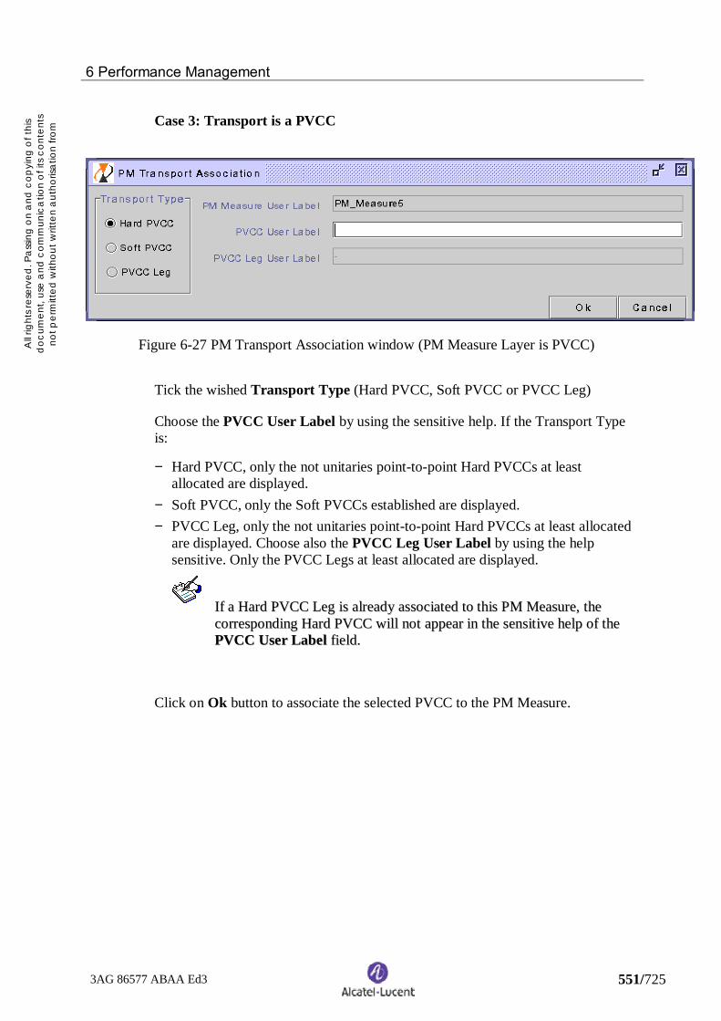
6 Performance Management
3AG 86577 ABAA Ed3 551/725
All r
ight
s res
erve
d. P
ass
ing
on
and
cop
ying
of t
his
doc
umen
t, us
e a
nd c
omm
unic
atio
n of
its
cont
ents
not p
erm
itted
with
out w
ritte
n a
utho
risa
tion
from
Alc
ate
l
Case 3: Transport is a PVCC
Figure 6-27 PM Transport Association window (PM Measure Layer is PVCC)
Tick the wished Transport Type (Hard PVCC, Soft PVCC or PVCC Leg)
Choose the PVCC User Label by using the sensitive help. If the Transport Typeis:
− Hard PVCC, only the not unitaries point-to-point Hard PVCCs at leastallocated are displayed.
− Soft PVCC, only the Soft PVCCs established are displayed.− PVCC Leg, only the not unitaries point-to-point Hard PVCCs at least allocated
are displayed. Choose also the PVCC Leg User Label by using the helpsensitive. Only the PVCC Legs at least allocated are displayed.
IIff aa HHaarrdd PPVVCCCC LLeegg iiss aallrreeaaddyy aassssoocciiaatteedd ttoo tthhiiss PPMM MMeeaassuurree,, tthheeccoorrrreessppoonnddiinngg HHaarrdd PPVVCCCC wwiillll nnoott aappppeeaarr iinn tthhee sseennssiittiivvee hheellpp ooff tthheePPVVCCCC UUsseerr LLaabbeell ffiieelldd..
Click on Ok button to associate the selected PVCC to the PM Measure.

6 Performance Management
3AG 86577 ABAA Ed3 552/725
All r
ight
s res
erve
d. P
ass
ing
on
and
cop
ying
of t
his
doc
umen
t, us
e a
nd c
omm
unic
atio
n of
its
cont
ents
not p
erm
itted
with
out w
ritte
n a
utho
risa
tion
from
Alc
ate
l
Case 4: Transport is a PVC
Figure 6-28 PM Transport Association window (PM Measure Layer is PVC)
Tick the wished Transport Type (Hard PVPC or PVCC, Soft PVPC or PVCC,PVPC or PVCC Leg)
Choose the PVC User Label by using the sensitive help. If the Transport Type is:
− Hard PVPC, only the not unitaries point-to-point Hard PVPCs at least allocatedare displayed.
− Hard PVCC, only the not unitaries point-to-point Hard PVCCs at leastallocated are displayed.
− Soft PVPC, only the Soft PVPCs established are displayed.− Soft PVCC, only the Soft PVCCs established are displayed.− PVPC Leg, only the not unitaries point-to-point Hard PVPCs at least allocated
are displayed. Choose also the PVC Leg User Label by using the helpsensitive. Only the PVC Legs at least allocated are displayed.
− PVCC Leg, only the not unitaries point-to-point Hard PVCCs at least allocatedare displayed. Choose also the PVC Leg User Label by using the helpsensitive. Only the PVC Legs at least allocated are displayed.
Click on Ok button to associate the selected PVC to the PM Measure.
For all the cases, when all operations are finished, the transport is associated to thePM Measure and the following state are updated:
− PM Measure operational state : Enabled− PM Transport state : takes the same value as the PM Measure
tate (Planned or Stopped)
The PM Measure List and PM Transport List are updated too.

6 Performance Management
3AG 86577 ABAA Ed3 553/725
All r
ight
s res
erve
d. P
ass
ing
on
and
cop
ying
of t
his
doc
umen
t, us
e a
nd c
omm
unic
atio
n of
its
cont
ents
not p
erm
itted
with
out w
ritte
n a
utho
risa
tion
from
Alc
ate
l
6.2.12.2 Dissociate a PM Transport
This function consists in dissociating PM Transports from a PM Measure.
-- TThhee OOppeerraattiioonnaall ssttaattee ooff tthhee PPMM MMeeaassuurree mmuusstt bbee EEnnaabblleedd ((ii..ee.. tthhee PPMMMMeeaassuurree oowwnnss aatt lleeaasstt oonnee PPMM TTrraannssppoorrtt))..
-- TThhee PPMM TTrraannssppoorrtt ssttaattee mmuusstt nnoott bbee DDeelleetteedd ((ii..ee aa ddeelleettiioonn rreeqquueesstt iiss aallrreeaaddyyoonn ggooiinngg))..
FFrroomm tthhee MMaaiinn vviieeww,, mmeennuu:: PPeerrffoorrmmaannccee ==>> PPMM MMeeaassuurree ==>> sseelleecctt oonnee PPMMMMeeaassuurree iinn tthhee lliisstt ==>> PPMM TTrraannssppoorrtt LLiisstt ==>> sseelleecctt oonnee oorr mmoorree PPMM TTrraannssppoorrttssiinn tthhee lliisstt ==>> DDiissssoocciiaattee
A confirmation box is displayed.
Figure 6-29 Confirmation box for dissociate one PM Transport
Figure 6-30 Confirmation box for dissociate several PM Transports
After confirmation, if the PM Measure state of the PM Measure is in Active, thedissociation is accepted and the PM is stopped on the selected PM Transport(s).
The PM Transport state becomes Deleted until 1354 BM received all the stoppedcounter notifications.
The PM Transport(s) (and all associated PPs) is (are) deleted from the PMMeasure. All the archived counters of the involved PPs are removed from thedatabase (i.e. history of PM counters are lost).
Then, the PM Transport(s) is (are) removed from the PM Transport List.A dissociated PM Transport is still considered to be associated with a measureuntil all stopped counter notifications have been received correctly.

6 Performance Management
3AG 86577 ABAA Ed3 554/725
All r
ight
s res
erve
d. P
ass
ing
on
and
cop
ying
of t
his
doc
umen
t, us
e a
nd c
omm
unic
atio
n of
its
cont
ents
not p
erm
itted
with
out w
ritte
n a
utho
risa
tion
from
Alc
ate
l
6.2.13 Display the PP List
For a selected PM Measure and PM Transport, this list presents all theperformance points (including those by default) which can be associated to a PMTransport.
The content of the displayed PP List depends on the PM Transport Type of thePM Measure.
FFrroomm tthhee MMaaiinn vviieeww,, mmeennuu:: PPeerrffoorrmmaannccee ==>> PPMM MMeeaassuurree ==>> sseelleecctt oonnee PPMMMMeeaassuurree iinn tthhee lliisstt ==>> PPMM TTrraannssppoorrtt LLiisstt ==>> sseelleecctt oonnee PPMM TTrraannssppoorrtt iinn tthhee lliisstt==>> PPPP LLiisstt
Figure 6-31 PP List for a PM measure with Transport Type = Transmission Path (between twoNEs)
NNoo ccoommmmaanndd iiss aavvaaiillaabbllee ffrroomm tthhiiss pprreevviioouuss lliisstt..
Figure 6-32 PP List for a PM measure with Transport Type = HardPVPC

6 Performance Management
3AG 86577 ABAA Ed3 555/725
All r
ight
s res
erve
d. P
ass
ing
on
and
cop
ying
of t
his
doc
umen
t, us
e a
nd c
omm
unic
atio
n of
its
cont
ents
not p
erm
itted
with
out w
ritte
n a
utho
risa
tion
from
Alc
ate
l
Figure 6-33 PP List for a PM measure with Transport Type = Hard PVCC
The attributes displayed for each PM Measure in PP List are:
− NE User Label− Termination Id.− VPI ("-"value if not significant)− VCI ("-"value if not significant)− Type (Tpvpa, pc, vc)− OAM Direction− Activity State− PP State (Planned, Active, Stopped, Stand-by)− Consistency State (Consistent, Not consistent)− Default PP (True, False)− Association State (Associated, Dissociated)
For column description, refer to chapter Error! Reference source not found..
SSoorrtt bbyy cclliicckkiinngg oonn tthhee ccoolluummnn hheeaaddeerr tthhaatt yyoouu wwaanntt ttoo ssoorrtt..
The sorting criterion is as follows:
− NE User Label− Association State

6 Performance Management
3AG 86577 ABAA Ed3 556/725
All r
ight
s res
erve
d. P
ass
ing
on
and
cop
ying
of t
his
doc
umen
t, us
e a
nd c
omm
unic
atio
n of
its
cont
ents
not p
erm
itted
with
out w
ritte
n a
utho
risa
tion
from
Alc
ate
l
FFiilltteerr bbyy cclliicckkiinngg oonn SSeeaarrcchh iinn tthhee ttoooollbbaarr..
TThhiiss ffuunnccttiioonn iiss aavvaaiillaabbllee oonnllyy wwiitthh nnoo sseelleeccttiioonn iinn tthhee lliisstt.. FFoorr ddee--sseelleeccttiioonnccoommmmaanndd,, rreeffeerr ttoo §§ 22..11..44..
Figure 6-34 PP Search window
Enter the chosen filtering criteria then click on Ok.
FFrroomm tthhee PPPP LLiisstt wwiinnddooww,, yyoouu ccaann::
Associate, refer to § 6.2.13.1
Dissociate, refer to § 6.2.13.2

6 Performance Management
3AG 86577 ABAA Ed3 557/725
All r
ight
s res
erve
d. P
ass
ing
on
and
cop
ying
of t
his
doc
umen
t, us
e a
nd c
omm
unic
atio
n of
its
cont
ents
not p
erm
itted
with
out w
ritte
n a
utho
risa
tion
from
Alc
ate
l
6.2.13.1 Associate a PP to a PM transport
This function consists in association of one or several Performance Points (PPs) toa PM Transport.
-- TThhiiss ffuunnccttiioonn iiss nnoott aapppplliiccaabbllee ttoo aa PPMM MMeeaassuurree wwiitthh TTrraannssmmiissssiioonn PPaatthh llaayyeerr,,bbeeccaauussee TTPP//VVPP__AAss aarree ddeeffaauulltt PPPPss ((ii..ee.. tthheeyy aarree aallwwaayyss aassssoocciiaatteedd ttoo tthhee PPMMTTrraannssppoorrtt bbyy ddeeffaauulltt))..
-- NNoo ooppeerraattiioonn iinn pprrooggrreessss oonn tthhee PPMM MMeeaassuurree.. AAccttiivviittyy ssttaattee ooff tthhee PPMMMMeeaassuurree mmuusstt bbee NNoonnee..
-- TThhee PPMM ttrraannssppoorrtt ssttaattee ooff tthhee sseelleecctteedd PPMM ttrraannssppoorrtt mmuusstt nnoott bbee DDeelleetteedd ((ii..ee..iinn aa ddeelleettiinngg ((ffrroomm aa PPMM MMeeaassuurree)) pphhaassee))..
FFrroomm tthhee MMaaiinn vviieeww,, mmeennuu:: PPeerrffoorrmmaannccee ==>> PPMM MMeeaassuurree ==>> sseelleecctt oonnee PPMMMMeeaassuurree iinn tthhee lliisstt ==>> PPMM TTrraannssppoorrtt LLiisstt ==>> sseelleecctt oonnee PPMM ttrraannssppoorrtt iinn tthhee lliisstt==>> PPPP LLiisstt ==>> sseelleecctt oonnee oorr mmoorree PPPPss iinn tthhee lliisstt ==>> AAssssoocciiaattee
Figure 6-35 Confirmation box for associate one PP to a PM transport
Figure 6-36 Confirmation box for associate several PP to a PM transport
After confirmation, the PP(s) is (are) associated to the PM Transport.
The operation is allowed even if the PM Measure is in the Active PM Measurestate. In this case, the PM counters are implicitly started on the new PP.
The PP State of the PP(s) takes the same value as the PM Transport State(Planned, Active, Stopped or Stand-by).

6 Performance Management
3AG 86577 ABAA Ed3 558/725
All r
ight
s res
erve
d. P
ass
ing
on
and
cop
ying
of t
his
doc
umen
t, us
e a
nd c
omm
unic
atio
n of
its
cont
ents
not p
erm
itted
with
out w
ritte
n a
utho
risa
tion
from
Alc
ate
l
6.2.13.2 Dissociate a PP from a PM transport
This function allows to the operator to dissociate one or several PerformancePoints (PPs) to a PM Transport.
-- TThhiiss ffuunnccttiioonn iiss nnoott aapppplliiccaabbllee ttoo aa PPMM MMeeaassuurree wwiitthh TTrraannssmmiissssiioonn PPaatthh llaayyeerr,,bbeeccaauussee TTPP//VVPP__AAss aarree ddeeffaauulltt PPPPss ((ii..ee.. tthheeyy aarree aallwwaayyss aassssoocciiaatteedd ttoo tthhee PPMMTTrraannssppoorrtt bbyy ddeeffaauulltt))..
-- TThhee PPPP mmuusstt bbee aassssoocciiaatteedd ttoo tthhee PPMM ttrraannssppoorrtt..
-- TThhee PPPP mmuusstt nnoott bbee aa ddeeffaauulltt PPPP..
-- NNoo ooppeerraattiioonn iinn pprrooggrreessss oonn tthhee PPMM MMeeaassuurree.. AAccttiivviittyy ssttaattee ooff tthhee PPMMMMeeaassuurree mmuusstt bbee NNoonnee aanndd PPMM MMeeaassuurree ssttaattee iiss nnoott aaccttiivvee..
FFrroomm tthhee MMaaiinn vviieeww,, mmeennuu:: PPeerrffoorrmmaannccee ==>> PPMM MMeeaassuurree ==>> sseelleecctt oonnee PPMMMMeeaassuurree iinn tthhee lliisstt ==>> PPMM TTrraannssppoorrtt LLiisstt ==>> sseelleecctt oonnee PPMM ttrraannssppoorrtt iinn tthhee lliisstt==>> PPPP LLiisstt ==>> sseelleecctt oonnee oorr mmoorree PPPPss iinn tthhee lliisstt ==>> DDiissssoocciiaattee
Figure 6-37 Confirmation box for dissociate one PP from a PM transport
Figure 6-38 Confirmation box for dissociate several PP from a PM transport
After confirmation, the PP(s) is (are) dissociated from the PM Transport.
The PP State of the PP(s) takes the same value as the PM Transport State(Planned, Active, Stopped or Stand-by).

6 Performance Management
3AG 86577 ABAA Ed3 559/725
All r
ight
s res
erve
d. P
ass
ing
on
and
cop
ying
of t
his
doc
umen
t, us
e a
nd c
omm
unic
atio
n of
its
cont
ents
not p
erm
itted
with
out w
ritte
n a
utho
risa
tion
from
Alc
ate
l
6.3 Managing Periodic Report Profiles
Periodic Report Profiles allow to generate automatically some PM results inperiodic report on different outputs (printer, file and mail).
These Periodic Report Profiles are created from the 1354 BM application, and theperiodic generation of the reports (related to these profiles) is provided by thecomponent PMDS.
The following PM Periodic Report Profiles are managed:
− Periodic Counters reports: they contain collected information on counters.− Periodic Parameters (Ratios) reports: they contain ratios computed with
collected counters. (*)− Periodic Threshold Counters reports: they contain collected information on
counters that exceed some user’s defined thresholds.− Periodic Threshold Parameters (Ratios) reports: they contain ratios computed
with collected counters, exceeding some user’s defined thresholds. (*)− Periodic Transport State reports: they contain state transitions history during
the observation period. The 1354 BM will handle provisioning state(Allocated, Implemented and Commissioned) and availability status (Normal,Degraded and In Failure).
(*) Not available in R7.

6 Performance Management
3AG 86577 ABAA Ed3 560/725
All r
ight
s res
erve
d. P
ass
ing
on
and
cop
ying
of t
his
doc
umen
t, us
e a
nd c
omm
unic
atio
n of
its
cont
ents
not p
erm
itted
with
out w
ritte
n a
utho
risa
tion
from
Alc
ate
l
6.3.1 Display the Periodic Report Profile list
The Periodic Report Profile List window presents all the reports profiles and theirattributes.
FFrroomm tthhee MMaaiinn vviieeww,, mmeennuu:: PPeerrffoorrmmaannccee ==>> PPeerriiooddiicc RReeppoorrtt PPrrooffiillee
Figure 6-39 Periodic Report Profile List window
The attributes displayed for each Periodic Report Profile List are:
− User Label− Frequency− Kind− Operational State− Active State− Layer− GranularityFor column description, refer to chapter Error! Reference source not found..
SSoorrtt bbyy cclliicckkiinngg oonn tthhee ccoolluummnn hheeaaddeerr tthhaatt yyoouu wwaanntt ttoo ssoorrtt..
The sorting criterion is as follows:
− User Label

6 Performance Management
3AG 86577 ABAA Ed3 561/725
All r
ight
s res
erve
d. P
ass
ing
on
and
cop
ying
of t
his
doc
umen
t, us
e a
nd c
omm
unic
atio
n of
its
cont
ents
not p
erm
itted
with
out w
ritte
n a
utho
risa
tion
from
Alc
ate
l
FFiilltteerr bbyy cclliicckkiinngg oonn SSeeaarrcchh iinn tthhee ttoooollbbaarr..
Figure 6-40 Periodic Report Profile Search window
Enter the chosen filtering criteria then click on Ok.
FFrroomm tthhee PPeerriiooddiicc RReeppoorrtt PPrrooffiillee LLiisstt wwiinnddooww,, yyoouu ccaann::
Create a Periodic Report Profile, refer to § 6.3.2
Modify a Periodic Report Profile, refer to § 6.3.3
Delete a Periodic Report Profile, refer to § 6.3.4
Display the Periodic Report Profile properties, refer to § 6.3.5

6 Performance Management
3AG 86577 ABAA Ed3 562/725
All r
ight
s res
erve
d. P
ass
ing
on
and
cop
ying
of t
his
doc
umen
t, us
e a
nd c
omm
unic
atio
n of
its
cont
ents
not p
erm
itted
with
out w
ritte
n a
utho
risa
tion
from
Alc
ate
l
6.3.2 Create a Periodic Report Profile
This function allows to define Periodic Report Profile of performance counters(based on thresholds or not) or Transport state. These periodic report profilesallow to generate PM results in periodic reports.
FFrroomm tthhee MMaaiinn vviieeww,, mmeennuu:: PPeerrffoorrmmaannccee ==>> PPeerriiooddiicc RReeppoorrtt PPrrooffiillee ==>>CCrreeaattee
TThhiiss ffuunnccttiioonn iiss aavvaaiillaabbllee oonnllyy wwiitthh nnoo sseelleeccttiioonn iinn tthhee lliisstt.. FFoorr ddee--sseelleeccttiioonnccoommmmaanndd,, rreeffeerr ttoo §§ 22..11..44..
Figure 6-41 Periodic Report Profile creation window (Report Kind =Counter)
To create a Periodic Report Profile:
− Enter a Periodic Report Profile User Label− Enter a Comment (optional)− In the Characteristics area, choose the Report Kind (Counter, Counter
Threshold or Transport state)
Following the Report Kind selected, the fields to be entered are not the same, seehereafter the different proposed windows:

6 Performance Management
3AG 86577 ABAA Ed3 563/725
All r
ight
s res
erve
d. P
ass
ing
on
and
cop
ying
of t
his
doc
umen
t, us
e a
nd c
omm
unic
atio
n of
its
cont
ents
not p
erm
itted
with
out w
ritte
n a
utho
risa
tion
from
Alc
ate
l
Figure 6-42 Periodic Report Profile creation window (Report Kind = Transport State)
Figure 6-43 Periodic Report Profile creation window (Report Kind = CounterThreshold)

6 Performance Management
3AG 86577 ABAA Ed3 564/725
All r
ight
s res
erve
d. P
ass
ing
on
and
cop
ying
of t
his
doc
umen
t, us
e a
nd c
omm
unic
atio
n of
its
cont
ents
not p
erm
itted
with
out w
ritte
n a
utho
risa
tion
from
Alc
ate
l
− If Transport State value is selected in Report Kind field, choose the StateReport Type. This option allows to get periodic report on transport statetransition based on Provisioning State, Availability Status or both.
− Choose the PM Layer (Transmission Path, PVPC, PVCC, PVC (=PVPC &PVCC))
− Choose the Granularity (15 Min or 24 H)− Choose the PM Frequency (depends of the choosen granularity value).
Frequency of a periodic report must be equal or greater than the value of thegranularity, so that the report contains information of at least one period.
Granularity Frequency
15 Min 15 Min / 1 Hour / 2 Hours / 1 Day
24 H 1 Day / 1 Week / 1 Month / 2 Months / 1 Year
− Choose the Output Type (mail, printer or file)− Choose the Output Name (mail address, printer name or file name)− Enter the PM Threshold Values (if the choosen Report Kind is Counter
Threshold)
Click on Ok.
The Periodic Report Profile is created with the following states:
− operational state : Disabled (= no associated PM Measure)− active state : None
The Periodic Report Profile List is updated too.

6 Performance Management
3AG 86577 ABAA Ed3 565/725
All r
ight
s res
erve
d. P
ass
ing
on
and
cop
ying
of t
his
doc
umen
t, us
e a
nd c
omm
unic
atio
n of
its
cont
ents
not p
erm
itted
with
out w
ritte
n a
utho
risa
tion
from
Alc
ate
l
6.3.3 Modify a Periodic Report Profile
This function consists in modifying some characteristics of a Periodic ReportProfile:
− Periodic Report Profile User Label− Comment− PM Frequency− Output Type− Output Name
-- TThhee nneeww PPeerriiooddiicc RReeppoorrtt PPrrooffiillee UUsseerr LLaabbeell mmuusstt bbee ddiiffffeerreenntt aass oonnee wwhhiicchh iissaallrreeaaddyy uusseedd bbyy aannootthheerr PPeerriiooddiicc RReeppoorrtt PPrrooffiillee..
FFrroomm tthhee MMaaiinn vviieeww,, mmeennuu:: PPeerrffoorrmmaannccee ==>> PPeerriiooddiicc RReeppoorrtt PPrrooffiillee ==>> sseelleeccttoonnee PPeerriiooddiicc RReeppoorrtt PPrrooffiillee iinn tthhee lliisstt ==>> MMooddiiffyy
TThhiiss ffuunnccttiioonn iiss aavvaaiillaabbllee oonnllyy iiff aa PPeerriiooddiicc RReeppoorrtt PPrrooffiillee iiss sseelleecctteedd..
Figure 6-44 Periodic Report Profile modification window

6 Performance Management
3AG 86577 ABAA Ed3 566/725
All r
ight
s res
erve
d. P
ass
ing
on
and
cop
ying
of t
his
doc
umen
t, us
e a
nd c
omm
unic
atio
n of
its
cont
ents
not p
erm
itted
with
out w
ritte
n a
utho
risa
tion
from
Alc
ate
l
To modify a Periodic Report Profile:
− Enter a New User Label (optional)− Change the Comment (optional)− Change the PM Frequency (optional)− Change the Output Type (optional)− Change the Output Name (optional)
If a New User Label is entered, the Periodic Report Profile List is updated.

6 Performance Management
3AG 86577 ABAA Ed3 567/725
All r
ight
s res
erve
d. P
ass
ing
on
and
cop
ying
of t
his
doc
umen
t, us
e a
nd c
omm
unic
atio
n of
its
cont
ents
not p
erm
itted
with
out w
ritte
n a
utho
risa
tion
from
Alc
ate
l
6.3.4 Delete a Periodic Report Profile
This function consists in deleting one or several Periodic Reports Profiles.
-- TThhee PPeerriiooddiicc RReeppoorrtt PPrrooffiillee mmuusstt bbee eemmppttyy ((nnoott aassssoocciiaatteedd ttoo aannyy mmeeaassuurree))..
FFrroomm tthhee MMaaiinn vviieeww,, mmeennuu:: PPeerrffoorrmmaannccee ==>> PPeerriiooddiicc RReeppoorrtt PPrrooffiillee ==>> sseelleeccttoonnee oorr sseevveerraall PPeerriiooddiicc RReeppoorrtt PPrrooffiillee iinn tthhee lliisstt ==>> DDeelleettee
TThhiiss ffuunnccttiioonn iiss aavvaaiillaabbllee oonnllyy iiff aatt lleeaasstt oonnee PPeerriiooddiicc RReeppoorrtt PPrrooffiillee iiss sseelleecctteedd..
Figure 6-45 Confirmation box for deleting one Report Profile
Figure 6-46 Confirmation box for deleting several Reports Profiles
After confirmation, the Report Profile is deleted.
The Periodic Report Profile List is updated.

6 Performance Management
3AG 86577 ABAA Ed3 568/725
All r
ight
s res
erve
d. P
ass
ing
on
and
cop
ying
of t
his
doc
umen
t, us
e a
nd c
omm
unic
atio
n of
its
cont
ents
not p
erm
itted
with
out w
ritte
n a
utho
risa
tion
from
Alc
ate
l
6.3.5 Display the Periodic Report Profile properties
This function consists in displaying information about a Periodic Report Profile.
FFrroomm tthhee MMaaiinn vviieeww,, mmeennuu:: PPeerrffoorrmmaannccee ==>> PPeerriiooddiicc RReeppoorrtt PPrrooffiillee ==>> sseelleecctt aaPPeerriiooddiicc RReeppoorrtt PPrrooffiillee iinn tthhee lliisstt ==>> PPrrooppeerrttiieess
Figure 6-47 Periodic Report Profile Properties window (Report Kind = Counter)
Figure 6-48 Periodic Report Profile Properties window (Report Kind = Transport State)

6 Performance Management
3AG 86577 ABAA Ed3 569/725
All r
ight
s res
erve
d. P
ass
ing
on
and
cop
ying
of t
his
doc
umen
t, us
e a
nd c
omm
unic
atio
n of
its
cont
ents
not p
erm
itted
with
out w
ritte
n a
utho
risa
tion
from
Alc
ate
l
Figure 6-49 Periodic Report Profile Properties window (Report Kind = Counter Threshold)

6 Performance Management
3AG 86577 ABAA Ed3 570/725
All r
ight
s res
erve
d. P
ass
ing
on
and
cop
ying
of t
his
doc
umen
t, us
e a
nd c
omm
unic
atio
n of
its
cont
ents
not p
erm
itted
with
out w
ritte
n a
utho
risa
tion
from
Alc
ate
l
6.4 Managing TCA Profiles
The thresholds of the PM Counters may be set or modified.
When a threshold is crossed, an alarm event report is sent. This alarm is calledTCA (Threshold Crossing Alarm).
For Non-OAM PM management, the TCA profiles are available only on theTP/VP_A layer.
The TCA profile defines the thresholds for each counter available at the TP/VP_Alayer, on which TCA is supported (see Figure 6-1 Available Non-OAM PMcounters, column TCA).
The ATM NE provides a set of 12 default TCA profiles (one per granularity andper bit rate).
The 1354 BM provides to the operator 12 pre-defined profiles. They areconfigured at the installation, and their content can be displayed but not modifiedor deleted.
Each TCA profile are created with the following parameters:
− TCA profile user label− PM category : NON-OAM− PM Layer : Transmission Path− Granularity : 15 Min or 24 H− Bit rate : VC4-4C, VC-4, VC-3, VC-12, 2 Mb/s, 34 Mb/s− For each counter on which TCA is settable:
− Low threshold value− High threshold value.

6 Performance Management
3AG 86577 ABAA Ed3 571/725
All r
ight
s res
erve
d. P
ass
ing
on
and
cop
ying
of t
his
doc
umen
t, us
e a
nd c
omm
unic
atio
n of
its
cont
ents
not p
erm
itted
with
out w
ritte
n a
utho
risa
tion
from
Alc
ate
l
6.4.1 Display the TCA Profile list
The TCA Profile List window presents all the TCA profiles and their attributes.
FFrroomm tthhee MMaaiinn vviieeww,, mmeennuu:: PPeerrffoorrmmaannccee ==>> TTCCAA PPrrooffiillee
Figure 6-50 TCA Profile List window
The attributes displayed for each TCA profile are:
− User Label− Granularity− Bit Rate
For column description, refer to chapter Error! Reference source not found..
SSoorrtt bbyy cclliicckkiinngg oonn tthhee ccoolluummnn hheeaaddeerr tthhaatt yyoouu wwaanntt ttoo ssoorrtt..
The sorting criteria are as follows:
− User Label− Granularity− Bit Rate
FFrroomm tthhee TTCCAA PPrrooffiillee LLiisstt wwiinnddooww,, yyoouu ccaann::
Display the TCA Profile properties, refer to § 6.4.2

6 Performance Management
3AG 86577 ABAA Ed3 572/725
All r
ight
s res
erve
d. P
ass
ing
on
and
cop
ying
of t
his
doc
umen
t, us
e a
nd c
omm
unic
atio
n of
its
cont
ents
not p
erm
itted
with
out w
ritte
n a
utho
risa
tion
from
Alc
ate
l
6.4.2 Display the TCA Profile properties
This function consists in displaying information about a TCA Profile.
FFrroomm tthhee MMaaiinn vviieeww,, mmeennuu:: PPeerrffoorrmmaannccee ==>> TTCCAA PPrrooffiillee ==>> sseelleecctt aa TTCCAAPPrrooffiillee iinn tthhee lliisstt ==>> PPrrooppeerrttiieess
Figure 6-51 TCA Profile Properties window

6 Performance Management
3AG 86577 ABAA Ed3 573/725
All r
ight
s res
erve
d. P
ass
ing
on
and
cop
ying
of t
his
doc
umen
t, us
e a
nd c
omm
unic
atio
n of
its
cont
ents
not p
erm
itted
with
out w
ritte
n a
utho
risa
tion
from
Alc
ate
l

7 Administration Management
3AG 86577 ABAA Ed3 574/725
All r
ight
s res
erve
d. P
ass
ing
on
and
cop
ying
of t
his
doc
umen
t, us
e a
nd c
omm
unic
atio
n o
f its
con
tent
sno
t per
mitt
ed w
ithou
t writ
ten
aut
horis
atio
n fro
mA
lca
tel
7 Administration management
This chapter deals with the administrationservices offered by the 1354 BM.
7.1 PNNI management
7.2 ATM traffic contract profile management
7.3 Operator profile management

7 Administration Management
3AG 86577 ABAA Ed3 575/725
All r
ight
s res
erve
d. P
ass
ing
on
and
cop
ying
of t
his
doc
umen
t, us
e a
nd c
omm
unic
atio
n o
f its
con
tent
sno
t per
mitt
ed w
ithou
t writ
ten
aut
horis
atio
n fro
mA
lca
tel
7.1 PNNI management
The PNNI management, part of the administration management, consists in:
− performing actions such as:− configuring node ATM addresses− activating / deactivating nodes− configuring interface ATM addresses
− displaying administration information such as:− NE list− NE counter observation− termination list
The PNNI management chain gives the order in which the available actions maybe performed.
Define NE
Configure PNNI nodeATM address
Configure terminationsDefine terminations
ActivatePNNI node
DeactivatePNNI node
Configure PNNI interface ATM address
Network construction(refer to chapter 3)
Figure 7-1 PNNI management chain
For managing PNNI, you can:
display the NE list for administration, refer to § 7.1.1

7 Administration Management
3AG 86577 ABAA Ed3 576/725
All r
ight
s res
erve
d. P
ass
ing
on
and
cop
ying
of t
his
doc
umen
t, us
e a
nd c
omm
unic
atio
n o
f its
con
tent
sno
t per
mitt
ed w
ithou
t writ
ten
aut
horis
atio
n fro
mA
lca
tel
7.1.1 Display the NE list for administration
The NE List (Administration) window presents all the NEs managed (i.e. alreadydefined) by the 1354 BM, and their attributes.
FFrroomm tthhee MMaaiinn vviieeww,, mmeennuu:: AAddmmiinniissttrraattiioonn ==>> PPNNNNII
Figure 7-2 NE List (Administration) window
The attributes displayed for each NE are:
− User Label− Parent Sub-network User Label− Type− Version− ATM Address− PNNI Node State
For column description, refer to chapter 9.

7 Administration Management
3AG 86577 ABAA Ed3 577/725
All r
ight
s res
erve
d. P
ass
ing
on
and
cop
ying
of t
his
doc
umen
t, us
e a
nd c
omm
unic
atio
n o
f its
con
tent
sno
t per
mitt
ed w
ithou
t writ
ten
aut
horis
atio
n fro
mA
lca
tel
SSoorrtt bbyy cclliicckkiinngg oonn tthhee ccoolluummnn hheeaaddeerr tthhaatt yyoouu wwaanntt ttoo ssoorrtt..
The sorting criteria are as follows:
− User Label− Parent Sub-network User Label
FFiilltteerr bbyy cclliicckkiinngg oonn SSeeaarrcchh iinn tthhee ttoooollbbaarr..
TThhiiss ffuunnccttiioonn iiss aavvaaiillaabbllee oonnllyy wwiitthh nnoo sseelleeccttiioonn iinn tthhee lliisstt.. FFoorr ddee--sseelleeccttiioonnccoommmmaanndd,, rreeffeerr ttoo §§ 22..11..44..
Figure 7-3 NE Search (Administration) window
Enter the chosen filtering criteria then click on Ok.
FFrroomm tthhee NNEE LLiisstt ((AAddmmiinniissttrraattiioonn)) wwiinnddooww,, yyoouu ccaann::
observe a NE, refer to § 7.1.2
configure the PNNI node ATM address, refer to § 7.1.3
activate a PNNI node, refer to § 7.1.4
deactivate a PNNI node, refer to § 7.1.5
display the termination list for administration, refer to § 7.1.6

7 Administration Management
3AG 86577 ABAA Ed3 578/725
All r
ight
s res
erve
d. P
ass
ing
on
and
cop
ying
of t
his
doc
umen
t, us
e a
nd c
omm
unic
atio
n o
f its
con
tent
sno
t per
mitt
ed w
ithou
t writ
ten
aut
horis
atio
n fro
mA
lca
tel
7.1.2 Observe a NE
This function consists in getting information about a NE in order to administer it.
FFrroomm tthhee MMaaiinn vviieeww,, mmeennuu:: AAddmmiinniissttrraattiioonn ==>> PPNNNNII ==>> sseelleecctt aann NNEE iinn tthhee lliisstt==>> OObbsseerrvvee
Figure 7-4 NE Observation window
The last four fields give the states of NE counters that have been retrieved duringthe last upload (whose date is also displayed). They allow the user to know howmany hard or soft connections can still be used.
The Maximum Connections value includes PVPC/PVCC cross-connections andend-connections.
TThhee mmaaxxiimmuumm nnuummbbeerr ooff hhaarrdd ccoonnnneeccttiioonnss iiss eeqquuaall ttoo tthhee MMaaxxiimmuumm CCoonnnneeccttiioonnssvvaalluuee mmiinnuuss tthhee MMaaxxiimmuumm SSoofftt CCoonnnneeccttiioonnss vvaalluuee..
The Maximum Soft Connections value by default is null. To modify it:
− Enter a new value.− Click on Ok.

7 Administration Management
3AG 86577 ABAA Ed3 579/725
All r
ight
s res
erve
d. P
ass
ing
on
and
cop
ying
of t
his
doc
umen
t, us
e a
nd c
omm
unic
atio
n o
f its
con
tent
sno
t per
mitt
ed w
ithou
t writ
ten
aut
horis
atio
n fro
mA
lca
tel
7.1.3 Configure the PNNI node ATM address
This function consists in giving an ATM address to a NE, so that it can be used asa PNNI node by soft PVCs, after being activated (refer to § 7.1.4).
-- TThhee PPNNNNII nnooddee ssttaattee ooff tthhee NNEE mmuusstt bbee DDiissaabblleedd..
-- AAccttiivviittyy ssttaattee ooff tthhee NNEE mmuusstt bbee NNoonnee ((== nnoo aauuddiitt//aalliiggnnmmeenntt oorrssyynncchhrroonniissaattiioonn wwiitthh 11335544 RRMM iinn pprrooggrreessss oonn tthhiiss NNEE))..
FFrroomm tthhee MMaaiinn vviieeww,, mmeennuu:: AAddmmiinniissttrraattiioonn ==>> PPNNNNII ==>> sseelleecctt aann NNEE iinn tthhee lliisstt==>> CCoonnffiigguurree
Figure 7-5 PNNI Node ATM Address Configuration window
To configure the PNNI node ATM address:
− Enter the ATM Address: two formats are available (DCC/ICD, Generic).− Click on Ok.The NE is dedicated to the PNNI management.
The NE List (Administration) window is updated.
Once the PNNI node ATM address is configured, do not forget to activate thePNNI node (refer to § 7.1.4) so that it can be used by soft PVCs.

7 Administration Management
3AG 86577 ABAA Ed3 580/725
All r
ight
s res
erve
d. P
ass
ing
on
and
cop
ying
of t
his
doc
umen
t, us
e a
nd c
omm
unic
atio
n o
f its
con
tent
sno
t per
mitt
ed w
ithou
t writ
ten
aut
horis
atio
n fro
mA
lca
tel
7.1.4 Activate a PNNI node
This function consists in enabling a PNNI node to be used by soft PVCs.
-- TThhee PPNNNNII nnooddee ssttaattee ooff tthhee NNEE mmuusstt bbee DDiissaabblleedd..
-- TThhee PPNNNNII nnooddee AATTMM aaddddrreessss mmuusstt bbee ccoonnffiigguurreedd..
-- AAccttiivviittyy ssttaattee ooff tthhee NNEE mmuusstt bbee NNoonnee ((== nnoo aauuddiitt//aalliiggnnmmeenntt oorrssyynncchhrroonniissaattiioonn wwiitthh 11335544 RRMM iinn pprrooggrreessss oonn tthhiiss NNEE))..
FFrroomm tthhee MMaaiinn vviieeww,, mmeennuu:: AAddmmiinniissttrraattiioonn ==>> PPNNNNII ==>> sseelleecctt oonnee oorr sseevveerraallNNEEss iinn tthhee lliisstt ==>> AAccttiivvaattee
A confirmation box is displayed:
Figure 7-6 Confirmation box for activating one PNNI node
Figure 7-7 Confirmation box for activating several PNNI nodes
After confirmation, the PNNI nodes are activated.
Their PNNI node states change to Enabled.
The NE List (Administration) window is updated.

7 Administration Management
3AG 86577 ABAA Ed3 581/725
All r
ight
s res
erve
d. P
ass
ing
on
and
cop
ying
of t
his
doc
umen
t, us
e a
nd c
omm
unic
atio
n o
f its
con
tent
sno
t per
mitt
ed w
ithou
t writ
ten
aut
horis
atio
n fro
mA
lca
tel
7.1.5 Deactivate a PNNI node
This function consists in deactivating a previously activated PNNI node.
-- TThhee PPNNNNII nnooddee ssttaattee ooff tthhee NNEE mmuusstt bbee EEnnaabblleedd..
-- AAccttiivviittyy ssttaattee ooff tthhee NNEE mmuusstt bbee NNoonnee ((== nnoo aauuddiitt//aalliiggnnmmeenntt oorrssyynncchhrroonniissaattiioonn wwiitthh 11335544 RRMM iinn pprrooggrreessss oonn tthhiiss NNEE))..
FFrroomm tthhee MMaaiinn vviieeww,, mmeennuu:: AAddmmiinniissttrraattiioonn ==>> PPNNNNII ==>> sseelleecctt oonnee oorr sseevveerraallNNEEss iinn tthhee lliisstt ==>> DDeeaaccttiivvaattee
A confirmation box is displayed:
Figure 7-8 Confirmation box for deactivating one PNNI node
Figure 7-9 Confirmation box for deactivating several PNNI nodes
After confirmation, the PNNI nodes are deactivated.
Their PNNI node states change to Disabled.
The NE List (Administration and Construction) windows are updated.
Now, the PNNI node ATM addresses can be modified (refer to §7.1.2).

7 Administration Management
3AG 86577 ABAA Ed3 582/725
All r
ight
s res
erve
d. P
ass
ing
on
and
cop
ying
of t
his
doc
umen
t, us
e a
nd c
omm
unic
atio
n o
f its
con
tent
sno
t per
mitt
ed w
ithou
t writ
ten
aut
horis
atio
n fro
mA
lca
tel
7.1.6 Display the termination list for administration
The Terminations List (Administration) window presents all the NE terminationsand their attributes.
FFrroomm tthhee MMaaiinn vviieeww,, mmeennuu:: AAddmmiinniissttrraattiioonn ==>> PPNNNNII ==>> sseelleecctt aann NNEE iinn tthhee lliisstt==>> TTeerrmm.. LLiisstt
Figure 7-10 Termination List (Administration) window
The attributes displayed for each termination are:
− Id.− Technology− Bit Rate− ATM address
For column description, refer to chapter 9.
SSoorrtt bbyy cclliicckkiinngg oonn tthhee ccoolluummnn hheeaaddeerr tthhaatt yyoouu wwaanntt ttoo ssoorrtt..
The sorting criteria are as follows:

7 Administration Management
3AG 86577 ABAA Ed3 583/725
All r
ight
s res
erve
d. P
ass
ing
on
and
cop
ying
of t
his
doc
umen
t, us
e a
nd c
omm
unic
atio
n o
f its
con
tent
sno
t per
mitt
ed w
ithou
t writ
ten
aut
horis
atio
n fro
mA
lca
tel
− Id.− Technology
FFiilltteerr bbyy cclliicckkiinngg oonn SSeeaarrcchh iinn tthhee ttoooollbbaarr..
TThhiiss ffuunnccttiioonn iiss aavvaaiillaabbllee oonnllyy wwiitthh nnoo sseelleeccttiioonn iinn tthhee lliisstt.. FFoorr ddee--sseelleeccttiioonnccoommmmaanndd,, rreeffeerr ttoo §§ 22..11..44..
Figure 7-11 Termination Search (Administration) window
Enter the chosen filtering criteria then click on Ok.
FFrroomm tthhee TTeerrmmiinnaattiioonn LLiisstt ((AAddmmiinniissttrraattiioonn)) wwiinnddooww,, yyoouu ccaann::
configure the PNNI interface ATM address, refer to § 7.1.7

7 Administration Management
3AG 86577 ABAA Ed3 584/725
All r
ight
s res
erve
d. P
ass
ing
on
and
cop
ying
of t
his
doc
umen
t, us
e a
nd c
omm
unic
atio
n o
f its
con
tent
sno
t per
mitt
ed w
ithou
t writ
ten
aut
horis
atio
n fro
mA
lca
tel
7.1.7 Configure the PNNI interface ATM address
This function consists in giving an ATM address to a termination, so that softPVCs can use it as a PNNI interface.
-- TThhee tteerrmmiinnaattiioonn mmuusstt bbee ddeeffiinneedd ((oorr ccoonnffiigguurreedd iiff iitt iiss nnoott mmaannaaggeedd bbyy tthheeRRMM))..
-- AAccttiivviittyy ssttaattee ooff tthhee NNEE mmuusstt bbee NNoonnee ((== nnoo aauuddiitt//aalliiggnnmmeenntt oorrssyynncchhrroonniissaattiioonn wwiitthh 11335544 RRMM iinn pprrooggrreessss oonn tthhiiss NNEE))..
FFrroomm tthhee MMaaiinn vviieeww,, mmeennuu:: AAddmmiinniissttrraattiioonn ==>> PPNNNNII ==>> sseelleecctt aann NNEE iinn tthhee lliisstt==>> TTeerrmm.. LLiisstt ==>> sseelleecctt aa tteerrmmiinnaattiioonn iinn tthhee lliisstt ==>> CCoonnffiigguurree
Figure 7-12 PNNI Interface ATM Address Configuration window
To configure the PNNI interface ATM address:
− Enter the ATM Address on twenty bytes (last byte corresponding to selectormust be equal to ‘00’).Three formats are available (DCC, ICD, E.164) (see the Figure 7-13 Threeways of encoding ATM Address)
− Click on Ok.

7 Administration Management
3AG 86577 ABAA Ed3 585/725
All r
ight
s res
erve
d. P
ass
ing
on
and
cop
ying
of t
his
doc
umen
t, us
e a
nd c
omm
unic
atio
n o
f its
con
tent
sno
t per
mitt
ed w
ithou
t writ
ten
aut
horis
atio
n fro
mA
lca
tel
Figure 7-13 Three ways of encoding ATM Address
Then, the NE is dedicated to the PNNI management.
The Termination List (Administration and Construction) windows are updated.
OOnnccee tthhee PPNNNNII iinntteerrffaaccee AATTMM aaddddrreessss iiss ccoonnffiigguurreedd,, ddoo nnoott ffoorrggeett ttoo aaccttiivvaattee aaPPNNNNII nnooddee ssoo tthhaatt iitt ccaann bbee uusseedd bbyy ssoofftt PPVVCC..
TThhee ccoonnffiigguurraattiioonn wwiitthh aann eemmppttyy AATTMM aaddddrreessss wwiillll rreemmoovvee tthhee AATTMM aaddddrreessssaassssoocciiaatteedd ttoo tthhee tteerrmmiinnaattiioonn..

7 Administration Management
3AG 86577 ABAA Ed3 586/725
All r
ight
s res
erve
d. P
ass
ing
on
and
cop
ying
of t
his
doc
umen
t, us
e a
nd c
omm
unic
atio
n o
f its
con
tent
sno
t per
mitt
ed w
ithou
t writ
ten
aut
horis
atio
n fro
mA
lca
tel
7.2 ATM traffic management
The management of the ATM traffic is divided into two parts:
− the traffic descriptor management− the traffic profile managementThe traffic descriptors are applied to a traffic contract type and the associatedtraffic parameters that have been negotiated.
A traffic profile is defined by:
− a service type and its associated description− transmission mode parameters (direction, allocation type, re-routing)− traffic descriptorsTraffic profiles are useful to simplify the PVC designing operations by hiding thetraffic descriptor aspect.
In the equipment, the traffic descriptors of the connections are associated to anindex. This index will be known by the 1354 BM and used like reference of trafficdescriptors.
The number of traffic descriptors is limited in the equipment (refer to § 10.1).
Because of this limitation, the number of traffic descriptors is limited in theprofile management (limitation defined by a configurable value).
AAss tthhee ttrraaffffiicc pprrooffiillee wwiillll bbee aabbllee ttoo bbee uusseedd ffoorr tthhee hhaarrdd aanndd ssoofftt PPVVCC ddeeffiinniittiioonn,,tthhee iinnffoorrmmaattiioonn lliikkee aallllooccaattiioonn ttyyppee wwiillll nnoott bbee ddeeffiinneedd aatt tthhee ccrreeaattiioonn ooff tthhee ttrraaffffiiccpprrooffiillee bbuutt aatt tthhee PPVVCC ddeeffiinniittiioonn..
11335544 BBMM aapppplliiccaattiioonn pprroovviiddeess pprree--ffiixxeedd ttrraaffffiicc ddeessccrriippttoorrss aanndd ttrraaffffiicc pprrooffiilleess..
7.2.1 Traffic descriptor management
The traffic descriptor management allows the user to create, modify and deletetraffic descriptors.
AAss lloonngg aass aa ttrraaffffiicc ddeessccrriippttoorr iiss uusseedd bbyy aatt lleeaasstt oonnee PPVVCC,, iitt ccaannnnoott bbee ddeelleetteedd..
At the 1354 BM installation, some traffic descriptors are pre-defined in itsdatabase.

7 Administration Management
3AG 86577 ABAA Ed3 587/725
All r
ight
s res
erve
d. P
ass
ing
on
and
cop
ying
of t
his
doc
umen
t, us
e a
nd c
omm
unic
atio
n o
f its
con
tent
sno
t per
mitt
ed w
ithou
t writ
ten
aut
horis
atio
n fro
mA
lca
tel
They can be modified or deleted (excepted that contains any characteristic (noPCR, no MCR, no CDVT …), not frame based and used by the specific trafficprofile which allows to define a flexible unitary hard PVPC).
For managing traffic descriptors, you can:
display the traffic descriptor list, refer to § 7.2.1.1

7 Administration Management
3AG 86577 ABAA Ed3 588/725
All r
ight
s res
erve
d. P
ass
ing
on
and
cop
ying
of t
his
doc
umen
t, us
e a
nd c
omm
unic
atio
n o
f its
con
tent
sno
t per
mitt
ed w
ithou
t writ
ten
aut
horis
atio
n fro
mA
lca
tel
7.2.1.1 Display the traffic descriptor list
The Traffic Descriptor List window presents all the traffic descriptors and theirattributes.
FFrroomm tthhee MMaaiinn vviieeww,, mmeennuu:: AAddmmiinniissttrraattiioonn ==>> TTrraaffffiicc ==>> TTrraaffffiicc ddeessccrriippttoorrss
Figure 7-14 Traffic Descriptor List window
The attributes displayed for each traffic descriptor are:
− User Label− Comment− Traffic Contract− PCR− CDVT PCR− MCR− CDVT MCR− MBS− MFS− Frame Based
For column description, refer to chapter 9.

7 Administration Management
3AG 86577 ABAA Ed3 589/725
All r
ight
s res
erve
d. P
ass
ing
on
and
cop
ying
of t
his
doc
umen
t, us
e a
nd c
omm
unic
atio
n o
f its
con
tent
sno
t per
mitt
ed w
ithou
t writ
ten
aut
horis
atio
n fro
mA
lca
tel
SSoorrtt bbyy cclliicckkiinngg oonn tthhee ccoolluummnn hheeaaddeerr tthhaatt yyoouu wwaanntt ttoo ssoorrtt..
The sorting criteria are as follows:
− User Label− Traffic Contract
FFiilltteerr bbyy cclliicckkiinngg oonn SSeeaarrcchh iinn tthhee ttoooollbbaarr..
TThhiiss ffuunnccttiioonn iiss aavvaaiillaabbllee oonnllyy wwiitthh nnoo sseelleeccttiioonn iinn tthhee lliisstt.. FFoorr ddee--sseelleeccttiioonnccoommmmaanndd ,, rreeffeerr ttoo §§ 22..11..44..
Figure 7-15 Traffic Descriptor Search window
Enter the chosen filtering criteria then click on Ok.
FFrroomm tthhee TTrraaffffiicc DDeessccrriippttoorr LLiisstt wwiinnddooww,, yyoouu ccaann::
create a traffic descriptor, refer to § 7.2.1.2
create a traffic descriptor from another one, refer to § 7.2.1.3
modify a traffic descriptor, refer to § 7.2.1.4
delete a traffic descriptor, refer to § 7.2.1.5

7 Administration Management
3AG 86577 ABAA Ed3 590/725
All r
ight
s res
erve
d. P
ass
ing
on
and
cop
ying
of t
his
doc
umen
t, us
e a
nd c
omm
unic
atio
n o
f its
con
tent
sno
t per
mitt
ed w
ithou
t writ
ten
aut
horis
atio
n fro
mA
lca
tel
7.2.1.2 Create a traffic descriptor
This function consists in defining a traffic descriptor that will be used in trafficprofiles.
-- TThhee mmaaxxiimmuumm nnuummbbeerr ooff ttrraaffffiicc ddeessccrriippttoorrss mmuusstt nnoott bbee rreeaacchheedd..
-- TThhee ttrraaffffiicc ccoonnttrraacctt,, tthhee PPCCRR vvaalluuee aanndd tthhee CCDDVVTT PPCCRR vvaalluuee ooff tthhee nneeww ttrraaffffiiccddeessccrriippttoorr mmuusstt bbee ddiiffffeerreenntt ffrroomm tthhoossee ooff aann aallrreeaaddyy eexxiissttiinngg ttrraaffffiiccddeessccrriippttoorr..
-- TThhee CCDDVVTT mmuusstt bbee ggrreeaatteerr tthhaann tthhee ttiimmee aarrrriivvaall 11//PPCCRR
FFrroomm tthhee MMaaiinn vviieeww,, mmeennuu:: AAddmmiinniissttrraattiioonn ==>> TTrraaffffiicc ==>> TTrraaffffiicc DDeessccrriippttoorrss==>> CCrreeaattee
TThhiiss ffuunnccttiioonn iiss aavvaaiillaabbllee oonnllyy wwiitthh nnoo sseelleeccttiioonn iinn tthhee lliisstt.. FFoorr ddee--sseelleeccttiioonnccoommmmaanndd ,, rreeffeerr ttoo §§ 22..11..44..
Figure 7-16 Traffic Descriptor Creation window

7 Administration Management
3AG 86577 ABAA Ed3 591/725
All r
ight
s res
erve
d. P
ass
ing
on
and
cop
ying
of t
his
doc
umen
t, us
e a
nd c
omm
unic
atio
n o
f its
con
tent
sno
t per
mitt
ed w
ithou
t writ
ten
aut
horis
atio
n fro
mA
lca
tel
To create a traffic descriptor:
− Enter a Traffic Descriptor User Label− Choose a Traffic Contract by using the option button:
− DBR (Deterministic Bit Rate) Class 1, Class 2 or Class U:Constant bit rate with time reference.Used for the voice, video and DSL transfers.Also called CBR (Constant Bit Rate) for DBR Class1 and DBR Class2or UBR (Unspecified Bit Rate) for DBR ClassU, by the ATM Forum.
− GFR.2 (Guaranteed Frame Rate):One part with a guaranteed bandwidth measured in frame per second,another part called Best Effort.Used for the data transfer.
− UBR+:UBR with a Minimum desired Cell Rate.Designed for providing Minimum Rate guarantees to the ATMUnspecific Bit Rate Service and improving performance of TCP overATM_UBR service.
− SBR.1 Class1, SBR.1 Class 2, SBR.2 Class 3, SBR.3 Class3 (StatisticBit Rate):
Variable bit rate without time reference.Used for the file transfer.Also called VBR (Variable Bit Rate) by the ATM Forum.
TThhee ppaarraammeetteerrss ddeeffiinniinngg aa TTrraaffffiicc CCoonnttrraacctt iinn tthhee 11335544 BBMM aarree::
AATTCC ((AATTMM llaayyeerr TTrraannssffeerr CCaappaabbiilliittyy))QQooSS ((QQuuaalliittyy ooff SSeerrvviiccee))
Authorized only for VCC level and only for DBR Class U (UBR.1 and UBR.2)and UBR+ traffic contracts, tick the Frame Based box if the user wish to usethe ATM frame based mechanism.
GFR.2 traffic contract is always Frame Based
Enter a Comment (optional)

7 Administration Management
3AG 86577 ABAA Ed3 592/725
All r
ight
s res
erve
d. P
ass
ing
on
and
cop
ying
of t
his
doc
umen
t, us
e a
nd c
omm
unic
atio
n o
f its
con
tent
sno
t per
mitt
ed w
ithou
t writ
ten
aut
horis
atio
n fro
mA
lca
tel
In the Traffic Descriptor area, enter the required parameters.
The number of parameters to enter depends on the traffic contract previouslychosen. The fields to be filled in are white (see values range in chapter 10.1 -Limits):
− PCR− CDVT PCR− MCR : value must be lower than PCR− SCR : value must be lower than PCR− MBS− MFS
Click on Ok.
The traffic descriptor is created.
The Traffic Descriptor List window is updated.

7 Administration Management
3AG 86577 ABAA Ed3 593/725
All r
ight
s res
erve
d. P
ass
ing
on
and
cop
ying
of t
his
doc
umen
t, us
e a
nd c
omm
unic
atio
n o
f its
con
tent
sno
t per
mitt
ed w
ithou
t writ
ten
aut
horis
atio
n fro
mA
lca
tel
7.2.1.3 Create a traffic descriptor from another one
This function consists in defining a traffic descriptor from another one thatalready exists, in order to reduce the number of data to be keyboarded.
-- TThhee mmaaxxiimmuumm nnuummbbeerr ooff ttrraaffffiicc ddeessccrriippttoorrss mmuusstt nnoott bbee rreeaacchheedd..
-- TThhee ttrraaffffiicc ccoonnttrraacctt,, tthhee PPCCRR vvaalluuee aanndd tthhee CCDDVVTT PPCCRR vvaalluuee ooff tthhee nneeww ttrraaffffiiccddeessccrriippttoorr mmuusstt bbee ddiiffffeerreenntt ffrroomm tthhoossee ooff aann aallrreeaaddyy eexxiissttiinngg ttrraaffffiiccddeessccrriippttoorr..
FFrroomm tthhee MMaaiinn vviieeww,, mmeennuu:: AAddmmiinniissttrraattiioonn ==>> TTrraaffffiicc ==>> TTrraaffffiicc DDeessccrriippttoorrss==>> sseelleecctt aa ttrraaffffiicc ddeessccrriippttoorr iinn tthhee lliisstt ==>> CCrreeaattee FFrroomm
Figure 7-17 Traffic Descriptor Creation window
The fields are already filled in with the values of the selected traffic descriptor.
To create the new traffic descriptor:
− Enter a new Traffic Descriptor User Label− Possibly modify one or several parameters (for more details, refer to §7.2.1.2)− Click on Ok.
The new traffic descriptor is createdThe Traffic Descriptor List window is updated.

7 Administration Management
3AG 86577 ABAA Ed3 594/725
All r
ight
s res
erve
d. P
ass
ing
on
and
cop
ying
of t
his
doc
umen
t, us
e a
nd c
omm
unic
atio
n o
f its
con
tent
sno
t per
mitt
ed w
ithou
t writ
ten
aut
horis
atio
n fro
mA
lca
tel
7.2.1.4 Modify a traffic descriptor
This function consists in modifying one or several parameters of a trafficdescriptor.
-- TThhee ttrraaffffiicc ddeessccrriippttoorr ""TTDD__FFOORR__FFLLEEXXIIBBLLEE__HHAARRDD__VVPPCC"" uusseedd ffoorr ddeeffiinneefflleexxiibbllee VVPPss ccaann''tt bbee mmooddiiffiieedd..
FFrroomm tthhee MMaaiinn vviieeww,, mmeennuu:: AAddmmiinniissttrraattiioonn ==>> TTrraaffffiicc ==>> TTrraaffffiicc DDeessccrriippttoorrss==>> sseelleecctt aa ttrraaffffiicc ddeessccrriippttoorr iinn tthhee lliisstt ==>> MMooddiiffyy
Figure 7-18 Traffic Descriptor Modification window
The fields are already filled in with the values of the selected traffic profile.
To modify the traffic profile:
− Modify the Traffic Descriptor User Label or the Comment.− Click on Ok.
The traffic descriptor is modified.
The traffic Descriptor List window is updated.

7 Administration Management
3AG 86577 ABAA Ed3 595/725
All r
ight
s res
erve
d. P
ass
ing
on
and
cop
ying
of t
his
doc
umen
t, us
e a
nd c
omm
unic
atio
n o
f its
con
tent
sno
t per
mitt
ed w
ithou
t writ
ten
aut
horis
atio
n fro
mA
lca
tel
7.2.1.5 Delete a traffic descriptor
This function consists in deleting a traffic descriptor from the 1354 BM.
-- TThhee traffic ddeessccrriippttoorr ttoo bbee ddeelleetteedd mmuusstt nnoott bbee uusseedd iinn aa ttrraaffffiicc pprrooffiillee oorr bbyy aaPPVVCC..
- The traffic descriptor "TD_FOR_FLEXIBLE_HARD_VPC" used for defineflexible VPs can't be deleted.
FFrroomm tthhee MMaaiinn vviieeww,, mmeennuu:: AAddmmiinniissttrraattiioonn ==>> TTrraaffffiicc ==>> TTrraaffffiicc DDeessccrriippttoorrss==>> sseelleecctt aa ttrraaffffiicc ddeessccrriippttoorr iinn tthhee lliisstt ==>> DDeelleettee
A confirmation box is displayed.
Figure 7-19 Confirmation box for deleting one traffic descriptor
Figure 7-20 Confirmation box for deleting several traffic descriptors
After confirmation, the traffic descriptors are deleted.
The Traffic Descriptor List window is updated.
7.2.2 Traffic profile management
The traffic profile management allows the user to create, modify and delete trafficprofiles.

7 Administration Management
3AG 86577 ABAA Ed3 596/725
All r
ight
s res
erve
d. P
ass
ing
on
and
cop
ying
of t
his
doc
umen
t, us
e a
nd c
omm
unic
atio
n o
f its
con
tent
sno
t per
mitt
ed w
ithou
t writ
ten
aut
horis
atio
n fro
mA
lca
tel
It is independent of the PVC management (refer to chapter 4). Actually, a trafficprofile provides a support for the PVC definition. As soon as a PVC is defined, ituses only its own traffic descriptors that cannot be modified or deleted.
It is why the traffic profiles can be modified or deleted without any impact on thePVCs.
The association of a service type and a description identifies a traffic profile.
At the 1354 BM installation, some traffic profiles are pre-defined in its database.
They can be modified or deleted (excepted that used for define a flexible unitaryhard PVPC).
The traffic profile "FLEXIBLE" can be used only for unitary hard PVPC.
For managing traffic profiles, you can:
display the traffic profile list, refer to § 7.2.2.1

7 Administration Management
3AG 86577 ABAA Ed3 597/725
All r
ight
s res
erve
d. P
ass
ing
on
and
cop
ying
of t
his
doc
umen
t, us
e a
nd c
omm
unic
atio
n o
f its
con
tent
sno
t per
mitt
ed w
ithou
t writ
ten
aut
horis
atio
n fro
mA
lca
tel
7.2.2.1 Traffic profile list
The Traffic Profile List window presents all the traffic profiles and theirattributes.
FFrroomm tthhee MMaaiinn vviieeww,, mmeennuu:: AAddmmiinniissttrraattiioonn ==>> TTrraaffffiicc ==>> TTrraaffffiicc PPrrooffiillee
Figure 7-21 Traffic Profile List window
The attributes displayed for each traffic profile are:
− Service Type− Description− Comment− Forward Traffic Descriptor User Label− Backward Traffic Descriptor User LabelFor column description, refer to chapter 9.
SSoorrtt bbyy cclliicckkiinngg oonn tthhee ccoolluummnn hheeaaddeerr tthhaatt yyoouu wwaanntt ttoo ssoorrtt..
The sorting criteria are as follows:
− Service Type− Description

7 Administration Management
3AG 86577 ABAA Ed3 598/725
All r
ight
s res
erve
d. P
ass
ing
on
and
cop
ying
of t
his
doc
umen
t, us
e a
nd c
omm
unic
atio
n o
f its
con
tent
sno
t per
mitt
ed w
ithou
t writ
ten
aut
horis
atio
n fro
mA
lca
tel
FFiilltteerr bbyy cclliicckkiinngg oonn SSeeaarrcchh iinn tthhee ttoooollbbaarr..
TThhiiss ffuunnccttiioonn iiss aavvaaiillaabbllee oonnllyy wwiitthh nnoo sseelleeccttiioonn iinn tthhee lliisstt.. FFoorr ddee--sseelleeccttiioonnccoommmmaanndd,, rreeffeerr ttoo §§ 22..11..44..
Figure 7-22 Traffic Profile Search window
Enter the chosen filtering criteria then click on Ok.
FFrroomm tthhee TTrraaffffiicc PPrrooffiillee LLiisstt wwiinnddooww,, yyoouu ccaann::
create a traffic profile, refer to 7.2.2.2
create a traffic profile from another one, refer to § 7.2.2.3
modify a traffic profile, refer to § 7.2.2.4
delete a traffic profile, refer to § 7.2.2.5
display the traffic profile properties, refer to § 7.2.2.6

7 Administration Management
3AG 86577 ABAA Ed3 599/725
All r
ight
s res
erve
d. P
ass
ing
on
and
cop
ying
of t
his
doc
umen
t, us
e a
nd c
omm
unic
atio
n o
f its
con
tent
sno
t per
mitt
ed w
ithou
t writ
ten
aut
horis
atio
n fro
mA
lca
tel
7.2.2.2 Create a traffic profile
This function consists in defining the parameters (service type, transmission modeand traffic descriptors) of a traffic profile.
FFrroomm tthhee MMaaiinn vviieeww,, mmeennuu:: AAddmmiinniissttrraattiioonn ==>> TTrraaffffiicc ==>> TTrraaffffiicc PPrrooffiillee ==>>CCrreeaattee
TThhiiss ffuunnccttiioonn iiss aavvaaiillaabbllee oonnllyy wwiitthh nnoo sseelleeccttiioonn iinn tthhee lliisstt.. FFoorr ddee--sseelleeccttiioonnccoommmmaanndd,, rreeffeerr ttoo §§ 22..11..44..
Figure 7-23 Traffic Profile Creation window
To create a traffic profile:
− Choose a Service Type by using the sensitive help.− Enter a Description that indicates the traffic profile.− Enter a Comment (optional).
− In the Transmission Mode area, choose the Direction by using the optionbutton.
− In the Traffic Descriptor area:− Enter a Forward Traffic Descriptor User Label by using the sensitive
help which displays the table of the Traffic Descriptor List window (refer to§ 7.2.1.1).
− Only if the Direction previously chosen in the Transmission Mode area isBidir, enter a Backward Traffic Descriptor User Label by using thesensitive help which displays the table of the Traffic Descriptor List window(refer to § 7.2.1.1).

7 Administration Management
3AG 86577 ABAA Ed3 600/725
All r
ight
s res
erve
d. P
ass
ing
on
and
cop
ying
of t
his
doc
umen
t, us
e a
nd c
omm
unic
atio
n o
f its
con
tent
sno
t per
mitt
ed w
ithou
t writ
ten
aut
horis
atio
n fro
mA
lca
tel
TThhee ffoorrwwaarrdd aanndd bbaacckkwwaarrdd ddeessccrriippttoorrss mmuusstt hhaavvee tthhee ssaammee ttrraaffffiicc ccoonnttrraacctt..
− Click on Ok.
The traffic profile is created in the 1354 BM. It is available for the definition ofhard and soft PVC.
The Traffic Profile List window is updated.

7 Administration Management
3AG 86577 ABAA Ed3 601/725
All r
ight
s res
erve
d. P
ass
ing
on
and
cop
ying
of t
his
doc
umen
t, us
e a
nd c
omm
unic
atio
n o
f its
con
tent
sno
t per
mitt
ed w
ithou
t writ
ten
aut
horis
atio
n fro
mA
lca
tel
7.2.2.3 Create a traffic profile from another one
This function consists in defining a traffic profile from another one that alreadyexists, in order to reduce the number of data to be keyboarded.
FFrroomm tthhee MMaaiinn vviieeww,, mmeennuu:: AAddmmiinniissttrraattiioonn ==>> TTrraaffffiicc ==>> TTrraaffffiicc PPrrooffiillee ==>>sseelleecctt aa ttrraaffffiicc pprrooffiillee iinn tthhee lliisstt ==>> CCrreeaattee FFrroomm
Figure 7-24 Traffic Profile Creation window(when creating a traffic profile from an existing one)
The fields are already filled in with the values of the selected traffic profile.
To create the new traffic profile:
− Modify one (at least Service type or Description) or several parameters.− Click on Ok.
The new traffic profile is created.
The Traffic Profile List window is updated.

7 Administration Management
3AG 86577 ABAA Ed3 602/725
All r
ight
s res
erve
d. P
ass
ing
on
and
cop
ying
of t
his
doc
umen
t, us
e a
nd c
omm
unic
atio
n o
f its
con
tent
sno
t per
mitt
ed w
ithou
t writ
ten
aut
horis
atio
n fro
mA
lca
tel
7.2.2.4 Modify a traffic profile
This function consists in modifying one or several parameters of a traffic profile.
-- TThhee ttrraaffffiicc pprrooffiillee ""FFLLEEXXIIBBLLEE"" uusseedd ffoorr ddeeffiinnee fflleexxiibbllee VVPPss ccaann''tt bbee mmooddiiffiieedd..
FFrroomm tthhee MMaaiinn vviieeww,, mmeennuu:: AAddmmiinniissttrraattiioonn ==>> TTrraaffffiicc ==>> TTrraaffffiicc PPrrooffiillee ==>>sseelleecctt aa ttrraaffffiicc pprrooffiillee iinn tthhee lliisstt ==>> MMooddiiffyy
Figure 7-25 Traffic Profile Modification window
The fields are already filled in with the values of the selected traffic profile.
To modify the traffic profile:
− Modify one or several parameters. The Service Type and Description fieldscannot be changed.
− Click on Ok.
The traffic profile is modified.
The traffic Profile List window is updated.

7 Administration Management
3AG 86577 ABAA Ed3 603/725
All r
ight
s res
erve
d. P
ass
ing
on
and
cop
ying
of t
his
doc
umen
t, us
e a
nd c
omm
unic
atio
n o
f its
con
tent
sno
t per
mitt
ed w
ithou
t writ
ten
aut
horis
atio
n fro
mA
lca
tel
7.2.2.5 Delete a traffic profile
This function consists in deleting a traffic profile from the 1354 BM.
-- TThhee ttrraaffffiicc pprrooffiillee ""FFLLEEXXIIBBLLEE"" uusseedd ffoorr ddeeffiinnee fflleexxiibbllee VVPPss ccaann''tt bbee ddeelleetteedd..
FFrroomm tthhee MMaaiinn vviieeww,, mmeennuu:: AAddmmiinniissttrraattiioonn ==>> TTrraaffffiicc ==>> TTrraaffffiicc PPrrooffiillee ==>>sseelleecctt aa ttrraaffffiicc pprrooffiillee iinn tthhee lliisstt ==>> DDeelleettee
A confirmation box is displayed.
Figure 7-26 Confirmation box for deleting one traffic profile
Figure 7-27 Confirmation box for deleting several traffic profiles
After confirmation, the traffic profiles are deleted from the 1354 BM without anyimpact on the existing PVCs.
The Traffic Profile List window is updated.

7 Administration Management
3AG 86577 ABAA Ed3 604/725
All r
ight
s res
erve
d. P
ass
ing
on
and
cop
ying
of t
his
doc
umen
t, us
e a
nd c
omm
unic
atio
n o
f its
con
tent
sno
t per
mitt
ed w
ithou
t writ
ten
aut
horis
atio
n fro
mA
lca
tel
7.2.2.6 Display the traffic profile propertiesThis function consists in displaying information about all the parameters of atraffic profile.
FFrroomm tthhee MMaaiinn vviieeww,, mmeennuu:: AAddmmiinniissttrraattiioonn ==>> TTrraaffffiicc ==>> TTrraaffffiicc PPrrooffiillee ==>>sseelleecctt aa ttrraaffffiicc pprrooffiillee iinn tthhee lliisstt ==>> PPrrooppeerrttiieess

7 Administration Management
3AG 86577 ABAA Ed3 605/725
All r
ight
s res
erve
d. P
ass
ing
on
and
cop
ying
of t
his
doc
umen
t, us
e a
nd c
omm
unic
atio
n o
f its
con
tent
sno
t per
mitt
ed w
ithou
t writ
ten
aut
horis
atio
n fro
mA
lca
tel
Figure 7-28 Traffic Profile Properties window
In the Forward and Backward areas, the number of fields containing informationdepends on the traffic contract.
7.3 Operator profile management
The operator profile management consists in defining operators and assigningthem access rights to the 1354 BM functional and network domains (for moredetails, report you to § 10.2).
The following operator profiles are available:
− Administrator : he is in charge the system and operatoradministration
− Network Constructor : he is in charge the network commissioning− Network Manager : he is in charge the PVC provisioning− Viewer : look only− NI manager : configure and get information about
transmission paths, PVPCs and PVCCs entities− NI viewer : only get information about transmission paths,
PVPCs and PVCCs entities
The operator administration permits to create, configure and delete operators thatwill be able to access the 1354 BM (see also §1.4.7.1).
To access to the operator management functions, click on the TMN-OSsManagement System icon. Then the TMN-OSs Management main view isdisplayed (see Figure 2-19 TMN-OSs Management main view).Select the 1354 BM application icon. From the Actions menu, select the SMF =>Operators administration command.
TThheessee ffuunnccttiioonnss aarree aallssoo aavvaaiillaabbllee ffrroomm GGlloobbaall AAccttiioonnss mmeennuu aanndd GGlloobbaallOOppeerraattoorrss AAddmmiinniissttrraattiioonn ccoommmmaanndd..
IInn tthhiiss ccaassee,, tthhee ooppeerraattoorrss tthhuuss ccrreeaatteedd aarree aauutthhoorriizzeedd ttoo aacccceessss sseevveerraallaapppplliiccaattiioonnss ((iiff iinnssttaalllleedd oonn tthhee wwoorrkkssttaattiioonn//sseerrvveerr)) ((eexx :: aann ooppeerraattoorr ccaann bbeeaauutthhoorriizzeedd ttoo aacccceessss tthhee 11335544 BBMM aanndd 11335544 RRMM))..

7 Administration Management
3AG 86577 ABAA Ed3 606/725
All r
ight
s res
erve
d. P
ass
ing
on
and
cop
ying
of t
his
doc
umen
t, us
e a
nd c
omm
unic
atio
n o
f its
con
tent
sno
t per
mitt
ed w
ithou
t writ
ten
aut
horis
atio
n fro
mA
lca
tel

7 Administration Management
3AG 86577 ABAA Ed3 607/725
All r
ight
s res
erve
d. P
ass
ing
on
and
cop
ying
of t
his
doc
umen
t, us
e a
nd c
omm
unic
atio
n o
f its
con
tent
sno
t per
mitt
ed w
ithou
t writ
ten
aut
horis
atio
n fro
mA
lca
tel
The following window is displayed:
Figure 7-29 Global User Management window
User management functions (creation, update and deletion) are available from theUser menu.

7 Administration Management
3AG 86577 ABAA Ed3 608/725
All r
ight
s res
erve
d. P
ass
ing
on
and
cop
ying
of t
his
doc
umen
t, us
e a
nd c
omm
unic
atio
n o
f its
con
tent
sno
t per
mitt
ed w
ithou
t writ
ten
aut
horis
atio
n fro
mA
lca
tel
The next figure shows the User creation window.
Figure 7-30 User creation window
OOnnee ooppeerraattoorr ccoouulldd bbee ddeeffiinneedd wwiitthh mmoorree tthhaann oonnee pprrooffiillee..

8 Utilities
3AG 86577 ABAA Ed3 609/725
All r
ight
s res
erve
d. P
ass
ing
on
and
cop
ying
of t
his
doc
umen
t, us
e a
nd c
omm
unic
atio
n o
f its
con
tent
sno
t per
mitt
ed w
ithou
t writ
ten
aut
horis
atio
n fro
mA
lca
tel
8 Utilities
This chapter deals with some utilities offeredto the user to manage the network.
8.1 Plug & play
8.2 Time scheduling
8.3 PNNI audit
8.4 NE audit / alignment

8 Utilities
3AG 86577 ABAA Ed3 610/725
All r
ight
s res
erve
d. P
ass
ing
on
and
cop
ying
of t
his
doc
umen
t, us
e a
nd c
omm
unic
atio
n o
f its
con
tent
sno
t per
mitt
ed w
ithou
t writ
ten
aut
horis
atio
n fro
mA
lca
tel
8.1 Plug & play
The plug & play function is useful to discover the transmission paths and the hardPVCs created without using 1354 BM or before having installed it.
The objectives of this feature are as follows:
− Traffic descriptor discovery− Upload the SDH transmission paths− Transmission path characteristic discovery− Hard PVC discovery− Clean-up (*)
(*) Not available in R7.
A plug & play session begins with the Start command and ends with the Endcommand:
− Start: before performing plug & play actions, the 1354 BM has to saveits data. Then, the operator selects a set of NEs for which the plug & playactions will be performed. During the plug & play session, only plug & playactions can be performed.All the other 1354 BM functions are not accessible (except the display of thelists).
− End: at any time of the plug & play session, the operator can eithervalidate all the operations performed during the session or abort them. In thelast case, the 1354 BM data saved during the start command are restored.

8 Utilities
3AG 86577 ABAA Ed3 611/725
All r
ight
s res
erve
d. P
ass
ing
on
and
cop
ying
of t
his
doc
umen
t, us
e a
nd c
omm
unic
atio
n o
f its
con
tent
sno
t per
mitt
ed w
ithou
t writ
ten
aut
horis
atio
n fro
mA
lca
tel
The plug & play chain gives the order in which the actions must be performed.
Discover trafficdescriptors
Discover transmissionpath characteristics
End plug & play
Discover VP connections
Recover hard PVPC
Discover VC connections
Upload SDHtransmission paths
Clean-up terminations
Recover hard PVCC
Not available in release R7
Clean-up connections
Open the NE ListStart plug & play
Figure 8-1 Plug & play chain

8 Utilities
3AG 86577 ABAA Ed3 612/725
All r
ight
s res
erve
d. P
ass
ing
on
and
cop
ying
of t
his
doc
umen
t, us
e a
nd c
omm
unic
atio
n o
f its
con
tent
sno
t per
mitt
ed w
ithou
t writ
ten
aut
horis
atio
n fro
mA
lca
tel
For starting the plug & play session, you must:
start the plug & play, refer to § 8.1.1
Once the plug & play session is open, you can at any time:
open the NE list, refer to § 8.1.12
end the plug & play, refer to § 8.1.11
During the plug & play operations, warnings may occur. To know what to do insuch a case, refer to § 0

8 Utilities
3AG 86577 ABAA Ed3 613/725
All r
ight
s res
erve
d. P
ass
ing
on
and
cop
ying
of t
his
doc
umen
t, us
e a
nd c
omm
unic
atio
n o
f its
con
tent
sno
t per
mitt
ed w
ithou
t writ
ten
aut
horis
atio
n fro
mA
lca
tel
8.1.1 Start the plug & play
This function consists in preparing the 1354 BM to perform plug & play actions.
Before to start the plug & play, the sub-networks, the NEs and the ENEs, thetransmission paths (not managed by the 1354 RM) have to be defined in the1354 BM.
The transmission paths (managed by the 1354 RM) will be recovered with the'Upload the SDH transmission paths' command (available from NE List(Plug & Play) window) (see chapter 8.1.2).
Managed by the 1354 RM means that the NEs are managed by the 1354 RM.
Not managed by the 1354 RM means that the NEs (or one NE of thetransmission path extremity) are(is) not managed by the 1354 RM.
FFrroomm tthhee MMaaiinn vviieeww,, mmeennuu:: UUttiilliittiieess ==>> PPlluugg && PPllaayy ==>> SSttaarrtt
A confirmation box is displayed:
Figure 8-2 Confirmation box for starting the plug & play
Once the plug & play session is started, the 1354 BM data are saved.
All the other 1354 BM functions are not available any more (except the lists andthe Transmission path creation function).

8 Utilities
3AG 86577 ABAA Ed3 614/725
All r
ight
s res
erve
d. P
ass
ing
on
and
cop
ying
of t
his
doc
umen
t, us
e a
nd c
omm
unic
atio
n o
f its
con
tent
sno
t per
mitt
ed w
ithou
t writ
ten
aut
horis
atio
n fro
mA
lca
tel
The following window is displayed:
Figure 8-3 NE List (Plug & Play) window
The attributes displayed for each NE are:
− User Label− SH Operator Label− Operational State− Consistency State (Consistent, Not consistent)− LAC State (Denied, Granted, Post-Granted)− Alarm State (Inhibited, Allowed)− RM− Activity State (None, Audit/Alig. In Progress, Synchro. In Progress)For column description, refer to chapter 9.

8 Utilities
3AG 86577 ABAA Ed3 615/725
All r
ight
s res
erve
d. P
ass
ing
on
and
cop
ying
of t
his
doc
umen
t, us
e a
nd c
omm
unic
atio
n o
f its
con
tent
sno
t per
mitt
ed w
ithou
t writ
ten
aut
horis
atio
n fro
mA
lca
tel
WWhheenn aa pplluugg && ppllaayy sseessssiioonn iiss iinn pprrooggrreessss,, tthhee ffoolllloowwiinngg mmeessssaaggee bbooxx aappppeeaarrss oonntthhee ootthheerrss ggrraapphhiiccaall sseessssiioonnss..
Figure 8-4 Application locked message box.
The graphical sessions are locked and the message is displayed until the end of theplug & play. By clicking on the Exit button, it is possible to quit the system.
SSoorrtt bbyy cclliicckkiinngg oonn tthhee ccoolluummnn hheeaaddeerr tthhaatt yyoouu wwaanntt ttoo ssoorrtt..
The sorting criteria are as follows:
− User Label− SH Operator Label
FFiilltteerr bbyy cclliicckkiinngg oonn SSeeaarrcchh iinn tthhee ttoooollbbaarr..
TThhiiss ffuunnccttiioonn iiss aavvaaiillaabbllee oonnllyy wwiitthh nnoo sseelleeccttiioonn iinn tthhee lliisstt.. FFoorr ddee--sseelleeccttiioonnccoommmmaanndd,, rreeffeerr ttoo §§ 22..11..44..
Figure 8-5 NE Search (Plug & Play) window
Enter the chosen filtering criteria then click on Ok.

8 Utilities
3AG 86577 ABAA Ed3 616/725
All r
ight
s res
erve
d. P
ass
ing
on
and
cop
ying
of t
his
doc
umen
t, us
e a
nd c
omm
unic
atio
n o
f its
con
tent
sno
t per
mitt
ed w
ithou
t writ
ten
aut
horis
atio
n fro
mA
lca
tel
FFrroomm tthhee NNEE LLiisstt ((PPlluugg && PPllaayy)) wwiinnddooww,, yyoouu ccaann::
upload the SDH transmission paths, refer to § 8.1.2
discover the transmission path characteristics, refer to § Error!Reference source not found.
discover the traffic descriptors, refer to § 8.1.4
discover the VP connections, refer to § 8.1.5
recover the hard PVPCs, refer to § 8.1.6
discover the VC connections, refer to § 8.1.7
recover the hard PVCCs, refer to § 8.1.8
clean-up the terminations, refer to § 8.1.9
clean-up the connections, refer to § 8.1.10

8 Utilities
3AG 86577 ABAA Ed3 617/725
All r
ight
s res
erve
d. P
ass
ing
on
and
cop
ying
of t
his
doc
umen
t, us
e a
nd c
omm
unic
atio
n o
f its
con
tent
sno
t per
mitt
ed w
ithou
t writ
ten
aut
horis
atio
n fro
mA
lca
tel
8.1.2 Upload the SDH transmission Paths
This function consists in uploading the SDH transmission paths on the selectedNE (managed by 1354 RM).
-- TThhee lliinnkk bbeettwweeeenn 11335544 BBMM aanndd 11335544 RRMM mmuusstt bbee ooppeerraattiioonnaall..
-- TThhee sseelleecctteedd NNEE mmuusstt bbee mmaannaaggeedd bbyy tthhee 11335544 RRMM..
FFrroomm tthhee NNEE LLiisstt ((PPlluugg && PPllaayy)) wwiinnddooww,, sseelleecctt oonnee oorr sseevveerraall NNEEss ((mmaannaaggeedd bbyytthhee 11335544 RRMM)) iinn tthhee lliisstt ==>> UUppllooaadd SSDDHH TTrraannss.. PPaatthh
A confirmation box is displayed:
Figure 8-6 Confirmation box for uploading the SDH transmission paths
After confirmation, for each NE, the upload is started.
Then, the uploaded Transmission Paths appear in Transmission Path List (Plug &Play) window.
All transmissions paths created in 1354 RM and not in 1354 BM are recovered in1354 BM database.
FFoorr aa ttrraannssmmiissssiioonn eennddiinngg oonn aann EETTPP,, rreeccoovveerryy iiss aallssoo ddoonnee aanndd 11335544 BBMM ccrreeaatteessoonnee EENNEE aauuttoommaattiiccaallllyy aatt tthhee eexxttrreemmiittyy ooff tthhee ttrraannssmmiissssiioonn ppaatthh ((iinn tthhee ssaammee ssuubb--nneettwwoorrkk ooff tthhee aaddjjaacceenntt AATTMM NNEE [[== tthhee ootthheerr eexxttrreemmiittyy ooff tthhee ttrraannssmmiissssiioonnppaatthh]])).. TThhee EENNEE uusseerr llaabbeell iiss EENNEE__<<AAddjjaacceenntt AATTMM NNEE UUsseerr LLaabbeell>>..

8 Utilities
3AG 86577 ABAA Ed3 618/725
All r
ight
s res
erve
d. P
ass
ing
on
and
cop
ying
of t
his
doc
umen
t, us
e a
nd c
omm
unic
atio
n o
f its
con
tent
sno
t per
mitt
ed w
ithou
t writ
ten
aut
horis
atio
n fro
mA
lca
tel
8.1.3 Discover the transmission path characteristics
This function consists in discovering the characteristics of the previouslydiscovered transmission paths.
-- TThhee ttrraannssmmiissssiioonn ppaatthhss mmuusstt hhaavvee bbeeeenn ddiissccoovveerreedd..
FFrroomm tthhee NNEE LLiisstt ((PPlluugg && PPllaayy)) wwiinnddooww,, sseelleecctt oonnee oorr sseevveerraall NNEEss iinn tthhee lliisstt ==>>TTrraannss.. PPaatthh CChhaarraaccss..
A confirmation box is displayed:
Figure 8-7 Confirmation box for discovering the transmission path characteristics
After confirmation, each termination (TP/VP_A) of each involved ATM NE,having a usage state at Busy, is uploaded. The 1354 BM sends a request to eachATM NE in order to retrieve the connection characteristics of these terminations.
The retrieved characteristics are as follows:
− Routing service (hard or soft)− VPI range− VCI range− Interface type (UNI, ICI or NNI)
The terminations having a configured transmission path connected on (operationalstate at Enabled) are not updated with the uploaded configuration. If theconfiguration has changed, a warning message is displayed to the user.
The characteristics of the transmission paths ending on uploaded terminations areupdated with the retrieved information only if both terminations have the sameconfiguration.

8 Utilities
3AG 86577 ABAA Ed3 619/725
All r
ight
s res
erve
d. P
ass
ing
on
and
cop
ying
of t
his
doc
umen
t, us
e a
nd c
omm
unic
atio
n o
f its
con
tent
sno
t per
mitt
ed w
ithou
t writ
ten
aut
horis
atio
n fro
mA
lca
tel
For a transmission path ending on an ETP, no request is sent to this extremity andthe transmission path characteristics are updated with the information retrievedfrom the termination extremity.
The characteristics of each transmission path not already configured are updated:
− the operational state changes to Enabled− the usage state changes to Reserved
The transmission path is deleted from the Transmission Path List (Plug & Play)and is added to the Transmission Path List (Construction part).

8 Utilities
3AG 86577 ABAA Ed3 620/725
All r
ight
s res
erve
d. P
ass
ing
on
and
cop
ying
of t
his
doc
umen
t, us
e a
nd c
omm
unic
atio
n o
f its
con
tent
sno
t per
mitt
ed w
ithou
t writ
ten
aut
horis
atio
n fro
mA
lca
tel
8.1.4 Discover the traffic descriptors
This function consists in uploading the traffic descriptors implemented on ATMNEs. The involved ATM NEs are those that are not yet used by any PVCs alreadymanaged by the 1354 BM.
FFrroomm tthhee NNEE LLiisstt ((PPlluugg && PPllaayy)) wwiinnddooww,, sseelleecctt oonnee oorr sseevveerraall NNEEss iinn tthhee lliisstt ==>>TTrraaffffiicc DDeesscc..
A confirmation box is displayed:
Figure 8-8 Confirmation box for discovering the traffic descriptors
After confirmation, a request is sent to each selected NE in order to retrieve all thetraffic descriptors implemented on it.
The traffic descriptors not already existing in the 1354 BM are created. They aremarked as coming from the plug & play procedure.
The already existing traffic descriptors are compared with the uploaded ones.
If at least one parameter is not the same, a warning message is displayed to theuser and the parameters previously saved in the 1354 BM (at the beginning of theplug & play procedure) are kept.

8 Utilities
3AG 86577 ABAA Ed3 621/725
All r
ight
s res
erve
d. P
ass
ing
on
and
cop
ying
of t
his
doc
umen
t, us
e a
nd c
omm
unic
atio
n o
f its
con
tent
sno
t per
mitt
ed w
ithou
t writ
ten
aut
horis
atio
n fro
mA
lca
tel
8.1.5 Discover the VP connections
This function consists in discovering the VP connections implemented on ATMNEs. The involved ATM NEs are those that are not yet used by any PVPCsalready managed by the 1354 BM.
-- TThhee ttrraannssmmiissssiioonn ppaatthh cchhaarraacctteerriissttiiccss mmuusstt hhaavvee bbeeeenn ddiissccoovveerreedd..
FFrroomm tthhee NNEE LLiisstt ((PPlluugg && PPllaayy)) wwiinnddooww,, sseelleecctt oonnee oorr sseevveerraall NNEEss iinn tthhee lliisstt ==>>DDiissccoovveerr VVPP CCnncctt..
A confirmation box is displayed:
Figure 8-9 Confirmation box for discovering the VP connections
After confirmation, a request is sent to each selected NE in order to retrieve all theVP connections (cross-connections and end-connections) implemented on it.
To be created, the retrieved connections have to include a termination belongingto a transmission path whose characteristics are as follows:
− routing service : Hard− VPI range including one of the endpoints of the connection− operational state : Enabled
The created connections are marked as coming from the plug & play procedure.
The resources (bandwidth and VPI) involved in connection terminations arereserved.
The usage state of each transmission path involved in connection terminations isset to Reserved.

8 Utilities
3AG 86577 ABAA Ed3 622/725
All r
ight
s res
erve
d. P
ass
ing
on
and
cop
ying
of t
his
doc
umen
t, us
e a
nd c
omm
unic
atio
n o
f its
con
tent
sno
t per
mitt
ed w
ithou
t writ
ten
aut
horis
atio
n fro
mA
lca
tel
The retrieved VP connections implemented on involved NEs, already existing in1354 BM, not belonging to any hard PVPC and having some differentcharacteristics are updated.
These connections can have been retrieved during a previous plug & play sessionand have not been used for any hard PVC recovery.
If some characteristics of an existing connection involved in a hard PVPC havechanged, a warning message is displayed to the user and the characteristics are notupdated.

8 Utilities
3AG 86577 ABAA Ed3 623/725
All r
ight
s res
erve
d. P
ass
ing
on
and
cop
ying
of t
his
doc
umen
t, us
e a
nd c
omm
unic
atio
n o
f its
con
tent
sno
t per
mitt
ed w
ithou
t writ
ten
aut
horis
atio
n fro
mA
lca
tel
8.1.6 Recover the hard PVPCs
This function consists in recovering the hard PVPCs not already managed by the1354 BM, according to the discovered connections.
-- TThhee VVPP ccoonnnneeccttiioonnss mmuusstt hhaavvee bbeeeenn ddiissccoovveerreedd..
FFrroomm tthhee NNEE LLiisstt ((PPlluugg && PPllaayy)) wwiinnddooww ((nnoo NNEE sseelleecctteedd)):: RReeccoovveerr HHaarrdd PPVVPPCC
A confirmation box is displayed:
Figure 8-10 Confirmation box for recovering the Hard PVPCs
After confirmation, the hard PVPC recovering procedure is launched.
The 1354 BM chooses an end-connection among the previously discovered VPconnections.
Then it identifies the transmission paths and the inter-connected VP connectionsby progressing step by step until a compatible end-connection (same ATC, QoSand traffic descriptors as the origin end-connection) or an ENE is reached.
Only previously discovered VP connections are taken into account during thesearch.
The hard PVPC is created with the VP_Ts corresponding to the end-connections.Its traffic contract is consistent with the identified connections.

8 Utilities
3AG 86577 ABAA Ed3 624/725
All r
ight
s res
erve
d. P
ass
ing
on
and
cop
ying
of t
his
doc
umen
t, us
e a
nd c
omm
unic
atio
n o
f its
con
tent
sno
t per
mitt
ed w
ithou
t writ
ten
aut
horis
atio
n fro
mA
lca
tel
The hard PVPC is created as follows:
− its identifier is automatically generated− its provisioning state is Implemented− its administrative state is Unlocked− its usage state is Idle− its direction parameter (unidirectional or bi-directional) is deduced from the
traffic descriptors− its tunnel state is Disabled− its availability status is updated− shaping state and UPC/NPC state are updated according to the information
uploaded during the VP connection discovery phase.
A VPL is created for each identified transmission path. Each used connection isassociated with the hard PVPC.
The bandwidth consumed by the just created hard PVPC is deduced from thetraffic contract (traffic descriptors).
The usage state of each transmission path used by the hard PVPC changes to Busyif it was Reserved or Idle. Otherwise it remains unchanged.
The same procedure is repeated for each discovered end-connection.
IInn tthhee ccaassee iitt eexxiissttss aann iinnccoohheerreennccee,, tthhee sshhaappiinngg ssttaattee aanndd tthhee UUPPCC//NNPPCC ssttaattee aarreesseett ttoo uunnkknnoowwnn bbuutt tthhee ttrraaffffiicc iiss nnoott ddiissttuurrbbeedd..
IIff tthhee ooppeerraattoorr wwoouulldd lliikkee ttoo rree--iimmpplleemmeenntt tthhee hhaarrdd PPVVPPCC,, hhee wwiillll hhaavvee ttoo rreessttoorreetthhee oouuttppuutt sshhaappiinngg ((AAccttiivvaattee//DDeeaaccttiivvaattee tthhee OOuutt PPuutt SShhaappiinngg oonn aa hhaarrdd PPVVPPCC::rreeffeerr ttoo §§ 44..11..1155 aanndd §§ 44..11..1166))..

8 Utilities
3AG 86577 ABAA Ed3 625/725
All r
ight
s res
erve
d. P
ass
ing
on
and
cop
ying
of t
his
doc
umen
t, us
e a
nd c
omm
unic
atio
n o
f its
con
tent
sno
t per
mitt
ed w
ithou
t writ
ten
aut
horis
atio
n fro
mA
lca
tel
8.1.7 Discover the VC connections
This function consists in discovering the VC connections implemented on ATMNEs.
The involved ATM NEs are those that are not yet used by any PVCCs alreadymanaged by the 1354 BM.
-- TThhee hhaarrdd PPVVPPCCss mmuusstt hhaavvee bbeeeenn rreeccoovveerreedd..
FFrroomm tthhee NNEE LLiisstt ((PPlluugg && PPllaayy)) wwiinnddooww,, sseelleecctt oonnee oorr sseevveerraall NNEEss iinn tthhee lliisstt ==>>DDiissccoovveerr VVCC CCnncctt..
A confirmation box is displayed:
Figure 8-11 Confirmation box for discovering the VC connections
After confirmation, a request is sent to each selected NE in order to retrieve all theVC connections (cross-connections and end-connections) implemented on it.
To be created, the retrieved connections have to include a termination belongingto a hard PVPC whose characteristic is as follows:
− VCI range including one of the endpoints of the connectionThe created connections are marked as coming from the plug & play procedure.
The resources (bandwidth and VCI) involved in connection terminations arereserved.
The usage state of each hard PVPC involved in connection terminations is set toReserved.
The retrieved VC connections implemented on involved NEs, already existing in1354 BM, not belonging to any hard PVCC and having some differentcharacteristics are updated.
These connections can have been retrieved during a previous plug & play sessionand have not been used for any hard PVC recovery.

8 Utilities
3AG 86577 ABAA Ed3 626/725
All r
ight
s res
erve
d. P
ass
ing
on
and
cop
ying
of t
his
doc
umen
t, us
e a
nd c
omm
unic
atio
n o
f its
con
tent
sno
t per
mitt
ed w
ithou
t writ
ten
aut
horis
atio
n fro
mA
lca
tel
If some characteristics of an existing connection involved in a hard PVCC havechanged, a warning message is displayed to the user and the characteristics are notupdated.

8 Utilities
3AG 86577 ABAA Ed3 627/725
All r
ight
s res
erve
d. P
ass
ing
on
and
cop
ying
of t
his
doc
umen
t, us
e a
nd c
omm
unic
atio
n o
f its
con
tent
sno
t per
mitt
ed w
ithou
t writ
ten
aut
horis
atio
n fro
mA
lca
tel
8.1.8 Recover the hard PVCCs
This function consists in recovering the hard PVCCs not already managed by the1354 BM, according to the discovered connections.
-- TThhee VVCC ccoonnnneeccttiioonnss mmuusstt hhaavvee bbeeeenn ddiissccoovveerreedd..
FFrroomm tthhee NNEE LLiisstt ((PPlluugg && PPllaayy)) wwiinnddooww((nnoo NNEE sseelleecctteedd)):: RReeccoovveerr HHaarrdd PPVVCCCC
A confirmation box is displayed:
Figure 8-12 Confirmation box for recovering the Hard PVCCs
After confirmation, the hard PVCC recovering procedure is launched.
The 1354 BM chooses an end-connection among the previously discovered VCconnections.
Then it identifies the hard PVPCs and the inter-connected VC connections byprogressing step by step until a compatible end-connection (same ATC, QoS andtraffic descriptors as the origin end-connection) or an ENE is reached.
Only previously discovered VC connections are taken into account during thesearch.
The hard PVCC is created with the VC_Ts corresponding to the end-connections.Its traffic contract is consistent with the identified connections.
The hard PVCC is created as follows:
− its identifier is automatically generated− its provisioning state is Implemented− its direction parameter (unidirectional or bi-directional) is deduced from the
traffic descriptors− its availability status is updated− shaping state and UPC/NPC state are updated according to the information
uploaded during the VC connection discovery phase.

8 Utilities
3AG 86577 ABAA Ed3 628/725
All r
ight
s res
erve
d. P
ass
ing
on
and
cop
ying
of t
his
doc
umen
t, us
e a
nd c
omm
unic
atio
n o
f its
con
tent
sno
t per
mitt
ed w
ithou
t writ
ten
aut
horis
atio
n fro
mA
lca
tel
IInn tthhee ccaassee iitt eexxiissttss aann iinnccoohheerreennccee,, tthhee sshhaappiinngg ssttaattee aanndd tthhee UUPPCC//NNPPCC ssttaattee aarreesseett ttoo uunnkknnoowwnn bbuutt tthhee ttrraaffffiicc iiss nnoott ddiissttuurrbbeedd..
A VCL is created for each identified hard PVPC. Each used connection isassociated with the hard PVCC.
The bandwidth consumed by the just created hard PVCC is deduced from thetraffic contract (traffic descriptors).
The usage state of each hard PVPC used by the hard PVCC changes to Busy if itwas Reserved or Idle. Otherwise it remains unchanged.
The same procedure is repeated for each discovered end-connection.
8.1.9 Clean-up the terminations
This function consists in updating the usage state (from Reserved to Idle) of theterminations for which no transmission path has been discovered during thetransmission path discovery.
Not implemented in release R7.
8.1.10 Clean-up the connections
This function consists in removing from the 1354 BM supervision all thediscovered VP and VC connections that have not been used during the hard PVPCrecovery.
Not implemented in release R7.

8 Utilities
3AG 86577 ABAA Ed3 629/725
All r
ight
s res
erve
d. P
ass
ing
on
and
cop
ying
of t
his
doc
umen
t, us
e a
nd c
omm
unic
atio
n o
f its
con
tent
sno
t per
mitt
ed w
ithou
t writ
ten
aut
horis
atio
n fro
mA
lca
tel
8.1.11 End the plug & play
This function consists in ending the plug & play session.
FFrroomm tthhee MMaaiinn vviieeww,, mmeennuu:: UUttiilliittiieess ==>> PPlluugg && PPllaayy ==>> EEnndd
A confirmation box is displayed:
Figure 8-13 Confirmation box for ending the plug & play
The plug & play ending procedure acts on the 1354 BM data:
If you click on Yes, the current state of the data is validated.If you click on No, the data saved when starting the plug & play session are
restored.If you click on Cancel, the system returns to the plug & play session in progress.
After clicking on Yes, the following actions are done− The tree is closed− All windows which are opened are refreshed− The alarms resynchronization is automatically started
After clicking on No, the following message box is displayed:
Figure 8-14 Message box in case of ending the plug & play procedure

8 Utilities
3AG 86577 ABAA Ed3 630/725
All r
ight
s res
erve
d. P
ass
ing
on
and
cop
ying
of t
his
doc
umen
t, us
e a
nd c
omm
unic
atio
n o
f its
con
tent
sno
t per
mitt
ed w
ithou
t writ
ten
aut
horis
atio
n fro
mA
lca
tel
AAfftteerr cclliicckkiinngg oonn OOKK,, tthhee 11335544 BBMM ddiissppllaayyss tthhee ffoolllloowwiinngg wwiinnddooww,, ssttooppss aannddrreessttaarrttss ((tthhee GGUUII ddooeess nnoott rreessttaarrtt aauuttoommaattiiccaallllyy)).. PPlleeaassee wwaaiitt aa mmoommeenntt..
Figure 8-15 Message box in case of exiting the application

8 Utilities
3AG 86577 ABAA Ed3 631/725
All r
ight
s res
erve
d. P
ass
ing
on
and
cop
ying
of t
his
doc
umen
t, us
e a
nd c
omm
unic
atio
n o
f its
con
tent
sno
t per
mitt
ed w
ithou
t writ
ten
aut
horis
atio
n fro
mA
lca
tel
8.1.12 Open the NE list
This function consists in re-opening the NE list at any time during the plug & playsession.
FFrroomm tthhee MMaaiinn vviieeww,, mmeennuu:: UUttiilliittiieess ==>> PPlluugg && PPllaayy ==>> NNEE
TThhee NNEE lliisstt wwiinnddooww ddiissppllaayyeedd iiss tthhee ssaammee aass tthhee ““FFiigguurree 88--33 NNEE LLiisstt ((PPlluugg &&PPllaayy)) wwiinnddooww”” sshhoowwnn iinn §§ 88..11..11..
TThhee ccoommmmaannddss aavvaaiillaabbllee ffrroomm tthhiiss lliisstt aarree aallssoo tthhee ssaammee aass iinn §§ 88..11..11 ““SSttaarrtt tthheepplluugg && ppllaayy””..

8 Utilities
3AG 86577 ABAA Ed3 632/725
All r
ight
s res
erve
d. P
ass
ing
on
and
cop
ying
of t
his
doc
umen
t, us
e a
nd c
omm
unic
atio
n o
f its
con
tent
sno
t per
mitt
ed w
ithou
t writ
ten
aut
horis
atio
n fro
mA
lca
tel
8.1.13 What to do in case of warnings during the plug & play
When warnings occur during the plug & play, a message box as follows appears.
Figure 8-16 Message box in case of warnings during the plug & play
As specified in the message box, the user has to open the log file to know moreprecisely what the warnings are.
See § 2.3.3 to see how to display this file from SMF.

8 Utilities
3AG 86577 ABAA Ed3 633/725
All r
ight
s res
erve
d. P
ass
ing
on
and
cop
ying
of t
his
doc
umen
t, us
e a
nd c
omm
unic
atio
n o
f its
con
tent
sno
t per
mitt
ed w
ithou
t writ
ten
aut
horis
atio
n fro
mA
lca
tel
8.2 Time scheduling
Not implemented in release R7.
8.3 PNNI audit
Not implemented in release R7.

8 Utilities
3AG 86577 ABAA Ed3 634/725
All r
ight
s res
erve
d. P
ass
ing
on
and
cop
ying
of t
his
doc
umen
t, us
e a
nd c
omm
unic
atio
n o
f its
con
tent
sno
t per
mitt
ed w
ithou
t writ
ten
aut
horis
atio
n fro
mA
lca
tel
8.4 NE audit / Alignment tool
Two functions are available from this tool:
− NE audit− NE alignment
A NE audit / alignment session begins with the Start command and ends with theEnd command:
Start: The operator has the possibility to start an audit or an alignment on one (ormore) NE(s). At the beginning of an audit, the selected NEs are 'locked' [someoperations (ex: delete the NE) are not authorized]. All the other 1354 BMfunctions are accessible.
End: At any time of the audit / alignment session, the operator can close thesession. An 'unlock' of the NEs will be done.
For starting the audit / alignment session, you must:
start the audit / alignment session, refer to § 8.4.1
Once the session is open, you can at any time:
− perform an audit, refer to § 8.4.2− perform an alignment, refer to § 8.4.3− perform a force alignment, refer to § 8.4.3.1.3− display an audit file result, refer to § 8.4.3.1.1− end the audit / alignment session, refer to § 8.4.4

8 Utilities
3AG 86577 ABAA Ed3 635/725
All r
ight
s res
erve
d. P
ass
ing
on
and
cop
ying
of t
his
doc
umen
t, us
e a
nd c
omm
unic
atio
n o
f its
con
tent
sno
t per
mitt
ed w
ithou
t writ
ten
aut
horis
atio
n fro
mA
lca
tel
8.4.1 Start the NE audit / alignment
This function consists in preparing the 1354 BM to perform audit / alignmentactions.
FFrroomm tthhee MMaaiinn vviieeww,, mmeennuu:: UUttiilliittiieess ==>> AAuuddiitt//AAlliiggnnmmeenntt ==>> SSttaarrtt
A confirmation box is displayed:
Figure 8-17 Confirmation box for starting the audit / alignment session
- A 'lock' of NEs will be done just before starting the audit procedure until the endof audit / alignment procedure.
Once the audit / alignment session is started, the NE List (Audit) window isdisplayed and the command to perform an audit is available.
If the operator wants to perform directly an alignment, the associated commandsare available from the menu Utilities => Audit/Alignment => Directory(Alignment)
All the other 1354 BM functions are available.

8 Utilities
3AG 86577 ABAA Ed3 636/725
All r
ight
s res
erve
d. P
ass
ing
on
and
cop
ying
of t
his
doc
umen
t, us
e a
nd c
omm
unic
atio
n o
f its
con
tent
sno
t per
mitt
ed w
ithou
t writ
ten
aut
horis
atio
n fro
mA
lca
tel
8.4.2 NE audit tool
This function allows to perform an audit between data stored in 1354 BMdatabase and data read from ATM NE MIB.
Entities concerned are:
- Traffic descriptors:
Traffic type, PCR, MBS, MFS CDVT/PCR, CDVT/MCR, Frame or cellbased.
- TP/VP_A characteristics:
Routing service type (Hard, Soft), Interface type (UNI, NNI, ICI), VPI& VCI ranges, Bit rate technology (PDH, SDH), Overbookingconfiguration (alpha, traffic type activation).
- IMA/VP_A characteristics:
Routing service type (always Hard), Interface type (UNI, NNI, ICI),VPI & VCI ranges, Overbooking configuration (alpha, traffic typeactivation).
- IMA link termination:
IMA group identifier (IMA/VP_A identifier), Bit rate, Technology(PDH, SDH).
- VPC connections:
Connection type (VP/VC End/Cross, Soft PVC initiator, Soft PVCtarget), TP identifier, Cast type (point-to-point, point-to-multi-pointroot, point-to-multi-point leaf), VPI, Tx & Rx Traffic descriptorindexes, Shaping type, UPC/NPC mode, Utilization factor.
- VP/VC_A characteristics:
Activation status, TP identifier, VPI & VCI ranges, Routing servicetype (Hard, Soft), Interface type (UNI, NNI, ICI).
- VCC connections:
Connection type (VP/VC End/Cross, Soft PVC initiator, Soft PVCtarget), TP identifier, Cast type (point-to-point, point-to-multi-pointroot, point-to-multi-point leaf), VPI & VCI, Tx & Rx Traffic descriptorindexes, Shaping type, UPC/NPC mode, Utilization factor.
- PNNI characteristics:
NE ATM address, TP/VP_A address.

8 Utilities
3AG 86577 ABAA Ed3 637/725
All r
ight
s res
erve
d. P
ass
ing
on
and
cop
ying
of t
his
doc
umen
t, us
e a
nd c
omm
unic
atio
n o
f its
con
tent
sno
t per
mitt
ed w
ithou
t writ
ten
aut
horis
atio
n fro
mA
lca
tel
Audit can be done on one ATM NE, on a list of ATM NEs managed by the 1354BM.
The audit's result is stored in a text file (ASCII format).
-- FFoorr TTPP//VVPP__AA,, oonnllyy eennttiittiieess wwiitthh AAccttiivvaattiioonn SSttaattuuss ""OONN"" aarree ccoommppaarreedd..
FFrroomm tthhee MMaaiinn vviieeww,, mmeennuu:: UUttiilliittiieess ==>> AAuuddiitt//AAlliiggnnmmeenntt ==>> NNEE ((AAuuddiitt))
The NE List (Audit) window is displayed:
Figure 8-18 NE List (Audit) window
TThhee sseeaarrcchh ffuunnccttiioonn iiss aavvaaiillaabbllee oonnllyy wwiitthh nnoo sseelleeccttiioonn iinn tthhee lliisstt.. FFoorr ddee--sseelleeccttiioonnccoommmmaanndd,, rreeffeerr ttoo §§ 22..11..44..

8 Utilities
3AG 86577 ABAA Ed3 638/725
All r
ight
s res
erve
d. P
ass
ing
on
and
cop
ying
of t
his
doc
umen
t, us
e a
nd c
omm
unic
atio
n o
f its
con
tent
sno
t per
mitt
ed w
ithou
t writ
ten
aut
horis
atio
n fro
mA
lca
tel
Figure 8-19 Audit NE Search window
Enter the chosen filtering criteria then click on Ok.
FFrroomm tthhee NNEE lliisstt ((AAuuddiitt)) wwiinnddooww,, yyoouu ccaann::
start an audit, refer to § 8.4.2.1

8 Utilities
3AG 86577 ABAA Ed3 639/725
All r
ight
s res
erve
d. P
ass
ing
on
and
cop
ying
of t
his
doc
umen
t, us
e a
nd c
omm
unic
atio
n o
f its
con
tent
sno
t per
mitt
ed w
ithou
t writ
ten
aut
horis
atio
n fro
mA
lca
tel
8.4.2.1 Audit NE(s)
This function consists in starting the audit on the previously selected NE(s).
-- TThhee NNEE LLAACC ssttaattee mmuusstt nnoott bbee ggrraanntteedd..
-- AAccttiivviittyy ssttaattee ooff sseelleecctteedd NNEE((ss)) mmuusstt bbee::
-- NNoonnee
-- OOrr AAuuddiitt//aalliigg.. IInn PPrrooggrreessss ((dduuee ttoo aann aauuddiitt//aalliiggnnmmeenntt pprroocceedduurree llaauunncchheeddoonn tthhee NNEE((ss)) bbyy tthhee ooppeerraattoorr hhiimmsseellff))..
FFrroomm tthhee MMaaiinn vviieeww,, mmeennuu:: UUttiilliittiieess ==>> AAuuddiitt//AAlliiggnnmmeenntt ==>> NNEE ((AAuuddiitt)) ==>>sseelleecctt oonnee oorr sseevveerraall NNEE((ss)) iinn tthhee NNEE lliisstt ==>> SSttaarrtt AAuuddiitt
A confirmation box is displayed for each selected NE:
Figure 8-20 Confirmation box for start audit on one NE
Figure 8-21 Confirmation box for start audit on several NEs

8 Utilities
3AG 86577 ABAA Ed3 640/725
All r
ight
s res
erve
d. P
ass
ing
on
and
cop
ying
of t
his
doc
umen
t, us
e a
nd c
omm
unic
atio
n o
f its
con
tent
sno
t per
mitt
ed w
ithou
t writ
ten
aut
horis
atio
n fro
mA
lca
tel
WWhheenn tthhee aauuddiitt iiss iinn pprrooggrreessss oonn aa sseelleecctteedd NNEE,, tthhee NNEE iiss ''lloocckkeedd''.. SSoommeeooppeerraattiioonnss aarree nnoott aauutthhoorriizzeedd ((eexx :: ddeelleettee tthhee NNEE,, ddeelleettee tthhee ttrraannssmmiissssiioonn ppaatthhsstthhaatt hhaass aatt lleeaasstt oonnee NNEE ccoonncceerrnneedd bbyy aauuddiitt // aalliiggnnmmeenntt sseessssiioonn,, ……))..
After confirmation, the results of audit are stored into a directory which isavailable from the Directory List window of the Alignment function. (see § 8.4.3).
Into this directory (named Audit_YYYYMMDD_HHMM_SS), one file byaudited NE (AuditAlign_<NE_UserLabel>.txt) is stored.
When the audit is completed on all selected NEs, a message is displayed in thestatus bar.
The main steps of the audit are listed into the 1354 BM Log file. If some errors orwarning occur, they are listed in this file too and in an error message window.

8 Utilities
3AG 86577 ABAA Ed3 641/725
All r
ight
s res
erve
d. P
ass
ing
on
and
cop
ying
of t
his
doc
umen
t, us
e a
nd c
omm
unic
atio
n o
f its
con
tent
sno
t per
mitt
ed w
ithou
t writ
ten
aut
horis
atio
n fro
mA
lca
tel
8.4.3 NE alignment tool
This function allows to perform an alignment which consists on updating ATMNE MIB with data existing into 1354 BM database.
Alignment can be done on one ATM NE, on a list of ATM NEs managed by the1354 BM.
FFrroomm tthhee MMaaiinn vviieeww,, mmeennuu:: UUttiilliittiieess ==>> AAuuddiitt//AAlliiggnnmmeenntt ==>> DDiirreeccttoorryy((AAlliiggnnmmeenntt))
The following window is displayed:
Figure 8-22 NE Alignment Directory List window
A list of directories appears. "Creation Date" is the starting date and time of auditsdone on the workstation.
FFrroomm tthhee DDiirreeccttoorryy lliisstt,, yyoouu ccaann::
display the file list, refer to § 8.4.3.1
start an alignment, refer to § 8.4.3.1.2
start a force alignment, refer to § 8.4.3.1.3

8 Utilities
3AG 86577 ABAA Ed3 642/725
All r
ight
s res
erve
d. P
ass
ing
on
and
cop
ying
of t
his
doc
umen
t, us
e a
nd c
omm
unic
atio
n o
f its
con
tent
sno
t per
mitt
ed w
ithou
t writ
ten
aut
horis
atio
n fro
mA
lca
tel
8.4.3.1 Display the file list
This function consists in displaying a list of files names generated by an audit.
From the Main view, menu: Utilities => Alignment => Directory => select onedirectory in the list => File List
The following window appears:
Figure 8-23 List of audit's files for NE alignment
A list of audit files is displayed, one file per ATM NE.
The file name is built with the NE User Label: AuditAlign_<NE_user_label>.
Three actions are available:
1. Display Audit File : to display the result of an audit action
2. Start Alignment : to launch the alignment procedure
3. Start Force Alignment : to launch the force alignment procedure.

8 Utilities
3AG 86577 ABAA Ed3 643/725
All r
ight
s res
erve
d. P
ass
ing
on
and
cop
ying
of t
his
doc
umen
t, us
e a
nd c
omm
unic
atio
n o
f its
con
tent
sno
t per
mitt
ed w
ithou
t writ
ten
aut
horis
atio
n fro
mA
lca
tel
8.4.3.1.1 Display an audit file
This function consists in displaying the result of an audit file.
FFrroomm tthhee MMaaiinn vviieeww,, mmeennuu:: UUttiilliittiieess ==>> AAlliiggnnmmeenntt ==>> DDiirreeccttoorryy ==>> sseelleecctt oonneeddiirreeccttoorryy iinn tthhee lliisstt ==>> FFiillee LLiisstt ==>> sseelleecctt oonnee ffiillee iinn tthhee lliisstt ==>> DDiissppllaayy
The following read-only window appears:

8 Utilities
3AG 86577 ABAA Ed3 644/725
All r
ight
s res
erve
d. P
ass
ing
on
and
cop
ying
of t
his
doc
umen
t, us
e a
nd c
omm
unic
atio
n o
f its
con
tent
sno
t per
mitt
ed w
ithou
t writ
ten
aut
horis
atio
n fro
mA
lca
tel
For each NE entity (traffic descriptor, TPVP_A, VP connections, VPVC_A, VCconnections), three sections are listed:
- "New <NE entity> detected into 1354 BM database" section:In this section are listed all entities existing into 1354 BM database but notinto NE MIB.
- "New <NE Entity> detected into NE MIB database" section:In this section are listed all entities existing into NE MIB but not into 1354BM database. This section is not used by alignment.
- "Modified <NE entity> detected" section:In this section are listed entities existing into 1354 BM and NE MIB databasebut with some different attribute values. This section is not used by alignment.
8.4.3.1.2 Align NE(s) from a directory or from an audit file
Alignment can be launch from the Directory List window or from the File Listwindow.
Case 1) Alignment is launched from the Directory List window:
A confirmation is required before beginning the alignment procedure with thecontents of all the files contained in the selected directory. The following windowappears:
Figure 8-24 Confirmation box to start alignment procedure (for a directory)
Click on Yes button to start the alignment.
Case 2) Alignment is launched from the File List window:
A confirmation is required before beginning the alignment procedure with theselected file(s). The following windows appear:

8 Utilities
3AG 86577 ABAA Ed3 645/725
All r
ight
s res
erve
d. P
ass
ing
on
and
cop
ying
of t
his
doc
umen
t, us
e a
nd c
omm
unic
atio
n o
f its
con
tent
sno
t per
mitt
ed w
ithou
t writ
ten
aut
horis
atio
n fro
mA
lca
tel
Figure 8-25 Confirmation box to start alignment procedure (for one NE)
Figure 8-26 Confirmation box to start alignment procedure (for several NEs)
Click on Yes (or All) button to start the alignment.
Alignment tool reads the list of files given and proceeds NE by NE.
If alignment fails for one NE, the tool proceeds with the next NE in the list.
Alignment consists on updating Equipment MIB with data existing into 1354 BMdatabase only.
The 1354 BM database is also updated, only if some traffic descriptors are re-created. During an alignment, the following steps are done:
- Open the data file.
- Check NE identifier (NE keyword into file): it must be the same as one givenas entry parameter.
- Recreate Traffic Descriptor existing into 1354 BM database and not intoEquipment MIB. Only entities describes into "New Traffic Descriptor(s)detected into BM Database" section file are taken into account.
- Configure and activate TP/VP_A characteristics existing into 1354 BMdatabase and not into Equipment MIB. Only entities describes "NewTP/VP_A detected into BM Database" section file are taken into account.
- Recreate IMA/VP_A existing into 1354 BM database and not into EquipmentMIB. Only entities describes into "New Traffic IMA/VP_A detected into BMDatabase" section file are taken into account.

8 Utilities
3AG 86577 ABAA Ed3 646/725
All r
ight
s res
erve
d. P
ass
ing
on
and
cop
ying
of t
his
doc
umen
t, us
e a
nd c
omm
unic
atio
n o
f its
con
tent
sno
t per
mitt
ed w
ithou
t writ
ten
aut
horis
atio
n fro
mA
lca
tel
- Configure and activate IMA link existing into 1354 BM database and not intoEquipment MIB. Only entities describes "New IMA link detected into BMDatabase" section file are taken into account.
- Recreate VPC connections existing into 1354 BM database and not intoEquipment MIB. Only entities describes "New VP Connection(s) detected intoBM Database" section file are taken into account.
- Recreate VP/VC_A characteristics existing into 1354 BM database and notinto Equipment MIB. Only entities describes "New VPVCA detected into BMDatabase" section file are taken into account.
- Recreate VCC connections existing into 1354 BM database and not intoEquipment MIB. Only entities describes "New VC Connection(s) detectedinto BM Database" section file are taken into account.
When the alignment is completed on all selected NEs, a message is displayed inthe status bar.
The main steps of the alignment are listed into the 1354 BM Log file. If someerrors or warning occur, they are listed in this file too and in an error messagewindow.
8.4.3.1.3 Force alignment NE(s) from a directory or from an audit file
Force alignment can be launch from the Directory List window or from the FileList window.
Case 1) Force alignment is launched from the Directory List window:
A confirmation is required before beginning the force alignment procedure withthe contents of all the files contained in the selected directory. The followingwindow appears:
Figure 8-27 Confirmation box to start force alignment procedure (for a directory)
Click on Yes button to start the force alignment.
Case 2) Force alignment is launched from the File List window:

8 Utilities
3AG 86577 ABAA Ed3 647/725
All r
ight
s res
erve
d. P
ass
ing
on
and
cop
ying
of t
his
doc
umen
t, us
e a
nd c
omm
unic
atio
n o
f its
con
tent
sno
t per
mitt
ed w
ithou
t writ
ten
aut
horis
atio
n fro
mA
lca
tel
A confirmation is required before beginning the forece alignment procedure withthe selected file(s). The following windows appear:
Figure 8-28 Confirmation box to start force alignment procedure (for one NE)
Figure 8-29 Confirmation box to start force alignment procedure (for several NEs)
Click on Yes (or All) button to start the force alignment.
Taking the 1354 BM as the reference, the force alignment purpose is to force theATM NE to reflect the exact image of the 1354 BM database (regardingtransmission & connections domains only not PM neither OAM aspect)
The operator selects one or several file(s) or one directory.
The selected audit files corresponds to an audit that has been launched in thecurrent audit/alignment procedure by the operator itself.
The force alignment is done on all the ATM NE involved in the files of theselected directory. If force alignment fails for one NE, the tool proceeds with thenext NE in the list.

8 Utilities
3AG 86577 ABAA Ed3 648/725
All r
ight
s res
erve
d. P
ass
ing
on
and
cop
ying
of t
his
doc
umen
t, us
e a
nd c
omm
unic
atio
n o
f its
con
tent
sno
t per
mitt
ed w
ithou
t writ
ten
aut
horis
atio
n fro
mA
lca
tel
The force alignment main policy is summarized in the following rules:
Case a) An element is present in the 1354 BM but not in the ATM NE MIB =>Create it on the ATM NE.
Case b) An element is present in the ATM NE MIB but not in the 1354 BM =>Delete it from the ATM NE MIB. This case should be minimized by the use of theplug and play.
Case c) An element is present in the 1354 BM and also in the ATM NE MIB butwith different characteristics => Align the ATM NE taking the 1354 BM as thereference.
The force alignment follows the following steps:
1) Clean-up VCC (Case b))
2) Clean-up VP/VC_A (Case b))
3) Clean-up VPC (Case b))
4) Clean-up the PNNI TP/VP_A configuration (Case b))
5) Clean-up TP/VP_A (Case b))
6) Clean-up IMA link (Case b))
7) Clean-up IMA/VP_A (Case b))
8) Clean-up Traffic Descriptors (Case b))
9) Clean-up the PNNI NE configuration (Case b))
10) TP/VP_A alignment (one by one): (Case c))
− Remove the held VC connections, VP/VC_A and then VP connections− Align TP/VP_A− Create new Traffic Descriptor if needed− Built-in VP connections, VP/VC_A, VC connections (eventually with new
characteristics)11) IMA/VP_A alignment (one by one): (Case c))
− Remove the held VC connections, VP/VC_A and then VP connections− Align the IMA/VP_A (de-activate, configure, activate)− Create new traffic descriptor if needed− Buid-back the VP connections, VP/VC_A connections (eventually with aligned
characteristics)12) IMA link alignment (one by one): (Case c))

8 Utilities
3AG 86577 ABAA Ed3 649/725
All r
ight
s res
erve
d. P
ass
ing
on
and
cop
ying
of t
his
doc
umen
t, us
e a
nd c
omm
unic
atio
n o
f its
con
tent
sno
t per
mitt
ed w
ithou
t writ
ten
aut
horis
atio
n fro
mA
lca
tel
− De-activate the IMA link− Configure it with the good characteristics (IMA group identifier)− Activate it back13) VP connection alignment (one by one): (Case c))
− Remove held VC, VP/VC_A− Align the VP connections− Create new Trafic Descriptor if needed− Built-in VP/VC_A, VC connections (eventually with new characteristics)
14) VP/VC_A Alignment (one by one): (Case c))
− Remove held VC− Align the VP/VC_A− Create new Trafic Descriptor if needed− Built-in VC connections (eventually with new characteristics)15) VC connections alignment (one by one): (Case c))
− Traffic Descriptors creation if needed− Align the VC connection
16) Traffic Descriptor alignment: (Case c))
− Traffic Descriptor clean-up
17) PNNI Node alignment: (Case c))
18) PNNI TP/VP_A alignment: (Case c))
19) Traffic Descriptor downloading: (Case a))
20) PNNI Node downloading: (Case a))
21) TP/VP_A downloading: (Case a))
22) Overbooking TP/VP_A downloading: (Case a))
23) PNNI TP/VP_A downloading: (Case a))
24) VP Connections downloading: (Case a))
25) VP/VC_A downloading: (Case a))
26) VC Connections downloading: (Case a))

8 Utilities
3AG 86577 ABAA Ed3 650/725
All r
ight
s res
erve
d. P
ass
ing
on
and
cop
ying
of t
his
doc
umen
t, us
e a
nd c
omm
unic
atio
n o
f its
con
tent
sno
t per
mitt
ed w
ithou
t writ
ten
aut
horis
atio
n fro
mA
lca
tel
8.4.4 End the audit / alignment
This function consists in ending the audit / alignment session.
FFrroomm tthhee MMaaiinn vviieeww,, mmeennuu:: UUttiilliittiieess ==>> AAuuddiitt//AAlliiggnnmmeenntt ==>> EEnndd
A confirmation box is displayed:
Figure 8-30 Confirmation box for ending the audit / alignment session
The concurrent sessions are unlocked.

9 Glossary
3AG 86577 ABAA Ed3 651/725
All r
ight
s res
erve
d. P
ass
ing
on
and
cop
ying
of t
his
doc
umen
t, us
e a
nd c
omm
unic
atio
n of
its
cont
ents
not p
erm
itted
with
out w
ritte
n a
utho
risa
tion
from
Alc
ate
l
9 Glossary
This chapter provides the definition of theabbreviations and terms used in this manual,and refers to the windows of the 1354 BMuser interface that use them.

9 Glossary
3AG 86577 ABAA Ed3 652/725
All r
ight
s res
erve
d. P
ass
ing
on
and
cop
ying
of t
his
doc
umen
t, us
e a
nd c
omm
unic
atio
n of
its
cont
ents
not p
erm
itted
with
out w
ritte
n a
utho
risa
tion
from
Alc
ate
l
The abbreviations and definitions used in this manual are given in alphabeticalorder.
For each item, the windows of the user interface where it appears are listed inItalics.
A
Acquit the NE LAC stateWhen the LAC state of the NE is equal to Post-granted, this function allows theoperator to acknowledge the possible misalignment between the 1354 BM and theATM NE due to a possible modification from the 1320 CT.
See Acquit the NE LAC state function (chapter 3.2.7).
AddressThe ATM NE address includes the NE IP address followed by a four-digit suffixthat corresponds to a port number.
NE / ENE List window (NE panel)Available NE List windowNE Properties windowNE List for Plug & Play
Adjacent NEThis NE is not directly managed by the 1354 BM. It is represented by an ENE andlinked to the managed network by means of an ETP and a transmission path.
An adjacent NE is defined by a site label, an SDH NE label, a port label and a TPlabel.
Transmission Path Extremities window
ADM Add and Drop MultiplexerType of network equipment.
Administrative stateThe administrative state reflects the operator decision concerning the use of atransmission path (or a hard PVPC) for supporting hard PVPCs (or respectivelyhard PVCCs).
At the creation time, the administrative state of a transmission path is notsignificant (value None). When it is configured, the administrative state becomesUnlocked.

9 Glossary
3AG 86577 ABAA Ed3 653/725
All r
ight
s res
erve
d. P
ass
ing
on
and
cop
ying
of t
his
doc
umen
t, us
e a
nd c
omm
unic
atio
n of
its
cont
ents
not p
erm
itted
with
out w
ritte
n a
utho
risa
tion
from
Alc
ate
l
When the administrative state of a (hard configured) transmission path (or a hardPVPC) is Locked, no new hard PVPC (or respectively hard PVCC) can use it.
Transmission Path List windowTransmission Path Search windowHard PVPC Characteristics Search window
AFI Authority and Format IdentifierSee ATM Address.
AIS Alarm Indication SignalProbable cause of an alarm.
Alarm severitySee Alarm status.
Alarm state
The alarm state indicates if the NE is allowed to send its alarms to the 1353 NMand to the 1354 BM (= Allowed value) or not (= Inhibited value).
See NE/ENE List window (NE panel)NE Search window
Alarm statusThe alarm status corresponds to the presence of alarms:
on the ATM card for an NEon a TP/VP_A or TP/IMA_A for a termination
It gives the upper severity of the current alarms: Critical, Major, Minor, Warningor Indeterminate. If there is no alarm, the alarm status is None.
A color is associated to each alarm severity, as shown in the table below.
Alarm severity Color
None Green
Indeterminate White
Warning Mauve
Minor Yellow
Major Orange
Critical Red

9 Glossary
3AG 86577 ABAA Ed3 654/725
All r
ight
s res
erve
d. P
ass
ing
on
and
cop
ying
of t
his
doc
umen
t, us
e a
nd c
omm
unic
atio
n of
its
cont
ents
not p
erm
itted
with
out w
ritte
n a
utho
risa
tion
from
Alc
ate
l
These colors are used to surround the symbols in the graphical views as well as inthe Alarm Status column of the list windows.
Fault Localization List window (transmission path)
Fault Localization List window (hard PVPC)Fault Localization List window (hard PVCC)Termination List windowTermination Search window
AlignmentThis function allows to perform an alignment which consists on updating ATMNE MIB with data existing into 1354 BM database.
See NE Alignment tool (chapter 8.4)
Allocation modeThree modes are available:
− Automatic: consists in searching available bandwidth on each segment ofconnection, in each direction, according to the traffic descriptors of the hardPVPC/PVCC
− Semi automatic: consists in associate the hard PVPC/PVCC with a list ofsegments of connection or Nes with the indication “To be used” or “To beexcluded”. This list will be taken account during the search of the route inthe aim to find a route according to these constraints
− Manual: the complete list of Transmission Path must be given to specifythe route. A check is done to verify the route continuity.
Hard PVPC Allocation windowHard PVPC Leg Allocation window
Hard PVCC Allocation windowHard PVCC Leg Allocation window
Allocation typeThis parameter is used to define the transmission mode of a traffic profile.
Authorized values are: point-to-point and point-to-multipoints.
See also Transmission mode.
Hard PVPC / Hard PVCC / Soft PVPC / Soft PVCC Definition windowsTraffic Profile Creation windowTraffic Profile Creation window (from an existing traffic profile)Traffic Profile Modification windowTraffic Profile Properties window

9 Glossary
3AG 86577 ABAA Ed3 655/725
All r
ight
s res
erve
d. P
ass
ing
on
and
cop
ying
of t
his
doc
umen
t, us
e a
nd c
omm
unic
atio
n of
its
cont
ents
not p
erm
itted
with
out w
ritte
n a
utho
risa
tion
from
Alc
ate
l
A NE User LabelThis identifies the origin (NE) of a transmission path.
Transmission Path List windowHard PVPC / Hard PVCC / Soft PVPC / Soft PVCC List windowsHard PVPC / Hard PVCC / Soft PVPC / Soft PVCC Definition windowsHard PVPC / Hard PVCC / Soft PVPC / Soft PVCC Extremities windowsTransmission Path List (Plug & Play) window
AS Alarm Surveillance
ALMAP generic component
ASAP Alarm Severity Assignment Profile
ATC ATM layer Transfer CapabilityThe ATC defines the type of service offered by the ATM layer:
− DBR (Deterministic Bit Rate) Class 1, Class 2 or Class UConstant bit rate with time reference.Used for the voice, video and DSL transfers.Also called CBR (Constant Bit Rate) for DBR Class1 and DBR Class2or UBR (Unspecified Bit Rate) for DBR ClassU, by the ATM Forum.
− GFR.2 (Guaranteed Frame Rate):One part with a guaranteed bandwidth measured in frame per second,another part called Best Effort.Used for the data transfer.
− UBR+:UBR with a Minimum desired Cell Rate.Designed for providing Minimum Rate guarantees to the ATMUnspecific Bit Rate Service and improving performance of TCP overATM_UBR service.
− SBR (Statistic Bit Rate): (not implemented in BM release 6)Variable bit rate without time reference.Used for the file transfer.Also called VBR (Variable Bit Rate) by the ATM Forum.
See also Traffic contract.
ATM Asynchronous Transfer ModeInternational standard for cell relay in which multiple service types (such as voice,video or data) are conveyed in fixed-length (53-bytes) cells. Fixed-length cellsallow cell processing to occur in hardware, thereby reducing transit delays. ATM

9 Glossary
3AG 86577 ABAA Ed3 656/725
All r
ight
s res
erve
d. P
ass
ing
on
and
cop
ying
of t
his
doc
umen
t, us
e a
nd c
omm
unic
atio
n of
its
cont
ents
not p
erm
itted
with
out w
ritte
n a
utho
risa
tion
from
Alc
ate
l
is designed to take advantage of high-speed transmission media such as E3,SONET and T3.
ATM addressThe ATM address allows ATM NEs and ATM NE terminations to be used asnodes in PNNI management.
Two formats (each encoded in twenty octets) are available for the ATM address:
DCC/ICD format:− AFI: one-octet field which specifies the format of the rest of the prefix and
the authority responsible for allocating it.− DCC/ICD: two-octet field which specifies the authority (country or
international organization) responsible for allocating the rest of the prefix.− H0-DSP: ten-octet field that is the rest of the network prefix, and may be
structured hierarchically to reflect the network topology or addressauthorities.
− ESI: six-octet field that identifies an end system. It is unique for a givennetwork prefix.
− Selector: that one-octet field is read-only because not now used (always setto 00 value).
Generic format:− PNNI address prefix: identifies the default PNNI summary address prefix
that is encoded by using thirteen octets.− ESI: six-octet field that identifies an end system and is unique for a given
network prefix.− Selector: that one-octet field is read-only because not now used (always set
to 00 value).NE/ENE List window (NE panel)Termination List windowSoft PVPC Definition windowSoft PVCC Definition windowSoft PVPC Extremities windowSoft PVCC Extremities windowNE List (Administration) windowPNNI Node ATM Address Configuration windowTermination List (Administration) windowPNNI Interface ATM Address Configuration window
ATM connectionAn ATM connection is a concatenation of PVCs. It provides access points withend-to-end information transfer capability.
ATM ForumThis association of some 700 manufacturers and providers of telecommunicationequipment has an important role in ATM procedure standardization.

9 Glossary
3AG 86577 ABAA Ed3 657/725
All r
ight
s res
erve
d. P
ass
ing
on
and
cop
ying
of t
his
doc
umen
t, us
e a
nd c
omm
unic
atio
n of
its
cont
ents
not p
erm
itted
with
out w
ritte
n a
utho
risa
tion
from
Alc
ate
l
ATM NEAn ATM NE corresponds physically to the ATM card of an ISA NE.
See also NE.
AuditThis function is provided in order to check that all entities (Transmission Paths,Traffic Descriptors, Hard PVC’s) existing inside 1354 BM are well provisionedinside ATM NE(s). The differences discovered by the audit are collected in files.
See NE Audit tool (chapter 8.4)
Availability statusThe availability status is used in transmission path management and PVCmanagement.
For a transmission path, it corresponds to the presence (or not) of alarms on theTP/VP_As of the transmission path extremities.
For a PVPC, it corresponds to the presence (or not) of alarms at all the VP_Ts orVPL_Ts of the PVPC.
For a PVCC, it corresponds to the presence (or not) of alarms at all the VC_Ts orVCL_Ts of the PVCC.
The availability status can be Normal, Degraded or In Failure, depending on thealarm severity on both extremities, as illustrated in the table below.
Alarm severity on extremity BAlarm severity onextremity A Critical or Major Minor or Warning no alarm
Critical or Major In Failure In Failure In Failure
Minor or Warning In Failure Degraded Degraded
No alarm In Failure Degraded Normal
A color is associated to each availability status, as shown in the table below.
Availability status Color
Normal Green
Degraded sky blue

9 Glossary
3AG 86577 ABAA Ed3 658/725
All r
ight
s res
erve
d. P
ass
ing
on
and
cop
ying
of t
his
doc
umen
t, us
e a
nd c
omm
unic
atio
n of
its
cont
ents
not p
erm
itted
with
out w
ritte
n a
utho
risa
tion
from
Alc
ate
l
In Failure Red
These colors are used in the Availability Status column of the list windows.
For a transmission path, the availability status also depends on the working stateof the SDH path that supports the transmission path. The working state isprovided by the 1354 RM.
When the working state is Disabled, the availability status is In Failure. When theworking state is Enabled, the availability status depends on the most severe alarmon the extremities as shown in table above.
As long as a hard PVPC is not commissioned or implemented, its availabilitystatus is not significant (value None in the list windows).
Transmission Path List windowTransmission Path Search windowHard PVPC / Hard PVCC / Soft PVPC / Soft PVCC List windowsHard PVPC Search windowHard PVCC Search windowSoft PVPC Characteristics Search windowSoft PVCC Characteristics Search windowTransmission Path List (Plug & Play) windowTransmission Path Search (Plug & Play) window
B
Backward Traffic Descriptor Id. Backward Traffic Descriptor IdentifierSee Traffic profile.
Traffic Profile List windowTraffic Profile Creation windowTraffic Profile Creation window (from an existing traffic profile)Traffic Profile Modification windowTraffic Profile Properties window
BandwidthThe bandwidth is the difference between the highest and lowest frequenciesassigned to a communication channel or used on a transmission medium. Thehigher the bandwidth is the more the data throughput and thus the capacity.
In ATM context, the bandwidth represents the capacity of a transmission path (ora PVPC) in term of number of supported PVPCs (or respectively PVCCs).
See also Bandwidth load.

9 Glossary
3AG 86577 ABAA Ed3 659/725
All r
ight
s res
erve
d. P
ass
ing
on
and
cop
ying
of t
his
doc
umen
t, us
e a
nd c
omm
unic
atio
n of
its
cont
ents
not p
erm
itted
with
out w
ritte
n a
utho
risa
tion
from
Alc
ate
l
Bandwidth loadThis defines the use rate of a transmission path or a PVPC in term of bandwidth.
The bandwidth load may be different according to the direction of thetransmission path or PVPC.
Hard Transmission Path Bandwidth Load windowSoft Transmission Path Bandwidth Load windowHard PVPC Bandwidth Load window
Bit rateThe bit rate is an SDH transmission characteristic that defines the number of bitper second that can be supported by a transmission path.
The bit rate value can be VC-12, VC-3, VC-4, VC-4-4c (only for 8 x 8 cards), E1(2 Mb/s), E3 (34 Mb/s) or DS3 (45Mb/s) (only for D3 and 4x4 enhanced boards).
At the ETP creation time, the bit rate is not yet defined (value “-“ in the listwindows). The bit rate is defined during the transmission path creation.
Termination List windowTermination Search windowTermination Configuration windowETP List windowETP Search windowTransmission Path List windowTransmission Path Search windowTransmission Path Creation windowTransmission Path Extremities windowTermination List (Administration) windowTermination Search (Administration) windowTransmission Path List (Plug & Play) windowTransmission Path Search (Plug & Play) window
BM Bit RateThis defines the bit rate characteristic entered by the operator for a given NE. TheBM bit rate value can be VC-12, VC-3, VC-4, VC-4-4c (only for 8 x 8 cards), 2Mb/s or 34 Mb/s.
Termination Transmission Characteristics Audit
See also Bit rate.

9 Glossary
3AG 86577 ABAA Ed3 660/725
All r
ight
s res
erve
d. P
ass
ing
on
and
cop
ying
of t
his
doc
umen
t, us
e a
nd c
omm
unic
atio
n of
its
cont
ents
not p
erm
itted
with
out w
ritte
n a
utho
risa
tion
from
Alc
ate
l
BM TechnologyThis defines the technology characteristic entered by the operator for a given NE.The BM technology value can be SDH or PDH.
Termination Transmission Characteristics Audit
See also Technology.
C
Cast typeThis indicates if the hard PVPC or hard PVCC is point-to-point or point-to-multi-points.
Hard PVPC List windowHard PVCC List window
CBR Constant Bit RateATM service type which supports a constant or guaranteed rate to transportservices such as video or voice as well as circuit emulation which requiresrigorous timing control and performance parameters.
See also ATC.
CC Continuity CheckThis function tests the continuity on a PVC end-to-end or a PVC segment. If thecontinuity is down, an alarm is emitted.
See also CC Direction.
CC directionThis indicates the direction (A to Z, Z to A, both or not any) on which theContinuity Check (CC) can be activated or not.
Hard PVPC / Hard PVCC / Soft PVPC / Soft PVCC List windowsHard PVPC Search windowHard PVCC Search windowSoft PVPC Characteristics Search windowSoft PVCC Characteristics Search window
CC stateThe CC state indicates if the Continuity Check function is Activated, PartiallyActivated (= detection endpoint not activated) or Deactivated.

9 Glossary
3AG 86577 ABAA Ed3 661/725
All r
ight
s res
erve
d. P
ass
ing
on
and
cop
ying
of t
his
doc
umen
t, us
e a
nd c
omm
unic
atio
n of
its
cont
ents
not p
erm
itted
with
out w
ritte
n a
utho
risa
tion
from
Alc
ate
l
Activate / Deactivate Hard PVPC windowsHard PVPC Properties window
Activate / Deactivate Hard PVCC windows
Hard PVCC Properties window
CDV Cell Delay VariationThis is the degree of variation in the Cell Transfer Delay (CTD) of a virtualconnection. It is induced by buffering and cell scheduling.
See also CDVT.
CDVT CDV ToleranceSee also CDVT PCR and CDVT MCR.
CDVT MCRThis negotiated traffic parameter is the CDVT referred to the Minimum Cell Rate(MCR).
See also Traffic descriptor.
Hard PVPC / Hard PVCC / Soft PVPC / Soft PVCC Definition windowsTraffic Descriptor List windowTraffic Descriptor Creation windowTraffic Descriptor Creation window (from an existing traffic descriptor)Traffic Profile Properties window
CDVT PCRThis negotiated traffic parameter is the CDVT referred to the Peak Cell Rate(PCR).
The CDVT must be greater than the time arrival 1/PCR. The calculation isCDVT/(10E6*10) > 1/(8*53*PCR) with CDVT in 10 micro second and PCR incell par second.
See also Traffic descriptor.
Hard PVPC / Hard PVCC / Soft PVPC / Soft PVCC Definition windowsHard PVPC / Hard PVCC / Soft PVPC / Soft PVCC Properties windowsTraffic Descriptor List windowTraffic Descriptor Creation windowTraffic Descriptor Creation window (from an existing traffic descriptor)Traffic Profile Properties window

9 Glossary
3AG 86577 ABAA Ed3 662/725
All r
ight
s res
erve
d. P
ass
ing
on
and
cop
ying
of t
his
doc
umen
t, us
e a
nd c
omm
unic
atio
n of
its
cont
ents
not p
erm
itted
with
out w
ritte
n a
utho
risa
tion
from
Alc
ate
l
CLI Command Line InterfaceThe Command Line Interface allows to execute commands without using ATMUSM (Abstract CLI syntax is available in § 10.2).
CLP Cell Loss PriorityThis bit in the ATM cell header determines whether a cell can be preferentiallydeleted or not during periods of congestion.
Cells with CLP=1 are deleted to preserve the CLR of cells with CLP=0.
CLR Cell Loss RatioThis negotiated QoS parameter is the number of lost cells divided by the totalnumber of transmitted cells.
CommentText associated to a network component (sub-network, ENE, transmission path,PVC) and entered by the operator at the creation or definition time.
Sub-network List windowSub-network Creation windowNE / ENE List window (ENE panel)ENE Creation windowENE Properties windowTransmission Path Creation windowTransmission Path Properties windowHard PVPC / Hard PVCC / Soft PVPC / Soft PCVCC Definition windowHard PVPC / Hard PVCC Search windowHard PVPC / Hard PVCC / Soft PVPC / Soft PVCC Properties windowsHard PVPC / Hard PVCC Modification windowSoft PVPC / Soft PVCC Description Search windowTraffic Descriptor List windowTraffic Descriptor Creation windowTraffic Descriptor Creation window (from an existing traffic descriptor)Traffic Profile List windowTraffic Profile Search windowTraffic Profile Creation windowTraffic Profile Creation window (from an existing traffic profile)Traffic Profile Modification windowTraffic Profile Properties windowTransmission Path List (Plug & Play) windowTransmission Path Search (Plug & Play) window

9 Glossary
3AG 86577 ABAA Ed3 663/725
All r
ight
s res
erve
d. P
ass
ing
on
and
cop
ying
of t
his
doc
umen
t, us
e a
nd c
omm
unic
atio
n of
its
cont
ents
not p
erm
itted
with
out w
ritte
n a
utho
risa
tion
from
Alc
ate
l
ConnectionSee ATM connection
Consistency stateThe consistency state represents the 1354 BM capability to manage an ATM NE,aTranmssion Path, a hard PVPC, a hard PVCC.
The consistency state can be Consistent, Not Consistent or Inderminate (*)
(*) : Indeterminate : possible value only managed at Transmision Path level.
It changes to Not Consistent in the following cases:
− mismatch of NE parameters between the 1354 BM and the 1353 NM− mismatch about NE assignment− problem during the creation/deletion of Transmission path in the 1354 RM.It changes to Indeterminate in the following case:
− when the Transmission Path is managed by the 1354 RM and the link is cutbetween the 1354 BM and the 1354 RM.
The consistency state represents also the consistency of a PM measure (or a PMtransport or a Performance Point).
See NE / ENE List window (NE panel)NE Search windowTransmission Path List windowTransmission Path Search windowHard PVPC / PVCC List windowsHard PVPC / PVCC Leg List windowsPM Measure List windowPM Transport List windowPP List windowNE List (Plug & Play)
ConstraintThe 1354 BM gives the possibility to attach a set of routing constraints to a HardPVPC, a Hard PVPC Leg, a Hard PVCC, or a Hard PVCC Leg. The routingconstraints can have the following forms:

9 Glossary
3AG 86577 ABAA Ed3 664/725
All r
ight
s res
erve
d. P
ass
ing
on
and
cop
ying
of t
his
doc
umen
t, us
e a
nd c
omm
unic
atio
n of
its
cont
ents
not p
erm
itted
with
out w
ritte
n a
utho
risa
tion
from
Alc
ate
l
Positive Node: consist in defining a list of NE to be crossedNegative Node: consist in defining some NEs that must not be used for the
routing allocation.Positive Link: consist in forcing the use of one or several Transmission
Paths.Negative Link: consist in defining some Transmission Paths that must not
be used for routing allocation.
CORBA Common Object Request Broker Architecture
Cost modelTwo kind of cost could be selected:
− Shortest path model: by default, each transmission path has length of 1.Therefore, the shortest path cost model is equivalent to counting the numberof transmission paths used in hard PVPC.
− Cheapest path model: the transmission path weight is a cost. Eachtransmission path involved in the routing is associated with a cost value. Bydefault, the cost is 1. The operator can modify each transmission path cost.
Hard PVPC / Hard PVCC Allocation windowsHard PVPC / Hard PVCC Leg Allocation windows
CP Connection PointA connection point is an extremity of a PVC. It is used by an ATM connectionand located on an ATM NE or an ENE. It can be an endpoint or a cross-connection point.
See also Endpoint and Cross-connection point.
CRC Cyclic Redundancy Check
Cross-connection pointA cross-connection point is only located on an ATM NE. It allows the connectionbetween two PVCs.
See also Connection.
CTD Cell Transfer DelayThis negotiated QoS parameter is the elapsed time between a cell exit event at themeasurement point 1(e.g., at the source UNI) and the corresponding cell entryevent at measurement point 2 (e.g., the destination UNI) for a particularconnection. The cell transfer delay between two measurement points is the sum ofthe total inter-ATM-node transmission delay and the total ATM-node processingdelay.

9 Glossary
3AG 86577 ABAA Ed3 665/725
All r
ight
s res
erve
d. P
ass
ing
on
and
cop
ying
of t
his
doc
umen
t, us
e a
nd c
omm
unic
atio
n of
its
cont
ents
not p
erm
itted
with
out w
ritte
n a
utho
risa
tion
from
Alc
ate
l
D
DBR Deterministic Bit RateITU-T designation that corresponds to CBR for the ATM Forum.
See also ATC.
DCC Data Country CodeThis two-octet field specifies the country in which an address is registered. Bothoctets are encoded in Binary Coded Decimal syntax. The code is left justified andpadded on the right with the hexadecimal value “F” to fill the two octets.
See ATM address.
Default VCI rangeThe default VCI range is defined by the first and last VCIs whose values arebetween 1 and 31.
Transmission Path List windowTransmission Path Configuration windowTransmission Path Bandwidth Load window
DescriptionThis text field is associated with the Service Type field to identify a traffic profile.
See also Service type and Traffic profile.
Hard PVPC / Hard PVCC / Soft PVPC / Soft PVCC Definition windowsTraffic Profile List windowTraffic Profile Search windowTraffic Profile Creation windowTraffic Profile Creation window (from an existing traffic profile)Traffic Profile Modification windowTraffic Profile Properties window
DirectionThis parameter is used to define the transmission mode of a traffic profile. It canbe bi-directional (Bidir) or unidirectional (Unidir).
Hard PVPC List / Hard PVCC List windowsSoft PVPC List / Soft PVCC List windows (Characteristics panel)Traffic Profile Creation windowTraffic Profile Creation window (from an existing traffic profile)Traffic Profile Modification windowTraffic Profile Properties window

9 Glossary
3AG 86577 ABAA Ed3 666/725
All r
ight
s res
erve
d. P
ass
ing
on
and
cop
ying
of t
his
doc
umen
t, us
e a
nd c
omm
unic
atio
n of
its
cont
ents
not p
erm
itted
with
out w
ritte
n a
utho
risa
tion
from
Alc
ate
l
DS3Third level of the North-American plesiochronous digital hierarchy oftransmission systems, with a bit rate of 44 738 Mbit/s.
DTL Designated Transmit ListList of nodes and optical link identifiers that completely specify a path across asingle PNNI peer group.
DXCKind of NE.
E
EDGESee Shaping (Protection) Mode.
EML Element Management LayerAbstraction of the functions provided by systems that manage each networkelement on an individual basis.
EndpointAn endpoint is an extremity of an ATM connection. It is located on an ATM NEor an ENE.
See also Connection.
ENE External Network ElementAn ENE represents an NE or a set of NEs not managed by the 1354 BM, forexample, an ATM NE contained in an adjacent sub-network not accessible to1354 BM manager.
The ENE is known in the 1354 BM thanks to its identifier.
See also ENE User Label
ENE User LabelThis identifies an ENE. The ENE identifier is created by the operator.
NE / ENE List window (ENE panel)
ENE Adding windowENE Modifying window
ENE Deleting windowENE Search windowETP List window

9 Glossary
3AG 86577 ABAA Ed3 667/725
All r
ight
s res
erve
d. P
ass
ing
on
and
cop
ying
of t
his
doc
umen
t, us
e a
nd c
omm
unic
atio
n of
its
cont
ents
not p
erm
itted
with
out w
ritte
n a
utho
risa
tion
from
Alc
ate
l
ETP Creation windowENE Properties windowTransmission Path Creation windowTransmission Path Extremities window
ESI End System IdentifierThis six-octet field distinguishes multiple nodes at the same level in case thelower level peer group is partitioned.
See also ATM address.
ETP External Termination PointTransmission path extremity located in an ENE. See also ETP Id.
ETP Id. ETP IdentifierThis identifies an ETP.
See also ETP.
ETP List window
F
FAD Function Access DomainA FAD defines a set of functions that can be accessed by an operator according toits profile.
Flexible VPA flexible VP is a unitary hard PVPC (i.e not cross-connected) that uses a specifictraffic profile without any characteristic (ATC, PCR, MCR, CDVT, ...). This kindof hard PVPC does not consume any bandwidth of the transmission path. It willnot reserve any bandwidth to it.
Its reason to be comes from the fact that when a hard PVPC is establishedbetween two adjacent nodes, there is in principle, no reason to characterize itstraffic characteristics because the hard PVPC is transparent to the trafficmanagement blocks, that work on the carried hard PVCCs.
Any kind of hard PVCC can be set up over a flexible unitary hard PVPC.
The flexible unitary hard PVPC is an Alcatel proprietary concept not defined inATM-forum and ITU-T standard.

9 Glossary
3AG 86577 ABAA Ed3 668/725
All r
ight
s res
erve
d. P
ass
ing
on
and
cop
ying
of t
his
doc
umen
t, us
e a
nd c
omm
unic
atio
n of
its
cont
ents
not p
erm
itted
with
out w
ritte
n a
utho
risa
tion
from
Alc
ate
l
Forward Traffic Descriptor Id. Forward Traffic Descriptor IdentifierSee Traffic profile.
Traffic Profile List windowTraffic Profile Creation windowTraffic Profile Creation window (from an existing traffic profile)Traffic Profile Modification windowTraffic Profile Properties window
Frame basedIndicates that the PVC is requested to treat data as frames rather than asindividuals cells.
See Traffic Descriptor List window
Traffic Descriptor Creation window
G
GFR Guaranteed Frame RateSee ATC.
Graphical viewA graphical view represents the network by using graphical symbols.
See also View.
Sub-network View Hard Transmission Path DomainSub-network View Hard VP DomainSub-network View Hard VC DomainGlobal view Hard Transmission Path DomainGlobal view Hard VP DomainGlobal view Hard VC DomainSub-network view showing the transmission paths used by the hard PVPCSub-network view showing the VPs used by the hard PVCC
Grooming
See Shaping (Protection) Mode.

9 Glossary
3AG 86577 ABAA Ed3 669/725
All r
ight
s res
erve
d. P
ass
ing
on
and
cop
ying
of t
his
doc
umen
t, us
e a
nd c
omm
unic
atio
n of
its
cont
ents
not p
erm
itted
with
out w
ritte
n a
utho
risa
tion
from
Alc
ate
l
H
HEC Header Error ControlBy using the fifth octet in the ATM cell header, ATM equipment may check foran error and corrects the contents of the header. The check character is calculatedby using a CRC algorithm allowing a single bit error in the header to be correctedor multiple errors to be detected.
I
ICD International Code DesignatorThis two-octet field identifies an international organization.
See ATM address.
ICI Inter-Carrier InterfaceSee Interface type.
IMA Inverse Multiplexing ATM
ATM capabilities to transport ATM data flows over several different E1, VC-12or VC-3 links.
See chapter 1.3.3.
IMA group
Physical links grouped to form a higher-bandwidth logical link whose rate isapproximately the sum of the individual link rates = groups of links at one endused to establish an IMA link to other end.Also called IMA transmission path.
IMA link
Link established between two IMA units over a number of physical links(transmission path IMA).IMA link is supported by a SDH path. It is a component of an IMA transmissionpath.See IMA Link List window
IMA_T IMA Termination
It represents the termination of an IMA link.
IMA/VP_A IMA to Virtual Path AdaptationIt represents the termination of an IMA transmission path.

9 Glossary
3AG 86577 ABAA Ed3 670/725
All r
ight
s res
erve
d. P
ass
ing
on
and
cop
ying
of t
his
doc
umen
t, us
e a
nd c
omm
unic
atio
n of
its
cont
ents
not p
erm
itted
with
out w
ritte
n a
utho
risa
tion
from
Alc
ate
l
Initiator
Initiator gives the access rights on the NAD.
See Operator profile management chapter 1.4.7.1
Interface typeThe interface type indicates where the extremities of a transmission path arelocated:
NNI : both extremities are on NEs belonging to the same networkICI : one extremity is on an NE belonging to another networkUNI : one extremity is on an NE belonging to a user network
See Transmission Path List windowEnabled Transmission Path Search windowTransmission Path Configuration windowHard PVPC / PVCC List windowsHard PVPC Search windowSoft PVPC List window (Characteristics panel)Soft PVPC Characteristics Search windowSoft PVCC List window (Characteristics panel)
IP Internet ProtocolOriginally developed by the Department of Defense to allow dissimilar computersto be interconnected in a same network, this protocol works in conjunction withthe Transmission Control Protocol (TCP) and is usually identified as TCP/IP.
IP addressThis 32-bit address is assigned to hosts using TCP/IP. An IP address belongs toone of five classes (A, B, C, D or E) and is written as 4 octets separated byperiods (dotted decimal format).
Each IP address consists in a network number, an optional sub-network numberand a host number. A subnet mask is used to extract network and sub-networkinformation from the IP address.
The format of the IP address is w.x.y.z on 4x8 bits.
NE / ENE List window (NE panel)Available NE List windowNE Properties window
ISA Integrated SDH / ATMDefines a NE that includes SDH and ATM cards allowing it to be used in SDHand ATM networks.

9 Glossary
3AG 86577 ABAA Ed3 671/725
All r
ight
s res
erve
d. P
ass
ing
on
and
cop
ying
of t
his
doc
umen
t, us
e a
nd c
omm
unic
atio
n of
its
cont
ents
not p
erm
itted
with
out w
ritte
n a
utho
risa
tion
from
Alc
ate
l
ISN Interface Service Network
ITU-T International Telecommunications Union TelecommunicationsInternational body of member countries whose task is to define recommendationsand standards related to the international telecommunication industry. Thefundamental standards for ATM have been defined and published by the ITU-T(formerly CCITT).
L
LAC Local Access ControlPossible values: Granted / Denied / Post-granted
When the LAC state is Granted, the NE is controlled by another system than 1354BM, and all the operator requests involving this ATM NE are refused.When the LAC state is Denied, the 1354 BM controls the ATM NE.
When the LAC state is Post-granted, the operator can acknowledge the ATM NEpossible misalignment (see § 3.2.7), after the LAC State is set to Denied.See NE / ENE List window (NE panel)
LAN Local Area NetworkNetwork interconnecting devices over a geographically small area, typically inone building or a part of a building. The most popular LAN type is Ethernet.
LB Loop BackThis function allows the insertion of information data at one location along a PVCand the return (or loop back) at a different location, without setting the connectionout of service.
LCD Loss of Cell DelineationProbable cause of an alarm.
LegA Leg is a point-to-point unidirectional PVC. Each Leg starts from the sameextremity as the point-multipoints PVC but ends on a specific destinationextremity.
LIF Loss Of IMA FrameProbable cause of an alarm.
LGN Logical Group NodeIt is a single node that represents the lowest level peer groups in the respectivehigher-level peer group.

9 Glossary
3AG 86577 ABAA Ed3 672/725
All r
ight
s res
erve
d. P
ass
ing
on
and
cop
ying
of t
his
doc
umen
t, us
e a
nd c
omm
unic
atio
n of
its
cont
ents
not p
erm
itted
with
out w
ritte
n a
utho
risa
tion
from
Alc
ate
l
LOC Loss Of ContinuityProbable cause of an alarm.
Logical nodeAbstract representation of a peer group or a switching system as a single point.
M
Main viewThe main view is the first window that is displayed at the user interface launching.
See also View.
Main view
Max DBR Class 1This defines the maximum percentage of bandwidth which can be dedicated toDBR class 1 traffic contract.Transmission Path Partitioning window
Max DBR Class UThis defines the maximum percentage of bandwidth which can be dedicated toDBR class U traffic contract.Transmission Path Partitioning window
Max SBRThis defines the maximum percentage of bandwidth which can be dedicated toSBR traffic contract.
Transmission Path Partitioning window
Max UBR+This defines the maximum percentage of bandwidth which can be dedicated toUBR+ traffic contract.
Transmission Path Partitioning window
MBS Maximum Burst SizeThis negotiated traffic parameter is the maximum time or number of cells forwhich the source can transmit the PCR.
See also Traffic descriptor.

9 Glossary
3AG 86577 ABAA Ed3 673/725
All r
ight
s res
erve
d. P
ass
ing
on
and
cop
ying
of t
his
doc
umen
t, us
e a
nd c
omm
unic
atio
n of
its
cont
ents
not p
erm
itted
with
out w
ritte
n a
utho
risa
tion
from
Alc
ate
l
Hard PVPC / Hard PVCC / Soft PVPC / Soft PVCC Definition windowsTraffic Descriptor List windowTraffic Descriptor Creation windowTraffic Descriptor Creation window (from an existing traffic descriptor)Traffic Profile Properties window
MCR Minimum Cell RateThis negotiated traffic parameter is the minimum cell rate guaranteed by thenetwork.
See also Traffic descriptor.
Hard PVPC / Hard PVCC / Soft PVPC / Soft PVCC Definition windowsTraffic Descriptor List windowTraffic Descriptor Creation windowTraffic Descriptor Creation window (from an existing traffic descriptor)Traffic Profile Properties window
MFS Maximum Frame SizeMaximum frame size expressed in cells
See also Traffic descriptor.
Hard PVPC / Hard PVCC / Soft PVPC / Soft PVCC Definition windowsTraffic Descriptor List windowTraffic Descriptor Creation windowTraffic Descriptor Creation window (from an existing traffic descriptor)Traffic Profile Properties window
MIB Management Information Base

9 Glossary
3AG 86577 ABAA Ed3 674/725
All r
ight
s res
erve
d. P
ass
ing
on
and
cop
ying
of t
his
doc
umen
t, us
e a
nd c
omm
unic
atio
n of
its
cont
ents
not p
erm
itted
with
out w
ritte
n a
utho
risa
tion
from
Alc
ate
l
N
NAD Network Access DomainAn NAD defines a set of functional resources (ETP, indirectly transmission paths,hard PVPC, hard PVCC) that can be accessed by an operator according to itsprofile.
See also Operator profile management (chapter 1.4.7.1).
NE Network ElementGeneric term to indicate telecommunication equipment.
In this document, NE is used to indicate a NE managed by the 1354 BM, contraryto an ENE that is not directly managed by the 1354 BM.
The NE is known in the 1354 BM thanks its identifier.
See also NE User Label
NE Bit RateThis defines the bit rate characteristic implemented on the ATM NE. The NE bitrate value can be VC-12, VC-3, VC-4, VC-4-4c (only for 8 x 8 cards), 2 Mb/s or34 Mb/s.
Termination Transmission Characteristics Audit
See also Bit rate.
NE User LabelThis identifies a NE.
Fault Localization List window (transmission path)
Fault Localization List window (hard PVPC)Fault Localization List window (hard PVCC)
NE / ENE List window (NE panel)NE Search windowAvailable NE List windowAvailable NE Search windowNE Adding windowNE Modifying windowNE Properties windowTermination List windowTermination Configuration windowTransmission Path Creation window

9 Glossary
3AG 86577 ABAA Ed3 675/725
All r
ight
s res
erve
d. P
ass
ing
on
and
cop
ying
of t
his
doc
umen
t, us
e a
nd c
omm
unic
atio
n of
its
cont
ents
not p
erm
itted
with
out w
ritte
n a
utho
risa
tion
from
Alc
ate
l
Transmission Path Extremities windowTransmission Path List (Plug & Play) windowTransmission Path Search windowTransmission Path Search (Plug & Play) windowTransmission Path Extremities windowHard PVPC Search / Hard PVCC Search windowsHard PVPC NIM List / Hard PVCC NIM List windowsHard PVPC Leg NIM List / Hard PVCC Leg NIM List windowsSoft PVPC Description Search / Soft PVCC Description Search windowsNE List (Administration) windowNE Search (Administration) windowPNNI Node ATM Address Configuration windowTermination List (Administration) windowTermination Transmission Characteristics Audit windowPNNI Interface ATM Address Configuration windowNE List (Plug & Play) windowNE Search (Plug & Play) window
NE TechnologyThis defines the technology characteristic implemented on the ATM NE. The NEtechnology value can be SDH or PDH.
Termination Transmission Characteristics Audit
See also Technology.
NIM Non-Intrusive MonitoringThis provides a capability for assessing the status, the connectivity, or theperformance of a VPC (end-to-end or segment) at intermediate point. The definednon-intrusive monitoring functions are: VP AIS/RDI state detection (called NIM)and Loss of Continuity defect detection (called NIM CC).
These functions may be activated/deactivated separately per VPC. They are non-intrusive in sense that, when activated, the ATM cell transfer performance of thePVC should not be affected.
See also Hard PVPC NIM List window
Hard PVPC NIM CC List window
Hard PVCC NIM List window
Hard PVCC NIM CC List window

9 Glossary
3AG 86577 ABAA Ed3 676/725
All r
ight
s res
erve
d. P
ass
ing
on
and
cop
ying
of t
his
doc
umen
t, us
e a
nd c
omm
unic
atio
n of
its
cont
ents
not p
erm
itted
with
out w
ritte
n a
utho
risa
tion
from
Alc
ate
l
NML Network Management LayerAbstraction of the functions provided by systems which manage NEs on acollective basis, so as to monitor and control the network end-to-end.
NNI Network-to-Network InterfaceSee Interface type.
O
OAM Operation And MaintenanceGroup of network management functions that provide network fault indication,performance information, and data and diagnosis functions.
Operational stateIt represents the capability to support traffic.
The operational state indicates:
- either the accessibility of an NE: This state is computed by the 1354 BM and deduced from three information:- NE supervision state (sent by 1353 NM),- NE operation state (sent by 1353 NM),- EML link state (managed by 1354 BM).
- either the transmission path capability to support soft PVCs.
The operational state can be Enabled or Disabled.
For a NE, the operational state changes to Disabled when the NE is unreachable.
For a transmission path, the operational state changes to Enabled as soon as thetransmission path is configured.
NE / ENE List window (NE panel)NE Search windowTransmission Path List windowTransmission Path Search window
Output shapingThe purpose of the output shaping function is to delay some cells in order not tooverflow the negotiated PCR. This function may be activated on a PVC by theoperator.
For more information about the shaping protection mode, refer to chapter 1.4.2.5

9 Glossary
3AG 86577 ABAA Ed3 677/725
All r
ight
s res
erve
d. P
ass
ing
on
and
cop
ying
of t
his
doc
umen
t, us
e a
nd c
omm
unic
atio
n of
its
cont
ents
not p
erm
itted
with
out w
ritte
n a
utho
risa
tion
from
Alc
ate
l
OverbookingThe overbooking functionality is the capability to allocate more bandwidth thanthe physical line allows.Overbooking is not allowed for DBR Class 1 connections.
See also chapter 1.4.2.7
Overbooking factorOverbooking factor could be configured at transmission path level
It must be in the range [100, 1000]:
Equal to 100% means overbooking is not enable.Greater than 100% means that NE admits more connections than usual. Cell
loss and cell delay guarantees are forfeited for all connections.
Example: Overbooking factor equal to 200% means that the reserved bandwidth isdivided by 2.
See also Transmission Path Configuration window
Transmission Path Modification windowTransmission Path Bandwidth Load window
P
Parent sub-networkThe parent sub-network of a sub-network (or a NE or an ENE or a transmissionpath) is the sub-network that contains it.
Parent Sub-network User LabelThis identifies a parent sub-network.
Sub-network List windowSub-network Search windowSub-network Creation windowNE / ENE List window (NE panel)NE Search windowNE Adding windowNE Properties windowNE / ENE List window (ENE panel)ENE Search windowENE Creation windowENE Properties windowTransmission Path List windowTransmission Path Search window

9 Glossary
3AG 86577 ABAA Ed3 678/725
All r
ight
s res
erve
d. P
ass
ing
on
and
cop
ying
of t
his
doc
umen
t, us
e a
nd c
omm
unic
atio
n of
its
cont
ents
not p
erm
itted
with
out w
ritte
n a
utho
risa
tion
from
Alc
ate
l
Hard PVPC / PVCC List windowsHard PVPC / PVCC Search windowsSoft PVPC / PVCC List windows (Description panel)Soft PVPC / PVCC Description Search windowsNE List (Administration) windowNE Search (Administration) windowTransmission Path List (Plug & Play) windowTransmission Path Search (Plug & Play) window
PCR Peak Cell RateThis negotiated traffic parameter is the maximum bit rate that may be transmittedfrom a source.
See also Traffic descriptor.
Hard PVPC / Hard PVCC / Soft PVPC / Soft PVCC Definition windowsHard PVPC / Hard PVCC / Soft PVPC / Soft PVCC Properties windowsTraffic Descriptor List windowTraffic Descriptor Creation windowTraffic Descriptor Creation window (from an existing traffic descriptor)Traffic Profile Properties window
PDH Plesiochronous Digital HierarchyNetwork technology that has been developed to carry digitalised voice overtwisted pairs.
PGL Peer Group LeaderSingle real physical system which has been elected to perform some of thefunctions associated to a logical group node.
PM Performance MonitoringThe performance monitoring consists in informing the user about possible defaulton a NE or in a PVC.
PMDS Performance Monitoring Display System
Application allowing the visualization of PM ATM counters (refer to § 2.2.4).
PNNI Private Network-to-Network InterfaceThe PNNI defines the organization of the peer groups used in the soft routing.
PNNI node stateThe PNNI node state reflects the capability of a NE to be used as a logical node inthe PNNI management.

9 Glossary
3AG 86577 ABAA Ed3 679/725
All r
ight
s res
erve
d. P
ass
ing
on
and
cop
ying
of t
his
doc
umen
t, us
e a
nd c
omm
unic
atio
n of
its
cont
ents
not p
erm
itted
with
out w
ritte
n a
utho
risa
tion
from
Alc
ate
l
The PNNI node state can be:
Enabled if the NE has been activated as a PNNI node (see chapter 7.1.4)Disabled if the NE is not activated
NE List (Administration) windowNE properties window
Port LabelSee Adjacent NE.
Transmission Path Creation windowTransmission Path Extremities windowETP List window
Provisioning stateThe provisioning state indicates the status of a PVC during the PVC management.
For a hard point-to-point PVC, the provisioning state can be Defined, Allocated,implemented, or Commissioned.
For a point-multipoints PVC, the provisioning state depends of the state of itsLegs. It can be Defined, Allocated, partially Allocated, Implemented, partiallyImplemented, Commissioned or partially Commissioned.
For a soft PVC, the provisioning state can be Defined, Establishing orEstablished.
Hard PVPC List windowHard PVPC Search windowHard PVCC List windowHard PVCC Search windowSoft PVPC List window (Description panel)Soft PVPC Description Search windowSoft PVPC List window (Characteristics panel)Soft PVPC Characteristics Search windowSoft PVCC List window (Description panel)Soft PVCC Description Search windowSoft PVCC List window (Characteristics panel)Soft PVCC Characteristics Search window
PVC Permanent Virtual CircuitThis is a link with static route defined in advance, usually by manual set-up.
PVCC Permanent Virtual Channel ConnectionA permanent VCC is a VCC which is provisioned through some networkmanagement functions and left up indefinitely.

9 Glossary
3AG 86577 ABAA Ed3 680/725
All r
ight
s res
erve
d. P
ass
ing
on
and
cop
ying
of t
his
doc
umen
t, us
e a
nd c
omm
unic
atio
n of
its
cont
ents
not p
erm
itted
with
out w
ritte
n a
utho
risa
tion
from
Alc
ate
l
PVCC User LabelThis identifies a hard or soft PVCC.
Hard PVCC List windowHard PVCC Search windowHard PVCC Definition windowHard PVCC Modification windowHard PVCC Extremities windowHard PVCC Properties windowHard PVCC Traffic Properties windowHard PVCC Routing Properties windowSoft PVCC List window (Description panel)Soft PVCC Description Search windowSoft PVCC Definition windowSoft PVCC Modification windowSoft PVCC List window (Characteristics panel)Soft PVCC Characteristics Search windowSoft PVCC Extremities windowSoft PVCC Properties windowSoft PVCC Traffic Properties window
PVPC Permanent Virtual Circuit Path ConnectionA permanent VPC is a VPC that is provisioned through some networkmanagement function and left up indefinitely.
PVPC User LabelThis identifies a hard or soft PVPC.
Hard PVPC List windowHard PVPC Search windowHard PVPC Definition windowHard PVPC Modification windowPVPC Output Shaping Activation window (for a hard PVPC)Hard PVPC Extremities windowHard PVPC Properties windowHard PVPC Bandwidth Load windowHard PVPC Traffic Properties windowHard PVPC Routing Properties windowHard PVCC Routing Properties windowSoft PVPC List window (Description panel)Soft PVPC Description Search windowSoft PVPC Definition windowSoft PVPC Modification window

9 Glossary
3AG 86577 ABAA Ed3 681/725
All r
ight
s res
erve
d. P
ass
ing
on
and
cop
ying
of t
his
doc
umen
t, us
e a
nd c
omm
unic
atio
n of
its
cont
ents
not p
erm
itted
with
out w
ritte
n a
utho
risa
tion
from
Alc
ate
l
Soft PVPC List window (Characteristics panel)Soft PVPC Characteristics Search windowPVPC Output Shaping Activation window (for a soft PVPC)Soft PVPC Extremities windowSoft PVPC Properties windowSoft PVPC Bandwidth Load windowSoft PVPC Traffic Properties window
Q
QoS Quality of ServiceThe QoS is associated to the ATC to define a traffic contract.
The QoS is defined by the CDV, CLR, CLP and CTD parameters.
Five classes are defined depending on the use of one or several of theseparameters:
class 1: stringent class that defines bounds on the CTD, CDV, CLR for CLP 0+1cell flow, (for circuit emulation, CBR video)
class 2: tolerant class that defines a bound on the CLR for CLP 0+1 cell flow, (forVBR audio and video)
class 3: bi-level class that defines a bound on the CLR for CLP 0 cell flow,(circuit switched data traffic)
class 4: stringent bi-level class that defines bounds on the CTD, CDV, CLR forCLP 0 cell flow (for circuitless data traffic)
class U: unspecified, that does not define any bound
See also Traffic contract.
R
RDI Remote Defect IndicationProbable cause of an alarm.
Re-routingSee Transmission mode.
Hard PVPC / Hard PVCC / Soft PVPC / Soft PVCC Definition windowsTraffic Profile Creation windowTraffic Profile Creation window (from an existing traffic profile)Traffic Profile Modification windowTraffic Profile Properties window

9 Glossary
3AG 86577 ABAA Ed3 682/725
All r
ight
s res
erve
d. P
ass
ing
on
and
cop
ying
of t
his
doc
umen
t, us
e a
nd c
omm
unic
atio
n of
its
cont
ents
not p
erm
itted
with
out w
ritte
n a
utho
risa
tion
from
Alc
ate
l
RM 1354 RM
When ticked, a RM check box indicates that a network component is managed bythe 1354 RM.
NE / ENE List window (NE panel)NE Adding windowTermination List windowNE Properties windowTransmission Path List windowTransmission Path Creation windowTransmission Path Extremities windowTransmission Path Properties windowNE List (Plug & Play) window
Routing Service TypeThe routing service type indicates whether a transmission path will be used tosupport hard or soft PVCs.
So the routing service type can be Hard or Soft.
Transmission Path List windowEnabled Transmission Path Search windowTransmission Path Configuration window
S
SBR Statistical Bit RateITU-T designation that corresponds to VBR for the ATM Forum.
See also ATC.
SCR Sustained Cell Rate
Sustainable cell rate at which cells will be sent
SDH Synchronous Digital HierarchyInternational standard for defining a network technology that allows thetransmission of information over optical fibres.
SDH NE LabelSee Adjacent NE.
ETP List windowTransmission Path Creation windowTransmission Path Extremities window

9 Glossary
3AG 86577 ABAA Ed3 683/725
All r
ight
s res
erve
d. P
ass
ing
on
and
cop
ying
of t
his
doc
umen
t, us
e a
nd c
omm
unic
atio
n of
its
cont
ents
not p
erm
itted
with
out w
ritte
n a
utho
risa
tion
from
Alc
ate
l
SDH-NML
Corresponds to the 1354 RM application.
SDH TTPDefines an extremity of a transmission path.
See also SDH, TTP and figure 1-8.
Service typeThis text field is associated with the Description field to identify a traffic profile.
See also Description and Traffic profile.
Hard PVPC / Hard PVCC / Soft PVPC / Soft PVCC Definition windowsTraffic Profile List windowTraffic Profile Search windowTraffic Profile Creation windowTraffic Profile Creation window (from an existing traffic profile)Traffic Profile Modification windowTraffic Profile Properties window
Shaping (Protection) ModeThis parameter is used in the output shaping function. There are three availableoptions:
Grooming: the output shaping is activated only at the extremity of a terminatedPVPC (source point)
Edge: the output shaping is activated only at the edge of the network (networkmeans “managed by the BM”). In this case, there is no impact about the qualityof the PVPC.
Grooming + Edge: the output shaping is activated on all the available points(source and last NE)
Hard PVPC List windowPVPC Output Shaping Activation window (for a hard PVPC)Soft PVPC List window (Characteristics panel)
PVPC Output Shaping Activation window (for a soft PVPC)
Shaping stateThe shaping state indicates if the output shaping function is activated (Enabled) ornot (Disabled).
Hard PVPC List windowSoft PVPC List window (Characteristics panel)

9 Glossary
3AG 86577 ABAA Ed3 684/725
All r
ight
s res
erve
d. P
ass
ing
on
and
cop
ying
of t
his
doc
umen
t, us
e a
nd c
omm
unic
atio
n of
its
cont
ents
not p
erm
itted
with
out w
ritte
n a
utho
risa
tion
from
Alc
ate
l
Site LabelSee Adjacent NE.
ETP List windowTransmission Path Creation windowTransmission Path Extremities window
SMF System Management FunctionsApplication in charge of the management of the 1354 BM system.
SML Service Management LayerAbstraction of the functions provided by systems which supply services used inthe network management.
SNMP Simple Network Management ProtocolOriginally designed for the Department of Defense network to support TCP/IPnetwork management, this protocol has been widely implemented to support themanagement of a broad range of network products and functions.
State
NE state
Operational State: Enabled/Disabled
It represents the NE accessibility. The operational state changes to disabledwhen the NE is unreachable. This state is computed by the 1354 BM
Consistency State: Consistent / Not Consistent
It is computed on checking with the 1353 NM information. The consistencystate change to No Consistent in the case of mismatch of NE parameters ormismatch NE assignment state, between 1354 BM and 1353 NM.
PNNI Node State: Enabled / Disabled
The PNNI node state reflects the capability of a NE to be used as a logical nodein the PNNI management.
LAC State: None / Denied / Granted / Post Granted
This state indicates if operations from the 1354 BM are authorized or not.
Alarm State
The alarm state corresponds to the presence of alarms.
Activity State: None / Align. In Progress / Synchro. In Progress

9 Glossary
3AG 86577 ABAA Ed3 685/725
All r
ight
s res
erve
d. P
ass
ing
on
and
cop
ying
of t
his
doc
umen
t, us
e a
nd c
omm
unic
atio
n of
its
cont
ents
not p
erm
itted
with
out w
ritte
n a
utho
risa
tion
from
Alc
ate
l
This state indicates if an audit/alignment or a synchronisation (if the NE ismanaged by the 1354 RM) is in progress on the NE.
The activity state changes to Synchro. In Progress (only if the NE is managedby the 1354 RM) at the NE definition or after a 1354 RM isolation or after aPlug & Play procedure when the 1354 BM uploads, from the 1354 RM, thetransmission paths associated to this NE, recovers the alarms and status ofthese transmission paths.
Transmission Path State
Operational State: Enabled/Disabled
It represents the transmission path capability to support hard and/or softPVPCs. It is enabled if its connection characteristics have been defined
Administrative State: Unlocked / Locked
It reflects the operator decision concerning the use of the transmission path forcell transport by hard PVPC. If the administrative state is locked, thetransmission path is excluded from the routing algorithm during the allocationof a hard PVPC (no impact on the existing hard
Usage State: Idle / Busy / Reserved / None
It changes to busy if the transmission path carries at least one hard PVPC andchanges to idle when no more hard PVPC is carried by the transmission path.This state is computed by the 1354 BM
Activity State: None / CreationInProgress / DeletionInProgress
During creation/deletion phase, a request is sent to the 1354 RM tocreate/delete the Transmission Path if the two extremities of the TransmissionPath are managed by the RM.
Activity state is set to CreationInProgress/DeletionInProgress until the 1354BM receives a notification from the 1354 RM. After reception, activity state isset to None.
Consistency State: Consistent / Not consistent / Indeterminate
When the Transmission Path is managed by the 1354 RM, Indeterminate stateindicates that the link is cut between the 1354 BM and the 1354 RM.
Hard PVPC state
Administrative State: unlocked / lockedIt reflects the operator decision concerning the use of the hard PVPC for celltransport by hard PVCC. If the administrative state is locked then no more hardPVCC can be allocated / implemented on the hard PVPC (no impact on thealready implemented hard PVCCs)

9 Glossary
3AG 86577 ABAA Ed3 686/725
All r
ight
s res
erve
d. P
ass
ing
on
and
cop
ying
of t
his
doc
umen
t, us
e a
nd c
omm
unic
atio
n of
its
cont
ents
not p
erm
itted
with
out w
ritte
n a
utho
risa
tion
from
Alc
ate
l
Usage State: Idle / Busy / ReservedIt changes to busy if the hard PVPC carries at least one hard PVCC andchanges to idle if no PVCC is carried. This state is computed by the 1354 BM
Provisioning State: Defined / Allocated / Implemented / Commissioned
It indicates the result of the provisioning (updated by the 1354 BM after anoperation)
Hard PVCC state
Provisioning State: Defined / Allocated / Implemented / Commissioned
It indicates the result of the provisioning (updated by the 1354 BM after anoperation)
Soft PVCC state
Provisioning State: Defined / Established / EstablishingIt indicates the result of the provisioning (updated by the 1354 BM after anoperation)
STM Synchronous Transport ModuleSTM-1 corresponds to a flow of 155 Mb/s on an SDH line.
SUBM SubmarineKind of NE.
Sub-networkA sub-network is a group of network elements. Each sub-network is linked upwith a sub-network or with the main network. A sub-network may contain somesub-networks, NEs and/or ENEs.
Sub-network User LabelThis identifies a sub-network.
Sub-network List windowSub-network Search windowSub-network Creation windowSub-network Modification windowSub-network Deletion window
SVC Switched Virtual ConnectionThis is a connection established by signaling. The user defines the endpoints whenthe call is initiated.

9 Glossary
3AG 86577 ABAA Ed3 687/725
All r
ight
s res
erve
d. P
ass
ing
on
and
cop
ying
of t
his
doc
umen
t, us
e a
nd c
omm
unic
atio
n of
its
cont
ents
not p
erm
itted
with
out w
ritte
n a
utho
risa
tion
from
Alc
ate
l
Synchronize NE terminationsThe characteristics of the ATM ports found in the ATM NE replaces thecharacteristics found in the 1354 BM.
See Synchronize the NE terminations function (chapter3.2.6)
T
TCA Threshold Crossing Alarm
TechnologyDefines the way used to transmit information in a network.
The network technology can be SDH or PDH.
At the ETP creation time, the technology is not yet defined (value “-“ in the listwindows). The technology is defined during the transmission path creation.
Termination List windowETP List windowTransmission Path Creation windowTransmission Path Extremities window
TerminationTransmission path extremity located on a NE.
The maximum number is 16 terminations for a 4 x 4 card, 32 for a 8 x 8 card, 252for a 4x4 enhanced card.
Termination Id. Termination IdentifierThis identifies a termination.
Termination List windowTermination Configuration windowTransmission Path Creation windowTransmission Path Extremities windowHard PVPC / Hard PVCC / Soft PVPC / Soft PVCC Definition windowsHard PVPC / Hard PVCC / Soft PVPC / Soft PVCC Extremities windowsTermination List (Administration) windowPNNI Interface ATM Address Configuration window
TP Label Termination Point LabelSee Adjacent NE.
ETP List windowTransmission Path Creation window

9 Glossary
3AG 86577 ABAA Ed3 688/725
All r
ight
s res
erve
d. P
ass
ing
on
and
cop
ying
of t
his
doc
umen
t, us
e a
nd c
omm
unic
atio
n of
its
cont
ents
not p
erm
itted
with
out w
ritte
n a
utho
risa
tion
from
Alc
ate
l
Transmission Path Extremities window
TP/IMA_A Transport Path to IMA AdaptationThis represents the adaptation of the SDH TTP at ATM card level (for IMAfunctionality).
TP_T Transmission Path TerminationA TP_T is represented by an SDH TTP associated to a TP/VP_A.
TP/VP_A Transport Path to Virtual Path AdaptationThis represents the adaptation of the SDH TTP at ATM card level.
Traffic contractA traffic contract is defined by the couple ATC - QoS
Hard PVPC / Hard PVCC / Soft PVPC / Soft PVCC Definition windows
Hard PVPC / Hard PVCC / Soft PVPC / Soft PVCC Traffic Properties windowsHard PVPC / Hard PVCC List windowsHard PVPC Search / Hard PVCC Search windowsSoft PVPC / Soft PVCC List windows (Description panel)Soft PVPC / Soft PVCC Description Search windowsTraffic Descriptor List windowTraffic Descriptor Search windowTraffic Descriptor Creation windowTraffic Descriptor Creation window (from an existing traffic descriptor)Traffic Profile Properties window

9 Glossary
3AG 86577 ABAA Ed3 689/725
All r
ight
s res
erve
d. P
ass
ing
on
and
cop
ying
of t
his
doc
umen
t, us
e a
nd c
omm
unic
atio
n of
its
cont
ents
not p
erm
itted
with
out w
ritte
n a
utho
risa
tion
from
Alc
ate
l
Traffic contracts standardsThe ATM Forum Specification on Traffic Management defines the ATM trafficcontracts as associations between ATM services and Conformance Definitions.
The following table provides a comparison between the ITU-T and ATM Forumterminology:
ITU-T ATMFORUM
TRAFFIC TYPEPARAMETER
QoS CLASSPARAMETER
HARDVPC
HARDVCC
SOFTVPC
SOFTVCC
DBR Class 1 CBR.1 PCR0+1, CDVT CTD =< 400ms, CDV =<3ms, CLR0+1 < 1.10-9
C C C C
DBR Class 2 - PCR0+1, CDVT CLR0+1 < 1.10-5 C C - C
DBR Class U(UBR.1)
UBR.1 PCR0+1, CDVT Without tagging C F or C C F or C
DBR Class U(UBR.2)
UBR.2 PCR0+1, CDVT With tagging C F or C C F or C
SBR.1 Class 1 rt-VBR.1 PCR0+1, CDVT,SCR0+1, MBS
CTD =< 400ms, CDV =<3ms, CLR0+1 < 1.10-9
C C C C
SBR.1 Class 2 nrt-VBR.1 PCR0+1, CDVT,SCR0+1, MBS
CLR0+1 < 1.10-5 C C C C
SBR.2 Class 3 nrt-VBR.2 PCR0+1, CDVT, SCR0,MBS
CLR0 < 1.10-5 C C C C
SBR.3 Class 3 nrt-VBR.3 PCR0+1, CDVT, SCR0,MBS
CLR0 < 1.10-5 C C C C
- GFR.2 PCR0+1, CDVT,MCR0, MBS, MFS
Minimum CLR/FLR forhigh priority cells/frames
- F - -
UBR+ UBR+ PCR0+1, CDVT,MCR0,
With tagging C F - -
In column Hard PVC / VCC, Soft VPC / VCC: C means Cell based and F meansFrame based.

9 Glossary
3AG 86577 ABAA Ed3 690/725
All r
ight
s res
erve
d. P
ass
ing
on
and
cop
ying
of t
his
doc
umen
t, us
e a
nd c
omm
unic
atio
n of
its
cont
ents
not p
erm
itted
with
out w
ritte
n a
utho
risa
tion
from
Alc
ate
l
Traffic descriptorA traffic descriptor is defined by:
a traffic descriptor identifiera traffic contracttraffic parameters (MCR, SCR, PCR, MBS and MFS) and associated tolerances
(CDV for PCR)
Traffic Descriptor User LabelThis identifies a traffic descriptor.
Hard PVPC / Hard PVCC / Soft PVPC / Soft PVCC Definition windowsHard PVPC / Hard PVCC / Soft PVPC / Soft PVCC Traffic Properties windows
Traffic profileA traffic profile is defined by:
a service typea descriptiona transmission modeone or two traffic descriptors, according to the transmission mode:
− the forward traffic descriptor is used alone in an uni-directional hard VPC− the backward traffic descriptor is only used in a bi-directional hard VPC, in
addition to the forward traffic descriptor
Hard PVPC Definition windowHard PVCC Definition window
Transmission modeThe transmission mode defines for a traffic profile:
the directionthe allocation typethe re-routing capability
Transmission pathA transmission path is defined as a bi-directional cell flow exchanged betweentwo associated termination points and represents the ATM physical linksproviding the transport of the ATM traffic.
A transmission path is supported by an SDH path with at least one extremityending on an ATM NE.
A transmission path can be declared as an IMA transmission path (=IMA group).It is composed of IMA links and used by several VPs (see chapter 1.3.3).

9 Glossary
3AG 86577 ABAA Ed3 691/725
All r
ight
s res
erve
d. P
ass
ing
on
and
cop
ying
of t
his
doc
umen
t, us
e a
nd c
omm
unic
atio
n of
its
cont
ents
not p
erm
itted
with
out w
ritte
n a
utho
risa
tion
from
Alc
ate
l
Transmission Path User LabelThis identifies a transmission path.
Termination List windowETP List windowTransmission Path List / Search windowsEnabled Transmission Path Search windowTransmission Path Creation windowTransmission Path Configuration windowTransmission Path Extremities windowTransmission Path Bandwidth Load windowTransmission Path List windowTransmission Path Search windowTransmission Path Extremities windowTransmission Path Properties windowHard PVPC Routing Properties windowTransmission Path Search (Plug & Play) window
TTP Trail Termination PointExtremity point of an SDH path.
TTP User LabelSee User label.
TypeDefines the type of the ATM card.
Card4x4 represents an ATM card supporting an ATM matrix equivalent to a 4x4STM-1 matrix and supports up to 16 ports.
Card8x8 represents an ATM card supporting an ATM matrix equivalent to a 8x8STM-1 matrix and support up 32 ports.
Card4x4_E is an enhanced version of ATM card 4x4 designed to support until252 E1/VC-12 ports required for UMTS applications, with IMA functionality andDS3 interfaces.
Card4x4_D3 supports up to 16 ports, with IMA functionality and DS3 interfaces.
NE Search windowAvailable NE List windowAvailable NE Search windowNE Properties windowNE List (Administration) window

9 Glossary
3AG 86577 ABAA Ed3 692/725
All r
ight
s res
erve
d. P
ass
ing
on
and
cop
ying
of t
his
doc
umen
t, us
e a
nd c
omm
unic
atio
n of
its
cont
ents
not p
erm
itted
with
out w
ritte
n a
utho
risa
tion
from
Alc
ate
l
NE Search (Administration) window
U
UBR Unspecified Bit RateUBR is an ATM service category. The traffic is not sensitive to delay orbandwidth availability; it essentially uses what is available. An example of thistraffic is a massive file transfer such as a system backup.
UBR+ Unspecified Bit Rate+UBR+ is a new ATM service category for improve the performance of TCP overATM-UBR service.
UBR+ connections can only be hard-PVC.
UBR+ with MDCR=0 connections are equivalent to UBR connections.
UNI User Network InterfaceSee Interface type.
Unitary PVCPVC not cross-connected (only made of one VPL/VCL)
UPC / NPC Usage Parameter Control / Network Parameter ControlThe purpose of the UPC / NPC is to verify on a PVC if the user respects its trafficcontract.
For more information about the UPC/NPC management, refer to chapter 1.4.2
UPC / NPC stateThe UPC / NPC state indicates if the UPC / NPC function is activated (Enabled)or not (Disabled).
Hard PVPC / Hard PVCC List windowSoft PVPC / Soft PVCC List window (Characteristics panel)
Upload NE terminationsThis function explicitly asks RM to provide for each NE selected its terminationslist. The 1354 BM database is updated with the retrieved information.
See Upload NE terminations function (chapter 3.2.5)
Usage stateThe usage state gives information about the use of an ATM resource (termination,ETP, transmission path, hard PVPC).

9 Glossary
3AG 86577 ABAA Ed3 693/725
All r
ight
s res
erve
d. P
ass
ing
on
and
cop
ying
of t
his
doc
umen
t, us
e a
nd c
omm
unic
atio
n of
its
cont
ents
not p
erm
itted
with
out w
ritte
n a
utho
risa
tion
from
Alc
ate
l
The usage can be Idle, Busy or Reserved.
The usage state of a termination (or an ETP) changes to Busy if this termination(or ETP) supports a transmission path.
The usage state of a transmission path changes to Busy if this transmission pathcarries at least one hard or soft PVC.
The usage state of a hard PVPC changes to Busy if this PVPC carries at least onehard PVCC.
The usage state changes to Reserved during Plug & Play discovery phase untilPlug & Play recovery phase.
Termination List windowTermination Search windowETP List windowETP Search windowTransmission Path List windowEnabled Transmission Path Search windowHard PVPC List windowTermination List (Administration) windowTermination Search (Administration) windowTransmission Path Search window
User labelA User Label is a string of alphanumeric characters used to identify (in a uniqueway) an element of the network. It may be composed of the following fields:
<ISA NE label> / rrsbb where:<ISA NE user label> may be <site> <NE> with:
− <site> is a name defining the equipment location− <NE> is a name defining the ISA NE− rr is the index of the rack where the board takes place− s is the index of the sub-rack− bb is the index of the board in the NE
See A NE User Label
See ENE User Label
See ETP User Label
See NE User Label.
See Parent Sub-network User Label
See PM Measure User Label
See PVCC User Label

9 Glossary
3AG 86577 ABAA Ed3 694/725
All r
ight
s res
erve
d. P
ass
ing
on
and
cop
ying
of t
his
doc
umen
t, us
e a
nd c
omm
unic
atio
n of
its
cont
ents
not p
erm
itted
with
out w
ritte
n a
utho
risa
tion
from
Alc
ate
l
See PVPC User Label
See Sub-network User Label
See Termination User Label
See Transmission Path User Label
See Z NE User Label
Utilization factorUtilization factor could be at VPL level during the hard PVPC definition and atVCL level during the hard PVCC definition (not allowed for Soft PVCC).
It can have a value from 1% to 100% (default value = 100%).
Equal to 100% means the reserved bandwidth is used at 100%.Less than 100% means a reduction of the reserved bandwidth of the concerned
hard PVPC/PVCC.For the hard PVPC (which contains the hard PVCC with utilization factormodified), it permits to create more hard PVCCs.
For the transmission path (which contains the hard PVPC with utilization factormodified), it permits to create more hard PVPCs.
Example: Utilization factor equal to 50% means that the reserved bandwidth isdivided by 2.
See also Hard PVPC / Hard PVCC Definition windowHard PVPC / Hard PVCC Modification window
V
VBR Variable Bit RateATM service type that supports variable bit rate data traffic with average and peaktraffic parameters.
See also ATC.
VC Virtual ChannelLogical channel created to ensure reliable communication between two networkdevices. A virtual channel is defined by a Virtual Path Identifier (VPI)/VirtualChannel Identifier (VCI) pair, and can be either permanent (PVC) or switched(SVC).
VCC Virtual Channel ConnectionA VCC is part of an ATM connection where switching is performed on theVPI/VCI fields of each cell.

9 Glossary
3AG 86577 ABAA Ed3 695/725
All r
ight
s res
erve
d. P
ass
ing
on
and
cop
ying
of t
his
doc
umen
t, us
e a
nd c
omm
unic
atio
n of
its
cont
ents
not p
erm
itted
with
out w
ritte
n a
utho
risa
tion
from
Alc
ate
l
See also PVCC.
VCI Virtual Channel IdentifierSixteen-bit field of the ATM cell header that identifies the virtual channel overwhich the cell has to travel.
Hard PVCC Definition windowHard PVCC Extremities windowHard PVCC Routing Properties windowSoft PVCC Definition windowSoft PVCC Extremities window
VCI rangeNumerical value giving the range of the VPI.
See Transmission Path Configuration window.
Hard PVPC List windowHard PVPC Bandwidth Load windowSoft PVPC List window (Characteristics panel)Soft PVPC Bandwidth Load window
VCL Virtual Channel LinkA VCL identifies a PVPC and the VCI used on it.
VCL_T Virtual Channel Link TerminationExtremity of a VCL.
VC_T Virtual Channel TerminationExtremity of a PVCC.
VersionRelease number of the ATM card
The format is x.y
NE / ENE List window (NE panel)Available NE List windowNE Properties window
ViewThe 1354 BM user interface uses a main view and some graphical views.
See also Main view and Graphical view.

9 Glossary
3AG 86577 ABAA Ed3 696/725
All r
ight
s res
erve
d. P
ass
ing
on
and
cop
ying
of t
his
doc
umen
t, us
e a
nd c
omm
unic
atio
n of
its
cont
ents
not p
erm
itted
with
out w
ritte
n a
utho
risa
tion
from
Alc
ate
l
VN Virtual NetworkA virtual network is a set of functions and resources associated to a customer.
VP Virtual PathUnidirectional logical association or set of VCs.
VPC Virtual Path ConnectionA VPC is an ATM connection where switching is performed only on the VPI fieldof each cell.
See also PVPC.
VPI Virtual Path IdentifierEight-bit field of the ATM cell header that identifies the virtual path over whichthe cell has to travel.
Hard PVPC / Hard PVCC / Soft PVPC / Soft PVCC Definition windowsHard PVPC / Hard PVCC / Soft PVPC / Soft PVCC Extremities windowsHard PVPC Routing Properties window
VPI rangeNumerical value giving the range of the VPI.
See Transmission Path Configuration window.
Transmission Path List windowTransmission Path Configuration windowTransmission Path Bandwidth Load window
VPL Virtual Path LinkA VPL identifies a transmission path and the VPI used on it.
VPL_T Virtual Path Link TerminationExtremity of a VPL.
VP_T Virtual Path Termination
Extremity of a PVPC.
VP shapedA VP shaped is a hard PVPC with the output shaping activated.
VP tunnel
A VP tunnel is a hard PVPC dedicated to the soft PVCC.

9 Glossary
3AG 86577 ABAA Ed3 697/725
All r
ight
s res
erve
d. P
ass
ing
on
and
cop
ying
of t
his
doc
umen
t, us
e a
nd c
omm
unic
atio
n of
its
cont
ents
not p
erm
itted
with
out w
ritte
n a
utho
risa
tion
from
Alc
ate
l
W
WS Work Station
WDM Wavelength Division Multiplex
X
Y
Z
Z NE User LabelThis identifies the destination (NE or ENE) of a transmission path.
Transmission Path List windowTransmission Path Extremities windowHard PVPC / Hard PVCC / Soft PVPC / Soft PVCC Definition windowsHard PVPC / Hard PVCC / Soft PVPC / Soft PVCC Extremities windowsHard PVPC / PVCC List windowsSoft PVPC / PVCC List window (Description panel)

9 Glossary
3AG 86577 ABAA Ed3 698/725
All r
ight
s res
erve
d. P
ass
ing
on
and
cop
ying
of t
his
doc
umen
t, us
e a
nd c
omm
unic
atio
n of
its
cont
ents
not p
erm
itted
with
out w
ritte
n a
utho
risa
tion
from
Alc
ate
l

10 Appendix
3AG 86577 ABAA Ed3 699/725
All r
ight
s res
erve
d. P
ass
ing
on
and
cop
ying
of t
his
doc
umen
t, us
e a
nd c
omm
unic
atio
n o
f its
con
tent
sno
t per
mitt
ed w
ithou
t writ
ten
aut
horis
atio
n fro
mA
lca
tel
10 Appendix
This appendix gives some limitations of the 1354 BMproduct.

10 Appendix
3AG 86577 ABAA Ed3 700/725
All r
ight
s res
erve
d. P
ass
ing
on
and
cop
ying
of t
his
doc
umen
t, us
e a
nd c
omm
unic
atio
n o
f its
con
tent
sno
t per
mitt
ed w
ithou
t writ
ten
aut
horis
atio
n fro
mA
lca
tel
10.1 Limits
This appendix provides a reminder of every limits and constraints that are managed by the1354 BM application.
Sub-network
Maximum number of sub-networks 500
Maximum number of sub-network levels (by default) 3
Maximum number of NEs/ENEs in one sub-network 75
Maximum number of sub-networks in one sub-network 10
ATM NE
Maximum number of cross-connections supported by theNE (with 4x4 matrix)
2047
Maximum number of cross-connections supported by theNE (with 4x4 enhanced matrix)
2046
Maximum number of cross-connections supported by theNE (with D3 matrix)
2046
Maximum number of cross-connections supported by theNE (with 8x8 matrix)
4096
ENE
Maximum number of ENEs managed by 1354 BM 500
ATM Transmission path
Maximum number of transmission paths depends of theATM matrix.
The number of Transmission Path depends on the numberof NEs, the NEs capacity, and the chosen bit rate (moreVC-12 Transmission Paths can be created than VC-4-c).
ETP
Maximum number of ETPs in one NE 380

10 Appendix
3AG 86577 ABAA Ed3 701/725
All r
ight
s res
erve
d. P
ass
ing
on
and
cop
ying
of t
his
doc
umen
t, us
e a
nd c
omm
unic
atio
n o
f its
con
tent
sno
t per
mitt
ed w
ithou
t writ
ten
aut
horis
atio
n fro
mA
lca
tel
IMA
Maximum number of IMA links per IMA transmissionpath for a 4x4 enhanced board
32 E1 orVC-12 or12 VC-3
Maximum number of IMA links per IMA transmissionpath for D3 board 16 E1 or
VC-12 or12 VC-3
Maximum number of IMA transmission paths in a 4x4enhanced board
126
Maximum number of IMA transmission paths in a D3board
16
Maximum number of ATM interfaces (both physicalports and IMA transmission path) that can be activate atthe same time in a 4x4 enhanced board
252
Operator profiles
Maximum number of operator profiles 6
Minimum & maximum characters of the operator name 3-8
Minimum & maximum characters for the operatorpassword (with at least one digit)
5-8
Hard PVCC
Maximum number of constraints (for the Allocation) 30
Hard PVCC Leg
Maximum number of constraints (for the Allocation) 30
Hard PVPC
Maximum number of shaped PVPC by NE (with 4x4matrix ) 32

10 Appendix
3AG 86577 ABAA Ed3 702/725
All r
ight
s res
erve
d. P
ass
ing
on
and
cop
ying
of t
his
doc
umen
t, us
e a
nd c
omm
unic
atio
n o
f its
con
tent
sno
t per
mitt
ed w
ithou
t writ
ten
aut
horis
atio
n fro
mA
lca
tel
Maximum number of shaped PVPC by NE (with 8x8matrix) 32+32
Minimum PCR value for output shaping 181 c/s
Maximum PCR value for output shaping 91696 c/s
Maximum number of constraints (for the Allocation) 30
Hard PVPC Leg
Maximum number of constraints (for the Allocation) 30
Traffic Descriptors
Maximum number of traffic descriptors (by NE) 200
Maximum number of traffic descriptors created by 1354BM operator 200
Maximum number of traffic descriptors created by 1354BM (it includes traffic descriptor created by 1354 BMoperators and uploaded traffic descriptors (during plug &play phase))
200
Values range for PCR 1 -1320754
Values range for CDVT PCR 20 -20000000
Values range for MCR 1 -1320754
Values range for MBS 0 - 1000
Values range for MFS 0 - 1000

10 Appendix
3AG 86577 ABAA Ed3 703/725
All r
ight
s res
erve
d. P
ass
ing
on
and
cop
ying
of t
his
doc
umen
t, us
e a
nd c
omm
unic
atio
n o
f its
con
tent
sno
t per
mitt
ed w
ithou
t writ
ten
aut
horis
atio
n fro
mA
lca
tel
10.2 Command Line Interface syntax
The Abstract Syntax below describes all of the valid CLI command constructions for each 1354 BMmanagement operation domain.
10.2.1 CLI ServicesLOGIN <login> <password>PAUSE <seconds>QUITSET DATESET RECORDER [ <fileName> ]SET USERLABELUNSET DATEUNSET RECORDERUNSET USERLABEL
10.2.2 Network Construction
10.2.2.1 NETCOUNT NETGET NETGET NET <NETUserLabel>CREATE NET <parentNetUserLabel> <netUserLabel> <comment>DELETE NET <parentNetUserLabel> <netUserLabel>MODIFY NET <oldNetUserLabel> <newNetUserLabel> <comment>
10.2.2.2 NECOUNT NEGET NEGET NE <NEUserLabel>GET NE AVAILABLEDEFINE NE <parentSubnetworkUserLabel> <SHOperatorLabel> <NEUserLabel><RMFlag>DELETE NE <parentSubnetUserLabel> <NEUserLabel>DOWNLOADENABLE <ne_user_label> <value> (value = {true, false, force})MODIFY NE <oldNEUserLabel> <newNEUserLabel>MODIFY NE <oldNEUserLabel> <newNEUserLabel> <IngressID> <EgressID><LoopbackEnalbed>
10.2.2.3 ENECOUNT ENEGET ENEGET ENE <ENEUserLabel>CREATE ENE <parentSubnetUserLabel> <ENEUserLabel> <comment>DELETE ENE <parentSubnetUserLabel> <ENEUserLabel>MODIFY ENE <oldENEUserLabel> <newENEUserLabel> <comment>
10.2.2.4 TERMGET TERM <NEUserLabel>COUNT TERM <NEUserLabel>CONFIGURE TERM <NEUserLabel> <termId> <bitRate>

10 Appendix
3AG 86577 ABAA Ed3 704/725
All r
ight
s res
erve
d. P
ass
ing
on
and
cop
ying
of t
his
doc
umen
t, us
e a
nd c
omm
unic
atio
n o
f its
con
tent
sno
t per
mitt
ed w
ithou
t writ
ten
aut
horis
atio
n fro
mA
lca
tel
DECONFIGURE TERM <NEUserLabel> <termId>SYNCHRONIZE TERM <NEUserLabel>UPLOAD TERM <NEUserLabel>
10.2.2.5 ETERMGET ETERM <ENEUserLabel>COUNT ETERM <ENEUserLabel>CREATE ETERM <ENEUserLabel> <firstTermNb> <termRange> <EtpComment>DELETE ETERM <ENEUserLabel> <ETermId>MODIFY ETERM <ENEUserLabel> <EtermId> <EtpComment>
10.2.2.6 TRANSPATHCOUNT TRANSPATHGET TRANSPATHGET TRANSPATH <transpathUserLabel>CREATE TRANSPATH <transpathUserLabel> <bitRate> <alarmRsc> <comment> <AEnd>< AEndTermId > <ZEnd> <ZEndTermId> // for NEs (AEnd = NEUserLabel)CREATE TRANSPATH <transpathUserLabel> <bitRate> <alarmRsc> <comment><AEnd> <AEndTermId> <ZEnd> <ZEndTermId> <EtpComment> <managedByRM> // forENEs and not managed by RMCREATE TRANSPATH <transpathUserLabel> <bitRate> <alarmRsc> <comment><AEnd> <AEndTermId> <ZEnd> <ZEndTermId> <EtpComment> <managedByRM><siteLabal><NELabel> <portLabel> <TermLabel> // for ENEs and managed by RMCREATE IMATRANSPATH <imaTranspathUserLabel> <alarmRsc> <comment><AEnd> <AEndTermId> <ZEnd> <ZEndTermId> <isZExternal> // for IMATransmission PathCREATE IMATRANSPATH <imaTranspathUserLabel> <alarmRsc> <comment><AEnd> <AEndTermId> <ZEnd> <ZEndTermId> <isZExternal> <EtpComment> // forIMA Transmission Path and ENEZDELETE TRANSPATH <transpathUserLabel>
CONFIGURE TRANSPATH <transpathUserLabel> <routingSrv> <interfaceType><VPIMin> <VPIMax> <VCIMin> <VCIMax> <dbr2Activated> <gfr2Activated><ubrPlusActivated> <sbr1Class1Activated> <otherSbrActivated> <alpha>CONFIGURE TRANSPATH NIM <neUserLabel> <termId> <layer> <oamDirection><createAlarm> //layer=[VPC VCC Both] oamDirection=[AZ ZA Both]<createAlarm>=[true false]
// For non configured, soft-configured transpaths and for other transpathsbut without cost modificationMODIFY TRANSPATH <oldTranspathUserLabel> <newTranspathUserLabel> <comment><dbr2Activated> <gfr2Activated> <ubrPlusActivated> <sbr1Class1Activated><otherSbrActivated> <alpha>
// For hard-configured transpaths and with cost modificationMODIFY TRANSPATH <oldTranspathUserLabel> <newTranspathUserLabel> <comment><dbr2Activated> <gfr2Activated> <ubrPlusActivated> <sbr1Class1Activated><otherSbrActivated> <alpha> <cost>MODIFY TRANSPATH <oldUserLabel> <newUserLabel> <comment> <dbr2Activated><gfr2Activated> <ubrPlusActivated> <sbr1Class1Activated><otherSbrActivated> <alpha>MODIFY TRANSPATH <userLabel> <newEtpComment>MODIFY IMAGROUP <userLabel> <minImaLinkNum>
LOCK TRANSPATH <transpathUserLabel>UNLOCK TRANSPATH <transpathUserLabel>
10.2.2.7 IMALINKGET IMALINK <imaLinkUserLabel>

10 Appendix
3AG 86577 ABAA Ed3 705/725
All r
ight
s res
erve
d. P
ass
ing
on
and
cop
ying
of t
his
doc
umen
t, us
e a
nd c
omm
unic
atio
n o
f its
con
tent
sno
t per
mitt
ed w
ithou
t writ
ten
aut
horis
atio
n fro
mA
lca
tel
GET IMALINKLIST <imaTransPathUserLabel>
COUNT IMALINK <imaTransPathUserLabel>
ADD IMALINK <transPathUserLabel> <imaTransPathUserLabel>REMOVE IMALINK <imaLinkUserLabel> <imaTransPathUserLabel>
10.2.3 Hard PVC Management
10.2.3.1 HARDVPCGET HARDVPCCOUNT HARDVPC
// HARD VPC Point to PointDEFINE HARDVPC <vpcUserLabel> <comment> <serviceType> <serviceDesc> <beta><isENE> <AEndUserLabel> <ATermId> <AVPI> <isENE> <ZEndUserLAbel> <ZTermId><ZVPI>// HARD VPC Point MultipointDEFINE HARDVPC <vpcUserLabel> <comment> <vpcLegUserLabel> <serviceType><serviceDesc> <beta> <AEndUserLabel> <AETPId> <AVPI> <ZEndUserLabel><ZETPId> <ZVPI>// For Hard VPCs which provisioning state is defined and for the other VPCbut without cost modificationMODIFY HARDVPC <oldVpcUserLabel> <newVpcUserLabel> <comment> <beta>// For Hard VPCs which provisioning state is at least allocatedMODIFY HARDVPC <oldVpcUserLabel> <newVpcUserLabel> <comment> <cost> <beta>
DELETE HARDVPC <vpcUserLabel>
// Simple allocation for a hard VPC Point to Point or Point MultipointALLOCATE HARDVPC <vpcUserLabel> <routingMode> <costModel>// Define and allocation one shot for a shaped Hard VPC Point to PointALLOCATE HARDVPC <vpcUserLabel> <comment> <serviceType> <serviceDesc><beta> <AIsENE> <AEndUserLabel> <ATermId> <AVPI> <ZIsENE> <ZEndUserLAbel><ZTermId> <ZVPI> <shapingProtectionMode> <routingMode> <costModel>// Define and allocation for a no shaped Hard VPC Point to PointALLOCATE HARDVPC <vpcUserLabel> <comment> <serviceType> <serviceDesc><beta> <AIsENE> <AEndUserLabel> <ATermId> <AVPI> <ZIsENE> <ZEndUserLAbel><ZTermId> <ZVPI><routingMode> <costModel>
// Define, allocation and implementation for a shaped Hard VPC Point toPointIMPLEMENT HARDVPC <vpcUserLabel> <comment> <serviceType> <serviceDesc><beta> <AIsENE> <AEndUserLabel> <ATermId> <AVPI> <ZIsENE> <ZEndUserLAbel><ZTermId> <ZVPI> <shapingProtectionMode> <routingMode> <costModel>// Define, allocation and implementation for no a shaped Hard VPC Point toPointIMPLEMENT HARDVPC <vpcUserLabel> <comment> <serviceType> <serviceDesc><beta> <AIsENE> <AEndUserLabel> <ATermId> <AVPI> <ZIsENE> <ZEndUserLAbel><ZTermId> <ZVPI> <routingMode> <costModel>// Allocation and Implementation for a Hard VPC Point to Point or Point toMultipointIMPLEMENT HARDVPC <vpcUserLabel> <routingMode> <costModel>// Simple implementation for a Hard VPC Point to Point or Point toMultipointIMPLEMENT HARDVPC <vpcUserLabel>
COMMISSION HARDVPC <vpcUserLabel>

10 Appendix
3AG 86577 ABAA Ed3 706/725
All r
ight
s res
erve
d. P
ass
ing
on
and
cop
ying
of t
his
doc
umen
t, us
e a
nd c
omm
unic
atio
n o
f its
con
tent
sno
t per
mitt
ed w
ithou
t writ
ten
aut
horis
atio
n fro
mA
lca
tel
DEALLOCATE HARDVPC <vpcUserLabel>DEIMPLEMENT HARDVPC <vpcUserLabel>DECOMMISSION HARDVPC <vpcUserLabel>ACTIVATE HARDVPC <vpcUserLabel> OUTPUTSHAPING <shapingProtectionMode>ACTIVATE HARDVPC <vpcUserLabel> UPCNPCACTIVATE HARDVPC <vpcUserLabel> CC <oamDirection> //oamDirection=[AZ ZABoth]DEACTIVATE HARDVPC <vpcUserLabel> OUTPUTSHAPINGDEACTIVATE HARDVPC <vpcUserLabel> UPCNPCDEACTIVATE HARDVPC <vpcUserLabel> CC
LOCK HARDVPC <vpcUserLabel>UNLOCK HARDVPC <vpcUserLabel>
10.2.3.2 HARDVPCLEGGET HARDVPCLEG <vpcUserLabel>COUNT HARDVPCLEG <vpcUserLabel>
// Add Hard VPC LegDEFINE HARDVPCLEG <vpcUserLabel> <vpcLegUserLabel> <comment><destENEUserLabel> <destETPId> <destVpi> <shapingProtectionModeFlag><provisionningState>
MODIFY HARDVPCLEG <vpcUserLabel> <oldVpcLegUserLabel> <newVpcLegUserLabel><comment>
DELETE HARDVPCLEG <vpcUserLabel> <vpcLegUserLabel>
// Allocation without broadcast pointALLOCATE HARDVPCLEG <vpcUserLabel> <vpcLegUserLabel> <routingMode><costModel>// Allocation with broadcast pointALLOCATE HARDVPCLEG <vpcUserLabel> <vpcLegUserLabel> <routingMode><costModel> <broadcastNeUserLabel> <broadcastTpId> <broadcastVpi>
// Allocation and Implementation with a Broadcast PointIMPLEMENT HARDVPCLEG <vpcUserLabel> <vpcLegUserLabel> <routingMode><costModel> <broadcastNeUserLabel> <broadcastTpId> <broadcastVpi>// Allocation and Implementation without broadcast pointIMPLEMENT HARDVPCLEG <vpcUserLabel> <vpcLegUserLabel> <routingMode><costModel>// Simple implementationIMPLEMENT HARDVPCLEG <vpcUserLabel> <vpcLegUserLabel>
COMMISSION HARDVPCLEG <vpcUserLabel> <vpcLegUserLabel>DEALLOCATE HARDVPCLEG <vpcUserLabel> <vpcLegUserLabel>DEIMPLEMENT HARDVPCLEG <vpcUserLabel> <vpcLegUserLabel>DECOMMISSION HARDVPCLEG <vpcUserLabel> <vpcLegUserLabel>ACTIVATE HARDVPCLEG <vpcUserLabel> <vpcLegUserLabel> OUTPUTSHAPING<shapingProtectionMode>DEACTIVATE HARDVPCLEG <vpcUserLabel> <vpcLegUserLabel> OUTPUTSHAPING
10.2.3.3 HARDVCCGET HARDVCCCOUNT HARDVCC
// VCC Point To Point

10 Appendix
3AG 86577 ABAA Ed3 707/725
All r
ight
s res
erve
d. P
ass
ing
on
and
cop
ying
of t
his
doc
umen
t, us
e a
nd c
omm
unic
atio
n o
f its
con
tent
sno
t per
mitt
ed w
ithou
t writ
ten
aut
horis
atio
n fro
mA
lca
tel
DEFINE HARDVCC <vccUserLabel> <comment> <serviceType> <serviceDesc> <beta><isENE> <AEndUserLabel> <ATermId> <AVPI> <AVCI> <IsENE> <ZEndUserLabel><ZTermId> <ZVPI> <ZVCI>
// VCC Point Multi PointDEFINE HARDVCC <vccUserLabel> <comment> <vccLegUserLabel> <serviceType><serviceDesc> <beta> <AEndUserLabel> <AETPId> <AVPI> <AVCI> <ZEndUserLabel><ZETPId> <ZVPI> <ZVCI>
DEFINE HARDVCC <vccUserLabel> <comment> <vccLegUserLabel> <serviceType><serviceDesc> <beta> <AEndUserLabel> <ATPId> <AVPI> <AVCI><ZEndUserLabel> <ZTPId> <ZVPI> <ZVCI>
MODIFY HARDVCC <oldVccUserLabel> <newVccUserLabel> <comment> <beta>
DELETE HARDVCC <vccUserLabel>
// Define and allocation for a Hard VCC Point to PointALLOCATE HARDVCC <vccUserLabel> <comment> <serviceType> <serviceDesc><beta> <isENE> <AEndUserLabel> <ATermId> <AVPI> <AVCI> <AIsENE><ZEndUserLabel> <ZTermId> <ZVPI> <ZVCI> <routingMode> <costModel>// Simple allocation for a hard VPC Point to Point or Point MultipointALLOCATE HARDVCC <vccUserLabel> <routingMode> <costModel>
// Define, allocation and implementation for a Hard VCC Point to PointIMPLEMENT HARDVCC <vccUserLabel> <comment> <serviceType> <serviceDesc><beta> <isENE> <AEndUserLabel> <ATermId> <AVPI> <AVCI> <AIsENE><ZEndUserLabel> <ZTermId> <ZVPI> <ZVCI> <routingMode> <costModel>// Allocation and Implementation for a Hard VCC Point to Point or PointMultipointIMPLEMENT HARDVCC <vccUserLabel> <routingMode> <costModel>// Simple implementation a Hard VCC Point to Point or Point MultipointIMPLEMENT HARDVCC <vccUserLabel>
COMMISSION HARDVCC <vccUserLabel>DEALLOCATE HARDVCC <vccUserLabel>DEIMPLEMENT HARDVCC <vccUserLabel>DECOMMISSION HARDVCC <vccUserLabel>ACTIVATE HARDVCC <vccUserLabel> UPCNPCACTIVATE HARDVCC <vccUserLabel> CC <oamDirection> //oamDirection=[AZ ZABoth]DEACTIVATE HARDVCC <vccUserLabel> UPCNPCDEACTIVATE HARDVCC <vccUserLabel> CC
10.2.3.4 HARDVCCLEGGET HARDVCCLEG <vccUserLabel>COUNT HARDVCCLEG <vccUserLabel>
// Add Hard VCC LEGDEFINE HARDVCCLEG <vccUserLabel> <vccLegUserLabel> <comment><destENEUserLabel> <destETPId> <destVpi> <destVci> <provisionningState>
MODIFY HARDVCCLEG <vccUserLabel> <oldVccLegUserLabel> <newVccLegUserLabel><comment>DELETE HARDVCCLEG <vccUserLabel> <vccLegUserLabel>
// Allocate without broadcast pointALLOCATE HARDVCCLEG <vccUserLabel> <vccLegUserLabel> <routingMode><costModel>// Allocate with broadcast point

10 Appendix
3AG 86577 ABAA Ed3 708/725
All r
ight
s res
erve
d. P
ass
ing
on
and
cop
ying
of t
his
doc
umen
t, us
e a
nd c
omm
unic
atio
n o
f its
con
tent
sno
t per
mitt
ed w
ithou
t writ
ten
aut
horis
atio
n fro
mA
lca
tel
ALLOCATE HARDVCCLEG <vccUserLabel> <vccLegUserLabel> <routingMode><costModel> <broadcastNeUserLabel> <broadcastTpId> <broadcastVpi><broadcastVci>
// Simple implementationIMPLEMENT HARDVCCLEG <vccUserLabel> <vccLegUserLabel>// Allocation and Implementation without broadcast pointIMPLEMENT HARDVCCLEG <vccUserLabel> <vccLegUserLabel> <routingMode><costModel>// Allocation and Implementation with broadcast pointIMPLEMENT HARDVCCLEG <vccUserLabel> <vccLegUserLabel> <routingMode><costModel> <broadcastNeUserLabel> <broadcastTpId> <broadcastVpi><broadcastVci>
COMMISSION HARDVCCLEG <vccUserLabel> <vccLegUserLabel>DEALLOCATE HARDVCCLEG <vccUserLabel> <vccLegUserLabel>DEIMPLEMENT HARDVCCLEG <vccUserLabel> <vccLegUserLabel>DECOMMISSION HARDVCCLEG <vccUserLabel> <vccLegUserLabel>
10.2.4 Soft PVC Management
10.2.4.1 SOFTVPCGET SOFTVPCCOUNT SOFTVPC
DEFINE SOFTVPC <vpcUserLabel> <comment> <serviceType> <serviceDescr><userLabelCallingEnd> <tpIdentCallingEnd> <vpiCallingEnd><isCallingEndExternal> <userLabelCalledEnd> <tpIdentCalledEnd><vpiCalledEnd> <isCalledEndExternal> <atmAddressCalledEnd><userLabelCallingConnexionEnd> <tpCallingConnexionEnd><vpiCallingConnexionEnd> <isCallingConnexionEndExternal><userLabelCalledConnexionEnd> <tpCalledConnexionEnd><vpiCalledConnexionEnd> <isCalledConnexionEndExternal>DELETE SOFTVPC <vpcUserLabel>
MODIFY SOFTVPC <oldVpcUserLabel> <newVpcUserLabel> <comment>
SETUP SOFTVPC <vpcUserLabel>RELEASE SOFTVPC <vpcUserLabel>
ACTIVATE SOFTVPC <vpcUserLabel> UPCNPCDEACTIVATE SOFTVPC <vpcUserLabel> UPCNPC
10.2.4.2 SOFTVCCGET SOFTVCCCOUNT SOFTVCC
DEFINE SOFTVCC <vccUserLabel> <comment> <serviceType> <serviceDescr><userLabelCallingEnd> <tpIdentCallingEnd> <vpiCallingEnd> <vciCallingEnd><isCallingEndExternal> <userLabelCalledEnd> <tpIdentCalledEnd><vpiCalledEnd> <vciCalledEnd> <isCalledEndExternal> <atmAddressCalledEnd><userLabelCallingConnexionEnd> <tpCallingConnexionEnd><vpiCallingConnexionEnd> <vciCallingConnexionEnd><isCallingConnexionEndExternal> <userLabelCalledConnexionEnd><tpCalledConnexionEnd> <vpiCalledConnexionEnd> <vciCalledConnexionEnd><isCalledConnexionEndExternal>DELETE SOFTVCC <vccUserLabel>

10 Appendix
3AG 86577 ABAA Ed3 709/725
All r
ight
s res
erve
d. P
ass
ing
on
and
cop
ying
of t
his
doc
umen
t, us
e a
nd c
omm
unic
atio
n o
f its
con
tent
sno
t per
mitt
ed w
ithou
t writ
ten
aut
horis
atio
n fro
mA
lca
tel
MODIFY SOFTVCC <oldVccUserLabel> <newVccUserLabel> <comment>
SETUP SOFTVCC <vccUserLabel>RELEASE SOFTVCC <vccUserLabel>
ACTIVATE SOFTVCC <vccUserLabel> UPCNPCDEACTIVATE SOFTVCC <vccUserLabel> UPCNPC
10.2.5 Constraint Management
10.2.5.1 HARDVPCGET CONSTRAINT HARDVPC <vpcUserLabel>COUNT CONSTRAINT HARDVPC <vpcUserLabel>
CREATE CONSTRAINT HARDVPC <vpcUserLabel> NE <entityTypeUserLabel><isPositive>CREATE CONSTRAINT HARDVPC <vpcUserLabel> TRANSPATH <entityTypeUserLabel><isPositive>CREATE CONSTRAINT HARDVPC <vpcUserLabel> TRANSPATH <entityTypeUserLabel><optionalTerminationIndex>
DELETE CONSTRAINT HARDVPC <vpcUserLabel> NE <entityTypeUserLabel><isPositive>DELETE CONSTRAINT HARDVPC <vpcUserLabel> TRANSPATH <entityTypeUserLabel><isPositive>
10.2.5.2 HARDVPCLEGGET CONSTRAINT HARDVPCLEG <vpcUserLabel> <vpcLegUserLabel>COUNT CONSTRAINT HARDVPCLEG <vpcUserLabel> <vpcLegUserLabel>
CREATE CONSTRAINT HARDVPCLEG <vpcUserLabel> <vpcLegUserLabel> NE<entityTypeUserLabel> <isPositive>
CREATE CONSTRAINT HARDVPCLEG <vpcUserLabel> <vpcLegUserLabel> TRANSPATH<entityTypeUserLabel> <isPositive>// This kind of constraint is always a positive linkCREATE CONSTRAINT HARDVPCLEG <vpcUserLabel> <vpcLegUserLabel> TRANSPATH<entityTypeUserLabel> <optionalTerminationIndex>
DELETE CONSTRAINT HARDVPCLEG <vpcUserLabel> <vpcLegUserLabel> NE<entityTypeUserLabel> <isPositive>DELETE CONSTRAINT HARDVPCLEG <vpcUserLabel> <vpcLegUserLabel> TRANSPATH<entityTypeUserLabel> <isPositive>
10.2.5.3 HARDVCC
GET CONSTRAINT HARDVCC <vccUserLabel>COUNT CONSTRAINT HARDVCC <vccUserLabel>
CREATE CONSTRAINT HARDVCC <vccUserLabel> NE <entityTypeUserLabel><isPositive>CREATE CONSTRAINT HARDVCC <vccUserLabel> HARDVPC <entityTypeUserLabel><isPositive>CREATE CONSTRAINT HARDVCC <vccUserLabel> HARDVPC <entityTypeUserLabel><optionalVcIndex>

10 Appendix
3AG 86577 ABAA Ed3 710/725
All r
ight
s res
erve
d. P
ass
ing
on
and
cop
ying
of t
his
doc
umen
t, us
e a
nd c
omm
unic
atio
n o
f its
con
tent
sno
t per
mitt
ed w
ithou
t writ
ten
aut
horis
atio
n fro
mA
lca
tel
DELETE CONSTRAINT HARDVCC <vccUserLabel> NE <entityTypeUserLabel><isPositive>DELETE CONSTRAINT HARDVCC <vccUserLabel> HARDVPC <entityTypeUserLabel><isPositive>
10.2.5.4 HARDVCCLEG
GET CONSTRAINT HARDVCCLEG <vccUserLabel> <vccLegUserLabel>COUNT CONSTRAINT HARDVCCLEG <vccUserLabel> <vccLegUserLabel>
CREATE CONSTRAINT HARDVCCLEG <vccUserLabel> <vccLegUserLabel> NE<entityTypeUserLabel> <isPositive>CREATE CONSTRAINT HARDVCCLEG <vccUserLabel> <vccLegUserLabel> HARDVPC<entityTypeUserLabel> <isPositive>CREATE CONSTRAINT HARDVCCLEG <vccUserLabel> <vccLegUserLabel> HARDVPC<entityTypeUserLabel> <optionalVcIndex>
DELETE CONSTRAINT HARDVCCLEG <vccUserLabel> <vccLegUserLabel> NE<entityTypeUserLabel> <isPositive>DELETE CONSTRAINT HARDVCCLEG <vccUserLabel> <vccLegUserLabel> HARDVPC<entityTypeUserLabel> <isPositive>
10.2.6 Traffic Profile Management
10.2.6.1 DESCRIPTORGET DESCRIPTOR
// Traffic descriptor which the frame based value is predefinedCREATE DESCRIPTOR <trafficDescriptorUserLabel> <trafficContract1><comment> <PCR> <CDVT_PCR> <MCR> <SCR> <MBS> <MFS>trafficContract1 = [DBRCLASS-1 DBRCLASS-2 GFR-2 SBR1-CLASS1 SBR1-CLASS2SBR2-CLASS3 SBR3-CLASS3]
CREATE DESCRIPTOR <trafficDescriptorUserLabel> <trafficContract2><frameFlag> <comment> <PCR> <CDVT_PCR> <MCR>trafficContract2 = [DBRCLASSU-1 DBRCLASSU-2 UBR+]
DELETE DESCRIPTOR < trafficDescriptorUserLabel >
10.2.6.2 PROFILEGET PROFILECREATE PROFILE <serviceType> <description> <comment> <direction><forwardTrafficDescriptorUserLabel> <backwardTrafficDescriptorUserLabel>// direction =BidirCREATE PROFILE <serviceType> <description> <comment> <direction><forwardTrafficDescriptorUserLabel> // direction =UnidirMODIFY PROFILE <serviceType> <description> <comment> <direction><forwardTrafficDescriptorUserLabel> <backwardTrafficDescriptorUserLabel>// direction =BidirMODIFY PROFILE <serviceType> <description> <comment> <direction><forwardTrafficDescriptorUserLabel> // direction =UnidirDELETE PROFILE <serviceType> <description>
10.2.6.3 PMMEASUREGET PMMEASURECOUNT PMMEASURE

10 Appendix
3AG 86577 ABAA Ed3 711/725
All r
ight
s res
erve
d. P
ass
ing
on
and
cop
ying
of t
his
doc
umen
t, us
e a
nd c
omm
unic
atio
n o
f its
con
tent
sno
t per
mitt
ed w
ithou
t writ
ten
aut
horis
atio
n fro
mA
lca
tel
// Create a PM MeasureCREATE PMMEASURE <pmMeasureUserLabel> <pmLayer> <granularity><startTime> <stopTime> <comment> pmLayer= [LayerTpath LayerPvpc LayerPvcc LayerPvc] granularity=[15Min 24H] startTime/stopTime=[yyyy.mm.dd hh:mm:ss]
// Delete a PM MeasureDELETE PMMEASURE <pmMeasureUserLabel>
// Modify a PM MeasureMODIFY PMMEASURE <oldPmMeasureUserLabel> <newPmMeasureUserLabel><startTime> <stopTime> <comment>
// Activate a PM MeasureACTIVATE PMMEASURE <pmMeasureUserLabel>// Deactivate a PM MeasureDEACTIVATE PMMEASURE <pmMeasureUserLabel>COLLECT PMMEASURE <pmMeasureUserLabel>
10.2.6.4 PMTRANSPORTGET PMTRANSPORT <pmMeasureUserLabel>COUNT PMTRANSPORT <pmMeasureUserLabel>
// Associate a transport to a PM MeasureASSOCIATE PMTRANSPORT <pmMeasureUserLabel> <pmTransportUserLabel><transportType>
// Dissociate a transport from a PM MeasureDISSOCIATE PMTRANSPORT <pmMeasureUserLabel> <pmTransportUserLabel><transportType>
10.2.6.5 REPORTGET REPORTCOUNT REPORT
// Create a Report ProfileCREATE REPORT <reportProfileUserLabel> <reportKind> <stateReportKind><pmLayer> <granularity> <pmFrequency> <outputType> <comment><outputName>CREATE REPORT <reportProfileUserLabel> <reportKind> <stateReportKind><pmLayer> <granularity> <pmFrequency> <outputType> <comment><outputName> <receivedCells> <transmittedCells> <invalidHecEvents><discardCells> <discardCellsVpiVci>CREATE REPORT <reportProfileUserLabel> <reportKind> <stateReportKind><pmLayer> <granularity> <pmFrequency> <outputType> <comment><outputName> <receivedCells> <transmittedCells> <receivedCellsClp0><transmittedCellsClp0> <discardCells> <discardCellsClp0> <taggedCells> reportKind= [Counter CounterThr TransportState] stateReportKind= [None ProvState AvailStatus Both] pmLayer=[LayerTpath LayerPvpc LayerPvcc LayerPvc] granularity=[15Min 24H] pmFrequency=[15Min 1H 2H 1D 1W 1M 2M 1Y] outputType= [File Printer Mail]
// Delete a Report ProfileDELETE REPORT <reportProfileUserLabel>

10 Appendix
3AG 86577 ABAA Ed3 712/725
All r
ight
s res
erve
d. P
ass
ing
on
and
cop
ying
of t
his
doc
umen
t, us
e a
nd c
omm
unic
atio
n o
f its
con
tent
sno
t per
mitt
ed w
ithou
t writ
ten
aut
horis
atio
n fro
mA
lca
tel
// Modify a Report ProfileMODIFY REPORT <oldReportProfileUserLabel> <newReportProfileUserLabel><pmFrequency> <pmOutputType> <outputName> <comment>
10.2.6.6 TCAGET TCACOUNT TCA
10.2.6.7 PPGET PP <pmMeasureUserLabel> <pmTransportUserLabel> <transportType>COUNT PP <pmMeasureUserLabel> <pmTransportUserLabel> <transportType>// Associate a PPASSOCIATE PP <neUserLabel> <termId> <VPI> <VCI> <ppType><pmMeasureUserLabel> <pmTransportUserLabel> <transportType> ppType=[Tpvpavp vc]transportType=[TranspTpath TranspHardVpc TranspHardVcc TranspSoftVpcTranspSoftVcc TranspPvpcLeg TranspPvccLeg]
// Dissociate a PPDISSOCIATE PP <neUserLabel> <termId> <VPI> <VCI> <ppType><pmMeasureUserLabel> <pmTransportUserLabel> <transportType> ppType=[Tpvpa vp vc] transportType=[TranspTpath TranspHardVpc TranspHardVcc TranspSoftVpcTranspSoftVcc TranspPvpcLeg TranspPvccLeg]
10.2.6.8 HARDVPCNENIMGET HARDVPCNENIM <vpcUserLabel>COUNT HARDVPCNENIM <vpcUserLabel>CONFIGURE HARDVPCNENIM <vpcUserLabel> <neUserLabel> <ATermId> <AVPI><AIngress> <AEgress> <ZTermId> <ZVPI> <ZIngress> <ZEgress>
10.2.6.9 HARDVPCLEGNENIM
GET HARDVPCLEGNENIM <vpcUserLabel> <vpcLegUserLabel>COUNT HARDVPCLEGNENIM <vpcUserLabel> <vpcLegUserLabel>CONFIGURE HARDVPCLEGNENIM <vpcUserLabel> <vpcLegUserLabel> <neUserLabel><ATermId> <AVPI> <AIngress> <AEgress> <ZTermId> <ZVPI> <ZIngress> <ZEgress>
10.2.6.10 HARDVCCNENIMGET HARDVCCNENIM <vccUserLabel>COUNT HARDVCCNENIM <vccUserLabel>CONFIGURE HARDVCCNENIM <vccUserLabel> <neUserLabel> <ATermId> <AVPI><AVCI> <AIngress> <AEgress> <ZTermId> <ZVPI> <ZVCI> <ZIngress> <ZEgress>
10.2.6.11 HARDVCCLEGNENIMGET HARDVCCLEGNENIM <vccUserLabel> <vccLegUserLabel>COUNT HARDVCCLEGNENIM <vccUserLabel> <vccLegUserLabel>CONFIGURE HARDVCCLEGNENIM <vccUserLabel> <vccLegUserLabel> <neUserLabel><ATermId> <AVPI> <AVCI> <AIngress> <AEgress> <ZTermId> <ZVPI> <ZVCI><ZIngress> <ZEgress>

10 Appendix
3AG 86577 ABAA Ed3 713/725
All r
ight
s res
erve
d. P
ass
ing
on
and
cop
ying
of t
his
doc
umen
t, us
e a
nd c
omm
unic
atio
n o
f its
con
tent
sno
t per
mitt
ed w
ithou
t writ
ten
aut
horis
atio
n fro
mA
lca
tel
10.2.6.12 HARDVPCNIMCCGET HARDVPCNIMCC <vpcUserLabel>COUNT HARVPCNIMCC <vpcUserLabel>ACTIVATE HARDVPCNIMCC <vpcUserLabel> <neUserLabel> <termId> <VPI><signalMonitoringDirection> //signalMonitoringDirection=[Ingress Egress]DEACTIVATE HARDVPCNIMCC <vpcUserLabel> <neUserLabel> <termId> <VPI><signalMonitoringDirection> //signalMonitoringDirection=[Ingress Egress]
10.2.6.13 HARDVCCNIMCCGET HARDVCCNIMCC <vccUserLabel>COUNT HARVCCNIMCC <vccUserLabel>ACTIVATE HARDVCCNIMCC <vccUserLabel> <neUserLabel> <termId> <VPI> <VCI><signalMonitoringDirection> //signalMonitoringDirection=[Ingress Egress]DEACTIVATE HARDVCCNIMCC <vccUserLabel> <neUserLabel> <termId> <VPI> <VCI><signalMonitoringDirection> //signalMonitoringDirection=[Ingress Egress]
10.2.7 Parameter Description
The table below defines, for each kind of command parameter, the range of valid valuesand if the values are case-sensitive:
Parameter Values Casesensitive?
RMFlag, isENE,isPositive,isMultipoint
{true, false}Yes
Comment Must be delimited by double quotes.Accepts almost all printable charactersincluding spaces and line feeds.
Yes
BitRate {VC-3, VC-4, VC-12, VC4-4C, E1, E3, DS3}E1, E3 and DS3 bit rates are only fortermination management purpose.
Yes
Techno {SDH, PDH}Yes
alarmRsc {true, false}Note : true -> Enabledfalse -> Disabled
Yes
RoutingSrv {Hard, Soft}Yes
InterfaceType {ICI, NNI, UNI}Yes
ShapingProtectionMode {Grooming, Edge, Grooming+Edge}Yes
ShapingProtectionModeFlag
{true, false}Note : true -> shaped (Edge)false -> not shaped
Yes
PnPFlag {true, false}Note : true -> only resources recovered by PnPfalse -> all resources
Yes
Direction {Bidir, Unidir}Yes
ServiceType,serviceDesc
All the predefined Traffic Profiles and the onecreated by the operator. Yes
frameFlag {true, false}Yes
trafficContract1 {DBRCLASS-1, DBRCLASS-2, GFR-2, SBR1-CLASS1,SBR1-CLASS2, SBR2-CLASS3, SBR3-CLASS3} Yes

10 Appendix
3AG 86577 ABAA Ed3 714/725
All r
ight
s res
erve
d. P
ass
ing
on
and
cop
ying
of t
his
doc
umen
t, us
e a
nd c
omm
unic
atio
n o
f its
con
tent
sno
t per
mitt
ed w
ithou
t writ
ten
aut
horis
atio
n fro
mA
lca
tel
Parameter Values Casesensitive?
trafficContract2 {DBRCLASSU-1, DBRCLASSU-2, UBR+}Yes
PCR an integer.required for any trafficContract type
CDVT_PCR an integer.required for any trafficContract type
MCR an integer.if trafficContract = UBR+ or GFR-2
MBS an integer.if trafficContract = GFR-2, SBR1-CLASS1, SBR1-CLASS2, SBR2-CLASS3 or SBR3-CLASS3
MFS an integer.if trafficContract = GFR-2
SCR an integer.if trafficContract = SBR1-CLASS1, SBR1-CLASS2,SBR2-CLASS3 or SBR3-CLASS3
RoutingMode {Automatic, Semi-automatic, Manual}Yes
Cost an integer
CostModel {Shortest, Cheapest}Yes
ProvisionningState {true, false}Yes
Alpha 100 (default value) up to 1000
Beta 1 up to 100 (default value)
IsCallingEndExternal,isCalledEndExternal,isCallingConnexionEndExternal,isCalledConnexionEndExternal
{true, false}Yes
Dbr2Activated,gfr2Activated,UbrPlusActivated,sbr1Class1ActivatedotherSbrActivated
{true, false}Yes
PmLayer (LayerTpath, LayerPvpc, LayerPvcc, LayerPvc)Yes
Granularity (15Min, 24H)Yes
StartTime Yyyy.mm.dd hh:mm:ssYes
StopTime Yyyy.mm.dd hh:mm:ssYes
TransportType (TranspTpath, TranspHardVpc, TranspHardVcc,TranspSoftVpc, TranspSoftVcc, TranspPvpcLeg,TranspPvccLeg)
Yes
ReportKind (Counter, CounterThr, TransportState)Yes
StateReportKind (None, ProvState, AvailStatus, Both)Yes
PmFrequency (15Min, 1H, 2H, 1D, 1W, 1M, 2M, 1Y)Yes
OutputType (File, Printer, Mail)
PpType (Tpvpa,vp,vc)Yes
SignalMonitoringDirection
(Ingress,Egress)Yes

10 Appendix
3AG 86577 ABAA Ed3 715/725
All r
ight
s res
erve
d. P
ass
ing
on
and
cop
ying
of t
his
doc
umen
t, us
e a
nd c
omm
unic
atio
n o
f its
con
tent
sno
t per
mitt
ed w
ithou
t writ
ten
aut
horis
atio
n fro
mA
lca
tel
Parameter Values Casesensitive?
Aingress,Aegress,ZIngress,ZEgress
{true, false}Yes
Layer (VPC, VCC, Both)Yes
createAlarm (true,false)

10 Appendix
3AG 86577 ABAA Ed3 716/725
All r
ight
s res
erve
d. P
ass
ing
on
and
cop
ying
of t
his
doc
umen
t, us
e a
nd c
omm
unic
atio
n o
f its
con
tent
sno
t per
mitt
ed w
ithou
t writ
ten
aut
horis
atio
n fro
mA
lca
tel
10.3 User Profile Management
The following table presents the set of operations available for each user profile.
ADMINISTRATOR = ADMNETWORK CONSTRUCTOR = NCVIEWER = VIEWNETWORK MANAGER = NM
ADM
NC
NM
VIEW
NETWORK CONSTRUCTION
Sub-network list / search ü ü ü ü
Sub-network creation ü ü
Sub-network modification ü ü
Sub-network deletion ü ü
Sub-network properties ü ü ü ü
NE list / search ü ü ü ü
NE available list / search ü ü
NE definition ü ü
NE modification ü ü
NE deletion ü ü
NE properties ü ü ü ü
Show equipment view ü ü ü ü
ENE list / search ü ü ü ü
ENE creation ü ü
ENE modification ü ü
ENE deletion ü ü
ENE properties ü ü ü ü

10 Appendix
3AG 86577 ABAA Ed3 717/725
All r
ight
s res
erve
d. P
ass
ing
on
and
cop
ying
of t
his
doc
umen
t, us
e a
nd c
omm
unic
atio
n o
f its
con
tent
sno
t per
mitt
ed w
ithou
t writ
ten
aut
horis
atio
n fro
mA
lca
tel
Termination list / search ü ü ü ü
Termination definition ü ü
Termination configuration ü ü
Termination de-configuration ü ü
Termination characteristics audit ü ü
Termination upload ü ü
Termination synchronisation withATM NE
ü ü ü ü
ETP list / search ü ü ü ü
ETP creation ü ü
ETP deletion ü ü
Transmission path list / search ü ü ü ü
Transmission path creation ü ü
IMA transmission path creation ü ü
IMA link list / search ü ü ü ü
IMA link creation / deletion ü ü
Transmission path modification ü ü
Transmission path deletion ü ü
Transmission path configuration ü ü
Transmission path finalization ü ü
IMA Transmission path finalization ü ü
Transmission path loading of thebandwidth
ü ü ü
Transmission path properties ü ü ü ü

10 Appendix
3AG 86577 ABAA Ed3 718/725
All r
ight
s res
erve
d. P
ass
ing
on
and
cop
ying
of t
his
doc
umen
t, us
e a
nd c
omm
unic
atio
n o
f its
con
tent
sno
t per
mitt
ed w
ithou
t writ
ten
aut
horis
atio
n fro
mA
lca
tel
Transmission path extremities ü ü ü ü
Transmission path lock ü ü
Transmission path unlock ü ü
Transmission path partitioning ü ü ü
SDH Path routing discovery ü ü
NETWORK MANAGEMENT: VPC
Hard VPC list / search ü ü ü
Hard VPC definition ü ü
Hard VPC modification ü ü
Hard VPC deletion ü ü
Hard VPC allocation ü ü
Hard VPC de-allocation ü ü
Hard VPC implementation ü ü
Hard VPC de-implementation ü ü
Hard VPC commissioning ü ü
Hard VPC de-commissioning ü ü
Hard VPC routing properties ü ü ü
Hard VPC loading of bandwidth ü ü ü
Hard VPC lock ü ü
Hard VPC unlock ü ü
Hard VPC extremities ü ü ü
Hard VPC properties ü ü ü
Hard VPC traffic properties ü ü ü
Hard VPC constraint list ü ü
Hard VPC constraint addition ü ü
Hard VPC constraint deletion ü ü

10 Appendix
3AG 86577 ABAA Ed3 719/725
All r
ight
s res
erve
d. P
ass
ing
on
and
cop
ying
of t
his
doc
umen
t, us
e a
nd c
omm
unic
atio
n o
f its
con
tent
sno
t per
mitt
ed w
ithou
t writ
ten
aut
horis
atio
n fro
mA
lca
tel
Hard VPC Leg list / search ü ü ü
Hard VPC Leg definition ü ü
Hard VPC Leg modification ü ü
Hard VPC Leg deletion ü ü
Hard VPC Leg allocation ü ü
Hard VPC Leg de-allocation ü ü
Hard VPC Leg implementation ü ü
Hard VPC Leg de-implementation ü ü
Hard VPC Leg commissioning ü ü
Hard VPC Leg de-commissioning ü ü
Hard VPC Leg routing properties ü ü ü
Hard VPC Leg extremities ü ü ü
Hard VPC Leg properties ü ü ü
Hard VPC Leg constraint list ü ü ü
Hard VPC Leg constraint addition ü ü ü
Hard VPC Leg constraint deletion ü ü ü
Soft VPC list / search ü ü ü
Soft VPC definition ü ü
Soft VPC deletion ü ü
Soft VPC set-up ü ü
Soft VPC release ü ü
Soft VPC routing properties ü ü
Soft VPC extremities ü ü ü
Soft VPC properties ü ü ü

10 Appendix
3AG 86577 ABAA Ed3 720/725
All r
ight
s res
erve
d. P
ass
ing
on
and
cop
ying
of t
his
doc
umen
t, us
e a
nd c
omm
unic
atio
n o
f its
con
tent
sno
t per
mitt
ed w
ithou
t writ
ten
aut
horis
atio
n fro
mA
lca
tel
Soft VPC traffic properties ü ü ü
Soft VPC loading of bandwidth ü ü ü
NETWORK MANAGEMENT: VCC
Hard VCC list / search ü ü ü
Hard VCC definition ü ü
Hard VCC modification ü ü
Hard VCC deletion ü ü
Hard VCC allocation ü ü
Hard VCC de-allocation ü ü
Hard VCC implementation ü ü
Hard VCC de-implementation ü ü
Hard VCC commissioning ü ü
Hard VCC de-commissioning ü ü
Hard VCC routing properties ü ü ü
Hard VCC extremities ü ü ü
Hard VCC properties ü ü ü
Hard VCC traffic properties ü ü ü
Hard VCC constraint list ü ü ü
Hard VCC constraint addition ü ü ü
Hard VCC constraint deletion ü ü ü
Hard VCC Leg list / search ü ü ü
Hard VCC Leg definition ü ü
Hard VCC Leg modification ü ü
Hard VCC Leg deletion ü ü
Hard VCC Leg allocation ü ü

10 Appendix
3AG 86577 ABAA Ed3 721/725
All r
ight
s res
erve
d. P
ass
ing
on
and
cop
ying
of t
his
doc
umen
t, us
e a
nd c
omm
unic
atio
n o
f its
con
tent
sno
t per
mitt
ed w
ithou
t writ
ten
aut
horis
atio
n fro
mA
lca
tel
Hard VCC Leg de-allocation ü ü
Hard VCC Leg implementation ü ü
Hard VCC Leg de-implementation ü ü
Hard VCC Leg commissioning ü ü
Hard VCC Leg de-commissioning ü ü
Hard VCC Leg extremities ü ü ü
Hard VCC Leg properties ü ü ü
Hard VCC Leg routing properties ü ü ü
Hard VCC Leg constraint list ü ü ü
Hard VCC Leg constraint addition ü ü ü
Hard VCC Leg constraint deletion ü ü ü
Soft VCC list / search ü ü ü
Soft VCC definition ü ü ü
Soft VCC modification ü ü
Soft VCC deletion ü ü
Soft VCC set-up ü ü
Soft VCC release ü ü
Soft VCC routing properties ü ü
Soft VCC extremities ü ü ü
Soft VCC properties ü ü ü
Soft VCC traffic properties ü ü ü
NETWORK MANAGEMENT: PVC UPC/NPC
PVC UPC/NPC activation ü ü
PVC UPC/NPC de-activation ü ü
PVC output shaping activation ü ü

10 Appendix
3AG 86577 ABAA Ed3 722/725
All r
ight
s res
erve
d. P
ass
ing
on
and
cop
ying
of t
his
doc
umen
t, us
e a
nd c
omm
unic
atio
n o
f its
con
tent
sno
t per
mitt
ed w
ithou
t writ
ten
aut
horis
atio
n fro
mA
lca
tel
PVC output shaping de-activation ü ü
NETWORK MAINTENANCE
Fault localization ü ü ü
PERFORMANCE MANAGEMENT
PM Measure list / search ü ü ü ü
PM Measure creation ü ü
PM Measure modification ü ü
PM Measure deletion ü ü
PM Measure association/dissociation ü ü
PM Measure activation/de-activation ü ü
Force data collection on a PMMeasure
ü ü
PM Measure properties ü ü
PM Transport list / search ü ü ü ü
NETWORK ADMINISTRATION
Traffic contract profile list / search ü ü ü
Traffic contract profile creation ü ü
Traffic contract profile deletion ü ü
Traffic contract profile modification ü ü
Traffic contract profile properties ü ü ü
Traffic contract profile create fromoperation
ü ü
Traffic descriptor list / search ü ü ü
Traffic descriptor creation ü ü

10 Appendix
3AG 86577 ABAA Ed3 723/725
All r
ight
s res
erve
d. P
ass
ing
on
and
cop
ying
of t
his
doc
umen
t, us
e a
nd c
omm
unic
atio
n o
f its
con
tent
sno
t per
mitt
ed w
ithou
t writ
ten
aut
horis
atio
n fro
mA
lca
tel
Traffic descriptor deletion ü ü
Traffic descriptor create fromoperation
ü ü
NE ATM address provisioning ü
Termination ATM addressesprovisioning
ü
PNNI NE list / search ü ü
PNNI Termination list / search ü ü
PNNI node activation ü
PNNI node de-activation ü
NE observation ü
NETWORK PLUG AND PLAY
All operations ü
AUDIT / ALIGNMENT / FORCE ALIGNMENT
All operations ü ü
OTHERS GRAPHICAL USER INTERFACE ACTIONS
Select / save map ü ü
Sub-network view manipulation:transmission path
ü ü ü ü
Sub-network view manipulation: VPCand VCC
ü ü ü
Global view manipulation ü
SYSTEM MANAGEMENT (SMF)
All operations (operator creation,deletion, …)
ü

10 Appendix
3AG 86577 ABAA Ed3 724/725
All r
ight
s res
erve
d. P
ass
ing
on
and
cop
ying
of t
his
doc
umen
t, us
e a
nd c
omm
unic
atio
n o
f its
con
tent
sno
t per
mitt
ed w
ithou
t writ
ten
aut
horis
atio
n fro
mA
lca
tel
deletion, …)
Operator (view operators, changepassword, view current login, listsuccessful/unsuccessful login)
ü ü ü ü
Console (list operator consoles) ü ü ü ü
Log (list system messages, display1354 BM log file)
ü ü ü ü
Periodic action (show schedulingtime)
ü ü ü ü
Stop / Start application (show systemstatus, show autostart status)
ü ü ü ü
1354 BM system version ü ü ü ü
1354 BM administration (EML-IMsmanagement, set 1354 BMparameters)
ü
ALARM SURVEILLANCE (AS)
All operations ü ü ü ü
PERFORMANCE MEASURE DISPLAY SYSTEM (PMDS)
All operations ü ü ü ü
CDE CONFIGURATION
Time/Date ü ü ü ü
Load ü ü ü ü
Text editor / Terminal ü
File manager ü ü ü

10 Appendix
3AG 86577 ABAA Ed3 725/725
All r
ight
s res
erve
d. P
ass
ing
on
and
cop
ying
of t
his
doc
umen
t, us
e a
nd c
omm
unic
atio
n o
f its
con
tent
sno
t per
mitt
ed w
ithou
t writ
ten
aut
horis
atio
n fro
mA
lca
tel
Lock, exit ü ü ü ü
Work space switch ü ü ü ü
Mail ü ü ü ü
Printer ü ü ü ü