ali4 - ndr.it · • acme lead screw or ballscrew (vrs) • chrome plated steel push rod • life...
TRANSCRIPT

edizione - edition63
ALI4
09/2014
Modello ALI4• Motore a magneti permanenti CE• Motore A.C. monofase-trifase CE• Riduttore vite senza fine - ruota elicoidale• Stelo filettato trapezoidale o a ricircolo di sfere (VRS)• Asta traslante in acciaio cromato• Lubrificato a vita (grasso)• Attuatore IP 65, testato secondo norma CEI EN 60529 motore C.A. IP55 standard - IP65 a richiesta motore C.C. IP44 standard - IP65 a richiesta• Temperatura di funzionamento -10°C +60°C• Impiego intermittente S3 30% (5 min) a 30°C*• Fine corsa, potenziometro ed encoder a richiesta(*) Per impieghi diversi contattare il Ns. Ufficio Tecnico
Model ALI4• Permanent magnet motor CE• Three phase or single phase motor CE• Worm gearbox• Acme lead screw or ballscrew (VRS)• Chrome plated steel push rod• Life long grease lubricated• Actuator IP65, tested according to rule CEI EN 60529 A.C. motor IP 55 standard - IP65 on request D.C. motor IP 44 standard - IP65 on request• Working temperature range -10°C +60°C• Intermittent duty S3 30% (5 min) a 30°C*• Limit switches, potentiometer and encoder on request(*) For any special duty please contact our technical dept.

edizione - edition64
ALI4
09/2014 Per prodotti non contemplati, contattare il nostro Ufficio Tecnico / For products not listed, please contact our Tecnical Department
ALI4 - VRS (ballscrew 16x5) 24 Vdc FmaxFmax
VelocitàSpeed
VersioneVersion
Taglia motoreMotor size
Potenza motoreMotor power
Giri motoreMotor speed
Rapporti RiduzioneGearbox Reduction Ratio
D viteScrew D
PassoPitch
RendimentoEfficiency
Corsa max (mm)Max stroke [mm]
(N) (mm/s) (KW) (rpm) (mm) (mm) ALI4-F ALI42400 63 M26 D.85 3000 1.4 16 5 0,77 625 7973400 25 M27 D.85 3000 1:10 16 5 0,74 625 8973900 16 M28 D.85 3000 1:16 16 5 0,68 625 7416800 8 M29 D.85 3000 1:30 16 5 0,59 575 5757500 5 M30 D.85 3000 1:50 16 5 0,53 555 555
Nota: Tutti i motori IEC71 sono con flangia ed albero ridotti IEC63.Note: All motors IEC71 are with reduced motorflange and shaft IEC63.
ALI4 - VRS (ballscrew 20x5) 24Vdc FmaxFmax
VelocitàSpeed
VersioneVersion
Taglia motoreMotor size
Potenza motoreMotor power
Giri motoreMotor speed
Rapporti RiduzioneGearbox Reduction Ratio
D viteScrew D
PassoPitch
RendimentoEfficiency
Corsa max (mm)Max stroke [mm]
(N) (mm/s) (KW) (rpm) (mm) (mm) ALI4-F ALI44300 25 M38 D.85 3000 1:10 20 5 0,74 625 1.0005000 16 M39 D.85 3000 1:16 20 5 0,68 625 9509000 8 M40 D.85 3000 1:30 20 5 0,59 575 7509000 5 M41 D.85 3000 1:50 20 5 0,53 555 660
ALI4 - (Vac) FmaxFmax
VelocitàSpeed
VersioneVersion
Taglia motoreMotor size
Potenza motoreMotor power
Giri motoreMotor speed
Rapporti RiduzioneGearbox Reduction Ratio
D viteScrew D
PassoPitch
RendimentoEfficiency
Corsa max (mm)Max stroke [mm]
(N) (mm/s) (KW) (rpm) (mm) (mm) ALI4-F ALI42100 93 M01 IEC71 0,55 2800 1.4 18 8 0,31 1000 10403900 47 M02 IEC71 0,55 2800 1.4 18 4 0,29 500 7705300 23 M03 IEC63 0,37 1400 1.4 18 4 0,29 500 6608600 9 M04 IEC63 0,22 1400 1:10 18 4 0,28 500 5209400 6 M05 IEC63 0,18 1400 1:16 18 4 0,26 495 495
10000 3 M06 IEC63 0,13 1400 1:30 18 4 0,22 485 48510000 2 M07 IEC56 0,09 1400 1:50 18 4 0,20 480 480
ALI4-VRS (ballscrew 16x5) (Vac) FmaxFmax
VelocitàSpeed
VersioneVersion
Taglia motoreMotor size
Potenza motoreMotor power
Giri motoreMotor speed
Rapporti RiduzioneGearbox Reduction Ratio
D viteScrew D
PassoPitch
RendimentoEfficiency
Corsa max (mm)Max stroke [mm]
(N) (mm/s) (KW) (rpm) (mm) (mm) ALI4-F ALI42500 58 M08 IEC63 0,25 2800 1.4 16 5 0,77 625 8253100 29 M09 IEC63 0,18 1400 1.4 16 5 0,77 625 8253400 23 M10 IEC56 0,14 2800 1:10 16 5 0,74 625 7805000 15 M11 IEC56 0,14 2800 1:16 16 5 0,38 620 6206000 7 M12 IEC56 0,09 1400 1:16 16 5 0,68 620 6207500 4 M13 IEC56 0,09 1400 1:30 16 5 0,59 570 570
ALI4 24 VdcFmaxFmax
VelocitàSpeed
VersioneVersion
Taglia motoreMotor size
Potenza motoreMotor power
Giri motoreMotor speed
Rapporti RiduzioneGearbox Reduction Ratio
D viteScrew D
PassoPitch
RendimentoEfficiency
Corsa max (mm)Max stroke [mm]
(N) (mm/s) (KW) (rpm) (mm) (mm) ALI4-F ALI4600 100 M20 D.85 3000 1.4 18 8 0,31 1000 1040
1100 50 M21 D.85 3000 1.4 18 4 0,29 500 10402800 20 M22 D.85 3000 1:10 18 4 0,28 500 9054100 13 M23 D.85 3000 1:16 18 4 0,26 500 7506800 7 M24 D.85 3000 1:30 18 4 0,22 500 580
10000 4 M25 D.85 3000 1:50 18 4 0,20 480 480
ALI4-VRS (ballscrew 20x5) (Vac) FmaxFmax
VelocitàSpeed
VersioneVersion
Taglia motoreMotor size
Potenza motoreMotor power
Giri motoreMotor speed
Rapporti RiduzioneGearbox Reduction Ratio
D viteScrew D
PassoPitch
RendimentoEfficiency
Corsa max (mm)Max stroke [mm]
(N) (mm/s) (KW) (rpm) (mm) (mm) ALI4-F ALI43000 58 M32 IEC63 0,25 2800 1.4 20 5 0,77 625 8803800 29 M33 IEC63 0,18 1400 1.4 20 5 0,77 625 8504200 23 M34 IEC56 0,14 2800 1:10 20 5 0,74 625 8506000 15 M35 IEC56 0,14 2800 1:16 20 5 0,38 620 8007500 7 M36 IEC56 0,09 1400 1:16 20 5 0,68 620 8009000 4 M37 IEC56 0,09 1400 1:30 20 5 0,59 570 720
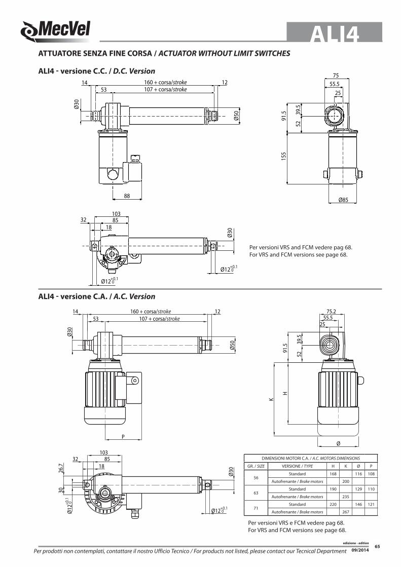
edizione - edition65
ALI4
09/2014Per prodotti non contemplati, contattare il nostro Ufficio Tecnico / For products not listed, please contact our Tecnical Department
14
Ø30
53 107 + corsa/stroke12160 + corsa/stroke
Ø12
853218
103
26.7
30
55.5
52
75.2
25
Ø50
P
Ø12
Ø
Ø30
39.5
91.5
H
K
+0.1 0
+0.1
0ALI4 - versione C.C. / D.C. Version
ALI4 - versione C.A. / A.C. Version
ATTuAToRe SeNzA FINe CoRSA / ACtuAtoR wIthout LIMIt SwItChES
DIMENSIONI MOTORI C.A. / A.C. MOTORS DIMENSIONS
GR. / SIZE VERSIONE / TYPE H K Ø P
56Standard 168 116 108
Autofrenante / Brake motors 200
63Standard 190 129 110
Autofrenante / Brake motors 235
71Standard 220 146 121
Autofrenante / Brake motors 267
160 + corsa/stroke107 + corsa/stroke
1453
88
12 55.575
25
Ø30
Ø30
10385
1832
91.5
52
155
Ø12+0.1 0
Ø12+0.1 0
Ø50
Ø85
39.5
Per versioni VRS e FCM vedere pag 68.For VRS and FCM versions see page 68.
Per versioni VRS and FCM vedere pag 68.For VRS and FCM versions see page 68.

edizione - edition66
ALI4
09/2014
Ø50
12
107 + corsa/stroke 83
Ø30
P
14 190 + corsa/stroke
133115
18
32
2690
1243
Ø30
8426
Ø12
52
7655
25
44
Ø
39.5
91.5
H
K
+0.1
0
+0.1 0
ALI4-F - versione C.C. / D.C. Version
ALI4-F - versione C.A. / A.C. Version
ATTuAToRe CoN FINe CoRSA INTeGRATo / ACtuAtoR wIth INtEGRAtED LIMIt SwItChES
DIMENSIONI MOTORI C.A. / A.C. MOTORS DIMENSIONS
GR. / SIZE VERSIONE / TYPE H K Ø P
56Standard 168 116 108
Autofrenante / Brake motors 200
63Standard 190 129 110
Autofrenante / Brake motors 235
71Standard 220 146 121
Autofrenante / Brake motors 267
Ø30
43
5239
.5
91.5
2547
90120.5
Ø85
155
12
Ø50
88
190 + corsa
107+ corsa83
14
18
32 133115
Ø12+0.1 0 83.9
Ø30
Ø12+0.1 0
Per versioni VRS e FCM vedere pag 68.For VRS and FCM versions see page 68.
Per versioni VRS e FCM vedere pag 68.For VRS and FCM versions see page 68.

edizione - edition67
ALI4
09/2014
SIGLA DI oRDINAzIoNe - oRDERING KEY
ALI4 / 0250 / M01 / CA-400/50-T-56-4-0,09 / B5+S1+AB / FC1 /M0 / 1 / e0 / 2FC0 / P0T01A / IP65 / P1 / A1 / A+B / N.DIS
MoDeLLo / MoDEL: ALI4 / ALI4-F / ALI4-FCM / ALI4-FCI ALI4-VRS / ALI4-VRS-F / ALI4-VRS-FCM ALI4-VRS-FCI CoRSA / StRoKE: mm es. 250 mm = 0250VeLoCITÀ / SPEED: mm/s ALI4 (Pag. 64) Indicare: vedi tabelle / Advise: choose among M00 = Velocità non contemplate / Not standard speed Versione PAM / Flanged Version = Rpm Indicare rapporto riduzione + passo stelo Advise reduction ratio and screw pitchMoToRe / MotoR: (Pag. 64) Indicare solo con motore: / Advise only if with motor: In C.A.: versione, tensione, tipo, grandezza, n°poli, potenza version, voltage, type, size, n°pole, power In C.C.: versione, tensione, grandezza, n°giri version, voltage, size, Rpm In versione predisposizione motore “PAM” indicare: 0 With motorflange only put 0 In versione PAM a disegno indicare: PD With special motorflange put: PDVARIANTI MoToRe CA / AC MotoR oPtIoNS: (Pag.ACCESSORI/ACCESSORIES) Flangia motore: solo in versione PAM - esempio PAM 56B14 indicare 56B14 Motorflange: for motorflange version only advise size - i.e.for IEC56 B14 put 56B14 Senza motore o con motore in C.C.: Omettere tutti i parametri sottoindicati No motor or DC motor: leave all following parameters blank Tipo Servizio: Indicare se diverso da S3 (std) Service rate: Advise if different than S3 (std) Classe isolamento: Indicare se diverso da F (std) Insulation class: Advise if different than F (std) Grado Protezione: Indicare se diverso da IP55 (std) Protection Degree: Advise if different than IP55 (std) Tipo freno: solo se autofrenante: ES. FECA Brake type: for brakemotors only: ES. FECA opzioni: Indicare se richiesto (ES. AB Albero Bisporgente) Options: Advise if needed (ES. AB 2’shaft)oRIeNTAMeNTo FINe CoRSA / LIMIt SwItChES PoSItIoN: (Pag. 69) Senza / None: Omettere / Leave blank FC1 / FC2oRIeNTAMeNTo MoToRe / MotoR PoSItIoN: (Pag. 69) Senza / None: Omettere / Leave blank M0 / M1oRIeNTAMeNTo MoRSeTTIeRA / E-BoX PoSItIoN: (Pag. 69) 1 (Standard), 2, 3, 4 Senza Motore o motore in CC / No Motor or DC motor: Omettere / Leave blankeNCoDeR / ENCoDER: (Pag. ACCESSORI/ACCESSORIES) Senza / None: Omettere / Leave blankFINe CoRSA / LIMIt SwItChES: (Pag. ACCESSORI/ACCESSORIES) Senza / None: Omettere / Leave blankPoTeNzIoMeTRo / PotENtIoMEtER: (Pag. ACCESSORI/ACCESSORIES) Senza / None: Omettere / Leave blankGRADo PRoTezIoNe / PRotECtIoN CLASS: IP55 (Std): omettere / leave blank IP65 AA Allestimento Acciaierie / Steel works Altro / other: Specificare / AdviseATTACCo PoSTeRIoRe / REAR END: (Pag. 69) P0 = Senza / None P2 = Occhio / Eyelet (90°) P1 = Occhio / Eyelet (standard) P3 = Attacco a Disegno / Special (provide drawing)ATTACCo ANTeRIoRe / FRoNt END: ALI4 (Pag. 68) A0 = Senza / None A1 = Occhio / Eyelet (Std) A2 = Forcella Fissa / Yoke A3 = Forcella + Clip / Yoke + Clip A4 = Testa a Snodo / Rod end A6 = Femmina M12 / M12 female A7 = Maschio M12 / M12 male A9 = Attacco a Disegno / Special (provide drawing)oPzIoNI / oPtIoNS: Senza / None: Omettere / Leave blank A = Versione Inox (asta, attacco anteriore) / Stainless steel version (rod, front end) B = Protezione soffietto / Bellows boot C = Vite Scoperta / Naked Screw e = Guarnizioni in viton / Viton seals L = Antirotazione / Anti-rotation device (AR0/AR1 Pag. 131) FX = Verniciatura Protettiva Steel It / Protective Painting Steel It FXC = Cataforesi / Protective treatment Cataphoresis G = Chiocciola di sicurezza / Safety nut S = Limitatore di coppia su asse motore / Torque limiter on motor flange T = Sporgenza albero opposta motore (solo ALI4 / ALI4-F) Additional shaft (opposite to motorside - ALI4 / ALI4-F only) (Pag. ACCESSORI/ACCESSORIES) z = Versione bassa rumorosità / Low noise versionVARIANTI / VERSIoNS: N° Disegno / Drawing number: Per Condizioni non Contemplate / Presence of not standard options Senza / None: Omettere / Leave blank
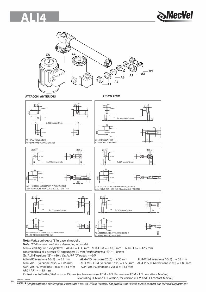
edizione - edition68
ALI4
09/2014 Per prodotti non contemplati, contattare il nostro Ufficio Tecnico / For products not listed, please contact our Tecnical Department
ATTACCHI ANTeRIoRI FRoNt ENDS
Nota: Variazioni quota “B”in base al modelloNote: “B” dimension variations depending on modelALI4 = Vedi figure / See pictures ALI4-F = + 30 mm ALI4-FCM = + 42,5 mm ALI4-FCI = + 42,5 mmcon chiocciola di sicurezza “G” aggiungere 30 mm / with safety nut “G” = + 30 mm(Es. ALI4-F opzione “G” = +30) / (i.e. ALI4-F “G” option = +30)ALI4-VRS (versione 16x5) = + 25 mm ALI4-VRS (versione 20x5) = + 55 mm ALI4-VRS-F (versione 16x5) = + 55 mmALI4-VRS-F (versione 20x5) = + 85 mm ALI4-VRS-FCM (versione 16x5) = + 53 mm ALI4-VRS-FCM (versione 20x5) = + 83 mmALI4-VRS-FCI (versione 16x5) = + 53 mm ALI4-VRS-FCI (versione 20x5) = + 83 mmAR0 / AR1 = + 15 mm Protezione Soffietto / Bellows = + 15 mm (escluso versione FCM e FCI. Per versioni FCM e FCI contattare MecVel) (excluding FCM and FCI version, for versions FCM and FCI contact MecVel)
A4A3
A2A6
A1
A7
CA CC
Ø12+0.1 0
A3 = FORCELLA CON CLIP DIN 71752 / UNI 1676A3 = FIXING YOKE WITH CLIP DIN 71752 / UNI 1676
A6 = TERMINALE CON FILETTO FEMMINA M12A6 = M12 TREADED FEMALE END
B=172+corsa/stroke
32
Ø30
14
Ø30
20
M12
B=223+corsa/stroke
B=160+corsa/stroke
Ø12+0.1 0
Ø12+0.1 0
A1 = OCCHIO (Standard)A1 = STANDARD FIXING (Standard)
14
32
Ø30
32
Ø30
Ø12 H8
24
14
12 24
Ø12+0.1 0
Ø30
B=162+corsa/stroke
A4 = TESTA A SNODO DIN 648 serie K / ISO 6126A4 = FIXING WITH ROD END DIN 648 serie K / ISO 6126
Ø12+0.1 0
A7 = TERMINALE FILETTO MASCHIO M12A7 = M12 TREADED MALE END
Ø30
32
14 34
Ø30
B=225+corsa/stroke
B=168+corsa/stroke
27
Ø12+0.1 0
Ø12 H7
Ø30
Ø12+0.1 0
A2 = FORCELLA FISSAA2 = LOCKED YOKE FIXING
Ø30
32
Ø12+0.1 0
32
14
Ø30
12
17
1612
12
14
1214
M12

edizione - edition69
ALI4
09/2014Per prodotti non contemplati, contattare il nostro Ufficio Tecnico / For products not listed, please contact our Tecnical Department
ATTACCo PoSTeRIoRe/ ReAR eND oRIENtAMENto MoRSEttIERA/ E-BoX PoSItIoN
P1 P2Ruotato di 90°Rotated through 90°
(Standard)
1 (Standard)
3
24
3
2 (Standard)
4
M0 M1
1
3
4
3
4 2
1StANDARD StANDARD
1 (Standard)
3
24
3
2 (Standard)
4
FC1(Standard)
(solo M0/only M0)
FC2(solo M1/only M1)
M1 M0(Standard)
oRIeNTAMeNTo FINeCoRSA / LIMIt SwItChES PoSItIoN
2
oRIeNTAMeNTo MoToRe / MotoR PoSItIoN

edizione - edition70
ALI4
09/2014
Esempi di collegamento motori in Vac.L’ attuatore standard non è fornito con cablaggio.L’ eventuale cablaggio è fornibile su richiesta.
Examples of connection in Vac. The ‘standard actuator is not provided with wiring. The ‘possible wiring can be supplied on request.
Motore asincrono trifase3-phase motor
Motore asincrono trifase 2 velocitàDouble speed 3-phase motor
Motore monofase avvolgimento equilibrato1-phase motor with balanced winding
1 2
4
2 14
1 2
4
2 14
1 24
2 14
2 14
INDICAzIoNI DI CoLLeGAMeNTo - CoNNECtIoN INFoRMAtIoN
Collegamento solo motore
Collegamento motore e 2 finecorsa
Collegamento motore e 3 finecorsa
Collegamento motore e 2 finecorsa cablati con diodi.
Motor only connection.
Connection for Motor and 2 limit switches.
Connection for Motor and 3 limit switches.
Connection for Motor and 2 limit switched diode-wired.
Esempi di collegamento in Vdc.L’ attuatore standard non è fornito con cablaggio.L’ eventuale cablaggio è fornibile su richiesta.
Examples of connection in Vdc. Standard actuator is not provided with wiring. Wiring can be supplied on request.

edizione - edition71
ALI4
09/2014
DIAGRAMMI DI CoRReNTe - CuRRENt DIAGRAM DIAGRAMMI DI VeLoCITÀ - SPEED DIAGRAM
Diagrammi riferiti alla tensione di alimentazione 24Vdc.Per tensione 12Vdc raddoppiare il valore di corrente e ridurre il valore di carico del 20%.
Diagrams valid for 24Vdc power supply.For 12Vdc power supply currents are doubled and loads are 20% lower.
M22M24
M21
M20
M250
20
40
60
80
100
120
0 2000 4000 6000 8000 10000 120000
2
4
6
8
10
12
14
16
0 2000 4000 6000 8000 10000 12000
M29
0
10
20
30
40
50
60
70
0 2000 4000 6000 80000
2
4
6
8
10
12
14
16
0 2000 4000 6000 8000
Carico (N) / Load (N)
Carico (N) / Load (N)
Carico (N) / Load (N)
Carico (N) / Load (N)
Vel
ocit
à (m
m/s
) / S
peed
(mm
/s)
Vel
ocit
à (m
m/s
) / S
peed
(mm
/s)
Diagramma di corrente motore 24Vdc con vite trapezia
Corr
ente
[A] -
Cur
rent
[A]
Corr
ente
[A] -
Cur
rent
[A]
M20
M21 M22 M23
M24 M25
M26
M27
M28 M29 M30
M23
M26
M27
M30M28
0
5
10
15
20
25
30
0 2000 4000 6000 80000
2
4
6
8
10
12
14
16
0 2000 4000 6000 8000Carico (N) / Load (N) Carico (N) / Load (N)
Vel
ocit
à (m
m/s
) / S
peed
(mm
/s)
Corr
ente
[A] -
Cur
rent
[A]
M38
M39 M40M41
M38
M39
M40M41
10000
24 Vdc Motor current diagram with acme screwDiagramma di velocità motore 24Vdc con vite trapezia 24 Vdc Motor speed diagram with acme screw
Diagramma di corrente motore 24Vdc con vite ricircolo di sfere VRS 16x5 24 Vdc Motor current diagram with ball screw VRS 16x5
Diagramma di velocità motore 24Vdc con vite ricircolo di sfere VRS 16x5 24 Vdc Motor speed diagram with ball screw VRS 16x5
Diagramma di corrente motore 24Vdc con vite ricircolo di sfere VRS 20x5 24 Vdc Motor current diagram with ball screw VRS 20x5
Diagramma di velocità motore 24Vdc con vite ricircolo di sfere VRS 20x5 24 Vdc Motor speed diagram with ball screw VRS 20x5

edizione - edition
09/201472
NoTe NotES