alitec rock wheel - woods equipment company · table of contents introduction ... detail. we...
TRANSCRIPT

OP
ER
AT
OR
'S M
AN
UA
L
MR
W
ROCK WHEELRW12RW18RW24
Effective Serial Numbers:63010503
(Rev
. 1/3
0/20
09)

2 Introduction Gen’l (Rev. 2/19/2008)
TO THE DEALER:
Assembly and proper installation of this product is the responsibility of the Woods® dealer. Read manual instructionsand safety rules. Make sure all items on the Dealer’s Pre-Delivery and Delivery Check Lists in the Operator’s Manualare completed before releasing equipment to the owner.
The dealer must complete the Product Registration online at the Woods Dealer Website or complete the mail-inform included with the Operator’s Manual. If using the mail-in form, the dealer is to return the prepaid postage portion toWoods, give one copy to the customer, and retain one copy. Failure to register the product does not diminishcustomer’s warranty rights.
TO THE OWNER:
Read this manual before operating your Woods equipment. The information presented will prepare you to do a better andsafer job. Keep this manual handy for ready reference. Require all operators to read this manual carefully and becomeacquainted with all adjustment and operating procedures before attempting to operate. Replacement manuals can beobtained from your dealer. To locate your nearest dealer, check the Dealer Locator at www.WoodsEquipment.com, or inthe United States and Canada call 1-800-319-6637.
The equipment you have purchased has been carefully engineered and manufactured to provide dependable andsatisfactory use. Like all mechanical products, it will require cleaning and upkeep. Lubricate the unit as specified.Observe all safety information in this manual and safety decals on the equipment.
For service, your authorized Woods dealer has trained mechanics, genuine Woods service parts, and the necessarytools and equipment to handle all your needs.
Use only genuine Woods service parts. Substitute parts will void the warranty and may not meet standards required forsafe and satisfactory operation. Record the model number and serial number of your equipment in the spacesprovided:
Model: _______________________________ Date of Purchase: _____________________
Serial Number: (see Safety Decal section for location) ____________________________________
Provide this information to your dealer to obtain correct repair parts.
Throughout this manual, the term NOTICE is used to indicate that failure to observe can cause damage to equipment.The terms CAUTION, WARNING, and DANGER are used in conjunction with the Safety-Alert Symbol (a triangle withan exclamation mark) to indicate the degree of hazard for items of personal safety.
Introduction 3MRW (Rev. 6/22/2007)
TABLE OF CONTENTSINTRODUCTION . . . . . . . . . . . . . . . . . . . . . . . . . . . . . . . . . . . . . . . . . . . . . . 2
GENERAL INFORMATION . . . . . . . . . . . . . . . . . . . . . . . . . . . . . . . . . . . . . 3
SPECIFICATION . . . . . . . . . . . . . . . . . . . . . . . . . . . . . . . . . . . . . . . . . . . . . . 4
SAFETY RULES . . . . . . . . . . . . . . . . . . . . . . . . . . . . . . . . . . . . . . . . . . . . . . 5
SAFETY DECALS . . . . . . . . . . . . . . . . . . . . . . . . . . . . . . . . . . . . . . . . . . . . . 8
SETUP. . . . . . . . . . . . . . . . . . . . . . . . . . . . . . . . . . . . . . . . . . . . . . . . . . . . . . 9
OPERATION . . . . . . . . . . . . . . . . . . . . . . . . . . . . . . . . . . . . . . . . . . . . . . . . 10
SERVICE. . . . . . . . . . . . . . . . . . . . . . . . . . . . . . . . . . . . . . . . . . . . . . . . . . . 12
PARTS INDEX. . . . . . . . . . . . . . . . . . . . . . . . . . . . . . . . . . . . . . . . . . . . . . . 14
REPLACEMENT PARTS WARRANTY . . . . . . . . . . . . . . . . . . . . . . . . . . . . 20
PRODUCT WARRANTY . . . . . . . . . . . . . . . . . . . . . . . . . . . . . . . . . . . . . . . 21
GENERAL INFORMATION
Some illustrations in this manual show theequipment with safety shields removed to providea better view. This equipment should never beoperated with any necessary safety shieldingremoved.
The purpose of this manual is to assist you in operatingand maintaining your equipment. Read it carefully. Itfurnishes information and instructions that will help youachieve years of dependable performance. Theseinstructions have been compiled from extensive field
experience and engineering data. Some informationmay be general in nature due to unknown and varyingoperating conditions. However, through experienceand these instructions, you should be able to developprocedures suitable to your particular situation.
The illustrations and data used in this manual were cur-rent at the time of printing, but due to possible inlineproduction changes, your machine may vary slightly indetail. We reserve the right to redesign and change themachines as may be necessary without notification.
Throughout this manual, references are made to rightand left directions. These are determined by standingbehind the equipment facing the direction of forwardtravel.
Si no lee Ingles, pida ayuda a alguien que si lo lea para que le
traduzca las medidas de seguridad.
LEA EL INSTRUCTIVO!!
WARNING
(Rev. 1/30/2009)
4 Introduction MRW (Rev. 6/22/2007)
SPECIFICATIONS
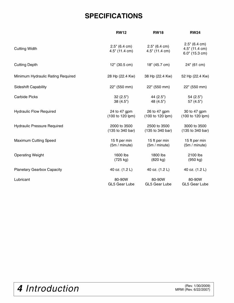
RW12 RW18 RW24
Cutting Width2.5" (6.4 cm)4.5" (11.4 cm)
2.5" (6.4 cm)4.5" (11.4 cm)
2.5" (6.4 cm)4.5" (11.4 cm)6.0" (15.3 cm)
Cutting Depth 12" (30.5 cm) 18" (45.7 cm) 24" (61 cm)
Minimum Hydraulic Rating Required 28 Hp (22.4 Kw) 38 Hp (22.4 Kw) 52 Hp (22.4 Kw)
Sideshift Capability 22" (550 mm) 22" (550 mm) 22" (550 mm)
Carbide Picks 32 (2.5")38 (4.5")
44 (2.5")48 (4.5")
54 (2.5")57 (4.5")
Hydraulic Flow Required 24 to 47 gpm(100 to 120 lpm)
26 to 47 gpm(100 to 120 lpm)
30 to 47 gpm(100 to 120 lpm)
Hydraulic Pressure Required 2000 to 3500(135 to 340 bar)
2500 to 3500(135 to 340 bar)
3000 to 3500(135 to 340 bar)
Maximum Cutting Speed 15 ft per min(5m / minute)
15 ft per min(5m / minute)
15 ft per min(5m / minute)
Operating Weight 1600 lbs(725 kg)
1800 lbs(820 kg)
2100 lbs(950 kg)
Planetary Gearbox Capacity 40 oz. (1.2 L) 40 oz. (1.2 L) 40 oz. (1.2 L)
Lubricant 80-90W GL5 Gear Lube
80-90W GL5 Gear Lube
80-90W GL5 Gear Lube
(Rev. 1/30/2009)

Safety 5Alitec Rock Wheel (04/01/2006)
INSTALLATIONHydraulics must be connected as instructed in
this manual. Do not substitute parts, modify, orconnect in any other way.
After connecting hoses, check that all controllever positions function as instructed in the Opera-tor's Manual. Do not put into service until controllever and equipment movements are correct.
OPERATION
Safety instructions are important! Read allattachment and power unit manuals; follow allsafety rules and safety decal information. (Replace-ment manuals and safety decals are available fromyour dealer. To locate your nearest dealer, checkthe Dealer Locator at www.WoodsEquipment.com,or in the United States and Canada call 1-800-319-6637.) Failure to follow instructions or safety rulescan result in serious injury or death.
If you do not understand any part of this manualand need assistance, see your dealer.
Know your controls and how to stop engine andattachment quickly in an emergency.
Operators must be instructed in and be capableof the safe operation of the equipment, its attach-ments, and all controls. Do not allow anyone tooperate this equipment without proper instruc-tions.
Keep hands and body away from pressurizedlines. Use paper or cardboard, not hands or otherbody parts to check for leaks. Wear safety goggles.Hydraulic fluid under pressure can easily penetrateskin and will cause serious injury or death.
Make sure that all operating and service person-nel know that if hydraulic fluid penetrates skin, it
must be surgically removed as soon as possible bya doctor familiar with this form of injury or gan-grene, serious injury, or death will result. CON-TACT A PHYSICIAN IMMEDIATELY IF FLUIDENTERS SKIN OR EYES. DO NOT DELAY.
Never allow children or untrained persons tooperate equipment.
PREPARATIONCheck that all hardware is properly installed.
Always tighten to torque chart specificationsunless instructed otherwise in this manual.
Counterweight ballast may be required formachine stability. Check your power unit manual orcontact your dealer.
Air in hydraulic systems can cause erratic oper-ation and allows loads or equipment componentsto drop unexpectedly. When connecting equipmentor hoses or performing any hydraulic maintenance,purge any air in hydraulic system by operating allhydraulic functions several times. Do this beforeputt ing into service or al lowing anyone toapproach the equipment.
After connecting hoses, check that all controllever positions function as instructed in the Opera-tor's Manual. Do not put into service until controllever and equipment movements are correct.
Protective hose sleeves must cover all hydrau-lic hoses within 20 inches of the operator and besecured onto metal hose fittings. Replace hoses orsleeves if damaged or if protective sleeve cannotbe properly positioned or secured.
Make sure all hydraulic hoses, fittings, andvalves are in good condition and not leaking beforestarting power unit or using equipment. Check androute hoses carefully to prevent damage. Hosesmust not be twisted, bent sharply, kinked, frayed,pinched, or come into contact with any movingparts. Operate moveable components through fulloperational range to check clearances. Replaceany damaged hoses immediately.
Always wear relatively tight and belted clothingto avoid entanglement in moving parts. Wearsturdy, rough-soled work shoes and protectiveequipment for eyes, hair, hands, hearing, and head.
Be sure attachment is properly secured,adjusted, and in good operating condition. Couplerlockpins must be fully extended and properlyengaged into attachment retaining slots.
(Safety Rules continued on next page)
Safety is a primary concern in the design andmanufacture of our products. Unfortunately, ourefforts to provide safe equipment can be wipedout by an operator’s single careless act.
In addition to the design and configuration ofequipment, hazard control and accident preven-tion are dependent upon the awareness, con-cern, judgement, and proper training ofpersonnel involved in the operation, transport,maintenance, and storage of equipment.
It has been said, “The best safety device is aninformed, careful operator.” We ask you to bethat kind of operator.
SAFETY RULESATTENTION! BECOME ALERT! YOUR SAFETY IS INVOLVED!

6 Safety Alitec Rock Wheel (04/01/2006)
(Safety Rules continued from previous page)
Power unit must be equipped with ROPS andseat belt/operator restraint. Keep seat belt/operatorrestraint securely fastened/engaged. Falling offpower unit can result in death from being run overor crushed. Keep ROPS systems in place at alltimes.
Make sure all safety decals are installed.Replace if damaged. (See Safety Decals section forlocation.)
Make sure shields and guards are properlyinstalled and in good condition. Replace if dam-aged.
Inspect and clear area of stones, branches, orother hard objects that might be thrown, causinginjury or damage.
OPERATION
Improper operation can cause the machine totip or roll over and cause injury or death.
• Keep power unit lift arms and attachment aslow as possible.• Do not travel or turn with power unit lift armsand attachment raised.• Turn only on level ground.• Go up and down slopes, not across them.• Keep the heavy end of the machine uphill.• Do not overload the machine.
Never use attachment to carry loads that exceedthe rated operating capacity or other specificationsof the power unit. Check your power unit manual orsee your dealer for rated operating capacity.Exceeding this capacity can cause machine to tip,roll over, or present other hazards that can causeinjury or death.
Do not allow bystanders in the area when oper-ating, attaching, removing, assembling, or servic-ing equipment.
Consult local utilities before digging. Knowlocation and depth of all underground cables, pipe-lines, and other hazards in working area and avoidcontact.
Contact with high voltage, overhead powerlines, underground cables, gas lines, and otherhazards can cause serious injury or death fromelectrocution, explosion, or fire.
Keep bystanders away from equipment.
Do not operate or transport equipment whileunder the influence of alcohol or drugs.
Operate only in daylight or good artificial light.
Keep hands, feet, hair, and clothing away fromequipment while engine is running. Stay clear of allmoving parts.
Always comply with all state and local lightingand marking requirements.
Do not allow riders. Do not lift or carry anybodyon the power unit or attachments.
Always sit in power unit seat when operatingcontrols or starting engine. Securely fasten seatbelt/operator restraint, place transmission in parkor neutral, engage brake and ensure all other con-trols are disengaged before starting power unitengine.
Look down and to the rear and make sure areais clear before operating in reverse.
Use extreme care when working close to fences,ditches, other obstructions, or on hillsides.
Do not operate on steep slopes.
Do not stop, start, or change directions sud-denly on slopes.
Use extreme care and reduce ground speed onslopes and rough terrain.
Watch for hidden hazards on the terrain duringoperation.
Stop power unit and implement immediatelyupon striking an obstruction. Dismount power unit,using proper procedure. Inspect and repair anydamage before resuming operation.
NEVER GO UNDERNEATH EQUIPMENT. Neverplace any part of the body underneath equipmentor between moveable parts even when the enginehas been turned off. Hydraulic system leak-down,hydraulic system failures, mechanical failures, ormovement of control levers can cause equipmentto drop or rotate unexpectedly and cause severeinjury or death.
• Service work does not require going under-neath.• Read Operator's Manual for service instruc-tions or have service performed by a qualifieddealer.
Leak down or failure of mechanical or hydraulicsystem can cause equipment to drop.
Before making any adjustments on attachment,stop engine and engage parking brake. Neveradjust or work on attachment while the power unitor attachment is running.
SAFETY RULESATTENTION! BECOME ALERT! YOUR SAFETY IS INVOLVED!

Safety 7Alitec Rock Wheel (04/01/2006)
Before leaving operator's seat, lower lift armsand put attachment on the ground. Engage brake,stop engine, remove key, and remove seat belt.
MAINTENANCE
Before leaving operator's seat, lower lift armsand put attachment on the ground. Engage brake,stop engine, remove key, and remove seat belt.
NEVER GO UNDERNEATH EQUIPMENT. Neverplace any part of the body underneath equipmentor between moveable parts even when the enginehas been turned off. Hydraulic system leak-down,hydraulic system failures, mechanical failures, ormovement of control levers can cause equipmentto drop or rotate unexpectedly and cause severeinjury or death.
• Service work does not require going under-neath.• Read Operator's Manual for service instruc-tions or have service performed by a qualifieddealer.
Do not modify or alter or permit anyone else tomodify or alter the equipment or any of its compo-nents in any way.
Your dealer can supply original equipmenthydraulic accessories and repair parts. Substituteparts may not meet original equipment specifica-tions and may be dangerous.
When removing front wheel pins, be sure tosupport the front of the depth skid to preventhands or feet from being crushed.
Always wear relatively tight and belted clothingto avoid entanglement in moving parts. Wearsturdy, rough-soled work shoes and protectiveequipment for eyes, hair, hands, hearing, and head.
Do not allow bystanders in the area when oper-ating, attaching, removing, assembling, or servic-ing equipment.
Be sure attachment is properly secured,adjusted, and in good operating condition. Couplerlockpins must be fully extended and properlyengaged into attachment retaining slots.
Never perform service or maintenance withengine running.
Keep all persons away from operator controlarea while performing adjustments, service, ormaintenance.
Tighten all bolts, nuts and screws to torquechart specifications. Check that all cotter pins areinstalled securely to ensure equipment is in a safecondition before putting unit into service.
Make sure all safety decals are installed.Replace if damaged. (See Safety Decals section forlocation.)
Make sure shields and guards are properlyinstalled and in good condition. Replace if dam-aged.
Do not disconnect hydraulic lines until all sys-tem pressure is relieved. Lower unit to ground,stop engine, and operate all hydraulic controllevers.
Leak down or failure of mechanical or hydraulicsystem can cause equipment to drop.
STORAGE
Follow manual instructions for storage.
Keep children and bystanders away from stor-age area.
SAFETY RULESATTENTION! BECOME ALERT! YOUR SAFETY IS INVOLVED!

8 Safety MRW (Rev. 6/22/2007)
BE CAREFUL!
Use a clean, damp cloth to clean safety decals.
Avoid spraying too close to decals when using a pressure washer; high-pressure water can enter through very small scratches or under edges of decals causing them to peel or come off.
Replacement safety decals can be ordered free from your Woods dealer. To locate your nearest dealer, check the Dealer Locator at www.WoodsEquipment.com, or in the United States and Canada call 1-800-319-6637.
MODEL NO. SERIAL NO.
Woods Equipment CompanyOregon, Illinois, U.S.A.
Serial Number Plate
AVOID INJURY
OR DEATH
Bystanders must stay 6M (20 ft.) away.
Stop engine before servicing or cleaning
this equipment.
DANGER
D0062-A
WARNING
PINCH AREAKeep clear during operation.
D0192
WARNINGFLYING OBJECT
HAZARDKeep clear during
operation.D0195
WARNINGFLYING OBJECT
HAZARDKeep clear during
operation.
D0209
TO AVOID SERIOUS INJURY OR DEATH: � Read attachment and power unit manuals before you use,
service, or repair machine. Follow all safety rules and instructions. (Manuals can be obtained from your dealer, or in the United States and Canada call 1-800-319-6637.)
� Use only when sitting in operator's seat with seat belt/ operator restraint fastened.
� Before leaving operator's seat, follow power unit manual instructions, lower lift arms and attachment to ground, stop engine, remove key, engage brake, and remove seat belt/ operator restraint.
� Never let children or untrained persons run equipment.
WARNING
D0404-C
������������ ���� �� �� ���� ��� ��������� ������� ���� �� ������ ����� �������� �� ������
� Check for leaks with cardboard; never use hand.� Before loosening fittings: lower load, release pressure, and
be sure oil is cool.� Consult physician immediately if skin penetration occurs.
WARNING
19924-B
WARNING
54519-B
FALLING OFF CAN RESULT IN BEING RUN OVER.■ Skid steer must have ROPS and seat belt/operator restraint.
Keep seat belt/operator restraint securely fastened.
■ Never allow riders.
RAISED EQUIPMENT CAN DROP AND CRUSH.■ Never go under raised equipment or raised skid steer lift
arms. They can drop from hydraulic or mechanical failure, or moving control levers.
■ Service work does not require going under equipment. Read manual instructions.
FALLING OFF OR GOING UNDER MACHINE CAN RESULT IN SERIOUS INJURY OR DEATH.
D0062
D0192
D0195
D0209
54519
D0404
19924
See page 14 for locations.
SAFETY & INSTRUCTIONAL DECALSATTENTION! BECOME ALERT! YOUR SAFETY IS INVOLVED!
Replace Immediately If Damaged!
Setup 9MRW (Rev. 6/22/2007)
SETUPAlthough the Woods attachment is supplied fullyassembled, some simple checks should be performedbefore operation begins.
SAFETY DECALSThe safety decals existing on the attachment should beclearly readable and always followed. The location anddescription of the decals is shown in the exploded dia-gram on page 14. Copies of the decals are shown in“Safety Decals” section.
LUBRICATIONAll attachment joint grease fittings should be greaseduntil grease flows out of the joint.
NOTICE■ Type of lubrication should be 80-90W gear lube,with an EP (extreme pressure) rating of GL-5 mini-mum.
HOSES / FITTINGSHydraulic fittings are used to connect all attachmenthoses. All fittings should be tight and free of hydraulicleaks. Hoses must be free of crimps or cuts that mightresult in leakage. Check your attachment before opera-tion to make sure all hose routings are kink-free andallow for maximum movement of all extended, lift/lower,and/or swing motion required during normal operation.
WIRE HARNESSThe wiring harness to the electro hydraulic valve blockshould be routed to prevent catching or pinching whensideshifting or lowering the wheel fully into the ground.Ensure the wiring harness is routed under the sideshiftframe top angle into the loader cab to prevent trippingwhen entering or exiting the loader.
WHEEL ASSEMBLYFor proper operation, wheel picks must be installed inevery holder on the wheel.

10 Operation MRW (Rev. 6/22/2007)
OPERATIONA careful operator is the best protection against acci-dents. Most accidents involving operators of industrialequipment are caused by failure to observe basicsafety precautions. Familiarize yourself with the safetyprecautions listed below.
SAFETY PRECAUTIONSAccidents are preventable with your help.
■ Before operating this equipment, the followingsafety information should be read and understood.In addition, each individual working with the equip-ment should be familiar with the safety precau-tions.
Exercise extreme caution when hitching and removingthe attachment, operating with other workers present,and servicing the unit.
Woods always makes the operator’s safety a prioritywhen designing machinery. Exposed moving parts areguarded whenever possible for safety. However, not allmoving parts can be shielded in order to ensure properoperation. The operator’s manual and the safety decalson the machine, provide important safety informationand should be observed closely. If safety decalsbecome difficult to read, replace them immediately (see“Safety Decals”).
MANDATORY SAFETY SHUTDOWN PROCEDUREBefore cleaning, adjusting, lubricating, or servicing thisunit, always follow the mandatory safety shutdown pro-cedure:
1. Move the skid steer loader propulsion control leverto the “neutral” position.
2. Shut off the attachment by shutting off the auxiliaryhydraulic output.
3. Lower the loader lift arms completely and roll theattachment forward so it is securely resting on firmground or the shop floor.
4. Engage the loader parking brake.
5. Move the loader throttle to the slow idle position,shut the engine off, and remove the ignition key.
6. Keep the key with you at all times when working onthe unit so no one can start the engine without yourknowledge.
■ Failure to follow the procedures before clean-ing, adjusting, lubricating, or servicing this unitcould lead to serious injury or death.
OPERATION
■ The following precautions must be observedfor the safety of the operator and/or service per-sonnel.
■ Never crawl under raised loader arms.
■ Never use your hands as escaping fluid underpressure can penetrate the skin causing seriousinjury. If hydraulic fluid does penetrate the skin,seek immediate medical attention by a doctorfamiliar with this type of injury or gangrene mayresult.
■ Never allow hands or feet near any workingpart of the attachment unless the mandatory safetyshutdown procedure has been completed.
1. Read and observe all safety information anddecals on the skid steer loader and attachmentbefore operating the unit. (See Safety Decals). Inaddition, familiarize yourself with all loader safetydevices and check daily that they are functioningproperly.
2. Refer to the safety section of your skid loaderoperator’s manual and observe all safetyrecommendations set forth in that manual.
3. When loading, keep attachment as low to rampsand trailer as possible.
4. Always lower the loader arms fully before leavingthe skid steer seat.
5. Be sure to raise the attachment totally off theground before sideshifting.
6. Carefully inspect all hydraulic hoses andconnections on a routine basis. Always use a pieceof cardboard when searching for leaks.
7. Be sure to exercise the mandatory safetyshutdown procedure, before proceeding with anywork on the attachment.
The rock wheel is a hydraulically powered attachmentintended for cutting asphalt or concrete surfaces. Theperformance of the attachment can vary greatlydepending upon how it is used and operated. There-
A���WARNING
A���WARNING
A���WARNING

Operation 11MRW (Rev. 6/22/2007)
fore, the recommended operating procedures con-tained within this manual should be followed at all timesfor maximum productivity.
Prior to operating the attachment, read this entire man-ual. Follow all safety guidelines in this manual andsafety decals on the unit. Make sure that all guards,shields, and decals are in place and in good conditionprior to operation.
As noted in the Specifications Section, the attachmentrequires a minimum hydraulic supply of 25 gallons perminute. (100 liters per minute) at 2000 psi (135 bar).
NOTICE■ Insufficient hydraulic power will result in poorperformance. Check auxiliary high flow per factoryspecifications.
ATTACHING TO LOADERTo attach the unit to the loader, start the loader engineand rotate the couplers out. Pull both coupler levers upto the vertical position. Move the machine forward andpick up the attachment. Rotate the attachment backand push both coupler levers completely down. Makesure the two wedges are completely down andengaged. See operating instructions in the loader man-ual.
In attaching the unit to the skid steer, ensure that allhydraulic hoses are coupled securely to the quick cou-plers. Five hoses are to be connected; motor pressure,motor return, motor case drain, and two high flowhydraulic hoses.
NOTICE■ All hoses should be free of kinks, cuts, or abra-sions for safe operation.
TO OPERATE1. Engage the hydraulic power, set the depth arm to
the proper depth setting and lower the rock wheelslowly.
2. Actuate the bucket cylinder function for rollout untilthe wheel depth pad comes in contact with thepavement surface.
3. Before advancing the host vehicle, allow the wheelto operate until it reaches the desired depth.
NOTICE■ For most effective operation, the majority of theweight of the unit should be placed on the rockwheel with the loader arms fully lowered.
■ Operating the rock wheel with the loader armsin the float position will result in excessive vibra-tion and should be avoided.
4. With front depth control arm and pad set foracceptable cutting depth, the loader functionshould be used for lifting or lowering during rockwheel operation.
5. Excessive ground speed will stall wheel rotation.The hydraulic relief valve on the skid steer willprevent damage from occurring by diverting all flowfrom the wheel motor and the rotation of the rockwheel will stop. When this occurs, simply stop orslightly reverse the forward drive of the hostvehicle. For maximum productivity, the rock wheelshould always be operated at full engine throttle toensure that full hydraulic horsepower is available tothe cutting wheel.
NOTICE■ The bucket cylinder function should never beused to lift the wheel when it is stalled due to theexistence of secondary reliefs on some host vehi-cle bucket cylinders.
SIDESHIFT OPERATIONThe two auxiliary hoses when connected to the auxil-iary hydraulics of the skid steer, provide hydraulicpower necessary for depth and sideshift operations. Tooperate the sideshift control, set the options switch to“sideshift” and actuate auxiliary control. The rock wheelwill freely shift on the sideshift rods. In the event thatthe direction of travel does not correspond with the sideof the auxiliary control, simply switch the sideshifthoses.
HYDRAULIC DEPTH CONTROLTo operate the hydraulic depth control, set the optionsswitch to “depth” and actuate the auxiliary hydraulics toachieve the desired depth.
12 Service MRW (Rev. 6/22/2007)
SERVICEProper service of the attachment will result in longer lifeand the more productive and cost effective operation.There are two basic categories of service required,pick/holder replacement and component lubrication.For proper operation, the picks should be checked andlubricated daily to ensure that they can freely rotate intheir holders.
■ Before performing any maintenance on theunit, perform the mandatory safety shutdown pro-cedure.
PICK / HOLDER REPLACEMENTAs regular use takes place, normal wear of the carbidepicks will occur with the outer most picks wearing first.The pick tool included with the rock wheel should beused to remove the picks from the cast holders. In theevent the pick tool is not available, any hardenedpunch or tool allowing access to the bottom of the hold-ers can be used.
NOTICE■ Welder must be grounded directly to drum dur-ing pick holder replacement or severe bearingdamage will result.
■ Never drive the pick in by striking directly onthe end of the pick as this can cause the pick tochip and cause injury or create small stress frac-tures in the pick resulting in premature wear.
A length of pipe with a 3/4 - 1 inch inside diameter canbe placed over the pick to protect it from a direct hit.Striking a small piece of wood placed on the pick toabsorb the shock will prevent damage.
■ Always wear safety glasses when performingthis operation. Hardened tools and picks can shat-ter causing injury.
The factory installed carbide pick chosen for use is ageneral purpose pick as the rock wheel is basicallyused for concrete and asphalt cutting applications.Specify B1050S.
To prevent the picks from seizing in the holders, thepicks should be sprayed with diesel fuel at the end ofeach day. This will break down the asphalt build up inthe holders and prevent premature wear by allowingthe picks to rotate in the holders.
If the pick remains in the holder beyond its intendedreplacement point, it reduces the cutting performanceand will not protect the holder. Inspect the cuttingwheel every half hour of operation. Check the picksand holders for wear. If the picks are worn enough toindicate slight holder wear, replace the picks.
WHEEL HARDFACINGAs the wheel is used, it will be necessary to hardfacethe wear points on the wheel and holders. This processis required on a repetitive basis. The warranty policywill not cover damage to the wheel or holders due tonegligence.
LUBRICATIONLubricate the grease points daily on all wheels as wellas both sideshift rods and the depth arm.
The lubricant in the gear case of the planetary must bechanged within the first 50 hours of operation. Thereaf-ter, the lubricant need only be changed once per yearor every 1000 hours whichever occurs first.
NOTICE■ Type of lubricant should be EP90W gear lube,with an EP (extreme pressure) rating of GL-5 mini-mum.
The lubricant can be changed by removing the drainplug located on the bottom of the planetary gear box.Allow lubricant to drain. Remove level plug, 90° fromdrain plug. Refill until oil is at level plug (approximately40 oz.).
BOLT TORQUERe-torque all wheel bolts after five (5) hours of opera-tion to 175 ±5 lbs-ft.
■ Before servicing this unit, the mandatory safetyshutdown procedure must be completed. See“Safety Precautions”.
■ Exercise extreme caution during this operationto prevent tipping of the unit.
A���WARNING
A���WARNING
A���WARNINGA���WARNING

Service 13MRW (Rev. 6/22/2007)
WHEEL REMOVAL1. Attach the rock wheel to the skid loader and move
it to a hard, flat surface. Lower the loader arms untilthe attach frame wheels are firmly in contact withthe ground.
2. Extend the depth foot completely.
3. Shut the skid steer engine off and remove the key.
■ Chassis should be used to prevent the wheelfrom tipping in steps 4.
4. 2.5" Wheel Only - Remove the six bolts attachingthe wheel to the drive hub.
4. 4.5" Wheel Only - Loosen the nine bolts mountingthe planetary gearbox to the frame. Remove the sixbolts attaching the wheel to the drive hub.
5. Remove the nine planatory mounting bolts andslide the gearbox out and down in pilot hole toprovide clearance for wheel removal.
6. Enter the loader and sideshift the planetary/cuttingwheel assembly to the left to separate the cuttingwheel from the planetary gearbox.
7. Slowly and carefully raise the loader arms toelevate the chassis just high enough to provideclearance to roll the wheel out.
■ Chassis should be raised only high enough toallow the wheel to roll under the front of the chas-sis.
■ If the cutting wheel becomes lodged betweenthe cutting wheel chassis and the end of the plane-tary gearbox, do not attempt to dislodge the wheelwhile in the raised position. Never place hands orany part of your body in, around or under thewheel. The wheel may fall causing serious injury.
8. Shut off skid steer and remove key.
9. While carefully supporting the wheel, roll it fromunder the chassis for service.
■ Use extreme caution during this operation toprevent planetary from tipping and falling.
PLANETARY REMOVAL1. Remove the wheel from the attachment as
previously described.
2. Remove the motor by removing the two motormounting bolts.
3. Fully support the planetary with hoist and removethe nine planetary flange mounting nuts.
4. Carefully slide the planetary from the rock wheelchassis with a hoist or similar device rated for morethan 250 lbs. capacity.
SIDESHIFT CYLINDER REMOVAL1. With the attachment on a level surface, remove
both one-inch retaining rings from cylindermounting pins.
2. Disconnect both hydraulic hoses.
3. Remove both cylinder mounting pins.
A���WARNING
A���WARNING
A���WARNING
A���WARNING
14 Parts MRW (Rev. 6/22/2007)
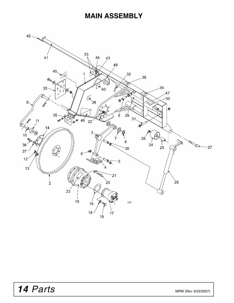
MAIN ASSEMBLY

Parts 15MRW (Rev. 6/22/2007)
MAIN ASSEMBLY
REF PART DESCRIPTION
1 105626 Chassis RW121 105628 Chassis RW181 105630 Chassis RW242 ----- Cutting wheel, 2.5" RW12 (includes
picks)2 ----- Cutting wheel, 4.5" RW12 (includes
picks)2 ----- Cutting wheel, 2.5" RW18 (includes
picks)2 ----- Cutting wheel, 3.5" RW18 (includes
picks)2 ----- Cutting wheel, 4.5" RW18 (includes
picks)2 ----- Cutting wheel, 2.5" RW24 (includes
picks)2 ----- Cutting wheel 4.5" RW24
(includes picks)3 6019 Depth control arm RW123 6546 Depth control arm RW183 100775 Depth control arm RW244 100219 Foot pad5 T1033 Foot pad, sideshift cyl. pin6 M0003 1" Snap ring7 BB090 Spacer / washer8 M0042 Snap ring9 6531 Guide arm
10 T1006 Guide wheel bushing11 T1005 Guide wheel12 1024801 Carbide tooth, RW12 2.5" (32)
Carbide tooth, RW12 4.5" (38)Carbide tooth, RW18 2.5" (44)Carbide tooth, RW18 4.5" (44)Carbide tooth, RW24 2.5" (54)Carbide tooth, RW24 4.5" (57)
12 B1050C Carbide tooth, concrete12 B1050X Carbide tooth, concrete
w/studded retainer13 P0313 Pick holder14 101086 Disc spacer15 1011278 Planetary, Auburn 6 33.8:1 (S/N 6324 &
above RW12/18) (S/N 30039 & above RW24)
15 HC159 Gearbox, Fairfield (S/N 6323 & prior RW12/18)(S/N 30038 & prior RW24)
15 S0100033 Gearbox, Fairfield boot seal (S/N 6323 & prior RW12/18) (S/N 30038 & prior RW24)
15 S0100009 Gearbox, Fairfield oil seal (S/N 6323 & prior RW12/18) (S/N 30038 & prior RW24)
REF PART DESCRIPTION
15 HC054 Auburn shaft seal (S/N 6324 & above RW12/18) (S/N 30039 & above RW24)
15 HC054 Auburn shaft seal (S/N 6324 & above RW12/18) (S/N 30039 & above RW24)
15 S01000875 Auburn seal & brg kit (S/N 6324 & above RW12/18) (S/N 30039 & above RW24)
16 M0009 Motor gasket17 HC551 Motor, M44-13 Tooth Sauer-Danfoss
(S/N 6324 and above RW12/18) (S/N 30039 and above RW24)
17 HC550 Motor, M44-15 Tooth Sauer-Danfoss (Used on earlier models) (S/N 6323 and prior RW12/18 (S/N 30038 and prior RW24)
17 S0100013 Shaft seal18 57816 Motor mounting washer19 21666 Motor mounting bolt20 B0901 Planetary mounting bolt21 B0920 Planetary mounting washer22 B0915 Planetary mounting nut23 D0042 Planetary lube decal24 100604 Wheel25 101218 Wheel bushing26 34279 Nut, wheel27 B1609 Bolt, wheel28 C1401A1 Depth cylinder RW1228 C2201A1 Depth cylinder RW18/2429 C2201 Side shift cylinder30 T1028-1 Depth arm pin31 T1035-1 Cylinder mounting pin32 D0051 Decal, depth RW12/1832 D0105 Decal, depth RW2433 D0192 Decal, pinch point34 D0404 Decal, read manual35 M0039 Flap36 B1004 Bolt, wheel mounting37 B1021 Washer, wheel mounting38 D0011 Decal RW1238 D0010 Decal RW1838 D0245 Decal RW2439 D0323 Decal, case drain40 D0158 Decal, lift point41 105303 Slider bar42 58428 Bolt, 3/8" x 1-3/4 - 16 GR8 plt43 B0618 Nut, 3/8" - 16 GR8 Stover lock44 21757 Washer, 3/8" flat SAE plt45 D0099 Decal, pick maintenance46 D0062 Decal, bystanders stay away47 19924 Decal, high pressure48 54519 Decal, skid steer crush49 M0007 Pick tool50 D0209 Decal, no step
(Rev. 1/30/2009)

16 Parts MRW (Rev. 6/22/2007)
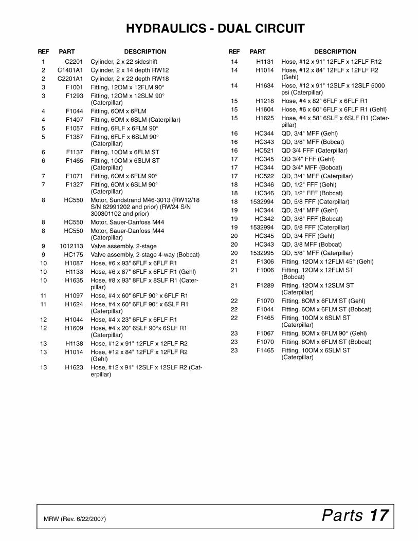
HYDRAULICS - DUAL CIRCUIT
Parts 17MRW (Rev. 6/22/2007)
HYDRAULICS - DUAL CIRCUIT
REF PART DESCRIPTION
1 C2201 Cylinder, 2 x 22 sideshift2 C1401A1 Cylinder, 2 x 14 depth RW122 C2201A1 Cylinder, 2 x 22 depth RW183 F1001 Fitting, 12OM x 12FLM 90°3 F1293 Fitting, 12OM x 12SLM 90°
(Caterpillar)4 F1044 Fitting, 6OM x 6FLM4 F1407 Fitting, 6OM x 6SLM (Caterpillar)5 F1057 Fitting, 6FLF x 6FLM 90°5 F1387 Fitting, 6FLF x 6SLM 90°
(Caterpillar)6 F1137 Fitting, 10OM x 6FLM ST6 F1465 Fitting, 10OM x 6SLM ST
(Caterpillar)7 F1071 Fitting, 6OM x 6FLM 90°7 F1327 Fitting, 6OM x 6SLM 90°
(Caterpillar)8 HC550 Motor, Sundstrand M46-3013 (RW12/18
S/N 62991202 and prior) (RW24 S/N 300301102 and prior)
8 HC550 Motor, Sauer-Danfoss M448 HC550 Motor, Sauer-Danfoss M44
(Caterpillar)9 1012113 Valve assembly, 2-stage9 HC175 Valve assembly, 2-stage 4-way (Bobcat)
10 H1087 Hose, #6 x 93" 6FLF x 6FLF R110 H1133 Hose, #6 x 87" 6FLF x 6FLF R1 (Gehl)10 H1635 Hose, #8 x 93" 8FLF x 8SLF R1 (Cater-
pillar)11 H1097 Hose, #4 x 60" 6FLF 90° x 6FLF R111 H1624 Hose, #4 x 60" 6FLF 90° x 6SLF R1
(Caterpillar)12 H1044 Hose, #4 x 23" 6FLF x 6FLF R112 H1609 Hose, #4 x 20" 6SLF 90°x 6SLF R1
(Caterpillar)13 H1138 Hose, #12 x 91" 12FLF x 12FLF R213 H1014 Hose, #12 x 84" 12FLF x 12FLF R2
(Gehl)13 H1623 Hose, #12 x 91" 12SLF x 12SLF R2 (Cat-
erpillar)
REF PART DESCRIPTION
14 H1131 Hose, #12 x 91" 12FLF x 12FLF R1214 H1014 Hose, #12 x 84" 12FLF x 12FLF R2
(Gehl)14 H1634 Hose, #12 x 91" 12SLF x 12SLF 5000
psi (Caterpillar)15 H1218 Hose, #4 x 82" 6FLF x 6FLF R115 H1604 Hose, #6 x 60" 6FLF x 6FLF R1 (Gehl)15 H1625 Hose, #4 x 58" 6SLF x 6SLF R1 (Cater-
pillar)16 HC344 QD, 3/4" MFF (Gehl)16 HC343 QD, 3/8" MFF (Bobcat)16 HC521 QD 3/4 FFF (Caterpillar)17 HC345 QD 3/4" FFF (Gehl)17 HC344 QD 3/4" MFF (Bobcat)17 HC522 QD, 3/4" MFF (Caterpillar)18 HC346 QD, 1/2" FFF (Gehl)18 HC346 QD, 1/2" FFF (Bobcat)18 1532994 QD, 5/8 FFF (Caterpillar)19 HC344 QD, 3/4" MFF (Gehl)19 HC342 QD, 3/8" FFF (Bobcat)19 1532994 QD, 5/8 FFF (Caterpillar)20 HC345 QD, 3/4 FFF (Gehl)20 HC343 QD, 3/8 MFF (Bobcat)20 1532995 QD, 5/8" MFF (Caterpillar)21 F1306 Fitting, 12OM x 12FLM 45° (Gehl)21 F1006 Fitting, 12OM x 12FLM ST
(Bobcat)21 F1289 Fitting, 12OM x 12SLM ST
(Caterpillar)22 F1070 Fitting, 8OM x 6FLM ST (Gehl)22 F1044 Fitting, 6OM x 6FLM ST (Bobcat)22 F1465 Fitting, 10OM x 6SLM ST
(Caterpillar)23 F1067 Fitting, 8OM x 6FLM 90° (Gehl)23 F1070 Fitting, 8OM x 6FLM ST (Bobcat)23 F1465 Fitting, 10OM x 6SLM ST
(Caterpillar)
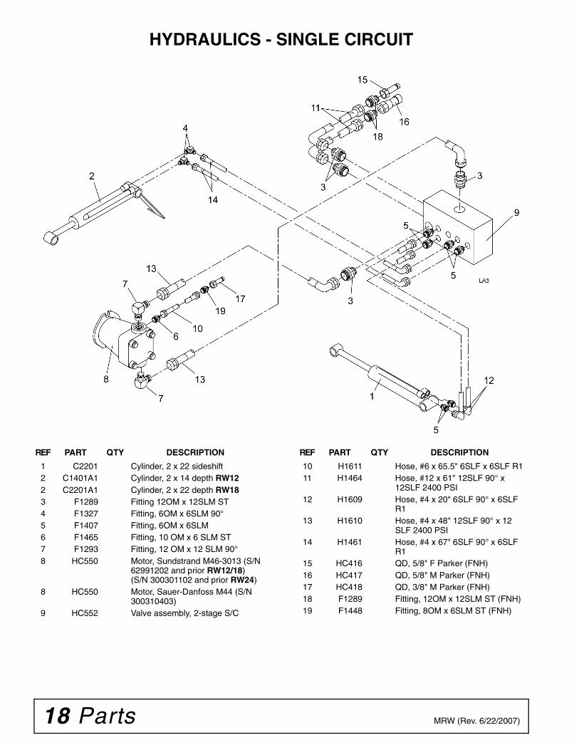
18 Parts MRW (Rev. 6/22/2007)
HYDRAULICS - SINGLE CIRCUIT
REF PART QTY DESCRIPTION
1 C2201 Cylinder, 2 x 22 sideshift2 C1401A1 Cylinder, 2 x 14 depth RW122 C2201A1 Cylinder, 2 x 22 depth RW183 F1289 Fitting 12OM x 12SLM ST4 F1327 Fitting, 6OM x 6SLM 90°5 F1407 Fitting, 6OM x 6SLM6 F1465 Fitting, 10 OM x 6 SLM ST7 F1293 Fitting, 12 OM x 12 SLM 90°8 HC550 Motor, Sundstrand M46-3013 (S/N
62991202 and prior RW12/18) (S/N 300301102 and prior RW24)
8 HC550 Motor, Sauer-Danfoss M44 (S/N 300310403)
9 HC552 Valve assembly, 2-stage S/C
REF PART QTY DESCRIPTION
10 H1611 Hose, #6 x 65.5" 6SLF x 6SLF R111 H1464 Hose, #12 x 61" 12SLF 90° x
12SLF 2400 PSI12 H1609 Hose, #4 x 20" 6SLF 90° x 6SLF
R113 H1610 Hose, #4 x 48" 12SLF 90° x 12
SLF 2400 PSI14 H1461 Hose, #4 x 67" 6SLF 90° x 6SLF
R115 HC416 QD, 5/8" F Parker (FNH)16 HC417 QD, 5/8" M Parker (FNH)17 HC418 QD, 3/8" M Parker (FNH)18 F1289 Fitting, 12OM x 12SLM ST (FNH)19 F1448 Fitting, 8OM x 6SLM ST (FNH)
Parts 19MRW (Rev. 6/22/2007)
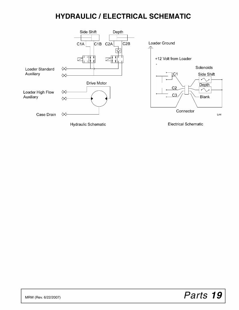
HYDRAULIC / ELECTRICAL SCHEMATIC

20 Appendix Bolt Torque & Size Charts (Rev. 3/28/2007)
BOLT TORQUE CHARTAlways tighten hardware to these values unless a different torque value or tightening procedure is listed for a specific application.Fasteners must always be replaced with the same grade as specified in the manual parts list.Always use the proper tool for tightening hardware: SAE for SAE hardware and Metric for metric hardware.Make sure fastener threads are clean and you start thread engagement properly. All torque values are given to specifications used on hardware defined by SAE J1701 MAR 99 & J1701M JUL 96.
Diameter (Inches)
WrenchSize
MARKING ON HEAD
SAE 2 SAE 5 SAE 8
lbs-ft N-m lbs-ft N-m lbs-ft N-m
1/4" 7/16" 6 8 10 13 14 18
5/16" 1/2" 12 17 19 26 27 37
3/8" 9/16" 23 31 35 47 49 67
7/16" 5/8" 36 48 55 75 78 106
1/2" 3/4" 55 75 85 115 120 163
9/16" 13/16" 78 106 121 164 171 232
5/8" 15/16" 110 149 170 230 240 325
3/4" 1-1/8" 192 261 297 403 420 569
7/8" 1-5/16" 306 416 474 642 669 907
1" 1-1/2" 467 634 722 979 1020 1383
Diameter & Thread Pitch (Millimeters)
Wrench Size
COARSE THREAD FINE THREAD
Diameter & Thread Pitch (Millimeters)
MARKING ON HEAD MARKING ON HEAD
Metric 8.8 Metric 10.9 Metric 8.8 Metric 10.9
N-m lbs-ft N-m lbs-ft N-m lbs-ft N-m lbs-ft
6 x 1.0 10 mm 8 6 11 8 8 6 11 8 6 x 1.0
8 x 1.25 13 mm 20 15 27 20 21 16 29 22 8 x 1.0
10 x 1.5 16 mm 39 29 54 40 41 30 57 42 10 x 1.25
12 x 1.75 18 mm 68 50 94 70 75 55 103 76 12 x 1.25
14 x 2.0 21 mm 109 80 151 111 118 87 163 120 14 x 1.5
16 x 2.0 24 mm 169 125 234 173 181 133 250 184 16 x 1.5
18 x 2.5 27 mm 234 172 323 239 263 194 363 268 18 x 1.5
20 x 2.5 30 mm 330 244 457 337 367 270 507 374 20 x 1.5
22 x 2.5 34 mm 451 332 623 460 495 365 684 505 22 x 1.5
24 x 3.0 36 mm 571 421 790 583 623 459 861 635 24 x 2.0
30 x 3.0 46 mm 1175 867 1626 1199 1258 928 1740 1283 30 x 2.0
A
SAE SERIES TORQUE CHART
SAE Bolt Head Identification
SAE Grade 2(No Dashes)
SAE Grade 5(3 Radial Dashes)
SAE Grade 8(6 Radial Dashes)
A
METRIC SERIES TORQUE CHART
Metric Bolt Head Identification
8.8
MetricGrade 10.9
10.9
MetricGrade 8.8
A
A A
Typical Washer Installations Lock Washer
Flat Washer
8/9/00
Bolt
Appendix 21Bolt Torque & Size Charts (Rev. 3/28/2007)
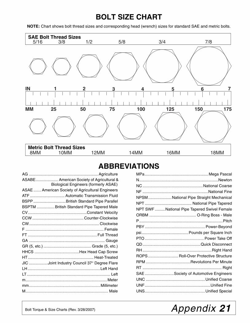
BOLT SIZE CHARTNOTE: Chart shows bolt thread sizes and corresponding head (wrench) sizes for standard SAE and metric bolts.
ABBREVIATIONSAG .............................................................. AgricultureASABE.................... American Society of Agricultural &
Biological Engineers (formerly ASAE)ASAE ....... American Society of Agricultural EngineersATF ............................... Automatic Transmission FluidBSPP .............................British Standard Pipe ParallelBSPTM ................British Standard Pipe Tapered MaleCV.....................................................Constant VelocityCCW .............................................. Counter-ClockwiseCW............................................................... ClockwiseF ...................................................................... FemaleFT .............................................................. Full ThreadGA .................................................................... GaugeGR (5, etc.) ........................................... Grade (5, etc.)HHCS ........................................Hex Head Cap ScrewHT........................................................... Heat-TreatedJIC .................Joint Industry Council 37° Degree FlareLH .................................................................Left HandLT........................................................................... Leftm......................................................................... Metermm................................................................MillimeterM.......................................................................... Male
MPa.........................................................Mega Pascal
N.......................................................................Newton
NC ......................................................National Coarse
NF ...........................................................National Fine
NPSM.....................National Pipe Straight Mechanical
NPT .......................................... National Pipe Tapered
NPT SWF .........National Pipe Tapered Swivel Female
ORBM .......................................... O-Ring Boss - Male
P...........................................................................Pitch
PBY ...................................................... Power-Beyond
psi..........................................Pounds per Square Inch
PTO..................................................... Power Take Off
QD....................................................Quick Disconnect
RH ..............................................................Right Hand
ROPS ........................... Roll-Over Protective Structure
RPM ........................................Revolutions Per Minute
RT ....................................................................... Right
SAE ..........................Society of Automotive Engineers
UNC .....................................................Unified Coarse
UNF...........................................................Unified Fine
UNS......................................................Unified Special
5/16 3/8 1/2 5/8 3/4 7/8SAE Bolt Thread Sizes
MM 25 50 75 100 125 150 175
IN 1 7
Metric Bolt Thread Sizes8MM 18MM14MM12MM10MM 16MM
2 3 4 5 6
22 Quick Coupler Quick Coupler Chart (Rev. 5/15/2006)
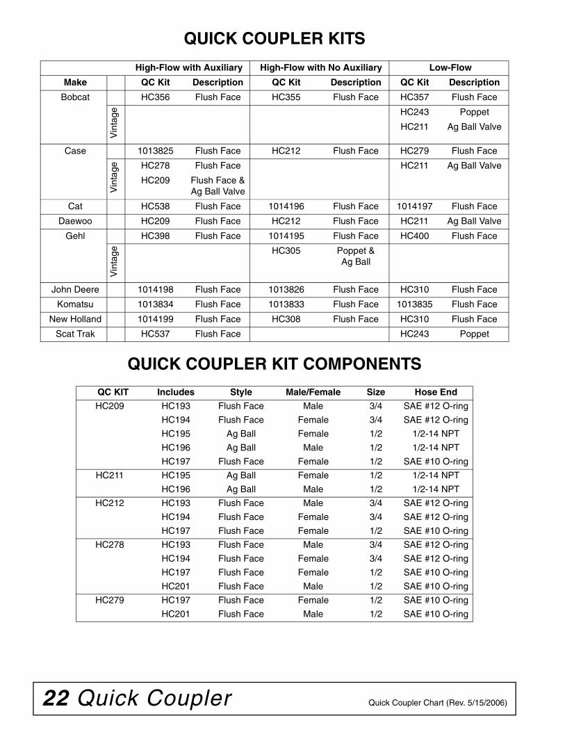
QUICK COUPLER KITS
QUICK COUPLER KIT COMPONENTS
High-Flow with Auxiliary High-Flow with No Auxiliary Low-Flow
Make QC Kit Description QC Kit Description QC Kit Description
Bobcat HC356 Flush Face HC355 Flush Face HC357 Flush Face
Vin
tage HC243 Poppet
HC211 Ag Ball Valve
Case 1013825 Flush Face HC212 Flush Face HC279 Flush Face
Vin
tage HC278 Flush Face HC211 Ag Ball Valve
HC209 Flush Face & Ag Ball Valve
Cat HC538 Flush Face 1014196 Flush Face 1014197 Flush Face
Daewoo HC209 Flush Face HC212 Flush Face HC211 Ag Ball Valve
Gehl HC398 Flush Face 1014195 Flush Face HC400 Flush Face
Vin
tage HC305 Poppet &
Ag Ball
John Deere 1014198 Flush Face 1013826 Flush Face HC310 Flush Face
Komatsu 1013834 Flush Face 1013833 Flush Face 1013835 Flush Face
New Holland 1014199 Flush Face HC308 Flush Face HC310 Flush Face
Scat Trak HC537 Flush Face HC243 Poppet
QC KIT Includes Style Male/Female Size Hose End
HC209 HC193 Flush Face Male 3/4 SAE #12 O-ring
HC194 Flush Face Female 3/4 SAE #12 O-ring
HC195 Ag Ball Female 1/2 1/2-14 NPT
HC196 Ag Ball Male 1/2 1/2-14 NPT
HC197 Flush Face Female 1/2 SAE #10 O-ring
HC211 HC195 Ag Ball Female 1/2 1/2-14 NPT
HC196 Ag Ball Male 1/2 1/2-14 NPT
HC212 HC193 Flush Face Male 3/4 SAE #12 O-ring
HC194 Flush Face Female 3/4 SAE #12 O-ring
HC197 Flush Face Female 1/2 SAE #10 O-ring
HC278 HC193 Flush Face Male 3/4 SAE #12 O-ring
HC194 Flush Face Female 3/4 SAE #12 O-ring
HC197 Flush Face Female 1/2 SAE #10 O-ring
HC201 Flush Face Male 1/2 SAE #10 O-ring
HC279 HC197 Flush Face Female 1/2 SAE #10 O-ring
HC201 Flush Face Male 1/2 SAE #10 O-ring

Quick Coupler 23Quick Coupler Chart (Rev. 5/15/2006)
QUICK COUPLER KIT COMPONENTSQC KIT Includes Style Male/Female Size Hose End
HC308 HC416 Flush Face Female 5/8 SAE #12 O-ring
HC417 Flush Face Male 5/8 SAE #12 O-ring
HC418 Flush Face Male 3/8 SAE #8 O-ring
HC310 HC414 Flush Face Male 1/2 SAE #12 O-ring
HC415 Flush Face Female 1/2 SAE #12 O-ring
HC355 HC344 Flush Face Male 12 mm SAE #12 O-ring
HC345 Flush Face Female 12 mm SAE #12 O-ring
HC346 Flush Face Female 9 mm SAE #8 O-ring
HC356 HC342 Flush Face Female 7 mm SAE #6 O-ring
HC343 Flush Face Male 7 mm SAE #6 O-ring
HC344 Flush Face Male 12 mm SAE #12 O-ring
HC345 Flush Face Female 12 mm SAE #12 O-ring
HC346 Flush Face Female 9 mm SAE #8 O-ring
HC357 HC344 Flush Face Male 12 mm SAE #12 O-ring
HC345 Flush Face Female 12 mm SAE #12 O-ring
HC398 HC344 Flush Face Male 12 mm SAE #12 O-ring
HC345 Flush Face Female 12 mm SAE #12 O-ring
HC346 Flush Face Female 9 mm SAE #8 O-ring
HC400 HC344 Flush Face Male 12 mm SAE #12 O-ring
HC345 Flush Face Female 12 mm SAE #12 O-ring
HC537 HC415 Flush Face Female 1/2 SAE #12 O-ring
HC416 Flush Face Female 5/8 SAE #12 O-ring
HC417 Flush Face Male 5/8 SAE #12 O-ring
HC418 Flush Face Male 3/8 SAE #8 O-ring
HC538 HC521 Flush Face Female 16 mm SAE #12 O-ring
HC522 Flush Face Male 16 mm SAE #12 O-ring
1532994 Flush Face Female 3/4 SAE #12 O-ring
1532995 Flush Face Male 3/4 SAE #12 O-ring
1532997 Flush Face Female 1/2 SAE #8 O-ring
1013825 HC417 Flush Face Male 5/8 SAE #12 O-ring
HC418 Flush Face Male 3/8 SAE #8 O-ring
HC545 Flush Face Female 5/8 SAE #12 O-ring
HC546 Flush Face Female 1/2 SAE #10 O-ring
HC547 Flush Face Male 1/2 SAE #10 O-ring
1013826 HC343 Flush Face Male 7 mm SAE #6 O-ring
HC521 Flush Face Female 16 mm SAE #12 O-ring
HC522 Flush Face Male 16 mm SAE #12 O-ring
1013833 HC415 Flush Face Female 1/2 SAE #12 O-ring
HC521 Flush Face Female 16 mm SAE #12 O-ring
HC522 Flush Face Male 16 mm SAE #12 O-ring
(Rev. 9/22/2006)

24 Quick Coupler Quick Coupler Chart (Rev. 5/15/2006)
QUICK COUPLER KIT COMPONENTS
QC KIT Includes Style Male/Female Size Hose End
1013834 HC414 Flush Face Male 1/2 SAE #12 O-ring
HC415 Flush Face Female 1/2 SAE #12 O-ring
HC521 Flush Face Female 16 mm SAE #12 O-ring
HC522 Flush Face Male 16 mm SAE #12 O-ring
1013835 46058 Flush Face M/F Set 3/4 SAE #12 O-ring
1014195 HC344 Flush Face Male 12 mm SAE #12 O-ring
HC345 Flush Face Female 12 mm SAE #12 O-ring
HC346 Flush Face Female 9 mm SAE #8 O-ring
1014196 HC521 Flush Face Female 16 mm SAE #12 O-ring
HC522 Flush Face Male 16 mm SAE #12 O-ring
1532997 Flush Face Female 1/2 SAE #8 O-ring
1014197 1532994 Flush Face Female 3/4 SAE #12 O-ring
1532997 Flush Face Female 1/2 SAE #8 O-ring
1014198 HC343 Flush Face Male 7 mm SAE #6 O-ring
HC414 Flush Face Male 1/2 SAE #12 O-ring
HC415 Flush Face Female 1/2 SAE #12 O-ring
HC521 Flush Face Female 16 mm SAE #12 O-ring
HC522 Flush Face Male 16 mm SAE #12 O-ring
1014199 HC414 Flush Face Male 1/2 SAE #12 O-ring
HC415 Flush Face Female 1/2 SAE #12 O-ring
HC416 Flush Face Female 5/8 SAE #12 O-ring
HC417 Flush Face Male 5/8 SAE #12 O-ring
HC418 Flush Face Male 3/8 SAE #8 O-ring
(Rev. 5/26/2006)

F-3079 (Rev 11/24/2008)
Woods Equipment Company2606 South Illinois Route 2 Post Office Box 1000Oregon, Illinois 61061 USA
800-319-6637 tel800-399-6637 faxwww.WoodsEquipment.com
WARRANTY(All Models Except Mow’n MachineTM Zero-Turn Mowers and Woods BoundaryTM Utility Vehicles)
Please Enter Information Below and Save for Future Reference.
Date Purchased: ____________________________ From (Dealer): __________________________________________
Model Number: ____________________________ Serial Number: __________________________________________
Woods Equipment Company (“WOODS”) warrants this product to be free from defect in material and workmanship. Except as otherwise setforth below, the duration of this Warranty shall be for TWELVE (12) MONTHS COMMENCING ON THE DATE OF DELIVERY OF THEPRODUCT TO THE ORIGINAL PURCHASER.
Woods backhoe models BH70-X, BH80-X, and BH90-X are warranted for two (2) years from the date of delivery to the original purchaser.
The warranty periods for specific parts or conditions are listed below:
Under no circumstances will this Warranty apply in the event that the product, in the good faith opinion of WOODS, has been subjected toimproper operation, improper maintenance, misuse, or an accident. This Warranty does not apply in the event that the product has beenmaterially modified or repaired by someone other than WOODS, a WOODS authorized dealer or distributor, and/or a WOODS authorizedservice center. This Warranty does not cover normal wear or tear, or normal maintenance items. This Warranty also does not cover repairs madewith parts other than those obtainable through WOODS.
This Warranty is extended solely to the original purchaser of the product. Should the original purchaser sell or otherwise transfer this product toa third party, this Warranty does not transfer to the third party purchaser in any way. There are no third party beneficiaries of this Warranty.
WOODS makes no warranty, express or implied, with respect to engines, batteries, tires or other parts or accessories not manufactured byWOODS. Warranties for these items, if any, are provided separately by their respective manufacturers.
WOODS’ obligation under this Warranty is limited to, at WOODS’ option, the repair or replacement, free of charge, of the product if WOODS,in its sole discretion, deems it to be defective or in noncompliance with this Warranty. The product must be returned to WOODS with proofof purchase within thirty (30) days after such defect or noncompliance is discovered or should have been discovered, routed through thedealer and distributor from whom the purchase was made, transportation charges prepaid. WOODS shall complete such repair orreplacement within a reasonable time after WOODS receives the product. THERE ARE NO OTHER REMEDIES UNDER THISWARRANTY. THE REMEDY OF REPAIR OR REPLACEMENT IS THE SOLE AND EXCLUSIVE REMEDY UNDER THISWARRANTY.
THERE ARE NO WARRANTIES WHICH EXTEND BEYOND THE DESCRIPTION ON THE FACE OF THIS WARRANTY. WOODSMAKES NO OTHER WARRANTY, EXPRESS OR IMPLIED, AND WOODS SPECIFICALLY DISCLAIMS ANY IMPLIED WARRANTYOF MERCHANTABILITY AND/OR ANY IMPLIED WARRANTY OF FITNESS FOR A PARTICULAR PURPOSE.
WOODS shall not be liable for any incidental or consequential losses, damages or expenses, arising directly or indirectly from theproduct, whether such claim is based upon breach of contract, breach of warranty, negligence, strict liability in tort or any other legaltheory. Without limiting the generality of the foregoing, Woods specifically disclaims any damages relating to (i) lost profits, business,revenues or goodwill; (ii) loss of crops; (iii) loss because of delay in harvesting; (iv) any expense or loss incurred for labor, supplies, substitutemachinery or rental; or (v) any other type of damage to property or economic loss.
This Warranty is subject to any existing conditions of supply which may directly affect WOODS’ ability to obtain materials or manufacturereplacement parts.
No agent, representative, dealer, distributor, serviceperson, salesperson, or employee of any company, including without limitation, WOODS,its authorized dealers, distributors, and service centers, is authorized to alter, modify, or enlarge this Warranty.
Answers to any questions regarding warranty service and locations may be obtained by contacting:
Part or Condition Warranted
Model Number Duration (from date of delivery to the original purchaser)
Gearbox components
BW1260, BW1620, BW1800, BW2400 8 years
BW240HD 7 years
BB48X, BB60X, BB72X, BB84X, BB600X, BB720X, BB840X, BB6000X, BB7200X,BB8400X, DS1260, DSO1260, DS1440, TS1680, BW126-3, BW180-3, BW240 6 years
PHD25, PHD35, PHD65, PHD95, 2162, 3240, DS96, DS120, RCC42, RM550-2,RM660-2, RM990-3, PRD6000, PRD7200, PRD8400, 7144RD-2, 9180RD-2,9204RD-2, S15CD, S20CD, S22CD, S25CD, S27CD
5 years
RDC54, RD60, RD72, TBW150C 3 years (1 year if used in rental or commercial applications)
Blade spindles
RM550-2, RM660-2, RM990-3, PRD6000, PRD7200, PRD8400, 7144RD-2, 9180RD-2,9204RD-2 3 years
Rust-through BB600, BB720, BB840, BB6000, BB7200, BB8400, BW126-3, BW180-3, BW1260,BW1800, BW240, BW240HD, 2162, 3240, DS1260, DSO1260, DS1440, TS1680 10 years

F-8494 (Rev. 6/23/2005)
Woods Equipment Company2606 South Illinois Route 2 Post Office Box 1000Oregon, Illinois 61061
800-319-6637 tel800-399-6637 faxwww.WoodsEquipment.com
©2003 Woods Equipment Company. All rights reserved. WOODS and the Woods logo are trademarks of Woods Equipment Company. All othertrademarks, trade names, or service marks not owned by Woods Equipment Company that appear in this manual are the property of their respectivecompanies or mark holders. Specifications subject to change without notice.
WARRANTY(Replacement Parts For All Models Except Mow’n MachineTM
Zero-Turn Mowers and Woods BoundaryTM Utility Vehicles)
Woods Equipment Company (“WOODS”) warrants this product to be free from defect in material andworkmanship for a period of ninety (90) days from the date of delivery of the product to the original purchaserwith the exception of V-belts, which will be free of defect in material and workmanship for a period of 12 months.
Under no circumstances will this Warranty apply in the event that the product, in the good faith opinion ofWOODS, has been subjected to improper operation, improper maintenance, misuse, or an accident. This Warrantydoes not cover normal wear or tear, or normal maintenance items.
This Warranty is extended solely to the original purchaser of the product. Should the original purchaser sell orotherwise transfer this product to a third party, this Warranty does not transfer to the third party purchaser in anyway. There are no third party beneficiaries of this Warranty.
WOODS’ obligation under this Warranty is limited to, at WOODS’ option, the repair or replacement, free ofcharge, of the product if WOODS, in its sole discretion, deems it to be defective or in noncompliance with thisWarranty. The product must be returned to WOODS with proof of purchase within thirty (30) days aftersuch defect or noncompliance is discovered or should have been discovered, routed through the dealer anddistributor from whom the purchase was made, transportation charges prepaid. WOODS shall completesuch repair or replacement within a reasonable time after WOODS receives the product. THERE ARE NOOTHER REMEDIES UNDER THIS WARRANTY. THE REMEDY OF REPAIR OR REPLACEMENT IS THESOLE AND EXCLUSIVE REMEDY UNDER THIS WARRANTY.
THERE ARE NO WARRANTIES WHICH EXTEND BEYOND THE DESCRIPTION ON THE FACE OF THISWARRANTY. WOODS MAKES NO OTHER WARRANTY, EXPRESS OR IMPLIED, AND WOODSSPECIFICALLY DISCLAIMS ANY IMPLIED WARRANTY OF MERCHANTABILITY AND/OR ANYIMPLIED WARRANTY OF FITNESS FOR A PARTICULAR PURPOSE.
WOODS shall not be liable for any incidental or consequential losses, damages or expenses, arising directlyor indirectly from the product, whether such claim is based upon breach of contract, breach of warranty,negligence, strict liability in tort or any other legal theory. Without limiting the generality of the foregoing,Woods specifically disclaims any damages relating to (i) lost profits, business, revenues or goodwill; (ii) loss ofcrops; (iii) loss because of delay in harvesting; (iv) any expense or loss incurred for labor, supplies, substitutemachinery or rental; or (v) any other type of damage to property or economic loss.
This Warranty is subject to any existing conditions of supply which may directly affect WOODS’ ability to obtainmaterials or manufacture replacement parts.
No agent, representative, dealer, distributor, service person, salesperson, or employee of any company, includingwithout limitation, WOODS, its authorized dealers, distributors, and service centers, is authorized to alter, modify,or enlarge this Warranty.
Answers to any questions regarding warranty service and locations may be obtained by contacting: