alkon 50-70c
TRANSCRIPT
COMPACT POWER
ALKON 50 -70 C
professional
ALKON 50 C -70 C
ALKON 50 C
ALKON 70 C
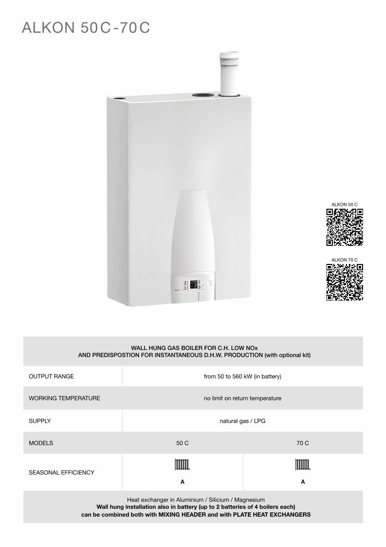
WALL HUNG GAS BOILER FOR C.H. LOW NOxAND PREDISPOSTION FOR INSTANTANEOUS D.H.W. PRODUCTION (with optional kit)
OUTPUT RANGE from 50 to 560 kW (in battery)
WORKING TEMPERATURE no limit on return temperature
SUPPLY natural gas / LPG
MODELS 50 C 70 C
SEASONAL EFFICIENCY
A A
Heat exchanger in Aluminium / Silicium / MagnesiumWall hung installation also in battery (up to 2 batteries of 4 boilers each)
can be combined both with MIXING HEADER and with PLATE HEAT EXCHANGERS

PRODUCT PLUS VALUES
Ultra compact aluminium heat exchanger-condenser (Al/Si/Mg)
Up to 8 units batteries
Combustion always undercontrol, Low NOx - Class 6(premix burner and modulating fan)
Boiler operation assured even with low gas pressures(13 mbar)
Ultra flat: only 26.6 cm in depth
Manutenzione veloce e semplice
Thermoregulation Ufly P andkit Gateway P for remote connection (optional)
D.H.W. production kit
thickness
26,6 cm
EFFICENCY CLASS A
CLASS 6 Low NOx thanks to the pre-mix burner with gas-air ratio
control which offers a constant CO2 content for the whole modulation range
CERTIFICATION IN OUTPUT RANGE
EXCHANGER/CONDENSER aluminium (Al/Si/Mg)
CONTAINED DIMENSIONS height 93 cm, width 61.5 and only 26.6 in depth.
PREMIX COMBUSTION GROUP WITH CONSTANT CO2 in Al/Si/Mg alloy
MICROPROCESSOR PCB for boiler control
VERY HIGH MODULATION RATIO • 1:7 for ALKON 70 • 1:5 for ALKON 50
INTEGRAL STANDARD INTERFACE for modulating heating controllers with protocol
communication (bus-data).
COUPLING WITH A MODULATING PUMP HIGH EFFICIENCY
supplied as standard for ALKON 70
Optional manifold with additional safety devices kit
INSTANTANEOUS D.H.W. PRODUCTION KIT (optional)
It allows a large DHW production without having recourse to voluminous cylinders
PREDISPOSITION FOR IN BATTERY INSTALLATIONS (optional)
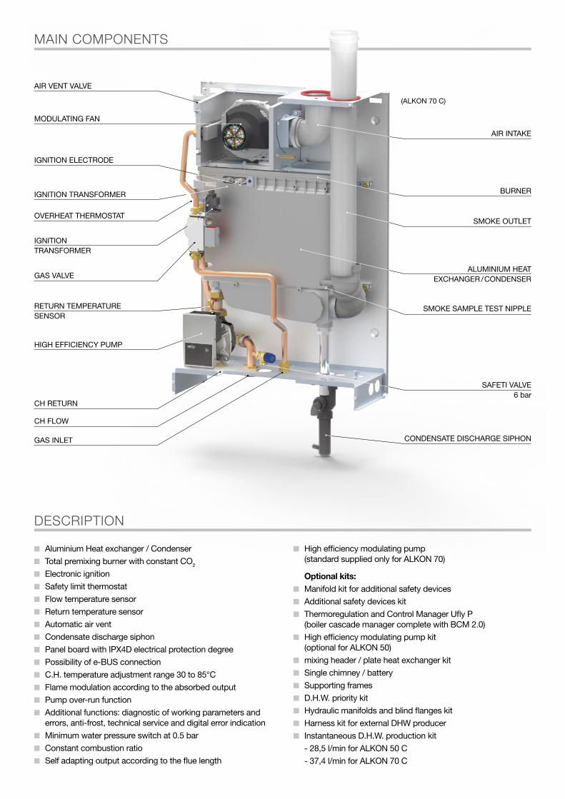
MAIN COMPONENTS
MODULATING FAN
AIR VENT VALVE
IGNITION ELECTRODE
IGNITION TRANSFORMER
OVERHEAT THERMOSTAT
GAS VALVE
RETURN TEMPERATURESENSOR
HIGH EFFICIENCY PUMP
CH RETURN
CH FLOW
SAFETI VALVE6 bar
SMOKE SAMPLE TEST NIPPLE
ALUMINIUM HEATEXCHANGER / CONDENSER
BURNER
SMOKE OUTLET
AIR INTAKE
CONDENSATE DISCHARGE SIPHONGAS INLET
IGNITIONTRANSFORMER
(ALKON 70 C)
DESCRIPTION
Aluminium Heat exchanger / Condenser
Total premixing burner with constant CO2
Electronic ignition
Safety limit thermostat
Flow temperature sensor
Return temperature sensor
Automatic air vent
Condensate discharge siphon
Panel board with IPX4D electrical protection degree
Possibility of e-BUS connection
C.H. temperature adjustment range 30 to 85°C
Flame modulation according to the absorbed output
Pump over-run function
Additional functions: diagnostic of working parameters and errors, anti-frost, technical service and digital error indication
Minimum water pressure switch at 0.5 bar
Constant combustion ratio
Self adapting output according to the flue length
High efficiency modulating pump (standard supplied only for ALKON 70)
Optional kits: Manifold kit for additional safety devices
Additional safety devices kit
Thermoregulation and Control Manager Ufly P (boiler cascade manager complete with BCM 2.0)
High efficiency modulating pump kit (optional for ALKON 50)
mixing header / plate heat exchanger kit
Single chimney / battery
Supporting frames
D.H.W. priority kit
Hydraulic manifolds and blind flanges kit
Harness kit for external DHW producer
Instantaneous D.H.W. production kit
- 28,5 l/min for ALKON 50 C
- 37,4 l/min for ALKON 70 C

THE CONTROL PANEL (standard supplied)
KIT CONTROL MANAGER Ufly P (optional)
KIT CONTROL PANEL Ufly P (optional)
Required to manage systems withup to 8 battery boilers.
Composed by:- Viewer / Programmer Ufly P- Cascade manager card BCM 2.0- Power pack 24 V- Outdoor temperature sensor- D.H.W. temperature sensor
Ufly P/Thermoregulation dialogue window SHC or Multifunction card installation manager BCM 2.0 cascade manager card (up to 8 units)
SHC SHC SHC SHC
BCM 2.0
BCM 2.0Ufly P Sonda temp. esterna Sonda temp. bollitoreAlimentatore
New and powerful interface for the simplified management of professional boilers
Ufly P can be inserted in the control panel, equipped with backlit TFT touch screen Display.The thermoregulation functions allow the hourly weekly scheduling up to a maximum of 12 heating circuits completely independent and of a Domestic Hot Water storage tank (by means of optional SHC cards).
Ufly P checks the BMM (Burner Module Manager) for the management of the single thermal element. The regulation of the heating zones and, more generally, of all types of loads, is done through optional multifunction cards, called SHC (Slave Heating Controller) for the circuits CH, DHW and the auxiliary resources (timed relays, solar accumulators).
Telemanagement
Alternatively, there are available 2 different communication protocols: eBUS and Modbus, intended for connection to different control devices.
Acquisition of operational information of all the connected devices
Parameters Setting / Changing of each module
Diagnostic management: alarm Acquisition and Reset
Gateway: allows the conversion of the Modbus / eBUS protocol to access all resources connected to the local eBUS
Included: Outdoor temperature sensor
Mounted: Flow temperature sensor, return temperature sensor.
(opzionale)
DHW set key
Central heatingadjustment key
Temperaturedecrease key
Flexibility of the controls. The control panel is equipped with an alphanumerical display with 6 pre-selection keys, which enable the user to view the following information:1. Boiler operation
• boiler status; flow and return temperature;• current error code;
2. User’s parameters• working temperature setting;• on/off central heating;
3. Service parameters with access code• maximum working temperature setting;• selection of thermostat: on/off room thermostat, remote control, on/off or modulating pump;• pump overrun time;• fan ignition speed;
4. Data readout• global flow and return temperatures;• D.H.W. temperature (if a D.H.W. storage tank is present)
Temperature increase key
Display
CH selection key:Stand-by / Central heating
Reset key/Error code display
BOILER PUMP
OUTDOOR TEMPERATURESENSOR
BOILER PUMP
E BUS
BCM 2.0
POSSIBLESYSTEM PUMP
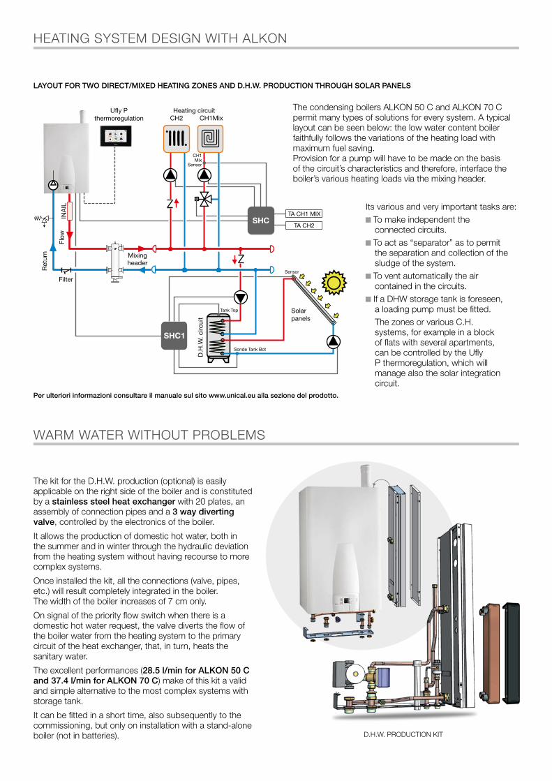
Its various and very important tasks are: To make independent the connected circuits.
To act as “separator” as to permit the separation and collection of the sludge of the system.
To vent automatically the air contained in the circuits.
If a DHW storage tank is foreseen, a loading pump must be fitted.
The zones or various C.H. systems, for example in a block of flats with several apartments, can be controlled by the Ufly P thermoregulation, which will manage also the solar integration circuit.
LAYOUT FOR TWO DIRECT/MIXED HEATING ZONES AND D.H.W. PRODUCTION THROUGH SOLAR PANELS
The kit for the D.H.W. production (optional) is easily applicable on the right side of the boiler and is constituted by a stainless steel heat exchanger with 20 plates, an assembly of connection pipes and a 3 way diverting valve, controlled by the electronics of the boiler.
It allows the production of domestic hot water, both in the summer and in winter through the hydraulic deviation from the heating system without having recourse to more complex systems.
Once installed the kit, all the connections (valve, pipes, etc.) will result completely integrated in the boiler. The width of the boiler increases of 7 cm only.
On signal of the priority flow switch when there is a domestic hot water request, the valve diverts the flow of the boiler water from the heating system to the primary circuit of the heat exchanger, that, in turn, heats the sanitary water.
The excellent performances (28.5 l/min for ALKON 50 C and 37.4 l/min for ALKON 70 C) make of this kit a valid and simple alternative to the most complex systems with storage tank.
It can be fitted in a short time, also subsequently to the commissioning, but only on installation with a stand-alone boiler (not in batteries).
HEATING SYSTEM DESIGN WITH ALKON
WARM WATER WITHOUT PROBLEMS
The condensing boilers ALKON 50 C and ALKON 70 C permit many types of solutions for every system. A typical layout can be seen below: the low water content boiler faithfully follows the variations of the heating load with maximum fuel saving.Provision for a pump will have to be made on the basis of the circuit’s characteristics and therefore, interface the boiler’s various heating loads via the mixing header.
Ufly Pthermoregulation
Heating circuitCH2 CH1Mix
D.H
.W. c
ircui
t
Tank Top
CH1Mix
Sensor
Sonde Tank Bot
Sensor
Solarpanels
Mixingheader
TA CH1 MIX
Flow
Ret
urn
Filter
SHC1
SHCTA CH2
Per ulteriori informazioni consultare il manuale sul sito www.unical.eu alla sezione del prodotto.
D.H.W. PRODUCTION KIT

1
4
7
Min
1 - SUPPORTING FRAME FOR ONE MODULE
2 - MODULATING PUMP high efficiency (optional for. ALKON 50: to be ordered separately)
3 - KIT CONTROL PANEL Ufly P composed of: thermoregulation Ufly P, Outdoor temp. sensor
4 - MIXING HEADER KIT (maximum flow rate 6 m3/h)
5 - ADDITIONAL SAFETY DEVICES COLLECTOR KIT
6 - ADDITIONAL SAFETY DEVICES KIT composed of: 3-way cock 1/2”, pressure gauge R 3/8, R 1/2 bulb holders (2x), 100°C H.L. thermostat, 5 bar safety max pressure switch, thermometer, shock absorber for pressure gauge.
7 - COLLECTORS KIT composed of: Ballstop valves, 3 way valve, Flow collector, Return collector, Return pipe connection, Differential pressure switch, Flow pipe connection + differential pressure switch
8 - BLIND FLANGES KIT
COMPONENTS (optional)
NOTE: the gas feeding pipes are not supplied.
4
6
5
7
3
21
8
COMPOSITION SINGLE BOILER + PRIMARY RING
Available in combination with PLATE HEAT EXCHANGERS
REGULATION ACCESSORIES (optional)
- SHC MULTIFUNCTION MODULE (for zones management) + 3 control probes (it is possible to drive up to a maximum of 4 SHC cards)
- NTC sensor for SHC Module
- Probe PT 1000 for management of solar collectors
- KIT GATEWAY P for Ufly P remote connection
BATTERIES FOR LARGE SIZE INTALLATIONS
ALKON 50 C AND 70 C EFFICIENCY
Output (kW)
105
106
107
Effi
cien
cy %
(Hi)
Output sharing with 4 x 50 kW modules in cascade
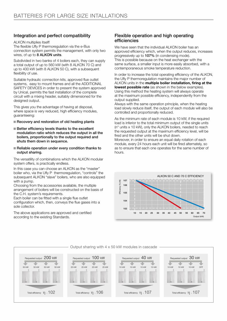
Flexible operation and high operating efficiencies We have seen that the individual ALKON boiler has an approved efficiency which, when the output reduces, increases progressively up to 107% (in condensing mode).This is possible because on the heat exchanger with the same surface, a smaller input is more easily absorbed, with a contemporaneous smoke temperature reduction.
In order to increase the total operating efficiency of the ALKON, the Ufly P thermoregulation maintains the major number of ALKON units in the multiple boiler installation, firing at the lowest possible rate (as shown in the below examples).Using this method the heating system will always operate at the maximum possible efficiency, independently from the output supplied.Always with the same operation principle, when the heating load slowly reduce itself, the output of each module will also be controlled and proportionally reduced.
As the minimum rate of each module is 10 kW, if the required load is inferior to the total minimum output of the single units (n° units x 10 kW), only the ALKON boilers, needed to reach the requested output at the maximum efficiency level, will be fired and the other units will be shut down.Moreover, in order to ensure an equal daily rotation of each module, every 24 hours each unit will be fired alternately, so as to ensure that each one operates for the same number of hours.
Integration and perfect compatibilityALKON multiplies itself!The flexible Ufly P thermoregulation via the e-Bus connection system permits the management, with only two wires, of up to 8 ALKON units.
Subdivided in two banks of 4 boilers each, they can supply a total output of up to 560 kW (with 8 ALKON 70 C) and up to 400 kW (with 8 ALKON 50 C), with a subsequent flexibility of use.
Suitable hydraulic connection kits, approved flue outlet systems, easy to mount frames and all the ADDITIONAL SAFETY DEVICES in order to present the system approved by Unical, permits the fast installation of the complete circuit with a mixing header, suitably dimensioned for the designed output.
This gives you the advantage of having at disposal, where space is very reduced, high efficiency modules, guaranteeing:
Recovery and restoration of old heating plants
Better efficiency levels thanks to the excellent modulation ratio which reduces the output in all the boilers, proportionally to the output required and shuts them down in sequence.
Reliable operation under every condition thanks to output sharing.
The versatility of combinations which the ALKON modular system offers, is practically endless.In this case you can choose an ALKON as the “master” boiler who, via the Ufly P thermoregulation, “controls” the subsequent ALKON “slave” boilers, who are also equipped with a pump.Choosing from the accessories available, the multiple arrangement of boilers will be constructed on the basis of the C.H. system’s requirements.Each boiler can be fitted with a single flue outlet configuration which, then, conveys the flue gases into a sole collector.
The above applications are approved and certified according to the existing Standards.
50 kW 50 kW 50 kW 50 kW 25 kW 25 kW 25 kW 25 kW 10 kW 10 kW 10 kW 10 kW 10 kW 10 kW 10 kW OFF
107 107
Requested output 40 kWRequested output 100 kWRequested output 200 kW Requested output 30 kW
Total efficiency Total efficiency Total efficiency Total efficiency
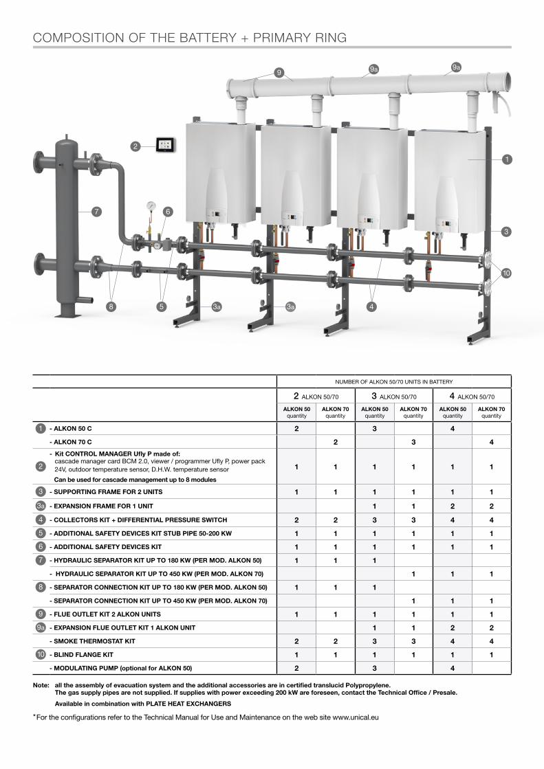
COMPOSITION OF THE BATTERY + PRIMARY RING
2
3a
1
10
9 9a 9a
48 5 3a
7 6
3
NUMBER OF ALKON 50/70 UNITS IN BATTERY
2 ALKON 50/70 3 ALKON 50/70 4 ALKON 50/70
ALKON 50quantity
ALKON 70quantity
ALKON 50quantity
ALKON 70quantity
ALKON 50quantity
ALKON 70quantity
1 - ALKON 50 C 2 3 4
- ALKON 70 C 2 3 4
2
- Kit CONTROL MANAGER Ufly P made of:cascade manager card BCM 2.0, viewer / programmer Ufly P, power pack 24V, outdoor temperature sensor, D.H.W. temperature sensor
Can be used for cascade management up to 8 modules
1 1 1 1 1 1
3 - SUPPORTING FRAME FOR 2 UNITS 1 1 1 1 1 1
3a - EXPANSION FRAME FOR 1 UNIT 1 1 2 2
4 - COLLECTORS KIT + DIFFERENTIAL PRESSURE SWITCH 2 2 3 3 4 4
5 - ADDITIONAL SAFETY DEVICES KIT STUB PIPE 50-200 KW 1 1 1 1 1 1
6 - ADDITIONAL SAFETY DEVICES KIT 1 1 1 1 1 1
7 - HYDRAULIC SEPARATOR KIT UP TO 180 KW (PER MOD. ALKON 50) 1 1 1
- HYDRAULIC SEPARATOR KIT UP TO 450 KW (PER MOD. ALKON 70) 1 1 1
8 - SEPARATOR CONNECTION KIT UP TO 180 KW (PER MOD. ALKON 50) 1 1 1
- SEPARATOR CONNECTION KIT UP TO 450 KW (PER MOD. ALKON 70) 1 1 1
9 - FLUE OUTLET KIT 2 ALKON UNITS 1 1 1 1 1 1
9a - EXPANSION FLUE OUTLET KIT 1 ALKON UNIT 1 1 2 2
- SMOKE THERMOSTAT KIT 2 2 3 3 4 4
10 - BLIND FLANGE KIT 1 1 1 1 1 1
- MODULATING PUMP (optional for ALKON 50) 2 3 4
*For the configurations refer to the Technical Manual for Use and Maintenance on the web site www.unical.eu
Note: all the assembly of evacuation system and the additional accessories are in certified translucid Polypropylene. The gas supply pipes are not supplied. If supplies with power exceeding 200 kW are foreseen, contact the Technical Office / Presale.
Available in combination with PLATE HEAT EXCHANGERS

DIMENSIONS AND TECHNICAL DATA
Key:
R - Heating system return (G1” for mod. 50, G1¼” for mod. 70)M - Heating system flow (G1” for mod. 50, G1¼” for mod. 70)G - Gas inlet (G ¾”)
Scond - Condensation drainA - Air SuctionS - Exhaust Smoke
VIEW FROM ABOVESIDE VIEWFRONT VIEW
VIEW FROM BELOW
430 107
521 971
78
662
AS
Ø 80
Ø 80
85 110 110 132 178
87
R M GS.cond
430 107
521 971
78
662
AS
Ø 80
Ø 80
85 110 110 132 178
87
R M GS.cond
615 70 266
930
KIT A.C.S.(opzionale)
ALKON Net Weightkg
Gross Weight (with packaging)kg
50 C 50 55
70 C 58,4 64
DATA ACCORDING TO ErP DIRECTIVE ALKON 50 C ALKON 70 C
NOMINAL HEAT OUTPUT Pn kW 47 66
SEASONAL SPACE HEATING ENERGY EFFICIENCY ηs % 93 93
SEASONAL EFFICIENCY CLASS IN HEATING MODE A A
FOR CH ONLY AND COMBINATION BOILERS: USEFUL HEAT OUTPUT
USEFUL HEAT OUTPUT in high temperature regime (Tr 60 °C / Tm 80 °C) P4 kW 47 66
USEFUL EFFICIENCY AT NOM. HEAT OUTPUTin high-temperature regime (Tr 60°C / Tm 80°C) η4 % 93 93
USEFUL HEAT OUTPUT AT 30% OF NOM. HEAT OUTPUT in low-temperature regime (Tr 30°C) P1 kW A A
USEFUL EFFICIENCY AT 30% OF NOM. HEAT OUTPUTin low-temperature regime (Tr 30 °C) η1 % 97.1 97.3
RANGE-RATED BOILER: YES / NO NO NO
AUXILIARY ELECTRICITY CONSUMPTION
AT FULL LOAD elmax kW 0.203 0.267
AT PART LOAD elmin kW 0.162 0.172
IN STAND-BY MODE PSB kW 0.005 0.005
OTHER ITEMS
STAND-BY HEAT LOSS Pstby kW 0.151 0.151
EMISSIONS OF NITROGEN OXIDES referred to NCV & (GCV) NOx mg/kWh 45 (41) 46 (42)
CONSUMPTION OF ANNUAL ELECTRICITY QHE GJ 92 120
FOR CH & DHW PRODUCTION BOILERS
DECLARED LOAD PROFILE - -
ENERGY EFFICIENCY IN DHW PRODUCTION MODE ηWH % - -
DAILY ELECTRICITY CONSUMPTION Qelec kWh - -
DAILY FUEL CONSUMPTIONL Qfuel kWh - -
INSIDE SOUND POWER LEVEL Lwa dB(A) 60 63
SEASONAL EFFICIENCY CLASS IN DHW PRODUCTION MODE - -
Ed.
n°
1 -
06/2
020
cod
. 319
19
ELECTRICAL, HYDRAULIC, INSTALLATION DIAGRAMS AND CONTROLLERS can be unloaded from the web site www.unical.eu at the page of the product
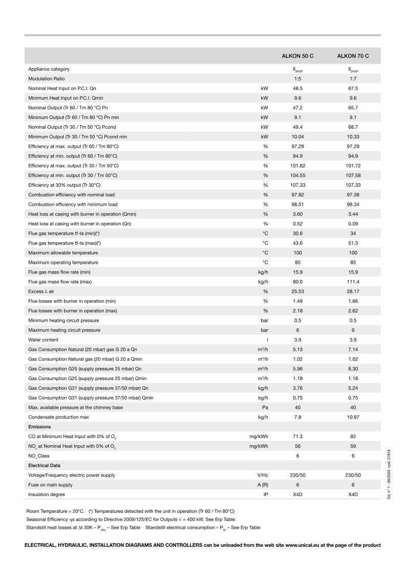
ALKON 50 C ALKON 70 C
Appliance category II2H3P II2H3P
Modulation Ratio 1:5 1:7
Nominal Heat Input on P.C.I. Qn kW 48.5 67.5
Minimum Heat Input on P.C.I. Qmin kW 9.6 9.6
Nominal Output (Tr 60 / Tm 80 °C) Pn kW 47.2 65.7
Minimum Output (Tr 60 / Tm 80 °C) Pn min kW 9.1 9.1
Nominal Output (Tr 30 / Tm 50 °C) Pcond kW 49.4 68.7
Minimum Output (Tr 30 / Tm 50 °C) Pcond min kW 10.04 10.33
Efficiency at max. output (Tr 60 / Tm 80°C) % 97.29 97.29
Efficiency at min. output (Tr 60 / Tm 80°C) % 94.9 94.9
Efficiency at max. output (Tr 30 / Tm 50°C) % 101.82 101.72
Efficiency at min. output (Tr 30 / Tm 50°C) % 104.55 107.58
Efficiency at 30% output (Tr 30°C) % 107.33 107.33
Combustion efficiency with nominal load % 97.82 97.38
Combustion efficiency with minimum load % 98.51 98.34
Heat loss at casing with burner in operation (Qmin) % 3.60 3.44
Heat loss at casing with burner in operation (Qn) % 0.52 0.09
Flue gas temperature tf-ta (min)(*) °C 30.6 34
Flue gas temperature tf-ta (max)(*) °C 43.6 51.3
Maximum allowable temperature °C 100 100
Maximum operating temperature °C 85 85
Flue gas mass flow rate (min) kg/h 15.9 15.9
Flue gas mass flow rate (max) kg/h 80.0 111.4
Excess λ air % 25.53 28.17
Flue losses with burner in operation (min) % 1.49 1.66
Flue losses with burner in operation (max) % 2.18 2.62
Minimum heating circuit pressure bar 0.5 0.5
Maximum heating circuit pressure bar 6 6
Water content l 3.9 3.9
Gas Consumption Natural (20 mbar) gas G 20 a Qn m3/h 5.13 7.14
Gas Consumption Natural gas (20 mbar) G 20 a Qmin m3/h 1.02 1.02
Gas Consumption G25 (supply pressure 25 mbar) Qn m3/h 5.96 8.30
Gas Consumption G25 (supply pressure 25 mbar) Qmin m3/h 1.18 1.18
Gas Consumption G31 (supply pressure 37/50 mbar) Qn kg/h 3.76 5.24
Gas Consumption G31 (supply pressure 37/50 mbar) Qmin kg/h 0.75 0.75
Max. available pressure at the chimney base Pa 40 40
Condensate production max kg/h 7.8 10.87
Emissions
CO at Minimum Heat Input with 0% of O2 mg/kWh 71.3 82
NOx at Nominal Heat Input with 0% of O2 mg/kWh 56 59
NOx Class 6 6
Electrical Data
Voltage/Frequency electric power supply V/Hz 230/50 230/50
Fuse on main supply A (R) 6 6
Insulation degree IP X4D X4D
Room Temperature = 20°C. (*) Temperatures detected with the unit in operation (Tr 60 / Tm 80°C)
Seasonal Efficiency ηs according to Directive 2009/125/EC for Outputs < = 400 kW. See Erp Table
Standstill heat losses at Δt 30K – Pstby – See Erp Table Standstill electrical consumption – Psb – See Erp Table

Unical AG declines any liability for the inaccuracies that may appear due to errors in transcription or printing. It also reserves the right to introducethose modifications to its products that it considers necessary or useful, without compromising the essential characteristics of the said products..
46033 castel d’ario - mantova - italy - tel. 0376 57001 - fax 0376 660556 - [email protected] - www.unical.eu