all rights reserved © 2006 copyright matsushita electric
TRANSCRIPT

ARCT1F425E_0609.ai
®
MICRO-IMAGECHECKER A200/A100 SERIES
Hardware Manual
Matsushita Electric Works, Ltd.http://www.nais-e.com/
Matsushita E
lectric Works, Ltd.
MIC
RO
-IMA
GE
CH
EC
KE
R A
200/A100 S
ER
IES
Hardw
are Manual
A200/A100 Series Hardware ManualARCT1F425E ’06.9
®
ARCT1F425E 200609-5ZTACG-M425E
Please contact ..........
Specifications are subject to change without notice. Printed in Japan.
Automation Controls Business UnitHead Office: 1048, Kadoma, Kadoma-shi, Osaka 571-8686, JapanTelephone: +81-6-6908-1050 Facsimile: +81-6-6908-5781
http://www.nais-e.com/
All Rights Reserved © 2006 COPYRIGHT Matsushita Electric Works, Ltd.
Matsushita Electric Works, Ltd.
These materials are printed on ECF pulp.These materials are printed with earth-friendly vegetable-based (soybean oil) ink.
A200 Series A100 Series
COMFLACOMRDYERRRENSTROVF
D1D2D3D4D5D6D7D8
COMSTACOMACKTYPIN1
IN4IN3IN2
IN5IN6IN7IN8
+-
CAMERA-A
MONITOR
TOOL
COM
KEYPAD
POWER
ERROR
READY
MIC
RO
-IMA
GEC
HEC
KER
A10
0
COMFLACOMRDYERRRENSTROVF
D1D2D3D4D5D6D7D8
COMSTACOMACKTYPIN1
IN4IN3IN2
IN5IN6IN7IN8
+-
CAMERA-A
CAMERA-B
MONITOR
TOOL
COM
KEYPAD
POWER
ERROR
READY
MIC
RO
-IMA
GEC
HEC
KER
A
200

WARNINGS AND CAUTIONS
To be observed at all timesRead the manual carefully before installing, running, maintaining or inspecting theequipment.This manual uses two safety flags to indicate different levels of danger.WARNING: A handling error could cause serious physical injury to an operator, and in
the worst case could even be fatal.CAUTION: A handling error could cause serious physical injury to an operator, or
damage to the equipment.
WARNING
− Always take precautions to ensure the overall safety of your system, so that thewhole system remains safe in the event of failure of this product or other externalfactor.
− Do not use this product in areas with inflammable gas. It could lead to anexplosion.
CAUTION
− To prevent abnormal exothermic heat or smoke generation, use this product atthe values less than themaximumof the characteristics and performance that areassured in these specifications.
− Do not dismantle or remodel the product. It could lead to abnormal exothermicheat or smoke generation.
− Do not touch the terminal while turning on electricity. It could lead to an electricshock.
− Donot allow foreignmatters such as liquid, flammablematerials, metals to go intothe inside of the product. It might cause exothermic heat or smoke generation.
− Do not undertake construction (such as connection and disconnection) while thepower supply is on.
− Connect the wires or connectors securely. The loose connection might causeabnormal exothermic heat or smoke generation.

GENERAL INSTRUCTIONS
Installation EnvironmentAvoid using the Micro−Imagechecker A210/A110 in the following types of locations:− Locations with direct sunlight or environmental temperatures that exceed a range
of 0°C to 50°C.− Locations with a relative humidity exceeding a range of 35%RH to 75%RH or that
are subject to condensation due to dramatic temperature fluctuations.− Locations with an atmosphere containing corrosive gases or flammable gases.− Locations that subject the main unit to direct vibration or impact.− Locations with a lot of fine particles, iron filings or salt.− Locations likely to have contact with water, oil or chemicals.− Locations with an atmosphere likely to contain organic solvents such as benzine,
paint thinner, and alcohol as well as strongly alkaline materials such as ammoniaand caustic soda.
Static ElectricityIn a dry environment, there is a risk of accumulation of static electricity, so when thereis a need to touch the equipment, users should always discharge the accumulatedstatic by touching an earthed part of the equipment first.
CleaningDo not use thinners or similar solvents, as they may dissolve parts of the unit andcause colors to run.
PowerUse an insulated power source with built in protection circuits. The controller powerunit uses non−insulted circuits, so if an irregular voltage is applied, there is a dangerthat the internal circuitry will be damaged. If you use a power source that does not useprotection circuits, supply the power via a fuse or other protective device.
Power Sequence− Arrange the power sequence so that the controller power source is turned off
before the input/ output power source.− If you turn off the input/output power source before the controller power source,
the controller unit will detect an input signal level change and may not runproperly.

Before Switching On the PowerThe following points should be checked before switching the power on to the controllerfor the first time.− Check that no extra wiring left installation, especially conductive materials, have
become attached to the board.− Confirm that the power supply wiring and I/Owiring and power supply voltage are
correct.− Firmly tighten all installation screws and terminal block screws.
Before Creating Type DataBefore creating type data, be sure to initialize the environment settings and all typesettings.
See User’s Manual for more information about initialization.
Other Instructions− Usemonitor, monitor cable, keypad, camera and camera cablemodels and serial
numbers specified by Matsushita.− Do not disassemble, modify, or change internal settings for the
Micro−Imagechecker unit or other equipment.− Setting or changing items other than those that can be set or changed, as
described in the product manual and specifications, will result in damage.− After completing all of the settings for the Micro−Imagechecker, do not connect
the personal computer used for connecting the keypad, restoring or backup, inorder to prevent malfunctioning due to noise.
− Do not perform insulation resistance or pressure resistance tests between metalareas of the power supply, input/output signal and connectors and the cameracase.
To USA Customer− Products sold by Seller are covered by the warranty and patent indemnification
provisions in its Terms and Conditions of Sale only.


i
Contents
Chapter 1 Part Names and Functions
1.1 Controller 1 − 3. . . . . . . . . . . . . . . . . . . . . . . . . . . . . . . . . . . . . . . . . . . . . . . . . . . . . . . .
1.2 A Series Camera 1 − 5. . . . . . . . . . . . . . . . . . . . . . . . . . . . . . . . . . . . . . . . . . . . . . . . . .1.2.1 Double−Speed Random Camera 1 − 5. . . . . . . . . . . . . . . . . . . . . . . . . . . .1.2.2 CS−Mount Camera 1 − 7. . . . . . . . . . . . . . . . . . . . . . . . . . . . . . . . . . . . . . . .
1.3 Camera Cable and Camera Extension Cable 1 − 8. . . . . . . . . . . . . . . . . . . . . . . . .
1.4 Keypad 1 − 9. . . . . . . . . . . . . . . . . . . . . . . . . . . . . . . . . . . . . . . . . . . . . . . . . . . . . . . . . .
Chapter 2 Installation and Wiring
2.1 Connecting Peripherals 2 − 3. . . . . . . . . . . . . . . . . . . . . . . . . . . . . . . . . . . . . . . . . . . .
2.2 Installation Environment and Mounting Space 2 − 4. . . . . . . . . . . . . . . . . . . . . . . . .
2.3 Mounting the Controller 2 − 6. . . . . . . . . . . . . . . . . . . . . . . . . . . . . . . . . . . . . . . . . . . .
2.4 Mounting the Camera 2 − 7. . . . . . . . . . . . . . . . . . . . . . . . . . . . . . . . . . . . . . . . . . . . . .
2.5 View range and Lens Selection Tables 2 − 8. . . . . . . . . . . . . . . . . . . . . . . . . . . . . . .2.5.1 ANM831 Double−Speed Random Camera 2 − 8. . . . . . . . . . . . . . . . . . . .2.5.2 ANM832 Standard Camera 2 − 9. . . . . . . . . . . . . . . . . . . . . . . . . . . . . . . . .
Chapter 3 Input/Output Terminals (Input/Output Ports)
3.1 Attaching Wires to the Terminal Blocks 3 − 3. . . . . . . . . . . . . . . . . . . . . . . . . . . . . . .
3.2 Output Terminal (Parallel Output Port) 3 − 4. . . . . . . . . . . . . . . . . . . . . . . . . . . . . . . .
3.3 Input Terminal (Parallel Input Port) 3 − 5. . . . . . . . . . . . . . . . . . . . . . . . . . . . . . . . . . .
3.4 Cautions Related to Parallel Input/Output 3 − 6. . . . . . . . . . . . . . . . . . . . . . . . . . . . .3.4.1 About Parallel Output 3 − 6. . . . . . . . . . . . . . . . . . . . . . . . . . . . . . . . . . . . . .3.4.2 About Parallel Input 3 − 7. . . . . . . . . . . . . . . . . . . . . . . . . . . . . . . . . . . . . . . .
3.5 Flash Output Sync Signal 3 − 8. . . . . . . . . . . . . . . . . . . . . . . . . . . . . . . . . . . . . . . . . .
3.6 Electric Power Wiring 3 − 10. . . . . . . . . . . . . . . . . . . . . . . . . . . . . . . . . . . . . . . . . . . .
3.7 About Grounding 3 − 12. . . . . . . . . . . . . . . . . . . . . . . . . . . . . . . . . . . . . . . . . . . . . . . .

Contents A200/A100 Hardware
ii
Chapter 4 Serial (RS−232C) Ports
4.1 Serial (RS−232C) Ports 4 − 3. . . . . . . . . . . . . . . . . . . . . . . . . . . . . . . . . . . . . . . . . . . .
4.2 COM port (Data output, VBT Ver. 2) 4 − 5. . . . . . . . . . . . . . . . . . . . . . . . . . . . . . . . .
4.3 TOOL port (VBT Ver. 2 Port) 4 − 10. . . . . . . . . . . . . . . . . . . . . . . . . . . . . . . . . . . . . .
Chapter 5 About Camera Modes
5.1 Camera Modes 5 − 3. . . . . . . . . . . . . . . . . . . . . . . . . . . . . . . . . . . . . . . . . . . . . . . . . . .
5.2 Imaging Time for the Camera Modes(for memory image display) and Resolution 5 − 4. . . . . . . . . . . . . . . . . . . . . . . . . . .
5.3 Frame Mode and Field Mode 5 − 5. . . . . . . . . . . . . . . . . . . . . . . . . . . . . . . . . . . . . . .
Chapter 6 Product Type Data Creation and Backup
6.1 Product Type Data Creation and Backup 6 − 3. . . . . . . . . . . . . . . . . . . . . . . . . . . . .
Chapter 7 General Specifications
7.1 Controller 7 − 3. . . . . . . . . . . . . . . . . . . . . . . . . . . . . . . . . . . . . . . . . . . . . . . . . . . . . . . .
7.2 Key pad 7 − 4. . . . . . . . . . . . . . . . . . . . . . . . . . . . . . . . . . . . . . . . . . . . . . . . . . . . . . . . . .
7.3 Monitor 7 − 5. . . . . . . . . . . . . . . . . . . . . . . . . . . . . . . . . . . . . . . . . . . . . . . . . . . . . . . . . .
7.4 Double−Speed Random Camera ANM831 7 − 6. . . . . . . . . . . . . . . . . . . . . . . . . . . .
7.5 CS−Mount Camera ANM832 7 − 7. . . . . . . . . . . . . . . . . . . . . . . . . . . . . . . . . . . . . . . .

ContentsA200/A100 Hardware
iii
Chapter 8 Part Numbers
8.1 Controllers 8 − 3. . . . . . . . . . . . . . . . . . . . . . . . . . . . . . . . . . . . . . . . . . . . . . . . . . . . . . .
8.2 Cameras 8 − 5. . . . . . . . . . . . . . . . . . . . . . . . . . . . . . . . . . . . . . . . . . . . . . . . . . . . . . . . .
8.3 Double−Speed Random Camera Cable 8 − 6. . . . . . . . . . . . . . . . . . . . . . . . . . . . . .
8.4 Camera Extension Cable 8 − 7. . . . . . . . . . . . . . . . . . . . . . . . . . . . . . . . . . . . . . . . . . .
8.5 Keypad 8 − 8. . . . . . . . . . . . . . . . . . . . . . . . . . . . . . . . . . . . . . . . . . . . . . . . . . . . . . . . . .
8.6 Monitor 8 − 9. . . . . . . . . . . . . . . . . . . . . . . . . . . . . . . . . . . . . . . . . . . . . . . . . . . . . . . . . .
8.7 Data Backup Software and PC Cable 8 − 10. . . . . . . . . . . . . . . . . . . . . . . . . . . . . .
8.8 Lenses and Adapter Rings 8 − 11. . . . . . . . . . . . . . . . . . . . . . . . . . . . . . . . . . . . . . . .
8.9 Lighting for Image Processing 8 − 12. . . . . . . . . . . . . . . . . . . . . . . . . . . . . . . . . . . .
Chapter 9 Dimension diagramv
9.1 Controller 9 − 3. . . . . . . . . . . . . . . . . . . . . . . . . . . . . . . . . . . . . . . . . . . . . . . . . . . . . . . .
9.2 Camera 9 − 4. . . . . . . . . . . . . . . . . . . . . . . . . . . . . . . . . . . . . . . . . . . . . . . . . . . . . . . . . .9.2.1 Double−Speed Random Camera ANM831 9 − 4. . . . . . . . . . . . . . . . . . . .9.2.2 CS−Mount Camera ANM832 9 − 4. . . . . . . . . . . . . . . . . . . . . . . . . . . . . . . .
9.3 Camera Cable and Camera Extension Cable 9 − 5. . . . . . . . . . . . . . . . . . . . . . . . .
9.4 Keypad 9 − 6. . . . . . . . . . . . . . . . . . . . . . . . . . . . . . . . . . . . . . . . . . . . . . . . . . . . . . . . . .
9.5 Monitor: ANMA810 9 − 7. . . . . . . . . . . . . . . . . . . . . . . . . . . . . . . . . . . . . . . . . . . . . . . .
9.6 Lenses 9 − 8. . . . . . . . . . . . . . . . . . . . . . . . . . . . . . . . . . . . . . . . . . . . . . . . . . . . . . . . . .
Chapter 10 Reference
10.1 Camera Pin Positions (ANM831) 10 − 3. . . . . . . . . . . . . . . . . . . . . . . . . . . . . . . . . .
10.2 Camera Pin Positions (ANM832) 10 − 4. . . . . . . . . . . . . . . . . . . . . . . . . . . . . . . . . .
Chapter 11 Manual revision history
11.1 Manual revision history 11 − 3. . . . . . . . . . . . . . . . . . . . . . . . . . . . . . . . . . . . . . . . . . .

Contents A200/A100 Hardware
iv

Chapter 1
Part Names and Functions
1.1 Controller 1 − 3. . . . . . . . . . . . . . . . . . . . . . . . . . . . . . . . . . . . . .
1.2 A Series Camera 1 − 5. . . . . . . . . . . . . . . . . . . . . . . . . . . . . . . .
1.2.1 Double−Speed Random Camera 1 − 5. . . . . . . . . .
1.2.2 CS−Mount Camera 1 − 7. . . . . . . . . . . . . . . . . . . . . .
1.3 Camera Cable and Camera Extension Cable 1 − 8. . . . . . .
1.4 Keypad 1 − 9. . . . . . . . . . . . . . . . . . . . . . . . . . . . . . . . . . . . . . . .

A200/A100 HardwarePart Names and Functions
1 − 2

Part Names and FunctionsA200/A100 Hardware
1 − 3
1.1 Controller
1.1 Controller
Weight: Around 300gSize: 40 × 120 × 50mm(Excluding protruding parts)
1
4
2
5
3
9
10
8
7
6
9
8
7
1
4
2
5
3
6
A200 A100
Names and Functions of Controller Parts
1. Operating LEDsIndicate the controller’s operating status.POWER (green) This green LED is lit when the controller is
connected to a live power source.ERROR (red) The red LED is lit when an error has occurred.READY (green) This green LED is lit when the start signal can be
input. (when ready for inspection)
2. Keypad jackProvides a connection for the operation keypad.
3. COM port (RS−232C port)Provides an RS−232C connection for an external device.
4. Tool portProvides an RS−232C connection for an external device (only VBT Ver. 2).
5. MonitorProvides a connection for a monitor.
6. Camera jackOne camera jack is provided on an A100.Two camera jacks are provided on an A200, one for camera Aand one for Camera B.

A200/A100 HardwarePart Names and Functions
1 − 4
1.1 Controller
7. Power supply24 power is required. The power supply is connected to theinput terminal block.
8. External input terminal (16 pin)Provides a connection for input from an external source.
9. External output terminal (16 pin)Provides a connection for output to an external device.The input/output terminal block is part order number 1840502 from PhoenixContact. See page 3 − 3 for details about compatible electric wiring and theterminal block.
10. DIN rail mounting leverYou can mount the controller onto a DIN rail with one easy (one−two hook) motion.
Using the Controller Correctly
− When you connect multiple cameras to an A200 controller, be sure the cameras areof the same type.
− When you connect only one camera to an A200 controller, plug it into the CameraA jack.
− Do not connect any products to the controller other than those specified by us.

Part Names and FunctionsA200/A100 Hardware
1 − 5
1.2 A Series Camera
1.2 A Series Camera
1.2.1 Double−Speed Random Camera
Weight: around 70g(camera only)Size: 29 × 31 × 54.5mm(Excluding protruding parts)
1
2
3
4
5 6
7
Names and Functions of Double−Speed Random Camera Parts
1. CameraThe camera body.
2. Lens mountA C−mount.
3. LensUse the C−mount lens together with an adapter ring as necessary. Select a lensfrom the Field of Vision and Lens Selection Table on page 2 − 8.
4. Cable connectorThe camera is connected to the controller with a camera cable having the specifiedpart number.
5. Gain fine turning knobUsed to finely adjust the camera gain.
6. DIP−SwitchesSwitches camera modes between frame and field, adjusts camera gain.
7. Metal fittingHardware used to mount the camera.

A200/A100 HardwarePart Names and Functions
1 − 6
1.2 A Series Camera
About the DIP Switches
− Gain adjustmentDIP switch 5: ON = 0 to +10dB range gain adjustment volume.
OFF = 0dB
− Potentiometer: When DIP−SW5 is ON, turning this potentiometer to the rightincreases the brightness of the image captured by the camera.
− Camera mode switchDIP switch 6: ON = frame mode
OFF = field mode
− OtherDIP switches 1 to 4, 7, 8: Normally OFF
− Settings when shippedDIP switch 5 = ON, VOL +10dB. All others are OFF.
Using the Camera Correctly
− When you connect more than one camera to an A200 controller, be sure the camerasare of the same type.
− When you connect only one camera to an A200 controller, plug it into the CameraA jack.
− Do not use products other than those specified by us for camera cables or cameraextension cables.
− Do not connect multiple camera cables or camera extension cables to one anotherto make an extension.
− Do not touch the camera’s CCD elements or lens surface. Also, be sure to cap thecamera when storing it in order to prevent smudges on the CCD elements or lenssurface.
− Change the DIP switch positions in accordance with the camera mode.
− Be very certain not to change the DIP switch settings of other DIP switches.

Part Names and FunctionsA200/A100 Hardware
1 − 7
1.2 A Series Camera
1.2.2 CS−Mount Camera
123 4
5
CS−Mount Camera: Part Names and Functions
1. CameraThe camera’s main unit.
2. Lens mountA CS−mount.
3. LensUse the C/CS−mount lens together with an adapter ring as necessary. Select a lensfrom the Field of Vision and Lens Selection Table on page 2 − 9.
4. Cable connectorThe camera is connected to the controller via this connector. If necessary, also usea camera extension cable with a part number specified by us.
5. Metal fittingHardware used to mount the camera.
Using the Camera Correctly
− When you connect multiple cameras to an A200 controller, be sure the cameras areof the same type.
− When you connect only one camera to an A200 controller, plug it into the CameraA jack.
− Do not use products other than those specified by us for camera cables or cameraextension cables.
− Do not connect multiple camera cables or camera extension cables to one anotherto make an extension.
− Do not touch the camera’s CCD elements or lens surface. Also, be sure to cap thecamera when storing it in order to prevent smudges on the CCD elements or lenssurface.

A200/A100 HardwarePart Names and Functions
1 − 8
1.3 Camera Cable and Camera Extension Cable
1.3 Camera Cable and Camera Extension Cable
21
Names and Functions of Parts
1. Connector (male):Connects the male connector to the controller.
2. Connector (female):Connects the female connector to the camera.
Using the Cable Correctly
− Do not use products other than those specified by us for camera cables or cameraextension cables.
− Do not connect multiple camera cables or camera extension cables to one anotherto make an extension.
− Do not bend camera cables unnecessarily or place loads on the connector joints.

Part Names and FunctionsA200/A100 Hardware
1 − 9
1.4 Keypad
1.4 Keypad
2, 3
1
4
C
ENTER
A B
Names and Functions of Parts
1. A, B, C buttonsCan be operated using function displayed on the screen.
2. Cursor leverMoves the cursor. Can move it in a maximum of eight directions.
3. Enter buttonConfirms an entry.
4. TerminalConnects the keypad to the A Series controller.
Operation of the Cursor lever and ENTER buttonWhen you press the cursor lever to move the cursor an ENTER may be inputerroneously. To avoid this problem, remove your finger from the cursor levermomentarily as you change cursor movement direction.
− The functions available from the keypad depend on the functions provided by thecontroller.
ENTER
Move up
Move down
Move left Move right
CursoroperationENTER
Press directly downward from above
Using the Keypad Correctly
− Avoid connecting a keypad not specified by us to the controller.

A200/A100 HardwarePart Names and Functions
1 − 10
1.4 Keypad

Chapter 2
Installation and Wiring
2.1 Connecting Peripherals 2− 3. . . . . . . . . . . . . . . . . . . . . . . . . .
2.2 Installation Environment and Mounting Space 2− 4. . . . . . .
2.3 Mounting the Controller 2− 6. . . . . . . . . . . . . . . . . . . . . . . . . .
2.4 Mounting the Camera 2− 7. . . . . . . . . . . . . . . . . . . . . . . . . . . .
2.5 View range and Lens Selection Tables 2− 8. . . . . . . . . . . . .
2.5.1 ANM831 Double−Speed RandomCamera 2− 8. . . . . . . . . . . . . . . . . . . . . . . . . . . . . . . .
2.5.2 ANM832 Standard Camera 2− 9. . . . . . . . . . . . . . .

A200/A100 HardwareInstallation and Wiring
2 − 2

Installation and WiringA200/A100 Hardware
2 − 3
2.1 Connecting Peripherals
2.1 Connecting Peripherals
Be sure to connect peripherals to the controller only when the controller power is OFF.
24VDCMonitor−Cable
Camera−Cable
Ground
Keypad
*Only one camera can be connected to the A100.
Using Peripherals Correctly
− Do not connect products not specified by us to the controller.
− Be sure to connect peripherals only when the controller power is turned OFF.Otherwise, damage could result.
− When you connect multiple cameras to an A200 controller be sure the cameras areof the same type.
− When you connect only one camera to an A200 controller plug it in to the CameraA jack.
− Avoid unintentional cable detachment by arranging the wiring so there is no weightor load on the cable connector joints.
− When unplugging a connector, be sure to grasp the connector part itself and avoidexerting unnecessary force on the cable. Also, avoid touching or allowing water tocome in contact with the connector pins.

A200/A100 HardwareInstallation and Wiring
2 − 4
2.2 Installation Environment and Mounting Space
2.2 Installation Environment and Mounting Space
Avoid Installing the Equipment in Locations with the Following Characteristics
− Where the temperature is outside the range of 0°C to 50°C.
− Where the relative humidity is outside the range of 35%RH to 75%RH.
− Where there is a danger of condensation due to sudden temperature fluctuations.
− In the presence of corrosive gas or combustible gas.
− Where dust, metal powders, or salt are present in large amounts.
− In an environment where there is a possibility that organic solvents such as benzene,paint thinner, or alcohol, or strong alkaline substances such as ammonia or causticsoda may adhere.
− Where the equipment will be subject to vibration or shock.
− In direct sunlight.
− Where there is a possibility that water, oil, or chemicals may come into direct contact.
− Where there will be a weight load placed on the main unit.
Noise Considerations
− Install the unit as far away as possible from high−voltage lines and equipment, drivelines and equipment, and other equipment that may generate large power surgeswhen it turns on or off.
− Install the unit as far away as possible from equipment such as amateur radiotransmitters.

Installation and WiringA200/A100 Hardware
2 − 5
2.2 Installation Environment and Mounting Space
Heat Dissipation
− Mount the unit in any of the following arrangements to facilitate heat dissipation.
Contact mountingis acceptable.
Do not mount the unit on top of strong heat sources such as heaters, transformers, orhigh−capacity resistors.
About Mounting Space
− When installing the unit, aim to leave at least 50mm between the controller and anynearby objects such as ducts or other equipment. Controller replacement and wiringwill be easier this way.
− When you install doors or other equipment in front of the controller’s front panelprovide at least a 100mm space between the controller and the equipment in orderto avoid noise and heat effects.
− Provide at least 100mm of space in front of the controller’s front panel to provide forthe keypad connection and wiring.
50mm or more
50mm or more
100mm or more
50mm or more

A200/A100 HardwareInstallation and Wiring
2 − 6
2.3 Mounting the Controller
2.3 Mounting the Controller
You can mount the controller either by using screws or by hooking it on a DIN rail.
Mounting the Controller on a DIN RailThe controller can be mounted on or removed from a 35mm wide DIN rail (DINEN50022) by a single easy motion.
Mounting1. Catch the controller on to the hook rail at the top of the DIN rail.2. Press the controller into position.
Removing1. Push a straight screwdriver into the mounting lever.2. Press the mounting lever downward.3. Pick up the controller to remove it.
Rail
Mounting the Controller Using ScrewsRefer to the dimension diagrams on page 9−3, and secure the controller using M3screws.

Installation and WiringA200/A100 Hardware
2 − 7
2.4 Mounting the Camera
2.4 Mounting the Camera
Mount the camera so it doesn’t wobble. You can mount the camera directly or with metalfitting. Use the dimensional diagram for reference when you mount the camera.
Using the Camera Correctly
− Connect the camera case to the internal circuit ground. When you mounted thecamera to a device with a different electric potential there is a concern that internaldamage could result, so mount it in an electrically isolated way.
− In order to eliminate the effect of within−tolerance variations of CCD mountingdimensions when the camera is mounted, be sure to verify it with an actual image.

A200/A100 HardwareInstallation and Wiring
2 − 8
2.5 View range and Lens Selection Tables
2.5 View range and Lens Selection Tables
Select the lens and extension rings from the following table in order to match theresolution or view range.
2.5.1 ANM831 Double−Speed Random Camera
Lens
View range (mm)
ANM8850 (1)f=50mm
ANB847Lf=50mm
ANB846NLANM88251f=25mm
ANB845NLANM88161(*1)
f=16mm
ANB843Lf=8.5mm
ANB842Lf=6.5mm
Resolutionµm/pixel
Verticalviewrange
Horizontalviewrange
a b a b a b a b a b a b Vertical Horizontal
1 1.1 59 178 48 178 2.1 2.12 2.1 73 89 62 89 4.2 4.23 3.2 87 59 76 59 6.3 6.24 4.3 101 44 90 44 8.3 8.35 5.3 115 36 104 36 31 18 10 107.5 8.0 150 24 139 24 49 12 16 1610 10.7 186 18 175 18 66 9 31 6 21 2112.5 13.3 221 14 210 14 84 7 42 5 26 2615 16.0 256 12 245 12 101 6 31 3120 21.3 326 9 315 9 137 2*3 76 2*2 30 1.5 42 4230 32.0 467 6 456 6 207 2*2 121 2 54 1 42 1.0 63 6240 42.6 277 2 166 1 78 1 60 0.5 83 8350 53.3 348 2 211 1 102 0.5 79 0.5 104 10475 79.9 524 1 323 1 162 0 124 0 156 156100 106.5 700 1 436 0.5 221 0 170 0 208 208150 159.8 661 0 341 0 262 0 313 312200 213.1 461 0 353 0 417 416250 266.3 580 0 445 0 521 520
Vertical view Horizontal view
a: Distance between the frontof the lens and the object
b: Adapter ringLens
Metal fitting
a: distance from end of lens to object.b: thickness of adapter ring.
NoteThe view range − lens table is designed primarily for use as afocusing guide. Use the camera itself to make the finaladjustments to focus, view range, distance to work, resolutionand any other settings which need to be made before running thesystem.Unless otherwise noted, the focus values in the chart are allinfinity.*1: a = +4mm*2: Lens focal position is near middle.*3: Lens focal position is in closest position.

Installation and WiringA200/A100 Hardware
2 − 9
2.5 View range and Lens Selection Tables
2.5.2 ANM832 Standard Camera
Lens
View range (mm)
ANM8850 (1)f=50mm
ANB847Lf=50mm
ANB846NLANM88251f=25mm
ANB845NLANM88161(*1)
f=16mm
ANB843Lf=8.5mm
Resolutionµm/pixel
Verticalviewrange
Horizontalviewrange
a b a b a b a b a b Vertical Horizontal
1 1.1 59 183 48 183 2.1 2.12 2.1 73 94 62 94 4.2 4.23 3.2 87 64 76 64 6.3 6.34 4.3 101 49 90 49 8.3 8.35 5.3 115 41 104 41 31 23 10.4 10.47.5 8.0 150 29 139 29 49 17 15.6 15.610 10.7 186 23 175 23 66 14 31 11 20.8 20.912.5 13.3 221 19 210 19 84 12 42 10 26.0 26.115 16.0 256 17 245 17 101 11 53 9 31.3 31.320 21.4 326 14 315 14 137 9 76 8 30 6.5 41.7 41.730 32.0 467 11 456 11 207 8 121 7 54 6 62.5 62.640 42.7 608 9 597 9 277 7 166 6.5 78 5.5 83.3 83.450 53.4 348 6.5 211 6 102 5.5 104.2 104.375 80.1 524 6 323 5.5 162 5.5 156.3 156.4100 106.8 700 6 436 5.5 221 5.5 208.3 208.6150 160.2 661 5.5 341 5 312.5 312.9200 213.6 886 5 461 5 416.7 417.2250 267.0 580 5 520.8 521.5300 320.4 625.0 625.8
Vertical view Horizontal view
a: Distance between the frontof the lens and the object
b: Adapter ringLens
Metal fitting
a: distance from end of lens to object.b: thickness of adapter ring.
NoteThe view range − lens table is designed primarily for use as afocusing guide. Use the camera itself to make the finaladjustments to focus, view range, distance to work, resolutionand any other settings which need to be made before running thesystem.Unless otherwise noted, the focus values in the chart are allinfinity.*1: a = +4mm

A200/A100 HardwareInstallation and Wiring
2 − 10
2.5 View range and Lens Selection Tables
Lens
View range (mm)ANB842Lf=6.5mm
ANM8808 (1)f=8mm
ANM8804 (1)f=4mm
ANM8828 (1)f=2.8mm
Resolutionµm/pixel
Verticalviewrange
Horizontalviewrange
a b a b a b a b Vertical Horizontal
1 1.1 2.1 2.12 2.1 4.2 4.23 3.2 6.3 6.34 4.3 8.3 8.35 5.3 10.4 10.47.5 8.0 15.6 15.610 10.7 20.8 20.912.5 13.3 26.0 26.115 16.0 31.3 31.320 21.4 31 1.5 41.7 41.730 32.0 42 5.5 54 1 62.5 62.640 42.7 60 5.5 76 0.5 33 0.5 83.3 83.450 53.4 79 5.5 99 0.5 44 0 104.2 104.375 80.1 124 5.5 155 0.5 73 0 45 0 156.3 156.4100 106.8 170 5 211 0 101 0 64 0 208.3 208.6150 160.2 262 5 324 0 157 0 104 0 312.5 312.9200 213.6 353 5 437 0 213 0 143 0 416.7 417.2250 267.0 445 5 549 0 270 0 183 0 520.8 521.5300 320.4 536 5 662 0 326 0 222 0 625.0 625.8
Vertical view Horizontal view
a: Distance between the frontof the lens and the object
b: Adapter ringLens
Metal fitting
a: distance from end of lens to object.b: thickness of adapter ring.
NoteThe view range − lens table is designed primarily for use as afocusing guide. Use the camera itself to make the finaladjustments to focus, view range, distance to work, resolutionand any other settings which need to be made before running thesystem.Unless otherwise noted, the focus values in the chart are allinfinity.

Chapter 3
Input/Output Terminals (Input/Output Ports)
3.1 Attaching Wires to the Terminal Blocks 3 − 3. . . . . . . . . . . . .
3.2 Output Terminal (Parallel Output Port) 3 − 4. . . . . . . . . . . . . .
3.3 Input Terminal (Parallel Input Port) 3 − 5. . . . . . . . . . . . . . . . .
3.4 Cautions Related to Parallel Input/Output 3 − 6. . . . . . . . . . .
3.4.1 About Parallel Output 3 − 6. . . . . . . . . . . . . . . . . . . .
3.4.2 About Parallel Input 3 − 7. . . . . . . . . . . . . . . . . . . . . .
3.5 Flash Output Sync Signal 3 − 8. . . . . . . . . . . . . . . . . . . . . . . .
3.6 Electric Power Wiring 3 − 10. . . . . . . . . . . . . . . . . . . . . . . . . .
3.7 About Grounding 3 − 12. . . . . . . . . . . . . . . . . . . . . . . . . . . . . .

A200/A100 HardwareInput/Output Terminals (Input/Output Ports)
3 − 2

Input/Output Terminals (Input/Output Ports)A200/A100 Hardware
3 − 3
3.1 Attaching Wires to the Terminal Blocks
3.1 Attaching Wires to the Terminal Blocks
Output terminal block
Input and powerterminal block
BodyTerminalblock
Cable
About Terminal BlocksThe I/O terminal block (Matsushita Denkou part number: ANMA8001, Phoenix partnumber: 1840502) plugs into the controller, and the terminals are fastened by tighteningthe screws.Use the fittings and cable listed in the tables below.
Terminal block socket Manufacturer Part contact model numberMatusita Electric Works, Ltd. ANMA8001
Phoenix Contact KK Model number Part order number
MC1.5/16−ST−3.5 1840502
Screw−on fittings Manufacturer Conductorsurface area
(cross−section)
Conductorsurface area
(cross−section)
Screw torque
Phoenix Contact KK SZS0.4 × 2.5 0.4 × 2.5mm2 0.25N . m or less
Socket for attachingt i l bl k
Size Conductor surface area (cross−section)gterminal block AWG#24 to 16 0.3 to 1.25mm2
Wiring Method
1. Remove the wire shield. 2. Insert the wire into a terminalblock hole until it stops. Turnthe screw.
3. When connecting two or more wires,twist them together before inserting.
Using Terminal Blocks Correctly
− Attach wires and attach or remove the terminal block only when the power is OFF.
− Do not use soldered wires. Vibrations may cause breakage.

A200/A100 HardwareInput/Output Terminals (Input/Output Ports)
3 − 4
3.2 Output Terminal (Parallel Output Port)
3.2 Output Terminal (Parallel Output Port)
Terminal PositionsSignal Name ContentCOM COMMON Common flash dedicated lineFLA FLASH Flash sync signalCOM COMMON General output commonRDY READY Ready signalERR ERROR Error signalREN READ END Image capture complete signalSTR STROB Strobe signalOVF OVER FLOW FLAG Overflow flagD1 Data1 Data output signalsD2 Data2
Data output signalsD1 to D8
D3 Data3D1 to D8
D4 Data4D5 Data5D6 Data6D7 Data7D8 Data8
Output Circuit
D1
COM(–)
+
COM(–)
COM(+)
IN
Output
Rated operating voltage:12 V to 24 V
External power supplyExample of connection with PLC
PLC input
Micro imagecheckeroutput
COM(±)
Photo−mos controller output circuit
D1 IN
+–
COM(±)
–+
D1 IN
Micro imagecheckeroutput
Rated operating voltage:5 V to 24 V
Output
External power supply
PLC input
External power supply
Micro imagecheckeroutput
COM (±)
COM(–)
COM(+)
Example of connection with PLC (Used as NPN)
Example of connection with PLC (Used as PNP)
Controller parallel output(NPN specification) circuit
Photo−mos controller outputconnention example
Photo−mos controller outputconnention example
NPN controller output connentionexample

Input/Output Terminals (Input/Output Ports)A200/A100 Hardware
3 − 5
3.3 Input Terminal (Parallel Input Port)
3.3 Input Terminal (Parallel Input Port)
Terminal PositionsSignal Name ContentCOM COMMON START commonSTA START Inspection start signalCOM COMMON COMMON, other than START inputACK ACKNOWLEDGE Data receiving complete signalTYP TYPE Product type switched signalIN1 IN1 Data inputIN2 IN2
Data inputIN1 to IN8
IN3 IN3IN1 to IN8
IN4 IN4IN5 IN5IN6 IN6IN7 IN7IN8 IN8+ +24 V DC Controller power supply = 24 V DC– –24 V DC
Controller power supply 24 V DC
FUNCTIONALEARTH
Functional ground
Input Circuit
COM
COM(±)
+
YO
COM(–)
( )
IN1Rated operatingvoltage: 5 V to 24 V DCMaxmum additiv voltage: 30 V DC
Input PLC output
Example of connection with PLC used as NPNExternal power supply
COM(±)
IN1
YO
COM(+)
+
External power supply
PLC output
Example of connection with PLC used as PNP
Controller parallel input circuit
Micro imagechecker input
Micro imagechecker input
3 kΩ

A200/A100 HardwareInput/Output Terminals (Input/Output Ports)
3 − 6
3.4 Cautions Related to Parallel Input/Output
3.4 Cautions Related to Parallel Input/Output
The input/output ports are housed in the particular controller being used. The ports differaccording to the inspection specifications. See the individual controller’s user manualfor details.
3.4.1 About Parallel Output
− Depending on the controller being used, the output is either NPN open collector,orPhoto−MOS. Be certain to use them within their rated load current range.
− The Photo−MOS output can be used as either PNP output or NPN output, but whenconnecting, make them uniform for the controller.
− The controller has only a low capacity to carry current. It takes into considerationconnections with a PLC, etc., as shown above. Do not connect to a heavy load suchas a directly−connected bulb. When such a requirement exists, pass it through ourPower−Photo relay.
− The output load should be within the range specified below (Maximum 24mA per 1Signal).
12
12
Standard voltage: 12 V to 24 V DC
Externally suppliedpowervoltage (V)
Current load (mA)
24
5
5 24
Current load (mA)
Standard voltage: 5 V to 24 V DC
Externally suppliedpowervoltage (V)
NPN output specification (external supply voltage:12 V to 24 V DC)
Photo−Mos output specification (external supplyvoltage: 5 V to 24 V DC)
− The output circuit contains no internal fuse. When it is necessary to prevent outputcircuit burnout in the event of an output load short circuit, attach an external fuse.However, there are cases when internal elements cannot be protected in the eventof a short circuit.
− The common flash line has a specialized terminal. Do not use it together with othercommon lines.

Input/Output Terminals (Input/Output Ports)A200/A100 Hardware
3 − 7
3.4 Cautions Related to Parallel Input/Output
3.4.2 About Parallel Input
− The controller accepts (±) common. To prevent input signal chattering, use anon−contact input (transistor etc.). If chattering occurs, inputs can be missed, andinput recognition delayed.
− Be careful when using only full−wave rectification (including ripples) power supplyfor DC input, as it may cause abnormal operation.
− When current is leaking from the input side there are cases when input will not turnOFF. Use the diagram below as reference to connect resistance.Controller parallel input
ResistanceOutput
External device
Input terminal
COMterminal (±)
− When you are using a two−line opto−electrical sensor or proximity sensor and thecontroller will not turn OFF due to the effects of leaking electrical current, connectbleeder resistance.
− Even in cases where LEDs such as LED read switches are connected in series toan input contact point, make sure the controller’s input terminal receives morevoltage than the ON voltage.

A200/A100 HardwareInput/Output Terminals (Input/Output Ports)
3 − 8
3.5 Flash Output Sync Signal
3.5 Flash Output Sync Signal
Terminal Positions
COM
FLASHCOM: The flash terminal is located
in the output terminal.FLASH: The common terminal for use by
the flash is a specializedterminal. Do not use it togetherwith other common lines.
Output CircuitUse the output controller parallel output (NPN specification) circuit within the rangesillustrated below. (Maximum 24mA for 1 Signal)
COM(–)
Output
Rated operating voltage:5 V to 24 V
5
5
Standard voltage: 5 V to 24 V DC
Externallysuppliedpowervoltage (V)
Currentload (mA)
(±)
Photo−mos controller output circuit
Output
COM
Rated operating voltage:5 V to 24 V
NPN output controller output circuit Use within the range specified below
Flash Timing Chart
Flash outputsignal
Around 63µs(1H)
550µs/450µs
NPN output controller: A+B+C 550µsPhoto−Mos output controller: A+B+C 450µs
A: Imagechecker flash output sync signal lag. Thisvalue changes depending on what type ofstrobe is attached.
B: Strobe response time. Determined by thestrobe.
C: Strobe flash time. Determined by the strobe.
In the case on the NPN outputcontroller, use a flash for whichthe time from when the flashoutput synchronization signalgoes on to when the light gen-eration finishes is 550μs orless. For the Photo−MOS con-troller, use a flash for which thistime is 450μs or less.A strobe can only be used forthe flash output for theANM830A camera in framemode.
OFF
Input/Output Terminals (Input/Output Ports)A200/A100 Hardware
3 − 9
3.5 Flash Output Sync Signal
Using the Flash Output Sync Signal Correctly
− The flash’s common wire uses a specialized terminal. Do not use it together withanother common wire.
− You cannot use the same strobe for multiple cameras connected to separatecontrollers.
− When a strobe is used, the strobe flashes continuously during through screendisplay. Therefore, change to memory image display when connecting, setting up,and testing a strobe.

A200/A100 HardwareInput/Output Terminals (Input/Output Ports)
3 − 10
3.6 Electric Power Wiring
3.6 Electric Power Wiring
Terminal Positions
24 V DC electric power is supplied by attach-ing wires to the input terminal block’s (+) and(–) terminals and to the ground terminal (frameground).Twist the electric wires in order to reduce theeffects of noise.
24 V DC
FUNCTIONAL
EARTH
Rated voltage 24 V DC
Allowable voltage range 21.6 V to 26.4 V DC
Rated current consumption 1 camera = 0.7A2 cameras = 0.9A
Use a Power Supply with an Isolating Internal Protection Circuit
− Use an isolating power supply that incorporates an internal protection circuit in orderto protect against abnormal voltages coming from the electric lines.
− The controller regulator is non−isolated.
− When using an electrical device that does not have an internal protective circuit besure to supply electric power to the controller only after passing it through a fuse orother protective element.
Switch the power on and off at the primary side.
− Switch the power on and off at the primary side (100 V AC). If you switch the poweron and off at he secondary side (24 V DC), you can cause the fuses to blow.
Powersupply
Primaryside
Secondaryside
100 VAC
–
+
24 V DC
MicroImage-Checker
Primary side Secondary side
100 VAC
+
24 V DC
MicroImage-Checker
Incorrect Correct
Powersupply
Use a power supply that has sufficient surplus capacity!
− When you first switch the power on, the temporary in−rush current far exceeds therated current. Therefore, be certain to use a power supply that has sufficient surpluscapacity to handle this (i.e. rated at about three times the steady−state current), andtest it to ensure that it operates correctly.

Input/Output Terminals (Input/Output Ports)A200/A100 Hardware
3 − 11
3.6 Electric Power Wiring
Increase Resistance to Noise
− Separate the systems for wiring to the controller, input devices, and output devices.
− When there is a particular concern about noise coming from input/output circuits,supply power to the controller and to the input/output devices separately.
Consider the Electric Power Sequence
− Consider the electric power off sequence so the controller power is turned OFFbefore the input/output device power is turned OFF.
− If you turn OFF the input/output power before the controller power the controller mainunit will detect a change in the input signal level and may operate abnormally.
− When you turn OFF the controller power wait at least 10 seconds before turning itON again.
About Momentary Power Interruptions10ms or less: Continues runningBetween 10 and 20ms: Depending on the conditions, the system may continue running,
the systemmay reset itself, or the camera image capture may stop.20ms or more: The system will reset itself. When power is restored the system
will begin operating from its initial state.
Using Electric Wiring Correctly
− Be sure to turn the power OFF before doing any electrical wiring.

A200/A100 HardwareInput/Output Terminals (Input/Output Ports)
3 − 12
3.7 About Grounding
3.7 About Grounding
Attaching a Ground to Prevent Effects of Noise− The controller can tolerate the noise present in a normal environment. Provide a
ground when installing it in a particularly noisy environment.Use a Dedicated Ground Wire− Use a third−type ground of 0.3 to 1.25mm2 or more and with ground resistance of
100Ω or less.
− Locate the ground as close as possible to the controller and minimize the length ofthe ground wire.
− Use a dedicated ground wire in order to avoid negative effects from ground wiresshared with other devices.
Imagechecker
Imagechecker
Inverter andother devices
Inverter andother devices
IncorrectCorrect
Note on connecting the positive terminal of the power supply to ground− Install another power supply for MICRO−IMAGECHECKER controller. Do not
connect the positive terminal of the power supply to ground (see 1 in the drawingbelow).
− Should the positive terminal of the power supply be connected to ground, do notconnect the FG terminal of an external device such as PLC, etc. because the SGterminal of the MICRO−IMAGECHECKER may be connected to ground via the FGterminal (see 2 in the drawing below).
The SG terminal of the MICRO−IMAGECHECKER is internally connected to theGND (0V) terminal. For some computers, the SG terminal of RS232C port and theouter shell of the connector have already been connected. In this case, the SGterminal of the MICRO−IMAGECHECKERand the FG terminal of an external devicesuch as PLC, etc. will be connected. If the positive terminal of the power supply toground, a short−circuit condition occurs, resulting in damaging the internal circuit.
Chapter 4
Serial (RS−232C) Ports
4.1 Serial (RS−232C) Ports 4− 3. . . . . . . . . . . . . . . . . . . . . . . . . .
4.2 COM port (Data output, VBT Ver. 2) 4− 5. . . . . . . . . . . . . . .
4.3 TOOL port (VBT Ver. 2 Port) 4− 10. . . . . . . . . . . . . . . . . . . . .

A200/A100 HardwareSerial (RS−232C) Ports
4 − 2
Serial (RS−232C) PortsA200/A100 Hardware
4 − 3
4.1 Serial (RS−232C) Ports
4.1 Serial (RS−232C) Ports
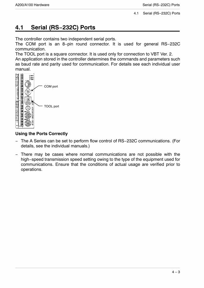
The controller contains two independent serial ports.The COM port is an 8−pin round connector. It is used for general RS−232Ccommunication.The TOOL port is a square connector. It is used only for connection to VBT Ver. 2.An application stored in the controller determines the commands and parameters suchas baud rate and parity used for communication. For details see each individual usermanual.
TOOL port
COM port
Using the Ports Correctly
− The A Series can be set to perform flow control of RS−232C communications. (Fordetails, see the individual manuals.)
− There may be cases where normal communications are not possible with thehigh−speed transmission speed setting owing to the type of the equipment used forcommunications. Ensure that the conditions of actual usage are verified prior tooperations.
A200/A100 HardwareSerial (RS−232C) Ports
4 − 4
4.1 Serial (RS−232C) Ports
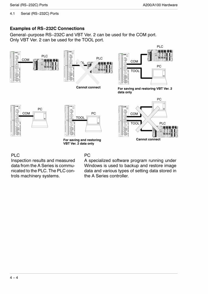
Examples of RS−232C ConnectionsGeneral−purpose RS−232C and VBT Ver. 2 can be used for the COM port.Only VBT Ver. 2 can be used for the TOOL port.
COMPLC
TOOLPLC
Cannot connect
TOOL
COM
PC
PLC
For saving and restoring VBT Ver. 2data only
PLCInspection results and measureddata from the A Series is commu-nicated to the PLC. The PLC con-trols machinery systems.
PCA specialized software program running underWindows is used to backup and restore imagedata and various types of setting data stored inthe A Series controller.
TOOL
COM
PC
PCCOM PC
TOOL
PLC
For saving and restoringVBT Ver. 2 data only
Cannot connect

Serial (RS−232C) PortsA200/A100 Hardware
4 − 5
4.2 COM port (Data output, VBT Ver. 2)
4.2 COM port (Data output, VBT Ver. 2)
Terminal PositionsA Hoshiden−manufactured connector (part no. TCS6180) is used as the COM(RS−232C) port on the controller unit.
Pin No. Wire color Signal Name
1 Red TxD
2 White RxD
3 Black RTS
4 Yellow CTS
5 Blue DSR
6 Green GND
7 Brown DCD
8 Gray DTR
Example wiring− IBM: Connection with an IBM PC−AT compatible
DCD
RxD
TxD
DTR
GND
DSR
RTS
CTS
RI
Pin Signal
Signal
TxD
RxD
RTS
CTS
DSR
GND
DCD
DTR
Pin
1
2
3
4
5
6
7
8
Imagechecker
PC−AT Compatible Machine
Cover CoverShield Shield
1
2
3
4
5
6
7
89
Please use the ANM81103 RS−232Ccable provided.(You do not need to prepare anything.)
[ANM81103]
PIN No.
Red TXDWhite RXDBlack RTSYellow CTSBlue DSRGreen GNDBrown DCDGray DTR
Wiring diagram is given above.
COM port Cable terminals
12345678
Wirecolor
SignalName
A SeriesImagechecker side
(to COM port)
PC side
ANM81103 serial cable(Length: approx. 3 m)
Controller−side terminal

A200/A100 HardwareSerial (RS−232C) Ports
4 − 6
4.2 COM port (Data output, VBT Ver. 2)
−Connection with PLCPlease make the connection using the ANM81303 RS232C cable (see below)according to the following wiring example.Since the wires on the PLC side of the RS232C cable are loose, please prepare themin accordance with the PLC you will be using. It may be necessary to make preparationsfor short circuits on PLCs; therefore, please make the connection after verifying thewiring example.
[ANM81303]
PIN No.
Red TXDWhite RXDBlack RTSYellow CTSBlue DSRGreen GNDBrown DCDGray DTR
COM port Cable terminals
12345678
Wirecolor
SignalName
A SeriesImagechecker side
(to COM port)
PC side
ANM81303 serial cable(Length: approx. 3 m)
Short
Short
Short
Short
Female
<MEW FP series>
ICHA series
MEW: FP series(Computer communication unit)
Pin
1
2
3
4
5
6
78
Cover
Red
White
Black
Yellow
Blue
Green
BrownGray
Wirecolor
–
Signal
TXD
RXD
RTS
CTS
DSR
GND
DCDDTR
Shield
Pin1
2
3
4
5
678
Cover
9
Signal
TXD
RXD
RTS
CTS
GNDDCD
DTR
Shield
FG
–
Inscription
Short
Short
<MEW FP series>ICHA series MEW: FP0Pin
1
2
3
4
5
6
78
Cover
Red
White
Black
Yellow
Blue
Green
BrownGray
Wirecolor
–
Signal
TXD
RXD
RTS
CTS
DSR
GND
DCDDTR
Shield
S
R
D
Signal
TXD
RXDGND

Serial (RS−232C) PortsA200/A100 Hardware
4 − 7
4.2 COM port (Data output, VBT Ver. 2)
Example of connection with Mitsubishi PLC
Example 1Mitsubishi A & Q series(9pins)
Example 2Mitsubishi A & Q series(25pins)
Pin123456789
Cover
SignalDCDRXDTXDDTRGNDDSRRTSCTS−
Shield
ICH A series
Pin12345678
Cover
WireRedWhiteBlackYellowBlueGreenBrownGray−
SignalTXDRXDRTSCTSDSRGNDDCDDTRShield
ICH A series
Pin12345678
Cover
WireRedWhiteBlackYellowBlueGreenBrownGray−
SignalTXDRXDRTSCTSDSRGNDDCDDTRShield
ICH A series
Pin12345678
Cover
WireRedWhiteBlackYellowBlueGreenBrownGray−
SignalTXDRXDRTSCTSDSRGNDDCDDTRShield
Pin1234567820Cover
SignalFGTXDRXDRTSCTSDSRGNDDCDDTRShield
Example 3Mitsubishi FX series(9pins)
Pin123456789
Cover
SignalDCDRXDTXDDSRGNDDTR−−−
Shield
Computer Link Communication with Mitsubishi A/Q series supports for “Type 4”.

A200/A100 HardwareSerial (RS−232C) Ports
4 − 8
4.2 COM port (Data output, VBT Ver. 2)
Example of connection with Omron PLC
Short Short
Short Short
Short
Short
ICHA series
ICHA series
Omron: C seriesEx. 1 (9 pin)
Omron: C seriesEx. 2: (25 pin)
Pin1
2
3
4
5
6
78
Cover
9
Signal
TXD
RXD
RTS
CTS
GNDShield
–
FG
–
–
Pin1
2
3
4
5
6
78
Cover
9
Signal
TXD
RXD
RTS
CTS
GND
Shield
–
FG
–
–
Pin
1
2
3
4
5
6
78
Cover
Red
White
Black
Yellow
Blue
Green
BrownGray
Wirecolor
–
Signal
TXD
RXD
RTS
CTS
DSR
GND
DCDDTR
Shield
Pin
1
2
3
4
5
6
78
Cover
Red
White
Black
Yellow
Blue
Green
BrownGray
Wirecolor
–
Signal
TXD
RXD
RTS
CTS
DSR
GND
DCDDTR
Shield

Serial (RS−232C) PortsA200/A100 Hardware
4 − 9
4.2 COM port (Data output, VBT Ver. 2)
Example of connection with Allen−Bradley PLC
Short
Short
ICH A seriesAllen−Bradley: SLC500
Pin1
2
3
4
5
6
78
Cover
9
Signal
RXD
TXD
DTR
GND
−Shield
DSR
DCD
RTS
CTS
Pin
1
2
3
4
5
6
78
Cover
Red
White
Black
Yellow
Blue
Green
BrownGray
Wirecolor
–
Signal
TXD
RXD
RTS
CTS
DSR
GND
DCDDTR
Shield

Controller−sideterminals
A200/A100 HardwareSerial (RS−232C) Ports
4 − 10
4.3 TOOL port (VBT Ver. 2 Port)
4.3 TOOL port (VBT Ver. 2 Port)
Terminal PositionsA Hoshiden−manufactured connector (part no. TCS7729) is used as the TOOL port onthe controller unit.
Pin No. Signal Name Pin No. Signal Name
1 Used 8 Used
2 Used 9 Used
3 TxD 10 CTS
4 Used 11 RxD
5 Used 12 Used
6 RTS 13 Used
7 GND Cover Shield
Using the TOOL Port CorrectlyThe highlighted signals are reserved. Do not use them.
Wiring Examples− Connection with an IBM PC−AT compatible
DCD
RxD
TxD
DTR
GND
DSR
RTS
CTS
RI
Pin
Cover
Signal
Shield
Signal
Reserved
TxD
RTS
GND
CTS
RxD
Shield
Pin
1
2
3
4
5
6
7
8
9
10
11
12
13
Cover
PC−AT Compatible MachineImagechecker
1
2
3
4
5
6
7
8
9
Connect as shown in the diagramon the left.
Reserved
Reserved
Reserved
Reserved
Reserved
Reserved
Reserved
Use the ANM812001 with an off−the−shelf cross cable.

Serial (RS−232C) PortsA200/A100 Hardware
4 − 11
4.3 TOOL port (VBT Ver. 2 Port)
9pinmale
9pinfemale
9pinfemale
ICHTOOLport ANM8121001 Commercially available
cross cable
Reserved
Reserved
Reserved
Reserved
Reserved
Reserved
Reserved
Matsushita ML connecter
Brown
Commercially availablecross cable
Pink
Green
Brown
Black
Purple
1
HoshidenTCP8951
ANM812001
23
56
87
910111213
D−Sub9pin male terminal
T×D
R×D
RTS
GND
CTS
Reserved
123456789
DCD
R×DT×D
DTR
GND
DSR
RTS
RI
CTS
D−Sub9pin female terminal D−Sub9pin female terminal123456789
DCDR×D
T×D
DTR
GND
DSR
RTS
CTS
RI
123456789
DCDR×D
T×D
DTR
GND
DSR
RTS
CTS
RI
Normally not used
1
2
8
9
12
5
134
4
123456789101112
1413
Red
White
Brown
Gray
Brown
Orange
Sky blue
Blue
Yellow
Br. green
Brown
Brown
GND
GND
GND
GND
AXM214001
GND

A200/A100 HardwareSerial (RS−232C) Ports
4 − 12
4.3 TOOL port (VBT Ver. 2 Port)

Chapter 5
About Camera Modes
5.1 Camera Modes 5 − 3. . . . . . . . . . . . . . . . . . . . . . . . . . . . . . . . .
5.2 Imaging Time for the Camera Modes(for memory image display) and Resolution 5 − 4. . . . . . . . .
5.3 Frame Mode and Field Mode 5 − 5. . . . . . . . . . . . . . . . . . . . .

A200/A100 HardwareAbout Camera Modes
5 − 2

About Camera ModesA200/A100 Hardware
5 − 3
5.1 Camera Modes
5.1 Camera Modes
Two of our cameras can be used with the A Series: The double−speed random camera,model ANM831, and the standard camera, model ANM832.The A Series supports a total of six camera modes. The camera mode is set accordingto whether the inspection object is moving or still, whether the illumination is continuousor strobe, and the camera type.Double−SpeedR d M d
This mode uses thed bl d d
Frame ModepRandom Modes double−speed random camera
ANM831. This mode is usedwhen the light is continuous andimaging objects are eithermoving or still.
Imaging time = (shutter time) + (16.7ms). Images areprocessed at the high resolution of 512 × 480 pixels.
This is the fastest mode for taking 512 × 480 pixel images.(maximum of 3 times faster than previous models)
The camera mode is switched Field ModeThe camera mode is switchedbetween frame and field bysetting items on a menu andchanging the settings of the DIPswitches on the back of thecamera. See note 1).
Fast imaging time = (shutter time) + (8.3ms). Images areprocessed at 512 × 240 pixel resolution.
This is the fastest imaging mode. (maximum of 4 timesfaster than previous models)
Normal Modes These modes use a normald l ANM832
Frame Modecamera, model ANM832.
This frame mode is used toimage moving objects usingstrobe light.
Either mode will support theimaging of still objects.
This mode can image still objects using continuous light orcan image moving objects using strobe light.
Imaging time = (33.3 to 49.9ms). Images are processed athigh resolution of 512 × 480 pixels.
When using strobe light, set this normal mode frame modeand switch the monitor display to Memory.
Field Mode
Imaging time = (16.7 to 33.3ms). Images are processed at512 × 240 pixels.
Internal Sync This mode uses NTSC signali t
Frame Modey ginput.
The field mode is used formoving images.The frame mode is used for still
The mode captures still images using an NTSC signal.
Imaging time = (shutter time) + (33.3 to 49.9ms). Imagesare processed at the high resolution of 512 × 480 pixels.
The frame mode is used for stillimages. Field Modeimages.
The A200 supports only cameraA in this mode.
The mode captures moving images using an NTSC signal.
Imaging time = (shutter time) + (16.7 to 33.3ms). Imagesare processed at a resolution of 512 × 240 pixels.
1) See the information about DIP switches on page 1−6.
A200/A100 HardwareAbout Camera Modes
5 − 4
5.2 Imaging Time for the Camera Modes (for memory image display) and Resolution
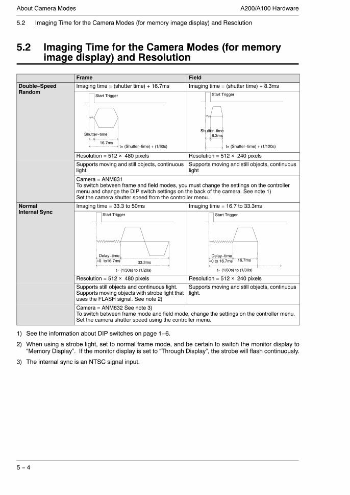
5.2 Imaging Time for the Camera Modes (for memoryimage display) and Resolution
Frame Field
Double−SpeedRa do
Imaging time = (shutter time) + 16.7ms Imaging time = (shutter time) + 8.3mspRandom
16.7ms
Shutter−time
t= (Shutter−time) + (1/60s)
Start Trigger
Shutter−time
t= (Shutter−time) + (1/120s)
Start Trigger
8.3ms
Resolution = 512 × 480 pixels Resolution = 512 × 240 pixels
Supports moving and still objects, continuouslight.
Supports moving and still objects, continuouslight
Camera = ANM831To switch between frame and field modes, you must change the settings on the controllermenu and change the DIP switch settings on the back of the camera. See note 1)Set the camera shutter speed from the controller menu.
NormalI te al S c
Imaging time = 33.3 to 50ms Imaging time = 16.7 to 33.3msInternal Sync
Delay−time=0 to16.7ms 33.3ms
t= (1/30s) to (1/20s)
Start Trigger
Delay−time=0 to 16.7ms 16.7ms
t= (1/60s) to (1/30s)
Start Trigger
Resolution = 512 × 480 pixels Resolution = 512 × 240 pixels
Supports still objects and continuous light.Supports moving objects with strobe light thatuses the FLASH signal. See note 2)
Supports moving and still objects, continuouslight.
Camera = ANM832 See note 3)To switch between frame mode and field mode, change the settings on the controller menu.Set the camera shutter speed using the controller menu.
1) See the information about DIP switches on page 1−6.
2) When using a strobe light, set to normal frame mode, and be certain to switch the monitor display to“Memory Display”. If the monitor display is set to “Through Display”, the strobe will flash continuously.
3) The internal sync is an NTSC signal input.

About Camera ModesA200/A100 Hardware
5 − 5
5.3 Frame Mode and Field Mode
5.3 Frame Mode and Field Mode
Frame ModeIn this mode, the camera captures an even number array and an odd number array andsends them to the image processing system. In the A Series, all 512 × 480 pixels aresent to memory and are then subject to image processing. Compared to field mode thisrequires more imaging time, but the resolution is higher.
Field ModeIn this mode, the camera captures either an even number array or an odd number arrayand sends it to the image processing system. In the A Series, 512 × 240 pixels arecaptured, but are transferred to memory as 512 × 480 pixels and then imageprocessed. Image capture is faster than in frame mode, but resolution is lower.
Frame capturememory image
Original image Field captureintermediate image
Field capturememory image
In the framemode, the originalimage is captured into 256 lev-el (8 bit) gray scale memory ata resolution of 512 × 480 pix-els.
In the field mode:1. Every other line (vertical) of the original camera
image is captured into 256 level (8 bit) gray scalememory at a resolution of 512 × 240 pixels.
2. The uncaptured lines are added during displayand image processing and the image iscaptured into a 256 level (8 bit) gray scalememory as a memory image, at a resolution of512 × 480 pixels.
Using Frame and Field Modes Correctly− Use memory image display for image display. Through Image Display takes an
excessively long time to complete image capture. In addition, there is a large amountof dispersion in the image capture timing (max.: 33ms) for Double−speed Randommodes.
− When connecting only one camera to the A200, connect it to Camera jack A.− When connecting two cameras to the A200, they must be the same camera type, use
the same mode, and have the same shutter speed.− Be sure to turn OFF the power when connecting a camera to the controller.− When using strobe light set the camera to normal field mode and be sure to switch
the monitor display to Memory Display. The strobe will flash continuously if themonitor display is set to Through Display.
− During field mode or when using a random camera the sensitivity decreases inproportion to increases in shutter speed. Smears may increase. When Throughimages are displayed the monitor display will have fluctuating brightness. (This is notan indication of a problem. The brightness will be stable in the memory images.)
− Be sure to use illumination that is designed for image processing.

A200/A100 HardwareAbout Camera Modes
5 − 6
5.3 Frame Mode and Field Mode

Chapter 6
Product Type Data Creation and Backup
6.1 Product Type Data Creation and Backup 6− 3. . . . . . . . . . .

A200/A100 HardwareOptional Memory
6 − 2

Optional MemoryA200/A100 Hardware
6 − 3
6.1 Product Type Data Creation and Backup
6.1 Product Type Data Creation and Backup
Product type data is created with the special−purpose keypad. You can back up thecreated product type data together with image data stored on the controller to a*Windows PC, then restore the data later.
KeypadThis is an operational keypad that can be used with any A Series product. Nearly allsettings can be made using this keypad.A 2m or 3m cable is provided.
Keypad
Vision Backup−Tool Version 2You can use this tool to store (back up) created product type data to a Windows PC*and then to transfer (restore) it to the controller.Even if created data was destroyed it can be quickly restored if has been backed up.Image data stored on the controller can also be stored on the Windows PC* in order tocontribute credibility to an inspection “failure.”If an inspected product is assembled into equipment and shipped, then it doesn’t workafter installation, the “failed” image can be matched with the product type data and sentby e−mail so the malfunction can be analyzed anywhere.
COM/TOOL
RS−232CCable
PC
Vision Backup−ToolVer2
* Dedicated software for personal computers running the Windows operating system(running on IBM PC−AT or compatible PC).Supported operating systemsWindows 95/Windows 98SE/Windows Me/Windows 2000/Windows XP(Ver. 2.0, 2.1: Windows 95/Windows 98/Windows Me/Windows 2000)
* Windows is a registered trademark of Microsoft Corporation in the United States andother countries.

A200/A100 HardwareOptional Memory
6 − 4
6.1 Product Type Data Creation and Backup

Chapter 7
General Specifications
7.1 Controller 7 − 3. . . . . . . . . . . . . . . . . . . . . . . . . . . . . . . . . . . . . .
7.2 Keypad 7 − 4. . . . . . . . . . . . . . . . . . . . . . . . . . . . . . . . . . . . . . . .
7.3 Monitor 7 − 5. . . . . . . . . . . . . . . . . . . . . . . . . . . . . . . . . . . . . . . .
7.4 Double−Speed Random Camera ANM831 7 − 6. . . . . . . . . .
7.5 CS−Mount Camera ANM832 7 − 7. . . . . . . . . . . . . . . . . . . . . .

A200/A100 HardwareGeneral Specifications
7 − 2

General SpecificationsA200/A100 Hardware
7 − 3
7.1 Controller
7.1 Controller
Item Specification
Processing resolution 512 × 480 pixels (horizontal × vertical)
Processing function Gray scale image/binarized image processing(details are determined by the application)
Settings Special−purpose keypad
External interface Serial COM port: RS−232CTOOL port: RS−232C
Parallel input Removable terminal block Input to 11 positions12 V to 24 V DC input Bidirectional photocoupler
Parallel output Removable terminal block output to 14 positions
NPNoutput type
12 V to 24 V DC photocoupler output (flash only 5 to 24V)
Photo−Mosoutput type
5 V to 24 V DC Photo−Mos relay output
Rated voltage 24 V DC
Allowable voltage range 21.6 to 26.4 V DC (including ripples)
Number ofconnected cameras
A100 Series 1 cameraconnected cameras
A200 Series Maximum 2 cameras
Rated current consumption 0.9A or less (when one camera is connected: 0.7A or less)
Operating ambient temperature 0 to 50_C (without icing and dew condensation)
Monitor output 1 ch: NTSC output
Storage ambient temperature – 20 to 60_C (without icing and dew condensation)
Operating / storage ambient humidity 35 to 75%RH (without icing and dew condensation at 25_C)
Noise resistance 1000 V pulse width 50ns/1µs(From a noise simulator. Note no keypad was connected)
Vibration resistance 10 to 55Hz, one vibration per minute, vibration width 0.75mm, 30 minuteseach in X, Y, Z directions
Shock resistance 196m/s2, five times each in X, Y, Z directions
Weight around 300g

A200/A100 HardwareGeneral Specifications
7 − 4
7.2 Keypad
7.2 Keypad
Item Specification
Operation bottuns, lever 8−direction lever, used jointly with the ENTER button: 1. A, B, C buttons =1 each
Operating / storage ambient humidity RH 35% to 75% (without icing and dew condensation at 25°C)Operating ambient temperature 0°C to +50°C (without icing and dew condensation)
Storage ambient temperature – 20°C to +60°C (without icing and dew condensation)
Weight Approx. 50g (excluding cable)

General SpecificationsA200/A100 Hardware
7 − 5
7.3 Monitor: ANMA810
7.3 Monitor: ANMA810
Item Specification
Rated voltage 100 V AC
Allowable voltage range 90 to 120 V AC
Rated power consumption 30 W or less
CRT 9 inch, White
Operation frequency Horizontal: 15.734 kHz Vertical: 59.94 Hz
Input level 1.0 Vp−p (Video signal: 0.7 Vp−p positive polaritySynchronization signal: negative polarity)
Input impedance 75Ω/High impedance, Bridge connection is available
Connector BNC connector
Vibration resistance 10 to 100 Hz one sweep per minuteamplitude 1 mm (10 to 22.3 Hz)acceleration 9.8 m/s2 (22.3 to 100 Hz)30 minutes each in X, Y and Z directions
Operating ambient temperature 0 to +40 °C (without icing and dew condensation)
Storage ambient temperature −20 to +60 °C (without icing and dew condensation)
Operating ambient humidity 35 to 75 % RH (without icing and dew condensation at 25°C)Storage ambient humidity 35 to 75 % RH (without icing and dew condensation at 25°C)Weight Approx. 6 kg

A200/A100 HardwareGeneral Specifications
7 − 6
7.4 Double−Speed Random Camera ANM831
7.4 Double−Speed Random Camera ANM831
Item Specification
Imaging element Readout of all pixels (interline transfer protocol)1/3 inch CCD fixed photo elements
Effective pixels Horizontal 659 pixels × vertical 494 pixels; pixel size = Square Pixel
Scanning method Non−interlaced mode (1/60s)2:1 interlaced (1/120s × 2)Switched mode (using DIP switches on camera back)
Shutter speed OFF (1/120), 1/200, 1/500, 1/1000, 1/2000, 1/4000, 1/8000, and 1/20000s(Set by the controller)
Gain switch and adjustment Gain switch = 0dB or gain up (DIP switch)Gain up volume is adjusted within the range of 0 to +10dB using the finetuning knob on the back of the camera.
Lens mount C mount
Rated voltage / Allowable voltagerange
12 V DC (supplied from the controller) /10.8 to 13.2 V DC
Rated current consumption 130mA
Operating ambient temperature Performance guarantee temperature = 0 to 40°C (without icing and dewcondensation)Operating = – 10 to 50°C (without icing and dew condensation)
Storage ambient temperature – 30 to 60°C (avoid ice and condensation)
Operating ambient humidity Performance guarantee ambient humidity = 50 to 70%RH (without icingand dew condensation at 25°C)Operating ambient humidity = 30 to 70%RH (without icing and dewcondensation at 25°C)
Storage ambient humidity 25 to 90%RH or less (without icing and dew condensation at 25°C)Vibration resistance 10 to 55 Hz, 1 vibration per minute, vibration width 1.2 mm, 30 minutes
each in X, Y, Z directions.
Shock resistance 700m/s2, three times each in X, Y and Z directions.
Weight around 70g (excluding cables, lens, and camera mounting hardware)

General SpecificationsA200/A100 Hardware
7 − 7
7.5 CS−Mount Camera ANM832
7.5 CS−Mount Camera ANM832
Item Specification
Imaging element Interline transmission method 1/3 inch CCD solid state imaging element
Effective pixels 768 pixels (horizontal) × 492 pixels (vertical)
Scanning method 2:1 interlace (1/60s)
Accumulation Frame accumulation
Shutter speed OFF 1/60s,Electronic shutter = 1/100, 1/125, 1/500, 1/1000, 1/2000, 1/4000, and1/10000s(Set by the controller)
Synchronization External synchronization
Lens mount CS mount
Rated voltage / Allowable voltagerange
12 V DC (supplied from the controller) /10.8 to 13.2 V DC
Rated current consumption 140mA
Operating ambient temperature 0°C to + 40°C (without icing and dew condensation)
Storage ambient temperature – 30°C to + 60°C (without icing and dew condensation)
Operating ambient humidity RH 35% to 85% (without icing and dew condensation at 25°C)Storage ambient humidity RH 85% or less (without icing and dew condensation at 25°C)Vibration resistance 10 to 55Hz, 1 vibration per minute, vibration width 1.2mm, 30 minutes
each in X, Y, Z directions.
Shock resistance 700m/s2, three times each in X, Y, Z directions
Weight Approx. 450g (excluding lens and holder)

A200/A100 HardwareGeneral Specifications
7 − 8
7.5 CS−Mount Camera ANM832

Chapter 8
Part Numbers
8.1 Controllers 8 − 3. . . . . . . . . . . . . . . . . . . . . . . . . . . . . . . . . . . . .
8.2 Cameras 8 − 5. . . . . . . . . . . . . . . . . . . . . . . . . . . . . . . . . . . . . . .
8.3 Double−Speed Random Camera Cable 8 − 6. . . . . . . . . . . .
8.4 Camera Extension Cable 8 − 7. . . . . . . . . . . . . . . . . . . . . . . . .
8.5 Keypad 8 − 8. . . . . . . . . . . . . . . . . . . . . . . . . . . . . . . . . . . . . . . .
8.6 Monitor 8 − 9. . . . . . . . . . . . . . . . . . . . . . . . . . . . . . . . . . . . . . . .
8.7 Data Backup Software and PC Cable 8 − 10. . . . . . . . . . . .
8.8 Lenses and Adapter Rings 8 − 11. . . . . . . . . . . . . . . . . . . . . .
8.9 Lighting for Image Processing 8 − 12. . . . . . . . . . . . . . . . . . .

A200/A100 HardwarePart Numbers
8 − 2

Part NumbersA200/A100 Hardware
8 − 3
8.1 Controllers
8.1 Controllers
Item Specification CE PartNumber
Micro−Imagechecker A200 series MulticheckerV2
NPN OutputInitial display : JapaneseIncludes Japanese manual
Conformed ANMA210V2
NPN OutputInitial display : EnglishIncludes English manual
Conformed ANMA212V2
Photo MOS OutputInitial display : EnglishIncludes English manual
Conformed ANMA218V2
Multichecker NPN OutputInitial display : JapaneseIncludes Japanese manual
Conformed ANMA210
NPN OutputInitial display : EnglishIncludes English manual
Conformed ANMA212
Photo MOS OutputInitial display : EnglishNo manual
Conformed ANMA213
OCV checker NPN OutputInitial display : JapaneseIncludes Japanese manual
Conformed ANMA220
NPN OutputInitial display : EnglishIncludes English manual
Conformed ANMA222
Photo MOS OutputInitial display : EnglishIncludes English manual
Conformed ANMA228
OCR Type NPN OutputInitial display : JapaneseIncludes Japanese manual
Conformed ANMA230
NPN OutputInitial display : EnglishIncludes English manual
Conformed ANMA232
Photo MOS OutputInitial display : EnglishIncludes English manual
Conformed ANMA238
Micro−Imagechecker A100 series MulticheckerV2
NPN OutputInitial display : JapaneseIncludes Japanese manual
Conformed ANMA110V2
NPN OutputInitial display : EnglishIncludes English manual
Conformed ANMA112V2
Photo MOS OutputInitial display : EnglishIncludes English manual
Conformed ANMA118V2
next page

A200/A100 HardwarePart Numbers
8 − 4
8.1 Controllers
Item Specification CE PartNumber
Micro−Imagechecker A100 series Multichecker NPN OutputInitial display : JapaneseIncludes Japanese manual
Conformed ANMA110
NPN OutputInitial display : EnglishIncludes English manual
Conformed ANMA112
Photo MOS OutputInitial display : EnglishNo manual
Conformed ANMA113
Spare Input/Output TerminalBlocks (for repairs)
Spare Input/Output Terminal Blocks (1 for input, 1for output)
N/A ANMA8001

Part NumbersA200/A100 Hardware
8 − 5
8.2 Cameras
8.2 Cameras
Item Specification CE Part Number
Double−speed random camera Double−speed random camera Conformed ANM831
CS−mount camera CS−mount camera Not conformed ANM832
ANM83203 *1)
Conformed ANM832CE
*1) Although ANM83203 is the same specification as ANM832, only the length of acable has a difference in both. Please refer to chapter 9.
The camera comes with adapter ring 1mm (2) and 0.5mm (1).

A200/A100 HardwarePart Numbers
8 − 6
8.3 Double−Speed Random Camera Cable
8.3 Double−Speed Random Camera Cable
Item Specification CE Part Number
ANM831 camera cable 3m Not conformed ANM84303
3m: CE compliant Conformed ANM84303CE
3m: Anti−bending camera cable Not conformed ANM84603
Use the camera extension cable when extending the double−speed random camera’scable 3 meters or more.
The length of a cable with CE is short a little.

Part NumbersA200/A100 Hardware
8 − 7
8.4 Camera Extension Cable
8.4 Camera Extension Cable
Item Specification CE Part Number
Extension cable forANM831/ANM832 (CE)
Extension cable = 2m: total 5m Not conformed ANM84002AANM831/ANM832 (CE)
Extension cable = 7m: total 10m Not conformed ANM84007A
Extension cable = 12m: total 15m Not conformed ANM84012A
Extension cable = 17m: total 20m Not conformed ANM84017A
Extension cable = 2m: total 5m: CE compliant Conformed ANM84002ACE
Extension cable = 7m: total 10m: CE compliant Conformed ANM84007ACE
Extension cable = 12m: total 15m: CE compliant Conformed ANM84012ACE
Extension cable = 17m: total 20: CE compliant Conformed ANM84017ACE
Anti−bending extension cable = 2m: total 5m Not conformed ANM84502
Anti−bending extension cable = 7m: total 10m Not conformed ANM84507
Anti−bending extension cable = 12m: total 15m Not conformed ANM84512
Anti−bending extension cable = 17m: total 20m Not conformed ANM84517
The length of a cable with CE is short a little.

A200/A100 HardwarePart Numbers
8 − 8
8.5 Keypad
8.5 Keypad
Item Specification CE Part Number
Keypad for A/M series Cable length = 2m Not conformed ANM85202
Cable length = 3m Not conformed ANM85203
Cable length = 5m Not conformed ANM85205
Cable length = 10m Not conformed ANM85210
Cable length = 2m: CE Conformed ANM85202CE
Cable length = 3m: CE Conformed ANM85203CE
Cable length = 5m: CE Conformed ANM85205CE
Cable length = 10m: CE Conformed ANM85210CE
The length of a cable with CE is short a little.

Part NumbersA200/A100 Hardware
8 − 9
8.6 Monitor
8.6 Monitor
Item Specification CE Part Number
Monitor Power code (length: 1.5m), Monitor cable (length: 3m)and BNC connector provided
Not conformed AMMA810
Monitor cable(PIN BNC)
Cable length: 3m N/A ANM87303(PIN−BNC)
Cable length: 5m ANM87305
Cable length: 10m ANM87310
Cable length: 15m ANM87315
Cable length: 20m ANM87320
BNC connector Connector that has a BNC terminal instead of a PINterminal
N/A ANM8606
Monitor and its related part are sold only in Japan.
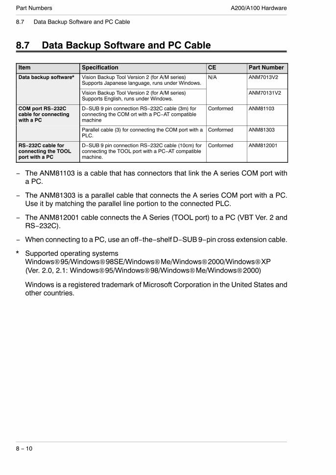
A200/A100 HardwarePart Numbers
8 − 10
8.7 Data Backup Software and PC Cable
8.7 Data Backup Software and PC Cable
Item Specification CE Part Number
Data backup software* Vision Backup Tool Version 2 (for A/M series)Supports Japanese language, runs under Windows.
N/A ANM7013V2
Vision Backup Tool Version 2 (for A/M series)Supports English, runs under Windows.
ANM70131V2
COM port RS−232Ccable for connectingwith a PC
D−SUB 9 pin connection RS−232C cable (3m) forconnecting the COM ort with a PC−AT compatiblemachine
Conformed ANM81103
Parallel cable (3) for connecting the COM port with aPLC.
Conformed ANM81303
RS−232C cable forconnecting the TOOLport with a PC
D−SUB 9 pin connection RS−232C cable (10cm) forconnecting the TOOL port with a PC−AT compatiblemachine.
Conformed ANM812001
− The ANM81103 is a cable that has connectors that link the A series COM port witha PC.
− The ANM81303 is a parallel cable that connects the A series COM port with a PC.Use it by matching the parallel line portion to the connected PLC.
− The ANM812001 cable connects the A Series (TOOL port) to a PC (VBT Ver. 2 andRS−232C).
− When connecting to a PC, use an off−the−shelf D−SUB9−pin cross extension cable.
* Supported operating systemsWindows 95/Windows 98SE/Windows Me/Windows 2000/Windows XP(Ver. 2.0, 2.1: Windows 95/Windows 98/Windows Me/Windows 2000)
Windows is a registered trademark of Microsoft Corporation in the United States andother countries.
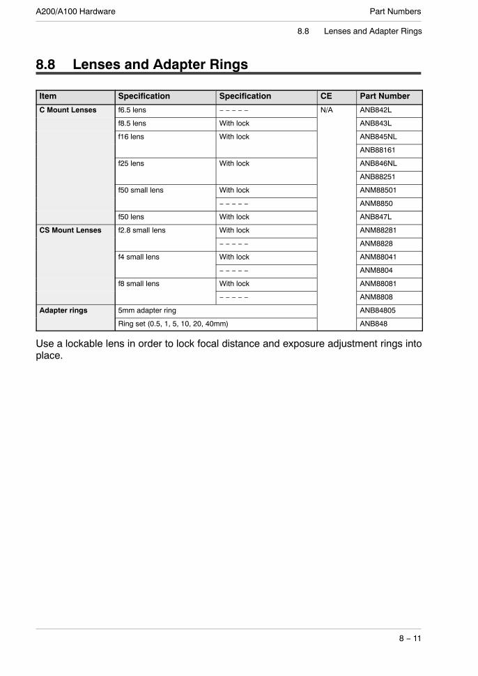
Part NumbersA200/A100 Hardware
8 − 11
8.8 Lenses and Adapter Rings
8.8 Lenses and Adapter Rings
Item Specification Specification CE Part Number
C Mount Lenses f6.5 lens − − − − − N/A ANB842L
f8.5 lens With lock ANB843L
f16 lens With lock ANB845NL
ANB88161
f25 lens With lock ANB846NL
ANB88251
f50 small lens With lock ANM88501
− − − − − ANM8850
f50 lens With lock ANB847L
CS Mount Lenses f2.8 small lens With lock ANM88281
− − − − − ANM8828
f4 small lens With lock ANM88041
− − − − − ANM8804
f8 small lens With lock ANM88081
− − − − − ANM8808
Adapter rings 5mm adapter ring ANB84805
Ring set (0.5, 1, 5, 10, 20, 40mm) ANB848
Use a lockable lens in order to lock focal distance and exposure adjustment rings intoplace.

A200/A100 HardwarePart Numbers
8 − 12
8.9 Lighting for Image Processing
8.9 Lighting for Image Processing
Item Specification Part NumberLED Ring light
[Di li h i ]outside diameter: Φ 50, red AULDR2−50RDg g
[Direct lighting] outside diameter: Φ 50, white AULDR2−50RD−SW
outside diameter: Φ 70, red AULDR2−70RD
outside diameter: Φ 70, red AULDR2−70RD−SW
Options for Ring light[Di li h i ]
For AULDR2−50RD/AULDR2 50RD SW
Polarizing plate AUPL−LDR−50Bp g g[Direct lighting]
/AULDR2−50RD−SW Diffusing plate AUDF−LDR−50B
Polarizing plate,diffusing plate,Installation adapter
AUAD−LDR−50B
For AULDR2−70RD/AULDR2 70RD SW
Polarizing plate AUPL−LDR−70A/AULDR2−70RD−SW Diffusing plate AUDF−LDR−70A
Bar light[Di li h i ]
light source size: 42 x 15, red AULDL−4215g[Direct lighting] light source size: 42 x 15, white AULDL−4215SW
Ring light[I di li h i ]
outside diameter: Φ 74 AULKR−70Ag g[Indirect lighting] outside diameter: Φ 102 AULFR−100
Back light[I di li h i ]
light source size: 27 x 27 AULDL−TP2727g[Indirect lighting] light source size: 43 x 35 AULDL−TP4335
light source size: 80 x 100 AULFL−100
Coaxial light[I di li h i ]
Coaxial light (26 x 28 translucent glass size) AULFV−34g[Indirect lighting] Coaxial light (32 x 36 translucent glass size) AULFV−50A
Power supply Digital light source (Output: 12V / 9.5W) AUPD−1012pp y
Digital modulated light source(Output: 12V/24V or 10 W)
ANB86001
Digital modulated light source(Output: 12V/24V or 30 W)
ANB86003
Cable Extension cable for 12V: 3m AUCB−3
Extension cable for 24V: 3m AUFCB−3
Light control cable (for ANB86001/ANB86003):3m
AUEXCB−B3
Inverter ringli h
Φ 60 ring light ANMF0064glight Φ 92 ring light ANMF0104
Replacement lamp: Φ 60 ring light ANMF0060
Replacement lamp: Φ 92 ring light ANMF0100
Halogen light 50W light source lamp housing ANMH105g gsource(100V AC)
100W light source lamp housing ANMH110(100V AC)
Replacement lamp for 50W light source lamp housing (ANMH105) ANMH305
Replacement lamp for 100W light source lamp housing (ANMH110) ANMH310
Fiber light guide Ring light guide ANMH200g g
Straight light guide ANMH210
2−branch light guide ANMH220
Flat light guide ANMH240
Adapter Light guide adapter (For connection of an ANMH240 to an ANMH110) ANMH800
* All lamps and its related part are sold in Japan.

Chapter 9
Dimension diagram
9.1 Controller 9 − 3. . . . . . . . . . . . . . . . . . . . . . . . . . . . . . . . . . . . . .
9.2 Camera 9 − 4. . . . . . . . . . . . . . . . . . . . . . . . . . . . . . . . . . . . . . . .
9.2.1 Double−Speed Random Camera ANM831 9 − 4. .
9.2.2 CS−Mount Camera ANM832 9 − 4. . . . . . . . . . . . . .
9.3 Camera Cable and Camera Extension Cable 9 − 5. . . . . . .
9.4 Keypad 9 − 6. . . . . . . . . . . . . . . . . . . . . . . . . . . . . . . . . . . . . . . .
9.5 Monitor: ANMA810 9 − 7. . . . . . . . . . . . . . . . . . . . . . . . . . . . . .
9.6 Lenses 9 − 8. . . . . . . . . . . . . . . . . . . . . . . . . . . . . . . . . . . . . . . .

A200/A100 HardwareDimension diagram
9 − 2

Dimension diagramA200/A100 Hardware
9 − 3
9.1 Controller
9.1 Controller
4−M3,depth1.5
(8)
(9.5)
104 (5.5)
55(5.5)
4074
120
(10)
*Onlyonecameracanattach
totheA100.Itdoes
nothavea
Cam
eraBport.
Unit:mm
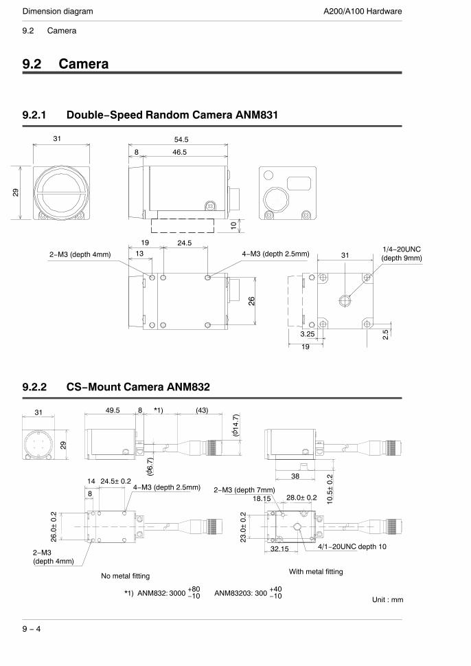
A200/A100 HardwareDimension diagram
9 − 4
9.2 Camera
9.2 Camera
9.2.1 Double−Speed Random Camera ANM831
1319 24.5
26
10
54.5
46.58
31
29
3.25
31
19
2−M3 (depth 4mm) 4−M3 (depth 2.5mm)1/4−20UNC(depth 9mm)
2.5
9.2.2 CS−Mount Camera ANM832
31
29
4-M3(深さ 2.5mm)
2-M3(深さ 4mm)
24.5±0.214
8
49.5
2-M3(深さ 7mm)
26
28
1/4-20UNC深さ10
23
18.15
38
10.5±0.2
32.15
8 3000+80−10 (43)
(
(φ6.7)
No metal fitting With metal fitting
28.0±0.2
23.0
±0.2
4/1−20UNC depth 10
18.15
32.15
2−M3 (depth 7mm)
2−M3(depth 4mm)
26.0
±0.2
24.5±0.2144−M3 (depth 2.5mm)
8
31
29
(6.7)
(14.7)
10.5
±0.238
849.5 *1) (43)
*1) ANM832: 3000 +80−10+40−10ANM83203: 300
Unit : mm

Dimension diagramA200/A100 Hardware
9 − 5
9.3 Camera Cable and Camera Extension Cable
9.3 Camera Cable and Camera Extension Cable
*B is the length of the installed cable.
The length of a cable withCE is short a little. Unit : mm

A200/A100 HardwareDimension diagram
9 − 6
9.4 Keypad
9.4 Keypad
A: Depends on the installed keypad.
54.4
The length of a cable with CE is short a little.
Unit : mm

Dimension diagramA200/A100 Hardware
9 − 7
9.5 Monitor: ANMA810
9.5 Monitor: ANMA810
(7)
215
(125)
220
160
280
Around 80mm ormore including thecable connection
Unit : mm
(68) 144.5
CAUTION LABEL
126
(20)
4−M3
(9)
NoteReserve at least 80mm of space to the rear of the monitor tofacilitate wiring and heat dissipation.Input/output to the monitor is with a BNC terminal.

A200/A100 HardwareDimension diagram
9 − 8
9.6 Lenses
9.6 Lenses
C mount lenses A B Filter size
ANB842L f=6.5 φ48 42 −
ANB843L f=8.5 φ42 40 M40.5
ANB845NL f=16 φ30 33 M27
ANB846NL f=25 φ30 37.3 M27
ANB88161 f=16 φ30.5 25 M25.5
ANB88251 f=25 φ30.5 25.5 M25.5
ANB847L f=50 φ48 48 M46
ANM8850 f=50 φ27.5 38.5 M25.5
ANM88501 f=50 φ30.5 38.5 M25.5
CS mount lenses A B Filter size
ANM8808 f=8 φ34 35 M30.5
ANM88081 f=8 φ31 35 M25.5
ANM8804 f=4 φ34 41 M30.5
ANM88041 f=4 φ31 40 M25.5
ANM8828 f=2.8 φ34 38 M30.5
ANM88281 f=2.8 φ31 37.5 M25.5
B
Locking screws (only on lenses with lock)
A

Dimension diagramA200/A100 Hardware
9 − 9
9.6 Lenses
DimensionsANM8850
38.5 4
M25.5×0.5
φ27.5
φ29
1:2.850mmφ25.5
1−32 UNF CS−MOUNT
φ29
ANM8850138.5 4
19.3
M25.5×0.5
7
φ30.5
φ29
φ27.5
5.35
5.75
1−32 UNF CS−MOUNT
ANM8808
38
TVLE
NSF1.28m
m
JAPA
N
M30.5×0.5
φ34
1−32 UNF CS−MOUNT
φ35
35
CO
4

A200/A100 HardwareDimension diagram
9 − 10
9.6 Lenses
ANM88081
M25.5×0.5
35
φ31
near
JAPA
N
φ27
φ31
1−32 UNF CS−MOUNT
4.5
20
11.5
4.5
ANM8804
38
M30.5×0.5
φ34
41 4
1−32 UNF CS−MOUNT
φ35
TVLE
NSF1.24m
m
JAPA
N CO
ANM88041
40 4.5
M25.5×0.5
20
11.5
φ31
φ27
φ31
4.5
near
JAPA
N
1−32 UNF CS−MOUNT

Dimension diagramA200/A100 Hardware
9 − 11
9.6 Lenses
ANM8828
38
38 4
1−32 UNF CS−MOUNT
φ35
φ34
TVLE
NSF1.42.8m
m
JAPA
N
CO
ANM88281
37.5 4.2
20
near
JAPA
N
φ31
1−32 UNF CS−MOUNT
φ31
11.5
4.5

A200/A100 HardwareDimension diagram
9 − 12
9.6 Lenses

Chapter 10
Pin Assignment
10.1 Camera Pin Positions (ANM831) 10− 3. . . . . . . . . . . . . . . . .
10.2 Camera Pin Positions (ANM832) 10− 4. . . . . . . . . . . . . . . . .

A200/A100 HardwarePin Assignment
10 − 2

Pin AssignmentA200/A100 Hardware
10 − 3
10.1 Camera Pin Positions (ANM831)
10.1 Camera Pin Positions (ANM831)
1
23
4
5
6
78
910
11
12
No.123456
Signal NamePOWER GND
+12VVideo shieldVIDEO
HD shieldHD
No.789101112
Signal NameSHT3SHT1SHT2
SHT GNDTRIGGERVD shield
View direction View direction
HR10A−10P−12P(Hirose)
HR10A−10P−12S(Hirose)
Micro−Imagechecker
CAMERA−A
Female Male
1 12 2
3 3
4 45 56 6
7 7
8 8
9 9
10 10
11 1112 12
AUX
Female Male
No.214365712891110
Signal Name+12V
POWER GNDVIDEO
Video shieldHD
HD shieldSHT3GNDSHT1SHT2
TRIGGERSHT GND
214365712891110
Signal Name+12V
POWER GNDVIDEO
Video shieldHD
HD shieldSHT3GNDSHT1SHT2
TRIGGERSHT GND
Camera ANM831
ANM843**
No.
HR10A−10R−12S(Hirose)
HR10A−10R−12P(Hirose)
34
5
68
9
1
2
1011
12
7
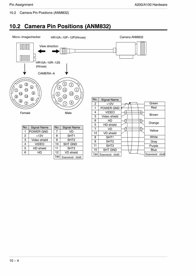
A200/A100 HardwarePin Assignment
10 − 4
10.2 Camera Pin Positions (ANM832)
10.2 Camera Pin Positions (ANM832)
No.123456
Signal NamePOWER GND
+12VVideo shieldVIDEO
HD shieldHD
No.789101112
Signal NameVDSHT1SHT2
SHT GNDSHT3
VD shield
View direction
HR10A−10P−12P(Hirose)Micro−Imagechecker
CAMERA−A
Female Male
214365712891110
Signal Name+12V
POWER GNDVIDEO
Video shieldHD
HD shieldVD
VD shieldSHT1SHT2SHT3
SHT GND
GreenRed
Brown
Orange
BluePurpleGrayWhite
Yellow
Camera ANM832
No.
HR10A−10R−12S(Hirose)
1
23
4
5
6
78
910
11
12
34
5
68
9
1
2
1011
12
7

Chapter 11
Manual revision history
11.1 Manual revision history 11− 3. . . . . . . . . . . . . . . . . . . . . . . . .

A200/A100 HardwareManual revision history
11 − 2

Manual revision historyA200/A100 Hardware
11 − 3
11.1 Manual revision history
11.1 Manual revision history
Manual No. Issue date Description of changes
Sep. 1999 First edition
ARCT1F317E Aug. 2000 Corrections associated with upgrade to Ver. 1.2 of the A200/A100g Corrections associated with upgrade to Ver. 1.2 of the A200/A100MultiChecker.
Sep. 2000 Printed and bound edition: Corrections added
ARCT1F317E−1 Oct. 2000 Corrections added
ARCT1F326E Jul. 2001 Added content−A200 series OCV checker−LED for image processing−COM port and example of connection to PLC−Multichecker V2 part number−Part number change of camera extention cable.Addition of OS compatible with VBT Ver. 2.
ARCT1F326E−1 Oct. 2001 Printed and bound editionAdded content−Lens f=16, f=25−Camera ANM832
ARCT1F326E−2 Jun. 2002 GENERAL INSTRUCTIONS“Before Creating Type Data” corrected
Chapter 2 Page 9 and 10“View range and Lens Selection Tables” corrected
ARCT1F326E−3 Jan. 2003 4th edition
ARCT1F326E−4 Feb. 2004 Changed : Monitor
−AUGPBM910 to ANMA810
ARCT1F326E−5 Oct. 2005 Added content−Anti−bending camera cables−Filter size for lens
ARCT1F425E Aug. 2006 First edition
−Revision associated with a change of the brand (NAiS toPanasonic).
−Corrections of errors in writing.
−Addition of descriptions about grounding.

A200/A100 HardwareManual revision history
11 − 4