all techniques - in brief
TRANSCRIPT

8/6/2019 All Techniques - In Brief
http://slidepdf.com/reader/full/all-techniques-in-brief 1/87
1
Ultrasonic C-Scan VideoCorrosion Mapping

8/6/2019 All Techniques - In Brief
http://slidepdf.com/reader/full/all-techniques-in-brief 2/87
2
Corrosion Mapping
Principles of Video Corrosion Mapping
Real time colour graphic images of corrosion or
erosion are produced by use of a standard 0°transducer. By using a CCD camera and the video-
tracking system, real time graphic images are
generated by scanning a hand held probe.
A Light Emitting Diode (LED) is attached to the
transducer. The camera tracks this LED to obtain
the positional information required by the system.
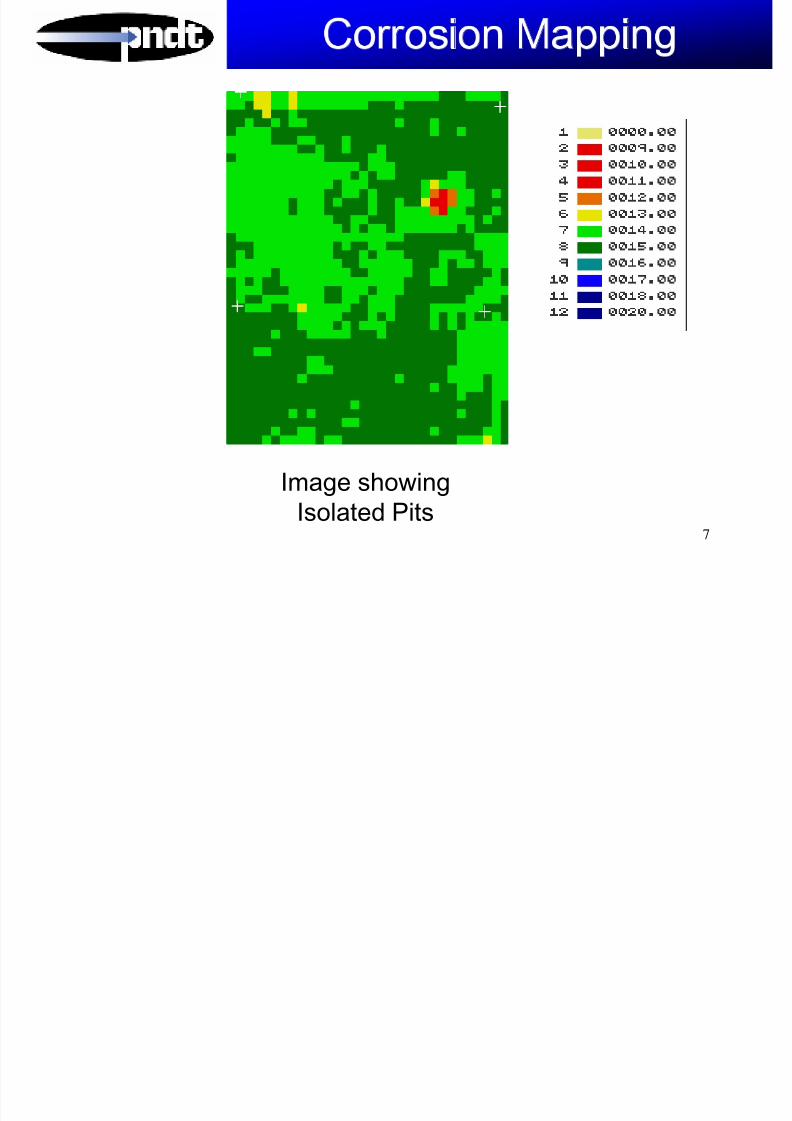
Each thickness is assigned a separate colour, and agraphic contoured image is produced showing a
topographical map of the internal surface condition.

8/6/2019 All Techniques - In Brief
http://slidepdf.com/reader/full/all-techniques-in-brief 3/87
3
Corrosion Mapping
CCD Camera
Microplus Imaging System
Light Emitting Diode

8/6/2019 All Techniques - In Brief
http://slidepdf.com/reader/full/all-techniques-in-brief 4/87
4
A selection of software routines such as 3-Denhancements, material percentage losses, cross-
sectional images, is included in the µmapsoftware package

8/6/2019 All Techniques - In Brief
http://slidepdf.com/reader/full/all-techniques-in-brief 5/87
5
Corrosion Mapping
Composite Image
By Joining Scan
Files

8/6/2019 All Techniques - In Brief
http://slidepdf.com/reader/full/all-techniques-in-brief 6/87
6
Corrosion Mapping
Key Features
As no mechanical scanners are necessary, thistechnique permits the ultrasonicimaging of complex geometry’s such as
Tees, Valves and Bends.
Colour composite images may be generatedby joining individual scan areas, to show theoverall condition of plant.
Coverage is guaranteed as non-inspected
areas are highlighted On-Line analysis
Automatic Report generation
8/6/2019 All Techniques - In Brief
http://slidepdf.com/reader/full/all-techniques-in-brief 7/87
7
Corrosion Mapping
Image showing
Isolated Pits

8/6/2019 All Techniques - In Brief
http://slidepdf.com/reader/full/all-techniques-in-brief 8/87
8
Time of Flight Diffraction
TOFD

8/6/2019 All Techniques - In Brief
http://slidepdf.com/reader/full/all-techniques-in-brief 9/87
9
Developed to accurately size and monitor the
through wall height of in service flaws in the nuclear
industry.
Equally effective for the detection of flaws in welding,
irrespective of type or orientation.
Does not rely on the reflectivity of the flaw
Uses the diffracted sound initiated from the flaw tips

8/6/2019 All Techniques - In Brief
http://slidepdf.com/reader/full/all-techniques-in-brief 10/87
10
2 Probes opposite
each other. 1 transmittingand 1 receiving the signals

8/6/2019 All Techniques - In Brief
http://slidepdf.com/reader/full/all-techniques-in-brief 11/87
11
Tx Rx
Lateral wave
Signal returned from backwall
Energy is transmitted in to the Material in short burstsThe energy spreads out into an angular beam

8/6/2019 All Techniques - In Brief
http://slidepdf.com/reader/full/all-techniques-in-brief 12/87
12
Planar flaw
upper tip
lower tip
Tx Rx
Lateral wave
Backwall
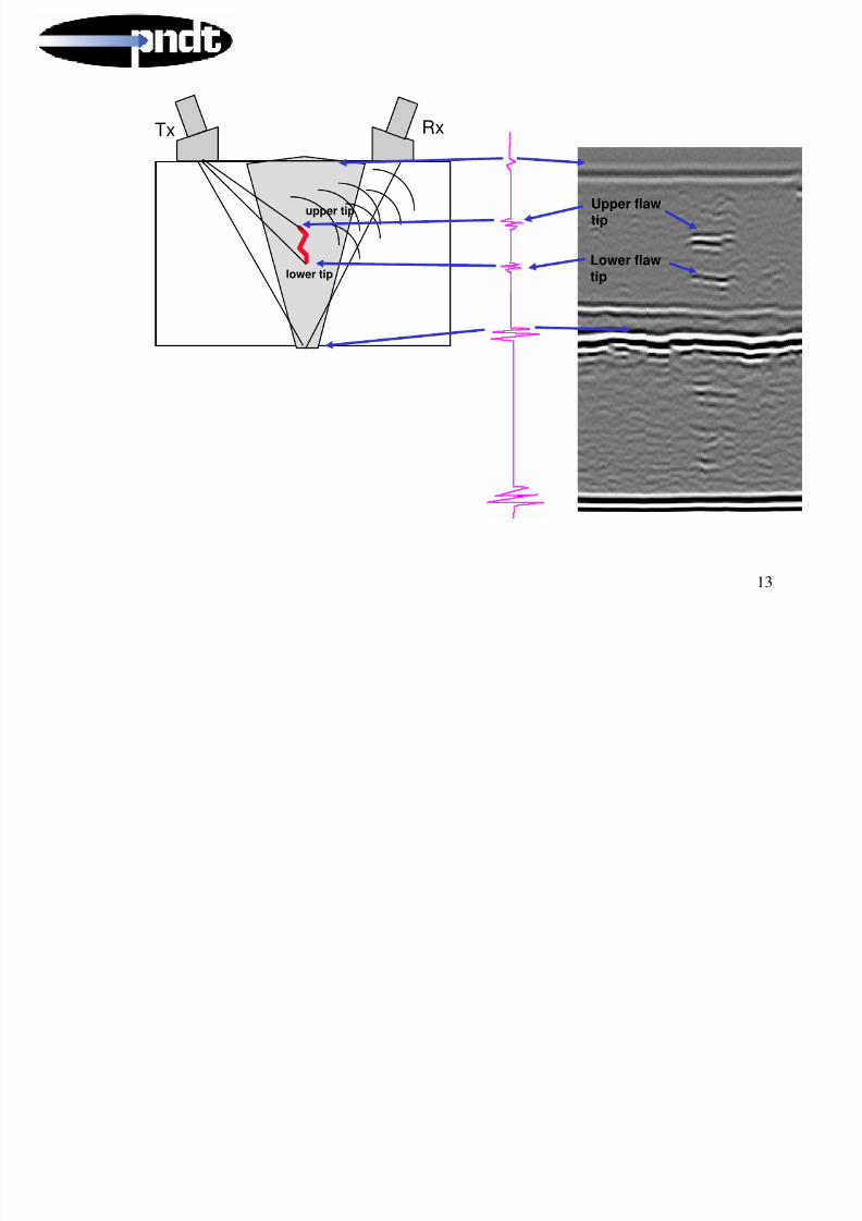
Energy is diffracted from both upper and lower flaw tips
8/6/2019 All Techniques - In Brief
http://slidepdf.com/reader/full/all-techniques-in-brief 13/87
13
upper tip
lower tip
Tx Rx
Upper flaw
tip
Lower flawtip

8/6/2019 All Techniques - In Brief
http://slidepdf.com/reader/full/all-techniques-in-brief 14/87
14
Benefits of TOFD Real Rime Inspection Results
Superior inspection reliability
Reduced inspection time
Accurate sizing
Reliable propagation monitoring
No necessity to shut down plant asinspection can be deployed "on-line"
Cost effective
Hard Copy Evidence
Repeatable
Easy Storage of data

8/6/2019 All Techniques - In Brief
http://slidepdf.com/reader/full/all-techniques-in-brief 15/87
15
Corrosion
Top Surface
Inner Surface
TOFD forWeld root Corrosion

8/6/2019 All Techniques - In Brief
http://slidepdf.com/reader/full/all-techniques-in-brief 16/87
16

8/6/2019 All Techniques - In Brief
http://slidepdf.com/reader/full/all-techniques-in-brief 17/87
17

8/6/2019 All Techniques - In Brief
http://slidepdf.com/reader/full/all-techniques-in-brief 18/87
18

8/6/2019 All Techniques - In Brief
http://slidepdf.com/reader/full/all-techniques-in-brief 19/87
19
Phased ArrayPhased Array – –
A Basic IntroductionA Basic Introduction

8/6/2019 All Techniques - In Brief
http://slidepdf.com/reader/full/all-techniques-in-brief 20/87
20
Why Phased Array?
• High speed electronic scanning without moving parts
• Improved inspection capabilities through softwarecontrol of beam characteristics
• Inspection with multiple angles with single,
electronically controlled probe
• Greater flexibility for inspection of complex
geometries
– Optimized focusing
– Optimized beam angle

8/6/2019 All Techniques - In Brief
http://slidepdf.com/reader/full/all-techniques-in-brief 21/87
21
Phased-Array
ProbeBasically, a phased-array is a long conventional probe
cut into many elements.

8/6/2019 All Techniques - In Brief
http://slidepdf.com/reader/full/all-techniques-in-brief 22/87
22
Electronic (Linear)Scanning

8/6/2019 All Techniques - In Brief
http://slidepdf.com/reader/full/all-techniques-in-brief 23/87
23
8/6/2019 All Techniques - In Brief
http://slidepdf.com/reader/full/all-techniques-in-brief 24/87
24
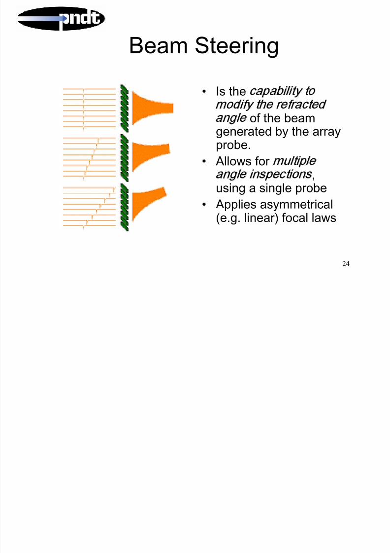
Beam Steering
• Is the capability to
modify the refracted
angle of the beamgenerated by the array
probe.• Allows for multiple
angle inspections,using a single probe
• Applies asymmetrical(e.g. linear) focal laws

8/6/2019 All Techniques - In Brief
http://slidepdf.com/reader/full/all-techniques-in-brief 25/87
25

8/6/2019 All Techniques - In Brief
http://slidepdf.com/reader/full/all-techniques-in-brief 26/87
26
Combined Beam
Processing
Linear combined with steering and focusing

8/6/2019 All Techniques - In Brief
http://slidepdf.com/reader/full/all-techniques-in-brief 27/87
27
Applications ApplicationsInIn--service weld inspection including Stressservice weld inspection including Stress
Corrosion CrackingCorrosion Cracking
As welded defect detection As welded defect detection
Complex GeometriesComplex Geometries – – Nozzles, FlangesNozzles, Flanges, Shafts, Shafts
CC--Scan mappingScan mapping

8/6/2019 All Techniques - In Brief
http://slidepdf.com/reader/full/all-techniques-in-brief 28/87
28

8/6/2019 All Techniques - In Brief
http://slidepdf.com/reader/full/all-techniques-in-brief 29/87
29
CHIME
8/6/2019 All Techniques - In Brief
http://slidepdf.com/reader/full/all-techniques-in-brief 30/87
30
CHIME
Creeping Head-
Wave Inspection
Method
CHIME

8/6/2019 All Techniques - In Brief
http://slidepdf.com/reader/full/all-techniques-in-brief 31/87
31
CHIME
An ultrasonic technique for the efficient, rapid and
complete inspection of pipe or plate called CHIME for
the examination of under-clamp or under-support
corrosion:
Large area, single pass corrosion,
pitting and crack detection
Probe separation up to 1m or more 100% coverage of material between the
probes
Suitable for steel pipes and plate
Sensitive to both internal and external
surfaces
Applications of CHIME

8/6/2019 All Techniques - In Brief
http://slidepdf.com/reader/full/all-techniques-in-brief 32/87
32
Applications of CHIME
• Pipe Supports, saddles or
sleepers
• Clamps
• Vessels/Tanks
• Pipe screening for internalcorrosion
• Pipes with limited access
The CHIME technique

8/6/2019 All Techniques - In Brief
http://slidepdf.com/reader/full/all-techniques-in-brief 33/87
33
The CHIME technique
Time
Head WavesBulk Waves
CHIME on Isolated Pits

8/6/2019 All Techniques - In Brief
http://slidepdf.com/reader/full/all-techniques-in-brief 34/87
34
CHIME on Isolated Pits
P1 P2 P3
e Probe movement Tim
Pit depth is 25% to 100% of WT
25% 100% 55%
CHIME for Internal Pipe Inspection

8/6/2019 All Techniques - In Brief
http://slidepdf.com/reader/full/all-techniques-in-brief 35/87
35
CHIME for Internal Pipe Inspection
CHIME for Pipe Supports

8/6/2019 All Techniques - In Brief
http://slidepdf.com/reader/full/all-techniques-in-brief 36/87
36
CHIME for Pipe Supports
Example of data collection around a pipe support
Note: Inspection can be carried out using either set up a) or b) only
CHIME on 6” Pipe Section

8/6/2019 All Techniques - In Brief
http://slidepdf.com/reader/full/all-techniques-in-brief 37/87
37
p
Wavemaker

8/6/2019 All Techniques - In Brief
http://slidepdf.com/reader/full/all-techniques-in-brief 38/87
38
Wavemaker
Pipe Screening System

8/6/2019 All Techniques - In Brief
http://slidepdf.com/reader/full/all-techniques-in-brief 39/87
39
Waves are sent along the pipe• 10’s of meters of
pipe areexamined fromone location
• Difficult toinspect areas,such as roadways
can be screenedfor defects

8/6/2019 All Techniques - In Brief
http://slidepdf.com/reader/full/all-techniques-in-brief 40/87
40
Capabilities
• Can be performed at elevated temperatureswithout taking the pipe out of service
• 100% of the pipe is inspected (within thediagnostic length of a test)
• Pulse echo type operation provides informationon feature position and approximate size
• Sophisticated analysis aids interpretation of results

8/6/2019 All Techniques - In Brief
http://slidepdf.com/reader/full/all-techniques-in-brief 41/87
41
Target Applications
• Rapid, full coverage screening of pipes
• Especially cost effective in difficult to access
locations – Sleeved road crossings
– Corrosion under insulation
– Wall penetrations – Pipe racks
– Rope access
• Can detect cracks and general metal loss (greaterthan 5% of the cross-sectional area)

8/6/2019 All Techniques - In Brief
http://slidepdf.com/reader/full/all-techniques-in-brief 42/87
42
Limitations
• Highly attenuous bitumas based coatings
and denso wraps.
• Internal concrete lining on pipes
• Pipe with a high level of general corrosion
will reduce the effective scanning lengths.
• Heavy clay soils.
• Short, less than 5mtr, length of piping.

8/6/2019 All Techniques - In Brief
http://slidepdf.com/reader/full/all-techniques-in-brief 43/87
43
Pre-inspection Set-up
• A ring of
transducers isplaced around thepipe
• No couplant isrequired
• Usually no surface
preparationrequired

8/6/2019 All Techniques - In Brief
http://slidepdf.com/reader/full/all-techniques-in-brief 44/87
44
Small Diameter Pipes
• Tested using solidrings
• For pipes 1 - 8inches diameter
• Can be mounted inless than a minute
• 3 inches clearance
needed aroundpipe8” Ring R2F8

8/6/2019 All Techniques - In Brief
http://slidepdf.com/reader/full/all-techniques-in-brief 45/87
45
Large Diameter Pipes• Tested using inflatable
ring• For pipes 6 inches orgreater
• Employ conventionalfoot pump to inflate
• 2 inches clearance
needed around mostof pipe
12” Ring R2B12
8/6/2019 All Techniques - In Brief
http://slidepdf.com/reader/full/all-techniques-in-brief 46/87
46
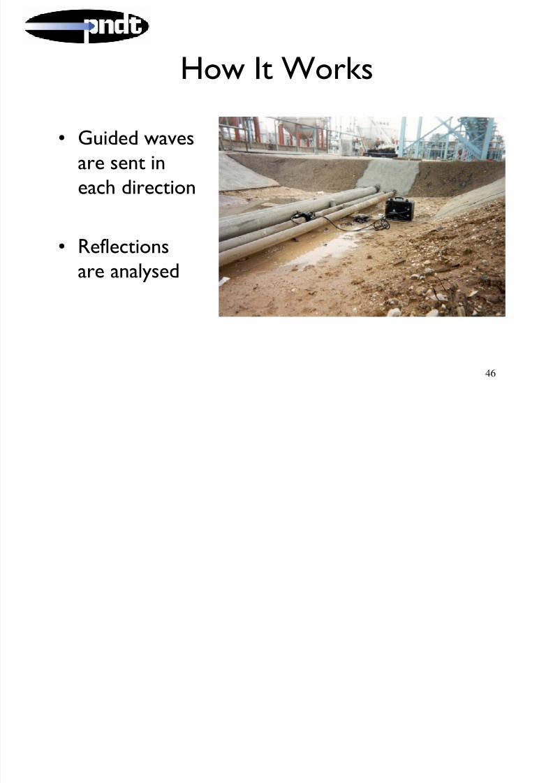
How It Works
• Guided wavesare sent ineach direction
• Reflectionsare analysed

8/6/2019 All Techniques - In Brief
http://slidepdf.com/reader/full/all-techniques-in-brief 47/87
47
Position of Ring
Decay CurvesCorrosion is indicated
by large red component
Iconic representation
of identified features
ForwardBackward
Series of Welds
Example #1

8/6/2019 All Techniques - In Brief
http://slidepdf.com/reader/full/all-techniques-in-brief 48/87
48
Pipes passing through earth wall

8/6/2019 All Techniques - In Brief
http://slidepdf.com/reader/full/all-techniques-in-brief 49/87
49
Corrosion at entrance to sleevedroad crossing
-30.0 -20.0 -10.0 0.0 10.00.0
0.2
0.4
0.6
0.8
1.0
Distance (m)
A m p ( m V )
+F1 +F2 +F3+F4-F1-F2-F3-F4
Corrosion
Example #2

8/6/2019 All Techniques - In Brief
http://slidepdf.com/reader/full/all-techniques-in-brief 50/87
50
Example #2
Pipes passing through concrete wall
8 inch pipeunder test
10 inch pipeunder test

8/6/2019 All Techniques - In Brief
http://slidepdf.com/reader/full/all-techniques-in-brief 51/87
51
Result from (corroded) 10 inch pipe
-20.0 -10.0 0.0 10.0 20.00.0
0.5
1.0
1.5
2.0
Distance (m)
A m p ( m V )
-F
Typical Ranges

8/6/2019 All Techniques - In Brief
http://slidepdf.com/reader/full/all-techniques-in-brief 52/87
52
(in each direction, using standard transducers)
• Ideal conditions 80m + (best recorded 220m)
• Typical 30 year old pipe with little internal or externalcorrosion 40m
• Typical 30 year old pipe with some general corrosion20m
• Typical pipe wrapped in factory applied foam 15m
• Heavily corroded pipe or pipe that is bitumenwrapped 5m
• Six welds
• The first flange or the second bend or branch
Note: these ranges can be doubled by using newly available low frequency
transducers although a reduction in sensitivity is also present

8/6/2019 All Techniques - In Brief
http://slidepdf.com/reader/full/all-techniques-in-brief 53/87
53
How to Most Effectively Use the System
• Best used as a screening tool that is part of a
more comprehensive testing strategy – Good at quickly determining which out of a series of
road crossings is most heavily corroded
– Good at quickly locating areas of probable concern
– Can not determine exact sizes (only a roughclassification can be given)

8/6/2019 All Techniques - In Brief
http://slidepdf.com/reader/full/all-techniques-in-brief 54/87
54
INCOTESTINsulated COmponent TEST
INCOTEST I t d ti

8/6/2019 All Techniques - In Brief
http://slidepdf.com/reader/full/all-techniques-in-brief 55/87
55
INCOTEST - Introduction• INCOTEST (INnsulated
COmponent TEST)
• Pulsed Eddy Current - ThicknessMeasurement Through insulation
• Average Thickness over aFootprint
• On-Stream No InsulationRemoval
• Detects Both Internal and
External Wall Loss
INCOTEST
8/6/2019 All Techniques - In Brief
http://slidepdf.com/reader/full/all-techniques-in-brief 56/87
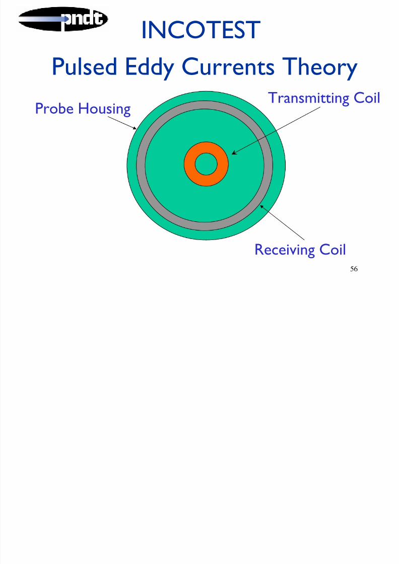
56
Pulsed Eddy Currents Theory
Probe Housing
Receiving Coil
Transmitting Coil
INCOTEST

8/6/2019 All Techniques - In Brief
http://slidepdf.com/reader/full/all-techniques-in-brief 57/87
57
Theory summary• Pulsed Magnetic Field
• Eddy Currents are induced
• Measurement of Eddy Current Voltage
• Detect start / finish of eddy currents in material
• Eddy current Duration / Thickness relationship
INCOTEST

8/6/2019 All Techniques - In Brief
http://slidepdf.com/reader/full/all-techniques-in-brief 58/87
58
Area of Measurement
Volumetric reading over
a given area (footprint)
INCOTEST

8/6/2019 All Techniques - In Brief
http://slidepdf.com/reader/full/all-techniques-in-brief 59/87
59
Area of Measurement
Reading taken overan area of 100% volume of material
INCOTEST

8/6/2019 All Techniques - In Brief
http://slidepdf.com/reader/full/all-techniques-in-brief 60/87
60
Reading taken over corroded area.
Reading will be the remaining volume of material as compared to the reference reading
Area of Measurement
INCOTEST Restrictions

8/6/2019 All Techniques - In Brief
http://slidepdf.com/reader/full/all-techniques-in-brief 61/87
61
INCOTEST - Restrictions• Only suitable for low alloy steels.
• Does not detect isolated pits. Measure the average wall
thickness over a footprint.
• Repeatability typically +/- 2%.
• Limited to wall thickness up to 65mm.
• Limited to insulated pipe diameters over 50mm.
• Cannot differentiate OD from ID loss.

8/6/2019 All Techniques - In Brief
http://slidepdf.com/reader/full/all-techniques-in-brief 62/87
62
• Can work up to 5hrs
on one battery pack.
• Probes can be up to200mtr away from
base unit.

8/6/2019 All Techniques - In Brief
http://slidepdf.com/reader/full/all-techniques-in-brief 63/87
63
• Measures throughany non-magnetic
material, e.g.insulation, concrete,
fire retarder,refractory cement,water, timber and air
8/6/2019 All Techniques - In Brief
http://slidepdf.com/reader/full/all-techniques-in-brief 64/87
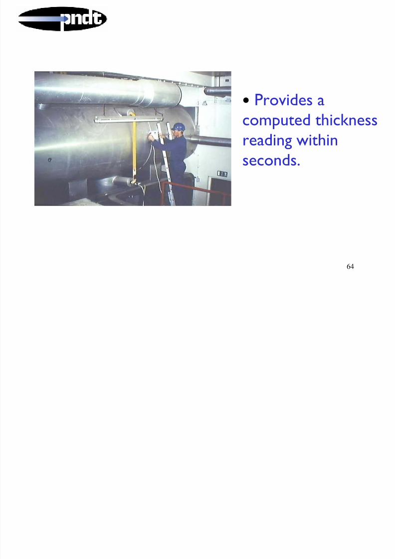
64
• Provides acomputed thickness
reading within
seconds.
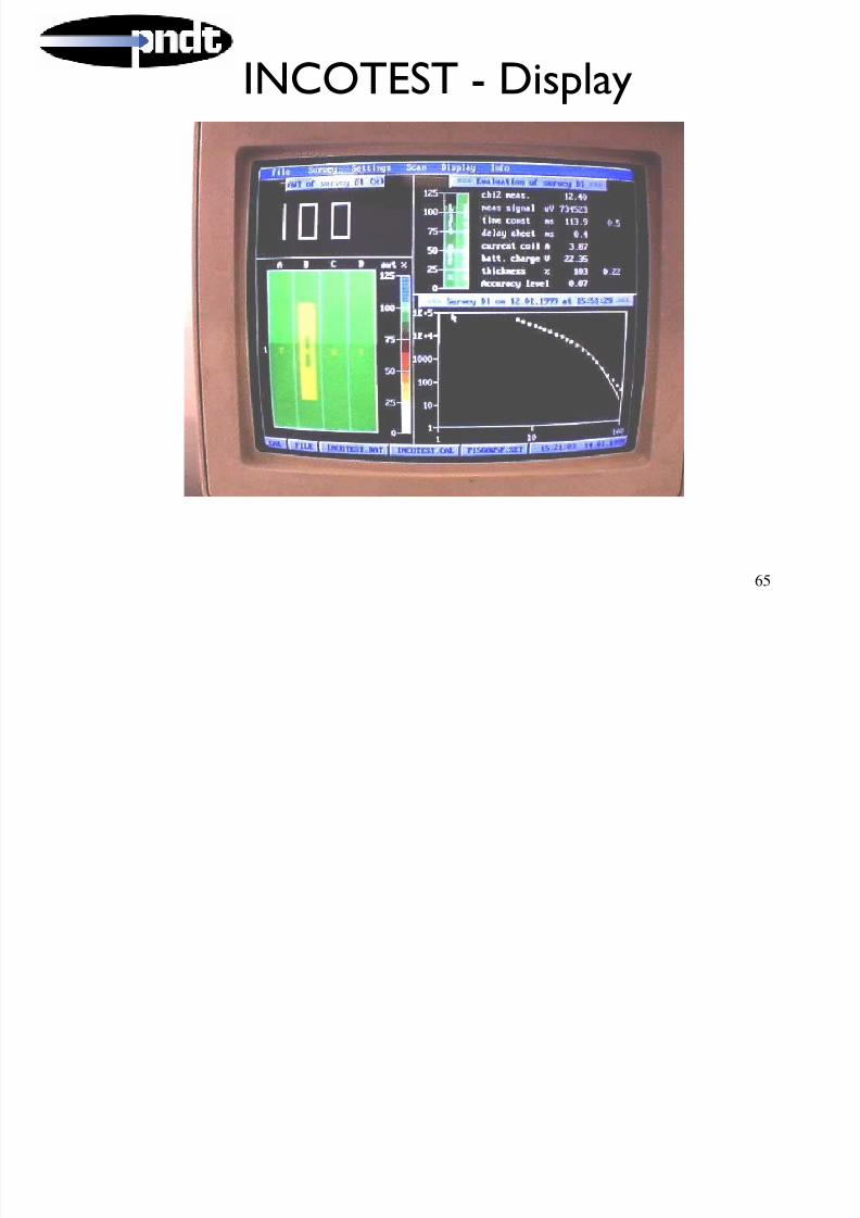
INCOTEST - Display
8/6/2019 All Techniques - In Brief
http://slidepdf.com/reader/full/all-techniques-in-brief 65/87
65
p y
Contact Measurements
8/6/2019 All Techniques - In Brief
http://slidepdf.com/reader/full/all-techniques-in-brief 66/87
66
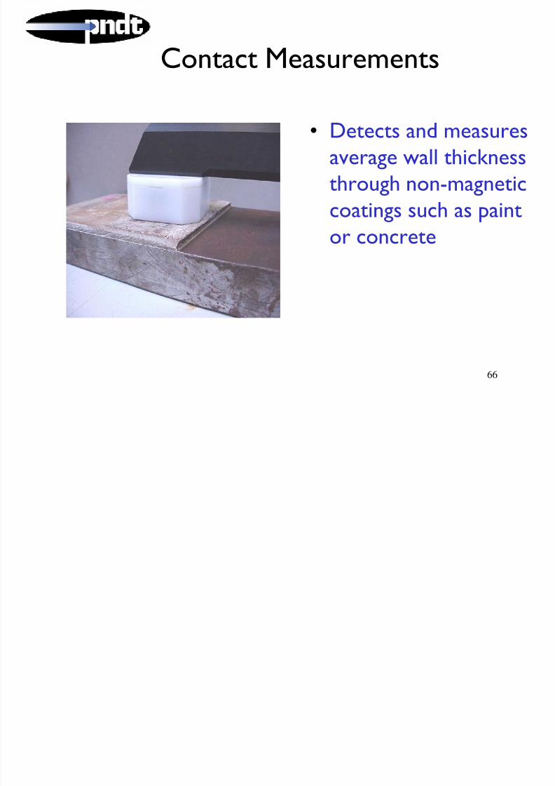
Contact Measurements
• Detects and measures
average wall thicknessthrough non-magnetic
coatings such as paintor concrete

8/6/2019 All Techniques - In Brief
http://slidepdf.com/reader/full/all-techniques-in-brief 67/87
Contact Measurements

8/6/2019 All Techniques - In Brief
http://slidepdf.com/reader/full/all-techniques-in-brief 68/87
68
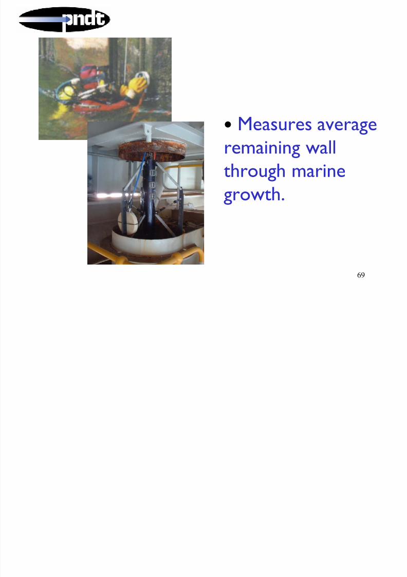
• Measures averageremaining wall
thickness onexternally corroded
surfaces
Contact Measurements
8/6/2019 All Techniques - In Brief
http://slidepdf.com/reader/full/all-techniques-in-brief 69/87
INCOTEST - Summary

8/6/2019 All Techniques - In Brief
http://slidepdf.com/reader/full/all-techniques-in-brief 70/87
70
• No requirement to remove insulation
• Fast
• Gives average wall thickness over a footprint (does notdetect isolated pitting)
• Detects both internal and external corrosion / erosion• Suitable for contact and non-contact applications
• Accurate
• Cost effective

8/6/2019 All Techniques - In Brief
http://slidepdf.com/reader/full/all-techniques-in-brief 71/87
71
Portable Digital Radiography
Applications / Features / Benefits

8/6/2019 All Techniques - In Brief
http://slidepdf.com/reader/full/all-techniques-in-brief 72/87
72
>Refineries for wall thickness measurement and corrosion
>Remote area pipelines
>On board of offshore platforms, submarines, airplanes,
>Railways trucks
>Museum and archeological
Testing on remote and difficult to reach locations
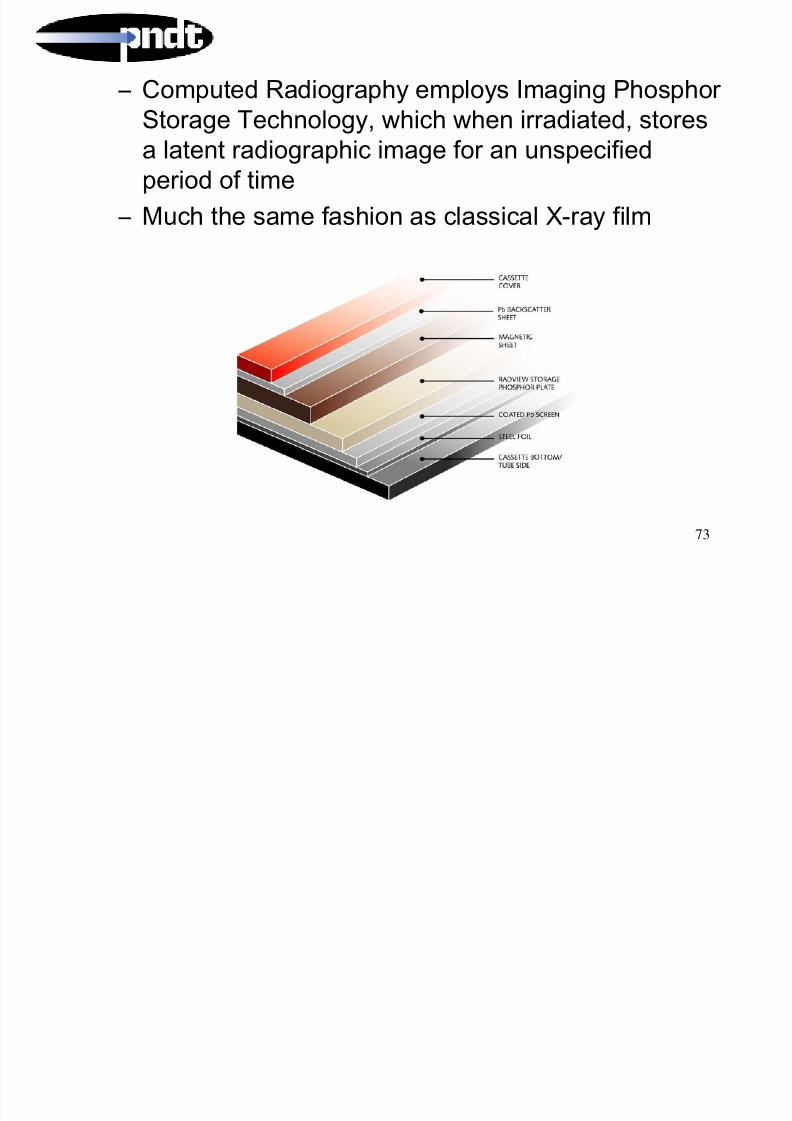
– Computed Radiography employs Imaging Phosphor
8/6/2019 All Techniques - In Brief
http://slidepdf.com/reader/full/all-techniques-in-brief 73/87
73
p g p y p y g g p
Storage Technology, which when irradiated, storesa latent radiographic image for an unspecified
period of time
– Much the same fashion as classical X-ray film

8/6/2019 All Techniques - In Brief
http://slidepdf.com/reader/full/all-techniques-in-brief 74/87
74
Raw ImageRaw ImageContrast enhancementContrast enhancement
by window/levelby window/levelSharpeningSharpeningZoom inZoom inEmboss in ROIEmboss in ROIZoom ROIZoom ROI

8/6/2019 All Techniques - In Brief
http://slidepdf.com/reader/full/all-techniques-in-brief 75/87
75
KernelsStandard
Smooth
Sharp
Emboss

8/6/2019 All Techniques - In Brief
http://slidepdf.com/reader/full/all-techniques-in-brief 76/87
76
Wall Thickness measurement software :

8/6/2019 All Techniques - In Brief
http://slidepdf.com/reader/full/all-techniques-in-brief 77/87
77
Wall Thickness measurement software :
Summary

8/6/2019 All Techniques - In Brief
http://slidepdf.com/reader/full/all-techniques-in-brief 78/87
78
Computed Radiography> Portable CR system
> Have digital images available on the spot> Transports easily between sites and into remote areas
> Dynamic range much higher than film or paper
> no retakes by bad exposure, different thickness in one shot…
> Phosphor plates are reusable
> no film or paper needed : consumable cost saving
> No chemicals, no darkroom
> cheaper infrastructure

8/6/2019 All Techniques - In Brief
http://slidepdf.com/reader/full/all-techniques-in-brief 79/87
79
Tank Floor Inspection
Mk 2 Floorscanner
Tank Floor Inspection

8/6/2019 All Techniques - In Brief
http://slidepdf.com/reader/full/all-techniques-in-brief 80/87
80
pFloorscanners - How does it work?
Magnetic Floorscanners operate on the principle that localised metal loss due to
corrosion pitting in magnetised floor plates produces an anomaly in the fields
above the plate. Magnetisation is achieved by scanning a powerful C-Magnet overthe floor plate. The flux leakage anomalies are detected by an array of sensorsbetween the poles of the magnet
Conveyor Belt

8/6/2019 All Techniques - In Brief
http://slidepdf.com/reader/full/all-techniques-in-brief 81/87
81
Laser Profile Systems

8/6/2019 All Techniques - In Brief
http://slidepdf.com/reader/full/all-techniques-in-brief 82/87
82
Example of raw data
16.5
17
17.5
18
18.5
19
19.5
20
20.5
0 50 100 150 200 250 300 350
3
5
6
7
Top and bottom belt profiles with

8/6/2019 All Techniques - In Brief
http://slidepdf.com/reader/full/all-techniques-in-brief 83/87
83
p p
overall belt thickness

8/6/2019 All Techniques - In Brief
http://slidepdf.com/reader/full/all-techniques-in-brief 84/87
84
Internal LaserProfiling
Crawler

8/6/2019 All Techniques - In Brief
http://slidepdf.com/reader/full/all-techniques-in-brief 85/87
85
Camera / Video SystemsCombination UT
Thickness and videoprobe

8/6/2019 All Techniques - In Brief
http://slidepdf.com/reader/full/all-techniques-in-brief 86/87
86
Internal CaissonVideo System

8/6/2019 All Techniques - In Brief
http://slidepdf.com/reader/full/all-techniques-in-brief 87/87
87