all you need to know about tribander antennas & …
TRANSCRIPT
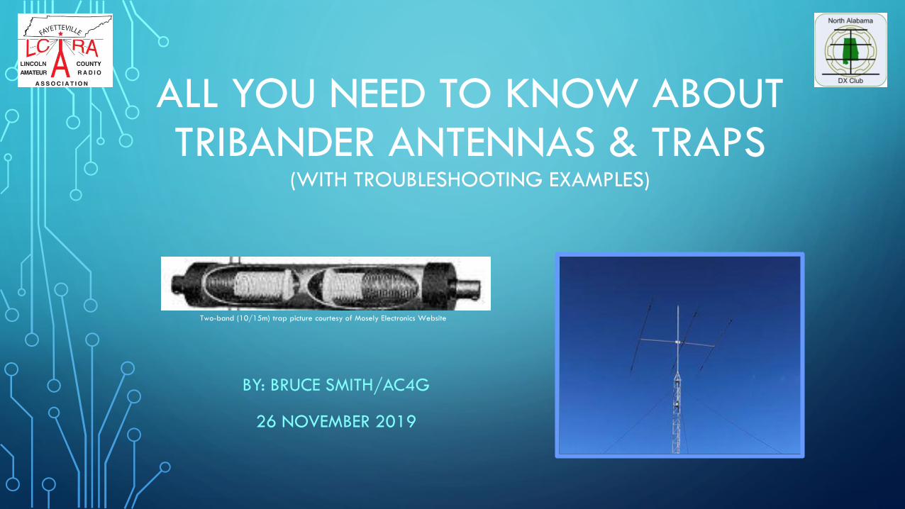
ALL YOU NEED TO KNOW ABOUT TRIBANDER ANTENNAS & TRAPS
(WITH TROUBLESHOOTING EXAMPLES)
BY: BRUCE SMITH/AC4G
26 NOVEMBER 2019
Two-band (10/15m) trap picture courtesy of Mosely Electronics Website
DISCUSSION TOPICS
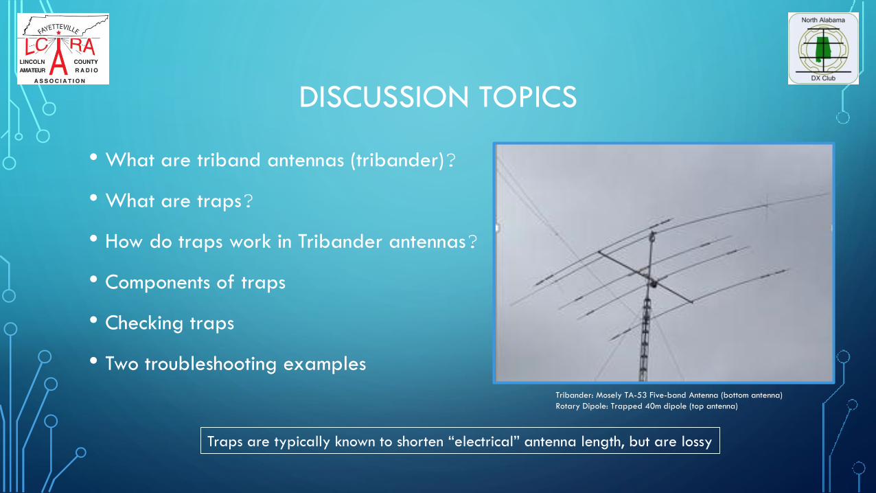
• What are triband antennas (tribander)?
• What are traps?
• How do traps work in Tribander antennas?
• Components of traps
• Checking traps
• Two troubleshooting examples
Traps are typically known to shorten “electrical” antenna length, but are lossy
Tribander: Mosely TA-53 Five-band Antenna (bottom antenna)
Rotary Dipole: Trapped 40m dipole (top antenna)

AMATEUR RADIO ANTENNAS (1 OF 2)
• HF antennas are well designed, but occasionally have electro-mechanical failures
• Monoband Yagi HF antennas (Hygain, Cushcraft, Telrex, KLM, Force-12, Ham-Pro, etc.) perform well, but
are limited to one band, have much Gain, good directivity, and great Front to Back rejection
• Quad antenna are multiband HF antennas … may be home-made or purchased from Cubex or other
manufacturers, but are fragile – hams say that “quads opens and closes the band(s)” - Bill Orr (W6SAI)
in his book about cubical quads, said “a two-element cubical quad is equal to a pair of 2 element
beams”
• Self-adjusting HF multi-band antennas such as SteppIR perform well, but can have electro-mechanical
problems with the element expansion motor (expensive electro-mechanical stepper motor)
Note: Hygain, Cushcraft,
Mosely, Telrex, Ham-pro,
KLM, Cubex, SteppIR, etc.
are registered trademarks
of antenna suppliers&
manufacturers

AMATEUR RADIO ANTENNAS (2 OF 2)
• Many HF multiband antennas use traps to allow for resonance on multiple bands.
• Tribander and Five-bander antennas (Mosely, Hygain, Wilson System I II or III, Cushcraft, KLM,
etc.) provide 3 or 5 band capability have traps, but sometimes have trap issues
This discussion will delve into the Tribander and its primary component - the Trap
Note: Hygain, Cushcraft,
Mosely, Telrex, Ham-pro,
KLM, Cubex, SteppIR, etc.
are registered trademarks
of antenna suppliers&
manufacturers
TRIBANDER ANTENNA CHARACTERISTICS (1 OF 2)
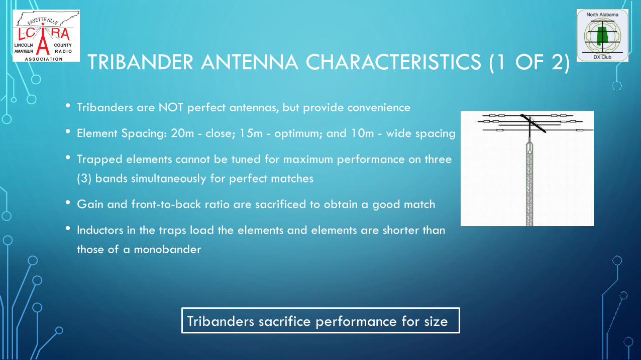
• Tribanders are NOT perfect antennas, but provide convenience
• Element Spacing: 20m - close; 15m - optimum; and 10m - wide spacing
• Trapped elements cannot be tuned for maximum performance on three
(3) bands simultaneously for perfect matches
• Gain and front-to-back ratio are sacrificed to obtain a good match
• Inductors in the traps load the elements and elements are shorter than
those of a monobander
Tribanders sacrifice performance for size
TRIBANDER ANTENNA CHARACTERISTICS (2 OF 2)
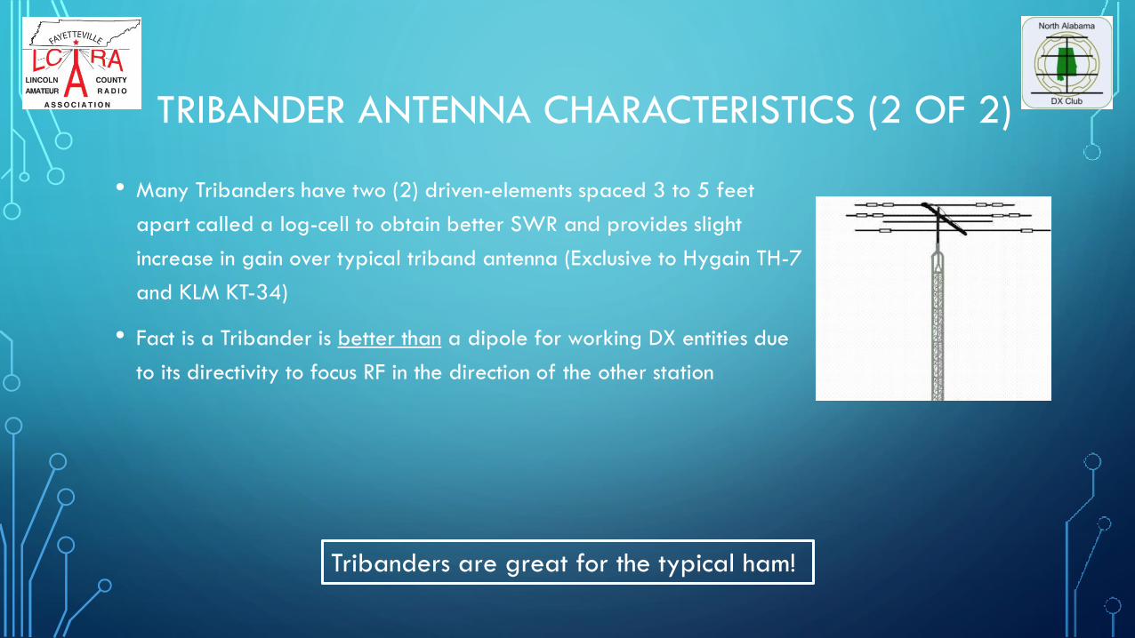
• Many Tribanders have two (2) driven-elements spaced 3 to 5 feet
apart called a log-cell to obtain better SWR and provides slight
increase in gain over typical triband antenna (Exclusive to Hygain TH-7
and KLM KT-34)
• Fact is a Tribander is better than a dipole for working DX entities due
to its directivity to focus RF in the direction of the other station
Tribanders are great for the typical ham!

IS A MONOBANDER BETTER THAN TRIBANDER?- TESTING CONDUCTED TO SEE TRAP LOSSES -
• N4JA(sk) tested a monobander and tribander in the early-2000’s to put to bed a myth
that a monobander is significantly better than a tribander having equal boom lengths
• Test setup: Two 56 feet towers spaced 100 feet apart over equal: terrain; same
antenna heights; boom lengths; frequency; coax length; and power level in 20m band
• Tower 1: Hygain 204-BA 4el Monobander w/ 26 feet boom
• Tower 2: Hygain TH-6 DXX 6 Element trapped tribander w/ 24 feet boom
• Transmitted signal: Carrier of 10 watts and held constant as antennas were “hot”
switched several times to several DX stations and one local amateur 5 miles away
• Results: No difference in signal reception by DX stations & no difference as seen by
Local station during dead 20m band [ability to see one dB difference on analog meter
used]
Conclusion: Tribander works as well as Monobander on 20m
Versus

LET’S LOOK INTO THE MAJOR COMPONENT OF THE TRIBANDER – THE TRAP

TRIBANDER TRAP ANTENNAS
• A popular way of fabricating a multiband antennas is to install parallel tuned circuits called
traps i.e. a series of ¼ wave elements joined together making a ½ wave element
• Quarter (1/4) wave elements may be broken at predetermined intervals with Insulators;
Terminating the tubing; or Installing parallel resonant circuits
• When a certain amount of capacitance is connected in parallel with a certain amount of
inductance, a very high resistance (impedance Hi-Z) results at a certain frequency
= high impedance (looks like an open circuit)RF(? frequency)

TRIBANDER TRAP ANTENNAS
• This “special high resistance” resistor (high impedance L/C) designed to work at narrow band
of frequencies [acts as an insulator]
• Other frequencies above and below this frequency exhibit opposite conditions at a very low
resistance (low impedance) [looks like a short circuit]
High
Impedance
Low
Impedance

TRAP RESONANCE
• Traps that resonate INSIDE the amateur bands – Each L/C combination is
resonant & presents a high impedance, behaving as an insulator
• Traps that resonate OUTSIDE the amateur bands – Trap behaves as an
inductor or capacitor where inductive loading electrically lengthens the
antenna or capacitive loading to shorten the electrical length of an antenna
• Additional traps can always be added to cover additional bands
• Efficiency of a trap system depends on Q values of tuned circuits; Q=2 pi f
L/R
• Low-loss, high Q coils should be used and capacitor losses low as possible
“Q” (Quality) is the ratio of
inductance (L) to resistance (R)
defining coil efficiency
Higher Q value results in lower losses and better suitability as RF inductor

TRAPS FOR TRIBANDER DESIGNS
• Tribanders usually have at least six parallel circuits (L/C) – but depends on number of elements of
the antenna (BW, Directivity, FB rejection, etc.) and the antenna brand
• The trap’s resonant circuit operating the highest frequency is nearest the antenna center closest to
the boom (10m traps closest to the boom); while the other end of the assembly another resonant
circuit is found operating on the next lower frequency (15m or 20m) closest to the end of element
[Reference trap schematic coming up in a few slides]
• Individual traps can be measured with VOM by measuring continuity or checked w/ Grid Dip
Meter or antenna analyzers (Discussed later)
• Due to the circuitry of trap-type antennas, any malfunction on the highest resonant frequency may
also cause the antenna to operate incorrectly on the lower resonant frequencies and vice versa
10/15m
Antenna Boom
28 Mhz (highest
frequency
10/15m
Single Element (Director, Driven, or Reflector)
TrapTrap

HYGAIN TH7DXX WITH TRAPS SHOWN
Schematics courtesy of Hygain TH7DXX Manual
These traps are the same for the active elements (DE & Reflector), but
can be easily mixed up during the assembly process causing issues

EXAMPLES HOW TRAPS FUNCTION
• Example 1:
• Trap resonant in the amateur band: Antenna A=66 feet long; each L/C combination is
resonant in 7Mhz band. Because of resonance, the trap presents a high impedance to
antenna system. The affect is that the trap behaves as an insulator. Any lengths beyond
the trap are invisible without any affect; thus the antenna is length A (66 feet long).
• Example 2:
• Trap not resonant in the amateur band:
• Antenna 3.5 Mhz, A=90 feet long; each L/C combination is resonant in 6Mhz band.
Because of resonance, the trap act as inductors (or capacitance) to antenna system. The
affect is the traps lengthen (or shorten) the antenna making an antenna with a length of A
+ B (or A minus B…Reference picture)
Picture: Diagram of a
dipole or rotary
dipole
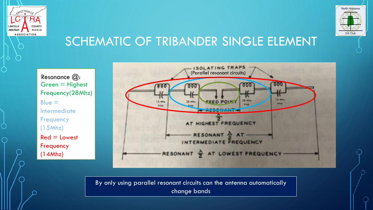
SCHEMATIC OF TRIBANDER SINGLE ELEMENT
Green = Highest
Frequency(28Mhz)
Blue =
Intermediate
Frequency
(15Mhz)
Red = Lowest
Frequency
(14Mhz)
Resonance @:
By only using parallel resonant circuits can the antenna automatically
change bands
(Parallel resonant circuits)
28 Mhz
trap
28 Mhz
trap15 Mhz
trap
15 Mhz
trap

TRAP RESONATE PARALLEL NETWORK FUNCTION ANALOGY
• EXAMPLE :
• Tribander excited with
21Mhz RF energy, only
the length of element
to the 21Mhz trap is
used – Trap is situated
¼ wave length from
the boom and is similar
to an open switch
• For 14Mhz excitation
energy, the 21Mhz
and 28 Mhz traps act
as closed switches and
uses the whole length
of the element(~33
feet)
MULTI-BAND ANTENNA excited with same frequency as trap, trap acts as
open (high impedance). ANTENNA excited with different frequency as trap,
trap acts as short (low impedance)
10m 15m
BOOM
S1 S2Excited w/ 15m RF Energy
20 m
15 m
10 mTRAPS
“Closed switch” “Open switch”
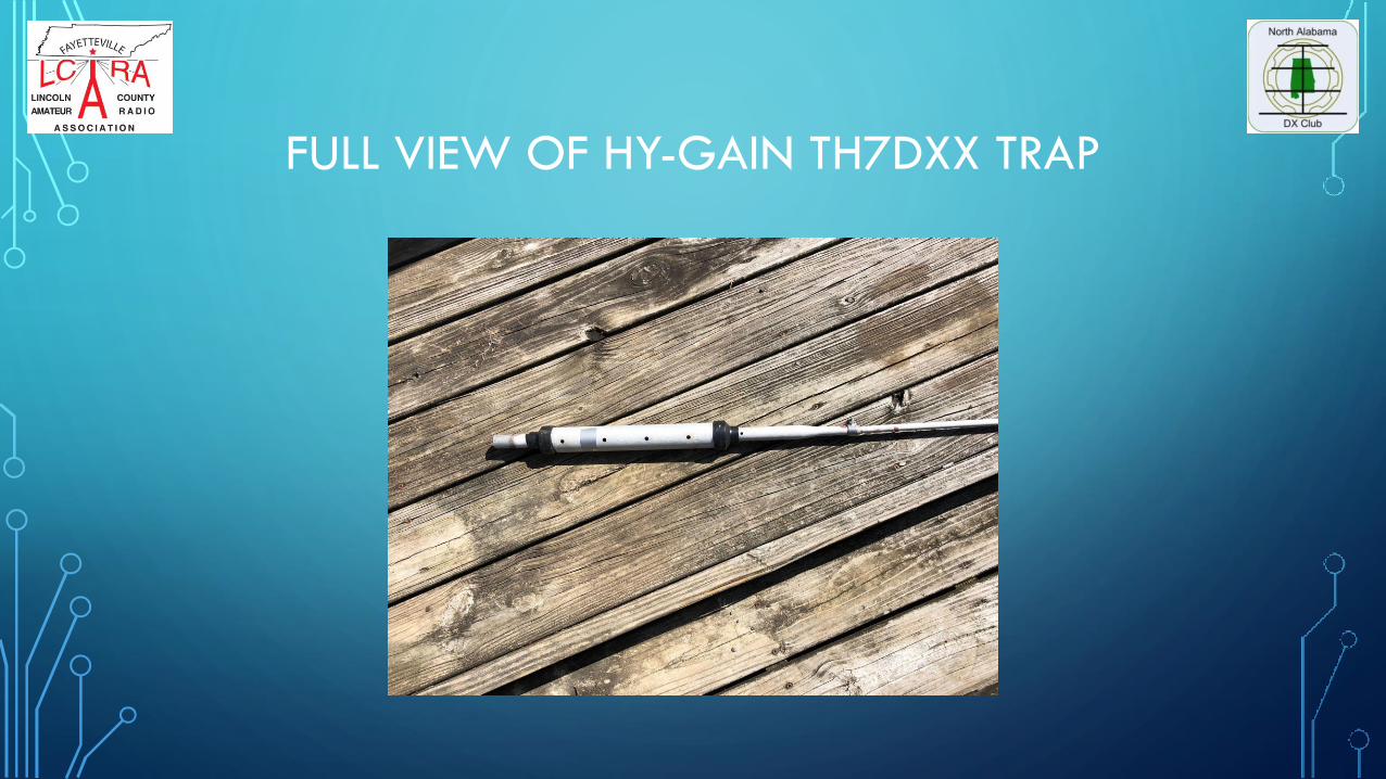
FULL VIEW OF HY-GAIN TH7DXX TRAP

TRAP ASSEMBLY DETAILS
End caps removed and requires removing rusty screw & bending tab to disassemble trap
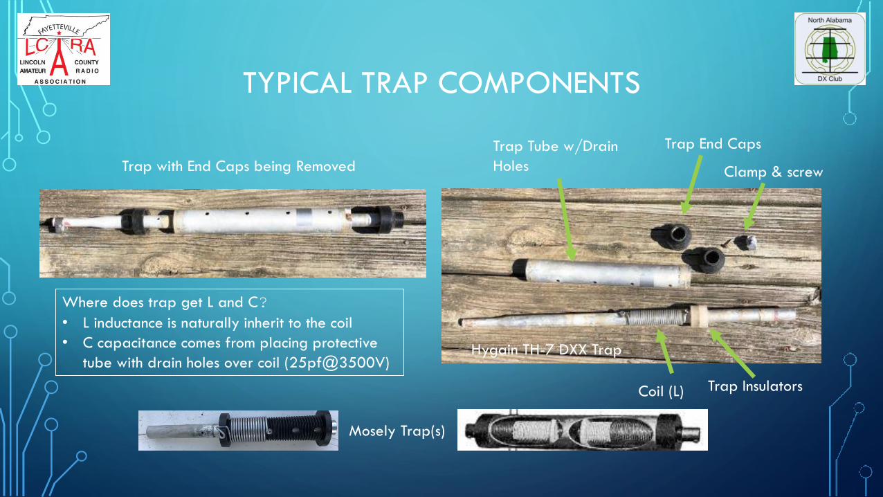
TYPICAL TRAP COMPONENTS
Coil (L)
Trap End CapsTrap Tube w/Drain
Holes
Trap Insulators
Trap with End Caps being Removed
Where does trap get L and C?
• L inductance is naturally inherit to the coil
• C capacitance comes from placing protective
tube with drain holes over coil (25pf@3500V)Hygain TH-7 DXX Trap
Mosely Trap(s)
Clamp & screw

CHECKING TRAPS

SIGNS OF TRAP ISSUES
• Initial signs of tri-bander antenna problems may be attributed to higher than
normal SWR readings
• When checking SWR, use an accurate measuring instrument. Nothing should
be installed between the SWR meter and antenna except the connecting
transmission line (coax)
• Note: Some SWR instruments do not indicate minimum SWR at true resonant
frequency
High SWR clued me to check the traps

VARYING SWR INDICATORS
• Bad SWR nay indicate:
• Trap is faulty or mistuned
• Length of radiator has changed(possibly becoming shorter due to a loose clamp or corroded
connection at trap-element tubing)
• Mistake in the assembly
• Always troubleshoot a trap problem working from the highest frequency to the lowest
• If antenna works on the next lower band, then the trap is good
• If the next lower frequency does not function correctly, then the trap coil may be
open

INSTRUMENTS TO CHECK ID TRAPS
• Volt Ohmmeter can check continuity of the trap coil and other connections
• Grid Dip Meter (otherwise called Grid Dip Oscillator) measures resonant frequency
of unconnected RF circuits. GDO is a variable frequency oscillator that sends a small
amplitude RF signal through an exposed coil interacting with adjacent circuitry. When
the oscillator loses power due to being near a resonant circuit, a meter registers the
dip.
• Modern antenna analyzers can measure SWR dips of RF circuits at resonant
frequencies by sending small RF signal to the circuit. User can monitor frequency
readout of SWR dip.
Use GDM or Antenna Analyzer needed if characteristics of trap are unknown

USE RIG EXPERT ANALYZER TO CHECK ID TRAP
10cm loop connected to a Rig
Expert Antenna Analyzer ready to
conduct SWR sweep finding SWR
dip
Perform
SWR sweep
using your
Rig Expert
Antenna
Analyzer to
find SWR
dip. Dip is
located at
resonate
frequency.

RIG EXPERT ANALYZER TO CHECK ID TRAP
Need a 10cm loop connected
coaxially to a Rig Expert Antenna
Analyzer (per Rig Expert manual
Perform SWR sweep using your
Rig Expert Antenna Analyzer to
find SWR dip
Resonate Frequency
SWR Dip

RX (PARALLEL) CHART OF TRAP
NOT ACCURATE!

SMITH CHART OF TRAP
NOT ACCURATE!

GRID DIP METER (GDM) TO COUPLE TO TRAP & CHECK ID TRAPS
Capacitive coupling requires the tip of the
GDM slightly inserted into lower end of
aluminum tubing of the trap (see diagram)
Inductive Coupling
Capacitive Coupling
Measurements:
GDM frequency is lower than operational
frequency of a trap and the trap loads
the dip oscillator to lower its frequency
If readings within +/- 100 KHz the affect
is minimal – GOOD TRAP
Shorted turns or other defects will cause 1
or 2 MHz swing indicating a BAD TRAP
Inductive coupling measurements are as
shown using inductive pickup placing GDO
near the trap
Not Best Method: GDM produces quick dip that can be missed and cannot find resonant point
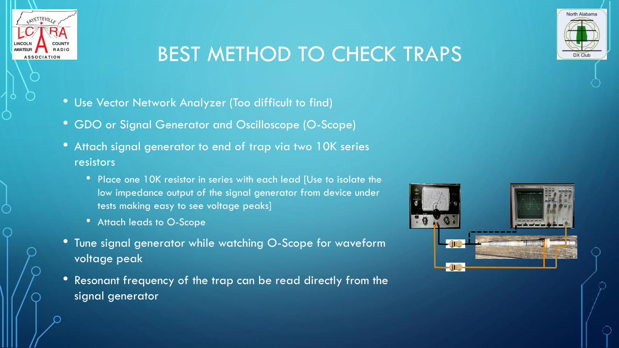
BEST METHOD TO CHECK TRAPS
• Use Vector Network Analyzer (Too difficult to find)
• GDO or Signal Generator and Oscilloscope (O-Scope)
• Attach signal generator to end of trap via two 10K series
resistors
• Place one 10K resistor in series with each lead [Use to isolate the
low impedance output of the signal generator from device under
tests making easy to see voltage peaks]
• Attach leads to O-Scope
• Tune signal generator while watching O-Scope for waveform
voltage peak
• Resonant frequency of the trap can be read directly from the
signal generator
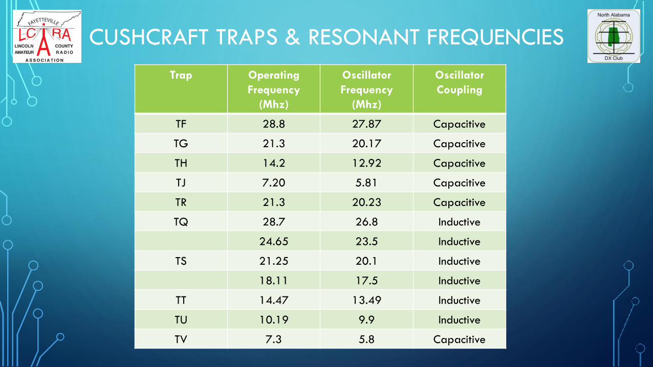
CUSHCRAFT TRAPS & RESONANT FREQUENCIES
Trap Operating
Frequency
(Mhz)
Oscillator
Frequency
(Mhz)
Oscillator
Coupling
TF 28.8 27.87 Capacitive
TG 21.3 20.17 Capacitive
TH 14.2 12.92 Capacitive
TJ 7.20 5.81 Capacitive
TR 21.3 20.23 Capacitive
TQ 28.7 26.8 Inductive
24.65 23.5 Inductive
TS 21.25 20.1 Inductive
18.11 17.5 Inductive
TT 14.47 13.49 Inductive
TU 10.19 9.9 Inductive
TV 7.3 5.8 Capacitive

AC4G TRAP TROUBLE-SHOOTING

DIRTY TRAPS CAN CAUSE TRAP ISSUES
• End caps & protective weather
preventions techniques tend to
break down with time
• Antenna traps tend to corrode
and get contaminated internally
over time
• Trap screws loosen
Traps need to be cleaned periodically

EXAMPLE 1: DIRTY TRAPS CLEANED TO RESTORE FUNCTION
• A few years ago, was having SWR problems with my Cushcraft D3W WARC Band
Rotary Dipole
• The tale-tale sign was high and fluctuating SWR on 30m band
• Lowered antenna to ground & checked feedline
• Disassembled traps to find insects and grass looking material inside traps and the
suspicious trap(s)
• Cleaned traps to restore antenna back to normal function
• Antenna exhibited flat, low SWR across the WARC bands

EXAMPLE 2: QUESTIONABLE TRI-BAND TRAP
• Reference picture on right
• Problem trap is from a Mosely
Classic 33 having issues
• Mosely traps are wound using
No. 10 wire on grooved forms
molded of high-impact
polystyrene
• VOM used to check coil wire
• Element along with trap casing
comprises the fixed
capacitance ~25pfVOM
Mosely CL-33 Trap

MOSELY TRI-BAND TRAP CAUSING 20M ISSUES
• Failure Investigation led to suspect issues with 10/15m trap on driven
element
• Trap coil was disassembled and was not burnt into (VOM measured
continuity)
• Further investigation revealed faulty rivet connection
• Rivet looks good, but no connection to tubing causing high SWR on 20m
band. Measured “no continuity” with Ohmmeter
• Drilled rivet head and removed rivet
• Cleaned area around rivet hole in trap tubing
• Re-riveted end of coil to trap tubing
Suspect rivet causing an issue

MOSELY TRI-BAND TRAP CAUSING 20M ISSUES
• Used Ohmmeter to ensure connection of coil end to tubing
• Reassembled trap component into trap & trap back onto antenna element
• SWR check using antenna analyzer and transceiver revealed working,
functioning 10/15m trap allowing 20m to work properly
• QSOs made w/ triband antenna using low during normal operating
• ~650 QSOs made w/ triband using high power (1KW) in both the 2019
CQWW SSB Contest & 2019 CQWW CW Contest operating on
10/15/20m
Grid Dip Meter or Antenna Analyzer was not needed since this
issue was due to faulty coil connection to the trap

MOSELY TRI-BANDER PERFORMING WELL
• ALL TRAPS checked,
cleaned, & new end
caps installed
• One trap rivet repaired
with new rivet
• Old rusty screws replaced
with stainless steel screws
to hold protective trap
tube in place
Traps
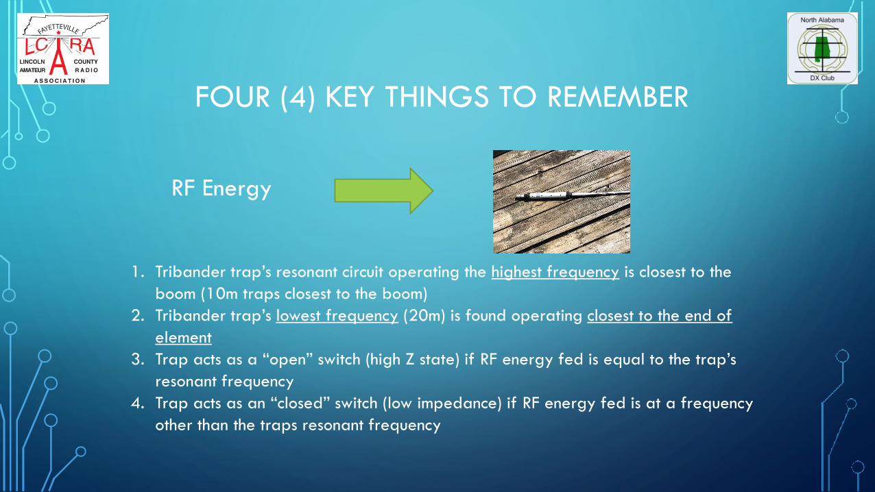
FOUR (4) KEY THINGS TO REMEMBER
RF Energy
1. Tribander trap’s resonant circuit operating the highest frequency is closest to the
boom (10m traps closest to the boom)
2. Tribander trap’s lowest frequency (20m) is found operating closest to the end of
element
3. Trap acts as a “open” switch (high Z state) if RF energy fed is equal to the trap’s
resonant frequency
4. Trap acts as an “closed” switch (low impedance) if RF energy fed is at a frequency
other than the traps resonant frequency
• Now you know all you need to know about tribander & traps…
• Almost every ham at one point in the hobby has owned or used a
tribander with good performance
• Tribanders can help DXers achieve DXCC & Honor Roll on multiple
bands if maintained [concept also applies to wire dipoles]
Conclusions
Continue to use those tribanders (new or old)
GUD DX!

REFERENCES
• ARRL Antenna Handbook
• ARRL Handbook
• W6SAI Antenna Handbook (Hard Cover)
• Other…Various internet articles
• http://www.mosley-electronics.com
• http://www.hy-gain.com
• http://www.arrl.org
• Coaxial Trap Designer by VE6YP (Tony Fields)

QUESTIONS?

TRAP TEST SET-UP

LIVE DEMO CHECKING TRAP
• Items needed for demo:
• Rig Expert Antenna Analyzer with 10cm coil installed
• Trap
• Good ideas & recommendations