alma requirements working group overview
TRANSCRIPT

Gie Han Tan on behalf of the ALMA Requirements Working Group
ALMA Development WorkshopESO Garching, 3 - 5 June, 2019
ALMA requirements working group Overview

The ALMA Frontend & Digitizer Requirement Update WG is charged to
make a flow-down from the top-level requirements to system requirements,
which would be a matrix for the new development, especially for the ALMA
frontend and digitizer system.
ALMA Frontend & Digitizer Requirements Working Group
ALMA Development Roadmap
document (Carpenter et al.
2018) defines a new long-term
development strategy for the
upgrade of hardware, software,
and analysis tools to enhance
the ALMA observation
capabilities for next decades. http://www.almaobservatory.org/wp-
content/uploads/2018/07/20180712-alma-development-roadmap.pdf

• Primary Goal– Gather input from community to determine the expected
technical performance on the timescale of 4-6 years– Consider scientific use cases and trade-offs associated with
various technical choices should be considered. • Science input to be gathered by ALMA Observatory Scientist via IST
(Integrated Science Team)
– Draft an update of the Front-End & Digitizer related requirements flowed down from Science through System level to sub-system level requirements,
Charge 1

• Secondary Goal– Based on technical and science inputs,– Draft an update of the remaining requirements flowing down
from Science through System level to sub-system level requirements
• The working group shall achieve the same level of breadth and depth of information from each region.
• Implementation not in scope of this WG => AMT (ALMA Management Team)
Charge 2

• Support from expert community is essential!
Working Group Members
Project Team Role Project Team Member(s)
Responsibilities
Project Systems Engineer &
Front End Expert
Nick Whyborn →
Shin’ichiro
Asayama
Requirements flow-down; gate review
planning, preparation and participation;
technical and trade-off analysis
EU Project Coordinator & Front
End Expert
Gie Han Tan Coordination with Executive internal
stakeholders, provide expert advise
EA Project Coordinator & Front
End Expert
Shin’ichiro
Asayama
Coordination with Executive internal
stakeholders, provide expert advise
NA Project Coordinator &
Front End Expert
Kamaljeet Saini Coordination with Executive internal
stakeholders, provide expert advise
Science Expert John Carpenter Broad science impact/interest, community
interest
Science Expert Todd Hunter Science System Expert from NA
Science Expert Neil Phillips Science System Expert from EU
Science Expert Hiroshi Nagai Science System Expert from EA

Date Milestone
2018-11-26 Kick-off
2019-01-23 F2F meeting at Santiago
2019 3-6 Jun ESO Dev. WS, followed by F2F meeting on Jun 6 2019
2019 Mid Jun Draft requirements to AMT
2019-06-30 Draft sent to IET and IST for review
2019-09 External review
2020-01 Implications to AMT/IxT meeting
2020 Q1 Sent to ASAC for comment
2020-04 Approval by Board
Charges: Schedule

ALMA Development Roadmap
3 fundamental science drivers for ALMA developments over the next decade.
Current priorities as based on scientific merit and technical feasibility, are:� to broaden the receiver IF bandwidth by at least a factor two, and� to upgrade the associated electronics and correlator.
Continued exploration of the following development paths are supported:� Extending the maximum baseline length by a factor of 2-3.� Focal plane arrays for ALMA’s wide-field speed.� Increasing the number of 12-m antennas, and a large single dish telescope.
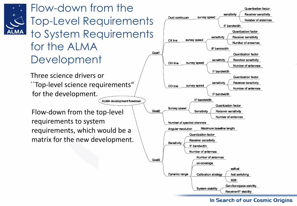
Flow-down from the Top-Level Requirements to System Requirements for the ALMA Development
Flow-down from the top-level requirements to system requirements, which would be a matrix for the new development.
Three science drivers or ``Top-level science requirements“for the development.

• Science Drivers– Detect spectral lines (e.g., CO, CII, OIII) and dust
continuum from galaxies at z>2 at a rate of 1-2 galaxies per hour
• Requirements (tentative) for FE & Digitizer– x2.5 bandwidth increase with 3x2-bit quantization (or
x2.1 increase with 4x4-bit quantization) to detect z>2 galaxies with CO lines (assuming no increase in the receiver sensitivity)
– No change required for continuum sensitivity
Goal 1: Origin of galaxies

Goal 2: Origin of chemical complexity
• Science Drivers– Trace complex organic molecules in the star/planet
formation process by performing full-band frequency scans at a rate of 2-4 protostars per day.
• Requirements (tentative) for FE & Digitizer– 4 times increase in number of spectral channels to
achieve ~0.2 km s-1 velocity resolution with 1.875-GHz width of a spectral window for a given sensitivity with 3x2-bit quantization (or x3.2 increase with 4x4-bit quantization)
– Increase in instantaneous IF bandwidth also essential

Goal 3: Origin of planets
• Science Drivers– Image protoplanetary disks in nearby (150 pc) star formation
regions to resolve the Earth forming zone (~1 au) in the dust continuum at wavelengths shorter than 1mm.
• Requirements for FE & Digitizer– Basic requirement is to support longer baselines
• validate current Line Lengths Correctors and Data Transmission System– Improved bandwidth will increase continuum sensitivity
• expanding the number of disks that can be imaged, and (partially) mitigating the challenges in calibrating data from longer baselines
– Improved receiver sensitivity and quantization efficiency will improve line sensitivity, enabling the detection of kinematic signatures of protoplanets, and imaging of disk spectral line polarization

• Current ALMA Scientific Specifications and Requirements, version A, and ALMA System Technical Requirements, version C, mix up science and technical requirements at different levels– E.g. Science requirement #160 defines receiver temperatures: a clearly
technical requirement that shall be derived from instrument flux sensitivity– System Technical requirement #290 specifies a limit on spurious at the
interface between LO and RF mixer: a requirement which should be within a Front-end sub-system Technical Specification
• In some cases System Technical requirements lack a higher level Science requirement (orphans)
Ø A systematic flow-down is needed supported by• Requirement tree (showing traceability)• System performance budgets (allowing allocation of requirements to sub-systems)• In some cases where no formal Science requirement exists, engineering, assumptions
have to be made for System Technical requirements
A more systematic flow-down from Science Requirements to System Requirements

Flow-Down to the ALMA System Technical Requirements
SCI #070
Spectral dynamic range
SCI #080
Flux sensitivity
SYS #010
Point source sensitivity - Continuum
SCI #100
Antenna complement
SCI #110
Antenna surface
SCI #150
Antenna aperture efficiency
ITU-R RA.769-2
Protection criteria used for radio astronomical
measurements
ITU-R RA.1272-1
Protection of radio astronomy
measurements above 60 GHz from ground
based interference
SYS #020
Threshold interference levels
- Continuum
SYS #025
Threshold interference levels
- Spectral line
SYS #015
Point source sensitivity - Spectral line
Applicable documents to System Technical Requirements ALMA Scientif ic Specifications and Requirements ALMA-90.00.00.00-001-A- SPE
SYS #270
IF / anti-aliasing filters: stopband
response
SYS #290
Spurious signals on LO sidebands
Front End Specifications ALMA-40.00.00.00-001-B-SPE
SCI #300
Amplitude Fluctuations
SYS #291
Stability of spurious signals
ALMA System Technical Requirements ALMA-80.04.00.00-005-D-SPE
A0
New requirement
A0
Updated requirement
FE #xxx
Spurious signals on 1st Local
Oscillator
Back End Specifications ALMA-50.00.00.00-092-B-SPE
BE #xxx
Spurious signals on 2nd LO / ADC
clock
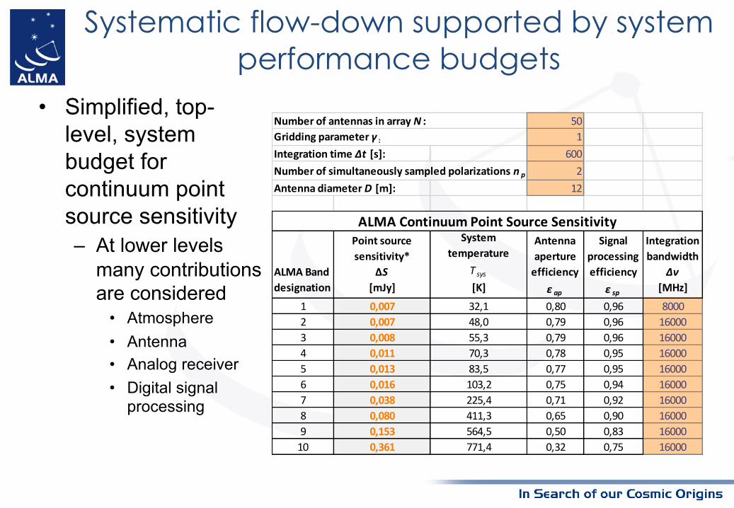
• Simplified, top-level, system budget for continuum point source sensitivity– At lower levels
many contributions are considered
• Atmosphere• Antenna• Analog receiver• Digital signal
processing
501
Integration time Δt [s]: 600Number of simultaneously sampled polarizations n p : 2Antenna diameter D [m]: 12
ALMA Band designation
Point source sensitivity*
ΔS[mJy]
System temperature
Tsys
[K]
Antenna aperture
efficiencyε ap
Signal processing efficiency
ε sp
Integration bandwidth
Δν[MHz]
1 0,007 32,1 0,80 0,96 80002 0,007 48,0 0,79 0,96 160003 0,008 55,3 0,79 0,96 160004 0,011 70,3 0,78 0,95 160005 0,013 83,5 0,77 0,95 160006 0,016 103,2 0,75 0,94 160007 0,038 225,4 0,71 0,92 160008 0,080 411,3 0,65 0,90 160009 0,153 564,5 0,50 0,83 1600010 0,361 771,4 0,32 0,75 16000
Number of antennas in array N :Gridding parameter γ :
ALMA Continuum Point Source Sensitivity
Systematic flow-down supported by system performance budgets

• Current ALMA Scientific
Specifications and Requirements,
version A, contain no parent
requirement for internally generated
spurious signals
– This gap can be filled by an
explicit, well justified,
assumption
– E.g. by referencing to
Recommendation ITU-R
RA.769-2 Protection criteria used for radio astronomical measurements
– Based on the formalism
presented in this ITU
Recommendation self-generated
spurious limits can be derived
Assumptions when lacking Science requirements: Self-generated RFI
Temperature
ΔT[mK]
Power spectral
density
ΔP[dB(W/Hz)]
Input
power
ΔP H
[dBW]
pfd
S H Δf[dB(W/m2)]
Spectral pfd
S H
[dB(W/(m2 · Hz))] Comments
(1) (2) (3) (4) (5) (6) (7) (8) (9) (10)
35000 30,5 18 32 6,40 -251 -216 -163 -208 ALMA Band 1 - lower band edge43000 500 25 65 2,85 -254 -207 -153 -210 from ITU-R RA.769-248000 500 30 65 3,00 -254 -207 -152 -209 from ITU-R RA.769-250000 30,5 18 32 6,40 -251 -216 -160 -205 ALMA Band 1 - upper band edge67000 30,5 18 47 8,32 -249 -215 -157 -201 ALMA Band 2 - lower band edge84000 30,5 18 60 9,99 -249 -214 -154 -199 ALMA Band 3 - lower band edge88600 1000 12 30 0,94 -259 -209 -148 -208 from ITU-R RA.769-295000 30,5 18 47 8,32 -249 -215 -154 -198 ALMA Band 2 - upper band edge116000 30,5 18 60 9,99 -249 -214 -151 -196 ALMA Band 3 - upper band edge125000 30,5 18 82 12,80 -248 -213 -149 -194 ALMA Band 4 - lower band edge150000 1000 14 30 0,98 -259 -209 -144 -204 from ITU-R RA.769-2163000 30,5 18 82 12,80 -248 -213 -147 -192 ALMA Band 5 - lower band edge211000 30,5 18 105 15,75 -247 -212 -144 -189 ALMA Band 5 - upper band edge211000 30,5 20 136 19,97 -246 -211 -143 -188 ALMA Band 6 - lower band edge220000 1000 20 43 1,41 -257 -207 -139 -199 from ITU-R RA.769-2265000 1000 25 50 1,68 -256 -206 -136 -196 from ITU-R RA.769-2275000 30,5 20 136 19,97 -246 -211 -140 -185 ALMA Band 6 - upper band edge275000 30,5 25 219 31,24 -244 -209 -139 -183 ALMA Band 7 - lower band edge373000 30,5 25 219 31,24 -244 -209 -136 -181 ALMA Band 7 - upper band edge385000 30,5 25 292 40,59 -243 -208 -134 -179 ALMA Band 8 - lower band edge500000 30,5 25 292 40,59 -243 -208 -132 -177 ALMA Band 8 - upper band edge602000 30,5 25 261 36,62 -243 -208 -131 -176 ALMA Band 9 - lower band edge720000 30,5 25 261 36,62 -243 -208 -129 -174 ALMA Band 9 - upper band edge787000 30,5 25 344 47,25 -242 -207 -128 -172 ALMA Band 10 - lower band edge950000 30,5 25 344 47,25 -242 -207 -126 -171 ALMA Band 10 - upper band edge
Threshold levels of interference detrimental to radio astronomy spectral-line observations
Centre
frequency
f c
[MHz]
Assumed
spectral line
channel
bandwidth
Δf[kHz]
Minimum
antenna noise
temperature
T A
[K]
Receiver noise
temperature
T R
[K]
System sensitivity Threshold interference levels

Design driver for FE & Digitizerand Technical Consideration

• Wider RF/IF bandwidth:– Receiver: Optics, RF CLNA(B1-3), SIS mixer (B4-10), IF CLNA– LO source– IF system and Digitizer
• Sensitivity:– Trx (optimizing Trx, although ALMA is already pretty good)– Bandwidth (for continuum observation)– Quantization bits
• Amplitude Dynamic range:– Receiver and IF system linearity– Quantization bits– Electronic stability– Passband gain variations.
Design driver for FE & Digitizer

Wide IF/RF Technical Trade-offs
Wide RF:• NAOJ+: High-Jc SIS mixers (B7+8, 6+7), 4-20 GHz, waveguide design (B2+3, 6+7, 7+8)
• ASIAA+: 30-50 GHz HEMT receiver, IF 4-20 GHz (goal 4-24 GHz)
• ESO/NAOJ+: ALMA band 2 HEMT RX -> RF 67-116 GHz (B2+3), IF 4-16 (18) GHz
Wide IF:• NAOJ: remove isolator, improve SIS mixer impedance (High-Jc)
• SMA: wideband isolator
• IRAM (, SRON): remove isolator, improve CLNA matching
• NRAO: a wider Band 6 receiver with LNF amplifiers and NRAO-UVML mixers, edge mode
isolators from Harvard-Smithsonian
Considerations:• A few kelvin tradeoff between wideband and narrowband designs
• IF gain variation requirement will depend on sampler bandwidth and precise
architecture

Sensitivity Consideration• Trx
– CLNA (HEMT) and SIS technology has already achieved nearly theoretical limits
(quantum limits) at device level
• External optics, waveguide losses are dominant factor of the receiver noise at
low frequency bands
– Some improvement at higher frequencies (Trx, 2SB on Band 9/10)
• Wideband IF
– Wider IF will offer increased continuum sensitivity and more efficient spectral
surveys
– No sensitivity benefit for any specific spectral line
– Careful trade-off needed between increased IF range vs. Trx
• Agreement with IST and ASAC that the aim is to optimize the speed of the observations given a
mixture of single-tuning spectral line projects versus multi-spectral tuning/continuum projects
• Quantization bits
– Sensitivity loss by 2-level (1-bit), 4-level (2-bit), 8-level (3-bit) or 16-level (4-bit)
quantized sampling become 0.637, 0.88, 0.963 or 0.988, respectively.
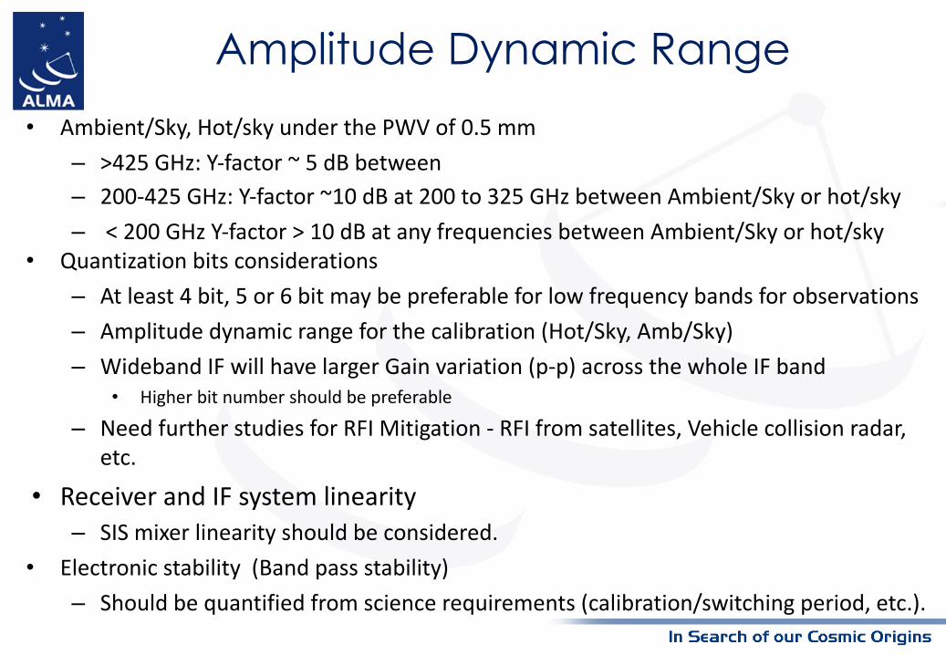
Amplitude Dynamic Range• Ambient/Sky, Hot/sky under the PWV of 0.5 mm
– >425 GHz: Y-factor ~ 5 dB between
– 200-425 GHz: Y-factor ~10 dB at 200 to 325 GHz between Ambient/Sky or hot/sky
– < 200 GHz Y-factor > 10 dB at any frequencies between Ambient/Sky or hot/sky• Quantization bits considerations
– At least 4 bit, 5 or 6 bit may be preferable for low frequency bands for observations
– Amplitude dynamic range for the calibration (Hot/Sky, Amb/Sky)
– Wideband IF will have larger Gain variation (p-p) across the whole IF band• Higher bit number should be preferable
– Need further studies for RFI Mitigation - RFI from satellites, Vehicle collision radar, etc.
• Receiver and IF system linearity– SIS mixer linearity should be considered.
• Electronic stability (Band pass stability)
– Should be quantified from science requirements (calibration/switching period, etc.).

Signal Dynamic Range, Passband IF variation and Quantisation Noise
Three critical parameters that drive ENOB versus sample-rate trade-off in the selection of digitizers and the choice of IF architecture.• Signal Dynamic Range
– The range of signal power levels that the IF chain has to cope with.– Signal power level changes during the observing sequence, and those that are
unchanged during the observation but that change from observation to observation (e.g. due to LO 1 changes), from band to band, and from frontend to frontend.
• Passband IF variation– This is the signal level variation across the passband due to ripple, gain-slopes etc.
The relevant bandwidth is that which pertains to the sampler input.• Quantisation Noise
– The noise that comes from the coarse quantisation typically employed.– The noise level relative to the wanted signal depends on the number of bits and the
signal level relative to the sampler level spacing.

Signal Dynamic Range
Source Dynamic range [dB]
Requiredquantizationefficiency
Notes
Sky brightness changes 3 96%Neil Phillips (private communication).IF level setting error 1 96%Combination of IF attenuator resolution and setting error.Sub-total: science targets 4 96%System Requirements #227.1 & #521
AtmCal calibration sequence 12 75%Hot load versus cold sky (Band dependent values).
IF level setting error 1 75%Combination of IF attenuator resolution and setting error.Sub-total: flux calibration 13 75%System Requirement #227.2
Solar observations 12 90%TBC Receiver detuning or optical attenu-ator.IF level setting error 1 90%Combination of IF attenuator resolution and setting error.Sub-total: solar observing 11 75%Provisional value, TBC.
• The digitizer must have sufficient bits to cope with this level change while meeting the quantisation noise contribution requirement. Not possible to use adjustable analog attenuator to compensate.
• A degraded SNR may be acceptable during AtmCal cycle.

Possible Digitizer Configurations• Down-converter (current ALMA
system)– Complex !– Gaps in passband coverage !– Spurious due multiple LO signals !
• Single wideband ADC– No gaps in passband "– Single sampling clock "– Might have spurious due to
interleaved ADCs #– Limited ENOB #
• Multi-rate scheme– No gaps in passband "– Might have spurious due to
multiple sampling clocks #– Limited ENOB #

Requirements for other systems

Requirements for other systems
These requirements are not for the scope of the FE & Digitizer requirements WG, however, they are coupled with the requirements of FE & digitizer.
• Calibration scheme– WVR, fast-switching and/or band-to-band transfer calibration would be a key.
• Increasing the number of 12-m antennas– Improving spectral line sensitivity and polarization sensitivity is also important to
understand the origin of planets– 9 additional antennas with more than 9-hours on-source time are required to achieve
high-fidelity imaging by imaging simulations
• Focal Plane Arrays: Significant increase in mapping speed presents an– A technical choice as a future upgrade.

Requirements for other systems – Cont.
These requirements are not for the scope of the FE & Digitizer requirements WG, however, they are coupled with the requirements of FE & digitizer.
• Digital Processing & Transmission– The digital processing to allow for large basebands and higher effective bandwidth
coverage– The correlator to process larger bandwidths at higher spectral resolution
• Expanding the baseline length by a factor of 2-3: ~30-50 km baselines to resolve 1 AU scale at a distance of 150 pc in band 7. – High stable LO and reference system are required.– Sampler clock
• Increased jitter requirements for digitizer clock

DTS, Tunable Filter Bank• DTS
– Data rate between antenna and correlator ~ 352 Gb/s• Assumptions
– ADC sample rate: 40 GS/s– Resolution: 4 bits– Polarization channels: 2– DTS overhead: 10 %
– Required data rate fits commercially available solutions very well• E.g. Ethernet based• Time stamping when using Ethernet etc. for DTS
Commercially available example• 40 x 10 Gbit/s• ~k€ 45,-excl. long distance fibre
• Tunable Filter Bank– COTS FPGAs available e.g. Intel (Altera) / Xilinx– Challenge is to design an architecture that is compatible with the current correlator
architecture (also used for NRAO CUP) and future, more advanced architectures (ALMA Memo 607)

• The flow-down from the top-level requirements to system requirements has been made.– Considered scientific use cases – Trade-offs associated with various technical choices
• Gather updates from community to determine the expected technical performance at this work shop!
Summary

Appendix

Increased IF/RF Bandwidth
The highest ALMA development priority as based on scientific merit and technical feasibility is:• to broaden the receiver IF bandwidth by at least a factor two, • to upgrade the associated electronics and correlator.
All science will benefit from wider bandwidths!- Wide IF will offer increased continuum sensitivity and more efficient
spectral surveys
- Wide RF offers the possibility to use a single receiver over wider bands, which increases efficiency, accuracy of results and flexibility of observations