alongside berth construction at thilafushi, kaafu atoll resort
TRANSCRIPT

MALDIVES PETROLEUM LINKS PVT LTD
Land and Marine Environmental Resource Group Pvt. Ltd lamer.com.mv | [email protected] | 330 5049
Report Prepared by LAMER Group Pvt Ltd
Hussein Zahir
Shahaama A. Sattar
Azim Musthag
ENVIRONMENTAL IMPACT ASSESSMENT REPORT Alongside berth construction at Thilafushi, Kaafu Atoll RESORT
September 30, 2020

Table of contents
Table of contents ............................................................................................................................. i
List of Tables ................................................................................................................................. iii
Table of Figures ............................................................................................................................ iv
Consultants Declaration ................................................................................................................. vi
Proponents Declaration ................................................................................................................. vii
1 Non-technical Summary .................................................................................................... viii
Background ............................................................................................................................... viii
Key impacts, mitigation measures and alternatives .................................................................. viii
............................................................................................................................................. ix
.............................. ix
2 Introduction ..................................................................................................................... 2-11
2.1 Purpose of the report and need for the EIA ............................................................. 2-11
3 Terms of Reference (ToR) .............................................................................................. 3-13
4 Project Setting ................................................................................................................. 4-14
5 Project Description .......................................................................................................... 5-19
5.1 Project Proponent ..................................................................................................... 5-19
5.2 The Project ............................................................................................................... 5-19
5.3 Need for the Project ................................................................................................. 5-19
5.4 Location and Extent of Site Boundaries .................................................................. 5-20
5.5 Construction phase and schedule for implementation ............................................. 5-20
5.6 Major Inputs and Outputs ........................................................................................ 5-22
5.6.1 Access to site, mobilization and material unloading ........................................ 5-22
5.6.2 Project inputs and outputs ................................................................................. 5-22
5.7 Construction Methodology ...................................................................................... 5-23
5.7.1 Design of berthing facility ................................................................................ 5-23
5.7.2 Workmanship .................................................................................................... 5-23
5.7.3 Engineering design with load calculation details ............................................. 5-28
5.7.4 History of site and reasons why previous berthing facility collapsed and how this is addressed in current design .............................................................................................. 5-29
5.7.5 Project management ......................................................................................... 5-29
5.7.6 Waste management ........................................................................................... 5-29
5.7.6.1 Emergency contingency plan in case of work accidents, ..................... 5-29
6 Methodology ................................................................................................................... 6-34
6.1 Physical Survey ........................................................................................................ 6-34
6.1.1 Marine survey ................................................................................................... 6-34
6.1.2 Sea Water Quality Analysis .............................................................................. 6-35

ii
6.1.3 Tide and wave survey ....................................................................................... 6-35
6.1.4 Bathymetry ....................................................................................................... 6-36
7 Existing environment ...................................................................................................... 7-37
7.1 Geographic location of Thilafushi ........................................................................... 7-37
7.2 Climate ..................................................................................................................... 7-37
7.2.1 Wind climate ..................................................................................................... 7-37
7.3 Temperature ............................................................................................................. 7-42
7.3.1 Rainfall characteristics ..................................................................................... 7-43
7.4 Hydrography/Hydrodynamics .................................................................................. 7-44
7.4.1 Tide and water levels ........................................................................................ 7-44
7.4.2 Harmonic analysis of the tide ........................................................................... 7-45
7.4.3 Wave and currents ............................................................................................ 7-48
7.5 Marine environment ................................................................................................. 7-52
7.5.1 Benthic survey .................................................................................................. 7-52
7.5.2 Reef Fish Survey .............................................................................................. 7-56
7.5.3 Seawater quality ............................................................................................... 7-58
7.6 Bathymetry ............................................................................................................... 7-59
7.7 Socio-economic environment .................................................................................. 7-59
7.7.1 Economic activities undertaken surrounding the facility ................................. 7-59
7.7.2 Accessibility and transport ............................................................................... 7-59
7.8 Hazard Vulnerability ................................................................................................ 7-59
8 Stakeholder Consultations ............................................................................................... 8-63
8.1 Consultation with EPA ............................................................................................ 8-63
8.2 Consultation with Greater Male’ Industrial Zone Limited ...................................... 8-63
8.3 Consultation with RKL facility (adjacent property) ................................................ 8-64
9 Environmental Impacts ................................................................................................... 9-65
9.1 Impact Identification ................................................................................................ 9-65
9.2 Limitation or uncertainty of impact prediction ........................................................ 9-67
9.3 Constructional Impacts ............................................................................................ 9-67
9.3.1 Direct loss of marine habitat and disturbance to the lagoon bottom ................ 9-67
9.3.2 Impact due to pollution of natural environment ............................................... 9-68
9.3.3 Impact on accessibility to nearby facilities (VIP harbor and RKL facility) ..... 9-68
9.3.4 Risk of accidents ............................................................................................... 9-68
9.4 Operational impacts ................................................................................................. 9-68
9.4.1 Impact on hydrodynamic regime around the island ......................................... 9-68
9.4.2 Accidental spills and pollution ......................................................................... 9-68
9.4.3 Operation of a better equipped facility ............................................................. 9-69

iii
9.5 Impact Analysis ....................................................................................................... 9-69
10 Alternatives ................................................................................................................ 10-72
11 Mitigation Plan .......................................................................................................... 11-73
12 Monitoring Program .................................................................................................. 12-75
13 Conclusion ................................................................................................................. 13-77
Acknowledgements .................................................................................................................. 13-78
References ................................................................................................................................ 13-79
Appendices ............................................................................................................................... 13-81
Appendix 1 List of abbreviations ............................................................................................. 13-82
Appendix 2 Terms of Reference (ToR) .................................................................................... 13-83
Appendix 3 Site plan and designs ............................................................................................ 13-84
Appendix 4 Work schedule ...................................................................................................... 13-85
Appendix 5 Method Statement provided by Client .................................................................. 13-86
Appendix 6 Water quality test results from MWSC ................................................................ 13-87
Appendix 7 Bathymetric survey of project area ....................................................................... 13-88
Appendix 8 List of participants of Scoping meeting ................................................................ 13-89
List of Tables
Table 1. Legislation pertaining to the project ............................................................................ 4-14 Table 2. Estimated workforce required for the project (as provided by Project Engineer) ....... 5-21 Table 3. Major inputs required for the project and their outputs ............................................... 5-22 Table 4. List of machinery required for the project ................................................................... 5-23 Table 5. Geocoordinates of Reef survey locations and seawater sampling locations at Thilafushi .................................................................................................................................................... 6-35 Table 6. The traditionally defined seasons experienced in Maldives compared with the current analysis of seasonal winds per month ........................................................................................ 7-40 Table 7. Principle tidal constituents (Defant 1961) .................................................................... 7-45 Table 8. Classification of the tides ............................................................................................. 7-46 Table 9. Amplitudes of the tidal constituents determined by harmonic analysis of the tide ..... 7-46 Table 10. Wave characteristics for a sample of 20 bursts (Thilafushi southern side) ................ 7-50 Table 11. Mean percentage cover of the different benthic types across three reef survey sites. The category Other Algae refers to all other algae apart from Crustose Coralline Algae and Macroalgae ................................................................................................................................. 7-55 Table 12. Mean percentage cover of the different genera of coral observed across the reef survey sites ............................................................................................................................................. 7-55 Table 13. Species composition and abundance of reef-associated fish observed during the fish survey ......................................................................................................................................... 7-56 Table 14. Water quality measurements taken in-situ with the Hanna HI9829 multiprobe meter .. 7-58 Table 15. Turbidity test results from MWSC Lab ..................................................................... 7-58

iv
Table 16. Impact prediction categorized .................................................................................... 9-65 Table 17. Grading scales for the four impact evaluation criteria .............................................. 9-66 Table 18. Assessment of Probability of impact from project activities ..................................... 9-69 Table 19. Assessment of significance of impact from project activities .................................... 9-70 Table 20. Assessment of duration of impact due to project activities ........................................ 9-70 Table 21. Assessment of magnitude of impact due to project activities .................................... 9-71 Table 22. Identified possible impacts and their relevant mitigation measures ........................ 11-74 Table 23. Monitoring programme for construction phase of the project ................................. 12-76
Table of Figures
Figure 1. A 3D render showing the proposed berthing facility (red circle) ............................... 5-19 Figure 2. Proposed location for construction of alongside berthing facility (in red) ................. 5-20 Figure 3. Workforce organizational structure (as provided by Project Engineer) ..................... 5-21 Figure 4. Reef survey locations (T1 – T3) and seawater sampling locations (SW1 and SW2) at Thilafushi ................................................................................................................................... 6-35 Figure 5. Location where the RBR data logger was deployed to study the wave characteristics .. 6-36 Figure 6. Location of the Thilafushi at North Male’ Atoll (A, yellow highlight) and satellite image of Thilafushi (B), Project location (C, yellow highlight) ............................................... 7-37 Figure 7. Wind rose plot for Hulhule’ Meteorological station, based on mean daily wind data for the period of January 1998 to March 2019 (left) and maximum daily wind data (right) for the period of January 2008 to March 2019 ...................................................................................... 7-39 Figure 8. Monthly wind rose plots for Hulhule’ Meteorological station, based on mean daily wind data for the period of January 1995 to March 2019. ......................................................... 7-41 Figure 9. Monthly wind rose plots for Hulhule’ Meteorological station, based on maximum daily wind data for the period of January 2008 to March 2019 .......................................................... 7-42 Figure 10. Minimum, maximum and mean monthly temperatures for Thilafushi region (Data recorded for period between January 2008 and December 2019) .............................................. 7-43 Figure 11. Mean monthly rainfall for Thilafushi region (Data recorded for period between January 2008 and December 2019) ............................................................................................ 7-44 Figure 12. Tide measured by the tide gauge and the superimposed predicted tide .................... 7-45 Figure 13. Tide observed at Thilafushi showing the mixed nature. Plotted here is only January 2010 ............................................................................................................................................ 7-47 Figure 14. Spectral analysis of the tidal constituents observed near Thilafushi ........................ 7-47 Figure 15. Ten year mean monthly ocean swell height (solid line) and swell direction (dotted line) for the central Maldives (Data from Young (1999)) .......................................................... 7-48 Figure 16. Sample of the spectral analysis of the wave data ...................................................... 7-49 Figure 17. Dominant wave types for the entire period of observation (Thilafushi southern side) 7-50 Figure 18. Monsoonal wind generated waves effecting Thilafushi reef system ........................ 7-51 Figure 19. Mean percentage composition of benthic substrate at site T1. The category Other Algae refers to all other algae apart from Crustose Algae and Macroalgae .............................. 7-52 Figure 20. General condition of the reef at site T1 .................................................................... 7-52

v
Figure 21. Mean percentage composition of benthic substrate at site T2. The category Other Algae refers to all other algae apart from Crustose Algae and Macroalgae .............................. 7-53 Figure 22. General condition of the reef at site T2 .................................................................... 7-53 Figure 23. Mean percentage composition of benthic substrate at site T3. The category Other Algae refers to all other algae apart from Crustose Algae and Macroalgae .............................. 7-54 Figure 24. General condition of the reef at site R3 .................................................................... 7-54 Figure 25. Mean percentage cover of the different genera of coral observed across the reef survey sites ................................................................................................................................. 7-56 Figure 26. Tsunami hazard in selected islands in Maldives (figure derived from: NDMA, 2019 unpublished) ............................................................................................................................... 7-60 Figure 27. Seismic hazard map of Maldives (figure derived from: NDMA, 2019 unpublished) .. 7-61 Figure 28. Tropical cyclones crossing Maldives region during 1891 to 2014 (left), and storm surge hazard to selected islands in Maldives (right) (figure derived from: NDMA, 2019 unpublished) ............................................................................................................................... 7-62

vi
Consultants Declaration
I certify that to best of my knowledge the statements made in this Environmental Impact
Assessment report for alongside berth construction at K. Thilafushi are true, complete, and
correct.
Name: Hussain Zahir
Consultant Registration Number: EIA P04/2007
Signature:
Company Name: Land and Marine Environmental Resource Group Pvt Ltd
Date: 30 September 2020

vii
Proponents Declaration
Re: Environmental Impact Assessment report for alongside berth construction at K.
Thilafushi
As the proponent of the proposed project WE guarantee that WE have read the report and to the
best of our knowledge all non-technical information provided here are accurate and complete.
Also, we hereby confirm our commitment to finance and implement all mitigation measures and
the monitoring program as specified in the report.
Maldives Petroleum Links Pvt Ltd
Ali Shaah General Manager
Date: 30th September 2020

viii
1 Non-technical Summary
Background
The proposed project involves construction of an alongside berthing facility at the plot used
by Maldives Petroleum Links, located at the eastern edge of Thilafushi Island. This jetty will be
used for loading and unloading of bulk materials and will facilitate to berth larger international
vessels alongside the plot. The facility measures 100meter length, 16.3 meters width with a depth
of 12 meters.
An alongside berthing facility at the plot was first constructed in 2011, following reclamation
of land area at the plot. However, the port structure was damaged due to slope failure, which in
turn lead to structural failure of the berth.
The proponent of the proposed project is Maldives Petroleum Links Pvt Ltd. The total
estimated cost of the project is USD 4.2 million (total cost of whole project is USD 15.5
million).
Key impacts, mitigation measures and alternatives
Impacts on the environment from various activities of the construction work and during the
operation of the facility have been identified through interviews with the project management
team, field data collection and surveys and are also based on past experience of consultant in
similar development projects. Possible impacts arising from the project are categorized into
reversible and irreversible impacts. The impacts identified are also described according to their
location, extent and characteristics. Impact analysis was done using the Leopold matrix. Overall,
the project is anticipated to have a minor impact on the environment. Both direct and indirect
impact (pollution) on marine habitat due to construction work is foreseen to be minor to
negligible. Operation of a better equipped facility is seen to be a key benefit of the project.
Detailed mitigation measures for potential impacts which are irreversible in nature are
discussed in Section 11 of the report.
Given the need and scope of work and proposed methodology, the only alternative which can
be considered is the no project scenario. If this option is selected, the environmental impacts due
to the project will be avoided. However, if this option is to be selected, the site will remain as it
is and the need for the project would not be fulfilled. Given that environmental impacts due to
the project are mostly minor, mainly due to present condition of the site, selection of the no
project scenario is not considered a feasible option and is thus cancelled.

ix
4.2
10016.3
2011

x
2-11
2 Introduction
The proposed project involves construction of a berthing facility alongside the plot used by
Maldives Petroleum Links, located at the eastern edge of Thilafushi Island. This jetty will be
used for loading and unloading of bulk materials. Currently, only smaller vessels and fuel barges
are able to load and unload at this area. With increased demand for construction materials and
fuel, there is a need for a facility that could allow larger vessels to unload bulk materials such as
construction materials. This jetty will facilitate to berth larger international vessels alongside the
plot. Also, such a facility would allow bigger fuel barges to load and unload fuel. The facility
measures 100meter length, 16.3 meters width with a depth of 12 meters. The deck of the jetty
will be laid 1.8m above MSL.
An alongside berthing facility at the plot was first constructed in 2011, following reclamation
of land area at the plot. The berthing facility was constructed to cater for berthing of larger
vessels, while the area was reclaimed as a storage area. Clearance for this work was attained
through EIA report for the project (LaMer Group Pvt Ltd., 2011). This facility was in use over
the past few years. However, the port structure was damaged due to slope failure, which in turn
lead to structural failure of the berth. The entire structure of the berthing facility sank to the
bottom of the reef slope. As a result of this, the fuel farm under construction at the sea front at
the time was left unprotected and erosion of the reclaimed land at the time had the potential to
compromise the foundation structure of the tanks, which were almost complete and ready for
loading at the time. The proponent then proposed to carry out sheet piling works for protection of
shoreline (construction of a retaining structure) at the damaged berthing area. The new protection
system was placed with a 12m offset from the failure line to allow for future developments to be
designed separately. The sheet pile system was designed to contain the soil on the seaward side
of the tank foundation and the retaining structure was not designed for loading and unloading at
the area (LaMer Group Pvt Ltd., 2014).
The proponent of the proposed project is Maldives Petroleum Links Pvt Ltd. The total
estimated cost of the project is USD 4.2 million (total cost of whole project is USD 15.5
million).
2.1 Purpose of the report and need for the EIA
This document presents the findings of an Environmental Impact Assessment (EIA) for the
proposed construction of a berthing facility alongside plot used by proponent on the eastern edge
of Thilafushi. Developers of such development projects are required to carry out EIA studies
under the Environmental Act of Maldives. The developer is required to obtain approval of the

2-12
Environmental Protection Agency (EPA), prior to the implementation of any development
activities on the island.
Land and Marine Environmental Resource Group Pvt Ltd have been engaged by Maldives
Petroleum Links Pvt Ltd, to prepare the EIA and to provide assistance in other environmental
related activities. This EIA is prepared in accordance with Environmental Impact Assessment
Regulations 2012 and the environmental policy and guidelines of the Government of Maldives.

3-13
3 Terms of Reference (ToR)
All development projects that have a socioeconomic environmental relevance and are listed in
Appendix Raa of the EIA Regulations 2012 are required to submit an Environmental Impact
Assessment report which forms the basis for project approval. As such, projects are required to
follow a screening process identifying the environmental impacts associated with the project.
Projects which are not listed in the above-mentioned schedule has to follow a screening process,
based on which EPA decides whether the project requires the submission of an Initial
Environment Evaluation report or and Environmental Monitoring report. Based on the findings
of this report, EPA as the regulator makes a decision on whether the specified project further
requires the submission of an EIA based on the impacts associated with the project.
In accordance with the regulations of Ministry of Environment (MoE), an EIA application
form and project brief were sent stating the nature of the project and likely impacts associated
with the environment. The scoping meeting was held at the Environmental Protection Agency
(EPA) on the 2nd of December 2018 with the project proponent, consultant, and EPA officials.
Based on the discussions at the meeting, a ToR was finalized and approved by EPA on the 5th of
December 2018. However, as the EIA report was not finalized within TOR validity period, an
extension was requested and granted on 15th of April 2020 (see Appendix 2 for extended TOR,
which is the same as original TOR with respect to the work required).

4-14
4 Project Setting
The project conforms to the requirements of the Environmental Protection and Preservation
Act of the Maldives, Law no. 4/93. The EIA has been undertaken in accordance with the EIA
Regulation 2012 of the Maldives by a registered consultant. Furthermore, it adheres to the
principles underlined in the regulations, action plans, programs and policies of the following
Ministries of the Government of Maldives.
Ministry of Environment (MoE)
These are discussed in Table 1.
Table 1. Legislation pertaining to the project
Legislation How does current project conform to legislation Environmental Protection and Preservation Act (Law 4/93)
EIA undertaken as stipulated in the Act, which states that any developmental project which has a potential impact on the environment should have an EIA done prior to commencement of the project. List of such projects are given in the EIA Regulations 2012
National Biodiversity Strategy and Action Plan of The Maldives 2016-2025
NBSAP is a 10 year plan with the vision of Maldives is to be “a nation of people that co-exist with nature and has taken the right steps to fully appreciate, conserve, sustainably use, and equitably access and share benefits of biodiversity and ecosystem services.” by integration of biodiversity conservation into all areas of national planning, policy development and administration (MEE, 2015).
The 6 strategies developed to achieve this includes;
S1: Strengthen governance, policies and strategies for biodiversity, S2: Enhancing communication and outreach through awareness programs and capacity building, S3: Work together globally for biodiversity conservation, S4: Ensure sustainable use of biological resources, S5: Address threats to conserve biodiversity, S6: Strengthen information management and resource mobilization.
Among these strategies, includes identifying ways to address threats to conserve biodiversity conservation (Strategy 5) under which targets includes:
Target 17: By 2025 pressures on coral reefs and other vulnerable ecosystems due to anthropogenic activities

4-15
and climate change are minimized
Target 19: By 2025, impacted ecosystems that provide essential services related to water, human health, wellbeing and livelihood are restored significantly
Target 23: By 2020 pollution from waste and sewage has been brought to levels that are not detrimental to ecosystem functions and biodiversity.
The current project conforms to these policies, by carrying out the EIA prior to commencement of the project, so as to minimize impact on the environment and to incorporate ways of environmental monitoring and management during the project works.
Waste Management Regulation (R-58/2013)
This Regulation was gazetted on the 5th of August 2013 and came into effect 6 months from the date, on 5th of February 2014. The main objective of this regulation is to implement the national policy on waste management.
Article 8 of the regulation addresses management of hazardous waste, where Section Raa of the Article specifies that transport of hazardous waste from one location to another should be in a manner where the waste is packed in tightly sealed containers so as to prevent leakage.
The Article further specifies that hazardous waste should not be dumped or burnt under any circumstance.
Hazardous waste must be separated and stored separately in a manner which ensures no leakage of waste.
As per the regulation, hazardous waste generated during the project will be collected and stored separately and as per the regulation. Transportation will also be as per the Regulation
Regulation of Health and Safety measures specific for the Construction industry (2019/R-156)
The Regulation on Health and Safety measures specific for the Construction industry was published in the government gazette on 30th January 2019 and came into effect on the same day. The implementing agency for the regulation is the Ministry which is mandated with enforcing the legislations relevant to the Construction industry at any given time.
The main purpose of the Regulation is twofold:
1. Identify and specify the minimum measures which
4-16
need to be in place to ensure safety of the workers and the general public
2. Identify the penalties which will be given and personnel responsible for this action, in instances where construction projects do not abide by the Regulation
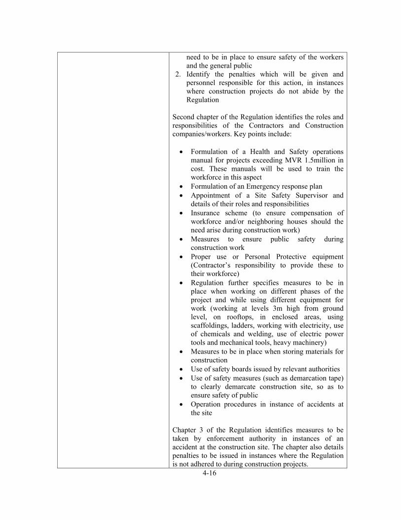
Second chapter of the Regulation identifies the roles and responsibilities of the Contractors and Construction companies/workers. Key points include:
Formulation of a Health and Safety operations manual for projects exceeding MVR 1.5million in cost. These manuals will be used to train the workforce in this aspect
Formulation of an Emergency response plan Appointment of a Site Safety Supervisor and
details of their roles and responsibilities Insurance scheme (to ensure compensation of
workforce and/or neighboring houses should the need arise during construction work)
Measures to ensure public safety during construction work
Proper use or Personal Protective equipment (Contractor’s responsibility to provide these to their workforce)
Regulation further specifies measures to be in place when working on different phases of the project and while using different equipment for work (working at levels 3m high from ground level, on rooftops, in enclosed areas, using scaffoldings, ladders, working with electricity, use of chemicals and welding, use of electric power tools and mechanical tools, heavy machinery)
Measures to be in place when storing materials for construction
Use of safety boards issued by relevant authorities Use of safety measures (such as demarcation tape)
to clearly demarcate construction site, so as to ensure safety of public
Operation procedures in instance of accidents at the site
Chapter 3 of the Regulation identifies measures to be taken by enforcement authority in instances of an accident at the construction site. The chapter also details penalties to be issued in instances where the Regulation is not adhered to during construction projects.

4-17
Regulation on fuel storage and use (2015/ R-160)
The objective of this regulation is to:
Decrease the number of accidents due to fuel usage and storage and protect the people and their belongings from such incidences
Raise awareness regarding protective measures which should be in place when using/storing fuel
Establish means which would enable all places which sell fuel (currently established and in the future) to do so under proper protective measures
The implementing agency for this regulation is the Ministry of Defense and National Security and enforcement of the regulation began on the day the regulation was published in the government gazette (12th August 2015).
All current establishments which use and store fuel have to abide by the regulation and existing establishments were given grace periods of 6 months and 1 year to modify their setups so as to meet the criteria outlined in the Regulation.
Future establishments should be set up as per the regulation, inclusive of firefighting and safety measures. Operation of new facilities can only commence once they have been checked and approved by the implementing agency (MNDF). Existing facilities (at time of implementation of regulation) which had not prior obtained permission from MNDF should also continue their operations after getting the required approval.
Appendix 6 of the Regulation states distance which should be left between the bund wall and adjacent residential areas (inclusive of road). These distances are based on the capacity of the facility.
The implementing agency has the authority to make inspections at the facilities once every 6 months and this will be done in the presence of the owner of the facility. During such inspections, the implementing authority will advise if any changes have to be brought to the facility. In such instances the facility will be checked again after been given a time period to make this change.
GMIZL Aanmu Gavaaidhu This Regulation details all measures and protocols to be followed by the different industrial projects being carried out and to be carried out at Thilafushi and Gulhifalhu. The Regulation further details fees to be charged for

4-18
different services as well as penalties for failing to abide by the Regulation. It looks at 9 main areas:
1. Buildings and construction 2. Plots and roads 3. Operation of land vehicles 4. Travel within Thilafushi and Gulhifalhu 5. Harbours and lagoon area 6. Items washed ashore / beached 7. Cleanliness and food handling 8. Storage and transfer of chemicals 9. Other matters
5-19
5 Project Description 5.1 Project Proponent
The proponent of the proposed project is Maldives Petroleum Links Pvt Ltd. The total
estimated cost of the project is USD 4.2 million.
5.2 The Project
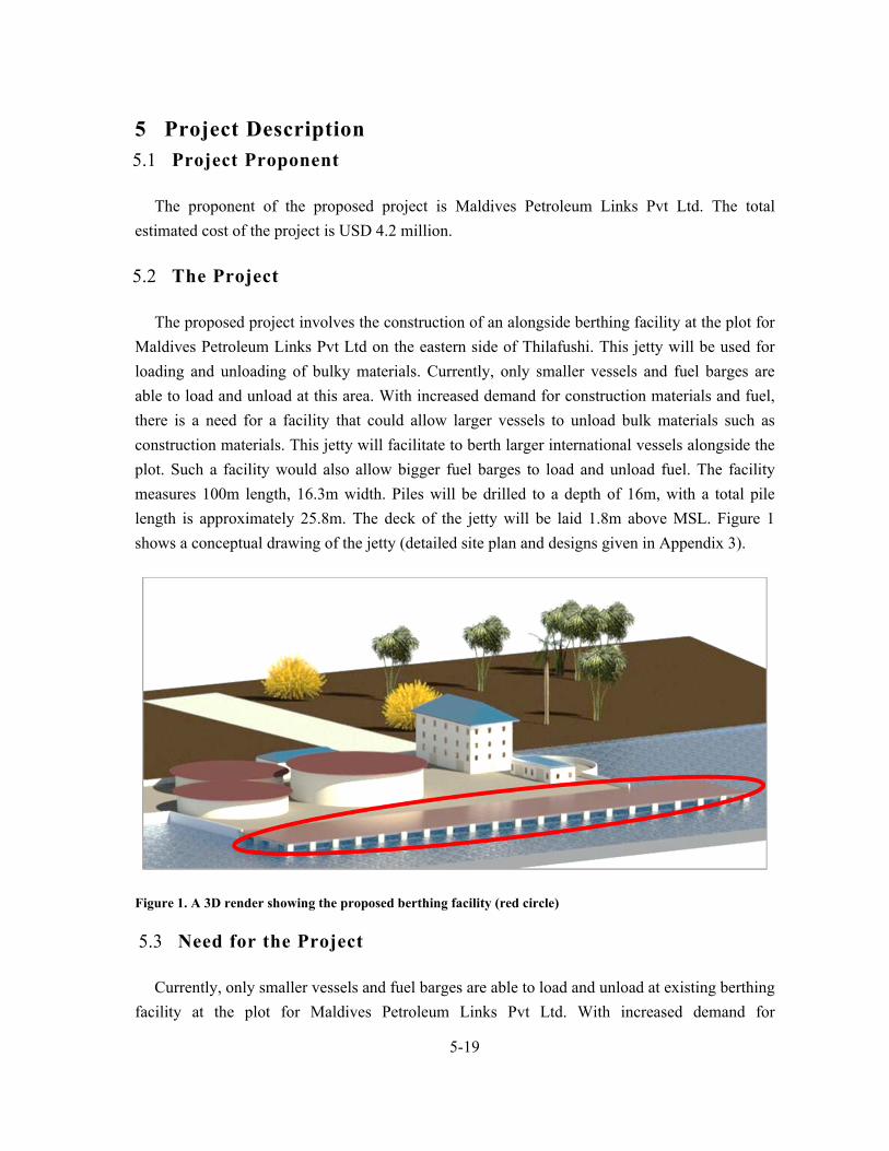
The proposed project involves the construction of an alongside berthing facility at the plot for
Maldives Petroleum Links Pvt Ltd on the eastern side of Thilafushi. This jetty will be used for
loading and unloading of bulky materials. Currently, only smaller vessels and fuel barges are
able to load and unload at this area. With increased demand for construction materials and fuel,
there is a need for a facility that could allow larger vessels to unload bulk materials such as
construction materials. This jetty will facilitate to berth larger international vessels alongside the
plot. Such a facility would also allow bigger fuel barges to load and unload fuel. The facility
measures 100m length, 16.3m width. Piles will be drilled to a depth of 16m, with a total pile
length is approximately 25.8m. The deck of the jetty will be laid 1.8m above MSL. Figure 1
shows a conceptual drawing of the jetty (detailed site plan and designs given in Appendix 3).
Figure 1. A 3D render showing the proposed berthing facility (red circle)
5.3 Need for the Project
Currently, only smaller vessels and fuel barges are able to load and unload at existing berthing
facility at the plot for Maldives Petroleum Links Pvt Ltd. With increased demand for

5-20
construction materials and fuel, there is a need for a facility that could allow larger vessels to
unload bulk materials such as construction materials. Furthermore, such a facility would allow
bigger fuel barges to load and unload fuel. Anticipated vessel call to the facility is 3 vessels of
length 100m (draft of 12m and DWT 20,000) each week.
5.4 Location and Extent of Site Boundaries
The proposed project will be carried out at the plot area for Maldives Petroleum Links Pvt Ltd
on the eastern edge of Thilafushi (Figure 2).
Figure 2. Proposed location for construction of alongside berthing facility (in red)
5.5 Construction phase and schedule for implementation
The proposed development is estimated to be completed within 11 months of work
commencement. Detailed schedule for implementation of these components is given in
Appendix 4. Key activities and estimated time periods are listed below:
Mobilization - 14 days
Piling works – 195 days
Concrete works – 110 days
Completion and handover – 2 days
5-21
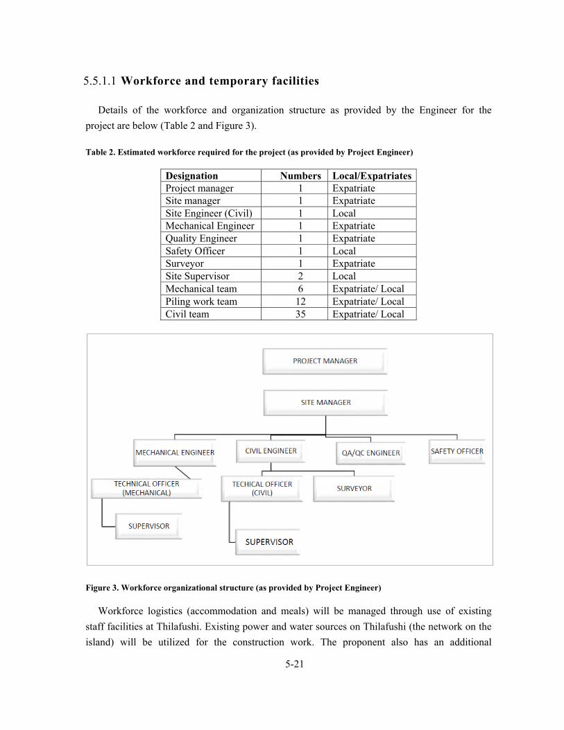
5.5.1.1 Workforce and temporary facilities
Details of the workforce and organization structure as provided by the Engineer for the
project are below (Table 2 and Figure 3).
Table 2. Estimated workforce required for the project (as provided by Project Engineer)
Designation Numbers Local/Expatriates Project manager 1 Expatriate Site manager 1 Expatriate Site Engineer (Civil) 1 Local Mechanical Engineer 1 Expatriate Quality Engineer 1 Expatriate Safety Officer 1 Local Surveyor 1 Expatriate Site Supervisor 2 Local Mechanical team 6 Expatriate/ Local Piling work team 12 Expatriate/ Local Civil team 35 Expatriate/ Local
Figure 3. Workforce organizational structure (as provided by Project Engineer)
Workforce logistics (accommodation and meals) will be managed through use of existing
staff facilities at Thilafushi. Existing power and water sources on Thilafushi (the network on the
island) will be utilized for the construction work. The proponent also has an additional

5-22
operational generator on site, with capacity of 150 KVA. This will be utilized should the need
for additional power source arise.
5.6 Major Inputs and Outputs
5.6.1 Access to site, mobilization and material unloading
Machinery and construction material will be mobilized to site on barges. Construction
materials will be stored at the temporary construction yard/storage area set up on site.
5.6.2 Project inputs and outputs
Major project inputs required for the project and their outputs are shown in Table 3 below.
These have been sourced from the Method Statement provided by the Client (also given in
Appendix 5).
Table 3. Major inputs required for the project and their outputs
Inputs Source Outputs Management 15mm thickness steel plates
Imported material. Contractor may purchase locally or import directly.
Steel casing around pile Contractor
Concrete (grade 30) Imported material. Contractor may purchase locally or import directly.
Pile construction Contractor
Bentonite (50kg bags)
Imported material. Contractor may purchase locally or import directly.
To stabilize unstable
subsoil conditions
Contractor
Resin bounded Plywood (varying thickness)
Steel bars and steel wire
Construction of pile caps, plinth beams and platform
5.6.2.1 Equipment
Details of main machinery and equipment required for the proposed work is given in
Table 4.

5-23
Table 4. List of machinery required for the project
Machinery Quantity Use at site Rotary drill rigs 1 Pile boring Rotary Kelly bar 1 Excavation of soil from bored holes Augers and drilling buckets Rock Auger 1 Drilling through rock strata Core Barrels Cross cutters Chisels Cleaning bucket 1 Removal of loose and remolded material High turbulence mixers and pool
Mixing and storage of bentonite (slurry)
Bentonite testing apparatus
Mud balance – density tests
Marsh cone – viscosity tests
Sand screen set ph paper
1 Testing of slurry
Submersible turbine pumps Flush out bentonite after drilling is completed
Tremie Pipe and concrete mixer
Concrete works of piles
Excavator Removal of spoils Wheel barrows
5.7 Construction Methodology
5.7.1 Design of berthing facility
The alongside berthing facility has a length of 100m and width of 16.36m. The facility will be
constructed on total of 84 concrete piles (21 piles along the length and 4 along the width) placed
at a distance of 4.92m between two piles.
5.7.2 Workmanship
5.7.2.1 Pile Construction
Construction method given here is based on the Method Statement provided by the Client,
which is also given in Appendix 5 of this report.

5-24
Prior to Commencement of Work, site inspections will be held to identify the site condition.
Soil condition will be assessed with available boring soil tests, N-value measurement and other
appropriate testing done by the Contractor.
The pile boring operations will be carried out using the rotary drill rigs, specifications of
which depends on the diameter, depth, and soil condition and construction method. As specified
above a total of 84 Piles are designed for construction, each with a diameter of 600 mm and 5.0
m center to center intervals. The boreholes shall be stabilized with a temporary steel casing using
15mm thickness steel plates. The length of the casing will be determined from the actual soil
condition encountered on site.
Bentonite shall be used for unstable subsoil condition and for piles equal and more than 1800
mm diameter.
5.7.2.2 Setting out
The location of permanent bored piles shall be set out by the contractor’s surveyor based on
approved setting out drawings from consultant and control points at site. Each individually
surveyed pile position shall be protected from disturbance prior to commencement of boring
works. Two reference points will be installed equidistant at not less than 2.0m from the pile
center location. A pilot hole of about 3 - 6 meter deep shall be drilled at the pile location and
checked for alignment and eccentricity.
5.7.2.3 Drilling
Once the pile locations have been set by the surveyor, temporary casing will be set in
position, length of which will be determined by ground conditions. Excavation of the soil inside
the casing/bored holes will be carried out using the Rotary Kelly bar and the auger or bucket
method. The drilling process will be continued to the designed founding depth or to the
commencement of rock head level by using augers and drilling buckets. As per drawings given
by the proponent, drilling depth is 16m and total pile length is approximately 25.8m.
For drilling through rock, rock drilling tools shall be applied. This shall include rock auger,
core barrels, (round shank, roller bit) cross cutters and where necessary, chisels. The final toe
level of the pile shall be verified and a detailed record of all encountered ground conditions
together with the associated times and type of equipment and materials used will be recorded in
the ‘Pile Bore Log’.

5-25
Upon reaching the final depth, loose and remolded material and debris will be removed using
‘cleaning bucket’. The cleaning bucket is a specially design flat bottom bucket which will pick
up all the loose material at the bottom of the hole. The base of the hole shall be checked by the
measuring the depth of the base.
Bentonite, mixed by high turbulence mixers on site, will be used as a drilling fluid to stabilize
the bored hole. During the boring process, the bentonite slurry is kept as high as possible within
the casing and well above the existing ground water. Upon completion of boring, the bottom of
the bored hole is thoroughly cleaned with the cleaning bucket prior to recycling of the bentonite.
A submersible turbine pump attached to the tremie pipe is lowered to the bottom of the bored
hole. The bentonite, loaded with soil particles in suspension, is drawn off from the bottom of the
bored hole and recycled through a Caviem or equivalent recycling unit. The process is continued
until the bentonite arriving from the base of bored hole had been flush out.
5.7.2.4 Installation of steel cage
The reinforcement cage will be fabricated in lay-down sections. The length, type and size of
the steel cage will be according to contract drawings and specifications. The cages will be
provided with stiffening rings and other accessories to enable handling, lifting and installation
without permanent deformations. Cages will be installed into the bored hole using a service
crane of the required lifting capacity. Concrete spacers wired to the cage shall provide lateral
support and ensure adequate concrete cover. Spacers shall be placed at 3 equal levels of each
12m cage with 3 spacers at each level. Number of spacers will be increased if the diameter of
bored pile is more than 200cm.
5.7.2.5 Concrete work
Concrete work of all piles will then be carried out using the tremie method. Concrete of
higher slump (=175mm+25mm) unless otherwise specified, shall be used for ‘tremie’ method.
The self-compacting mixed concrete will be discharged through a tremie pipe, which is lowered
centrally to the bottom of the bored hole prior to filling it with concrete.
All testing and sampling of the concrete shall be carried out as instructed by the Engineer or
Engineer’s representative. For a continuous assurance of concrete quality and integrity, concrete
will be poured to minimum 0.6m above the theoretical cut-off level.
All completed piles shall be temporarily barricaded and backfilled to ground level with a
suitable material the next day. Spoil from piles will be cleared from the boring locations by

5-26
means of an excavator as boring proceeds. Depending on the volume of spoil excavated, it will
be removed to stockpile area or spoil pit, for drying before being loaded and removed off-site.
5.7.2.6 Construction of pile caps and plinth beams
Plywood Phonic
Resin bounded plywood shall be used as it is completely waterproof and does not laminate as
does ordinary plywood. Plywood panels shall be formed with timber and nailed with short, thin
nails at 150 to 225mm centers. 6 or 10mm thick plywood shall be given a solid a backing nailed
at 100 to 150mm spacing along the four edges and with at least one nail every 0.1 square meter
throughout the surface. The edges of sheets shall be tacked to the same backing board to ensure
the production of a smooth joint.
10 and 16mm thick plywood shall be nailed to a skeleton backing of dressed timber before
fixing to the studding. 19mm thick plywood shall be nailed direct to studs at a maximum
recommended spacing of 450mm. For spacing greater than 450mm skeleton backing of
appropriate design shall be used.
Steel
The reinforcement shall be from an approved manufacturer. All the corrosions will be wire
brushed prior to the use. Only reinforcements with sufficient strength shall be use.
Reinforcements shall be cut and /or bend correctly and accordingly to the requirements following
BS 4466 standards. Preferably bars of full length will be used. Binding shall be done with two
standards of annealed steel wire 0.9 -1.6mm thickness. Proper cover blocks or spacer will be use
prior to the concreting.
Formwork
All formworks are fabricated with Plywood sheets in varied thickness as per the location.
Plywood sheets are supported with 2” x 4” Timber as required. GI Pipes, acrow prop will be
supported to formwork. Formwork will be arranged for Pile Caps, Tie Beam and deck slab by
using 12 – 15mm thick plywood sheets as per shown details.
Construction of Pile Caps & Plinth Beams will commence after completion and testing of
piles. Pile caps will be cast along with the Tie Beams and Deck Slab.

5-27
5.7.2.7 Construction of Platform
Formwork will be arranged with 12mm thick Plywood sheet with the circular beam, cross
beams and circular platform. Platform formwork will be connected with wall shaft formwork set
under platform.
Pouring concrete in Platforms
Concrete for each level of platform and beams will be poured with bottom level of wall shaft.
The concrete shall be transported from the mixer with the possible delay in liquid tight
containers or barrows and by methods which prevent the segregation or loss of ingredients.
Slump loss in transit shall not exceed 25mm. Maximum drop shall be maintained up to a
maximum level of 2.4 m. Required tests such as slump tests and cube test will be done prior to
the concreting.
Shuttering shall be cleaned of all shavings, saw dust, pieces of wood, or other foreign material
using air and water pressure hoses. All accumulation of water or debris shall be flushed out
through the holes or opening provided for the purpose. These holes shall be neatly plugged
before concreting.
The full depth of fresh concrete shall be completed without damaging adjacent partly
hardened concrete. Concrete shall be considered as properly compacted when the air bubbles
cease to appear on the upper surface and mortar fills the spaces between the coarse aggregate and
begins to cream up to form an even surface.
When this condition has been attained, the vibrator shall be stopped if using vibrating tables
or external vibrators, while needle vibrators shall be withdrawn slowly so as to prevent formation
of loose pockets. In case both internal and external vibrators are being used, the internal vibrators
shall first be withdrawn slowly after which the external vibrators shall be stopped so that no
loose pocket is left in the body of the concrete. The specific instructions of the makers of the
particular type of vibrator used shall be strictly complied with. Over vibration shall be avoided.
Shaking of reinforcement for the purpose of compaction shall be resorted to Likewise; all
precautions shall be taken to prevent displacement of the reinforcement during the placing and
compaction of concrete.
5.7.2.8 Curing
After the concrete has begun to harden i.e. about 1 to 2 hours after its laying, it shall be
protected from quick drying with moist gunny bags, sand or any other suitable material. After 24

5-28
hours of laying of concrete, the surface shall be cured by flooding with water of minimum 25mm
depth, or by covering with wet absorbent materials, e.g. damp hessian or jute, coconut or straw
matting, or a layer of sand about 50mm thick. The curing shall be done for a minimum period of
7 days.
5.7.3 Engineering design with load calculation details
The loads on the berthing structure arises from a combination of deadloads, live loads, wind
loads, seismic loads, berthing forces and mooring forces.
The dead loads are mainly the vertical loads caused by the self-weight of the deck, piles and
the super imposed loads from handling equipment. The total dead load of the structure was found
to be approximately 3742 tons. The live loads are the temporary loads acting on the structure.
Based on IRC class A, the live loading was assumed to be 1.5 tons per square meter.
Wind loads are generally considered a horizontal load and based on IS: 875, Code of practice
for wind forces, the wind load was calculated as 841 N per square meter.
The seismic load considers the vertical forces that will act during an earthquake and was
calculated based on IS: 1893: Recommendations for earthquake resistant design of structures and
was found to be 230kN at the structure base.
The berthing forces due to the impact of vessels were calculated by assuming a design vessel
with length L= 100 MTS, Draft D= 12m and dead weight tonnage of 20,000 tons. The berthing
force was calculated as 34 tonnes.
The vessel mooring loads arises due to wind forces and current forces. The mooring force due
to current forces was calculated according to IS: 4651 (III) Cl.5.3.4, linepull for maximum vessel
of 20000 DWT is 600 kN and was applied over the deck slab. The mooring force due to wind
are due to the wind forces on exposed area on the broad side of the vessel in light condition. As
per IS 4651: part- III clause no. 5.3.2 this mooring force was calculated as 38 tons.
In addition, the wave loading acting over piles were 2.805 kN for normal wave while 8.5 kN
for extreme wave case. Wave force was applied as a point load at mean sea level on all the piles
in both the directions. Furthermore, to consider the effects of thermal expansion, joints were
provided at 150m to reduce temperature stresses.

5-29
5.7.4 History of site and reasons why previous berthing facility
collapsed and how this is addressed in current design
An alongside berthing facility at the plot was first constructed in 2011, following reclamation
of land area at the plot. The berthing facility was constructed to cater for berthing of larger
vessels, while the area was reclaimed as a storage area. However, the port structure was damaged
due to slope failure, which in turn lead to structural failure of the berth. The entire structure of
the berthing facility sank to the bottom of the reef slope. As a result of this, the fuel farm under
construction at the sea front at the time was left unprotected and erosion of the reclaimed land at
the time had the potential to compromise the foundation structure of the tanks, which were
almost complete and ready for loading. The proponent then proposed to carry out sheet piling
works for protection of shoreline (construction of a retaining structure) at the damaged berthing
area. The new protection system was placed with a 12m offset from the failure line to allow for
future developments to be designed separately. The sheet pile system was designed to contain the
soil on the seaward side of the tank foundation and the retaining structure was not designed for
loading and unloading at the area. The offset of 12m from failure line and the design of berthing
facility to facilitate alongside berthing by larger vessels (through proper load calculations, based
on soil report) will address the issues encountered previously, which resulted in collapse of
previous berthing facility.
5.7.5 Project management
Project site office will be setup at the plot to manage the construction works. Supervision
engineer will be assigned to oversee construction work.
5.7.6 Waste management
All forms of waste generated would be collected and disposed through WAMCO’s waste
management services established at Thilafushi.
5.7.6.1 Emergency contingency plan in case of work accidents,
contaminant spills
Worker safety and provision for first aid kits will be included in the contract with project
contractor. In addition to this, workers will be sent to Male’ for further treatment (contractor
responsibility). All machinery will be maintained accordingly to ensure fuel or engine oil does
not leak.

5-30
The method statement provided by the engineers gives a detailed list of safety measures,
which are shown below (as sourced directly from the Method Statement):
Signboards will be erected and maintained continuously in excavated areas.
Adequate lighting, warning signals and luminous barricades will be provided throughout
the night until backfilling is completed.
During the continuation of the whole working period, officers with relevant experiences
will be dispatched for 24-hour stand by to cope with emergency situations. First- aid kits
and Emergency Telephone Numbers will be kept at site officer all the time. In case of
emergency, Special Emergency Team, Safely Officer and Site Manager will be informed
and brought to the site to handle the problem promptly.
Plant, machinery, equipment and hand tools
General provisions
Plant, machinery and equipment, including hand tools, both manual and power-driven,
shall:
a) Be of good design and construction, taking into account, as far as possible, health
and safety and ergonomic principles
b) Be maintained in good working order
c) Be used only for work for which they have been designed unless a use outside the
initial design purpose has been assessed by a competent person who has concluded
that such use is safe;
d) Be operated only by workers who have been authorized and given appropriate
training:
e) Be provided with protective guards, shields, or other devices as required by national
laws or regulations.
Adequate instructions for safe use shall be provided where appropriate by the
manufacturer or the employer, in a form understood by the user
As far as practicable, safe operating procedures shall be established and used for all plant,
machinery and equipment
Operators of plant, machinery and equipment shall not be distracted while work is in
progress.
Plant machinery and equipment shall be switched off when not in use and isolated before
any major adjustment, cleaning or maintenance is done

5-31
Where trailing cables or hose pipes are used they shall be kept as short as practicable and
not allowed to create a safety hazard.
All dangerous moving parts of machinery and equipment shall be enclosed or adequately
guarded in accordance with national laws and regulations.
Every power-driven machine and equipment shall be provided with adequate means,
immediately accessible and readily identifiable to the operator, of stopping it quickly and
presenting it from being started again inadvertently.
The machines or equipment shall be so designed or fitted with a device that the maximum
safe speeds, which shall be indicated on it. Is not exceeded; if the speed of the machine is
variable, it shall only be possible to start it at the lowest speed appropriate.
Operators of plant, machinery, equipment and tools shall be provided with personal
protective equipment including, where necessary, Suitable hearing protection.
Hand tools
Hand tools and implements shall be tempered, dressed and repaired by competent persons.
The cutting edges of cutting tools shall be kept
Heads of hammers and other shock tools shall be dressed or ground to a suitable radius on
the edge as soon as they begin to mushroom or crack.
When not in use and while being carried or transported sharp tools shall be kept in
sheaths, shields, chests or other suitable containers
Only insulated or non-conducting tools shall be used on or near live electrical installations
if there is any risk of electrical shock
Only non-sparking tools shall be used near or in the presence of flammable or explosive
dusts or vapors.
Electrical tools
Portable electrical tools shall generally be used on reduced voltage to avoid as far as
possible the risk of a lethal shock.
All electrical tools shall be earthed unless they are “all insulated” or “double insulated”
tools which do not require an earth. Earthlings shall be incorporated in metallic cases and
as a safeguard against damaged cables where wires enter the tool.
All electrical tools shall receive inspection and maintenance on a regular basis by a
competent electrician, and complete records kept.

5-32
Woodworking machines
Shavings, sawdust, Etc., shall not be removed by hand from woodworking machines or in
their vicinity while the machines are working
On hand saws all the blades, except the operating portion, shall be enclosed. Band wheels
shall be enclosed with stout guards
Band saws shall be provided with automatic tension regulators.
Planning machines shall be provided with bridge guards covering the full length and
breadth of the cutting block and easily adjustable in both horizontal and vertical
directions.
Thickness machines shall be provided with sectional feed rollers or a kick-back preventer
which shall be kept as free as possible.
Woodworking machines shall be properly spaced to avoid accidental injury when handling
large boards or long planks
Where provided. Chip and sawdust extraction s stems shall be maintained in efficient
working order
Mechanical feeding devices shall be used whenever practicable.
All cutters and saw blades shall be enclosed as far as practicable
Circular saws shall be provided with strong, rigid and easily adjustable guards for the saw
blades and with riving knives of suitable design matched to the saw blade in use. The
width of the opening in the table for the saw blade shall be as small as practicable
Portable circular saws shall be so designed that when the blade is running idle it is
automatically covered.
Concrete work equipment
Concrete mixers shall be protected by side railings to prevent workers from passing under
the skip while it is raised.
Hoppers into which a person could fall, and revolving blades of trough or batch-type
mixers, shall be adequately guarded by grating.
In addition to the operating brake, skips of concrete mixers shall be provided with a device
or devices by which they can be securely blocked when raised.
While the drum of a concrete mixer is being cleaned, adequate precautions shall be taken
to protect the workers inside by locking switches open, removing fuses or otherwise
cutting off the power.
Concrete buckets for use with cranes and aerial cableways shall be free as far as
practicable from projections from which accumulations of concrete could fall.

5-33
Loaded concrete buckets shall be guided into position by appropriate means.
Concrete buckets positioned by crane or aerial cableways shall be suspended by safety
hooks.
When concrete is being tipped from buckets, workers shall keep out of range of any kick-
back due to concrete sticking to the bucket.
Concrete bucket towers and masts with pouring gutters or conveyor belts shall:
a) Be erected by competent persons;
b) Be inspected daily.
The winch for hoisting the bucket shall be so placed that the operator can see the filling,
Hoisting, emptying
Where practicable, be provided with an adequate means indicating its position.
Guides for the bucket shall be correctly aligned and so maintained as to prevent the bucket
from jamming in the tower.
Scaffolding carrying a pipe for pumped concrete shall be strong enough to support the
pipe when filled and all the workers who may be on the scaffold at the same time, with a
safety factor of at least 4.
Pipes for carrying pumped concrete shall:
a) Be securely anchored at the ends and at curves:
b) Be provided near the top with air release valves;
c) Be securely attached to the pump nozzle by a bolted collar or equivalent means.
6-34
6 Methodology
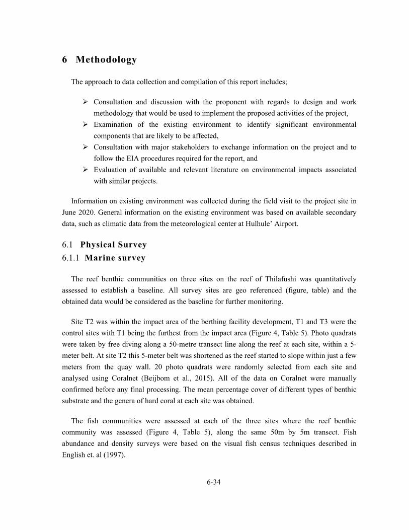
The approach to data collection and compilation of this report includes;
Consultation and discussion with the proponent with regards to design and work
methodology that would be used to implement the proposed activities of the project,
Examination of the existing environment to identify significant environmental
components that are likely to be affected,
Consultation with major stakeholders to exchange information on the project and to
follow the EIA procedures required for the report, and
Evaluation of available and relevant literature on environmental impacts associated
with similar projects.
Information on existing environment was collected during the field visit to the project site in
June 2020. General information on the existing environment was based on available secondary
data, such as climatic data from the meteorological center at Hulhule’ Airport.
6.1 Physical Survey
6.1.1 Marine survey
The reef benthic communities on three sites on the reef of Thilafushi was quantitatively
assessed to establish a baseline. All survey sites are geo referenced (figure, table) and the
obtained data would be considered as the baseline for further monitoring.
Site T2 was within the impact area of the berthing facility development, T1 and T3 were the
control sites with T1 being the furthest from the impact area (Figure 4, Table 5). Photo quadrats
were taken by free diving along a 50-metre transect line along the reef at each site, within a 5-
meter belt. At site T2 this 5-meter belt was shortened as the reef started to slope within just a few
meters from the quay wall. 20 photo quadrats were randomly selected from each site and
analysed using Coralnet (Beijbom et al., 2015). All of the data on Coralnet were manually
confirmed before any final processing. The mean percentage cover of different types of benthic
substrate and the genera of hard coral at each site was obtained.
The fish communities were assessed at each of the three sites where the reef benthic
community was assessed (Figure 4, Table 5), along the same 50m by 5m transect. Fish
abundance and density surveys were based on the visual fish census techniques described in
English et. al (1997).

6-35
Figure 4. Reef survey locations (T1 – T3) and seawater sampling locations (SW1 and SW2) at Thilafushi
Table 5. Geocoordinates of Reef survey locations and seawater sampling locations at Thilafushi
Name Latitude Longitude Survey Type
T1 4°11'16.57"N 73°26'1.86"E Quantitative Reef Survey
T2/SW1 4°10'57.82"N 73°27'4.76"E Quantitative Reef Survey/Seawater Quality Analysis
T3/SW2 4°10'36.30"N 73°27'7.97"E Quantitative Reef Survey/Seawater Quality Analysis
6.1.2 Sea Water Quality Analysis
Seawater quality was tested in-situ using a Hanna HI9829 multi-probe water testing meter (to
test the physical parameters) at the two sites SW1 and SW2 (Figure 4, Table 5). Multiple
readings were taken with the Hanna HI9829 and the results were averaged. Water samples were
also collected from these two sites and sent to the MWSC Water Quality Assurance Laboratory.
The water quality data from SW2 would be considered as the control and SW1 is within the
project impact area. The data obtained from the two sites would be considered as the baseline for
further monitoring.
6.1.3 Tide and wave survey
Site specific tide and wave analysis from archived data from June 2011 were used to describe
the tide and wave climate around Thilafushi. Wave data at Thilafushi was measured for 9 days at
southern side of reef. Location of RBR data logger is shown in Figure 5.

6-36
Figure 5. Location where the RBR data logger was deployed to study the wave characteristics
6.1.4 Bathymetry
In order to assess the baseline conditions of the proposed project location, bathymetric survey
of the project location was carried out in June 2020. The bathymetric survey was carried out as
acoustic depth (z) measurements together with DGPS position (x,y) fixings (Topcon Gr5 DGPS).
Acoustic depth measurement systems measure the elapsed time that an acoustic pulse takes to
travel from a generating transducer to the waterway bottom and back. In areas where bottom
topography is very uneven, additional lines were run to capture the bottom topography, while the
rest of the area was done at 50m transects. Existing Permanent Survey Marks (PSMs) at TIZ is
used as level control for the survey.
Wave gauge location 4 10.750N, 73 26.495E0 0

7-37
7 Existing environment 7.1 Geographic location of Thilafushi
Thilafushi is located at the southern periphery of North Male’ Atoll. The island lies at
coordinates on 4°11'2.87" N and 73°26'26.80" E, approximately 5.88 km to the west of Capital
Male’ City (Figure 6). Gulhifalhu, which is also a developing industrial island, is located about
0.59 km to the east of Thilafushi, separated by a narrow channel.
Figure 6. Location of the Thilafushi at North Male’ Atoll (A, yellow highlight) and satellite image of Thilafushi (B), Project location (C, yellow highlight)
7.2 Climate
7.2.1 Wind climate
Wind climate in the Maldives is dominated by the Indian Ocean monsoon climate, with the
South West (SW) monsoon and North East (NE) monsoon. The Indian monsoon system is one of
the major climate systems of the world, impacting large portions of both Africa and Asia
(Overpeck et, al., 1996). The monsoon climate is driven by the atmospheric pressure differences
that arise as a result of rapid warming or cooling of the Tibetan Plateau relative to the Indian
Ocean. During the summer of northern hemisphere the Tibetan Plateau warms rapidly relative to
the Indian Ocean which results in an atmospheric pressure gradient (Low pressure over Asia and

7-38
high pressure over the Indian Ocean) between the Asian landmass and the Indian ocean, which
drives the prevailing wind from south to westerly directions. The period during which prevailing
winds are from south to westerly direction is known as the SW monsoon. In the winter of
northern hemisphere the continent cools relative to the ocean. This reverses the pressure gradient
(low pressure over the Indian Ocean high pressure over the Asian landmass) and the prevailing
winds become northeasterly. The period during which prevailing winds are from northeasterly
directions is known as NE monsoon. The transitions from NE to SW monsoon and vice versa
are distinctly different from SW or NE monsoon. During these transition periods the wind
becomes more variable.
The SW monsoon lasts between May and September while the NE monsoon lasts between
December and February. The period between March and April is the transition period from the
NE monsoon to SW monsoon known locally as the Hulhangu Halha, while the transition period
from SW monsoon to NE monsoon is known as Iruvai Halha. Iruvai halha lasts from October to
November. The SW monsoon is generally rough and wetter than the NE monsoon. Storms and
gales are infrequent in this part of the world and cyclones do not reach as far south as the
Maldivian archipelago (Ministry of Construction and Public Works, 1999).
Analysis of wind climate was done using mean and maximum wind data from Hulhule’
meteorological center, which is the closest meteorological station to project site. Mean wind data
were available for a period of 34 years (from January 1985 to March 2019) whereas maximum
wind speed data were available for 11 years (from January 2008 to March 2019). In order to
understand the dominant wind directions, wind rose diagrams were analyzed for the whole
period as well as for each month using wind speed and direction.
Looking at the frequency plot data and wind rose plots, it was observed that the mean wind
speed had gone as high as 36kn towards the WNW direction. But the probability of occurrence
was very low (only 0.02% of the times). In general, the strongest winds occur from WSW, W
and WNW directions. Winds from the south and SE as well as north were less prevalent and with
comparatively low speeds. Majority of the times (about 12 to 19% of the times), winds occur at a
speed of 4 to 14kn which is generally known as light to moderate breeze. Wind speeds above
18kn were a rare occurrence, occurring about 1.67 to 0.02% of the times (Figure 7).
With respect to maximum wind speeds, visual inspection of the wind rose plot coincides with
that of the mean wind speeds. Approximately 1.46% of the times, wind speeds had gone as high
as > 40kn at this region. The highest recorded maximum wind speed for the region was 54kn in
the month of July during the data collection period. Winds higher that 24kn were frequent,
occurring about 24% of the times. The most common maximum wind speed is between 12-16kn.

7-39
Wind rose plots for both maximum and mean wind speeds show that winds from the western
quadrant are dominant (about 23% of the times) (Figure 7).
Figure 7. Wind rose plot for Hulhule’ Meteorological station, based on mean daily wind data for the period of January 1998 to March 2019 (left) and maximum daily wind data (right) for the period of January 2008 to March 2019
With regards to mean wind speeds per month, results from this analysis were contradictory
with the traditionally defined monsoonal months. It is evident from Figure 8 that the SW
monsoon lasts from April to October whereas it is traditionally defined that the SW monsoon of
the Maldives commences in May and ends in September and the months March to April and
October to November are transition periods. But clearly, during April, transition from NE to SW
monsoon had already occurred as the winds were predominantly coming from the west, and NE
winds were almost zero to negligible. Likewise, in October, the transition from SW to NE has
not commenced yet as the winds was not only predominantly coming from the westerly direction
but also at a strong speed. March and November can, however, be taken as the transition periods
(Figure 8, Table 6).
Additionally, during the SW monsoon, winds are known to occur dominantly from the SW
direction, however the results indicate that the strongest and most dominant winds occur from
the west and the second most dominant frequency fluctuates between WSW and WNW
directions. As for the NE monsoon, winds predominantly occur form the NE direction, agreeing
with the traditional definition (Figure 8).
With reference to monthly maximum wind speeds, unlike the mean monthly wind speeds,
only one transition period was observed from the wind rose analysis. Wind direction changes
abruptly from NE to W on April and a clear transition period from W to NE monsoon is
0
45
90
135
180
225
270
315
<=2
>2 - 4
>4 - 6
>6 - 8
>8 - 10
>10 - 12
>12 - 14
>14 - 16
>16 - 18
>18 - 20
>20 - 22
>22 - 24
>24 - 26
>26 - 28
>28 - 30
>30 - 32
>32 - 34
>34 - 36
>36 - 38
>38 - 40
>40
0% 4% 8% 12% 16% 20% 24%

7-40
observed in November which extends to December as well. The highest maximum wind speeds
occur during July and January to March are generally the calmer months (Figure 9).
Table 6. The traditionally defined seasons experienced in Maldives compared with the current analysis of seasonal winds per month
Month Traditionally defined seasons Seasons as per our analysis
December
NE monsoon NE monsoon January
February
March Transition period 1
Transition period 1
April
Winds predominantly from
the west
May
SW monsoon June
July
September
October Transition period 2
November Transition period 2

7-41
Figure 8. Monthly wind rose plots for Hulhule’ Meteorological station, based on mean daily wind data for the period of January 1995 to March 2019.
0
45
90
135
180
225
270
315
January
0% 10% 20% 30% 40% 50%
0
45
90
135
180
225
270
315
February
0% 10% 20% 30% 40%
0
45
90
135
180
225
270
315
March
0% 4% 8% 12% 16% 20% 24%
0
45
90
135
180
225
270
315
0% 4% 8% 12% 16% 20% 24% 28% 32%
April0
45
90
135
180
225
270
315
0% 10% 20% 30% 40%
May0
45
90
135
180
225
270
315
0% 8% 16% 24% 32% 40%
June
0
45
90
135
180
225
270
315
0% 8% 16% 24% 32%
July0
45
90
135
180
225
270
315
0% 4% 8% 12% 16% 20% 24% 28% 32%
August0
45
90
135
180
225
270
315
Legend
<=2
>2 - 4
>4 - 6
>6 - 8
>8 - 10
>10 - 12
>12 - 14
>14 - 16
>16 - 18
>18 - 20
>20 - 22
>22 - 24
>24 - 26
>26 - 28
>28 - 30
>30 - 32
>32 - 34
>34 - 36
>36 - 38
>38 - 40
>40
0% 8% 16% 24% 32% 40%
September
0
45
90
135
180
225
270
315
0% 10% 20% 30% 40%
October0
45
90
135
180
225
270
315
0% 4% 8% 12% 16% 20% 24% 28%
November0
45
90
135
180
225
270
315
0% 8% 16% 24% 32% 40%
December

7-42
Figure 9. Monthly wind rose plots for Hulhule’ Meteorological station, based on maximum daily wind data for the period of January 2008 to March 2019
7.3 Temperature
Being an equatorial country, temperature of the Maldives does not fluctuate much throughout
the year and remains almost the same. Temperature data recorded by the meteorological station
0
45
90
135
180
225
270
315
0% 10% 20% 30% 40%
January0
45
90
135
180
225
270
315
0% 8% 16% 24% 32% 40%
February0
45
90
135
180
225
270
315
0% 4% 8% 12% 16% 20% 24%
March
0
45
90
135
180
225
270
315
0% 4% 8% 12% 16% 20% 24% 28%
April0
45
90
135
180
225
270
315
0% 8% 16% 24% 32% 40%
May0
45
90
135
180
225
270
315
0% 8% 16% 24% 32%
June
0
45
90
135
180
225
270
315
0% 8% 16% 24% 32% 40%
July0
45
90
135
180
225
270
315
0% 8% 16% 24% 32%
August0
45
90
135
180
225
270
315
<=2
>2 - 4
>4 - 6
>6 - 8
>8 - 10
>10 - 12
>12 - 14
>14 - 16
>16 - 18
>18 - 20
>20 - 22
>22 - 24
>24 - 26
>26 - 28
>28 - 30
>30 - 32
>32 - 34
>34 - 36
>36 - 38
>38 - 40
>40
0% 8% 16% 24% 32% 40%
September
0
45
90
135
180
225
270
315
0% 8% 16% 24% 32% 40%
October0
45
90
135
180
225
270
315
0% 4% 8% 12% 16% 20%
November0
45
90
135
180
225
270
315
0% 4% 8% 12% 16% 20% 24%
December

7-43
at Hulhule’ for the period January 2008 to December 2019 were used to analyze the temperature
pattern in the region. Figure 10 shows the minimum, maximum and mean monthly temperatures
for Thilafushi region as per the data recorded by the station for the given period. As evident from
the figure, period between March to July recorded the highest temperature at this region, April
being the hottest month with an average temperature of 29.81˚C. The lowest temperatures were
recorded for the months December and January (28.33˚C).
Looking at the mean maximum and minimum temperature records for the region, the highest
maximum temperature recorded was 33.9˚C for April 2016 and the lowest minimum temperature
recorded was 22.20˚C for January 2018. Daily temperatures range from 31.1˚C during daytime
to 26.3˚C during nighttime on average. Mean maximum and minimum temperature records
follow the same trend as the mean monthly temperatures (Figure 10).
Figure 10. Minimum, maximum and mean monthly temperatures for Thilafushi region (Data recorded for period between January 2008 and December 2019)
7.3.1 Rainfall characteristics
The rainfall pattern at Thilafushi region and for the rest of the Maldives is driven by the
monsoonal cycles. Rainfall data for the period between January 2008 and December 2019 from
the meteorological station in Hulhule’ were used to study the rainfall patterns at Thilafushi
(Figure 11).
The average annual rainfall for Thilafushi was found to be 8.57mm and the heaviest rainfall
recorded over the 10 year period was 143.2mm. Monthly mean rainfall shows that the driest
months are January to March and the wettest months are May, August and October.
25
26
27
28
29
30
31
32
Jan
Feb
Mar
Apr
May Jun
Jul
Aug Sep Oct
Nov
Dec
Mea
n m
onth
ly T
emp
(˚C
)
max min mean

7-44
Figure 11. Mean monthly rainfall for Thilafushi region (Data recorded for period between January 2008 and December 2019)
7.4 Hydrography/Hydrodynamics
7.4.1 Tide and water levels
Tides in the Maldives are usually characterized as a mixed tide. It contains two main cycles
(diurnal and semi-diurnal tides) per day. Harmonic analysis of the tides represents the period of
oscillation of the celestial forcing that gives rise to the respective harmonic.
As earlier mentioned, tide data is from archived data from 2011. Tide at Thilafushi was
measured for 9 days during the field visit to the island (in 2011). Tide data was collected using a
tide gauge deployed in the lagoon on the southern side of the island. Tidal analysis demonstrated
the mixed tidal nature and was used to establish a mean sea-level for the benchmarks established
on the island. Figure 12 shows the observed tide and the predicated tide for the duration of the
field visit. A reasonable correlation of 0.61 was observed between the measured tide and the
predicted tide indicating that the measured sea level data could be used with high confidence for
any designing aspect.
0
2
4
6
8
10
12
14
Jan
Feb
Mar
Apr
May Jun
Jul
Aug Sep Oct
Nov
Dec
Mea
n m
onth
ly r
ain
fall
(mm
)

7-45
Figure 12. Tide measured by the tide gauge and the superimposed predicted tide
7.4.2 Harmonic analysis of the tide
Tidal motion can be represented as a sum of series of several harmonics which is known as
the tidal constituents. The harmonic analysis assumes that the tide at any location comprise of
multiple tidal constituents. There are several tidal constituents of which the most significant are
formed by the gravitational attraction between the earth, moon and the sun. Table 7 shows the
principle tidal constituents and their respective period of occurrences. The subscripts 1 and 2
represent the types diurnal and semi-diurnal respectively. Of these constituents, K1, O1, P1, Q1,
M2, N2, S2, and K2 composes a significant part of a tidal signal.
Table 7. Principle tidal constituents (Defant, 1961)
Name Constituent Period (solar hr)
Principal lunar M2 12.42
Principal solar S2 12
Larger lunar elliptic N2 12.66
Luni-solar semidiurnal K2 11.97
Larger solar elliptic T2 12.01
Smaller solar elliptic L2 12.19
Lunar elliptic second order 2N2 12.91
Larger lunar evectional ν2 12.63
Smaller lunar evectional λ2 12.22
Variational μ2 12.87
Luni-solar diurnal K1 23.93
Principal lunar diurnal O1 25.82
Principal solar diurnal P1 24.07
Larger lunar elliptic Q1 26.87
R = 0.61
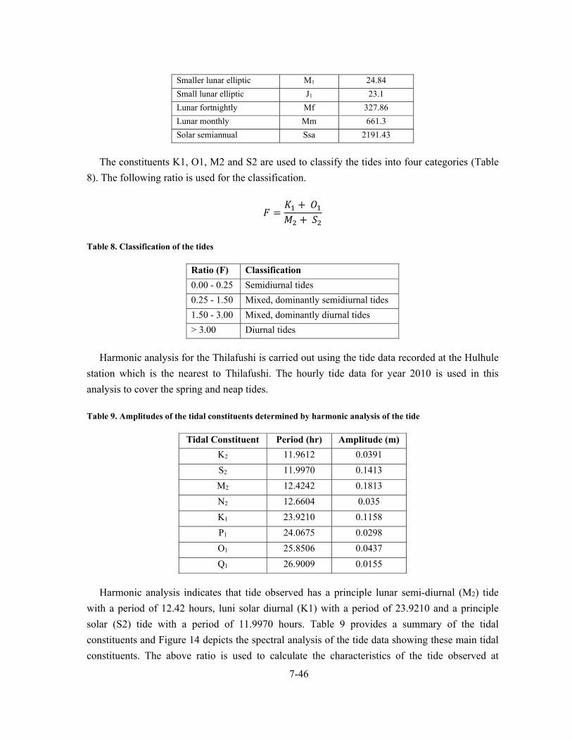
7-46
Smaller lunar elliptic M1 24.84
Small lunar elliptic J1 23.1
Lunar fortnightly Mf 327.86
Lunar monthly Mm 661.3
Solar semiannual Ssa 2191.43
The constituents K1, O1, M2 and S2 are used to classify the tides into four categories (Table
8). The following ratio is used for the classification.
𝐹𝐾 𝑂𝑀 𝑆
Table 8. Classification of the tides
Ratio (F) Classification
0.00 - 0.25 Semidiurnal tides
0.25 - 1.50 Mixed, dominantly semidiurnal tides
1.50 - 3.00 Mixed, dominantly diurnal tides
> 3.00 Diurnal tides
Harmonic analysis for the Thilafushi is carried out using the tide data recorded at the Hulhule
station which is the nearest to Thilafushi. The hourly tide data for year 2010 is used in this
analysis to cover the spring and neap tides.
Table 9. Amplitudes of the tidal constituents determined by harmonic analysis of the tide
Tidal Constituent Period (hr) Amplitude (m)
K2 11.9612 0.0391
S2 11.9970 0.1413
M2 12.4242 0.1813
N2 12.6604 0.035
K1 23.9210 0.1158
P1 24.0675 0.0298
O1 25.8506 0.0437
Q1 26.9009 0.0155
Harmonic analysis indicates that tide observed has a principle lunar semi-diurnal (M2) tide
with a period of 12.42 hours, luni solar diurnal (K1) with a period of 23.9210 and a principle
solar (S2) tide with a period of 11.9970 hours. Table 9 provides a summary of the tidal
constituents and Figure 14 depicts the spectral analysis of the tide data showing these main tidal
constituents. The above ratio is used to calculate the characteristics of the tide observed at
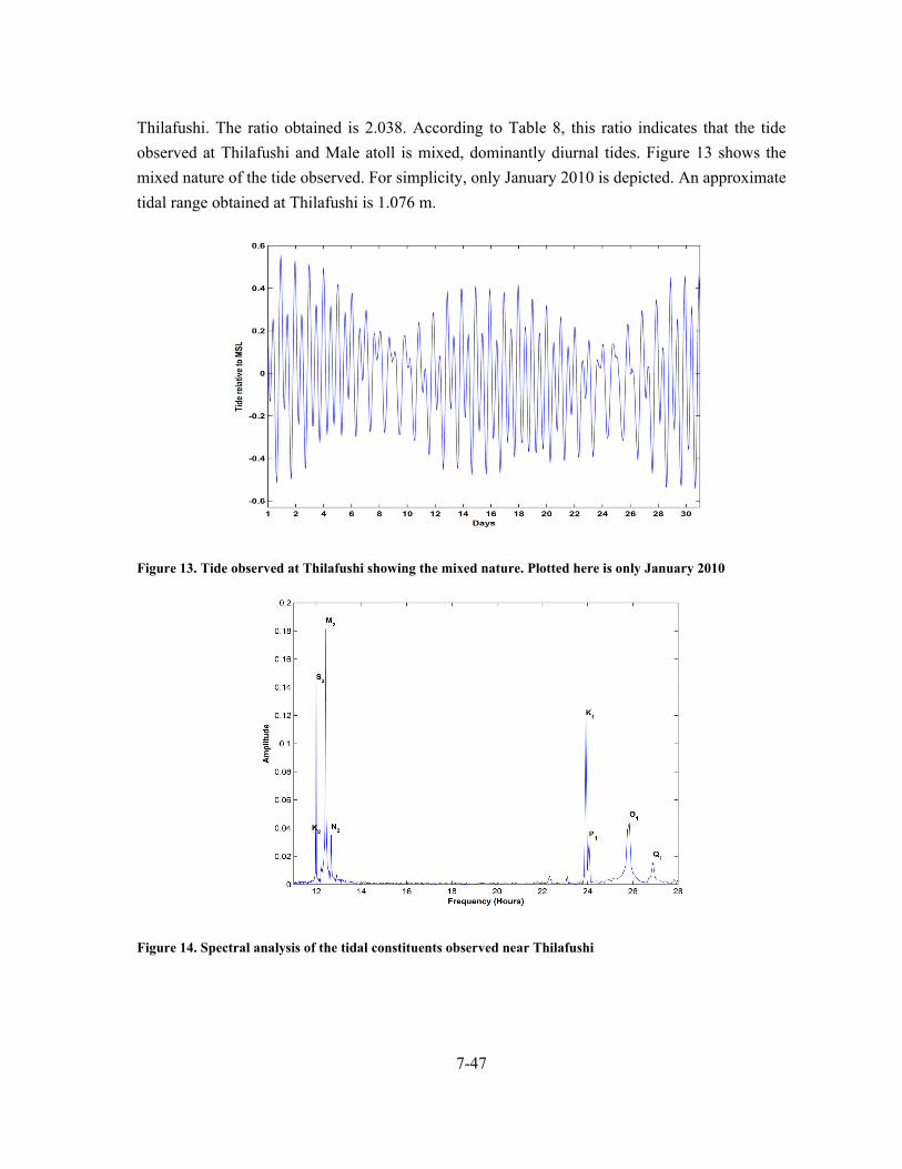
7-47
Thilafushi. The ratio obtained is 2.038. According to Table 8, this ratio indicates that the tide
observed at Thilafushi and Male atoll is mixed, dominantly diurnal tides. Figure 13 shows the
mixed nature of the tide observed. For simplicity, only January 2010 is depicted. An approximate
tidal range obtained at Thilafushi is 1.076 m.
Figure 13. Tide observed at Thilafushi showing the mixed nature. Plotted here is only January 2010
Figure 14. Spectral analysis of the tidal constituents observed near Thilafushi

7-48
7.4.3 Wave and currents
Information on the deep water waves for Maldives is limited (Kench and Brander, 2006), but
wave climate data for the Indian Ocean region surrounding the Maldives reported by Young
(1999) indicate that the dominant swell approaches the Maldives from southerly quarters (Figure
15). Young (1999) reported that on a seasonal basis, swell reaching Maldives is from the south-
southwest from April to November with a peak significant wave height (Hs) of 1.8 m in July,
and from the southeast from December to March with a minimum mean Hs of 0.75 m in March
(Figure 15).
Figure 15. Ten year mean monthly ocean swell height (solid line) and swell direction (dotted line) for the central Maldives (Data from Young (1999))
As part of assessment of wave condition at project area secondary data available at LaMer
Group Pvt Ltd archive was used. One set of data was available from the southern side of
Thilafushi and was used for the purpose of this project.
Water level was sampled at a frequency of 2Hz for a period of 30 minutes and a total of 361
bursts were recorded over a period of 9 days at southern side of Thilafushi. The data is analyzed
using the zero-crossing and spectral analysis method (see Figure 16).
0.0
0.5
1.0
1.5
2.0
0
90
180
270
360
Jan Mar May Jul Sep Nov
Month
Height
Direction
Wav
e H
eigh
t Hs
(m)
Wav
e di
rect
ion
(°)

7-49
Figure 16. Sample of the spectral analysis of the wave data
Among the various parameters analyzed, following characteristics are summarized in Table
10 which shows a sample of 20 bursts.
Significant wave height (Hs)
Mean period of significant wave heights (Ts)
Mean wave period (Tz)
Percentage of capillary waves observed
Percentage of wind waves observed
Percentage of swell waves observed
Percentage of infra-gravity waves observed
Percentage of far-gravity waves observed

7-50
Table 10. Wave characteristics for a sample of 20 bursts (Thilafushi southern side)
Analysis of the results indicates that wind waves are the dominant wave type during the time
of field observation (46.41% of the entire time of observation). However, approximately equal
amount of swell generated waves (45.66%) were also observed during the entire period of
observation (see Figure 17). This could be expected since the observation was carried out during
the southwest monsoon where waves at the south of Thilafushi would be influenced by the
monsoon. The maximum significant wave height observed was 0.32m that had a period of 3.87s.
The average significant height for the entire time of observation was 0.15m.
Figure 17. Dominant wave types for the entire period of observation (Thilafushi southern side)
Swell wave climate data for the Indian Ocean region surrounding the Maldives (Young, 1999)
indicate that the dominant swell approaches from southerly quarters. On a seasonal basis, swell
Date and Time
6/10/2011 22:00
6/10/2011 22:30
6/10/2011 23:00
6/10/2011 23:30
6/11/2011 0:00
6/11/2011 0:30
6/11/2011 1:00
6/11/2011 1:30
6/11/2011 2:00
6/11/2011 2:30
6/11/2011 3:00
6/11/2011 3:30
6/11/2011 4:00
6/11/2011 4:30
6/11/2011 5:00
6/11/2011 5:30
6/11/2011 6:00
6/11/2011 6:30
6/11/2011 7:00
6/11/2011 7:30
Bust # 201 202 203 204 205 206 207 208 209 210 211 212 213 214 215 216 217 218 219 220
Significant wave height (Hs) 0.15 0.14 0.11 0.14 0.13 0.13 0.14 0.15 0.16 0.14 0.18 0.24 0.17 0.15 0.16 0.16 0.14 0.13 0.13 0.12
Mean period of Hs (Ts) 4.45 4.65 4.75 4.87 5.00 4.98 4.79 4.80 4.90 5.26 4.79 4.30 4.95 5.28 4.93 5.32 5.38 5.45 5.71 5.33
Mean wave period (Tz) 4.38 4.40 5.33 4.60 4.93 5.33 5.86 5.68 5.55 5.71 4.69 3.87 4.91 5.08 4.59 5.55 6.23 5.90 6.26 6.04
% of Capillary waves 8.67 19.30 8.10 12.76 14.10 7.47 6.81 8.00 9.22 6.02 10.83 14.43 12.80 5.44 8.70 6.68 2.33 4.80 3.22 2.43
% of Wind waves 51.38 44.40 43.07 43.17 38.25 34.55 27.37 24.24 26.72 42.00 44.28 62.66 35.96 47.06 58.02 59.10 54.77 48.63 52.90 52.96
% of Swell waves 39.47 35.67 47.63 43.77 47.15 57.54 65.29 67.56 63.69 51.74 44.62 22.66 50.94 47.08 33.02 33.96 42.18 46.12 43.12 44.01
% of Infra‐gravity waves 0.35 0.35 0.38 0.24 0.26 0.24 0.13 0.13 0.19 0.15 0.17 0.19 0.15 0.30 0.19 0.20 0.25 0.25 0.31 0.33
% of Far‐gravity waves 0.12 0.28 0.83 0.05 0.25 0.21 0.40 0.08 0.18 0.09 0.10 0.05 0.15 0.12 0.08 0.06 0.47 0.21 0.44 0.28

7-51
is from the south-southwest from April to November with a peak significant wave height (Hs) of
1.8 m in July, and from the southeast from December to March with a minimum mean Hs of
0.75m in March (Kench and Brander, 2006).
The Thilafushi reef system is submitted to three main oceanic climate factors, diffracted swell
(which hits the south side of the reef system (channel between South and North Male’ Atoll); the
southwest monsoon wind waves, and the northeast monsoon wind waves. Figure 18 shows
assumed wave climate of the reef system.
The dominant water current at the reef system (localized to Thilafushi area) is oceanic swell
induced currents. The oceanic swells break at the reef from SE direction (refracted swell waves
received from Vaadhoo Kandu, channel between North and South Male’ Atoll). The swell waves
breaking at the southern side create a current north ward, while the refracted swell waves
entering the channel between Gulhifalhu and Thilafushi creates a current westward. Wind
generated currents are predominant west to east during SW monsoon, while east to west during
NE monsoon. The project site is sheltered during SW monsoon, but during rough spells of NE
monsoon, the area gets very turbid.
Figure 18. Monsoonal wind generated waves effecting Thilafushi reef system
NE monsoonal windwaves
SW monsoonal windwaves
Tidal currents

7-52
7.5 Marine environment
7.5.1 Benthic survey
The reef site T1 is the furthest away from the project impact area. Rock was the dominant
type of benthic cover with a mean percentage cover of 73.80%, while the mean percentage hard
coral cover was 1% (Figure 19).
Figure 19. Mean percentage composition of benthic substrate at site T1. The category Other Algae refers to all other algae apart from Crustose Algae and Macroalgae
Figure 20. General condition of the reef at site T1
0102030405060708090
Hard Coral Other Algae Rock Rubble Sand
Mea
n P
erce
ntag
e C
over
Type of Benthic Cover

7-53
The reef site T2 is within the project impact area. Rock was the dominant type of benthic
cover with a mean percentage cover of 43.53% followed closely by Rubble with a mean
percentage cover of 41.24% (figure). The mean percentage hard coral cover was 0.2% (Figure
21). There were signs that parts of the reef had subsided and there was a lot of large debris on the
reef (Figure 22).
Figure 21. Mean percentage composition of benthic substrate at site T2. The category Other Algae refers to all other algae apart from Crustose Algae and Macroalgae
Figure 22. General condition of the reef at site T2
0
10
20
30
40
50
60
Hard Coral Other Algae Rock Rubble Sand Trash
Mea
n P
erce
ntag
e C
over
Type of Benthic Cover
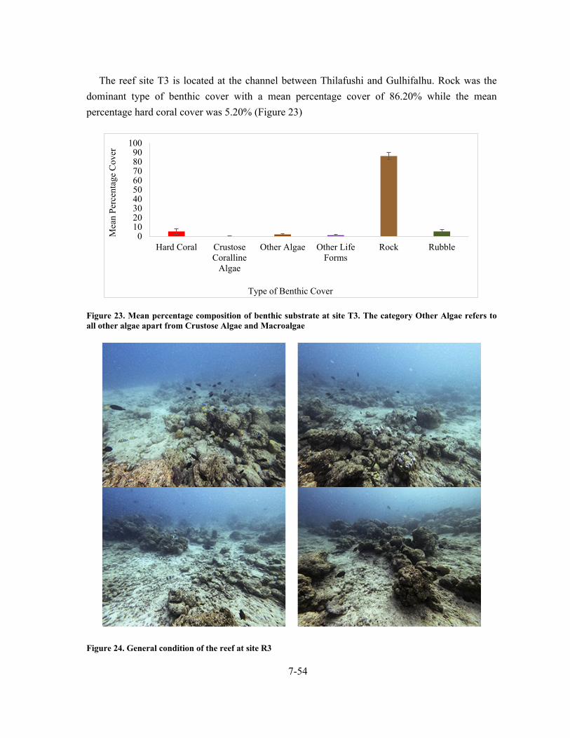
7-54
The reef site T3 is located at the channel between Thilafushi and Gulhifalhu. Rock was the
dominant type of benthic cover with a mean percentage cover of 86.20% while the mean
percentage hard coral cover was 5.20% (Figure 23)
Figure 23. Mean percentage composition of benthic substrate at site T3. The category Other Algae refers to all other algae apart from Crustose Algae and Macroalgae
Figure 24. General condition of the reef at site R3
0102030405060708090
100
Hard Coral CrustoseCoralline
Algae
Other Algae Other LifeForms
Rock Rubble
Mea
n Pe
rcen
tage
Cov
er
Type of Benthic Cover

7-55
The mean percentage hard coral cover was the highest at site T3 at 5.20% (Table 11). Site T2
had the lowest mean percentage hard coral cover at 0.20%. Rock was the dominant type of
benthic substrate at T1 and T2. Rock followed by Rubble was the dominant form of benthic
substrate at T2 (Table 11).
Table 11. Mean percentage cover of the different benthic types across three reef survey sites. The category Other Algae refers to all other algae apart from Crustose Coralline Algae and Macroalgae
Type of Benthic Cover T1 T2 T3
Mean SE Mean SE Mean SE
Hard Coral 1.00 0.70 0.20 0.20 5.20 2.90
Crustose Coralline Algae 0 0 0 0 0.20 0.20
Other Algae 6.00 1.49 5.21 2.45 2.00 0.79
Other Life Forms 0 0 0 0 1.20 0.51
Rock 73.80 4.45 43.53 4.80 86.20 3.70
Rubble 16.40 3.98 41.24 5.26 5.20 2.32
Sand 2.80 1.54 6.42 1.91 0 0
Trash 0.00 0.00 3.40 2.12 0 0
Sites T1 and T2 had only one genera of hard coral (Pocillopora) and site T3 had three genera
of coral (Table 12, Figure 25). Site T3 had the highest hard coral cover amongst the three reef
survey sites, at 5.20% (Table 12, Figure 25).
Table 12. Mean percentage cover of the different genera of coral observed across the reef survey sites
Genus T1 T2 T3
Mean SE Mean SE Mean SE
Astreopora 0.0 0.0 0.0 0.0 0.20 0.20
Pocillopora 1.00 0.70 0.20 0.20 0.20 0.20
Porites (massive) 0 0 0 0 4.80 2.87

7-56
Figure 25. Mean percentage cover of the different genera of coral observed across the reef survey sites
7.5.2 Reef Fish Survey
Site T3 had the highest overall abundance of fish, whereas site T2 had the highest overall
diversity of fish species amongst the three surveyed sites (Table 13). Site T1 had the lowest
overall abundance and diversity of fish species (table). Site T3 had the highest abundance of
herbivorous fish whereas site T2 had the highest diversity of herbivorous fish amongst.
Table 13. Species composition and abundance of reef-associated fish observed during the fish survey
Family Species Common Name Functional
Group Site
T1 T2 T3
Herbivores
Acanthuridae Acanthurus auranticavus Ring-tail Surgeonfish Grazer 3 0 3
Acanthuridae Acanthurus leucosternon Powder-blue Surgeonfish Grazer 2 2 5
Acanthuridae Acanthurus lineatus Lined Surgeonfish Grazer 0 3 0
Acanthuridae Acanthurus nigricauda Eye-line Surgeonfish Browser 3 1 7
Acanthuridae Acanthurus triostegus Convict Surgeonfish Browser 0 1 1
Acanthuridae Ctenochaetus striatus Fine-lined Bristletooth Browser 31 26 40
Acanthuridae Naso fageni Horse-face Unicorn Browser 0 15 0
Acanthuridae Naso vlamingii Big-nose Unicornfish Browser 0 1 0
Acanthuridae Zebrasoma desjardinii Sailfin Tang Grazer 1 0 1
Acanthuridae Zebrasoma scopas Brown Tang Grazer 0 4 0
Pomacentridae Plectroglyphidodon lacrymatus
Jewel Damsel Browser 0 4 0
Scaridae Chlorurus sordidus Shabby Parrotfish Browser 3 12 21
Scaridae Hipposcarus harid Longnose Parrotfish Grazer 0 0 3
Scaridae Scarus frenatus Bridles Parrotfish Grazer 0 0 1
Scaridae Scarus niger Dusky Parrotfish Grazer 2 0 1
0
1
2
3
4
5
6
T1 T2 T3
Mea
n P
erce
ntag
e C
over
Site
Astreopora Pocillopora Porites (massive)

7-57
Scaridae Scarus prasiognathos Green-faced Parrotfish Grazer 0 0 3
Scaridae Scarus russelii Eclipse Parrotfish Grazer 0 0 2
Scaridae Scarus scaber Five-saddled Parrotfish Grazer 0 1 0
Scaridae Scarus tricolor Three-colour Parrtofish Grazer 0 2 0
Zanclidae Zanclus cornutus Moorish Idol Browser 1 5 0
Carnivores
Balistidae Balistapus undulatus Striped Triggerifish Browser 1 0 0
Balistidae Melichthys indicus Indian Triggerfish Browser 3 0 3
Balistidae Odonus niger Blue Triggerfish Browser 15 4 0
Balistidae Sufflamen bursa Boomerang Triggerfish Browser 0 0 2
Balistidae Sufflamen chrysopterum Half-moon Triggerfish Browser 3 1 0
Chaetodontidae Chaetodon auriga Threadfin Butterflyfish Coralivore 0 0 2
Chaetodontidae Chaetodon citrinellus Citron Butterflyfish Coralivore 0 0 1
Chaetodontidae Chaetodon falcula Double-saddle Butterflyfish
Coralivore 0 2 0
Chaetodontidae Chaetodon guttatissimus Spotted Butterflyfish Coralivore 2 0 2
Chaetodontidae Chaetodon kleinii Brown Butterflyfish Coralivore 3 7 4
Chaetodontidae Chaetodon lunula Racoon Butterflyfish Coralivore 0 0 2
Chaetodontidae Chaetodon trifasciatus Pinstriped Butterflyfish Coralivore 3 0 1
Chaetodontidae Chaetodon xanthocephalus
Yellow-head Butterflyfish Coralivore 1 0 1
Chaetodontidae Forcipiger flavissimus Long-nose Butterflyfish Coralivore 0 0 2
Chaetodontidae Forcipiger longirostris Very-long-nose Butterflyfish
Coralivore 5 1 0
Chaetodontidae Hemitaurichthys zoster Black Pyramid Butterflyfish
Planktivore 0 1 0
Fistularidae Fistularia commersonii Smooth Flutemouth Predator 0 7 0
Haemulidae Plectorhinchus gibbosus Brown Sweetlips Browser 0 2 0
Haemulidae Plectorhinchus vittatus Oriental Sweetlips Browser 0 2 0
Holocentridae Sargocentron caudimaculatum
White-tail Squirrelfish Predator 0 1 2
Labridae Cheilinus trilobatus Triple-tail Maori Wrasse Browser 0 2 0
Labridae Gomphosus caeruleus Bird Wrasse Browser 0 0 1
Labridae Halichoeres chrysotaenia Vrolik's Wrasse Browser 0 2 0
Labridae Halichoeres hortulanus Checkerboard Wrasse Browser 1 3 0
Labridae Hemigymnus fasciatus Banded Thicklip Wrasse Browser 0 1 0
Labridae Labroides dimidiatus Blue-streak Cleaner Wrasse
Browser 3 0 0
Labridae Stethojulis albovittata Blue-lined Wrasse Browser 0 1 0
Labridae Thalassoma amblycephalum
Two-tone Wrasse Planktivore 12 0 5
Labridae Thalassoma hardwicke Six-bar Wrasse Browser 0 0 1
Labridae Thalassoma lunare Moon Wrasse Browser 3 0 0
Lethrinidae Lethrinus harak Black-blotched Emperor Predator 1 0 0
Lethrinidae Monotaxis grandoculis Large-eye Bream Predator 0 2 0
Mullidae Parapeneus macronema Long-barbel Goatfish Browser 0 3 5

7-58
Mullidae Parapeneus trifasciatus Double-bar Goatfish Browser 0 0 1
Nemipteridae Scolopsis bilineata Monocle Bream Browser 0 1 0
Pinguipedidae Parapercis millipunctata Thousand-spot Grubfish Browser 0 0 1
Pomacentridae Abudefduf vaigiensis Sergeant Major Browser 0 9 30
Pomacentridae Chromis dimidiata Two-toned Puller Planktivore 1 4 0
Pomacentridae Chromis viridis Green Puller Planktivore 3 0 0
Pomacentridae Dascyllus trimaculatus Three-spot Humbug Browser 0 28 15
Pomacentridae Pomacentrus caeruleus Blue-yellow Damsel Planktivore 4 0 0
Pomacentridae Pomacentrus chrysurus White-tail Damsel Browser 0 2 0
Serranidae Aethaloperca rogaa Red-flushed Grouper Predator 1 0 0
Serranidae Epinephelus fasciatus Blacktip Grouper Predator 0 0 2
Serranidae Cephalopholis nigrippinis Blackfin Rock Cod Predator 3 0 0
7.5.3 Seawater quality
Table 14 shows the physical parameters which were assessed from the samples collected
during the survey. Results given are the average of 5 readings for each site. As evident from the
results, all physical parameters tested are within normal range for seawater.
Table 15 shows tests results for turbidity which was assessed by sending samples to the
MWSC Water Quality Assurance Laboratory. Water quality test reports from MWSC are shown
on Appendix 6 of this report.
Table 14. Water quality measurements taken in-situ with the Hanna HI9829 multiprobe meter
Table 15. Turbidity test results from MWSC Lab
Parameter T2/SW1 T3/SW2
Physical appearance Clear with particles Clear with particles
Turbidity (NTU) 0.191 0.155
Seawater quality at the areas surveyed was seen to be within normal conditions.
Site pH Dissolved
Oxygen (mg/L) Electrical
Conductivity (μS/cm) Total Dissolved
Solids (ppm) Salinity
(PSU) Temperature
(°C)
T2/ SW1 7.52 4.13 4909.4 2454.80 31.92 29.9
T3/ SW2 7.55 4.19 5147.8 2574.00 33.68 29.7

7-59
7.6 Bathymetry
Bathymetric survey was carried out at the proposed project area and adjacent areas (east and
western side). The bathymetric survey shows that the water depth at the project area is -1.6m to
-3.4m MSL at the reef edge area and very steep drop off exceeding -30m MSL. Bathymetric
survey map is shown on Appendix 7 of this report.
7.7 Socio-economic environment
7.7.1 Economic activities undertaken surrounding the facility
The plot adjacent to the south of MPL plot belongs to RKL Group Pvt Ltd. The plot is used
by the company for repair of their vehicles and equipment.
Harbour area to the north of MPL plot is used by the Greater Male’ Industrial Zone Ltd as the
main harbour for the staff of the corporation.
7.7.2 Accessibility and transport
Thilafushi can be accessed via sea, either on their ferries or through hire of private transfer.
Permission to travel to Thilafushi has to be obtained from GMIZL prior to travel. However, if
travelling to a specific plot, this can be arranged through the plot owners.
7.8 Hazard Vulnerability
Hazard vulnerability of Thilafushi is assessed based on the literature available and field data
collection. National Disaster Management Authority has a draft version of revision of updates to
the risk profile of Maldives (NDMA, 2019 unpublished).
Tsunami and earthquakes
As per the revised risk profile, the region which hosts Thilafushi falls in to high risk category
in terms of tsunami risk (Figure 26). As seen in below figure, the eastern atolls, especially
islands along the eastern fringe of the eastern atolls are more exposed to the threat of tsunami
than the western atolls. This is due to the fact that the major tsunami hazard is from the east
(Sumatra), although as reported in NDMA (2019, unpublished) there is also a low risk from the
north and south.

7-60
Figure 26. Tsunami hazard in selected islands in Maldives (figure derived from: NDMA, 2019 unpublished)
Figure 27 shows the seismic hazard map of Maldives, where Hazard zones are divided into 5
zones. As evident from the figure, risk of earthquakes is the highest in the southern atolls,
especially Seenu Atoll. Thus, Thilafushi and associated region has low risk of earthquakes and
moderate risk due to tsunami.

7-61
Figure 27. Seismic hazard map of Maldives (figure derived from: NDMA, 2019 unpublished)
Cyclones and storm surge
Hazardous weather systems, other than general monsoons (heavy rain and strong winds) that
affect Maldives are tropical storms (tropical cyclone) and severe local storms (thunder
storms/thunder squalls). Tropical cyclones are extreme weather events with positive and negative
consequences. At times, these are very destructive due to associated strong winds (often
exceeding 150 kmph), heavy rainfall (often exceeding 30 to 40 cm in 24 hours) and storm tides
(often exceeding 4 to 5 meters). Strong winds can damage structures, houses, communication
systems, roads, bridges and vegetation. Heavy rainfall can cause serious flooding. Storm surge is
a sudden rise of sea level elevation along the coast caused by cyclonic winds. Sea level also rises
twice daily due to astronomical reasons. The combined effect of surge and tide is known as
storm tide. Storm tides can cause catastrophic results in low lying areas, flat coast and island
territories such as Maldives.
As evident from Figure 28, the northern atolls are more affected by cyclones and storms and
associated storm surge. Hence region hosting Thilafushi has moderate probability of cyclonic
winds and storm.

7-62
Figure 28. Tropical cyclones crossing Maldives region during 1891 to 2014 (left), and storm surge hazard to selected islands in Maldives (right) (figure derived from: NDMA, 2019 unpublished)
Based on these findings, Thilafushi has high probability of impact due to tsunami, and
moderate probability of impact due to storm surges and flooding and cyclones. Therefore, proper
mitigation procedures should be in place (disaster management program) which should enable
the island to sustain in the event of unpredictable environmental disasters.

8-63
8 Stakeholder Consultations 8.1 Consultation with EPA
Consultation with EPA was held during the Scoping meeting for the EIA for the project. The
Scoping meeting for the project was held on the 25th of December 2018 with participation from
representatives of the proponent, Consultant, EPA and the Greater Male’ Industrial Zone
Limited. The TOR for the project was finalized by EPA based on discussions carried out at the
meeting, apart from which, EPA did not have any additional concerns or issues. However, they
did stress to ensure inclusion in the EIA report, of the reason for earlier structure failure and
identify the ways in which these issues have been addressed in the revised design. List of
participants of the meeting is included in Appendix 8 of the report.
8.2 Consultation with Greater Male’ Industrial Zone Limited
Personnel consulted: Mr. Ahmed Aiman Shareef, Manager, Planning and Projects (Contact
No: 7236734)
The harbour adjacent to the project plot is used by the GMIZL for their ferry operations.
Consultation with Greater Male’ Industrial Zone Ltd (GMIZL) was carried out via telephone on
the 5th of August 2020. Consultant briefed the personnel from GMIZL regarding the project an
enquired whether he had any concerns regarding the proposed work. In response he stated that he
had a few concerns, which are highlighted below:
GMIZL are concerned that proposed works might have an impact on the access to their
harbour, and request for this to be taken into account during both construction and
operations.
Since the plot at Maldives Petroleum Links, is used for fuel storage, they have concerns
as to degree of compliance with MNDF regulations regarding fuel storage and as to
whether the buffer zone around the area is sufficient. It is very important that the project
works and the site conditions are compliant with MNDF regulations.
Given that proposed works is the construction of structure along the shoreline, it is
important that the design and work is also compliant with the Construction act, as well as
with the different compliance checks which guide the development of projects conducted
by GMIZL. Compliance and regulatory checks should be carried out during EIA work
and outside the EIA work as well. He further informed that once GMIZL is officially
informed about the project, they will then proceed to check for these compliance
components and the issue would also be presented to the Board for their approval.

8-64
Consultant enquired regarding the procedure to be followed by those who have leased plots in
Thilafushi, prior to carrying out similar projects within their plot.
Personnel from GMIZL stated that since this was a modification to an existing
development, the lessee does not have to get the approval prior to EIA stage, as in effect,
approval has been given during initial development. however, they would have to inform
GMIZL, where the Board would then discuss the proposal and make a decision.
However, if it was development of newly leased plots, the lessee would have to provide a
conceptual plan for approval by GMIZL.
8.3 Consultation with RKL facility (adjacent property)
Personnel consulted: Mr. Ahmed Saeed Mohamed, Site Engineer (Contact No: 7583810)
Consultation with RKL Group Pvt Ltd was carried out via telephone on the 5th of August
2020. Personnel consulted with stated that he had no issues or concerns regarding the project and
gave a brief overview of the work they do at their plot. He further stated that they have a barge
and landing craft which are anchored near their berthing area and which could be moved if
required during project construction work.

9-65
9 Environmental Impacts 9.1 Impact Identification
Various methods are available to categorize impacts and identify the magnitude and
significance of the impact, such as checklists, matrices, expert opinion, modelling etc. Impacts
on the environment from various activities of the project construction work (constructional
impacts) and post construction (operational impacts) have been identified through interviews
with the project management team, field data collection surveys and based on past experience in
similar development projects. Data collected during field surveys can be used to predict
outcomes of various operational and construction activities on the various related environmental
components. This data can also be used as a baseline for future monitoring of the environment.
Possible impacts arising from the construction and operation works are described according to
their location, extent (magnitude) and characteristics. They are also further categorized by
intensity of impacts (negligible, minor, moderate and major) for identifying best possible
remedial (mitigation measures) action to be taken. Below are the impact categories.
Table 16. Impact prediction categorized
Impact category
Description Reversible/ irreversible
Cumulative impacts
Negligible The impact has no significant risk to environment either short term or long term
Reversible No
Minor The impact is short term and cause very limited risk to the environment
Reversible No
Moderate Impacts give rise to some concern, may cause long term environmental problems but are likely short term and acceptable
Reversible May or may not
Major Impact is long term, large scale environmental risk
Reversible and Irreversible
Yes, mitigation measures has to be addressed
The concept of the Leopold Matrix (Leopold et. al., 1971) has been used to classify the
magnitude and importance of possible impacts which may arise during the constructional and
post constructional stage of the proposed project. This is one of the best-known matrix
methodology used for identifying the impact of a project on the environment. It is a two-
dimensional matrix which cross references between the activities which are foreseen to have
potential impacts on the environment and the existing conditions (environmental and social)
which could be affected.
The matrix has the actions which may cause an impact on the horizontal axis and the
environmental conditions which may be impacted on the vertical axis. While the original
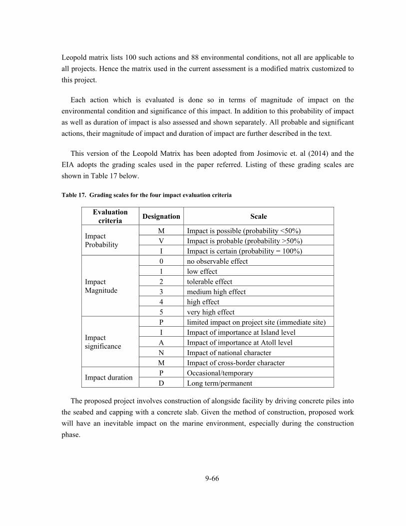
9-66
Leopold matrix lists 100 such actions and 88 environmental conditions, not all are applicable to
all projects. Hence the matrix used in the current assessment is a modified matrix customized to
this project.
Each action which is evaluated is done so in terms of magnitude of impact on the
environmental condition and significance of this impact. In addition to this probability of impact
as well as duration of impact is also assessed and shown separately. All probable and significant
actions, their magnitude of impact and duration of impact are further described in the text.
This version of the Leopold Matrix has been adopted from Josimovic et. al (2014) and the
EIA adopts the grading scales used in the paper referred. Listing of these grading scales are
shown in Table 17 below.
Table 17. Grading scales for the four impact evaluation criteria
Evaluation criteria
Designation Scale
Impact Probability
M Impact is possible (probability <50%) V Impact is probable (probability >50%) I Impact is certain (probability = 100%)
Impact Magnitude
0 no observable effect 1 low effect 2 tolerable effect 3 medium high effect 4 high effect 5 very high effect
Impact significance
P limited impact on project site (immediate site) I Impact of importance at Island level A Impact of importance at Atoll level N Impact of national character M Impact of cross-border character
Impact duration P Occasional/temporary D Long term/permanent
The proposed project involves construction of alongside facility by driving concrete piles into
the seabed and capping with a concrete slab. Given the method of construction, proposed work
will have an inevitable impact on the marine environment, especially during the construction
phase.

9-67
The severity of impacts is predicted by reviewing the design plans and construction
methodologies. Mitigation measures are formulated in light of the information revealed by the
project engineers.
9.2 Limitation or uncertainty of impact prediction
Uncertainty of impact prediction are mainly due to the lack of long term data, inherent
complexity of ecosystem and lack of coordinated monitoring programs with consistent
methodologies which can be used to predict outcomes or reliability of predictions of previous
projects.
The impacts are predicted by reviewing the survey data collected during field visits and
information revealed by the designers and engineers. The data collected during field visit is
limited in terms of number of days to a week or few more, which limits the overall
understanding of even the short term environmental conditions.
The time limitation of EIA field data collection and report preparation is also a hindrance to
properly understanding the environmental factors dictating the conditions of the habitat.
9.3 Constructional Impacts
In any development project major direct impacts to the environment (either short term or long
term) occur mainly during the construction phase. Potential direct or indirect impacts on the
environment from the proposed works include:-
Loss of marine habitat and disturbance to the lagoon bottom;
Pollution of the natural environment; and
Risk of accidents and pollution.
9.3.1 Direct loss of marine habitat and disturbance to the lagoon
bottom
Quantitative assessment at the project site showed that benthic substrate was dominated by
rock and rubble, with hard coral cover of 0.2%. Therefore, direct impact on marine habitat due to
proposed work at the site is anticipated to be almost negligible.

9-68
9.3.2 Impact due to pollution of natural environment
Since the project scope is limited to construction of alongside berthing facility through piling
works, impacts due to pollution of natural environment is limited. Accidental spillage of oil and
solid waste are the possible pollution sources. Impact of natural environment due to pollution is
thought to be minor as all the construction waste could be disposed of directly at Thilafushi on a
daily basis.
9.3.3 Impact on accessibility to nearby facilities (VIP harbor and
RKL facility)
Proposed construction work has the potential to hinder access to adjacent plots, during the
construction phase. However, these have been addressed through stakeholder consultations as
well, and the proponent will ensure that there is a clear pathway of access to both plots, thus
minimizing this impact.
9.3.4 Risk of accidents
The risk of accidents is an inevitable part of any construction project. Depending on the
nature and scope of the project, it is anticipated that the risk of accidents due to this project is
minor to moderate. However, work will be carried out by experienced contractors, thus further
minimizing impact potential.
9.4 Operational impacts
9.4.1 Impact on hydrodynamic regime around the island
The proposed construction of the alongside berthing facility is expected to cause minimal
changes to the existing hydrodynamic regime on the eastern side of the island, as berthing
facility not alter the shoreline around the area.
9.4.2 Accidental spills and pollution
Pollution and accidental spills is a potential negative impact during the operation of the
facility, while cargo is being loaded and unloaded and during filling up of fuel barges.

9-69
9.4.3 Operation of a better equipped facility
Construction of a bigger alongside berthing facility at the site will allow larger vessels to load
and unload their cargo at the site. This would in turn allow for more efficient functioning of the
facility and have a more positive impact on the economy on the whole.
9.5 Impact Analysis
An analysis of the impacts due to the project was done using the Leopold matrix. Impacts are
assessed according to probability of impact, significance of impact, magnitude of impact and
duration of impact. Table 18 to Table 21 gives the assessment for the impacts, and these are
further discussed above with their scoring.
As evident from Tables below, most impacts envisaged during the construction phase have a
low impact on the environment, while positive impact envisaged during operational phase is
envisaged to be moderate.
Table 18. Assessment of Probability of impact from project activities
En
visa
ged
imp
act
fact
ors
Construction phase Operational phase
Op
erat
ion
of
h
eavy
m
ach
iner
y
Shee
t p
ilin
g
Acc
iden
tal
spill
ages
Imp
act
on n
earb
y p
lots
Pol
luti
on a
nd
Acc
iden
tal s
pills
Op
erat
ion
of
the
faci
lity
Physical components
Seawater quality M M V V
Coastal zone V V
Hydrodynamics M
Air M V
Noise M V I
Biological components
Ecosystem quality M I M
Diversity of flora M
Diversity of fauna M
Socio-economic components
Access M
Economy I
Accidents V M V V

9-70
Table 19. Assessment of significance of impact from project activities
En
visa
ged
imp
act
fact
ors
Construction phase Operational phase
Op
erat
ion
of
he
avy
m
ach
iner
y
Sh
eet
pili
ng
Acc
iden
tal
spil
lage
s
Imp
act
on n
earb
y pl
ots
Pol
luti
on a
nd
Acc
iden
tal s
pills
Op
erat
ion
of
the
faci
lity
Physical components
Seawater quality P P P P
Coastal zone P P
Hydrodynamics P
Air P P
Noise P P P
Biological components
Ecosystem quality P P P
Diversity of flora P
Diversity of fauna P
Socio-economic components
Access P
Economy I
Accidents P P P P
Table 20. Assessment of duration of impact due to project activities
En
visa
ged
imp
act
fact
ors
Construction phase Operational phase
Op
erat
ion
of
he
avy
m
ach
iner
y
Sh
eet
pili
ng
Acc
iden
tal
spill
ages
Imp
act
on n
earb
y p
lots
Pol
luti
on a
nd
A
ccid
enta
l sp
ills
Op
erat
ion
of
the
faci
lity
Physical components
Seawater quality P P P P
Coastal zone P P
Hydrodynamics D
Air P P
Noise P P P
Biological components
Ecosystem quality P P P
Diversity of flora P
Diversity of fauna P
Socio-economic components
Access P
Economy D
Accidents D D P D

9-71
Table 21. Assessment of magnitude of impact due to project activities
En
visa
ged
imp
act
fact
ors
Construction phase Operational
phase
Su
m
Ave
rage
Op
erat
ion
of
he
avy
m
ach
iner
y
Sh
eet
pili
ng
Acc
iden
tal
spil
lage
s
Imp
act
on n
earb
y pl
ots
Pol
luti
on a
nd
Acc
iden
tal s
pil
ls
Op
erat
ion
of
the
faci
lity
Physical components
Seawater quality 2 3 3 0 3 0 11 1.83
Coastal zone 0 2 3 0 0 0 5 0.83
Hydrodynamics 0 0 0 0 0 1 1 0.17
Air 1 1 0 0 0 0 2 0.33
Noise 1 1 0 1 0 0 3 0.50
Biological components
Ecosystem quality 1 1 2 0 2 0 6 1.00
Diversity of flora 1 0 0 0 0 0 1 0.17
Diversity of fauna 1 0 0 0 0 0 1 0.17
Socioeconomic components
Access 0 0 0 2 0 0 2 0.33
Economy 0 0 0 0 0 3 3 0.50
Accidents 5 5 3 0 3 0 16 2.67 Cumulative values of IF according to
environmental factors 12 13 11 3 8 4
Average 1.09 1.18 1.00 0.27 0.72 0.36

10-72
10 Alternatives
Given the need and scope of work and proposed methodology, no alternatives are available
for the project. The only alternative which can be considered is the no project scenario. If this
option is selected, the environmental impacts due to the project will be avoided.
The existing facility was designed more as a protection structure than a berthing facility (after
the previous slope and structure failure issues faced at the site). Hence, at present, only smaller
vessels and fuel barges are able to load and unload at existing berthing facility at the plot for
Maldives Petroleum Links Pvt Ltd. With increased demand for construction materials and fuel,
there is a need for a facility that could allow larger vessels to unload bulk materials such as
construction materials. Furthermore, such a facility would allow bigger fuel barges to load and
unload fuel.
If the no project scenario was to be selected, the site will remain as it is and the need for the
project would not be fulfilled. Given that environmental impacts due to the project are mostly
minor, mainly due to present condition of the site, selection of the no project scenario is not
considered a feasible option and is thus cancelled.

11-73
11 Mitigation Plan
Mitigation measures that are explored below (Table 22) emerged out of the discussions and
consultations during work on this report with the project proponent and based on literature.
Mitigation measures are proposed to reduce or eliminate the severity of any predicted adverse
environmental effects and improve the overall social and environmental performance of the
project.
Mitigation measures are discussed both for the construction and operation stage of the project.
During the construction stage it is important to take measures to minimize impact on
environment due to methods used.
Commitment from the proponent for carrying out the proposed mitigation and monitoring
plan is given in the declaration of the proponent.

11-74
Table 22. Identified possible impacts and their relevant mitigation measures
Possible Impacts Mitigation measures Location Time frame
(Phase) Impact
intensity Institutional
responsibility Cost (USD)
Noise and air pollution
Avoid unnecessary operation of machinery and equipment
Limit use of heavy machinery to project site only
Work site During
construction Minor, short term impact
Project proponent/ contractor
N/A
Accidental oil spills
Follow fuel handling regulation of MNDF.
Have emergency clean-up gear on standby
Work site During
construction and operation
Moderate, long term
Project proponent/ contractor
N/A
Risk of accidents and health and safety of workers
Have emergency vessels on standby to transfer injured staff to Male’ in case of accidents
Work site During
construction Minor, short term impact
Project proponent/ contractor
N/A
Physical damage to reef habitat
Avoid trampling/ used of machinery and equipment on areas outside of project boundary
Lagoon During
construction Minor, short term impact
Project proponent/ contractor
N/A
Littering on terrestrial and marine environment
Pre-planning ways of collecting and disposing of waste at Thilafushi island itself
Project development
plot
During construction
Minor, short term impact
Project proponent/ contractor
N/A

12-75
12 Monitoring Program
Monitoring is the systematic collection of information over a long period of time. It involves
the measuring and recording of environmental variables associated with the development
impacts. Monitoring is needed to;
Compare predicted and actual impacts
Test the efficiency of mitigation measures
Obtain information about responses of receptors to impacts
Enforce conditions and standards associated with approvals
Prevent environmental problems resulting from inaccurate predictions
Minimize errors in future assessments and impact predictions
Make future assessments more efficient
Provide ongoing management information
Improve EIA and monitoring process
Impact and mitigation monitoring is carried out to compare predicted and actual impacts
occurring from project activities to determine the efficiency of the mitigation measures. This
type of monitoring is targeted at assessing human impacts on the natural environment. Impact
monitoring is supported by an expectation that at some level anthropogenic impacts become
unacceptable and action will be taken to either prevent further impacts or re-mediate affected
systems. Mitigation monitoring aims to compare predicted and actual (residual) impacts so that
effectiveness of mitigation measures can be determined.
Monitoring works have only been identified for the construction phase of the project, as
operational phase is not envisaged to have further additional impacts on the environment.
Monitoring works will be carried out according to the monitoring programme in Table 23. Cost
for the monitoring (data collection) activities will be covered by the proponent (commitment to
carrying out and financing the mitigation and monitoring work is given in the Proponents
Declaration on Page vii).
The EIA monitoring report structure provided in the EIA report bylaw 2012 (2012/R-27) shall
be used for the monitoring report preparation. Monitoring reports will be submitted at the
intervals as specified in Table 23 for monitoring work during operational phase of the project.
Although there is no monitoring identified for the operational phase of the project, the
Consultant recommends monitoring of and recording / reporting of any accidental fuel spill
incidents.

12-76
Table 23. Monitoring programme for construction phase of the project
Monitoring parameter Location Frequency or timing of monitoring
and report submission Cost
(MRF) Seawater quality tested for
Temperature pH Salinity Turbidity Electrical Conductivity Total Dissolved Solids Dissolved Oxygen
T2/SW1, T3/SW2
Every 2 months 8,000 per survey

13-77
13 Conclusion
The environmental impacts associated with the proposed project are considered minor. This
conclusion is based on the evaluation of various components of the proposed project,
implementation methods discussed, findings of the existing environment and environmental
components that are likely to be affected. The significant environmental component associated
with the project is the marine environment.
Findings of the environmental survey showed that the proposed project area has almost
negligible hard coral cover. The area was dominated by rock and rubble. There were also signs
that parts of the reef had subsided and there was a lot of large debris on the reef (due to structural
failure of previous berthing facility at the site).
The operation of a better equipped, larger berthing facilities, upon completion has a major
positive impact. This will allow berthing of larger vessels and more efficient unloading of bulk
materials such as construction materials. Bigger fuel barges will also be able to use the facility to
load and unload fuel.
Therefore, with due consideration to the environmental components identified above and the
extent of the project activities and their likely and predicted impacts identified, the consultant
concludes that the project components and selected designs are feasible and appropriate
mitigation measures have been considered to correct and minimize unfavorable environmental
changes. The Consultant also stresses the importance of regular monitoring as given in the EIA
report, so as to identify impacts due to the project and rectify any negative impacts.

13-78
Acknowledgements
The consultant acknowledges the contribution provided by the team members in this report
for the valuable contribution to the report and at the field. The consultant also acknowledges the
assistance provided by Maldives Petroleum Links Pvt Ltd.
CVs of team members are given below.

1
Curriculum Vitae
Position Environmental Consultant
Name Shahaama Abdul Sattar
Address G. Helengeli, Lily Magu
Male’, Rep. of Maldives
Contact Mobile: +9607904985
Email: [email protected]
Date of Birth 30 September 1980
Nationality Maldivian
Education Master of Science (MSc) in Fisheries Biology and Fisheries
Management, University of Bergen. Bergen, Norway, 2004 - 2006
Bachelor of Science (BSc.), The Flinders University of South Australia,
Adelaide, South Australia, 1999 - 2001
Membership of
Professional Associations
Small Island Research Group (SIRG) Maldives, Vice President
Countries of Work
Experience
Maldives
Languages
Dhivehi Mother tongue
English Fluent
Employment Record
From: 2008 - 2011
Employer: Marine Research Centre, Ministry of Fisheries and Agriculture, Male’, Maldives.
Position: Fisheries Biologist
From: 2006 to 2008
Employer: Marine Research Centre, Ministry of Fisheries Agriculture and Marine Resources, Male’,
Maldives.
Position: Senior Research Officer
From: 2002 – 2004
Employer: Marine Research Centre, Ministry of Fisheries Agriculture and Marine Resources, Male’,
Maldives.
Position: Research Officer
Line of work at MRC included:
Assessment of the reef and grouper fisheries of Maldives, with surveys to monitor fisheries and
fish species behavior. Compilation and analysis of data, for regular reviews and reporting and
formation of management recommendations. Key role in the formulation of the Grouper Fisheries
Management Plan / Grouper Fisheries and Export Regulation

2
Focal point for the IUCN funded project on identification of reef fish spawning aggregations in
the Maldives through fishermen interviews (2007)
Secretariat and key organizer – Indian Ocean Cetacean Symposium 2009
Project Partner for Maldives for the Darwin Initiative Coral Reef Fish Project, Maldives
MRC Focal Point for the Atoll Ecosystem Conservation Programme, Ministry of Housing and
Environment (2009 – 2011)
Participated in the Biodiversity Valuation survey of Baa Atoll Maldives carried out by AEC
project and IUCN
From: May 2011 – Dec 2012
Employer: Darwin Reef Fish Project / Marine Research Centre (Maldives) and Marine Conservation
Society (UK)
Position: Consultant, Darwin Reef Fish Project (4 year joint collaboration between MRC and MCS,
UK)
Assess the various reef fisheries (grouper, aquarium and food fisheries) of the Maldives and aims
to establish management plans for these fisheries. Provision of technical support and assistance
to the project staff and MRC in implementing the project and formulation of the management
plans.
From: July 2011 – Dec 2011
Employer: Bay of Bengal Large Marine Ecosystem Project
Position: BOBLME Sharks Working Group Coordinator
Coordinator for the Sharks WG of BOBLME project, and work with the focal points in the
member countries, to assist in the formulation and implementation of their National Plans of
Action for Sharks.
From: June 2011 to Present
Employer: Land and Marine Environmental Resource Group Pvt Ltd
Position: Environmental Consultant
Workshops/Seminars Participated
15-21 March 2003 - Training Workshop on the Implementation of Multilateral Agreements in
the Conservation of Biodiversity with special focus on Marine Biodiversity. Kushiro, Japan
14-16 November 2006 – Sixth William R. and Lenore Mote International Symposium – Life
history in Fisheries Ecology and Management. Sarasota, Florida
03-05 March 2008 – Olhugiri and Dhigalihaa Protected Areas Management Planning Workshop.
Eydhafushi, Maldives
11 March 2008 – Applying the Ecosystem Approach to managing Atoll Ecosystems in the
Maldives. Hulhule Island Hotel, Maldives
24-26 March 2008 – Regional Consultation on Preparation of Management Plans for Shark
Fisheries. Beruwela, Sri Lanka
17-19 June 2008 – Workshop on Assessment and Management of the Offshore Resources of
3
South and Southeast Asia. Bangkok, Thailand
22-23 March 2009 – BOBP-IGO National Workshop on Monitoring, Control and Surveillance in
Marine Fisheries. Male’, Maldives
18 – 20 July 2009 – Indian Ocean Cetacean Symposium 2009. Paradise Island Resort and Spa,
Maldives.
09-11 August 2009 – Second Regional Consultation on Preparation of Management Plans for
Shark Fisheries. Kulhudhuffushi, Maldives
24-25 February 2010 – BOBLME Project – National Inception Workshop, Male’, Maldives
2-3 June 2010 – BOBP-IGO Technical Advisory Committee – 5th
Meeting, Male’, Maldives
13-14 September 2010 – BOBLME Fisheries Assessment Working Group – 1st
Meeting, Bangkok,
Thailand
14-16 December 2010 – EWS-WWF 2nd
Marine Conservation Forum for the Gulf Region In
partnership with the Pew Environment Group – Local Actions for Global Challenges, Abu Dhabi,
United Arab Emirates
18-19 January 2011 – Bay of Bengal Large Marine Ecosystem Project – Workshop on the Status
of Marine Managed Areas in the Bay of Bengal, Penang, Malaysia
5-7 July 2011 –Bay of Bengal Large Marine Ecosystem Project – First meeting of the BOBLME
Sharks Working Group, Male’, Maldives
7-8 September 2011 – Workshop to formulate the Grouper Fisheries Management Plan,
DRFP/MRC, Male’, Maldives
15-17 September 2011 – SEAFDEC Special Meeting on Sharks Information Collection in
Southeast Asia, Bangkok, Thailand
10 April 2014 - Stakeholder Consultation to present the National Plan of Action on the
Conservation and Management of Sharks (NPOA-Sharks), Male’, Maldives
Publications
Sattar, S. A., Najeeb, A., Islam, F., Afzal, M. S. and Wood, E. (2012) Management of the grouper
fishery of the Maldives, Proceedings of the 12th International Coral Reef Symposium, Cairns,
Australia, 9-13 July 2012, Session 13E (in press)
Ushan, M., Wood, E., Saleem, M. and Sattar, S. A (2012) Maldives Sharkwatch Report for 2009 -
2010, Proceedings of the 12th International Coral Reef Symposium, Cairns, Australia, 9-13 July 2012,
Session 13D (in press)
Sattar, S. A., Andréfouët, S., Ahsan, M., Adam, M. S., Anderson, C. R. and Scott, L (2012) Status of
the Coral Reef Fishery in an Atoll under tourism development: the case of Central Maldives, Atoll
Research Bulletin 590: 163-186
Sattar, S. A., Amir, H. and Adam, M. S. (2012) Reef fish tagging programme – Baa Atoll Pilot project,
Atoll Research Bulletin 590: 187-200
BOBLME (2011) Report of the BOBLME Sharks Working Group, 5-7 July 2011, Male’ Maldives,
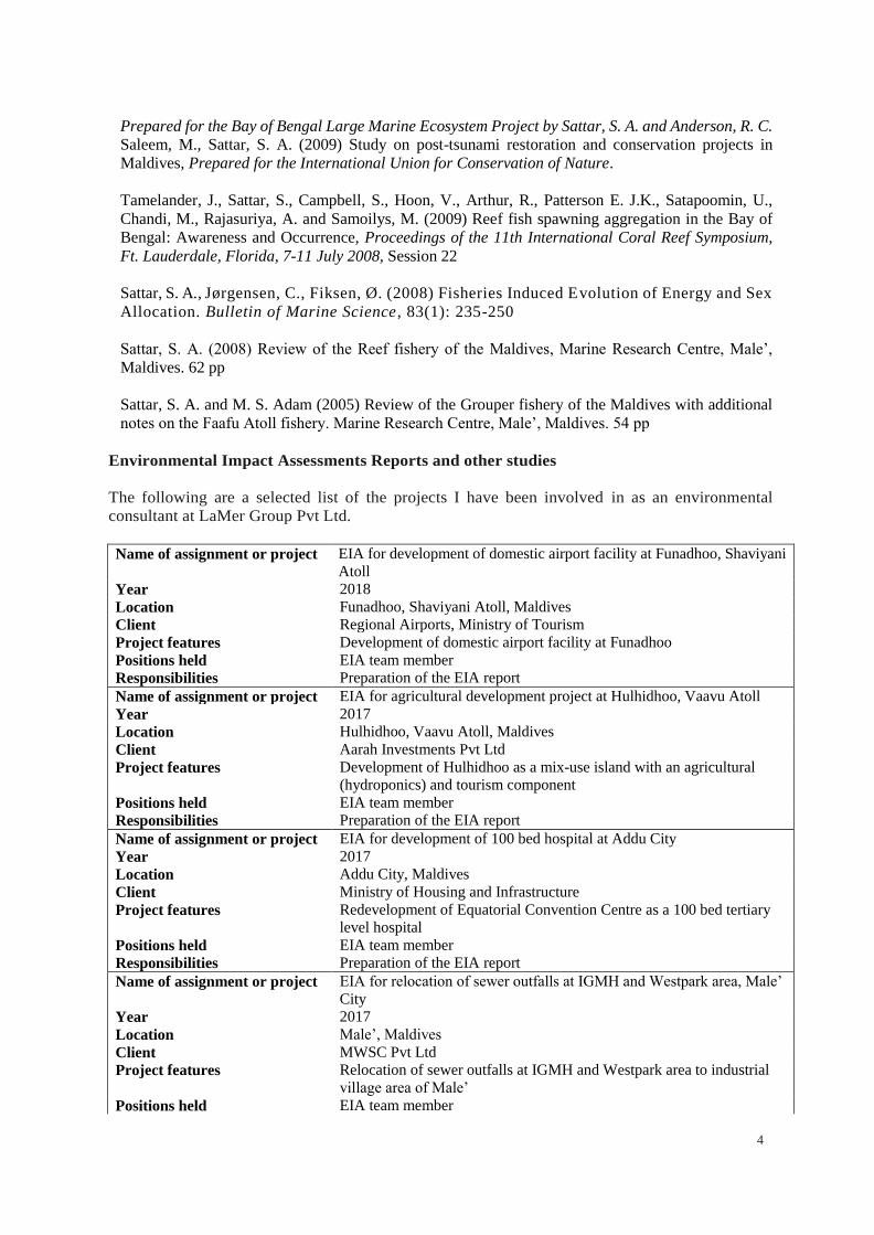
4
Prepared for the Bay of Bengal Large Marine Ecosystem Project by Sattar, S. A. and Anderson, R. C.
Saleem, M., Sattar, S. A. (2009) Study on post-tsunami restoration and conservation projects in
Maldives, Prepared for the International Union for Conservation of Nature.
Tamelander, J., Sattar, S., Campbell, S., Hoon, V., Arthur, R., Patterson E. J.K., Satapoomin, U.,
Chandi, M., Rajasuriya, A. and Samoilys, M. (2009) Reef fish spawning aggregation in the Bay of
Bengal: Awareness and Occurrence, Proceedings of the 11th International Coral Reef Symposium,
Ft. Lauderdale, Florida, 7-11 July 2008, Session 22
Sattar, S. A., Jørgensen, C., Fiksen, Ø. (2008) Fisheries Induced Evolution of Energy and Sex
Allocation. Bulletin of Marine Science , 83(1): 235-250
Sattar, S. A. (2008) Review of the Reef fishery of the Maldives, Marine Research Centre, Male’,
Maldives. 62 pp
Sattar, S. A. and M. S. Adam (2005) Review of the Grouper fishery of the Maldives with additional
notes on the Faafu Atoll fishery. Marine Research Centre, Male’, Maldives. 54 pp
Environmental Impact Assessments Reports and other studies
The following are a selected list of the projects I have been involved in as an environmental
consultant at LaMer Group Pvt Ltd.
Name of assignment or project EIA for development of domestic airport facility at Funadhoo, Shaviyani
Atoll
Year 2018
Location Funadhoo, Shaviyani Atoll, Maldives
Client Regional Airports, Ministry of Tourism
Project features Development of domestic airport facility at Funadhoo
Positions held EIA team member
Responsibilities Preparation of the EIA report
Name of assignment or project EIA for agricultural development project at Hulhidhoo, Vaavu Atoll
Year 2017
Location Hulhidhoo, Vaavu Atoll, Maldives
Client Aarah Investments Pvt Ltd
Project features Development of Hulhidhoo as a mix-use island with an agricultural
(hydroponics) and tourism component
Positions held EIA team member
Responsibilities Preparation of the EIA report
Name of assignment or project EIA for development of 100 bed hospital at Addu City
Year 2017
Location Addu City, Maldives
Client Ministry of Housing and Infrastructure
Project features Redevelopment of Equatorial Convention Centre as a 100 bed tertiary
level hospital
Positions held EIA team member
Responsibilities Preparation of the EIA report
Name of assignment or project EIA for relocation of sewer outfalls at IGMH and Westpark area, Male’
City
Year 2017
Location Male’, Maldives
Client MWSC Pvt Ltd
Project features Relocation of sewer outfalls at IGMH and Westpark area to industrial
village area of Male’
Positions held EIA team member
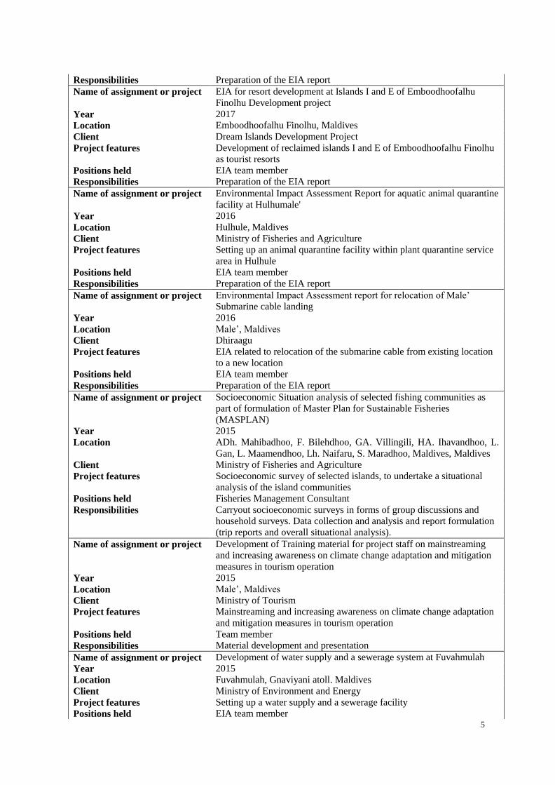
5
Responsibilities Preparation of the EIA report
Name of assignment or project EIA for resort development at Islands I and E of Emboodhoofalhu
Finolhu Development project
Year 2017
Location Emboodhoofalhu Finolhu, Maldives
Client Dream Islands Development Project
Project features Development of reclaimed islands I and E of Emboodhoofalhu Finolhu
as tourist resorts
Positions held EIA team member
Responsibilities Preparation of the EIA report
Name of assignment or project Environmental Impact Assessment Report for aquatic animal quarantine
facility at Hulhumale'
Year 2016
Location Hulhule, Maldives
Client Ministry of Fisheries and Agriculture
Project features Setting up an animal quarantine facility within plant quarantine service
area in Hulhule
Positions held EIA team member
Responsibilities Preparation of the EIA report
Name of assignment or project Environmental Impact Assessment report for relocation of Male’
Submarine cable landing
Year 2016
Location Male’, Maldives
Client Dhiraagu
Project features EIA related to relocation of the submarine cable from existing location
to a new location
Positions held EIA team member
Responsibilities Preparation of the EIA report
Name of assignment or project Socioeconomic Situation analysis of selected fishing communities as
part of formulation of Master Plan for Sustainable Fisheries
(MASPLAN)
Year 2015
Location ADh. Mahibadhoo, F. Bilehdhoo, GA. Villingili, HA. Ihavandhoo, L.
Gan, L. Maamendhoo, Lh. Naifaru, S. Maradhoo, Maldives, Maldives
Client Ministry of Fisheries and Agriculture
Project features Socioeconomic survey of selected islands, to undertake a situational
analysis of the island communities
Positions held Fisheries Management Consultant
Responsibilities Carryout socioeconomic surveys in forms of group discussions and
household surveys. Data collection and analysis and report formulation
(trip reports and overall situational analysis).
Name of assignment or project Development of Training material for project staff on mainstreaming
and increasing awareness on climate change adaptation and mitigation
measures in tourism operation
Year 2015
Location Male’, Maldives
Client Ministry of Tourism
Project features Mainstreaming and increasing awareness on climate change adaptation
and mitigation measures in tourism operation
Positions held Team member
Responsibilities Material development and presentation
Name of assignment or project Development of water supply and a sewerage system at Fuvahmulah
Year 2015
Location Fuvahmulah, Gnaviyani atoll. Maldives
Client Ministry of Environment and Energy
Project features Setting up a water supply and a sewerage facility
Positions held EIA team member

6
Responsibilities Preparation of the EIA report
Name of assignment or project Environmental Impact Assessment for soft coastal protection works at
GDh. Thinadhoo
Year 2014
Location GDh. Thinadhoo, Maldives
Client Ministry of Environment and Energy
Project features Beach Nourishment and Coastal protection
Positions held EIA team member
Responsibilities Preparation of the EIA report
Name of assignment or project Beach Nourishment and Coastal Protection works at a private land at
Praslin, Seychelles
Year 2014
Location Praslin, Seychelles
Client Ahmed Didi
Project features Beach Nourishment and Coastal protection at Praslin, Seychelles
Positions held Environmental assessment team member
Responsibilities Preparation of the report submitted to the client
Name of assignment or project 1500 Housing Unit construction Project Maldives
Year 2014
Location Fuvahmulah, Gadhdhoo, Hoadedhdhoo, Hithadhoo, Holhudhoo,
Madaveli, Thinadhoo, Maldives
Client Ministry of Housing and Infrastructure
Project features Construction of Housing Units at the specified Islands
Positions held EIA team member
Responsibilities Preparation of the EIA report
Name of assignment or project EIA report for Coastal modification at Robinson Club Maldives
Year 2013
Location Ga. Funamaudua, Maldives
Client Robinson Club Maldives, Maldives
Project features Coastal modification at the NW side of the island, construction of geo-
bag revetment and harbor basin maintenance dredging works
Positions held EIA team member
Responsibilities Preparation of the EIA report
Name of assignment or project EIA report for construction of gravity type waste water collection system
at ADh Omadhoo
Year 2013
Location ADh Omadhoo, Maldives
Client ADh Omadhoo Island Council Office
Project features Construction of gravity type waste water collection system and sea
outfall pumping system
Positions held EIA team member
Responsibilities Preparation of the EIA report
Name of assignment or project EIA report for upgrading of Maldive Gas Pvt Ltd Gas jetty
Year 2013
Location Thilafushi, Maldives
Client Maldive Gas Pvt Ltd
Project features Reconstruction of existing gas jetty head and expansion of jetty head
Positions held EIA team member
Responsibilities Preparation of the EIA report
Name of assignment or project EIA report for Resort development at GDh Havvodaa
Year 2013
Location GDh Havvodaa, Maldives
Client Crystal Plaza Pvt Ltd, Maldives
Project features Construction of a resort hotel and all the related amenities
Positions held EIA team member
Responsibilities Preparation of the EIA report

7
Name of assignment or project EIA report for Coastal protection, coastal modification, beach
nourishment, coral nursery setup and entrance channel maintenance
dredging work
Year 2013
Location Gili Lankanfushi, Maldives
Client Gili Lankanfushi, Maldives
Project features Coastal protection, coastal modification, beach nourishment, coral
nursery setup and entrance channel maintenance dredging work
Positions held EIA team member
Responsibilities Preparation of the EIA report
Name of assignment or project EIA report for Harbor development project at Dh. Maaenboodhoo
Year 2013
Location Dh. Maaenboodhoo, Maldives
Client Ministry of Housing and Infrastructure
Project features Development of harbor facility (dredging of harbor basin, construction
of wharfs and breakwater)
Positions held EIA team member
Responsibilities Preparation of the EIA report
Name of assignment or project EIA report for Flood mitigation and reclamation work at Faresmaathoda
Year 2013
Location GDh. Faresmaathodaa, Maldives
Client United Nations Office for Project Services (UNOPS)
Project features Construction of breakwater and reclamation of land
Positions held EIA team member
Responsibilities Preparation of the EIA report
Name of assignment or project EIA report for Development of Domestic Airport Facility
Year 2012
Location Th. Thimarafushi, Maldives
Client Maldives Airports Company Limited
Project features Construction of runway apron
Positions held EIA team member
Responsibilities Preparation of the EIA report
Name of assignment or project EIA report for Wharf reconstruction and upgrading of existing berthing
facility and slipway
Year 2012
Location Thilafushi, Maldives
Client Fuel Supply Maldives Pvt Ltd, Maldives
Project features Reconstruction of wharf and upgrading of existing berthing facility and
slipway
Positions held EIA team member
Responsibilities Preparation of the EIA report
Name of assignment or project EIA report for Resort development at B. Kanifinolhu
Year 2012
Location B. Kanifushi, Maldives
Client Coastline Hotels and Resorts Pvt Ltd, Maldives
Project features Construction of a resort hotel and all the related amenities
Positions held EIA team member
Responsibilities Preparation of the EIA report
Name of assignment or project EIA report for Borehole construction at Cyprea Mrine Food Fish Factory
Year 2012
Location K. Himmafushi, Maldives
Client Cyprea Marine Food Pvt Ltd, Maldives
Project features Construction of a 8 inch borehole at factory premise
Positions held EIA team member
Responsibilities Preparation of the EIA report

8
Name of assignment or project EIA report for resort development at K. Kudavilligili, Maldives
Year 2011
Location K. Kudavilingili, Maldives
Client Yacht Tours Pvt Ltd, Maldives
Project features Construction of resort hotels and all the related amenities. In addition a
large reclamation of the shoreline as additional land as part of the resort
development is also part of the project
Positions held EIA team member
Responsibilities Preparation of the EIA report
Name of assignment or project EIA report for development of city hotel, hospitality institute and resort
development at Gasfinolhu and Bodufinolhu, L. Atoll
Year 2011
Location L. Gan, Bodufinolhu and Gasfinolhu, Maldives
Client Premier Equities Pvt Ltd, Maldives
Project features Construction of a resort hotel and required amenities including a
training hotel for hospitality industry
Positions held EIA team member
Responsibilities Preparation of the EIA report
Referees
Dr. Mohamed Shiham Adam, PhD
Marine Research Centre
Ministry of Fisheries and Agriculture
Male’, Republic of Maldives
Tel. No: +960 331 3681
Email: [email protected]
Dr. Charles Anderson
Certification
I, the undersigned, certify that to the best of my knowledge and belief, this CV correctly describes my
qualifications, my experience, and me. I understand that any willful misstatement described herein may
lead to my disqualification or dismissal, if engaged.
Shahaama A. Sattar Date: October 2018

CURRICULUM VITAE 1. POSITION: Environment Analyst 2. NAME OF FIRM: LaMER Group Pvt.Ltd
3. NAME: Azim Musthag 4. DATE OF BIRTH: 13th December 1985 5. NATIONALITY: Maldivian 6. PERSONAL ADDRESS: M. Anthias, Fulooniya Magu, Malé, Maldives 7. EDUCATION Bachelor of Marine Science (Majoring in Marine Ecology),
Griffith University, Queensland, Australia. DELF (Diplôme d'études en langue française) Level A1 and Level A2
8. MEMBERSHIP OF PROFESSIONAL SOCIETIES: Master Instructor with the Scuba Schools
International (SSI). 9. OTHER TRAINING: Fish Watch Training Workshop conducted by Darwin Reef Fish
Project initiated by the Marine Research Centre of Maldives in
collaboration with Marine Conservation Society (UK) in 2009.
IUCN Manta Ray Workshop in 2013.
National Coral Reef Monitoring Framework monitoring protocols training in 2014 conducted by IUCN Maldives.
10. COUNTRIES OF WORK EXPERIENCE: Maldives and Australia 11. LANGUAGE AND DEGREE OF PROFICIENCY: English - Native or bilingual proficiency
Dhivehi - Native or bilingual proficiency French - Limited working proficiency
12. EMPLOYMENT RECORD: 2005 - 2011 Dive Instructor,
Maldivers Diving Centre, Malé.
2012 – 2014
Dive Instructor, Diveoceanus Dive Centre at Paradise Island Resort
2017 - 2017 Research Assistant Griffith University, Gold Coast, Australia.
2018 (Present) Environmental Analyst Lamer Pvt Ltd
13. DETAILED TASKS
ASSIGNED: WORK UNDERTAKEN THAT BEST ILLUSTRATES CAPABILITY TO HANDLE TASKS:
Project: Ecological surveys for the proposed, potential UNESCO
biosphere reserves. Year: 2018

Location: Maldives Client: IUCN Maldives Main project features: Surveying of 5 reefs and 3 islands. Position: Consultant. Activities performed: Conducted ecological (marine and terrestrial) surveys at the proposed sites Data compilation and analysis Assisted in the final report development.
Project: Environmental Monitoring Report for resort development Year: 2018 Location: Maldives Client: Pearl Atoll Pvt Ltd Main project features: Survey for the Environmental Monitoring Report Position: Environmental Analyst Activities performed: Conducted the marine component of the survey. The seawater quality analysis, sedimentation analysis, reef benthic surveys, and fish surveys. Project: Environmental Impact Assessment Report for resort development Year: 2018 Location: Bodufushi, Raa Atoll. Client: Alibey Maldives Pvt Ltd Main project features: EIA Survey for an addendum Position: Environmental Analyst Activities performed: Conducted the marine component of the survey. The seawater quality analysis, reef benthic surveys, and fish surveys. Project: Environmental Impact Assessment for Coastal Protection and Entrance Clearance. Year: 2018 Location: Bandos Island Resort, Kaafu Atoll. Client: Bandos Island Resort. Main project features: EIA Survey Position: Environmental Analyst Activities performed: Conducted the marine component of the survey. The seawater quality analysis, reef benthic surveys, and fish surveys. Project: Third Addendum to the Environmental Impact Assessment Report Year: 2018 Location: Enboodhoo Finolhu Lagoon Client: Dream Islands Development Pvt Ltd Main project features: Reclamation of Islands for Resort Development at Enboodhoo Finolhu Falhu, South Malé Atoll Position: Environmental Analyst Activities performed: Conducted the marine component of the survey. The seawater quality analysis, reef benthic surveys, and fish surveys.

14. Certification: I, the undersigned, certify that to the best of my knowledge and belief, this CV correctly describes myself, my qualifications, and my experience. I understand that any wilful misstatement described herein may lead to my disqualification or dismissal, if engaged.
Date: 05th August 2018 [Signature of staff member or authorized representative of the staff] Day/Month/Year Full name of staff member: Azim Musthag

13-79
References
Allison, W.R., 1996. Methods for surveying coral reef benthos. Prepared for IMS, Zanzibar, 18 pp.
Beijbom, O., Edmunds, P., Roelfsema, C., Smith, J., Kline, D., Neal, B., Dunlap, M., Moriarty, V., Fan, T., Tan, C., Chan, S., Treibitz, T., Gamst, A., Mitchell, B. and Kriegman, D. (2015). Towards Automated Annotation of Benthic Survey Images: Variability of Human Experts and Operational Modes of Automation. PLOS ONE, 10(7), p.e0130312.
Coastal Engineering Research Centre, 1994. Shore Protection Manual, Washington, DC: US Government Printing Office.
Coleman, N., 2000. Marine Life of Maldives. Apollo Bay, Victoria: Atoll Editions
Defant, A., 1961. Physical oceanography, Volume 2, Pergamon Press, New York.
Doodson, A. T., 1922. The harmonic development of the tide-generating potential, Proceedings of the Royal Society, A100, pp 305-329
English, S., Wilkinson, C. and Baker, V., 1997 (ed). Survey Manual for Tropical Marine Resources. Australian Institute of Marine Science, Townsville, Australia. 390pp.
Kench, P. S .and Brander, R., 2005. Sensitivity of reef islands to seasonal climate oscillations: South Maalhosmadulu atoll, Maldives. Submitted to Coral Reefs.
Kench, P.S. and Cowell, P.J., 2001. The Morphological Response of Atoll Islands to Sea Level Rise. Part 2: Application of the Modified Shoreline Translation Model (STM). Challenges for the 21st Century in Coastal Sciences, Engineering and Environment, Journal of Coastal Research, Special Issue, 34, pp 645-656.
Kench, P.S. and McLean, F.R., 2004. Hydrodynamics and sediment transport fluxes of functional Hoa in an Indian Ocean Atoll. School of Geography and Environmental Science, The University of Auckland, New Zealand.
Kuiter R. H., 1998. Photo guide to Fishes of the Maldives. Atoll Editions
LaMer Group, 2011. EIA report for Reconstruction of berth at Thilafushi block 149C. Prepared for Mr. Ahmed Shahir, M, Furahani
LaMer Group, 2014. First Addendum to the Environmental Impact Assessment Report Repair works at Berthing Facility at Block 149C at Thilafushi. Prepared for HAIS Investments Maldives
Leopold, L. B., Clarke, F. E., Hanshaw, B. B. and Balsley, J. R., 1971. A procedure for evaluating Environmental Impact. Geological Survey Circular 645.U.S. Geological Survey, Washington. 30 pp
Maniku, H. A., 1990. “Changes in the topography of the Maldives”, Forum of Writers on Environment, Male
Miller, I.R. and Muller, R., 1997. A quality control procedure for observer agreement of manta tow benthic cover estimates. In Proceedings of 8th International Coral Reef Symposium, Panama. Smithsonian Tropical Research Institute, Balboa, Republic of Panama, 2, 1475-1478

13-80
MEE, 2015. National Biodiversity Strategy and Action Plan 2016-2025, Maldives: Ministry of Environment and Energy
Ministry of Environment and Energy [MEE], 2013. Guidance Manual for Climate Risk Resilient Coastal Protection in the Maldives.
Ministry of Construction and Public Works, 1999. Environmental/Technical Study for Dredging/Reclamation Works Under the Hulhumale Project, Maldives – Draft Final Stage 1 Report
Naseer, A. and Hatcher, B. G., 2004. Inventory of the Maldives coral reefs using morphometrics generated from Landsat ETM+ imagery. Coral Reefs 23(1),pp 161-168.
NDMA, 2019 (unpublished). Proposed updates on the risk profile of the draft Maldives National Disaster Management Plan. Version as of 18 January 2018
Ohlhorst, S.L., Liddle, W.D., Taylor, R.J. and Taylor, J.M., 1988. Evaluation of reef census techniques. Proceedings of 6th International Coral reef Symposium. Australia. 2 pp 319-324
Overpeck, J., Anderson, D., Trumbore, S., and Prell, W., 1996. The southwest Indian Monsoon over the last 18000 years; Climate Dynamics 12,pp213-225
Veron, J.E.N., 2000. Corals of the World, Australian Institute of Marine Sciences and CRR Qld Pty Ltd
Young I (1999). Seasonal variability of the global ocean wind and wave climate. International Journal on Climatology 19:931-950.
Zahir, H, Quinn, N. and Cargilia N., 2010. Assessment of Maldivian Coral Reefs in 2009 after Natural Disasters. Marine Research Centre; Malé; Republic of Maldives.v + 57 pp.

13-81
Appendices

13-82
Appendix 1 List of abbreviations
EIA – Environmental Impact Assessment EPA – Environmental Protection Agency GMIZL - Greater Male’ Industrial Zone Ltd MEE – Ministry of Environment and Energy MHI – Ministry of Housing and Infrastructure MWSC – Male’ Water and Sewerage Company NBSAP - National Biodiversity Strategy and Action Plan TDS – Total Dissolved Solids ToR – Terms of Reference

13-83
Appendix 2 Terms of Reference (ToR)

D, EnYironmenlal Prorection Agency
ryEPN
NA: 2O3 EC N PRtv t2O20126 1
Extended Terms of Reference for the EnvironmentalImpact Assessment Report for Alongside Berth construction at
K.Thilafushi
The following is the extended tems of Reference for EIA fbr Construction of rn alongside berth atone ofthe plots ir K.Thilafushi. This ToR is prepared on the basis ofthe scoping meeting held at hPAon 2511212018 in consultation with representatives liom the proponent, Maldives Petroleum Links PvtLtd and representatives from other institutions. The EIA consultant ofthe project is Mr, Hussrin Zahir(P04/2007).
While every anempt has been made to ensure that this TOR addresses all ofthe major issues associatedwith development goposal, they are not necessarily exhaustive. They should not be interpreted asexcluding from consideration matters deemed to be significant but not incorporated in them, or mattersculrently unforeseen. that emerge as imponant or significant from enviaonmental studies, or otherwise.during the course ofpreparation ofthe EIA report.
The components of the EIA repon would be based on the discussion during the scoping meeting as
follows:
Introductioo - ldentify specific components ofthe project in relation to the proposed devclopment.Describe the rationale for the proposed project concept and its objectives in the contcxt of theexecuting arrangements for the environmental regulations with regard to environmental regulationsofMaldives especially in the context ofthe requirement for environmenlal impact assessmcnt.
2. Study Area - submit a minimum A3 size scaled plan with detailed drawing ofberth facility. Specifythe boundaries ofthe study area for the assessment as well as any adjacent areas in the contexl oftheproject and its impacls. 'Ihis should describe the specific components of the project. generaldescription of the location of the p.oposed development site and its proximity and nearbyenvironmentally sensitive sites if any.
1. Scope of Work - I he folll)win8 tasks \\,ill bc perlbrmed
-{--4*4.
cftrdffil rEa..d.n r..*ycRn Bundhs lE troor, h.idhuv.r.. 8' ryu n
M.le., Rep. of M,ldiv.s, 20392
'! "*.,"*, * *r.orr, 3 '*""",e.r..-* O
Task l. Descriotion of the Prooosed Proiect Provide a full descdption and justification of the
relevant pans ofthe project, using maps at appropriate scales uhere necessary. lnclude intbrmalion about
the project proponent, cost ofthe project. The following should be provided (all inputs and outputs related
to the proposed activities shall bejustified);

W .t^t Environmental Pmtection Agency
ilEPA
. Location ofBenho Size and Designo Details ofthe Piling Workso Number ofvessels and size ofvessels that would use the berth. Project inputs and outputsr Work Methodology and Schedule. Environmental monitoring during construction activities:. Measurcs to protect environmental values during construction and operation phase i.e.
sedimentation control ;
. Project managemenr (include scheduling and duration of the project and life span of facilities;communication ofconshuction details. progress, target dates, constructior/op€ratior/closure oflabor camps, access to site, safety. equipment and material storage, fuel ma[agement andemergency plan in case ofspills).
r Engineering design with load calculalion details.. History of the site including but not limited to the reasons why the previous biahing facility
collapsed and how this is addressed in the current design.
l emporary f'acilities:
. Details ofthe temporary Conslruction site
. operation of temporary faciliries including power generation, water supply, waste management and
decommissioning.
present baseline data on the relevant
environmental characteristics ofthe study areas. including the lbllowing:
AII data must be collected as per the requirements olthe EPA Data Collection Guidelines (published on
uu"w.epa.eov.mv)- The repod should outline detailcd methodology ofdata collection utilized.
The baseline data wlll be collected before consruction. All survey locations shall be referenced withGeographic Positioning System (GPS) including Bater sampling points. reef ransects, vegetation
Task 2. Descrit tion ofthe Environment - Assemble. evaluatc and
transects and manta tows sites for posterior data compadson. Information
categories shown below:
ded into the
ENimffir d..rio. ^a.ft,
e1.,.,""*" & ft
Berth construction
Assemble. evaluate and presentthc environmental baseline study/data regarding the study areaandtimingofthe study (e.g. monsoon season). Identify baseline data gaps and identify studies and the level ofdetaillo bc carried out by consultant. Consideration oflikely monitoring requirements should be bome in mind
during survey planning, so that data collected is suitable lbr use as a baseline. As such all baseline data
must be presented in such a way that they will be usefully applied to future monitoring. The report should
outline detailed methodology of data collection utilized:

D, ilEnvironmental Prorection Agency EPA
Physical Environment
Climateo General description of wind, waves, rainfall, temperature and climatic conditiorc.o fusk of storm strrges;
. Bathymetry
. Offshore/coastal geology and geomorphology (use maps);o Hydrogmphy/hydrodynamics
o Tidal ranges and tidal currentso Wave climate and wave induced currentso Wind induced (seasonal) cuoents;
Marine Environmen(
ldentify marine protected areas (MPAS) and sensitive sites such as breeding or nursery groundsfor protected or endangered species (e.g. coral reefs, spawning fish sites, nurseries forcrustaceans or specific sites for marine mammals, sha*s and turtles). Include description olcommercial species. species with potential to become nuisances or vector.Description of marine environment at the location (benthic and fish community, live coral andsubstrate cover)Seawater quality of the proposed area measuring, Temperature, pH, Salinity, Turbidity,conductivity, TDS and DO
Socio-economic environmenl
. Economic activities undenaken surrounding the facility:
. Accessibility and transport;
-lask i- Lccislative and regulaton considerutions lhis seclion shall includc all the rclcr;urt
regulations in respect to the nature of the project. This shall include all relevant tourism dcvelopment
related regulations, environmental conservation related regulation and waste management regulations
etc. that are applicable both at national and intemational context that are relevant to the project.
'l ask l Drlrrmino thr ll,tentiil lnlDacts ofth(j I'ropo,red I'roircl
lnlDacts on the natural cn\ ironnlcnt
Eivrdm.ibl Pedon 4.n.y6r.n Bu id'ne, ri froor, aan d hu vre Hnlui
5f ,xorsco:n dl *.",.u.rr-.., OSoll
D ,il.f Environmental Prolection Agency
TEPA
Changes in flow velocities/directions- resulting in changes in erosion/sedimenlation pattems.which may impact shore zone configumtiorVcoastal morphology;Impacts on marine habitats including damages to coral reefs and seagrass communities. fishslocks. prolecled areas ard protected species:
(i)nslructi(p relalcd ha/ards and sks
. Pollution ofthe natural environment:
. Risk ofaccidents and pollution
Impacts on accessibility tbr the nearby facilities (VIP harbour and RKL harbour)lmpacls on thc socio-econontic cnr ironmcnt
'l'he methods used to identily the significance of the impacts shall be outlined. One or more of thefollowing methods musl be utilized in determining impacts: checklists. matrices. overlays. nelworks.expert systems and prct'essional judgment. Justification must be provided to the selected methodologies.The report should outline the uncertainties in impact prediction and also oulline all positive andnegative/short and long-tem impacts. identify impacts that are cumulative and unavoidable.
T.sk 5. Alternatives to proposed proiect - Description ofalternatives including the "no action optiott"should be presented. Determine the best practical environmental options. Altematives examined forthe proposed project that would achieve the same objective including the "no action altemative"-This should include altemative location. The reporl should highlight how the location wasdetermined. All altematives must be compared with locally accepted standards of similar nature. Thecomparison shor-rld yield the preferred altemative for implementation. Mitigation options should bespecified for each component ofthe proposcd proiect.
'Iask 7. Dcrelolrment of monitoring plan -ldentilj arcas and issues rcquiring nrr'nilorin! lo cn\urccompliance to mitigation measures identified. Provide impact management and monitoring planduring and after completion of the proposed projecl giving emphasis on the impacts and theirmitigation measures. Environmental monitoring repons shall be submitted in accordance to the EIAregulalion.
t-{-4-.4.
lnd6nm6bl.'.r..d.n^..my
t,%0,,s0,,, a o
Task 6. Mitisltioo and manaqement of neqative impacts ldentifr possible measules to prevent orreduce significant negative impacts lo the natuml and human environrnent 10 acceplable levels.Measures for both construction and operation phase shall be identilied. Cost the mitigation measureslequipment and resources required to implement those measues shall be identified. The confirmationof commitment of the developer to implement the proposed mitigation measures shall also beincluded. An l.lnvironmental managemenl plan for the proposed project shall also be provided. Incases where impacts are unavoidable arrangements to compensate for the environmental effect shallbe given.

D, ilEnvironmental Proteclion Agency TPA
larl tl. stakeholdcr (onsullation A \ummary of stakeholder consultalions in thc context of fie projectshall be provided. This shall includc consultation with all the major stakchold$s ofthe project to include.Environmental Protection Agency. Creater Male Industrial Zone Limited and RKL f'acility adjacent tothe site.
Presentrtiotr- The environmental impact assessment report shall be presented in digital lbrmal and willbe concise and focus on significant environmental issues. It will contain the findings, conclusions andrecommended actions suppo(ed by summaries of the data collected and citations for any references usedin interpreting those data. The environmental assessment report will be organizcd according to, but notnecessarily limited by. the outline given in the Environmental [mpact Assessment Regulations, 2012 andsubs€quent amendments.
Timeframe for submittins the EIA reoort - The developer must submit the completed LIA reportwithin 6 months from the date ofthis Terms ofReference.
l5'h April 2020
a4-4.-+.
EdhiEdlPd.<no.^..trY6r..n Buirdria, 3if rer, H.odh!var.. Hiisu.
| '*"'*'2Be!.ir,j2 ;,fl.xorreorr" 6 *."-o,o*".*,-, O
5ofs
*,Y"rit

13-84
Appendix 3 Site plan and designs


100
000
16360
4920
492
0
12
34
56
78
91
01
11
21
31
41
51
61
71
81
92
12
0
492
0492
0492
0492
0492
0492
0492
0492
0492
0492
0492
0492
0492
0492
0492
0492
0492
0492
0492
0
ABCD
4920 4920
PLA
N V
IEW
OF
JET
TY
- TH
ILA
FU
SH
I
35
ton
Bolla
rd3
5 to
n B
olla
rd3
5 to
n B
olla
rd3
5 to
n B
olla
rd3
5 to
n B
olla
rd3
5 to
n B
olla
rd
Pile
Ca
p -1
00
0*1
600*1
600
Be
am
- 10
00*8
00
Sla
b - 2
00 th
ick
UK
EN
GIN
EE
RIN
G S
ER
VIC
ES
(PV
T) L
TD

Deck Level
M.S.L
Soil Level
+1.80
+0.00
-12.00
16360
4920
ABCD
4920 4920
1800
12000
Soil
Coral Rock
SECTIONAL VIEW OF JETTY - THILAFUSHI
UK ENGINEERING SERVICES (PVT) LTD

13-85
Appendix 4 Work schedule

ID Task Name Duration Start Finish
1 CONSTRUCTION OF PROPOSED JETTY FOR THILAFUSHI – MALDIVES
307 days Mon 4/1/19 Wed 2/19/20
2 Mobilization at Site 14 days Mon 4/1/19 Mon 4/22/193 Piling Works 195 days Mon 4/1/19 Sun 10/27/194 Supply of 600 mm dia Steel Casing 35 days Mon 4/1/19 Tue 5/14/195 Drilling Work 160 days Wed 5/15/19 Sun 10/27/196 R/F & Concreting 160 days Wed 5/15/19 Sun 10/27/197 Concrete Works 110 days Mon 10/28/19 Mon 2/17/208 Arranged Steel Platform for Supports 30 days Mon 10/28/19 Wed 11/27/199 Formwork Arrangement 45 days Thu 11/28/19 Mon 1/13/2010 Reinforcement Arrangment 30 days Sat 12/14/19 Mon 1/13/2011 Concrete Structures 7 days Tue 1/14/20 Mon 1/20/2012 Curing & Finishing 28 days Tue 1/21/20 Mon 2/17/2013 Completion & Handing Over of the Project 2 days Tue 2/18/20 Wed 2/19/20
Mar Apr May Jun Jul Aug Sep Oct Nov Dec Jan FebQtr 2, 2019 Qtr 3, 2019 Qtr 4, 2019 Qtr 1, 2020
CONSTRUCTION OF PROPOSED JETTY FOR THILAFUSHI – MALDIVES
Page 1

13-86
Appendix 5 Method Statement provided by Client

Page | 1
METHOD STATEMENT FOR JETTY CONSTRUCTION WORK HAIS PORT AT THILAFUSHI

Page | 2
Contents PRELIMINARY WORK ....................................................................................................................................... 3
Site Investigation & Site Clearing ................................................................................................................ 3
Surveying .................................................................................................................................................... 3
Procurement of Materials .......................................................................................................................... 3
Shop Drawings and Quantities Review ................................................................................................... 3
Materials Ordering .................................................................................................................................. 3
Safety precautions in demolition & Deep Excavation ................................................................................ 3
Safety of Personnel on site ..................................................................................................................... 3
Other Precautions ................................................................................................................................... 4
Fire or Explosion Risks ............................................................................................................................ 4
Piling ........................................................................................................................................................... 4
CONCRETE WORK ........................................................................................................................................... 8
Plywood ...................................................................................................................................................... 8
Steel ............................................................................................................................................................ 9
Formwork.................................................................................................................................................... 9
Construction of Pile Caps & Plinth Beams .................................................................................................. 9
Placing of Concrete ................................................................................................................................... 10
Curing ........................................................................................................................................................ 11
SAFETY, ENVIRONMENT CARE AND PUBLIC RELATION ................................................................................ 11
Plant, machinery, equipment and hand tools .......................................................................................... 11
General provisions ................................................................................................................................ 11
Hand tools ............................................................................................................................................. 12
Electrical tools ....................................................................................................................................... 12
Woodworking machines ....................................................................................................................... 12
Concrete work equipment .................................................................................................................... 13
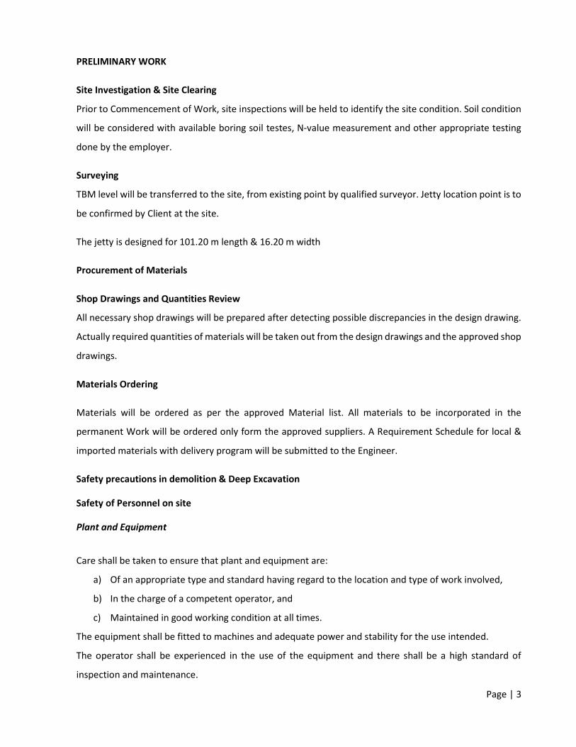
Page | 3
PRELIMINARY WORK
Site Investigation & Site Clearing
Prior to Commencement of Work, site inspections will be held to identify the site condition. Soil condition
will be considered with available boring soil testes, N-value measurement and other appropriate testing
done by the employer.
Surveying
TBM level will be transferred to the site, from existing point by qualified surveyor. Jetty location point is to
be confirmed by Client at the site.
The jetty is designed for 101.20 m length & 16.20 m width
Procurement of Materials
Shop Drawings and Quantities Review
All necessary shop drawings will be prepared after detecting possible discrepancies in the design drawing.
Actually required quantities of materials will be taken out from the design drawings and the approved shop
drawings.
Materials Ordering
Materials will be ordered as per the approved Material list. All materials to be incorporated in the
permanent Work will be ordered only form the approved suppliers. A Requirement Schedule for local &
imported materials with delivery program will be submitted to the Engineer.
Safety precautions in demolition & Deep Excavation
Safety of Personnel on site
Plant and Equipment
Care shall be taken to ensure that plant and equipment are:
a) Of an appropriate type and standard having regard to the location and type of work involved,
b) In the charge of a competent operator, and
c) Maintained in good working condition at all times.
The equipment shall be fitted to machines and adequate power and stability for the use intended.
The operator shall be experienced in the use of the equipment and there shall be a high standard of
inspection and maintenance.

Page | 4
Where appropriate, plant and equipment shall comply with the requirements of the relevant British
Standards or other approved international standard.
Protection of Site personnel
During the construction work all operators and workers shall wear adequate protective clothing and, where
appropriate, protective equipment such as safety helmets, goggles, ear defenders and respirators.
Other Precautions Every working place and approach and all openings dangerous to persons employed and others shall be
properly illuminated and protected.
Before carrying out any part of construction, contractor shall consider prevailing weather conditions and
weather forecast. Particular attention shall be paid to the effects of adverse wave movements.
When entering into confined spaces effective steps shall be taken to establish and maintain an atmosphere
fit for respiration. Standby men may be necessary during such operations as may be the provision, and
training in the use, of rescue equipment.
Fire or Explosion Risks Precaution shall be taken to prevent the risk of fire or explosion caused by gas or vapor. When thermal
reaction or thermal lancing methods are used, consideration shall be given to the prevention or oxygen
enrichment and the attendant risk of explosion or liquefied petroleum gas shall be handled with care and
stored and used in accordance with good practice.
The use of thermal cutting tools in close proximity to timber and other flammable materials shall be
avoided unless suitable precautions are taken against the risk of fire or explosion.
Explosives shall be handed and used in accordance with the recommendations given in BS 5607.
Piling
Cast in Bored piles
BORED PILING
1. General
The method statement for bored piling below describes the whole construction procedures including material and equipment required for the construction of bored cast-in-situ piles
Detail of the procedures contained herein may be reviewed periodically and modified based on actual requirement

Page | 5
The piles to be constructed will be of a nominal specified diameter, bored through overlying soils to found in the bedrock strata or remain in the soil to act as shaft friction and end bearing piles.
The piles are designed by the Engineer to resist axial compressive loads.
2. BORED PILES CONSTRUCTION
The pile boring operations shall be performed using the suitable rotary drill rigs depends on the diameter, depth, and soil condition and construction method. 84 Nos of Piles are designed for construction in 600 mm diameter with 5.0 m center to center intervals.
The bore-holes shall be stabilized with a temporary steel casing in 15 mm thickness steel plates.
The length of the casing will be determined from the actual soil condition encountered on site.
Bentonite shall be used for unstable subsoil condition and for piles equal and more than 1800 mm diameter.
3. SETTING OUT
The location of permanent bored piles shall be set out and by the contractor’s surveyor based on approved setting out drawings from consultant and control points at site
The surveying details of each location to be recorded incorporating reduced level and coordinates.
Each individually surveyed pile position shall be protected from disturbance prior to commencement of boring works.
Two reference points to be installed equidistant at not less than 2.0m from the pile center location.
A pilot hole of about 3 - 6 meter deep shall be drilled at the pile location.
f. The eccentricity and alignment of the pilot hole is then checked.
4. DRILLING
Prior to commencing any operations, the client representative will be required to verify all associated technical information such as presence of services, pile coordinates, platform and cut-off levels, validity of drawings etc.
Then, if necessary, after accurately setting out of the pile location by a land surveyor, a temporary casing will be set in position with length of casing to be determined from ground condition.
The vertical accuracy of the casing will be checked during the installation process using 2 numbers of plumb bob.

Page | 6
Excavation of the soil inside the casing/bored holes will be carried out using the rotary Kelly bar and the auger or bucket method.
The drilling process will be continued to the designed founding depth or to the commencement of rock head level by using augers and drilling buckets.
Pile lengths shall be as per the current construction drawings or as otherwise instructed by the client/Engineer.
At the point of encountering the rock head level, for examples, where the soil drilling tools are unable to penetrate the strata any further, boring shall cease in order that the client’s representative may verify the occurrence and confirm the rock socketing criteria.
For drilling through rock, rock drilling tools shall be applied. This shall include rock auger, core barrels, (round shank, roller bit) cross cutters and where necessary, chisels.
The final toe level of the pile shall be verified by the client’s representative. A detailed record of all encountered ground conditions together with the associated times and type of equipment and materials used will be recorded in the ‘Pile Bore Log’.
Upon reaching the final depth, loose and remolded material and debris will be removed using ‘cleaning bucket’. The cleaning bucket is a specially design flat bottom bucket which will pick up all the loose material at the bottom of the hole. The base of the hole shall be checked by the measuring the depth of the base.
5. BENTONITE
The bentonite is delivered to site in 50kg per bags, which are stored under cover.
The bentonite is mixed by high turbulence mixers and the slurry is stored in a pool. The size of the pool shall have a storage capacity of about 400 cu. m.
A laboratory is provided on site for regular testing of the slurry.
The minimum frequency of testing and the acceptable range of physical characteristics of the bentonite slurry must be conforming to specification.
Laboratory reports are kept during the construction period.
Apparatus available in the site laboratory includes the following: 1 mud balance (density test) 1 marsh cone (viscosity test) 1 sand screen set (sand content test) Paper for measuring Ph
Contaminated bentonite slurry will be discarded by mixing with the earth and transport to dumping area.
Bentonite will be used as a drilling fluid to stabilize the bored hole.
During the boring process, the bentonite slurry is kept as high as possible within the casing and well above the existing ground water

Page | 7
Upon completion of boring, the bottom of the bored hole is thoroughly cleaned with the cleaning bucket prior to recycling of the bentonite
A submersible turbine pump attached to the tremie pipe is lowered to the bottom of the bored hole.
The bentonite, loaded with soil particles in suspension, is drawn off from the bottom of the bored hole and recycled through a Caviem or equivalent recycling unit.
The process is continued until the bentonite arriving from the base of bored hole had been flush out.
6. INSTALLATION OF STEEL CAGE
The reinforcement cage will be fabricated in lay-down sections.
The length, type and size of the steel cage will be according to contract drawings and specifications.
The cages will be provided with stiffening rings and others accessories to enable handling, lifting and installation without permanent deformations.
Cages will be installed into the bored hole using a service crane of the required lifting capacity
Concrete spacers wired to the cage shall provide lateral support and ensure adequate concrete cover.
Spacers shall be placed at 3 equal levels of each 12m cage with 3 nos at each level.
If the diameter of bored pile more than 200cm the spacers shall be placed more than 3 nos to be advised by consultant representative.
7. CONCRETING
All pile shall then be concreted by using the (tremie) method.
Concrete of higher slump (=175mm+25mm) otherwise specified, shall be used for ‘tremie’ method.
The self-compacting mixed concrete will be discharged through a tremie pipe, which is lowered centrally to the bottom of the bored hole prior to filling it with concrete.
Concrete level of the borehole was recorded after each concrete truck discharged and graph will be plotting against theoretical.
One length shall be continuously embedded in the concrete during this process to ensure that the discharge of concrete is below the level of the impurities, which might be present in the top part of the rising head of concrete.
All testing and sampling of the concrete shall be carried out as instructed by the Engineer or Engineer’s representative.

Page | 8
A complete record of all cubes taken shall be maintained in a proper form and slump test results shall be recorded on the ‘Delivery Order’ and the ‘Pile Bore Log’.
All compressive concrete tests will be carried out at the supplier’s laboratory and independent lab.
The client will be notified of the dates of the test by regular issuance in order the tests maybe witnessed.
For a continuous assurance of concrete quality and integrity, concrete will be poured to minimum 0.6m above the theoretical cut-off level (Otherwise Specified).
All completed piles shall be temporarily barricaded and to be backfilled to ground level with a suitable material the next day.
8. SPOIL REMOVAL
Spoil from piles will be cleared from the boring locations by means of an excavator as boring proceeds.
Depending on the volume of spoil excavated, it will be removed to stockpile area or spoil pit, for drying before loading and removed off-site.
CONCRETE WORK
Supply of Concrete
As per Requirement, Concrete will be supplied from approved concrete batching plants. Trail mix will be get approved before order the materials. Slump test and Concrete Test cubes will be cast in each batching.
Grade 30 Concrete
The mixing design will be submitted for approval from the consultant.
Plywood
Phonic – resin bounded plywood shall be used as it is completely water proof and does not laminate as
does ordinary plywood. Plywood panels shall be formed with timber and nailed with short, thin nails at 150
to 225mm centers.
6 or 10 mm thick plywood shall be given a solid a backing nailed at 100 to 150mm spacing along the four
edges and with at least one nail every 0.1 square meter throughout the surface. The edged of sheets shall
be tacked to the same backing board to ensure the production of a smooth joint.

Page | 9
10 and 16 mm thick plywood shall be nailed to a skeleton backing of dressed timber before fixing to the
studding. 19 mm thick plywood shall be nailed direct to studs at a maximum recommended spacing of
450mm. For spacing greater than 450mm skeleton backing of appropriate design shall be used.
Steel
The reinforcement shall be from an approved manufacturer. All the corrosions will be wire brushed prior
to the use. Only reinforcements with sufficient strength shall be use. Reinforcements shall be cut and /or
bend correctly and accordingly to the requirements following BS 4466 standards. Preferably bars of full
length will be use, whenever necessary lapping will be done according to the engineer’s approval. Binding
shall be done with two standards of annealed steel wire 0.9 -1.6mm thickness. Proper cover blocks or
spacer will be use prior to the concreting.
Formwork
All formworks are fabricated with Plywood sheets in varied thickness as per the location. Plywood sheets
are supported with 2” x 4” Timber as required. GI Pipes, acrow prop will be supported to formwork.
Formwork will be arranged for Pile Caps, Tie Beam and deck slab by using 12 – 15 mm thick plywood sheets
as per shown details.
Construction of Pile Caps & Plinth Beams
After completion and testing of piles, pile caps will be cast along with the Tie Beams and Deck Slab.
Supports to Formwork –
From the internal side of the shaft, GI pipes will be tight in each form sets, with vertical supported pipes. In outer side of the shaft, steel chains and curved shape re-bars will be tight. Pouring Concrete
G 30 Ready mixed concrete will be poured by using pump car, with the maximum height of 2500 mm with proper vibrating.
Construction of Platform
Formwork will be arranged with 12 mm thick Plywood sheet with the circular beam, cross beams and circular platform. Platform formwork will be connected with wall shaft formwork set under platform.

Page | 10
Pouring concrete in Platforms
Each level of platform and beams will be poured concrete with bottom level of wall shaft.
.
Placing of Concrete
The concrete shall be transported from the mixer with the possible delay in liquid tight containers or
barrows and by methods which prevent the segregation or loss of ingredients. Slump loss in transit shall
not exceed 25mm Compensation for excessive slump loss by slowing wetter consistency at the mixer
resulting in shall be primed by washing with rich cement grout before use. These shall be thoroughly
washed and cleaned immediately after stopping concreting. Maximum drop shall be maintain up to a
maximum level of 2.4 m. Required tests such as slump tests and cube test will be done prior to the
concreting.
A record shall be kept of the time and date of all concrete pours and the subsequent removal of formwork.
Concreting shall be commenced only after the officer-in-charge has inspected the formwork and
reinforcement as placed and passed the same.
Shuttering shall be cleaned of all shavings, saw dust, pieces of wood, or other foreign material by the use
of air and water pressure hoses. All accumulation of water or debris shall be flushed out through the holes
or opening provided for the purpose. These holes shall be neatly plugged before concreting.
The full depth of fresh concrete shall be completed without damaging adjacent partly hardened concrete.
Concrete shall be considered as properly compacted when the air bubbles cease to appear on the upper
surface and mortar fills the spaces between the coarse aggregate and begins to cream up to form an even
surface.
When this condition has been attained, the vibrator shall be stopped if using vibrating tables or external
vibrators, while needle vibrators shall be withdrawn slowly so as to prevent formation of loose pockets. In
case both internal and external vibrators are being used, the internal vibrators shall first be withdrawn
slowly after which the external vibrators shall be stopped so that no loose pocket is left in the body of the
concrete. The specific instructions of the makers of the particular type of vibrator used shall be strictly
complied with. Over vibration shall be avoided. Shaking of reinforcement for the purpose of compaction
shall be resorted to Likewise; all precautions shall be taken to prevent displacement of the reinforcement
during the placing and compaction of concrete.

Page | 11
Curing
After the concrete has begun to harden i.e. about 1 to 2 hours after its laying, it shall be protected from
quick drying with moist gunny bags, sand or any other suitable material approved by the officer-in-charge.
After 24 hours of laying of concrete, the surface shall be cured by flooding with water of minimum 25mm
depth, or by covering with wet absorbent materials, e.g. damp hessian or jute, coconut or straw matting,
or a layer of sand about 50mm thick. The curing shall be done for a minimum period of 7 days.
SAFETY, ENVIRONMENT CARE AND PUBLIC RELATION
Signboards will be erected and maintained continuously in excavated areas.
Adequate lighting, warning signals and luminous barricades will be provided throughout the night until
backfilling is completed.
During the continuation of the whole working period, officers with relevant experiences will be dispatched
for 24-hour stand by to cope with emergent situation. First- aid kits and Emergency Tel Numbers will be
kept at site officer all the time. In case of emergency, Special Emergency Team, Safely Officer and Site
Manager will be informed and brought to the site to handle the problem promptly.
Plant, machinery, equipment and hand tools
General provisions Plant, machinery and equipment, including hand tools, both manual and power-driven, shall:
a) Be of good design and construction, taking into account, as far as possible, health and safety and ergonomic principles:
b) Be maintained in good working order c) Be used only for work for which they have been designed unless a use outside the initial design
purpose has been assessed by a competent person who has concluded that such use is safe; d) Be operated only by workers who have been authorized and given appropriate training: e) Be provided with protective guards, shields, or other devices as required by national laws or
regulations. Adequate instructions for safe use shall be provided where appropriate by the manufacturer or
the employer, in a form understood by the user As far as practicable, safe operating procedures shall be established and used for all plant,
machinery and equipment. Operators of plant, machinery and equipment shall not be distracted while work is in progress. Plant machinery and equipment shall be switched off when not in use and isolated before any
major adjustment, cleaning or maintenance is done. Where trailing cables or hose pipes are used they shall be kept as short as practicable and not
allowed to create a safety hazard.

Page | 12
All dangerous moving parts of machinery and equipment shall be enclosed or adequately guarded in accordance with national laws and regulations.
Every power-driven machine and equipment shall be provided with adequate means, immediately accessible and readily identifiable to the operator, of stopping it quickly and presenting it from being started again inadvertently.
The machines or equipment shall be so designed or fitted with a device that the maximum safe speeds, which shall be indicated on it. Is not exceeded; if the speed of the machine is variable, it shall only be possible to start it at the lowest speed appropriate.
Operators of plant, machinery, equipment and tools shall be provided with personal protective equipment including, where necessary, Suitable hearing protection.
Hand tools Hand tools and implements shall be tempered, dressed and repaired by competent persons. The cutting edges of cutting tools shall be kept Heads of hammers and other shock tools shall be dressed or ground to a suitable radius on the
edge as soon as they begin to mushroom or crack. When not in use and while being carried or transported sharp tools shall be kept in sheaths, shields,
chests or other suitable containers. Only insulated or non-conducting tools shall be used on or near live electrical installations if there
is any risk of electrical shock. Only non-sparking tools shall be used near or in the presence of flammable or explosive dusts or
vapors.
Electrical tools Portable electrical tools shall generally be used on reduced voltage to avoid as far as possible the
risk of a lethal shock. All electrical tools shall be earthed, unless they are “all insulated” or “double insulated” tools which
do not require an earth. Earthlings shall be incorporated in metallic cases and as a safeguard against damaged cables where wires enter the tool.
All electrical tools shall receive inspection and maintenance on a regular basis by a competent electrician, and complete records kept.
Woodworking machines Shavings, sawdust, Etc, shall not be removed by hand from woodworking machines or in their
vicinity while the machines are working. On hand saws all the blades, except the operating portion, shall be enclosed. Band wheels shall be
enclosed with stout guards. Band saws shall be provided with automatic tension regulators. Planning machines shall be provided with bridge guards covering the full length and breadth of the
cutting block and easily adjustable in both horizontal and vertical directions. Thickness machines shall be provided with sectional feed rollers or a kick-back preventer which
shall be kept as free as possible.

Page | 13
Woodworking machines shall be properly spaced to avoid accidental injury when handling large boards or long planks.
Where provided. Chip and sawdust extraction s stems shall be maintained in efficient working order.
Mechanical feeding devices shall be used when ever practicable. All cutters and saw blades shall be enclosed as far as practicable Circular saws shall be provided with strong, rigid and easily adjustable guards for the saw blades
and with riving knives of suitable design matched to the saw blade in use. The width of the opening in the table for the saw blade shall be as small as practicable.
Portable circular saws shall be so designed that when the blade is running idle it is automatically covered.
Concrete work equipment Concrete mixers shall be protected by side railings to prevent workers from passing under the skip
while it is raised. Hoppers into which a person could fall, and revolving blades of trough or batch-type mixers, shall
be adequately guarded by grating. In addition to the operating brake, skips of concrete mixers shall be provided with a device or
devices by which they can be securely blocked when raised. While the drum of a concrete mixer is being cleaned, adequate precautions shall be taken to
protect the workers inside by locking switches open, removing fuses or otherwise cutting off the power.
Concrete buckets for use with cranes and aerial cableways shall be free as far as practicable from projections from which accumulations of concrete could fall.
Loaded concrete buckets shall be guided into position by appropriate means. Concrete buckets positioned by crane or aerial cableways shall be suspended by safety hooks. When concrete is being tipped from buckets, workers shall keep out of range of any kick-back due
to concrete sticking to the bucket. Concrete bucket towers and masts with pouring gutters or conveyor belts shall:
a) Be erected by competent persons; b) Be inspected daily.
The winch for hoisting the bucket shall be so placed that the operator can see the filling, Hoisting, emptying
Where practicable, be provided with an adequate means indicating its position. Guides for the bucket shall be correctly aligned and so maintained as to prevent the bucket from
jamming in the tower. Scaffolding carrying a pipe for pumped concrete shall be strong enough to support the pipe when
filled and all the workers who may be on the scaffold at the same time, with a safety factor of at least 4.
Pipes for carrying pumped concrete shall: a) Be securely anchored at the ends and at curves: b) Be provided near the top with air release valves; c) Be securely attached to the pump nozzle by a bolted collar or equivalent means.

13-87
Appendix 6 Water quality test results from MWSC

MWSC-A5-F-92 Rev 00
WATER QUALITY TEST REPORTReport No: 500184675
Sample Description ~ Thi T2 Thi T3
Sample Type ~ Sea Water Sea Water
Sample No 83212697 83212698
Sampled Date ~ 05/06/2020 05/06/2020 TEST METHOD UNIT
PARAMETER ANALYSIS RESULT
Physical Appearance Clear with particles Clear with particles
Turbidity 0.191 0.155 HACH Nephelometric Method (adapted from HACH 2100N Turbidimeter User Manual) NTU
Keys: NTU : Nephelometric Turbidity Unit
Notes: Sampling Authority: Sampling was not done by MWSC Laboratory This report shall not be reproduced except in full, without written approval of MWSC This test report is ONLY FOR THE SAMPLES TESTED. ~ Information provided by the customer
************************* END OF REPORT *************************
Page 1 of 1
Male' Water & Sewerage Company Pvt LtdWater Quality Assurance LaboratoryQuality Assurance Building, 1st Floor, Male' Hingun, Vilimale', Male' City, MaldivesTel: +9603323209, Fax: +9603324306, Email: [email protected]
Customer Information:Land & Marine Environment Resources H.Azum Ameeneemagu Male' MALE
Report date: 02/07/2020Test Requisition Form No: 900190152Sample(s) Recieved Date: 01/07/2020
Date of Analysis: 01/07/2020 - 01/07/2020
Checked by
Aminath Sofa Laboratory Executive
Approved by
Mohamed Eyman Manager, Quality

13-88
Appendix 7 Bathymetric survey of project area

-40m
-40m
-40m
-38m
-38m
-38m
-36m
-36m
-36m
-34m
-34m
-34m
-34m
-34m
-32m
-32m
-32m
-32m
-30m
-30m
-30m
-30m
-28m
-28m
-28m
-26m
-26m
-26m
-24m
-24m
-24m
-22m
-22m
-22m
-20m
-20m
-20m
-18m
-18m
-18m
-18m
-16m
-16m
-16m
-16m
-14m
-14m
-14m
-12m
-12m
-12m
-10m
-10m
-10m
-10m
-8m
-8m
-8m
-6m
-6m
-6m
-6m
-5m
-5m
-5m
-5m
-5m
-4.8m
-4.8m
-4.8m
-4.8m
-4.8m
-4.6m
-4.6m
-4.6m
-4.6m
-4.4m
-4.4m
-4.4m
-4.4m
-4.4m
-4.2m
-4.2m
-4.2m
-4.2m
-4.2m
-4.2m-4.2m
-4m
-4m
-4m
-4m
-4m
-4m
-4m
-4m
-4m
-3.8m
-3.8m
-3.8m
-3.8m
-3.8m
-3.8m
-3.8m
-3.8m
-3.8m
-3.6m
-3.6m
-3.6m
-3.6m
-3.6m
-3.6m
-3.6m
-3.6m
-3.6m
-3.4m
-3.4m
-3.4m
-3.4m
-3.4m
-3.4m
-3.2m
-3.2m
-3.2m
-3.2m
-3.2m
-3.2m
-3.2m
-3m
-3m
-3m
-3m
-3m
-2.8m
-2.8m
-2.8m
-2.8m
-2.8m
-2.8m
-2.8m
-2.6m
-2.6m
-2.6m
-2.6m
-2.6m
-2.6m
-2.4m
-2.4m
-2.4m
-2.4m
-2.4m
-2.2m
-2.2m
-2.2m
-2.2m
-2m
-2m
-1.8m
-1.8m
-1.8m
-1.6m
-1.6m
-1.4m
1.7421.744
1.7701.772
1.245
1.219
1.2741.268 0.6630.680
0.8120.823
10m 20m 50m
Geodetic Parameter : Zone : UTM Zone 43 Spheroid : WGS 1984 Vertical Datum : MEAN SEA LEVEL
0m

13-89
Appendix 8 List of participants of Scoping meeting

Environmental Protection AgencyMale', Rep of Maldives
Anshurfu /'t")tel ,y' t+'fr"/aL:htMeeting: l/rN7s;z'/o ?et//
^", or/,r/ro) t (su*laf )Time:19:66
MEETING ATTENDANCE
Name Designation Office Emai! Signatqlre01 k fur^-- DDv--{rt- /y) eL_ ?A*,1{-ia"*"-/1" '('uftf,q ?Q02 tl
- /.
l-lttg,tr< lollttl- fln Crutj*4 I*t"(ar6r4 h osa n'z/^.rg[ a ^* r r*' * / I?*o03 .lawA Mhuuq t fuNtq o{ qMl2 L ahwA.nthu&Y @fl^ ,&tffifrvt ; O(l^'+ko4
At'^r; A*"', "$qr^h Ct,,k wtft(-^l^yyrd
q\nq.tOq*,+t -an,$tsffi\ \d05
DWt1,(- Mtzry Qwtqb <U (h4€L tsmoi l. nru, "lQ L^r,)/-, *
I1165v-rl
06rn, l-h,rn."t( () rt&n ln It t_ m 6ot^*il*rt/rar,h, H.+z+ esa,fulJ_
07 lvror-*.^-e(5 tf*'--r?*--e--\ (
*FZ*;sl*< .
9[(a z&or e?i Com * t 7o czeo(08 ?f*lt^'^ Alil cc I trS I f .^[ Aa"t^u41c,t Vh-; .
e, BteYUQ'o' ?f4 ,,^agv,iv ,^n l.d A 4^ W *8h*L ryt09 I
10
Phone No.
///;l.