alpha - combimaxletsfixit.co.uk/wp-content/uploads/combimax600.pdf · instructions leave these...
TRANSCRIPT

Installation and ServicingInstructions
Leave these instructions with the User
Alpha CombiMax 350 and 600Unvented Hot Water Store
for use with theAlpha 240/280 Range of Gas Fired Combination Boilers
Goldsel Road,Swanley, Kent BR8 8EX
Fax: (01322) 615017
For Technical help or for Service call ...ALPHA HELPLINETel: (01322) 669443
Building Regulations
Certificate No. ETC 03198
These instructions must be used in conjunction with the Installation instructions providedwith the selected combination boiler.

2 Alpha CombiMax 350 and 600
CONTENTS
1 Introduction ....................................... 2
2 Technical data ................................... 3
3 Installation information ....................... 5
4 Installation ......................................... 7
5 Commissioning ................................. 11
6 Operation .......................................... 13
7 Routine servicing ............................... 13
8 Component replacement ................... 14
9 Wiring diagrams ................................ 16
10 Short parts list ................................... 17
11 Fault finding ...................................... 17
12 Appendix 1 (remote location) ............. 18
The CombiMax is a wall mounted unvented secondary hot water storage cylinder for use with the Alpha 240/280 range of gasfired combination boilers.
Two models are available - the CombiMax 350 with a 35 litre capacity and the CombiMax 600 with a 60 litre capacity.
The store is supplied with a pump, thermostats, pressure reducing valve, check valve, expansion vessel, expansion reliefvalve, temperature/pressure relief valve and tundish. It is also supplied with all the required fittings and pipework to enableconnection to the selected Alpha combination boiler.
The CombiMax provides hot water at temperatures of up to 56°C at flow rates of up to 18 l/min (4 gal/min).Note: To enable this flow rate to be achieved:-
1.The cold water mains supply must be able to deliver 22 l/min to the appliance.2.Pipework to the hot water outlets should be as short as is practical and have minimal pressure loss.
The CombiMax can be converted to enable a secondary circulation loop to be connected to it, thus supplying domestic hotwater immediately a hot water tap is opened. The CombiMax pump is used to circulate the hot water within the loop. For fulldetails contact Alpha Therm Ltd.
The CombiMax storage cylinder has the facility for fitting an electric immersion heater (which must be obtained from AlphaTherm Ltd.) and an external clock for timing the domestic hot water operation.
IMPORTANT
This appliance has been approved to the Building Regulations for unvented hot water storage systems and the Local Authoritymust be notified of the intention to install. Therefore the installation must be carried out by a person competent to installunvented hot water systems in accordance with the following recommendations:-
All relevant Building Regulations issued by the Department of the Environment
Building Standards (Scotland) (Consolidation) Regulations issued by the Scottish Development Department
Local Water Bye Laws
Health & Safety Document No. 635 (The Electricity At Work Regulations 1989)
The installation should also be in accordance with the following British Standard Codes of Practice:-BS 5546:1990 Installation of hot water supplies for domestic purposesBS 6700:1987 Design, installation, testing and maintenance of services supplying waterBS 7671:1992 Requirements for electrical installations, IEE Wiring Regulations
Failure to install this appliance correctly could lead to prosecution. It is in your own interest and that of safety to ensure that thelaw is complied with.
Manufacturer's instructions must NOT be taken in anyway as over-riding statutory obligations.
NOTE: Failure to use an Alpha boiler with the CombiMax will invalidate its approval, warranty and may be unsafe.
1 INTRODUCTION

3Alpha CombiMax 350 and 600
2 TECHNICAL DATA
8 bar
0.1 bar
15 mm
15 mm
35 L
60 L
4 L at 2.5 bar
5 L at 2.5 bar
2.5 bar
90°C/7 bar
4 bar
18.0
4.0
56
133
7.25 mins
12 mins
4.0 mins
7 mins
Domestic Hot Water
Max. Mains Inlet Pressure (inlet of pressure reducing valve)
Min. Mains Water Pressure
Mains Inlet Connection
DHW Outlet Connection
DHW Storage (350 model)
(600 model)
Expansion Vessel Size (pre-charge press.)
(350 model)
(600 model)
Pressure Reducing Valve Setting
Temperature and Pressure Relief Valve
Expansion Relief Valve Setting
Flow Rate L/min
G.P.M.
Outlet Water Temp. (Approx.) °C
°F
Time to raise water storage 50°C (350 model)
(600 model)
Reheat time for 70% of storage (350 model)
(600 model)
Min. Clearances required for Servicing
Top
Bottom
Sides
Front
Dimensions CombiMax Height
(350 model) Width
(600 model) Width
Depth
Overall width when fitted with boiler
(350 model)
(600 model)
Lift Weight of Store (350 model)
(600 model)
Weight Full and Operational (350 model)
(CombiMax and Boiler) (600 model)
2.2 INSTALLATION
Supply
External Fuse
Power Consumption
230/240 V ~ 50 Hz
3 A
90 W
2.3 ELECTRICAL
2.1 DOMESTIC HOT WATER
2.4 ELECTRICAL CONNECTIONSNote: This Appliance Must Be Earthed
Boiler terminal block CombiMax terminal block
220 mm
250 mm
5 mm
450 mm
950 mm
270 mm
365 mm
360 mm
720 mm
815 mm
12 kg
25 kg
92 kg
130 kg
Supply
External Fuse
Power Consumption
230/240 V ~ 50 Hz
10 A
2 kW
Alpha Immersion Heater (optional)
4 Alpha CombiMax 350 and 600
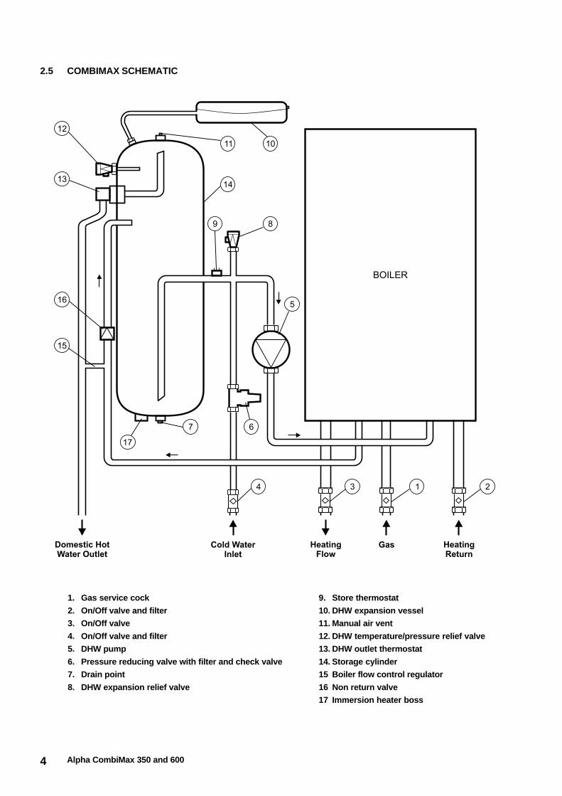
2.5 COMBIMAX SCHEMATIC
1. Gas service cock
2. On/Off valve and filter
3. On/Off valve
4. On/Off valve and filter
5. DHW pump
6. Pressure reducing valve with filter and check valve
7. Drain point
8. DHW expansion relief valve
9. Store thermostat
10. DHW expansion vessel
11. Manual air vent
12. DHW temperature/pressure relief valve
13. DHW outlet thermostat
14. Storage cylinder
15 Boiler flow control regulator
16 Non return valve
17 Immersion heater boss

5Alpha CombiMax 350 and 600
3.1 ELECTRICAL SUPPLY
The CombiMax requires a 230/240 V ~ 50 Hz electrical mains supply.
This appliance must be earthed.
The mains supply to the CombiMax and boiler must be directly connected to the CombiMax terminal block, i.e. not the boiler. Asupply cable from the CombiMax terminal block has been provided for connection to the boiler terminal block.Notes: 1. If an external control is to be fitted, it must be suitable for 240 V and it must be connected to the boiler terminal block.
2. If an external DHW clock is to be fitted, it must be suitable for 240 V and it must be connected to the CombiMaxterminal block.
There must only be one common isolator, providing complete electrical isolation, for the CombiMax, boiler and any external controls.However, if an immersion heater is to be fitted, an independant electrical supply must be provided. Refer to the instructions suppliedwith the Alpha immersion heater kit.
The appliance should be connected to a fused three pin plug and unswitched shuttered socket outlet (both complying with BS 1363),or a fused double pole switch with a contact separation of at least 3 mm in both poles using heat resisting cable (i.e. 85°C) not lessthan 0.75 mm² (24 x 0.2 mm) to BS 6500 Table 9.
Wiring external to the boiler must be in accordance with the current IEE Wiring Regulations (BS 7671).
Note: If an immersion heater is to be fitted, this must be supplied by Alpha Therm Ltd. and be installed as per the instructions suppliedwith the kit. A standard 3 kW immersion heater must not be fitted.
DHW CLOCK - Sometimes it may be required to switch off the CombiMax and, if fitted, the secondary circulation overnight toavoid unnecessary heat loss and operation of the appliance. This can be achieved by connecting an external clock to the 'ExtProg' terminals on the CombiMax terminal block, as shown in section 2.4.Note: When the clock is in an OFF position the CombiMax will not operate, i.e. hot water will only be supplied from the waterleft within the storage cyliner. Therefore the OFF periods should be set at times when hot water will not be required.
If a secondary circulation kit is to be fitted, refer to the instructions supplied with the kit.
3.2 LOCATION
The appliance is not suitable for external installation.
The CombiMax and boiler must be installed on a flat vertical wall which is capable of supporting a weight of approximately 92 kg(350 model) or 130 kg (600 model)..
The CombiMax may be installed in any room or internal space, although particular attention is drawn to the requirements of the current IEEWiring Regulations, and in Scotland, the electrical provisions of the Building Regulations applicable in Scotland, with respect to the installationin a room or internal space containing a bath or shower. Where it is installed in a room containing a bath or shower, it must not be possiblefor a person using the bath or shower to touch any electrical switch or boiler control utilising mains electricity.
The appliance may be installed in a cupboard or compartment, provided it is correctly designed for that purpose and that therequirements of BS 6798 are complied with.
The appliance does not require any air vents for cooling in the room in which it is installed or when installed in a cupboard orcompartment.
If required, the CombiMax (produced after February 1999, i.e. from serial No. A906) may be located remotely (up to 1 metre)from the boiler. Refer to Appendix 1, starting on page 18.
3.3 DOMESTIC HOT WATER SYSTEM
To ensure a hot water flow rate of 18 l/min the mains water supply must be capable of delivering 22 l/min to the appliance at 2 bar.
The incoming mains water pressure is regulated to 2.5 bar within the Combimax by a pressure reducing valve. However, all tapsand mixing valves used with the hot water system must be suitable for operating at a pressure of up to 8 bar.
To ensure economic use, the pipe runs between the appliance and taps should be in 15 mm copper pipe and be as short aspossible. Where possible the pipework should be insulated to reduce heat loss.
Showers - A shower may be used with the CombiMax if required.If a loose or flexible head type shower is used it may require the fitting of a double check valve, to comply with Water Bye Law 17.
Bidets - No anti-syphonage arrangements are necessary, provided the outlets are shrouded and it is not possible to attach a temporaryhand held spray. A supply of direct mains fed hot and cold water is permitted provided the appliance is of the over-rim flushing type.
Before the mains water supply pipe is connected, it should be thoroughly flushed out to avoid the danger of dirt or foreignmatter entering the CombiMax or boiler and the filter incorporated within the pressure reducing valve cleaned.
The stored water temperature is approximately 56°C. In hard water areas this should avoid possible scale build-up. However, ifdescaling is necessary contact Alpha Therm Ltd. for guidance.
3 INSTALLATION INFORMATION

6 Alpha CombiMax 350 and 600
3.4 UNVENTED HOT WATER STORAGE SYSTEM
The installation is subject to Building Regulations approval and the Local Authority must be notified of the intent to install.
The CombiMax store is supplied with the components required for an unvented hot water system, i.e. temperature/pressure andexpansion relief valves, expansion vessel, check valve and tundish. All these components are factory fitted, except for the expansionvessel, which is to be connected to the top of the storage cylinder after installation, and the tundish which must be installed as follows:-
Discharge pipe - The discharge pipes from both the temperature/pressure and expansion relief valves have been joined togetherwithin the appliance. The combined discharge pipe from the appliance must be routed to the tundish supplied in 15 mm pipe.
Tundish - The tundish must be positioned within 500 mm of the appliance, so that it is visible to the User and away from electricaldevices. The minimum size of the discharge pipe downstream of the tundish is given in the following table.
Fig. 1a
300 mmminimum
Tundish
500 mm max.from appliance
Metal discharge pipe (D2) fromtundish with continuous fall
Metal discharge pipe (D1)from relief valves to tundish
Temperature/pressurerelief valve
300 mmminimum
100 mm max.70 mm min.
Gulley ifavailable
Pipe close to wall toallow water to fan outsafely
Ground level
D2
D1
LOW LEVEL TERMINATION
Resistance createdby each elbow
or bend
0.8 m
1.0 m
1.4 m
Maximum resistance allowed,expressed as a length of straight
pipe (i.e. no elbows or bends)
up to 9 m
up to 18 m
up to 27 m
Minimum size of dischargepipe 'D2' from tundish
22 mm
28 mm
35 mm
Minimum size of dischargepipe 'D1' to tundish
15 mm
Valveoutlet size
G½
Sizing of copper discharge pipe 'D2' - refer also to Figs. 1a and 1b
The discharge pipework from the tundish:-a. Shall fall continuously through its length.b. Shall be of a heat resistant material, e.g. metal.c. Shall not be fitted with any valves or taps.d. Shall discharge to a safe visible position, e.g. onto the surface of an external wall or into a gulley.e. Shall have a minimum of 300 mm straight pipework directly from the tundish.
Note: Where children may play or otherwise come into contact with discharges, a wire cage or similar guard must bepositioned to prevent contact whilst maintaining visibility.
Refer to Figs. 1a and 1b for suggested methods of terminating the discharge pipe safely.
Where a single pipe serves a number of discharges, such as in blocks of flats, the number served should be limited to not morethan 6 systems so that any installation can be traced reasonably easily. The single common discharge pipe should be at leastone pipe size larger than the largest individual discharge pipe to be connected.
If the system is installed where discharges from safety devices may not be apparent, i.e. in dwellings occupied by blind, infirm or disabledpeople, consideration should be given to the installation of an electronically operated device to warn when discharge takes place.
7Alpha CombiMax 350 and 600
4.1 UNPACKING
The boiler must be installed before the CombiMax store, so therefore carefully unpack the CombiMax box, check and safelyplace all the components to one side until installation.Note: To avoid damage, do not lift the store via the valves and pipework.
1. The CombiMax is supplied in one box containing the following:-
a. Assembled CombiMax store complete with its casing support brackets, controls and wiring centre.
b. Wall mounting frame.
c. Expansion vessel (4 litre with 350 model and 5 litre with 600 model) with a pre-charge of 2.5 bar and flexible hose.
d. Boiler connecting pipes, together with screws, wall plugs and washers.e. Literature pack and DHW control knob label.
f. Boiler conversion kit with restrictor, spanner and boiler converted label.
2. Unpack the boiler as per the Installation instructions supplied with the boiler.
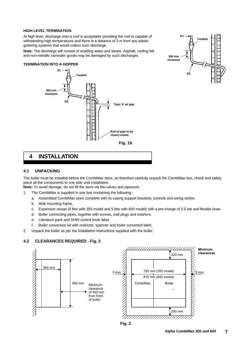
4.2 CLEARANCES REQUIRED - Fig. 2
4 INSTALLATION
Fig. 2
At high level, discharge onto a roof is acceptable providing the roof is capable ofwithstanding high temperatures and there is a distance of 3 m from any plasticguttering systems that would collect such discharge.
Note: The discharge will consist of scalding water and steam. Asphalt, roofing feltand non-metallic rainwater goods may be damaged by such discharges.
HIGH LEVEL TERMINATION
TundishD1
D2
300 mmminimum
D1
D2
300 mmminimum
Tundish
Type 'A' air gap
End of pipe to beclearly visible
Fig. 1b
TERMINATION INTO A HOPPER

8 Alpha CombiMax 350 and 600
4.3 CONVERT THE BOILER FOR FITTING THE COMBIMAX - Figs. 3, 4, 5 and 6
The boiler may be converted before or after mounting it onto thewall as described below.
When mounting the boiler onto the wall follow the installationinstructions supplied with the boiler.Note: Do not connect the pipework, electrical mains supply orfit the flue until the CombiMax has been fitted.
1. Lower the front cover and loosen the two fixing screwssecuring the control panel as shown in Fig. 3.
2. Remove the left hand side panel of the boiler by removingthe top and two bottom screws as shown in Fig. 3.
Fig. 4
4. Modify the differential pressure sensor (see Figs. 5and 6) as follows:-
a. Unscrew fitting 'A' and discard the components A,B and C as shown in Fig. 5.
Fig. 5 - Differential pressure sensor BEFORE modification
b. Screw fitting 'D' (supplied in the conversion kit) intothe sensor body as shown in Fig. 6.
Fig. 6 - Differential pressure sensor AFTER modification
5. Re-assemble the differential pressure sensor into the boiler in reverse order.
Note: After converting the boiler, fit the label supplied in the conversion kit to the inside of the hinged cover so that it can beseen when the cover is lowered.
RestrictorFilter
Differentialpressure sensor
C B A
D
Fig. 3
3. Remove the differential pressure sensor from the boiler usingthe spanner provided as follows:-Disconnect the two flow sensing pipes from the right handmanifold, then unscrew and remove the end fitting containingthe filter/restrictor as shown in Fig. 4.

9Alpha CombiMax 350 and 600
4.4 FIT THE COMBIMAX - Figs. 7 and 8
1. Locate the wall mounting frame over the top left hand panel of the combination boiler to ensure correct alignment.
2. Drill five wall fixing holes (8 mm dia.) through the mounting frame (as shown in Fig. 7) and secure with the screws andplugs provided.
3. Hang the storage cylinder on the mounting frame, ensuring the top and bottom brackets on the store locate on the supportson the frame (see Fig. 7). Pass the plastic security strap around the cylinder and secure in position (see Figs. 7 and 8).
4. Connect the flexible hose to the expansion vessel and locate it in the space above the boiler to the rear, with the connectionto the left as shown in Fig. 8. Connect the expansion vessel hose to the connection on the top left hand side of the store.CombiMax 600 only - Secure the vessel to the right side rear of the boiler frame with the two screws provided.
5. Fit the side support bracket to the boiler in place of the boiler left hand side panel, securing at both top and bottom asshown in Fig. 8 (remove the front screw from the top of the room sealed chamber to secure the top of the bracket).
6. Fit the top support bracket (with two clips) to the top of the side support bracket and fit the bottom support bracket (withfour clips) to the bottom of the side support using the screws provided.
7. Fit the left hand side panel, removed from the boiler, to the CombiMax by hooking the top of the panel over the brown trimof the mounting frame and securing it at the bottom rear of the panel. Secure the panel to the top and bottom supportbrackets using the screws provided.
Fig. 7 Fig. 8
4.5 FIT THE FLUE
Install the flue in accordance with the Installation instructions supplied with the boiler or flue.
4.6 CONNECT THE PIPEWORK - Fig. 9
1. Thoroughly flush out all the water pipework.Note: Ensure that all the plastic caps are removed from the boiler connections.
2. Secure all the valves/fittings between the CombiMax and boiler as shown in Fig. 9. Use the washers supplied and ensurethe necessary fittings face the rear wall. Fit the union bends to the valves.
Notes: a. If soldering to the boiler union bends, ensure the bends are not connected to the valves, otherwise the internalseals may be damaged.
b. Ensure the 22 mm isolating valve with the filter is fitted to the heating return connection as shown in Fig. 9.
c. Fit the pressure relief valve connection before the isolating valves.
3. Connect the system pipework to the boiler.Note: Do not forget that the heating system pressure relief valve discharge pipe must be routed clear of the boiler to adrain in such a manner that it may be seen, but cannot cause injury to persons or property.
4. Connect the discharge pipework from the temperature/pressure relief and expansion relief valves to the tundish supplied.Note: This pipework must be installed as recommended in Unvented Hot Water Storage System, section 3.4.

10 Alpha CombiMax 350 and 600
4.7 CONNECT THE MAINS SUPPLY - Figs. 9, 10 and 11
1. Remove the screws securing the CombiMax terminal block cover. Pass the electrical mains supply cable through thecable clamp on the boiler and route the cable to the CombiMax terminal block as shown in Fig. 10. Connect the cable asfollows:- Brown to L, Blue to N and Green/Yellow to . Ensure correct polarity and that the cable is secured using theclamping bush supplied.Note: Ensure that the length of the earth wire is such that if the supply cable is pulled out of its clamp the live and neutralwires become taut before the earth wire.If an external DHW clock is to be fitted to the CombiMax terminal block, remove the link between terminals L and S/L, see section 2.4.Connect the clock cable to the 'Ext Prog' terminals N, L and S/L ensuring the cable is secured using the clamping bush supplied.If a secondary circulation kit and/or an Alpha immersion heater is fitted, refer to the instructions supplied with the kit.When all connections have been made to the CombiMax terminal block, replace the terminal block cover.
2. Remove the screw securing the terminal block cover from the back of the boiler control box as shown in Fig. 11. Route thecable provided from the CombiMax terminal block to the boiler (see Figs. 9 and 10) and connect to the boiler terminalblock via the grommet as shown in Fig. 11. Refer to section 2.4 for connection details.The boiler main terminal block can be removed by pulling it off the pins to give easy access to the terminals.Do not switch on the electrical supply at this stage.
3. If an external control, i.e. room thermostat or external clock is to be fitted, remove the link between terminals 1 and 2 onthe boiler terminal block. Pass the cable through the cable clamp, through the grommet (cut as necessary) and connect itto terminals 1 and 2, see section 2.4.
4. Replace the boiler terminal block, ensuring it is located correctly on the plastic pins and replace the cover.
5. Ensure that there is sufficient free cable to allow the control panel to be raised and lowered then tighten the cable clamp screws.
6. Leave the control panel open until commissioning procedures have been completed.
7. Carry out electrical system checks - Short circuit, Polarity, Earth continuity and Resistance to earth with a suitable multimeter.
Note: Disconnect the filling loop after fillingthe central heating system.
A - Heating flow (22 mm)B - Hot water outlet (15 mm)C - Gas inlet (22 mm)D - Cold water mains inlet (15 mm)E - Heating return (22 mm)F - Heating pressure relief valve (15 mm)G - Temperature/pressure expansion relief
discharge pipeH - Drain point for DHW storage
Note: Both Heating return and Cold watermains inlet valves contain serviceable filters.
Fig. 9a - CombiMax 350
Fig. 9b - CombiMax 600

11Alpha CombiMax 350 and 600
Fig. 10 Fig. 11
Remove link to connectexternal control
FuseT2A
Terminal blockcover
Cableclamps
From CombiMax
The boiler must be commissioned as described in the Installation instructions supplied with the boiler.
5.1 FILL THE DOMESTIC HOT WATER SYSTEM
Open the mains water inlet valve and allow the CombiMax store and boiler to fill. When filled, open the manual air vent on thetop of the store (refer to schematic diagram in section 2.5) until all the air has been vented. Turn on all the hot water taps andallow water to flow until no air is present. Turn off the taps. Cover all electrical components beneath the CombiMax pump andthen release the pump bleed screw until all the air has been vented. Retighten the screw.
5.2 BOILER CONTROLS - Fig. 12a, 12b or 12c
The domestic hot water thermostat must always be set to the maximum setting. A label has been supplied which must bepositioned over the domestic hot water thermostat knob.
5 COMMISSIONING
Clock(if fitted)
SystemPressureGauge
CentralHeatingThermostat
DomesticHot WaterThermostat( )set at maximum
SelectorSwitch
GasControl
IndicatorNeons
Pilot and BurnerViewing Window
0 THERMOSTAT 0 THERMOSTAT 0 SELECTOR GAS
OFF
bar0 4
3
2
1
Alpha 240P and Alpha 280P
Fig. 12a

12 Alpha CombiMax 350 and 600
Fig. 12b
5.3 INITIAL LIGHTING
When the selector switch is set to (DHW and CH) the boiler will not operate in the central heating mode until theCombiMax store has reached a temperature of approximately 56°C. This will take between seven to twelve minutes from cold.Depending on whether it is a CombiMax 350 or 600.
5.4 CHECK THE BURNER PRESSURESHot water modeThe burner will stay at maximum output for approximately three minutes and then the burner pressure will decrease slowly to itsminimum, until the hot water store reaches a temperature of approximately 56°C.Check the burner pressure and that the burner goes out when the store is satisfied.
Central heating modeThe boiler will not operate in the central heating mode until the CombiMax store is satisfied.
Clock(if fitted)
SystemPressureGauge
CentralHeatingThermostat
DomesticHot WaterThermostat( )set at maximum
SelectorSwitch
BurnerViewing Window
0 THERMOSTAT 0 THERMOSTAT 0 SELECTOR
bar0 4
3
2
1
IndicatorNeons
RedResetButton
WhiteResetButton
RESET
RESET
Alpha 240E and Alpha 280E
Fig. 12c
Alpha 240X
13Alpha CombiMax 350 and 600
Refer to the instructions supplied with the boiler for full details of the operation of the boiler.
The CombiMax will supply hot water provided the selector switch on the boiler is set to either or .Note: The clock (if fitted) only controls the operating times of the central heating, not domestic hot water - DHW is availablecontinuously, unless an external DHW clock has been fitted to the CombiMax.
Domestic hot water supply always takes priority over central heating. If a demand for hot water is required during a central heating period,the boiler will automatically switch to the hot water mode until the demand is satisfied, i.e. storage water is to the required temperature. Thisinterruption in the central heating is only when the demand for hot water is present and should not be noticed by the User.
When there is a demand for hot water (by opening a hot tap or temperature of the stored hot water is below the thermostatsetting) the store pump starts and circulates mains water through the boiler operating the boiler DHW flow switch. The burnerlights and the mains water is heated by the DHW heat exchanger. When the water in the store reaches a temperature ofapproximately 56°C the store thermostat switches the store pump off.
When a hot tap is opened, hot water is supplied from both the store and boiler. When the temperature within the store fallsbelow the outlet thermostat setting, the hot water flow from the store is stopped and hot water is supplied (at a reduced rate)from the boiler only.
5.5 FINAL COMMISSIONINGThoroughly flush out the water pipework and water in the CombiMax store. Clean the filters within the pressure reducing valveand the mains water inlet valve.
5.6 FINAL ASSEMBLYAfter completing the assembly of the boiler, place the CombiMax front casing in position and secure it at the bottom with twoscrews.Note: Ensure the label has been fitted over the domestic hot water thermostat knob, and that it is set at maximum.
5.7 USER INFORMATIONThe User must be advised (and demonstrated if necessary) of the following important points regarding the CombiMax:-
1. Explain the operation of the CombiMax.
2. The domestic hot water thermostat control knob on the boiler must be set and left at maximum.
3. If an immersion heater has been fitted, it must only be switched on if the boiler/CombiMax is not working.
4. Show the User the position of the pressure relief valve discharge pipes and tundish for the heating and DHW systems.
5. Hand the User's instructions to the User.
6. Leave these Installation and Servicing instructions with the User for use on future calls.
6 OPERATION
Note: It is the law that any service work must be carried out by a competent person.
The boiler must be serviced as described in the instructions supplied with the boiler, taking note of the following instructionsregarding the servicing of the CombiMax.
Warning: Before servicing the CombiMax or boiler ensure the electrical and gas supplies have been isolated.
Gain access: Remove the bottom two screws securing the CombiMax front casing and lift the casing up slightly and remove.
1. Inspect and clean, if required, the filter and cartridge in the pressure reducing valve and cartridge in the expansion reliefvalve fitted to the store.
2. Check the charge in the domestic hot water expansion vessel and re-pressurise if necessary.Check the charge only when the pressure in the mains supply is zero.
7 ROUTINE SERVICING

14 Alpha CombiMax 350 and 600
It is the law that any service work must be carried out by a competent person.Warning: Before replacing any boiler components, isolate the electrical supply and close the boiler gas service cock.After replacement of any components, check the operation of the CombiMax. Ensure that all the controls are returned to theiroriginal settings.Refer to the instructions supplied with the boiler for full details on replacement of the boiler components.
8.1 ACCESS
1. To gain access to the CombiMax, remove the bottom two screws securing the CombiMax front casing and lift the casingup slightly and remove.
2. To gain access to the boiler, refer to the instructions supplied with the boiler.
8.2 DRAINING THE COMBIMAX - See CombiMax Schematic illustration
Isolate the electricity supply.Remove the front casing as described in section 8.1. Close the mains water inlet valve. Open any hot tap below the level of the storeand open the manual air vent on top of the store. Allow as much water to drain from the store as possible. To drain the remainingwater from the store, remove the drain plug at the bottom of the store.Note: Some water will remain in the components and care must be taken when removing them.
8.3 DHW PUMP - See CombiMax Schematic illustration
1. Drain the CombiMax as described in section 8.2.
2. Disconnect the pump unions and withdraw the pump. Remove the wiring cover and disconnect the wiring.
3. Connect the wiring to the new pump as follows:-
Brown to L, Blue to N and Green/Yellow to
4. Ensure the pump is set to maximum (III) and re-assemble in reverse order, using new sealing washers.
5. Refill the store (refer to Commissioning, section 5.1).
8.4 DHW OUTLET THERMOSTAT - See CombiMax Schematic illustration
1. Gain access as described in section 8.1. Ensure the electricity supply is isolated.
2. Close the mains water inlet valve and open any hot tap below the level of the store.
3. Unscrew the thermostat retaining cap and withdraw the wax cartridge and spring (it may be necessary to release thecartridge with the aid of a screwdriver).
4. Fit the new thermostat and re-assemble in reverse order.
5. Refill the store (refer to Commissioning, section 5.1).
8.5 STORE THERMOSTAT - See CombiMax Schematic illustration
1. Gain access as described in section 8.1. Ensure the electricity supply is isolated.
2. Cut and remove the plastic cable tie around the plug and disconnect the plug from the thermostat.
3. Remove the two fixing screws and remove the thermostat from the mains water inlet pipe.
4. Fit the new thermostat and re-assemble in reverse order, fitting a new cable tie around the plug and pipework.
8.6 NON RETURN VALVE - See CombiMax Schematic illustration
1. Drain the CombiMax as described in section 8.2.
2. Undo the unions of the pipe containing the non return valve between the store and boiler.
3. Remove the non return valve
4. Re-assemble in reverse order with a new valve and seals.
5. Refill the store (refer to Commissioning, section 5.1).
8.7 DHW TEMPERATURE/PRESSURE RELIEF VALVE - See CombiMax Schematic illustration
1. Partially drain the hot water circuit as described in section 8.2, so that the water in the store is below the relief valveconnection.
2. Remove the outlet thermostat as described in section 8.4.
3. Disconnect the valve pipework unions and remove the valve from the store.
4. Re-assemble in reverse order with a new valve.
5. Refill the store (refer to Commissioning, section 5.1).
8 COMPONENT REPLACEMENT

15Alpha CombiMax 350 and 600
8.8 DHW EXPANSION VESSEL - See Fig. 8
Note: If a top rear flue has been fitted to the boiler, it may be necessary to loosen the flue connections to the boiler so as toraise the height of the flue by approximately 10 mm to allow removal of the expansion vessel.
1. Close the mains water inlet valve and ensure that all hot water taps are closed. Release the pressure from the hot watercircuit by opening and closing a hot tap which is lower than the store.
2. Disconnect the expansion vessel union and for the CombiMax 600 remove the two screws securing the vessel to the rightside rear frame of the boiler.
3. Remove the expansion vessel.
4. Re-assemble in reverse order with a new vessel. Refill and pressurise the hot water circuit by opening the mains waterinlet valve.
8.9 DHW EXPANSION RELIEF VALVE - See CombiMax Schematic illustration
1. Drain the CombiMax as described in section 8.2.
2. Disconnect the valve pipework unions and remove the valve.
3. Re-assemble in reverse order with a new valve.
4. Refill the store (refer to Commissioning, section 5.1).
8.10 PRESSURE REDUCING VALVE FILTER/CARTRIDGE - See CombiMax Schematic illustration
1. Close the mains water inlet valve and ensure that all hot water taps are closed. Release the pressure from the hot watercircuit by opening and closing a hot tap which is lower than the store.
2. Unscrew the cartridge from the valve body.
3. Clean or replace the filter/cartridge and re-assemble in reverse order.
4 Refill and pressurise the hot water circuit by opening the mains water inlet valve.
8.11 PRESSURE REDUCING VALVE/CHECK VALVE - See CombiMax Schematic illustration
1. Drain the CombiMax as described in section 8.2.
2. Disconnect the unions of the pipe between the water mains inlet valve and pressure reducing valve, and remove the pipefrom the manifold plate.
3. Remove the pressure reducing valve/check valve.
4. Re-assemble in reverse order with a new valve.
5. Refill the store (refer to Commissioning, section 5.1).
8.12 BOILER FLOW CONTROL REGULATOR - See Fig. 9
1. Drain the CombiMax as described in section 8.2.
2. Refer to Fig. 9 and disconnect the pipework containing the regulator.
3. Remove the regulator.
4. Re-assemble in reverse order with a new regulator.
5. Refill the store (refer to Commissioning, section 5.1).
8.13 DHW STORAGE CYLINDER - See CombiMax Schematic illustration
1. Drain the CombiMax as described in section 8.2.
2. Disconnect the DHW expansion vessel connection to the cylinder.
3. Remove the DHW outlet thermostat as described in section 8.4.
4. Remove the DHW temperature/pressure relief valve as described in section 8.6.
5. Remove the DHW expansion relief valve as described in section 8.8.
6. Remove the DHW pump as described in section 8.3.
7. Remove the pressure reducing valve as described in section 8.10.
8. Remove the store thermostat as described in section 8.5.
9. Disconnect all the pipework from the cylinder.
10. Cut and release the plastic security strap and lift the cylinder upwards to disengage it from the mounting frame. Pull thecylinder forward and remove it.
11. Re-assemble in reverse order with a new cylinder, using new seals and new plastic security strap supplied.
12. Refill the store (refer to Commissioning, section 5.1).

16 Alpha CombiMax 350 and 600
9 WIRING DIAGRAMS
9.1 COMBIMAX ILLUSTRATED WIRING DIAGRAM
9.2 COMBIMAX FUNCTIONAL FLOW WIRING DIAGRAM
17Alpha CombiMax 350 and 600
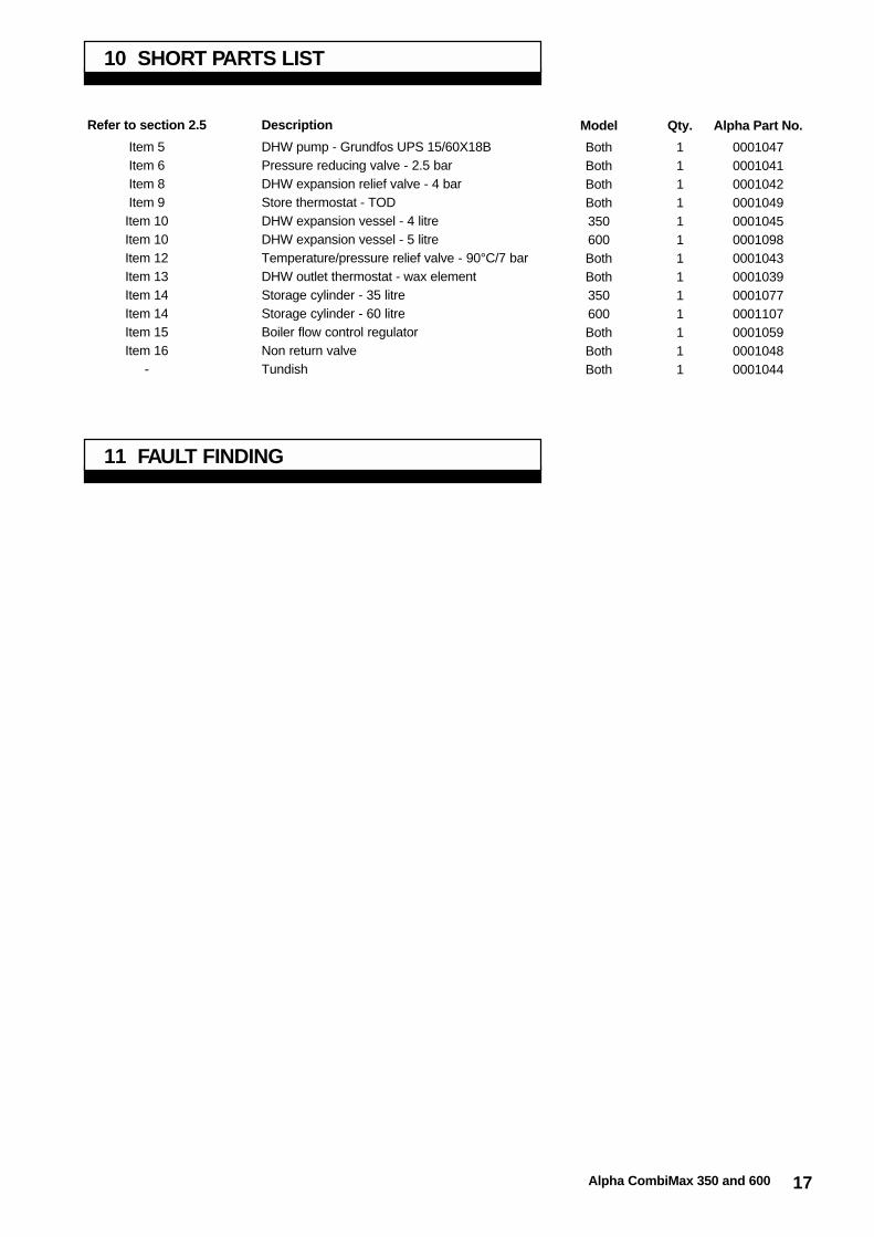
10 SHORT PARTS LIST
Refer to section 2.5
Item 5Item 6Item 8Item 9
Item 10Item 10Item 12Item 13Item 14Item 14Item 15Item 16
-
Description
DHW pump - Grundfos UPS 15/60X18BPressure reducing valve - 2.5 barDHW expansion relief valve - 4 barStore thermostat - TODDHW expansion vessel - 4 litreDHW expansion vessel - 5 litreTemperature/pressure relief valve - 90°C/7 barDHW outlet thermostat - wax elementStorage cylinder - 35 litreStorage cylinder - 60 litreBoiler flow control regulatorNon return valveTundish
Qty.
1111111111111
Alpha Part No.
0001047000104100010420001049000104500010980001043000103900010770001107000105900010480001044
Model
BothBothBothBoth350600BothBoth350600BothBothBoth
11 FAULT FINDING

18 Alpha CombiMax 350 and 600
12 APPENDIX 1
The Alpha CombiMax has been designed to fit onto the left hand side of anAlpha 240/280 boiler. However, it is now possible (using a CombiMax 350 or600 produced after February 1999, i.e. from Serial No. A906) to install it upto a distance of 1 metre from the boiler in the positions shown in Fig. 13.
The pipework between the boiler and CombiMax must be kept as short aspossible and be no more than 1 metres in length, with the number of bendskept to a minimum.
Notes: 1. A CombiMax produced before February 1999, i.e. before SerialNo. A906 must not be fitted remote from the boiler.
2. A CombiMax fitted remote has no casing.
Fig. 13
Possible locationsfor the CombiMax inrelation to the boiler.
Fig. 14
12.2 COMBIMAX SCHEMATIC - remote location from boiler
1. Gas service cock2. On/Off valve and filter3. On/Off valve4. On/Off valve and filter5. DHW pump6. Pressure reducing valve with filter and check valve7. Drain point8. DHW expansion relief valve9. Store thermostat
10. DHW expansion vessel11. Manual air vent12. DHW temperature/pressure relief valve13. DHW outlet thermostat14. Storage cylinder15. Boiler flow control regulator16. Non return valve17. Immersion heater boss
12.1 INTRODUCTION

19Alpha CombiMax 350 and 600
Fig. 15
12.3 INSTALLATION
If the CombiMax is to be fitted in a remote location from the boiler, it should be installed as described in section 4, together withthe following important points:-
12.4 MINIMUM CLEARANCES REQUIRED
12.5 WALL MOUNTINGThe wall mounting frame and security strap supplied, are to be used to secure the CombiMax storage cylinder to the wall.
12.6 CASINGThe casing components supplied with the CombiMax cannot be used when it is fitted in a remote location from the boiler.
12.7 DHW EXPANSION VESSELFit the expansion vessel near the top of the storage cylinder using the flexible hose supplied. See Fig. 15.

Manual compiled and designed by Publications 2000, Tel (01670) 356211
Alpha Therm Limited.Goldsel Road, Swanley, Kent BR8 8EXTel: (01322) 669443Fax: (01322) 615017
Part No. 0001056/4
These instructions have been carefully prepared but we reserve the right toalter the specification at any time in the interest of product improvement.© Alpha Therm Limited 1999.
11/99/D112
Fig. 16
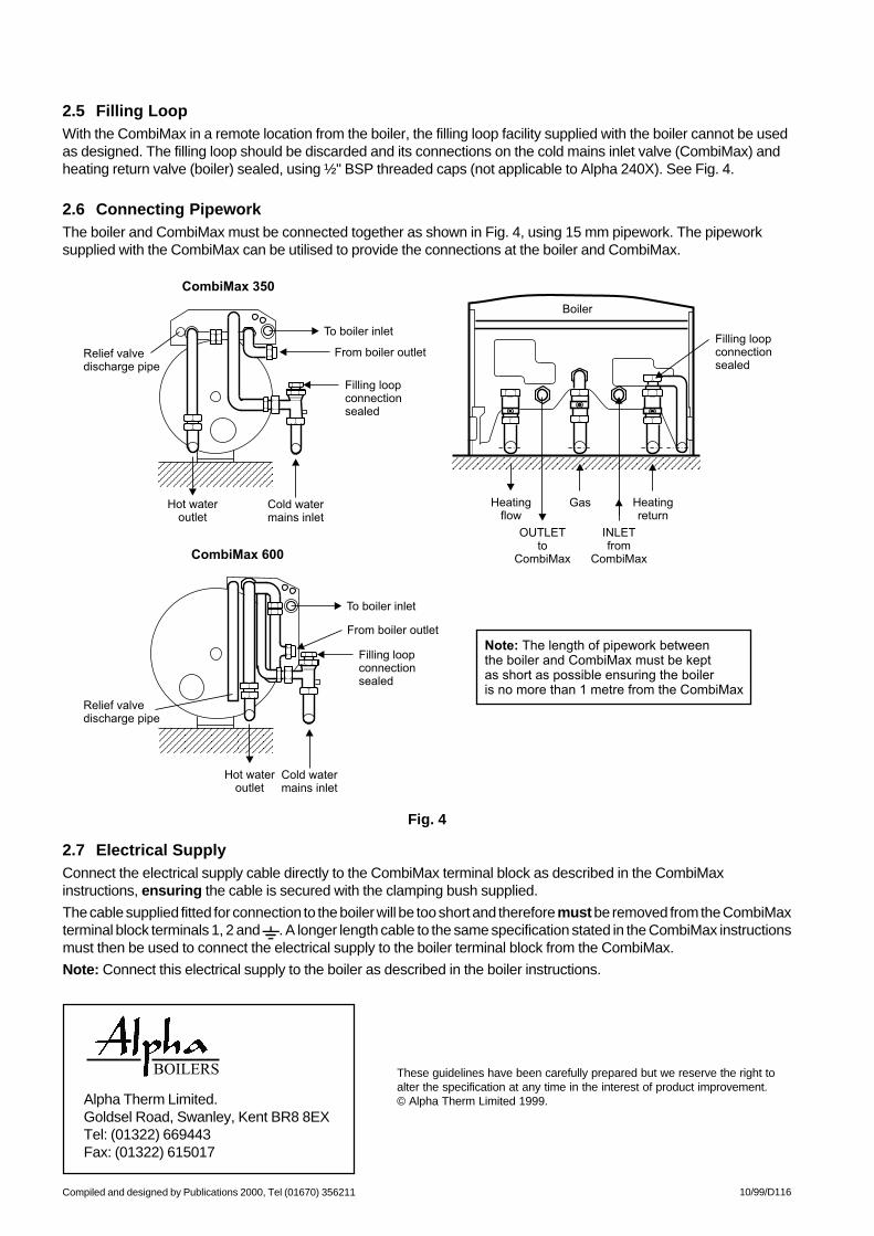
12.8 FILLING LOOPWith the CombiMax in a remote location from the boiler, the filling loop facility supplied with the boiler cannot be used asdesigned. The filling loop should be discarded and its connections on the cold mains inlet valve (CombiMax) and heating returnvalve (boiler) sealed, using ½" BSP threaded caps (not applicable to Alpha 240X). See Fig. 16.
12.9 CONNECTING PIPEWORKThe boiler and CombiMax must be connected together as shown in Fig. 16, using 15 mm pipework. The pipework supplied withthe CombiMax can be utilised to provide the connections at the boiler and CombiMax.
12.10 ELECTRICAL SUPPLYConnect the electrical supply cable directly to the CombiMax terminal block as described in section 4.7, ensuring the cable issecured with the clamping bush supplied.
The cable supplied fitted for connection to the boiler will be too short and therefore must be removed from the CombiMax terminalblock terminals 1, 2 and . A longer length cable to the same specification stated in section 3.1 must then be used to connect theelectrical supply to the boiler terminal block from the CombiMax.
Note: Connect this electrical supply to the boiler as described in the boiler instructions.

Installation and ServicingInstructions
Leave these instructions with the User
Alpha CombiMax2kW Immersion Heater Kit
Suitable for use with theCombiMax 350 and 600 Unvented Hot Water Store
Goldsel Road,Swanley, Kent BR8 8EX
Fax: (01322) 615017
For Technical help or for Service call ...ALPHA HELPLINETel: (01322) 669443
These instructions must be used in conjunction with the Installation instructions providedwith the selected combination boiler and CombiMax.
Immersion heater kit - Part No. 1000462

2 Alpha CombiMax Immersion Heater
The Alpha Immersion Heater is for use with the Alpha CombiMax 350 and 600 unvented secondary hot water storage cylinderand must be obtained from Alpha Therm Ltd. (Immersion heater kit Part No. 1000462). It's purpose is to deliver a limitedamount of hot water when the boiler is not working.
A 3 kW immersion heater MUST NOT be fitted.
The 2 kW heater consists of a 1¼" BSP threaded boss, with control and overheat thermostats. The control thermostat settinghas been factory set to 55°C and must not be adjusted.
Notes:1. It is only possible to fit this immersion heater to a CombiMax produced after February 1999, i.e. after SerialNo. A90600001.
2. A minimum clearance of 350 mm below the CombiMax is required for installation and servicing. A clearanceless than 350 mm will not allow the heater to be replaced.
1 INTRODUCTION
Fig. 1
The Alpha immersion heater requires a 230/240 V ~ 50 Hz mains supply, fused at 10 A.
The immersion heater must be earthed.
The heater must be connected to an independent electrical supply, i.e. the supply used for the CombiMax, boiler and externalcontrols must not be used.
The heater should be connected to a 10 A fused double pole switch with a contact separation of at least 3 mm in both poles ora 10 A fused 3-pin plug and unswitched socket outlet (both complying with BS1363). Ensure heat resisting flexible cable (i.e.85°C) not less than 1.5 mm² complying with BS6141:Table 8 or Table 15, is used for connection to the heater.
All external wiring must be in accordance with the current IEE Wiring Regulations (BS7671).
2 ELECTRICAL SUPPLY
3 INSTALLATION
Where possible the immersion heater should be fitted before installation of the CombiMax. If this has not been possible, thendrain the CombiMax store as described in section 8.2 of the CombiMax instructions.
To fit the heater a minimum clearance of 350 mm is required beneath the CombiMax.
Fit the heater as follows:-
1. Remove the blanking cap from the boss at the bottom of the CombiMax storage cylinder.
2. Ensure all sealing material is removed, and that there is no damage to the sealing face and thread of the boss.
3. Apply a small amount of grease to the 'O' ring seal and engage the heater into the boss and gently tighten using anappropriate spanner.
4. Remove the nut securing the heater cover and remove the cover. Pass the electrical supply cable through the cable clampand connect as follows:-
Brown wire to L, Blue wire to N and Green/Yellow wire to .
Ensure correct polarity and that the cable is secured in the cable clamp as shown. See Fig. 1.
Note: Ensure that the length of the earth wire is such that if the supply cable is pulled out of the clamp, the live and neutralwires become taut before the earth wire.

3Alpha CombiMax Immersion Heater
5. Check that all screws/terminals have been tightened and replace the cover in reverse order.
Note: Do not adjust the thermostat as it has been factory set.
6. Carry out electrical system checks - short circuit, polarity, earth continuity and resistance to earth using a suitable multimeter.
Warning: DO NOT switch on the electrical supply to the heater until the storage cylinder is full of water.
4 USER INFORMATION
The User must be advised that the immersion heater has been fitted for emergency use only, in the rare situation where theboiler/CombiMax has broken down. It must not be switched on unless the boiler cannot deliver hot water.
If the immersion heater is switched on, a limited supply of hot water will be supplied from the storage cylinder.
If the immersion heater is used when the CombiMax and boiler are operating correctly, it will not deliver extra hot water.
If the immersion heater is used when the boiler has failed, it will take approximately 1 hr for the CombiMax 350 andapproximately 1½ hr for the CombiMax 600 to heat the water in the store. This will provide approximately 30 litres of hot waterfrom the 350 model and approximately 50 litres of hot water from the 600 model.
5 SERVICING/REPLACEMENT OF PARTS
Before servicing or replacement of components is carried out on the boiler and CombiMax, ensure that the independentelectrical supplies to the immersion heater, boiler and CombiMax have all been isolated.
No regular servicing of the immersion heater is required.
A minimum clearance of 350 mm is required below the CombiMax to enable replacement of the heater or thermostat.
5.1 CONTROL/OVERHEAT THERMOSTAT
The immersion heater consists of a control and an overheat thermostat. If the control thermostat fails, the overheat thermostatwill operate at approximately 90°C, i.e. very hot water and stop the heater from working. If this occurs, the thermostat assemblymust be replaced as follows:-
1. Ensure all the electrical supplies to the heater, boiler and CombiMax are isolated.
2. Remove the nut securing the heater cover and remove the cover.
3. Disconnect the electrical connections and carefully lever out the thermostat from the housing.
4. Fit a new thermostat and re-assemble in reverse order.
5.2 IMMERSION HEATER
1. Drain the CombiMax as described in section 8.2 in the CombiMax instructions.
2. Remove the old heater and fit a new one as described in section 3 of these instructions.

Manual compiled and designed by Publications 2000, Tel (01670) 356525
Alpha Therm Limited.Goldsel Road, Swanley, Kent BR8 8EXTel: (01322) 669443Fax: (01322) 615017
Part No. 0001122/2
These instructions have been carefully prepared but we reserve the right toalter the specification at any time in the interest of product improvement.© Alpha Therm Limited 1999.
09/99/D118

Installation Guidelines
To fit theAlpha CombiMax 350 and 600
in a remote location from the boiler
Goldsel Road,Swanley, Kent BR8 8EX
Fax: (01322) 615017
For Technical help or for Service call ...ALPHA HELPLINETel: (01322) 669443
These guidelines must be used in conjunction with the Installation instructions providedwith the selected combination boiler and CombiMax.
Only a CombiMax produced after February 1999 can be installed remote from the boiler.

2 Alpha CombiMax Remote Location
The Alpha CombiMax has been designed to fit onto the left hand sideof an Alpha 240/280 boiler. However, it is now possible (using aCombiMax 350 or 600 produced after February 1999, i.e. from SerialNo. A906) to install it up to a distance of 1 metre from the boiler in thepositions shown in Fig. 1.
The pipework between the boiler and CombiMax must be kept asshort as possible and be no more than 1 metres in length, with thenumber of bends kept to a minimum.
Notes: 1. A CombiMax produced before February 1999, i.e. beforeSerial No. A906 must not be fitted remote from the boiler.
2. A CombiMax fitted remote has no casing.
1 INTRODUCTION
Fig. 1
Possible locationsfor the CombiMaxin relation to theboiler.
Fig. 2
1.1 CombiMax Schematic - remote location from boiler
1. Gas service cock2. On/Off valve and filter3. On/Off valve4. On/Off valve and filter5. DHW pump6. Pressure reducing valve with filter and check valve7. Drain point8. DHW expansion relief valve9. Store thermostat
10. DHW expansion vessel11. Manual air vent12. DHW temperature/pressure relief valve13. DHW outlet thermostat14. Storage cylinder15. Boiler flow control regulator16. Non return valve17. Immersion heater boss

3Alpha CombiMax Remote Location
2 INSTALLATION INFORMATION
If the CombiMax is to be fitted in a remote location from the boiler, it should be installed as described in theinstructions supplied with the CombiMax together with the following important points:-
2.1 Minimum Clearances Required
2.2 Wall MountingThe wall mounting frame and security strap supplied, are to be used to secure the CombiMax storage cylinder to the wall.
2.3 CasingThe casing components supplied with the CombiMax cannot be used when it is fitted in a remote location from the boiler.
2.4 DHW Expansion VesselFit the expansion vessel near the top of the storage cylinder using the flexible hose supplied. See Fig. 3.
Fig. 3
Compiled and designed by Publications 2000, Tel (01670) 356211
Alpha Therm Limited.Goldsel Road, Swanley, Kent BR8 8EXTel: (01322) 669443Fax: (01322) 615017
These guidelines have been carefully prepared but we reserve the right toalter the specification at any time in the interest of product improvement.© Alpha Therm Limited 1999.
10/99/D116
Fig. 4
2.5 Filling LoopWith the CombiMax in a remote location from the boiler, the filling loop facility supplied with the boiler cannot be usedas designed. The filling loop should be discarded and its connections on the cold mains inlet valve (CombiMax) andheating return valve (boiler) sealed, using ½" BSP threaded caps (not applicable to Alpha 240X). See Fig. 4.
2.6 Connecting PipeworkThe boiler and CombiMax must be connected together as shown in Fig. 4, using 15 mm pipework. The pipeworksupplied with the CombiMax can be utilised to provide the connections at the boiler and CombiMax.
2.7 Electrical SupplyConnect the electrical supply cable directly to the CombiMax terminal block as described in the CombiMaxinstructions, ensuring the cable is secured with the clamping bush supplied.
The cable supplied fitted for connection to the boiler will be too short and therefore must be removed from the CombiMaxterminal block terminals 1, 2 and . A longer length cable to the same specification stated in the CombiMax instructionsmust then be used to connect the electrical supply to the boiler terminal block from the CombiMax.
Note: Connect this electrical supply to the boiler as described in the boiler instructions.

Installation and ServicingInstructions
Leave these instructions with the User
Alpha CombiMaxSecondary Circulation Kit
Suitable for use with theCombiMax 350 and 600 Unvented Hot Water Store
Goldsel Road,Swanley, Kent BR8 8EX
Fax: (01322) 615017
For Technical help or for Service call ...ALPHA HELPLINETel: (01322) 669443
These instructions must be used in conjunction with the Installation instructions providedwith the selected combination boiler and CombiMax.
CombiMax 350 - Secondary circulation kit - Part No. 1000461
CombiMax 600 - Secondary circulation kit - Part No. 1000466

2 Alpha CombiMax Secondary Circulation
CONTENTS
1 Introduction ............................. Page 2
2 Schematic ......................................... 3
3 Installation information ....................... 4
4 Installation ......................................... 4
A CombiMax 350 or 600 can be converted to enable a secondary circulation loop to be directly connected to it, thereby allowingthe supply of domestic hot water immediately a hot water tap is opened. An additional pump is not required to circulate the hotwater within the loop, as the CombiMax pump is used for this function.
Conversion of the CombiMax to enable the secondary circulation must only be carried out using the following kits:-
CombiMax 350 - Secondary circulation kit - Part No. 1000461
CombiMax 600 - Secondary circulation kit - Part No. 1000466
Note: It is only possible to fit the secondary circulation kit to a CombiMax produced after February 1999, i.e. afterSerial No. A90600001.
The kits include all pipework and components, i.e. thermostat, non-return valve and flow regulator, necessary to enable asecondary circulation loop to be connected directly to the CombiMax as shown in Fig. 1.
1 INTRODUCTION
Fig. 1
5 Commissioning ....................... Page 6
6 Operation .......................................... 7
7 Component replacement ................... 7
8 Short parts list ................................... 8

3Alpha CombiMax Secondary Circulation
2 SCHEMATIC
COMBIMAX SCHEMATIC - SECONDARY CIRCULATION
1. Gas service cock
2. On/Off valve and filter
3. On/Off valve
4. On/Off valve and filter
5. DHW pump
6. Pressure reducing valve with filter and check valve
7. Drain point
8. DHW expansion relief valve
9. Store thermostat
10. DHW expansion vessel
11. Manual air vent
12. DHW temperature/pressure relief valve
13. DHW outlet thermostat
14. Storage cylinder
15. Boiler flow control regulator
16. Non return valve
17. Recirculation thermostat
18. Restrictor
19. Immersion heater boss

4 Alpha CombiMax Secondary Circulation
3.1 PIPEWORK INSULATION
As hot water is circulated around the loop from the CombiMax cylinder it loses heat. To minimise heat loss it is essential that allpipework within the circulation loop is adequately insulated. For this reason it is recommended that the secondary loop is in 15 mmpipe, as larger diameter pipework would increase the heat loss.
3.2 ADDITIONAL EXPANSION VESSEL
The expansion vessel supplied with the CombiMax is sized to suit the CombiMax cylinder and a limited length of pipework only.Depending on the length of pipework within the secondary loop an additional expansion vessel may be required. If there is insufficientexpansion vessel capacity the expansion relief valve fitted to the cylinder of the CombiMax will operate and discharge.
As a guideline, If the secondary loop is less than 25 metres of 15 mm diameter pipe, an additional expansion vessel should notbe required. If the loop is longer, it is recommended that an additional expansion vessel is fitted in the circuit, where it will beaccessible for inspection and servicing.
Note: The vessel must be acceptable for use on mains water and have a pre-charge of 2.5 bar. A suitable vessel is availablefrom Alpha Therm, Part No. 0001045.
3.3 DHW CLOCK
Sometimes it may be required to switch off the secondary circulation overnight to avoid unnecessary heat loss and operation of theappliance. This can be achieved by connecting an external clock to the 'Ext Prog' terminals on the CombiMax terminal block, asshown in Fig. 4.
3.4 CLEARANCES REQUIRED
These are the same as stated in the installation and Servicing instructions supplied with the CombiMax.
3 INSTALLATION INFORMATION
4.1 UNPACKING
Before installation the CombiMax must be converted for secondary circulation. Carefully unpack the CombiMax box. Check thatyou have all the components and place them safely to one side.
Check that the secondary circulation kit is the correct one, i.e. CombiMax 350, Part No. 1000461 or CombiMax 600, Part No.1000466.
The kit supplied contains the following:-
a. Secondary circulation return pipe, fitted with non-return valve and recirculation thermostat with cable. (Pipe 'A', inschematic diagram on page 3).
b. Recharge pipe. (Pipe 'B', in schematic diagram on page 3).
c. Secondary circulation flow/boiler return pipe assembly, fitted with restrictor, flow regulator and housing. (Pipe 'C', inschematic diagram on page 3).
d. Literature, sealing washers and 'Converted to secondary circulation' label (fitted to the thermostat cable).
4 INSTALLATION
Fig. 2a - CombiMax 350 Fig. 2b - CombiMax 600

5Alpha CombiMax Secondary Circulation
4.2 CONVERT THE COMBIMAX FOR SECONDARY CIRCULATION
The CombiMax must be converted before mounting it on the wall as described below.
1. Place the storage cylinder on its back, then remove and discard the pipework shown in Fig. 2a or 2b.
2. Fit the pipework 'A' and 'B' (section 4.1), supplied in the kit to the storage cylinder in place of the pipework removed, see Fig2a or 2b. Ensure that all joints have been fitted with the sealing washers supplied.Note: Pipework 'C' (section 4.1) is used to connect between the boiler outlet and the end of pipe 'B', see Figs. 2a and 3a forCombiMax 350 and 2b and 3b for CombiMax 600.
3. Connect the cable from the re-circulation thermostat to the CombiMax terminal block by removing the screws securing theterminal box cover and connecting the wires to terminals 7 and 8. See Fig. 4.Ensure the leads are passed through the grommetted hole in the fittings plate and secured in the terminal box with theclamping bush supplied.Replace the terminal box cover.
4.3 FIT THE COMBIMAX
Mount the CombiMax on the wall as described in sections 4.1 to 4.5 (inclusive) of the Installation instructions supplied with theCombimax.
4.4 CONNECT THE PIPEWORK - Fig. 3a or 3b
1. Thoroughly flush out all the water pipework.Note: Ensure that all the plastic caps have been removed from the boiler connections.
2. Secure all the valves/fittings between the CombiMax and boiler as shown in Fig. 3a (CombiMax 350) or 3b (CombiMax600). Use the washers supplied and ensure the necessary fittings face the rear wall. Fit the union bends to the valves.Notes: a. If soldering to the boiler union bends, ensure the bends are not connected to the valves, otherwise the internal
seals may be damaged.b. Ensure the 22 mm isolating valve with the filter is fitted to the heating return connection as shown in Fig. 3a or 3b.c. Fit the pressure relief valve connection before the isolating valves.
3. Connect the system pipework to the boiler.Note: Do not forget that the heating system pressure relief valve discharge pipe must be routed clear of the boiler to adrain in such a manner that it may be seen, but cannot cause injury to persons or property.
4. Connect the discharge pipework from the temperature/pressure relief and expansion relief valves to the tundish supplied.Note: This pipework must be installed as recommended in Unvented Hot Water Storage System, section 3.4 of theCombiMax Installation instructions.
Note: Disconnect the filling loop after fillingthe central heating system.
A - Heating flow (22 mm)B - Secondary circulation loop (15 mm)C - Gas inlet (22 mm)D - Cold water mains inlet (15 mm)E - Heating return (22 mm)F - Heating pressure relief valve (15 mm)G - Temperature/pressure expansion relief
discharge pipeH - Drain point for DHW storage
Note: Both Heating return and Cold watermains inlet valves contain serviceable filters.
Fig. 3a - CombiMax 350

6 Alpha CombiMax Secondary Circulation
4.5 CONNECT THE MAINS SUPPLY - Fig. 4
Connect the electrical mains supply to the CombiMax and boiler as described in the CombiMax Installation instructions. Alsorefer to Fig. 4.
Ensure that all cables are secured with the clamping bushes supplied.
5 COMMISSIONING
Commission the boiler and CombiMax as described in the instructions supplied with both appliances.
Ensure that all the air has been cleared from the domestic hot water pipework by opening all the hot water taps after theCombiMax store has been fully recharged to its maximum temperature.
The time to reheat the complete system, i.e. the CombiMax store plus the secondary circulation loop, will depend on the lengthof the secondary circulation loop.
Fig. 3b - CombiMax 600
Note: Disconnect the filling loop after fillingthe central heating system.
A - Heating flow (22 mm)B - Secondary circulation loop (15 mm)C - Gas inlet (22 mm)D - Cold water mains inlet (15 mm)E - Heating return (22 mm)F - Heating pressure relief valve (15 mm)G - Temperature/pressure expansion relief
discharge pipeH - Drain point for DHW storage
Note: Both Heating return and Cold watermains inlet valves contain serviceable filters.
Fig. 4 - CombiMax terminal block

7Alpha CombiMax Secondary Circulation
6 OPERATION
When a secondary circulation loop is fitted, the CombiMax will still operate as described in section 6 of the instructions suppliedwith the CombiMax, except that the DHW pump will not be switched off until both the store thermostat and recirculationthermostat are satisfied. The recirculation thermostat senses the temperature of the water returning to the store from thesecondary circulation loop and will only switch the pump off when the water in the loop has reached the set temperature ofapproximately 56°C.
Domestic hot water always takes priority over central heating. If a demand for hot water is required during a central heatingperiod, the boiler will automatically switch to the hot water mode until the demand is satisfied, i.e. storage water and circulationloop have reached the set temperature. This interruption in the central heating is only when the demand for hot water ispresent, or when recharging of the circulation loop and store is required.
It is the law that any service work must be carried out by a competent person.Warning: Before replacing any boiler or CombiMax components, isolate the electrical supply and close the boiler gas service cock.After replacement of any components, check the operation of the CombiMax. Ensure that all the controls are returned to their original settings.Refer to the instructions supplied with the boiler and CombiMax for full details on replacement of all other components.
7.1 ACCESS
1. To gain access to the CombiMax, remove the bottom two screws securing the CombiMax front casing and lift the casingup slightly and remove.
2. To gain access to the boiler, refer to the instructions supplied with the boiler.
7.2 DRAINING THE COMBIMAX - See CombiMax Schematic illustration
Isolate the electricity supply.Remove the front casing as described in section 7.1. Close the mains water inlet valve. Open any hot tap below the level of the storeand open the manual air vent on top of the store. Allow as much water to drain from the store as possible. To drain the remainingwater from the store, open the drain tap at the bottom of the store.Note: Some water will remain in the components and care must be taken when removing them.
7.3 RECIRCULATION THERMOSTAT - See CombiMax Schematic illustration
1. Gain access as described in section 7.1. Ensure the electricity supply is isolated.
2. Cut and remove the plastic cable tie around the plug and disconnect the plug from the thermostat.
3. Remove the two fixing screws and remove the thermostat from the mains water inlet pipe.
4. Fit the new thermostat and re-assemble in reverse order, fitting a new cable tie around the plug and pipework.
7.4 NON RETURN VALVE - See CombiMax Schematic illustration
1. Drain the CombiMax as described in section 7.2.
2. Undo the unions of the pipe containing the non return valve.
3. Remove the non return valve
4. Re-assemble in reverse order with a new valve and seals.
5. Refill the store as described in section 7.6.
7.5 BOILER FLOW CONTROL REGULATOR - See Fig. 3
1. Drain the CombiMax as described in section 7.2.
2. Refer to Fig. 3 and disconnect the pipework containing the regulator.
3. Remove the regulator from its housing.
4. Re-assemble in reverse order with a new regulator.
5. Refill the store as described in section 7.6.
7.6 REFILL THE DOMESTIC HOT WATER SYSTEM
Open the mains water inlet valve and allow the Combimax store and boiler to fill. When filled, open the manual air vent on thetop of the store (refer to schematic diagram on page 3) until all the air has been vented. Turn on all the hot water taps and allowwater to flow until no air is present. Turn off the taps. Cover all electrical components beneath the CombiMax pump and thenrelease the pump bleed screw until all the air has been vented. Retighten the screw.
7 COMPONENT REPLACEMENT

8 SHORT PARTS LIST
Refer to section 2
Item 17Item 16Item 15
Description
Recirculation thermostatNon-return valveBoiler flow control regulator
Qty.
111
Alpha Part No.
0001111K00010480001059
Model
BothBothBoth
SECONDARY CIRCULATION ONLY
Manual compiled and designed by Publications 2000, Tel (01670) 356525
Alpha Therm Limited.Goldsel Road, Swanley, Kent BR8 8EXTel: (01322) 669443Fax: (01322) 615017
Part No. 0001120/2
These instructions have been carefully prepared but we reserve the right toalter the specification at any time in the interest of product improvement.© Alpha Therm Limited 1999.
09/99/D118

ENSURE THE BOILER IS CONVERTED BEFORE FITTING THE COMBIMAXSee Figs. 3, 4, 5 and 6
NOTE: After converting the boiler, fit the label supplied, to the inside of the hinged cover so that it can be seen.
Fig. 3
Fig. 4
Fig. 5 - Differential pressure sensor BEFORE modification
RestrictorFilter
Differentialpressure sensor
Fig. 6 - Differential pressure sensor AFTER modification
3. Remove the differential pressure sensor from the boilerusing the spanner provided as follows:-Disconnect the two flow sensing pipes from the righthand manifold, then unscrew and remove the end fittingcontaining the filter/restrictor as shown in Fig. 4.
4. Modify the differential pressure sensor (see Figs. 5 and 6) as follows:-
a. Unscrew fitting 'A' and discard the components A, B and C as shown in Fig. 5.
b. Screw fitting 'D' (supplied in the conversion kit) into the sensor body as shown in Fig. 6.
5. Re-assemble the differential pressure sensor into the boiler in reverse order.
1. Lower the front cover and loosen the two fixing screwssecuring the control panel as shown in Fig. 3.
2. Remove the left hand side panel of the boiler by removingthe top and two bottom screws as shown in Fig. 3.
The boiler may be converted before or after mounting it onto the wall as described below.
When mounting the boiler onto the wall follow the installation instructions supplied with the boiler.Note: Do not connect the pipework, electrical mains supply or fit the flue until the CombiMax has been fitted.
C B A
D

SPARE PARTS LIST
ForCombiMax 350/600 Unvented Hot Water Store
(from Serial No. A90600001)used with the
Alpha 240/280 range of Combination boilers
August 2002
Page 2
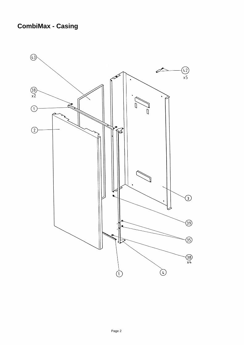
CombiMax - Casing
Page 3
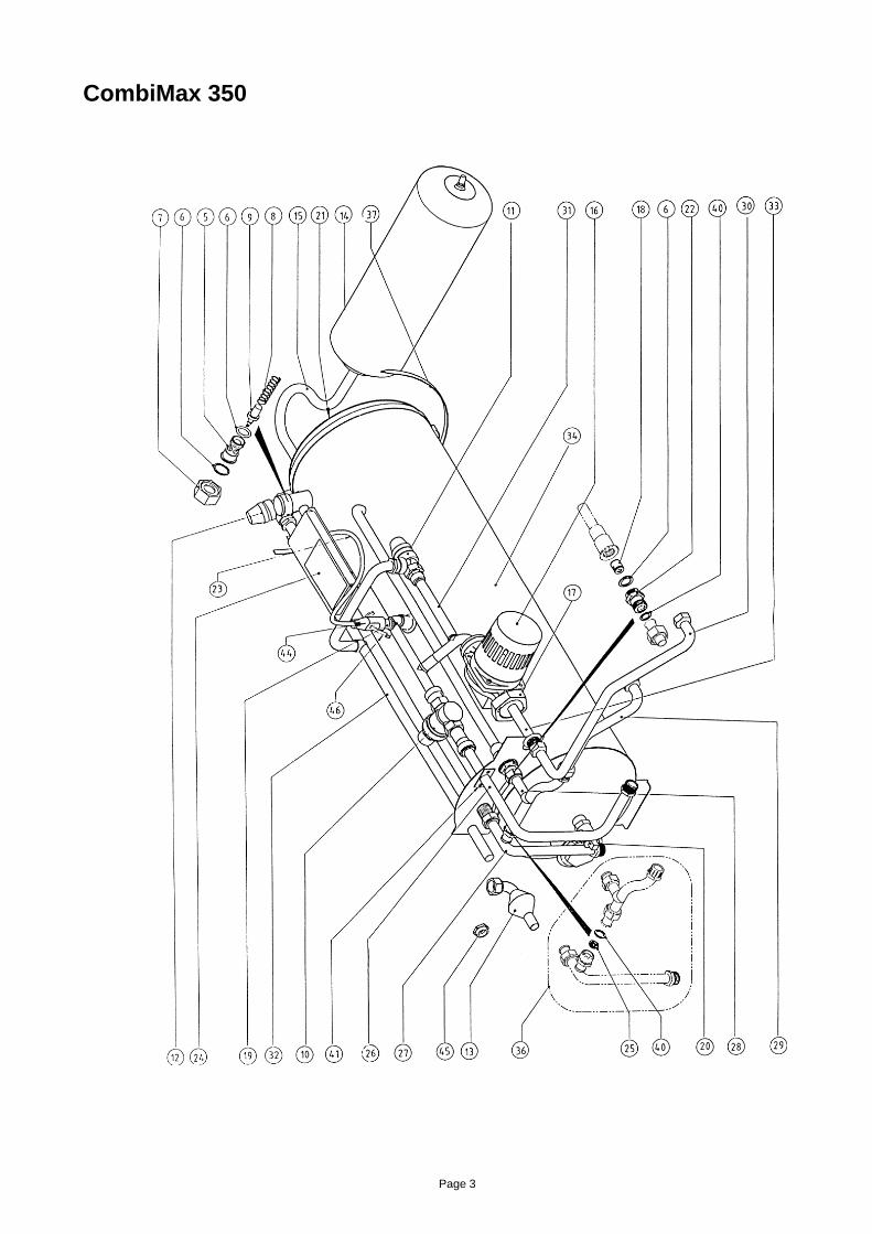
CombiMax 350

Page 4
CombiMax 600

Page 5
CombiMax 350 - Secondary circulation kit
CombiMax 600 - Secondary circulation kit

Page 6
6.0001060
6.0001053
6.0001062
6.0001061
6.0001051
6.0001083
6.0001064
6.0001040
6.0001039
6.0001041
6.0001042
6.0001043
6.0001044
6.0001045
6.0001046
6.0001047
6.0001065
6.0001048
6.0001049
1.018062
6.0001066
6.0001067
6.0001068
6.0001078
6.0001059
6.0001069
6.0001070
6.0001071
6.0001072
6.0001073
6.0001074
6.0001075
6.0001076
6.0001077
6.8240550
6.0001090
6.0001091
6.0001079
6.0001080
6.0001083
6.0001081
6.0001082
6.0001089
6.5626550
6.0001109
6.5210010
6.0001110
6.0001111
6.0001112
6.0001115
6.0001095
6.0001096
6.0001097
6.0001061
6.0001051
6.0001083
6.0001064
6.0001040
6.0001039
6.0001041
6.0001042
6.0001043
6.0001044
6.0001098
6.0001046
6.0001047
6.0001065
6.0001048
6.0001049
1.018062
6.0001066
6.0001067
6.0001068
6.0001078
6.0001059
6.0001099
6.0001100
6.0001101
6.0001102
6.0001103
6.0001104
6.0001105
6.0001106
6.0001107
6.8240550
6.0001092
6.0001091
6.0001079
6.0001080
6.0001083
6.0001081
6.0001082
6.0001089
6.5626550
6.0001109
6.5210010
6.0001110
6.0001111
6.0001112
6.0001114
DescriptionCombiMax600
CombiMax350
RefNo.
Case support - Top/Bottom
Front door with printing
Wall mounting frame
Case support - side
Wax thermostat holder
‘O’ ring seal (part of seal kit)
Nut 22 mm - wax thermostat
S/Steel spring - wax thermostat
Wax element
Pressure reducing valve - 2.5 bar
Expansion relief valve - 4 bar
Temp/Pressure valve - 7 bar
Tundish
Expansion vessel - 5 litre, 2.5 bar
Expansion vessel - 4 litre, 2.5 bar
Flexible hose
Pump - Grundfos bronze
Pump nut
15 mm check valve
Store thermostat - (53°C-15)
Drain valve
Air vent
Check valve housing
Wiring assembly
Electrical box cover
Flow regulator - 8 litre
Inlet pipe
By-pass outlet pipe
By-pass inlet pipe
Boiler return pipe
Boiler flow pipe
Pump pipe assembly
Discharge pipe
Pump outlet pipe
Cylinder assy. no components (foamed)
Captive nut M4
By-pass pipe assy. with 8 lt flow regulator
Cylinder tie (1200 x 9)
Spring fastener (black)
Spring fastener (silver)
Sealing washer pack (part of seal kit)
Screw M4 x 10 mm
Nut M4
Screws, plugs and washers pack
Boiler L/H side panel
Plug for thermostat
Boiler conversion restrictor
Thermostat plug tie (200 x 3.6)
Sec circulation thermostat - (53°C-9)
Sec circulation flow regulator housing
Sec circulation re-charge pipe
1
2
3
4
5
6
7
8
9
10
11
12
13
14
14
15
16
17
18
19
20
21
22
23
24
25
26
27
28
29
30
31
32
33
34
35
36
37
38
39
40
41
41
42
43
44
45
46
47
48
49

Page 7
DescriptionCombiMax600
CombiMax350
RefNo.
50
51
-
-
-
-
-
-
6.0001117
6.0001119
6.0001052
6.0001056/3
6.0001057/2
6.0001084
6.0001120
6.0001085
6.0001116
6.0001118
6.0001052
6.0001056/3
6.0001057/2
6.0001084
6.0001120
6.0001085
Sec circulation return pipe
Sec circulation flow/boiler return pipe
Spanner for boiler conversion
Installation/Servicing manual
User instructions
Boiler conversion instructions
Sec circulation instructions
Label - DHW knob

Alpha Therm Limited.Goldsel Road, Swanley, Kent BR8 8EXTel: (01322) 669443Fax: (01322) 615017

User'sInstructions
Goldsel Road,Swanley, Kent BR8 8EX
Fax: (01322) 615017
For Technical help or for Service call ...ALPHA HELPLINETel: (01322) 669443
Alpha CombiMax 350 and 600Unvented Hot Water Store
for use with theAlpha 240/280 Range of Gas Fired Combination Boilers
Leave these instructions with the User
Building Regulations
Certificate No. ETC 03198
These instructions must be used in conjunction with the Installation instructions providedwith the selected combination boiler.

2
1 DESCRIPTION
2 USER CONTROLS
The CombiMax 350 and 600 are wall mounted unvented hot water storage cylinders for use only with the Alpha 240/280 rangeof gas fired combination boilers.
The CombiMax will provide constant hot water at temperatures of up to 56°C for as long as required.
If applicable, pull the controls panel forward and down to gain access to the controls.
There are no separate user controls provided for the CombiMax and all the boiler controls are used as described in theinstructions supplied with the boiler, with the exception of the domestic hot water thermostat.
The domestic hot water thermostat must always be set to the maximum setting. A label has been supplied which should havebeen positioned over the domestic hot water thermostat knob, as shown below, to ensure the maximum setting is maintained.
Clock(if fitted)
SystemPressureGauge
CentralHeatingThermostat
DomesticHot WaterThermostat( )set at maximum
SelectorSwitch
BurnerViewing Window
0 THERMOSTAT 0 THERMOSTAT 0 SELECTOR
bar0 4
3
2
1
IndicatorNeons
RedResetButton
WhiteResetButton
RESET
RESETIMPORTANT
This hot waterthermostat mustalways be set at
maximum
(i.e. turned fullyclockwise)
Alhpa 240P and Alpha 280P
Alpha 240E and 280E
Clock(if fitted)
SystemPressureGauge
CentralHeatingThermostat
DomesticHot WaterThermostat( )set at maximum
SelectorSwitch
GasControl
IndicatorNeons
Pilot and BurnerViewing Window
0 THERMOSTAT 0 THERMOSTAT 0 SELECTOR GAS
OFF
bar0 4
3
2
1
IMPORTANTThis hot water
thermostat mustalways be set at
maximum
(i.e. turned fullyclockwise)

3
4 HOT WATER USE
5 USING A SHOWER
3 COMBIMAX OPERATION
Refer to the instructions supplied with the boiler for full details of the operation of the boiler.
The CombiMax will supply hot water provided the selector switch on the boiler is set to either or .
Note: The clock on the boiler (if fitted) only controls the operating times of the central heating, not domestic hot water - DHW is availablecontinuously, unless an external clock has been fitted to control the operating times of the domestic hot water.Domestic hot water supply always takes priority over central heating. If a demand for hot water is required during a central heating period,the boiler will automatically switch to the hot water mode until the demand is satisfied, i.e. storage water is to the required temperature. Thisinterruption in the central heating is only when the demand for hot water is present and should not be noticed by the User.When there is a demand for hot water (by opening a hot tap or temperature of the stored hot water is below the thermostatsetting) the store pump starts and the burner lights, heating the mains water by the DHW heat exchanger. When the water inthe store reaches a temperature of approximately 56°C the store thermostat switches the store pump off.
When a hot tap is opened, hot water is supplied from both the store and boiler. When the temperature within the store fallsbelow the outlet thermostat setting, the hot water flow from the store is stopped and hot water is supplied (at a reduced rate)from the boiler only.
Thermostatic or pressure equalising type - When using these types of shower, as the CombiMax maintains a constant flow temperature,the boiler domestic hot water thermostat must be set to maximum, the shower should maintain a relative constant temperature.
Manual bath mixer type - When using this type of shower, care should be taken to establish a setting of the shower control togive an acceptable temperature at the shower before entering. If you get unacceptable temperature variations with this type ofshower, then a thermostatic or pressure equalising type should be used.
The supply of hot water is almost instantaneous at the CombiMax, but the time taken to reach a tap will depend on the length ofthe pipe between the tap and the CombiMax.
The CombiMax will supply hot water at flow rates up to 18 litres/min. providing the stored hot water is up to the temperature setby the thermostat. When the stored hot water is below the thermostat setting the flow of hot water at the tap is reduced toapproximately half the maximum flow rate, but the temperature of the hot water is maintained for as long as is required.
However, the flow rate is dependent on the mains water pressure, and the length and resistance of the pipework to the hot water outlets.
Alpha 240X
6 CLOCK (if fitted)
If a clock is fitted to the boiler control panel, this will allow you to set the time at which the boiler will operate to provide centralheating. It does not affect the supply of domestic hot water from the CombiMax which is always available whatever the settingon the clock. Details on setting the clock for central heating are detailed in the instructions provided for the boiler.
If an external clock is fitted, this may control both the central heating and supply of hot water from the CombiMax or only thesupply of hot water. Your installer should have informed you of this and how to operate the clock.
Note: When the clock used to set the operating times of the CombiMax is in an OFF position the CombiMax will not operate,i.e. hot water will only be supplied from the water left within the storage cyliner. Therefore the OFF periods should be set attimes when hot water will not be required.
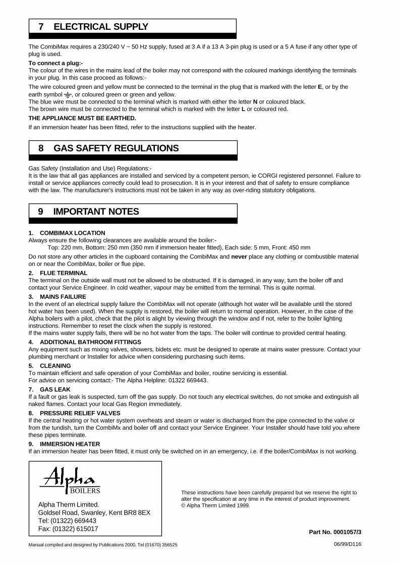
06/99/D116
Part No. 0001057/3
Manual compiled and designed by Publications 2000, Tel (01670) 356525
Alpha Therm Limited.Goldsel Road, Swanley, Kent BR8 8EXTel: (01322) 669443Fax: (01322) 615017
These instructions have been carefully prepared but we reserve the right toalter the specification at any time in the interest of product improvement.© Alpha Therm Limited 1999.
9 IMPORTANT NOTES
1. COMBIMAX LOCATIONAlways ensure the following clearances are available around the boiler:-
Top: 220 mm, Bottom: 250 mm (350 mm if immersion heater fitted), Each side: 5 mm, Front: 450 mm
Do not store any other articles in the cupboard containing the CombiMax and never place any clothing or combustible materialon or near the CombiMax, boiler or flue pipe.
2. FLUE TERMINALThe terminal on the outside wall must not be allowed to be obstructed. If it is damaged, in any way, turn the boiler off andcontact your Service Engineer. In cold weather, vapour may be emitted from the terminal. This is quite normal.
3. MAINS FAILUREIn the event of an electrical supply failure the CombiMax will not operate (although hot water will be available until the storedhot water has been used). When the supply is restored, the boiler will return to normal operation. However, in the case of theAlpha boilers with a pilot, check that the pilot is alight by viewing through the window and if not, refer to the boiler lightinginstructions. Remember to reset the clock when the supply is restored.If the mains water supply fails, there will be no hot water from the taps. The boiler will continue to provided central heating.
4. ADDITIONAL BATHROOM FITTINGSAny equipment such as mixing valves, showers, bidets etc. must be designed to operate at mains water pressure. Contact yourplumbing merchant or Installer for advice when considering purchasing such items.
5. CLEANINGTo maintain efficient and safe operation of your CombiMax and boiler, routine servicing is essential.For advice on servicing contact:- The Alpha Helpline: 01322 669443.
7. GAS LEAKIf a fault or gas leak is suspected, turn off the gas supply. Do not touch any electrical switches, do not smoke and extinguish allnaked flames. Contact your local Gas Region immediately.
8. PRESSURE RELIEF VALVESIf the central heating or hot water system overheats and steam or water is discharged from the pipe connected to the valve orfrom the tundish, turn the CombiMx and boiler off and contact your Service Engineer. Your Installer should have told you wherethese pipes terminate.
9. IMMERSION HEATERIf an immersion heater has been fitted, it must only be switched on in an emergency, i.e. if the boiler/CombiMax is not working.
8 GAS SAFETY REGULATIONS
Gas Safety (Installation and Use) Regulations:-It is the law that all gas appliances are installed and serviced by a competent person, ie CORGI registered personnel. Failure toinstall or service appliances correctly could lead to prosecution. It is in your interest and that of safety to ensure compliancewith the law. The manufacturer's instructions must not be taken in any way as over-riding statutory obligations.
7 ELECTRICAL SUPPLY
The CombiMax requires a 230/240 V ~ 50 Hz supply, fused at 3 A if a 13 A 3-pin plug is used or a 5 A fuse if any other type ofplug is used.
To connect a plug:-The colour of the wires in the mains lead of the boiler may not correspond with the coloured markings identifying the terminalsin your plug. In this case proceed as follows:-
The wire coloured green and yellow must be connected to the terminal in the plug that is marked with the letter E, or by theearth symbol , or coloured green or green and yellow.The blue wire must be connected to the terminal which is marked with either the letter N or coloured black.The brown wire must be connected to the terminal which is marked with the letter L or coloured red.
THE APPLIANCE MUST BE EARTHED.
If an immersion heater has been fitted, refer to the instructions supplied with the heater.