alpha corporation exhibit i subject matter expert report
TRANSCRIPT

Exhibit I
Alpha Corporation Subject Matter Expert Report
ALPHA CORPORATION 1800 Washington Boulevard, Suite 415 Baltimore, MD 21230 410) 646-3044 Fax: (410) 646-3730
March 14, 2014 Montgomery County OIG 51 Monroe Street, Ste 802 Rockville, MD 20850 Attn: Edward L. Blansitt, Inspector General Reference: Analysis of Project Control Dear Mr. Blansitt, As requested and in conformance with our contract, Alpha Corporation has attached our Analysis of Project Controls for the Silver Spring Transit Center. We appreciate the opportunity to assist the County in this matter and if you have any questions or concerns, please contact us. Sincerely, ALPHA CORPORATION Michael Damron, P.E. LEED AP Vice President Enclosure: Analysis of Project Controls
ANALYSIS OF PROJECT CONTROLS
Montgomery County, Maryland Office of the Inspector General Rockville, Maryland
Prepared for:
Prepared by:
March 14, 2014
Alpha Corporation Table of Contents
March 14, 2014 Page 2
ANALYSIS OF PROJECT CONTROLS
MONTGOMERY COUNTY, MD
TABLE OF CONTENTS
I. Terms and Acronyms Used in This Analysis ............................................................................................. 4
II. Executive Summary ....................................................................................................................................... 7
III. Introduction and Purpose ........................................................................................................................... 11
IV. SSTC Background and Project Controls .................................................................................................... 13
Design Project Controls ....................................................................................................................................... 17
Construction Project Controls ............................................................................................................................. 18
Designer Controls ................................................................................................................................................ 18
Montgomery County Personnel .......................................................................................................................... 18
Construction Manager ........................................................................................................................................ 19
Contractor Quality Control Plan ........................................................................................................................ 19
Shop Drawing & Submittal Review .................................................................................................................... 20
Meetings and Conferences ................................................................................................................................... 21
Testing ................................................................................................................................................................. 22
Inspections ........................................................................................................................................................... 23
Considerations ...................................................................................................................................................... 24
V. Pour Strips ..................................................................................................................................................... 27
RFIs and Meetings .................................................................................................................................................. 30
Submittal Review .................................................................................................................................................... 30
Pre‐Installation Conference ..................................................................................................................................... 32
Daily Reports ........................................................................................................................................................... 32
VI. Concrete Composition ................................................................................................................................. 34
Pumped Concrete Samples ...................................................................................................................................... 34
Inspection of Batch Plants ....................................................................................................................................... 35
Concrete Mix Design .............................................................................................................................................. 36
Water to Cement Ratio ............................................................................................................................................ 36
Slump Measurements .............................................................................................................................................. 39
Unhydrated Cement ................................................................................................................................................ 39
Entrapped Air .......................................................................................................................................................... 41
Alpha Corporation Table of Contents
March 14, 2014 Page 3
Entrained Air .......................................................................................................................................................... 42
VII. Concrete Placement ...................................................................................................................................... 42
Post‐Tensioned Tendon Placement .......................................................................................................................... 43
Mild Steel Reinforcing Placement ........................................................................................................................... 44
Thickness of Concrete Floors ................................................................................................................................... 44
VIII. Post Tensioning ............................................................................................................................................ 45
IX. Conclusions ................................................................................................................................................... 52
X. Qualifications ................................................................................................................................................ 54
XI. Appendices ................................................................................................................................................... 55
Appendix A – Contractor Quality Control Plan ............................................................................................... 56
Appendix B – Duties and Functions of DGS Project Management Team ..................................................... 68
Appendix C – Plans of SSTC Floors ................................................................................................................... 73
Appendix D – Cited Standards ........................................................................................................................... 78
Appendix E – Sample Reports ............................................................................................................................ 79
Alpha Corporation Table of Contents
March 14, 2014 Page 4
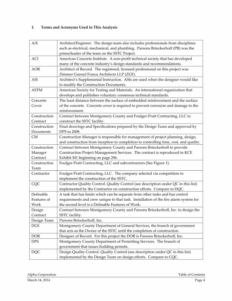
I. Terms and Acronyms Used in This Analysis
A/E
Architect/Engineer. The design team also includes professionals from disciplines
such as electrical, mechanical, and plumbing. Parsons Brinckerhoff (PB) was the
prime/leader of the team on the SSTC Project.
ACI American Concrete Institute. A non‐profit technical society that has developed
many of the concrete industry’s design standards and recommendations.
AOR Architect of Record. The registered, licensed professional on this project was
Zimmer Gunsul Frasca Architects LLP (ZGF).
ASI Architect’s Supplemental Instruction. ASIs are used when the designer would like
to modify the Construction Documents.
ASTM American Society for Testing and Materials. An international organization that
develops and publishes voluntary consensus technical standards.
Concrete
Cover
The least distance between the surface of embedded reinforcement and the surface
of the concrete. Concrete cover is required to prevent corrosion and damage to the
reinforcement.
Construction
Contract
Contract between Montgomery County and Foulger‐Pratt Contracting, LLC to
construct the SSTC facility.
Construction
Documents
Final drawings and Specifications prepared by the Design Team and approved by
DPS in 2008.
CM Construction Manager is responsible for management of project planning, design,
and construction from inception to completion to controlling time, cost, and quality.
Construction
Manager
Contract
Contract between Montgomery County and Parsons Brinckerhoff to provide
Construction Project Management Services. The contract is reproduced in KCE
Exhibit M1 beginning on page 296.
Construction
Team
Foulger‐Pratt Contracting, LLC and subcontractors (See Figure 1).
Contractor Foulger‐Pratt Contracting, LLC. The company selected via competition to
implement the construction of the SSTC.
CQC Contractor Quality Control. Quality Control (see description under QC in this list)
implemented by the Contractor on construction efforts. Compare to DQC.
Definable
Features of
Work
A task that has limits which can be separate from other tasks and has control
requirements and crew unique to that task. Installation of the fire alarm system for
the second level is a Definable Features of Work.
Design
Contract
Contract between Montgomery County and Parsons Brinckerhoff, Inc. to design the
SSTC facility.
Design Team Parsons Brinckerhoff, Inc.
DGS Montgomery County Department of General Services, the branch of government
that acts as the Owner of the SSTC until the completion of construction.
DOR Designer of Record. For this project the DOR is Parsons Brinckerhoff, Inc.
DPS Montgomery County Department of Permitting Services. The branch of
government that issues building permits.
DQC Design Quality Control. Quality Control (see description under QC in this list)
implemented by the Design Team on design efforts. Compare to CQC.
Alpha Corporation Table of Contents
March 14, 2014 Page 5
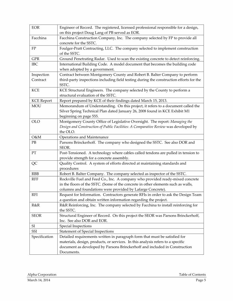
EOR Engineer of Record. The registered, licensed professional responsible for a design,
on this project Doug Lang of PB served as EOR.
Facchina Facchina Construction Company, Inc. The company selected by FP to provide all
concrete for the SSTC.
FP Foulger‐Pratt Contracting, LLC. The company selected to implement construction
of the SSTC.
GPR Ground Penetrating Radar. Used to scan the existing concrete to detect reinforcing.
IBC International Building Code. A model document that becomes the building code
when adopted by a government.
Inspection
Contract
Contract between Montgomery County and Robert B. Balter Company to perform
third‐party inspections including field testing during the construction efforts for the
SSTC.
KCE KCE Structural Engineers. The company selected by the County to perform a
structural evaluation of the SSTC.
KCE Report Report prepared by KCE of their findings dated March 15, 2013.
MOU Memorandum of Understanding. On this project, it refers to a document called the
Silver Spring Technical Plan dated January 26, 2008 found in KCE Exhibit M1
beginning on page 555.
OLO Montgomery County Office of Legislative Oversight. The report: Managing the
Design and Construction of Public Facilities: A Comparative Review was developed by
the OLO.
O&M Operations and Maintenance
PB Parsons Brinckerhoff. The company who designed the SSTC. See also DOR and
SEOR.
PT Post‐Tensioned. A technology where cables called tendons are pulled in tension to
provide strength for a concrete assembly.
QC Quality Control. A system of efforts directed at maintaining standards and
procedures
RBB Robert B. Balter Company. The company selected as inspector of the SSTC.
RFF Rockville Fuel and Feed Co., Inc. A company who provided ready‐mixed concrete
in the floors of the SSTC. (Some of the concrete in other elements such as walls,
columns and foundations were provided by Lafarge Concrete).
RFI Request for Information. Contractors generate RFIs in order to ask the Design Team
a question and obtain written information regarding the project.
R&R R&R Reinforcing, Inc. The company selected by Facchina to install reinforcing for
the SSTC.
SEOR Structural Engineer of Record. On this project the SEOR was Parsons Brinckerhoff,
Inc. See also DOR and EOR.
SI Special Inspections
SSI Statement of Special Inspections
Specification Detailed requirements written in paragraph form that must be satisfied for
materials, design, products, or services. In this analysis refers to a specific
document as developed by Parsons Brinckerhoff and included in Construction
Documents.
Alpha Corporation Table of Contents
March 14, 2014 Page 6
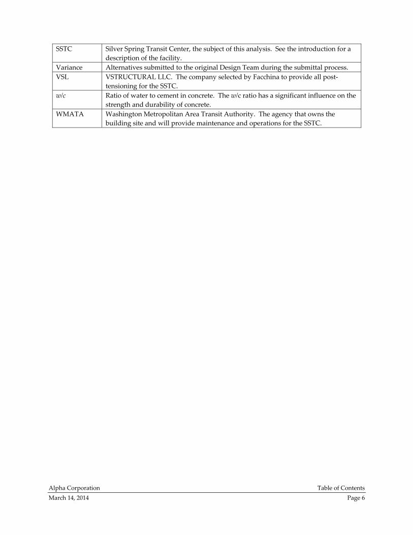
SSTC Silver Spring Transit Center, the subject of this analysis. See the introduction for a
description of the facility.
Variance Alternatives submitted to the original Design Team during the submittal process.
VSL VSTRUCTURAL LLC. The company selected by Facchina to provide all post‐
tensioning for the SSTC.
w/c Ratio of water to cement in concrete. The w/c ratio has a significant influence on the
strength and durability of concrete.
WMATA Washington Metropolitan Area Transit Authority. The agency that owns the
building site and will provide maintenance and operations for the SSTC.
Alpha Corporation Executive Summary
March 14, 2014 Page 7
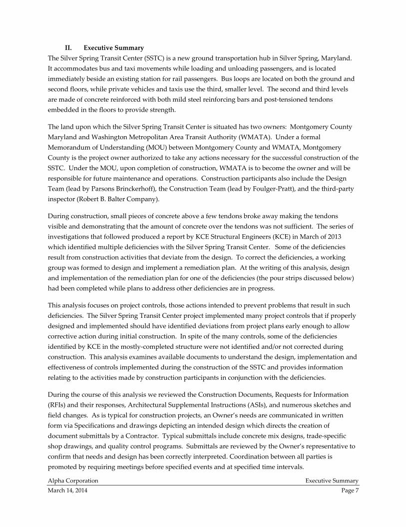
II. Executive Summary
The Silver Spring Transit Center (SSTC) is a new ground transportation hub in Silver Spring, Maryland.
It accommodates bus and taxi movements while loading and unloading passengers, and is located
immediately beside an existing station for rail passengers. Bus loops are located on both the ground and
second floors, while private vehicles and taxis use the third, smaller level. The second and third levels
are made of concrete reinforced with both mild steel reinforcing bars and post‐tensioned tendons
embedded in the floors to provide strength.
The land upon which the Silver Spring Transit Center is situated has two owners: Montgomery County
Maryland and Washington Metropolitan Area Transit Authority (WMATA). Under a formal
Memorandum of Understanding (MOU) between Montgomery County and WMATA, Montgomery
County is the project owner authorized to take any actions necessary for the successful construction of the
SSTC. Under the MOU, upon completion of construction, WMATA is to become the owner and will be
responsible for future maintenance and operations. Construction participants also include the Design
Team (lead by Parsons Brinckerhoff), the Construction Team (lead by Foulger‐Pratt), and the third‐party
inspector (Robert B. Balter Company).
During construction, small pieces of concrete above a few tendons broke away making the tendons
visible and demonstrating that the amount of concrete over the tendons was not sufficient. The series of
investigations that followed produced a report by KCE Structural Engineers (KCE) in March of 2013
which identified multiple deficiencies with the Silver Spring Transit Center. Some of the deficiencies
result from construction activities that deviate from the design. To correct the deficiencies, a working
group was formed to design and implement a remediation plan. At the writing of this analysis, design
and implementation of the remediation plan for one of the deficiencies (the pour strips discussed below)
had been completed while plans to address other deficiencies are in progress.
This analysis focuses on project controls, those actions intended to prevent problems that result in such
deficiencies. The Silver Spring Transit Center project implemented many project controls that if properly
designed and implemented should have identified deviations from project plans early enough to allow
corrective action during initial construction. In spite of the many controls, some of the deficiencies
identified by KCE in the mostly‐completed structure were not identified and/or not corrected during
construction. This analysis examines available documents to understand the design, implementation and
effectiveness of controls implemented during the construction of the SSTC and provides information
relating to the activities made by construction participants in conjunction with the deficiencies.
During the course of this analysis we reviewed the Construction Documents, Requests for Information
(RFIs) and their responses, Architectural Supplemental Instructions (ASIs), and numerous sketches and
field changes. As is typical for construction projects, an Owner’s needs are communicated in written
form via Specifications and drawings depicting an intended design which directs the creation of
document submittals by a Contractor. Typical submittals include concrete mix designs, trade‐specific
shop drawings, and quality control programs. Submittals are reviewed by the Owner’s representative to
confirm that needs and design has been correctly interpreted. Coordination between all parties is
promoted by requiring meetings before specified events and at specified time intervals.
Alpha Corporation Executive Summary
March 14, 2014 Page 8
The three construction deficiencies discussed within this analysis are: the pour strips (narrow sections of
concrete floor cast later than adjacent portions of the floors) in which some of the required reinforcing
was omitted; the concrete composition, which has lower compressive strength than is required by the
Construction Documents; and, concrete placement issues that resulted in slabs of insufficient thickness
and with insufficient concrete cover over reinforcing steel and post‐tensioned tendons. Controls on post‐
tensioning were also analyzed. This analysis mentions deficiencies in design cited in the KCE report,
such as design stresses related to post‐tensioning, but does not specifically examine the design
deficiencies cited in the KCE report or the controls intended to identify and correct design deficiencies.
Pour Strips
The SSTC structure includes three pour strips, one on the top level and two on the second level. Both
pour strips at the second floor are 10’ by 80’ rectangles which were purposely installed at least 60 days
later than the rest of the floor. KCE found that concrete in one of the second level pour strips has less
reinforcing steel than is required by Construction Documents, and neither of the second level pour strips
have post‐tensioned tendons. This structural deficiency resulted from failure of the reviewers to detect
the absence of specified reinforcing steel in shop drawings for one of the pour strips, and failure to
question the absence of any drawings for the two pour strips in the post‐tensioning shop drawing set.
Construction drawings appear to require post‐tensioned tendons in all the pour strips. The absence of
post‐tensioned tendons in the pour strips is consistent with the absence of post‐tensioning shop drawings
for the pour strips. The mild steel reinforcing that was detected by KCE coincides with the reinforcing
shop drawings. Both sets of shop drawings were created by the Construction Team and reviewed by the
Design Team. As a control measure, the manager of the construction quality control plan was required to
review each submittal, including shop drawings, and note any variances from the construction drawings,
but no differences were noted. Further, the RFI process existed to address any apparent inconsistencies or
ambiguities, but that process was not used regarding the pour strips. These controls, as designed, should
have been effective, but implementation of these controls failed in regards to the construction of the pour
strips.
The shop drawings are among the items that were discussed in a pre‐installation conference for post‐
tensioning. At the time this meeting was held, not all post‐tensioned shop drawings were available
because on this project the shop drawings were submitted in phases. Having these shop drawings
available during the pre‐installation conference might have facilitated the work of the reviewers in
identifying the differences between the construction drawings and the shop drawings. Phased
submissions are not prohibited, but steps were not taken to enable reviewers to clearly understand and
track which submittals were outstanding or when delivery of submittals should have been expected.
Concrete Composition
Concrete strength measured by KCE in cores taken from the mostly‐completed structure was in many
cases considerably less than that of test cylinders collected during construction activities. Concrete
properties can be affected by many variables, so many controls were evaluated. Some were found to
Alpha Corporation Executive Summary
March 14, 2014 Page 9
have functioned largely as intended, such as selection of the concrete’s components and vibration of the
fresh concrete to remove entrapped air. Other controls suffered from poor implementation, such as not
inspecting two of the batch plants or failing to correct a trend of low quantities of entrained air. Slump
limits and curing practices met typical industry practice but not the higher standard requested by
WMATA. Confusion about where to take samples and about cold weather limits existed that could have
been avoided by clearer language in the Specifications. Although the proper records were kept and
submitted regarding the amount of water in the concrete mix, KCE testing indicates that in many cases
water was added without permission or documentation.
Concrete Placement
The Design Team, Contractor, and Owner moved quickly to resolve the problem of surfacing post‐
tensioned tendons upon its discovery during construction, so controls on tendon location as implemented
at the end of the project are considered to have been effective. However, the issue of slab thickness
continued until the project’s end even though it was identified about halfway through construction of the
floors. Minutes from a meeting which included all parties in November of 2010 note that, “Area around
popped tendons was surveyed for slab thickness. Slab came in thin in some areas.” Thickness maps of
the entire slab surface at both floors that were later created by KCE show how widespread the problem
was, even in work completed after the aforementioned meeting. Since controls are supposed to allow
corrective action on identified deviations from project plans, the controls on slab thickness were not
effective.
Construction records do not document direct measurements of the thickness of the concrete floor slabs.
The top surface was given the desired shape based on measurements taken by survey equipment
operated while concrete was being placed. Thickness was realized as the difference between formwork
position and concrete top surface, and inspectors could not independently check thickness except at the
perimeter. This construction method, selected by the Contractor, depended upon his own implemen‐
tation being correct. No redundant measurements were taken, despite repeated reminders from the
engineer of record. Future construction efforts should either utilize a construction method that allows
direct measurement of floor thickness so that inspectors can help the Contractor by identifying problems
before the concrete is placed, or the inspectors should perform a second, independent survey during
construction.
This analysis reviewed records kept during construction to evaluate the controls associated with the three
slab deficiencies described above. KCE identified other deficiencies, such as reinforcing bar cover in
columns and cracks in beams and girders. Although these deficiencies were not reviewed as part of this
analysis, some of the conclusions and recommendations relating to controls for the slab deficiencies will
apply to the column, beam and girder deficiencies. “Lessons learned” from the experience of the SSTC
construction will improve effectiveness of remedial actions and will benefit both future projects and the
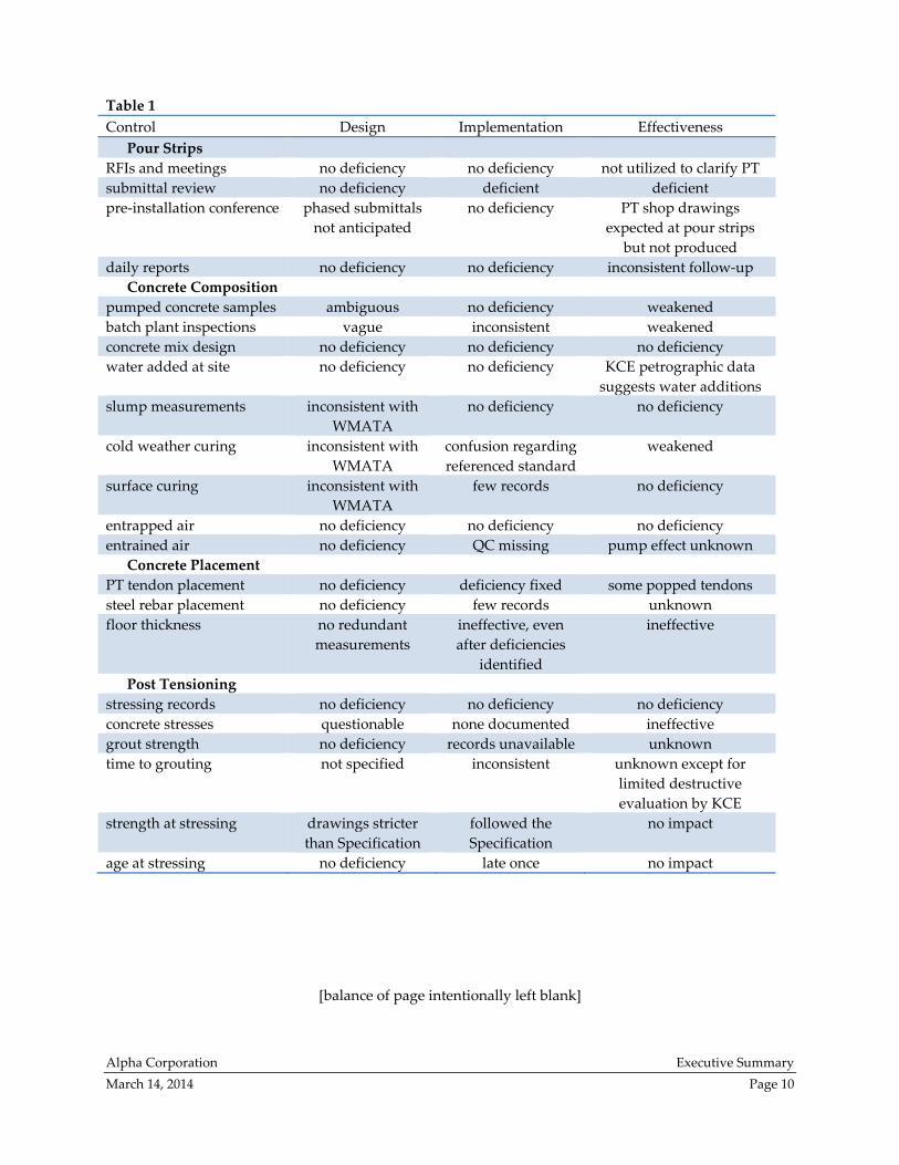
ongoing remediation efforts. Table 1 on page 10 summarizes results of the control analysis with regard to
the control’s design, implementation, and effectiveness.
Alpha Corporation Executive Summary
March 14, 2014 Page 10
Table 1
Control Design Implementation Effectiveness
Pour Strips
RFIs and meetings no deficiency no deficiency not utilized to clarify PT
submittal review no deficiency deficient deficient
pre‐installation conference phased submittals
not anticipated
no deficiency PT shop drawings
expected at pour strips
but not produced
daily reports no deficiency no deficiency inconsistent follow‐up
Concrete Composition
pumped concrete samples ambiguous no deficiency weakened
batch plant inspections vague inconsistent weakened
concrete mix design no deficiency no deficiency no deficiency
water added at site no deficiency no deficiency KCE petrographic data
suggests water additions
slump measurements inconsistent with
WMATA
no deficiency no deficiency
cold weather curing inconsistent with
WMATA
confusion regarding
referenced standard
weakened
surface curing inconsistent with
WMATA
few records no deficiency
entrapped air no deficiency no deficiency no deficiency
entrained air no deficiency QC missing pump effect unknown
Concrete Placement
PT tendon placement no deficiency deficiency fixed some popped tendons
steel rebar placement no deficiency few records unknown
floor thickness no redundant
measurements
ineffective, even
after deficiencies
identified
ineffective
Post Tensioning
stressing records no deficiency no deficiency no deficiency
concrete stresses questionable none documented ineffective
grout strength no deficiency records unavailable unknown
time to grouting not specified inconsistent unknown except for
limited destructive
evaluation by KCE
strength at stressing drawings stricter
than Specification
followed the
Specification
no impact
age at stressing no deficiency late once no impact
[balance of page intentionally left blank]
Alpha Corporation Analysis
March 14, 2014 Page 11
III. Introduction and Purpose
The Silver Spring Transit Center is located in downtown Silver Spring, Maryland, adjacent to the existing
Washington Metropolitan Area Transit Auhorty (WMATA) pasenger rail station. The SSTC’s primary purpose is to serve as a bus terminal, but the SSTC also provides accommodations for passenger
drop‐off and pick‐up for private vehicles and taxis. Under a formal Memorandum of Understanding
(MOU) between the two owners of the land being used for this project, Montgomery County Maryland
and Washington Metropolitan Area Transit Authority (WMATA), Montgomery County is authorized to
manage the development and construction of the SSTC. Upon completion of the project and WMATA’s
acceptance, WMATA will control, operate and maintain the facility.1
A contract to construct the SSTC was signed in 2008. During the construction efforts in October 2010,
tendons became visible in a completed floor when small pieces of concrete above a few tendons broke
away. Concerns about the visible tendons coupled with visible evidence of extensive cracking of concrete
prompted immediate review by the entire construction team, as well as an investigation by both present
and future owners. Montgomery County ultimately retained the services of KCE Structural Engineers,
PC (KCE) to perform a structural evaluation of the SSTC structure and to conduct an extensive document
review. KCE prepared a report of their findings dated March 15, 2013 which is herein referred to as ‘KCE
Report’.
The SSTC is comprised of three floors which are referred to as Levels 305 (sometimes referred to in the
KCE report as Level 300), 330, and 350. Level 305 is constructed at ground level while both Levels 330
and 350 are elevated. The SSTC is primarily constructed from reinforced cast‐in‐place concrete. The
elevated floors are constructed from concrete and reinforced with mild steel and post‐tensioned (PT)
tendons. Post-tensioning is a method of strengthening concrete or other materials with high-strength steel strands or bars, typically referred to as tendons.2 Concrete posts, beams and girders support the
above grade floors. At the East and West ends of the facility on Level 330 there are ten foot wide strips of
slab (pour strips) which encompass the full width of the slab and join the adjacent sections to create a
continuous surface. The concrete in the pour strips was required to be placed a minimum of sixty days
after both adjacent sections of concrete. See Appendix C for drawings showing how the floors were
sequenced by the Contractor.
Objectives, Methodology, and Scope
Management actions intended to prevent problems are called project controls. Management of
construction requires flexibility since each project is different, but construction managers have found
success when they implement systems to control time, cost, scope and quality. Effective controls identify
deviations from project plans early enough to allow corrective action. This project implemented many
controls, but some of the deficiencies identified by KCE in the mostly‐completed structure were not
1 Amended and Restated Memorandum of Understanding between Washington Metropolitan Area Transit Authority and
Montgomery County Maryland dated September 25, 2008, page 9. (KCE Report, Exhibit M1 pdf page 496).
2 “What Is Post‐Tensioning?” Post‐Tensioning Institute, December, 2000.
Alpha Corporation Analysis
March 14, 2014 Page 12
identified and/or not corrected during construction. Therefore, identification of controls that were
omitted, deficient or failed is necessary to avoid repeating mistakes due to misplaced confidence in
deficient controls.
This analysis has three objectives:
to review the construction project controls which were established particular to this project;
to evaluate control implementation with regards to selected deficiencies; and,
to identify any controls that were either omitted or ineffective and the causes of such deficiencies.
The methodology used in this analysis is to evaluate records kept during construction beginning with the
KCE report including its exhibits and attachments. As specific records are found to be lacking in this
primary resource, such records are requested individually. Our knowledge of the construction industry
and of structural design is then applied to interpret records and make appropriate recommendations.
This analysis discusses project controls related to three components for which deficiencies are identified
in the KCE report. The first component in the scope of this analysis was the pour strips. The
investigation performed by KCE identified that the as‐built West pour strip on Level 330 does not have
temperature and shrinkage reinforcing steel required by Construction Documents and that both as‐built
pour strips on Level 330 do not have post‐tensioning tendons. The second component discussed is the
concrete composition. Based on in‐situ testing performed by KCE, the cast‐in‐place concrete in areas of
the structure does not meet compressive strength requirements set in the Construction Documents. The
third component discussed is concrete placement. The KCE report identified that concrete cover over
reinforcing is less than required, and the thickness of the concrete floors does not comply with
Construction Documents. Project controls relating to reinforcing cover and thickness of the concrete in
the floors are similar, thus, the two deficiencies are addressed in one section.
During the course of this analysis we reviewed the Contract Documents, Requests for Information (RFIs)
and their responses, Architectural Supplemental Instructions (ASIs), and numerous sketches and field
changes. However, this analysis does not specifically examine the design deficiencies cited in the KCE
report or controls intended to identify design deficiencies. The design issues noted by KCE include:
a lack of coordination during design between elements, such as electrical and other embedded
items interfering with reinforcing and post‐tensioning, slab geometry and sloping to drains
relative to specified slab thickness;
failure to take into account various required limitations on stress induced during initial post‐
tensioning;
induced forces that overbalanced the structure due to post‐tensioning forces that exceeded the
actual weight of the slabs, beams, and girders, inducing cracks in the structure;
failure to accommodate the stress caused by restraint forces due to the as‐designed integral
concrete walls, columns, and girders, which induced cracking in the slabs and in those elements
themselves;

Alpha Corporation Analysis
March 14, 2014 Page 13
failure to incorporate into the Contract Documents all of the required WMATA Manual of Design
Criteria and the WMATA Standards; and,
under‐design of certain elements of the structure to resist shear forces and torsion forces.
IV. SSTC Background and Project Controls
SSTC Background
Within DGS, the Division of Building Design and Construction is responsible for planning, designing,
and constructing Montgomery County’s public buildings. DGS serves as the Owner during construction
of the Project.3 Preliminary planning for the SSTC began in the 1990’s and required the relocation of the
neighboring WMATA station before plans could be formalized for the SSTC. Under the terms of the
MOU between Montgomery County and WMATA, DGS would lead the construction effort and WMATA
would maintain the structure upon construction completion. The MOU required that WMATA design
standards be incorporated into the design of the SSTC.
Montgomery County entered into contract with Parsons Brinckerhoff, Inc (formerly known as Parsons
Brinkerhoff Quade and Douglas, Inc. and PB Americas, Inc.) in 2004 to design the facility. Herein, this
contract is referred to as “Design Contract.” Parsons Brinckerhoff, Inc (PB) was/is the Designer of Record
(DOR) as well as the Structural Engineer of Record (SEOR) for the project and hired sub‐consultants to
perform design work associated with other disciplines such as architectural design services.4 For the
SSTC project, the term Architect/Engineer (A/E) refers to PB since they hold the prime design contract
with Montgomery County. Per the Montgomery County Contract with PB, the Design Team was
required to prepare progress documents for three phases: Schematic, Design Development, and
Construction Documents. At each phase, PB was required to submit progress drawings, Specifications,
and cost estimates for DGS review, comment, and approval.5
Specifications are detailed requirements written in paragraph form that must be satisfied for materials,
design, products, or services. For example, specifications include explicit material, composition, and
performance requirements for concrete mixes as well as other materials utilized in construction. Specifi‐
cations also provide direction, expectations, and minimum requirements for all parties involved in the
construction process. Specifications are divided into sections with each section focused on one topic or
material.6 Herein, the use of the word “Specification” refers to the specific document developed by PB
and incorporated into the Construction Documents.
3 In the Construction Contract between Montgomery County and Foulger‐Pratt, signatures representing the Owner are those of the
director of DGS and of the chief of the Division of Building Design and Construction. (KCE Report, Exhibit M1 pdf page 17).
4 The Architect of Record, Zimmer Gunsul Frasca Architects LLP (ZGF), performed sub‐consulting architectural services for Parsons
Brinckerhoff, Inc. 5 Design Contract, sections 3.3.1.1 and 6.2. (KCE Report, Exhibit M1 pdf pages 146 and 157). 6 The Specifications are organized into sections that are numbered according to the industry standard called MasterFormat, as set
forth by the Construction Specifications Institute. In this system, the prefix number 01 gives general construction direction such as
submittal procedures or testing requirements while sections with prefix numbers of 02 through 16 provide information for specific
material types.
Alpha Corporation Analysis
March 14, 2014 Page 14
All construction projects must be designed to the minimum requirements dictated in building codes.
Montgomery County has adopted the use of the International Building Code (IBC), which requires
compliance with several other standards prepared by independent committees or industry agencies. For
example, the American Concrete Institute (ACI) develops the standards for concrete and IBC requires all
concrete design to be in conformance with ACI requirements. Another example is the American Society
for Testing and Materials (ASTM) which provides standards for test methods, material performance
requirements, as well as other recommended guides and best practices. The IBC and those standards
referenced by it were utilized by PB in the preparation of the SSTC’s design documents. Since specific
standards are typically revised and updated over time, the standards referenced during the design were
those that were in effect at the time the structure was designed.
The final drawings and Specifications prepared by PB are dated 2008 and are herein called “Construction
Documents.” These were approved by Montgomery County Department of Permitting Services (DPS)
with the issue of a building permit in 2009. DPS enforces standards that control what goes on before,
during and after construction through a mandatory permitting process. The Building Construction
Division of DPS is responsible for ensuring public safety through the enforcement of construction codes
and zoning standards. This is accomplished through engineering plan review and construction
inspection related to the administration and enforcement of building, structural, electrical, mechanical,
fire‐safety, energy conservation, and accessibility codes. DPS is independent from DGS, the county
branch that handled construction of the SSTC.7
Montgomery County contracted with Foulger‐Pratt Contracting, LLC (FP) in 2008 to construct the facility.
Herein, this contract is referred to as “Construction Contract” and FP is referred to as “Contractor.” The
Construction Contract incorporated the Construction Documents developed by PB. As is typical con‐
struction procedure, the Specifications required FP to interpret the Construction Documents and prepare
trade‐specific drawings called shop drawings and to submit product information that communicates FP’s
intended construction methodology and understanding of the proposed construction.
Specifications require the designer of record (PB) to review and approve the shop drawings and
submittals to confirm that FP’s intended construction is in conformance with the design intent. Examples
of required submittals include FP’s intended concrete mix designs as well as their intended quality
control (QC) program.
FP subcontracted all concrete‐related aspects of the project work to Facchina Construction Company, Inc.
(Facchina). Facchina in turn entered into a contract with VSTRUCTURAL LLC (VSL) to provide design,
shop drawings, hardware, and on‐site consultation for post‐tensioned aspects of the concrete work. At
the same time, Gerdau Ameristeel provided shop drawings and materials for the mild steel reinforcing
aspect of the concrete work. R&R Reinforcing, Inc. (R&R) provided installation for Facchina of both the
mild steel reinforcement and the post‐tensioning elements. Lafarge Concrete and Rockville Fuel and
Feed Co., Inc. (RFF) are the companies that supplied ready mix concrete for the SSTC project.
7 Row 11 (Cont’d) of undated, tabulated responses by DGS to WMATA comments on the CQC plan submitted by FP says, “It is
important to realize that the County is not a monolithic organization. The County team managing this project ... [is] DGS, and they
submitted their permit application ... [to] DPS. DGS must satisfy DPS requirements” in order to obtain permission for occupancy.
Alpha Corporation Analysis
March 14, 2014 Page 15
Montgomery County Special Inspections Program
The building code requires certain inspections for all construction projects. Montgomery Countyʹs
Special Inspection Program procedures applicable to the SSTC are those required by Montgomery
County Building Code, and in accordance with the International Building Code (IBC).
Owners of buildings and structures whose elements are subject to special inspections must submit, as
part of the permit application, a Statement of Special Inspections (SSI) prepared by the Structural
Engineer of record (SEOR) as a condition for permit issuance and pre‐construction meeting. This
statement must include a complete list of materials requiring special inspections, the inspections to be
performed and a list of the individuals, approved agencies and firms intended to be retained for
conducting such inspections.
The Special Inspector (SI) is the registered design professional retained by an owner to provide special
inspections and material testing services as specified by appropriate design professionals of record and
approved by the DPS. The SI must provide construction observation and testing services of required
scope and frequency to offer a professional opinion that the constructed project was built in accordance
with the DPS‐approved construction documents, and that construction has been tested and inspected in
accordance with the SSI and applicable codes and standards. The SI may be an agent of, or independent
of the Inspection and Testing agency or the projectʹs SEOR.
The Special Inspector is required to keep records of specified inspections and testing and is required to
furnish specified inspection and test reports to the DPS building official, and to the registered design
professionals of record. All discrepancies are required to be brought to the attention of the contractor for
correction or, if not corrected, to the attention of the code official and to the registered design profession‐
als of record, as appropriate. Interim reports shall be submitted as required by the special inspection
program manual. A Final Report of Special Inspections documenting completion of all required special
inspections and correction of documented discrepancies shall be submitted prior to the issuance of an
occupancy permit.
Montgomery County contracted with Robert B. Balter Company (RBB) to perform all of the third‐party
inspections and field testing under the SSI during the construction efforts.8 Herein, the contract with RBB
is referred to as “Inspection Contract.”
PB was contracted by Montgomery County in 2009 to provide Construction Project Management
Services. Herein, this contract is referred to as “Construction Manager Contract.” The Scope of Services
for PB indicates that they provide a full‐time on‐site project engineer to work under the direction of the
County’s Contract Administrator or his designee, which in this case is DGS.
8 Contract for Inspection and Materials Testing Services between Montgomery County, Maryland and The Robert B. Balter
Company, County Contract No. 6504510207‐AA, signed 10/24/2006. (KCE Report, Exhibit M1 pdf page 333‐405).
Alpha Corporation Analysis
March 14, 2014 Page 16
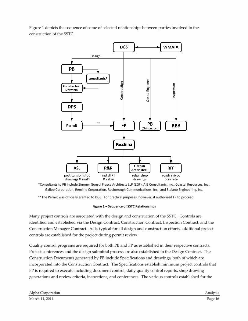
Figure 1 depicts the sequence of some of selected relationships between parties involved in the
construction of the SSTC.
*Consultants to PB include Zimmer Gunsul Frasca Architects LLP (ZGF), A B Consultants, Inc., Coastal Resources, Inc.,
Gallop Corporation, Remline Corporation, Rosborough Communications, Inc., and Staiano Engineering, Inc.
**The Permit was officially granted to DGS. For practical purposes, however, it authorized FP to proceed.
Figure 1 – Sequence of SSTC Relationships
Many project controls are associated with the design and construction of the SSTC. Controls are
identified and established via the Design Contract, Construction Contract, Inspection Contract, and the
Construction Manager Contract. As is typical for all design and construction efforts, additional project
controls are established for the project during permit review.
Quality control programs are required for both PB and FP as established in their respective contracts.
Project conferences and the design submittal process are also established in the Design Contract. The
Construction Documents generated by PB include Specifications and drawings, both of which are
incorporated into the Construction Contract. The Specifications establish minimum project controls that
FP is required to execute including document control, daily quality control reports, shop drawing
generations and review criteria, inspections, and conferences. The various controls established for the

Alpha Corporation Analysis
March 14, 2014 Page 17
SSTC relating to the three deficiencies reviewed in the analysis are described more specifically in the
following paragraphs.
Design Project Controls
The Design Contract included language requiring PB to execute a Design Quality Control (DQC)
program and to initiate early and continuous reviews and coordination with the appropriate government
entities for permits and approvals.9 The Design Contract also required project conferences throughout all
phases of the Project including work sessions as required during the submittal review meetings.10 Phases
included Concept, Schematic, Design Development, and Construction Documents. Exhibit A of the
Design Contract indicates the required scope of services including requirements per discipline for
documents submitted in each phase. Exhibit L of the Design Contract indicates requirements for the
DQC, which are summarized in the next paragraph.
PB was required to submit a DQC plan within 30 calendar days after receipt of a Notice to Proceed. The
Plan was required to include staff names and qualifications for each person assigned a DQC function
including the Design Quality Control Manager who must report directly to a Principal of the firm and
have minimum 10 years of experience in architectural or engineering design with 5 of those years involv‐
ing DQC functions. The plan was also required to include a submittal tracking plan, coordination plan,
design review plan, design schedule, and a cost estimate and analysis form. An orientation meeting was
required and opportunities were provided throughout the Design Contract duration to reconfirm mutual
understanding of the Plan. During the Design Development, Construction Document, and the
Construction Bid phases of design, the DQC Manager must maintain the Plan and submit checklists for
submittal tracking, coordination, design review, and design schedule. During the Construction
Administration Phase, the DQC Manager was required to submit the submittal tracking checklist, a
RFI/Issue tracking checklist, and a review of the Critical Path Method schedule and any related General
Contractor’s claims for delay.11
The copy of the DQC program submitted by PB that was provided to this analysis did not show evidence
of having been maintained after submission. The DQC plan has staff names, but does not provide
qualifications. It includes procedures for tracking documents supplied by third parties, but does not
specifically address submittals. The DQC plan describes coordination and design review without
identifying design elements. Therefore, the DQC program does not meet many of the requirements given
in the Design Contract as explained in the preceding paragraph.
During the course of this analysis we reviewed the Construction Documents, Requests for Information
(RFIs) and their responses, Architectural Supplemental Instructions (ASIs), and numerous sketches and
field changes. However, this analysis does not specifically examine the design deficiencies cited in the
KCE report or controls intended to identify design deficiencies. This analysis reviewed design docu‐
ments only to determine whether specific requirements were presented for Contractor implementation,
9 Contract for Architectural/Engineering Services between Montgomery County, Maryland and Parsons Brinckerhoff Quade &
Douglas, Inc. for Design of Silver Spring Transit Center, County Contract #4504510121‐AA, page 13‐14. (KCE Report, Exhibit M1,
pdf page 141‐142). 10 ibid, page 21. (KCE Report, Exhibit M1, pdf page 149). 11 ibid, pages L‐1 – L‐3
Alpha Corporation Analysis
March 14, 2014 Page 18
because the deficiencies reviewed stemmed from activities which occurred during construction.
Therefore, the controls surrounding design were not directly relevant to the deficiencies. Accordingly,
evaluation of the implementation or effectiveness of design controls is not considered within this
analysis. Where appropriate, this analysis does include a few recommendations to the designers
specifically related to the slab deficiencies.
Construction Project Controls
Designer Controls
Per the Design Contract, PB was obliged to perform one Pre‐Construction Conference and attend
construction progress meetings on a bi‐weekly basis. Emergency field meetings were also required and
were to be held at DGS request to resolve urgent problems. Also, the Design Contract required PB to
attend any meetings necessary to properly coordinate the design and construction administration effort
including without limitation, meetings with government agencies, code officials, and applicable utilities.
PB was required to review field coordination and provide written field reports within three working days
of each site review.12
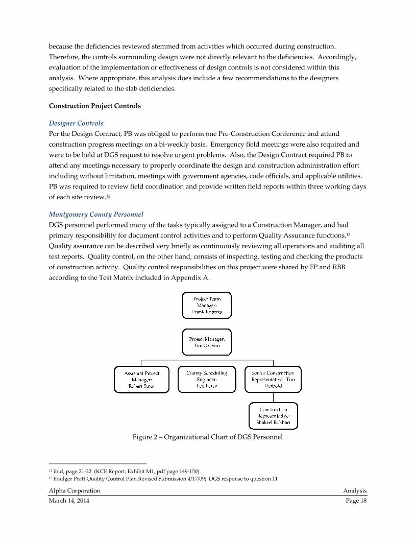
Montgomery County Personnel
DGS personnel performed many of the tasks typically assigned to a Construction Manager, and had
primary responsibility for document control activities and to perform Quality Assurance functions.13
Quality assurance can be described very briefly as continuously reviewing all operations and auditing all
test reports. Quality control, on the other hand, consists of inspecting, testing and checking the products
of construction activity. Quality control responsibilities on this project were shared by FP and RBB
according to the Test Matrix included in Appendix A.
Figure 2 – Organizational Chart of DGS Personnel
12 ibid, page 21‐22. (KCE Report, Exhibit M1, pdf page 149‐150) 13 Foulger Pratt Quality Control Plan Revised Submission 4/17/09; DGS response to question 11

Alpha Corporation Analysis
March 14, 2014 Page 19
Several DGS personnel were involved in the construction administration of the SSTC. A full description
of the duties and functions of each person as provided by DGS can be found in Appendix B. The
organization of personnel is summarized in Figure 2 on page 18 and was developed based on duty and
function descriptions from Appendix B. The organizational relationships were and continue to be in
effect throughout the duration of the construction activities.
Construction Manager
The Construction Management Contract was initiated after construction began to provide on‐site
construction project management services. The Background section of the Construction Management
Contract indicates that during the first part of the construction effort substantial redesign was
necessitated by large scale underground utility relocation and several unforeseen conditions. Due to the
significant delay relating to the redesign, Montgomery County determined it necessary to have a full‐
time project engineer from PB’s staff on‐site to coordinate the redesigns and review process activities.
John Anderson serves the role of onsite project engineer. The scope of services in the Construction Man‐
agement Contract indicate that Mr. Anderson’s responsibilities include coordination of project design
activities and issues with various outside agencies, production of required progress reports to outside
agencies, coordination of document reviews, documentation and assistance to DGS staff in negotiating
Construction Contract changes, identification and resolution of project design issues, participation in
progress meetings, and assistance to DGS’s Capital Projects Manager and other County personnel with
other duties that may be necessary to expedite and assure satisfactory coordination with WMATA and
other agencies involved in project.14
While the contract with PB was called a Construction Management Contract, responsibilities of Mr.
Anderson do not correlate to typical industry Construction Manager roles. Without an independent
Construction Manager engaged for the project, DGS was expected to function in the typical CM role,
which is described in an industry publication as “conducting periodic progress meetings, document
control, cost tracking and management, evaluation of payment requests, change order management,
quality management, schedule control, monitoring of Contractor’s safety efforts, commissioning and
generation of the punchlist.”15 Mr. Anderson was in a support staff position to DGS as they provided
construction management. Additional discussion relating to the role of Construction Manager can be
found in the Considerations section of this analysis.
Contractor Quality Control Plan
Provisions in the Design Contract require PB to include certain quality control provisions in the
Construction Documents. These provisions would require the Contractor to submit a Contractor Quality
Control (CQC) Plan.16 Review of the Plan FP submitted indicates that it identifies requirements for
personnel organization, document control, RFI procedures, submittal control, testing, phased inspections,
14 Agreement for On‐Site Project Engineering Services between Montgomery County, Maryland and P.B. Americas, Inc. for On‐Site
Construction Project Management Services for the Silver Spring Transit Center Contract No. 0363200005‐AA, page 2‐3. (KCE Report,
Exhibit M1, pdf page 298‐299) 15 An Owner’s Guide to Project Delivery Methods by the Construction Management Association of America, August 2012, page 15 16 Contract for Architectural/Engineering Services between Montgomery County, Maryland and Parsons Brinckerhoff Quade &
Douglas, Inc. for Design of Silver Spring Transit Center, County Contract #4504510121‐AA, page L3 – L‐15.
Alpha Corporation Analysis
March 14, 2014 Page 20
deficiency correction, commissioning, and material handling. Also included in the Plan is the inspection
processes including concealed elements of work, special inspections per the Montgomery County
Statement of Special Inspections, substantial completion inspections and final inspections. The CQC Plan
applies to aspects of the work both on‐site and off‐site. The primary focus is on the early identification
and resolution of potential problems before they impact the project. A more detailed description of the
CQC Plan is found in Appendix A.
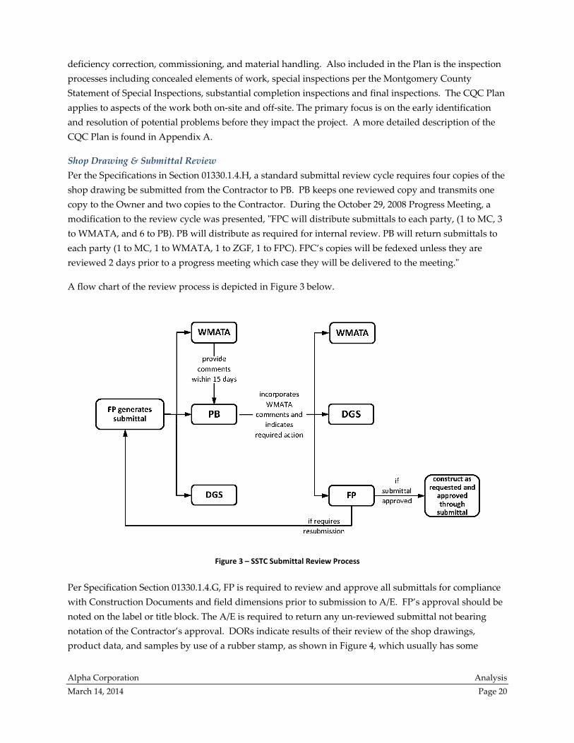
Shop Drawing & Submittal Review
Per the Specifications in Section 01330.1.4.H, a standard submittal review cycle requires four copies of the
shop drawing be submitted from the Contractor to PB. PB keeps one reviewed copy and transmits one
copy to the Owner and two copies to the Contractor. During the October 29, 2008 Progress Meeting, a
modification to the review cycle was presented, ʺFPC will distribute submittals to each party, (1 to MC, 3
to WMATA, and 6 to PB). PB will distribute as required for internal review. PB will return submittals to
each party (1 to MC, 1 to WMATA, 1 to ZGF, 1 to FPC). FPC’s copies will be fedexed unless they are
reviewed 2 days prior to a progress meeting which case they will be delivered to the meeting.ʺ
A flow chart of the review process is depicted in Figure 3 below.
Figure 3 – SSTC Submittal Review Process
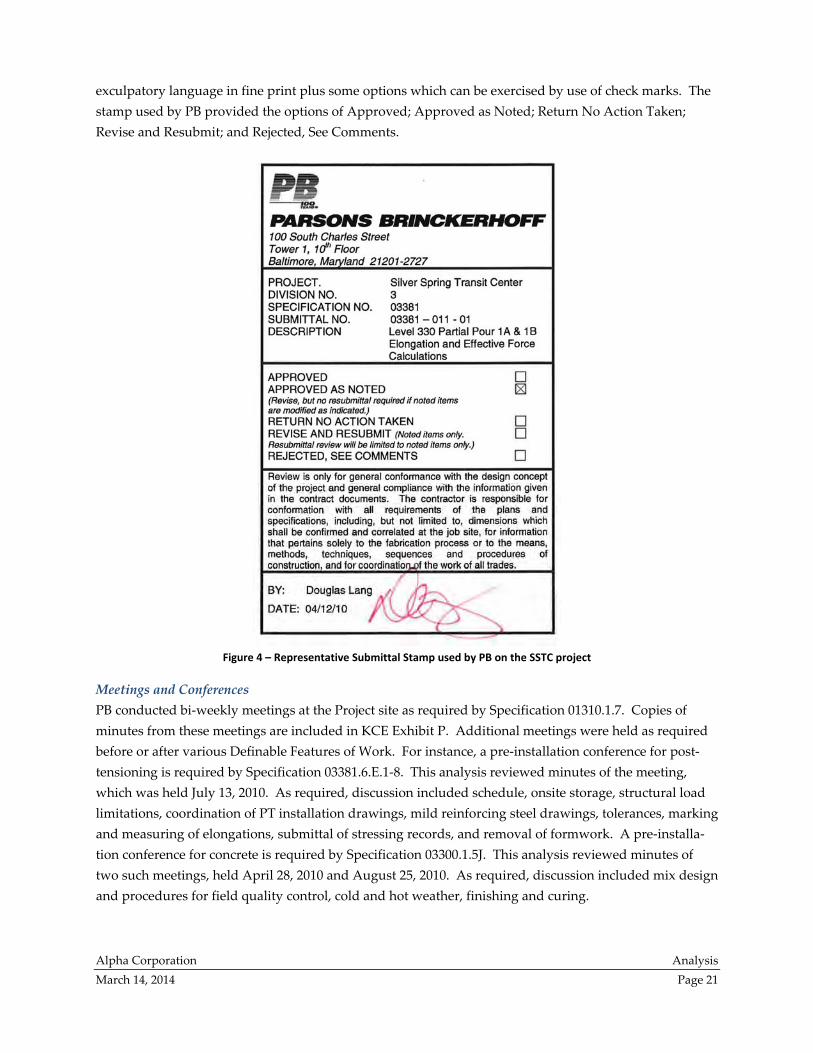
Per Specification Section 01330.1.4.G, FP is required to review and approve all submittals for compliance
with Construction Documents and field dimensions prior to submission to A/E. FP’s approval should be
noted on the label or title block. The A/E is required to return any un‐reviewed submittal not bearing
notation of the Contractor’s approval. DORs indicate results of their review of the shop drawings,
product data, and samples by use of a rubber stamp, as shown in Figure 4, which usually has some
Alpha Corporation Analysis
March 14, 2014 Page 21
exculpatory language in fine print plus some options which can be exercised by use of check marks. The
stamp used by PB provided the options of Approved; Approved as Noted; Return No Action Taken;
Revise and Resubmit; and Rejected, See Comments.
Figure 4 – Representative Submittal Stamp used by PB on the SSTC project
Meetings and Conferences
PB conducted bi‐weekly meetings at the Project site as required by Specification 01310.1.7. Copies of
minutes from these meetings are included in KCE Exhibit P. Additional meetings were held as required
before or after various Definable Features of Work. For instance, a pre‐installation conference for post‐
tensioning is required by Specification 03381.6.E.1‐8. This analysis reviewed minutes of the meeting,
which was held July 13, 2010. As required, discussion included schedule, onsite storage, structural load
limitations, coordination of PT installation drawings, mild reinforcing steel drawings, tolerances, marking
and measuring of elongations, submittal of stressing records, and removal of formwork. A pre‐installa‐
tion conference for concrete is required by Specification 03300.1.5J. This analysis reviewed minutes of
two such meetings, held April 28, 2010 and August 25, 2010. As required, discussion included mix design
and procedures for field quality control, cold and hot weather, finishing and curing.
Alpha Corporation Analysis
March 14, 2014 Page 22
Testing
Department of Permitting Services
As previously described, the Special Inspections Program for Montgomery County requires Special
Inspections (SI) to be performed on projects for verification of compliance of specific items listed on the
Statement of Special Inspections (SSI) which is a condition of the building permit. In the SSI, the SEOR
identifies those components that require special inspections, and names the inspection and testing agency
retained by the owner to perform the inspections. The Inspection Contract required RBB to perform the
third‐party testing.17 RBB was required to furnish copies of their inspection reports to the building
official at DPS within ten business days of each inspection.
Contractor
Administrative and procedural requirements for quality control and quality assurance are established in
the Specifications in Section 01400. The Section requires that FP engage an Independent Testing and
Laboratory Agency (different than the one utilized by the Owner) to provide inspection services not
specified as Owner’s responsibility. The section also references Section 01440, Contractor’s Quality Control
(CQC), which requires FP to submit a plan for execution of a CQC Program. As contained in Section
01440.3.7, Tests, FP is to perform tests to verify control measures are adequate to provide a product
conforming to Construction Documents. Contractor required testing is shown herein in the Testing
Matrix included in Appendix A.
The Special Inspections Program requires the Contractor to secure and deliver to A/E or its testing agency
samples of proposed material which are required to be tested, submit through the testing agency to the
A/E the proposed concrete mix design for approval, furnish labor as necessary to obtain and handle
samples, advise testing agency in advance of operations for completion of quality tests, and furnish
copies of mill test reports of all shipments of cement and reinforcing steel to Architect and testing agency.
Based on the documents reviewed, it appears the Contractor provided the appropriate submittals.
Testing Agency
Per the Specifications in Section 03300, Cast‐in‐Place Concrete, Paragraph 3.17 indicates field quality con‐
trol requirements for concrete work associated with the project. Subparagraph 3.17(A) indicates that the
Owner will engage a qualified testing and inspecting agency to perform test and inspections and prepare
test reports. Montgomery County entered into the Inspection Contract with RBB in accordance with the
Specification requirements. Section C of the Specification Section provides requirements for the concrete
testing including how the samples are to be obtained, frequency, which tests to perform on the samples,
how the tests are to be performed, how the testing results are to be communicated, what is considered to
be acceptable results, and what is required if testing indicates deficiencies. Slump, air content, concrete
temperature, and compressive‐strength tests are all required to be measured. Direction relating to slump
indicates that one test must be performed at point of placement for each composite sample. Direction on
location where samples must be obtained is not included for other tests.
17 Contract for Inspection and Materials Testing Services between Montgomery County, Maryland and The Robert B. Balter
Company, County Contract No. 6504510207‐AA, page 2. (KCE Report, Exhibit M1 pdf page 336).

Alpha Corporation Analysis
March 14, 2014 Page 23
For the compressive‐strength test, Section 03300 Subparagraph 3.17 (C)(6)(a) requires a test of one set of
two laboratory‐cured specimens at 7 days and one set of two specimens at 28 days. Additionally, one set
of two field‐cured specimens are to be tested at 2 days for evaluation of the concrete for acceptability to
begin post‐tensioning, one set of field specimens to confirm concrete placed in post‐tensioned members
has reached strength required for completion of stressing, and two cylinders for evaluation at 28 days to
compare to laboratory cured cylinders. The tests are to be performed in accordance with ASTM C 39.
The number of sets was expanded by mutual agreement during construction to include a set at 56 days.18
The Special Inspection Program documentation included in the Inspection Contract includes require‐
ments for testing of cast‐in‐place concrete as well as other components of a construction project. RBB was
required to perform slump tests; fabricating, sorting, transporting, curing, and testing of compression test
cylinders; test of fine and coarse aggregate; preparation and distribution of test and other pertinent
reports; review of mill test certificates for specification conformance; and report findings to Architect and
Contractor. The Program does not require RBB to test reinforcing steel, wire fabric, or mill tests on
cement and steel.19
Inspections
The Special Inspection Program requires inspectors to hold current certifications by the Maryland
Chapter of the American Concrete Institute or the Ready Mix Concrete Producers Technical Committee.20
Also, the inspectors must have a minimum of five years of experience in test inspection for construction
projects of similar scope and size.21 Per the Specifications in Section 03300, Cast‐in‐Place Concrete, Section
3.17 indicates field quality control requirements for concrete work associated with the project. Section A
indicates that the Owner will engage a qualified testing and inspecting agency to perform test and inspec‐
tions and prepare test reports. Montgomery County initiated the Inspection Contract in accordance with
the Specification requirements.
The Special Inspection Program documentation included in Exhibit E of the Inspection Contract includes
requirements for inspection of cast‐in‐place concrete as well as other components of a construction
project. Concrete structures require:
inspection of formwork and reinforcing prior to placement of concrete,
authorization in writing for the stripping of formwork and reshoring only after the criteria
approved by the Structural Engineer of Record (SEOR) is met,
inspection of the batching tickets and delivery operations for compliance with project
Specifications, and
performance of compression tests.
18 Item 4.2 in FP Preinstallation Conference minutes dated 4/28/2010 19 Contract for Inspection and Materials Testing Services between Montgomery County, Maryland and The Robert B. Balter
Company, County Contract No. 6504510207‐AA, Exhibit D, page 32. (KCE Report, Exhibit M1 pdf page 366). 20 ibid, Exhibit D, page 33. (KCE Report, Exhibit M1 pdf page 367). 21 ibid, Exhibit D, page 28. (KCE Report, Exhibit M1 pdf page 362).
Alpha Corporation Analysis
March 14, 2014 Page 24
Post‐tension concrete structures require:
inspections of formwork, tendons, and reinforcing prior to placement of concrete,
inspection of all concrete placement,
inspection of all tensioning,
retention of elongation records, and
provision of permission to Contractor to burn, cut, or cap pre‐stressing anchorage only after the
criteria approved by SEOR has been met.22
The Special Inspection Program documentation included in Exhibit D of the Inspection Contract indicates
that inspection of the plant (including batching) of all concrete and field inspection of concrete before,
during, and after placement is required. However, the design or inspection of formwork and the
supervision of the placing of reinforcing steel are excluded.23 SSTC Specifications delegate design and
implementation of formwork to the Contractor. The third‐party inspector RBB was required to inspect
the final placement of reinforcing steel, but not the day‐to‐day operations relating to placement.
Administrative and procedural requirements for quality control and quality assurance are established in
the Specifications in Section 01400. The section references Section 01440, Contractor’s Quality Control
(CQC), which requires FP to submit a plan for execution of a CQC Program. As contained in Section
01440.3.8, Substantial and Final Completion Inspections, when work or a designated portion thereof is
determined to be substantially complete by FP, then the CQC System Manager shall conduct an
inspection of the work and develop a “punch list” of items which do not conform to the approved plans
and Specifications. An additional inspection and list is also required at final completion. The Special
Inspection Program requires that the Contractor schedule and coordinate the required inspections such
that they are conducted and approved prior to proceeding with work.
Considerations
The report Managing the Design and Construction of Public Facilities: A Comparative Review (OLO Report)
prepared by the Office of Legislative Oversight (OLO) reviewed the management practices used within
Montgomery County Government and found that the practices largely align with the models and
practices used by other jurisdictions and with “best practice” literature.24 Elaboration on controls
discussed within the OLO Report and the presentation of additional future considerations for project
controls are discussed herein.
Construction Manager
The role of a Construction Manager (CM) can vary widely between construction projects so the scope of
CM services must be agreed by contract based on the owner’s needs. For the SSTC project, DGS had a
dedicated staff that performed many duties and functions (see Appendix B). Review of the Construction
Manager Contract for SSTC and the project description for the project engineer indicates that PB had a
limited role as CM and was engaged after problems arose in order for the Design Team to have addi‐
22 ibid, Exhibit E, page 46‐47. (KCE Report, Exhibit M1 pdf page 380‐381). 23 ibid, Exhibit D, page 32. (KCE Report, Exhibit M1 pdf page 366). 24 Managing the Design and Construction of Public Facilities: A Comparative Review, Office of Legislative Oversight, OLO Report
2013‐8, July 30, 2013, page i.

Alpha Corporation Analysis
March 14, 2014 Page 25
tional field presence during construction. It appears the additional field presence was intended to foster
more cohesive lines of communication between the Design Team and DGS field personnel, Contractor,
and other agencies involved/impacted by the project such as WMATA or utility providers.
As a clarification, the CM services provided by PB were handled separately from the same company’s
other roles in this project as DOR and SEOR. A single staff member, John Anderson, was assigned by PB
to fulfill their CM contract on the SSTC project. For the duration of CM activities, Mr. Anderson was
under the direct supervision of DGS project manager and had no decision making authority.25 A different
PB engineer, Douglas A. Lang, sealed the Construction Documents, reviewed shop drawings and
provided site observations as designer’s representative.
Examples of duties that, in general, can be handled by the CM are listed by the Construction Manage‐
ment Association of America in its publication Quality Management Guidelines.26 Of these items, DGS
took responsibility for: bid packaging and contracting strategy, permitting, public relations, and project
commissioning. Items that were delegated to FP include: master schedule, resource planning, and safety
considerations.
Of particular interest are items in which responsibility seems to have been shared between DGS and FP,
such as document control, because these items have the potential for contributing to confusion. At the
beginning of the project, DGS anticipated having “primary responsibility for document control activities.
These activities include tracking and obtaining responses to RFIs, submittals and proposals for extra
work from FPC, and maintaining an up‐to‐date set of Construction Documents.”27 The submittal logs
and RFI logs that are included in the record,28 however, were all contributed by FP. It was also FP who
maintained the up‐to‐date set of Construction Documents.29
The lack of clarity in project roles caused comment during review of the CQC submittal. “QA and QC
roles and responsibilities are split between [DGS], [RBB], [FP], and [FP]’s subcontractors, and the division
seems unclear to WMATA. WMATA doesn’t fully understand who is responsible for what. Any
confusion regarding roles and responsibilities can lead to lapses and mistakes, so this lack of clarity is
troubling.”30 Future projects would benefit from well‐defined allocation of responsibility between project
participants. Performance of project participants in each area of responsibility could be confirmed by an
independent agency carrying out the function of quality assurance. For example, if CM services are
obtained by contract from an independent organization, DGS can supervise the CM.
25 Memorandum dated June 16, 2009 attached to Construction Manager Contract (KCE Report, Exhibit M1, pdf page 309). 26 Page 6, 2000 edition, section contributor: Darryl Dunn of Construction Dynamics Group, Inc., Allentown, Pennsylvania. 27 Row 11 (Cont’d) of undated, tabulated responses by DGS to WMATA comments on the CQC plan submitted by FP. 28 Minutes from numerous PB Construction Progress Meetings (KCE Report, Exhibit series P). 29 June 14, 2010, email regarding Contract Drawings attached to RBB letter dated August 29, 2012 (for letter see KCE Report, Exhibit
Q1, pdf page 3) 30 Row number 1 of undated comments attached to the CQC plan submitted by FP.

Alpha Corporation Analysis
March 14, 2014 Page 26
Document Control
FP utilized Prolog Manager31 for RFI tracking and submittal tracking, with such logs usually included in
weekly progress meeting minutes.32 Minutes also include lists of action items, deficiencies, non‐
conformances, and drawing changes. Revisions were tracked using spreadsheets maintained by FP. Due
to the complexity of the project, a drawing log is a necessity to enable the entire project team to use the
same version of the Construction Documents. While it is beneficial to the team to have a Contractor who
is utilizing the latest edition of construction software, it is equally important for the Owner to have access
for use of the same documents.
Web‐based software programs such as Prolog Converge or Primavera Contract Management allow a records
custodian to maintain the document database on a real time basis and allow real time access by stake‐
holders across the project to these documents. In most cases an Owner can set restrictions to access to
these documents appropriate. An Owner has the option to request access into the Contractor web‐based
software (access could be granted as read only) or to maintain their own database which the Contractor
utilizes. For future projects, additional control can be obtained through the use of an Owner established
web‐based construction contract management database which is maintained by the Contractor or CM in
order to effectively manage the project’s administration, analysis, and reporting.
Shop Drawing Review
The PB approval stamp on shop drawings, such as in Figure 4 on page 21, were typically only applied to
the first (top) drawing of each set/batch of submitted shop drawings. Therefore, shop drawings that were
not the first drawing in a set/batch do not specifically bear evidence of PB approval, although the PB
stamp on the first page does list the other pages that were reviewed. While the application of the stamp
on the first drawing does not contradict Specification requirements, confusion may occur as to which
version of the drawing is the final, approved drawing. To avoid possible confusion, the requirement of
stamping each drawing could be incorporated into either future project specifications or into DGS Special
Inspection program. Stamping every drawing in a set is currently being implemented by many engineers
in the industry. Additionally with the advent of full size scanners, the loss of manpower due to the
repetition of stamping every sheet can be avoided by scanning and printing the shop drawings.
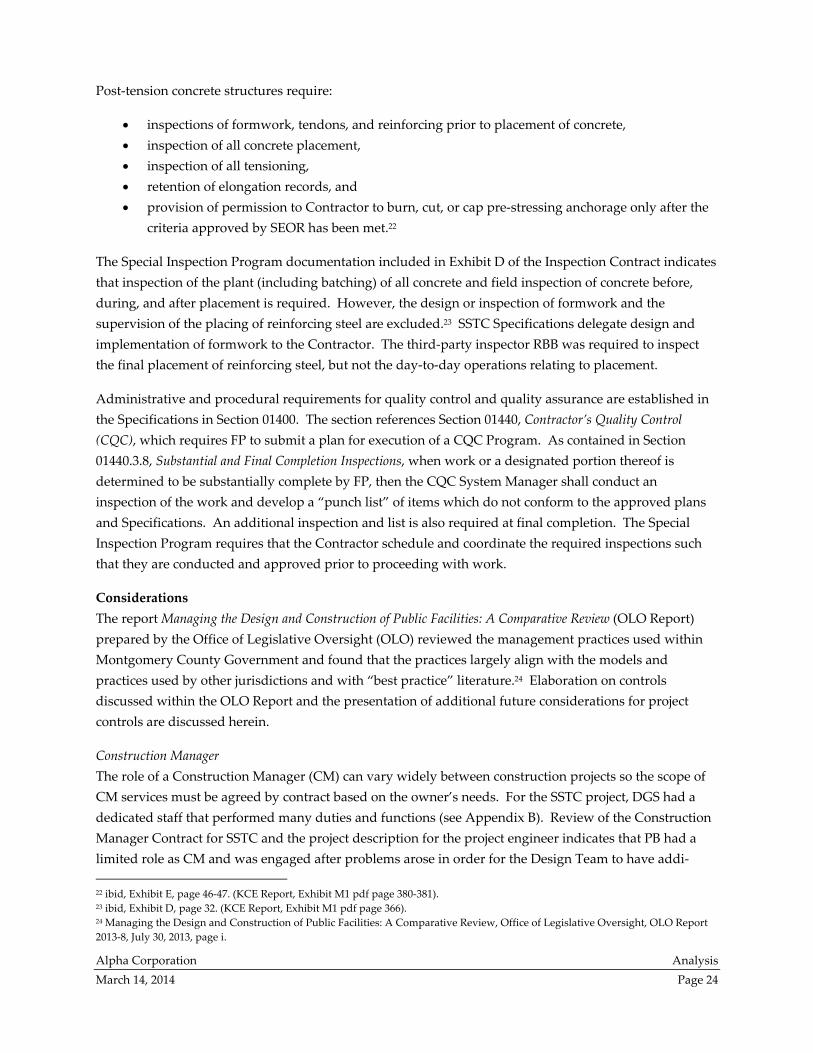
Additional project control can be obtained through the clear communication amongst all parties during
the submittal review process. Figure 5 on page 27 depicts a flow chart generally based on the submittal
review process implemented by a government agency to clearly define roles and responsibilities within
the submittal review process. Generation of a similar flow chart to identify and foster lines of
communication may be beneficial to DGS.
31 Prolog Manager is a construction project management computer application sold by Meridian Systems, a Trimble Company. 32 For an example, see PB Construction Progress Meeting #55, February 27, 2011 minutes. (KCE Report, Exhibit P4, pdf pages 10
through 17).
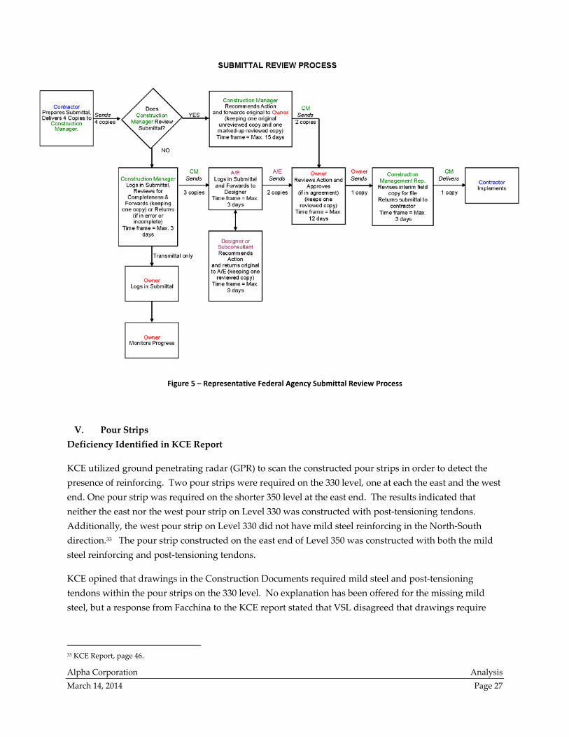
Alpha Corporation Analysis
March 14, 2014 Page 27
Figure 5 – Representative Federal Agency Submittal Review Process
V. Pour Strips
Deficiency Identified in KCE Report
KCE utilized ground penetrating radar (GPR) to scan the constructed pour strips in order to detect the
presence of reinforcing. Two pour strips were required on the 330 level, one at each the east and the west
end. One pour strip was required on the shorter 350 level at the east end. The results indicated that
neither the east nor the west pour strip on Level 330 was constructed with post‐tensioning tendons.
Additionally, the west pour strip on Level 330 did not have mild steel reinforcing in the North‐South
direction.33 The pour strip constructed on the east end of Level 350 was constructed with both the mild
steel reinforcing and post‐tensioning tendons.
KCE opined that drawings in the Construction Documents required mild steel and post‐tensioning
tendons within the pour strips on the 330 level. No explanation has been offered for the missing mild
steel, but a response from Facchina to the KCE report stated that VSL disagreed that drawings require
33 KCE Report, page 46.
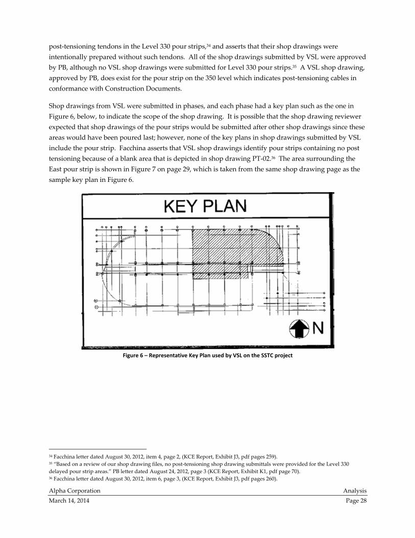
Alpha Corporation Analysis
March 14, 2014 Page 28
post‐tensioning tendons in the Level 330 pour strips,34 and asserts that their shop drawings were
intentionally prepared without such tendons. All of the shop drawings submitted by VSL were approved
by PB, although no VSL shop drawings were submitted for Level 330 pour strips.35 A VSL shop drawing,
approved by PB, does exist for the pour strip on the 350 level which indicates post‐tensioning cables in
conformance with Construction Documents.
Shop drawings from VSL were submitted in phases, and each phase had a key plan such as the one in
Figure 6, below, to indicate the scope of the shop drawing. It is possible that the shop drawing reviewer
expected that shop drawings of the pour strips would be submitted after other shop drawings since these
areas would have been poured last; however, none of the key plans in shop drawings submitted by VSL
include the pour strip. Facchina asserts that VSL shop drawings identify pour strips containing no post
tensioning because of a blank area that is depicted in shop drawing PT‐02.36 The area surrounding the
East pour strip is shown in Figure 7 on page 29, which is taken from the same shop drawing page as the
sample key plan in Figure 6.
Figure 6 – Representative Key Plan used by VSL on the SSTC project
34 Facchina letter dated August 30, 2012, item 4, page 2, (KCE Report, Exhibit J3, pdf pages 259). 35 “Based on a review of our shop drawing files, no post‐tensioning shop drawing submittals were provided for the Level 330
delayed pour strip areas.” PB letter dated August 24, 2012, page 3 (KCE Report, Exhibit K1, pdf page 70). 36 Facchina letter dated August 30, 2012, item 6, page 3, (KCE Report, Exhibit J3, pdf pages 260).
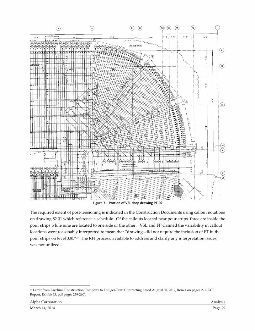
Alpha Corporation Analysis
March 14, 2014 Page 29
Figure 7 – Portion of VSL shop drawing PT‐02
The required extent of post‐tensioning is indicated in the Construction Documents using callout notations
on drawing S2.01 which reference a schedule. Of the callouts located near pour strips, three are inside the
pour strips while nine are located to one side or the other. VSL and FP claimed the variability in callout
locations were reasonably interpreted to mean that “drawings did not require the inclusion of PT in the
pour strips on level 330.”37 The RFI process, available to address and clarify any interpretation issues,
was not utilized.
37 Letter from Facchina Construction Company to Foulger‐Pratt Contracting dated August 30, 2012, Item 4 on pages 2‐3 (KCE
Report, Exhibit J3, pdf pages 259‐260).

Alpha Corporation Analysis
March 14, 2014 Page 30
Project Control Deficiencies contributing to this defect:
RFIs and Meetings
Questions regarding interpretation of the Construction Documents may be discussed at meetings or
answered via the RFI process.38 If the callout notation for locations of post‐tensioning tendons near pour
strips was confusing, then FP and their subcontractors had multiple opportunities to ask for clarification.
This project utilized regularly scheduled meetings to encourage communication, but the issue of post‐
tensioning in pour strips at Level 330 was not raised until the KCE Report findings were presented. The
methodology surrounding the RFI and meeting process was in conformance with Specification require‐
ments and is typical industry protocol. No deficiencies are noted in design or implementation of project
controls for RFIs and meetings. Adequate channels of communication were available to the Contractor,
although they were not utilized in regard to pour strip reinforcing.
Submittal Review
The CQC Plan directs that “the QC System Manager will certify contract compliance [of all submittals] or
note any variances.”39 The QC System Manager is another name for the CQC Manager that is discussed
in Appendix A of this document. In general, submittals are used to coordinate those details of a project
that are outside the scope of Construction Documents as well as present the Contractor’s understanding
of required construction. Design professionals review all submittals in order to check for conformance
with the design concept.
In addition to the review by the A/E, this project required FP to “review and approve all submittals for
compliance with Construction Documents and field dimensions.”40 The approval stamp from FP states,
“This submittal has been reviewed for general compliance with the plans and specifications. This review
and the response indicated below do not relieve the subcontractor or supplier of any contract
responsibilities including the furnishing of all items required by the documents and the confirmation of
all quantities and dimensions.” The stamp from Facchina certifies “that the specification requirements
have been met and all dimensions, conditions and quantities have been verified as shown and/or as
corrected in these drawings.”
The PB shop drawing review stamp says, “Review is only for general conformance with the design
concept of the project and general compliance with the information given in the construction documents.
The Contractor is responsible for conformation with all requirements of the plans and specifications,
including, but not limited to, dimensions which shall be confirmed and correlated at the project site, for
information that pertains solely to the fabrication process or to the means, methods, techniques,
sequences and procedures of construction, and for coordination of the work of all trades.” As commu‐
nicated by these review stamps, shop drawings are considered to integrate all relevant requirements of
Construction Documents and are intentionally used to direct construction efforts.
38 Item 1.8.A of Specification 01310 reads, “Immediately on discovery of the need for interpretation of the Contract Documents, and
if not possible to request interpretation at Project meeting, prepare and submit an RFI in the form specified.” 39 FP Quality Control Plan Revised submitted 4/17/09, item 3.D “Submittal Control,” page 11. 40 Item 1.4.G of Specification 01330

Alpha Corporation Analysis
March 14, 2014 Page 31
We noted that both mild steel shop drawings and post‐tensioning shop drawings were submitted in
multiple packages consisting of several drawings each, versus being submitted as one complete package.
There is no Construction Contract language or language in the Specifications which prevents FP from
submitting the shop drawings for a Definable Feature of Work in multiple submissions. It is possible that
phased submission of shop drawings contributed to the reviewers’ failure to notice the missing rein‐
forcing and tendons in the pour strips. For future projects, changes to submittal procedures should be
implemented to make it less likely that reviewers will fail to notice and correct omissions. For example,
requiring a log of anticipated submittals would improve detection of missing items. A requirement that
submittals associated with each Definable Feature of Work be delivered in one shipment should also
reduce this vulnerability but may not be practical in all cases.
In the case of the pour strips, mild steel reinforcing shop drawings show reinforcing for level 330 in the
East/West direction41 but not in the North/South direction42 at the west pour strip. At the east pour strip,
shop drawings show reinforcing in both the East/West43 and North/South44 directions. Mild steel
reinforcement in both directions is depicted in pour strip detail 10 of drawing S4.02 in the Construction
Documents. All shop drawings by Gerdau Ameristeel bear approval stamps from Facchina and from FP.
The shop drawings were approved as noted by PB. Approved shop drawings by Gerdau Ameristeel were
used to direct placement of mild steel reinforcing and were also the standard referenced by RBB
inspectors.
If the Contractor who prepared the post‐tensioning shop drawings believed that post‐tensioning should
not be included in the pour strips for level 330, the independent review by the QC manager should have
highlighted this difference from the Construction Documents and should have flagged it as a variance.
Since no variances were noted on the post‐tensioning submittal, the CQC manager’s initial review was
ineffective. The review of post‐tensioning shop drawings by PB also failed to detect this difference from
the Construction Documents.
The submittal review process was performed in accordance with the Contractor Quality Control Plan, the
Specifications and industry practice. Although further control, such as an additional review by another
individual, could be implemented to help guard against human error, that is not standard for the
industry. Design of the control for submittal review should have been adequate because it required two
independent reviews, and both reviews required by the control were implemented, but the control was
ineffective in the case of the pour strips because both reviewers failed to notice reinforcing omissions in
pour strips and PB failed to request clarification about whether a shop drawing for the pour strips was
forthcoming.
It should be noted that one page in the KCE copy of shop drawings still bears the mark “Revise and
Resubmit.” The page with this notation is Gerdau Ameristeel drawing R30‐1A‐2,45 which shows part of
41 Gerdau Ameristeel drawing R30‐1D‐1 (KCE Report, Exhibit Y5, pdf page 16). 42 Gerdau Ameristeel drawing R30‐1D‐2 (KCE Report, Exhibit Y5, pdf page 17). 43 Gerdau Ameristeel drawing R30‐1E‐1 (KCE Report, Exhibit Y5, pdf page 18). 44 Gerdau Ameristeel drawing R30‐1A‐2 and R30‐1E‐2 (KCE Report, Exhibit Y5, pdf pages 13 and 19). 45 KCE Report, Exhibit Y5, pdf page 13. Revise and Resubmit comment is dated October 7, 2009. A newer version of this drawing
with Approved as Noted comment dated March 29, 2010 was provided upon request.
Alpha Corporation Analysis
March 14, 2014 Page 32
the steel reinforcing in Pour 1A, adjacent to the east pour strip. Normally records should only include
approved versions, but this copy was included by KCE because their exhibits were intended to record
what was available to inspectors.
Inspections of work in progress based on unapproved drawings can lead to errors in the field. The EOR’s
comments on this particular drawing did not directly contribute to any of the deficiencies observed by
KCE, however an indirect connection could be construed with reinforcing missing from the west pour
strip. Only approved drawings should be utilized. FP was responsible for distribution of shop drawings
as described in Appendix A. Implementation of document control was deficient in the case of shop
drawing R30‐1A‐2.
Pre‐Installation Conference
A pre‐installation conference for post‐tensioning was held on July 13, 2010 to fulfill the Specification
requirements discussed in Section IV of this analysis. The methods and procedures discussed included
post‐tensioning mobilization (schedule, shop drawings, delivery and storage of materials), placement of
reinforcement and tendons in the slab (layout of formwork, rebar sequence, horizontal and vertical toler‐
ances and spacing) , stressing of tendons‐ inspections and testing (calibration, inspection and installation
coordination, stressing sequence and timing, elongation measuring, stressing procedures), grouting of
tendon duct (installation methods, testing, grout type), removal of formwork (timing, sequence), and
general safety.46 At the time of the pre‐installation meeting, not all shop drawings had been submitted
and approved.47 The shop drawings were submitted prior to each pour rather than submitted as a single
package. As a result, the pre‐installation conference for the post‐tensioning in its entirety was held prior
to approval of all shop drawings in their entirety. It is preferable that when practicable, all submittals
associated with a Definable Feature of Work be submitted in one shipment prior to pre‐installation meet‐
ings. If the Definable Feature of Work is extensive, then at a minimum a log of anticipated submittals
should be generated and reviewed at the pre‐installation conference.
Daily Reports
Daily reports do not mention any anomalies prior to placement of concrete in the pour strips. The Level
330 east pour strip was poured on January 12, 2011. The FP daily report from this date mentions “pour
strip between pours 1A & 1E” as work performed by Facchina.48 In advance of the concrete pour, the FP
daily report on January 11 has no mention of any preparatory meetings or discussions between FP and
Facchina. The RBB daily report for January 12 noted that ”Facchina placed approx. 50 cy of 8000 psi
concrete for pour strip between concrete deck pour 1A and 1E.”49
The Level 330 west pour strip was poured on April 19, 2011, and available evidence makes clear that the
Contractor and sub‐contractors were not aware of the deficiencies. Neither the FP daily report nor the
RBB daily report mention any concerns or deficiencies on the day of this concrete pour, while the April
18 report notes that “Facchina worked on cleaning and finishing up installing reinforcing steel for
46 SSTC Preparatory Meeting and Preinstallation Conference Meeting Minutes, 7/13/10. (KCE Report, Exhibit Q1, pdf page 7) 47 SSTC Preparatory Meeting and Preinstallation Conference Meeting Minutes, 7/13/10, Item 4.2. (KCE Report, Exhibit Q1, page 10.) 48 FP Daily CQC Report dated January 11, 2011 (KCE Report, Exhibit A4, pdf page 231). 49 RBB Daily Report by John Welk, 1/12/11. (KCE Report, Exhibit B5, pdf page 83).
Alpha Corporation Analysis
March 14, 2014 Page 33
concrete pour strip area 330 between concrete deck pours 1H and 1D. A final inspection was done for the
pour strip area and it was approved for concrete placement tomorrow 4‐19‐11 (Tues).”50
The quality control plan for this project includes the following list of instructions for deficiencies:51
Upon determination during any course of the work, or during any part of the three phased CQC
Inspection Process of the existence of a deficiency the following procedures will be followed:
Identification and documentation of the noted deficiency in the Contract Compliance
Notice Log.
Review of deficiency with Subcontractor or Supplier party to the deficiency.
Investigation of the cause of the nonconforming work. Documentation of any significant
findings.
Determination and documentation of corrective action.
Coordination and/or approval of corrective action as needed with Architect, Engineer,
and/or Owner.
Develop, implement and document procedures and/or controls to prevent recurrence by
having a new Initial Phase Inspection, re‐inspection to confirm and document adequacy
of corrective measures.
The above project control was not activated with regard to the pour strips because available evidence
indicates that the team believed that the mild steel layout indicated in the shop drawings was correct.
Workers and inspectors also had no reason to believe that there was post‐tensioning required to be
installed in the pour strip since post tensioning shop drawings did not exist. A comparison might be
made with the Level 350 pour strip, for which post tensioning was provided. Although the three pour
strips, two on Level 330 and one on Level 350, serve the same function and were built and inspected by
some of the same people, the width of the upper pour strip and the configuration of supporting girders
are different. SSTC is a complicated and unique project, so workers and inspectors would not have been
guided by intuition or experience. VSL, who has experience in similar structures,52 had to resubmit many
of their shop drawings after review by PB due to the complexity of the project. Therefore, no deficiencies
are noted in controls on daily reporting with regard to pour strips. However, some issues noted in RBB
daily reports are not documented to have received follow up. See the section of this analysis that
discusses unhydrated cement for more details.
[balance of page intentionally left blank]
50 RBB Daily Report by John Welk, 4/18/11. (KCE Report, Exhibit B6, pdf page 66). 51 FP Quality Control Plan Revised submitted 4/17/09, item 3.F “Phased Inspection and Deficiency Control,” pages 14‐15. 52 Facchina letter dated August 30, 2012, item 2, page 2, (KCE Report, Exhibit J3, pdf pages 259).
Alpha Corporation Analysis
March 14, 2014 Page 34
VI. Concrete Composition
Deficiencies Identified in KCE Report
Based on in‐situ sampling and testing performed by KCE, the concrete within the SSTC structure has
several deficiencies:
First, the concrete in some areas of the floors has lower compressive strength than required by
Construction Documents. The compressive strength is also lower than that reported by
construction period testing and sampling.
Second, petrographic analysis of coring samples taken by KCE indicates between 5‐12% of the
Portland cement and 16‐18% of the slag was unhydrated.
Third, petrographic analysis of coring samples taken by KCE indicates the presence of entrapped
air.
Lower compressive strength than is required by Construction Documents contributes to an inability of
the structure to support the intended loading. The deficiencies noted in the concrete composition also
provide evidence of concrete that had not gained sufficient strength at the time stressing of post‐
tensioning tendons occurred, which contributed to the excessive cracking visible in the slabs, beams and
girders.
Compressive Strength
KCE documentation includes results of laboratory testing of concrete sample cylinders obtained by RBB
during concrete pouring operations,53 which show that concrete compressive strength was tested per the
Specification requirements during construction. The documents reflecting RBB laboratory test results
indicate that the strength of the laboratory specimens exceeds the minimum value required in
Construction Documents.
However, results of the tests performed by KCE on the samples taken from the in‐situ concrete forming
the floors are less than required in the Construction Documents.54 The concrete compressive strength test
results on the samples obtained by KCE also show considerable variance, indicating to KCE that quality
control was insufficient.55 Discussion of the project controls relating to several aspects of concrete quality
follows.
Project Control Deficiencies
Pumped Concrete Samples
The purpose of a concrete pump is to move fresh concrete via hose from the truck chute (near the pump
hopper, at a fixed location) to the hose end, which may be easily moved as needed and is typically a great
distance away from the delivery truck. Through the use of a pump, all delivery trucks can unload at one
location and the concrete is efficiently distributed throughout the project. In order for the concrete to
53 KCE Exhibits R1 through R4. 54 KCE report, Table 4, page 40. 55 ibid, page 26.

Alpha Corporation Analysis
March 14, 2014 Page 35
move easily through the pump, lower viscosity helps as long as the concrete remains cohesive. Therefore,
it is not uncommon for workers to add water or chemical admixtures which improve these properties.
Excessive water in the mix has performance ramifications and should, therefore, be monitored closely.
Review of project documentation relating to the location where sample cylinders were to be created when
concrete is pumped indicated contradiction and ambiguity. The Inspection Contract56 and the Statement
of Special Inspection indicate that the sampling location should be the point of placement, which, during
pumping operations, is the discharge end of the hose. This does not agree with industry guidance from
ASTM. Specification section 03300.1.5.B references ASTM C 94 and that standard states that slump
samples should be taken from the point of delivery, which is the truck chute.
Meeting minutes from July 2010 indicate that the question was discussed during the pre‐installation
conference57 and at some point soon after RBB was directed to make a limited number of comparison
cylinders at the end of the concrete pump hose while conducting the majority of testing at the truck
chute.58 The minutes do not indicate who directed that course of action or why that direction was given.
Taking most of the samples at the truck chute increased the risk that the concrete samples taken would
not be representative of the in‐situ concrete. Since the contradiction between standards and Specifica‐
tions was raised in the appropriate forum, and since RBB documents indicate that testing followed the
protocol established therein, the control was implemented as directed. However, the control was weak‐
ened and failed to fully achieve its purpose. The design of this control should be clarified so that future
projects require testing at the point of placement, because air content and other properties can change
during pumping.
Inspection of Batch Plants
RFF provided the concrete for the floors from two of their batch plants.59 Batch plants are the location
where the components of concrete are dispensed into a ready mixed concrete truck. Batch plant inspec‐
tions are required as indicated in Section IV of this analysis. There are no specifics given as to what items
at the batch plant should be inspected. Inspections do not attempt to confirm the accuracy or calibration
of measurement devices used at the plant. Rather they are intended to confirm setup and maintenance in
accordance with industry standards and project specifications. An industry publication says, “While the
professional inspection does add to cost, the continuing education of the suppliers and concrete subcon‐
tractors in the areas of quality control should ultimately create better concretes of all strengths and result
in better and more economical use of materials.”60
56 Contract for Inspection and Materials Testing Services between Montgomery County, Maryland and The Robert B. Balter
Company, County Contract No. 6504510207‐AA, Exhibit D, page 34. (KCE Report, Exhibit M1, pdf page 368). 57 SSTC Preparatory Meeting and Preinstallation Conference Meeting Minutes, 7/13/10. (KCE Report, Exhibit Q1, pdf page 9). 58 RBB Letter regarding Response to KCE Report Dated March 15, 2013, April 22, 2013, page 7. “As directed by Montgomery
County and as agreed to by WMATA and PB at the pre‐pour meeting, [RBB] cast sets of 6 ‘comparison’ cylinders on the deck at the
end of the concrete pump hose.” 59 Item 1.8 in FP minutes reads “concrete will be shipped from both Rockville plant and the College Park plant,” Preparatory
Meeting 8/25/2010 regarding 03300 Concrete Placement Methods, Logistics, and Testing 60 ACI publication number 363‐R92 section 7.6, page 43.
Alpha Corporation Analysis
March 14, 2014 Page 36
RBB inspected the batch plant at Lafarge concrete in May of 2010,61 but batch plants belonging to RFF
were never inspected.62 PB meeting minutes from July of 2010 note that “concrete plant inspection can
occur anytime, [DGS] and [RBB] to coordinate a time.”63 Based on available documentation, the
inspection was not performed. The project control to inspect concrete batch plants was vague and was
not consistently implemented.
Batch plants owned by RFF are certified by the National Ready Mix Concrete Association.64 Certification
indicates that the batch plant maintains a documented quality management system and has been audited
by a third party independent of the batch plant. Aggregate moisture content is measured at least once
per each day of production and water addition to batches is adjusted accordingly. Measuring devices on
truck water tanks may be either sight gages accurate to ±1 gallon or water meters accurate to ±2%.
Procedures for verifying accuracy of measuring devices are described in the company’s quality manual.
Certification of RFF batch plants does not replace the inspection required by Specifications, but shows
that the concrete producer is in accordance with industry standard quality control measures.
Concrete Mix Design
Concrete is a mixture of Portland cement, water, aggregates, and admixtures. Combining water with
cement initiates a chemical reaction called hydration where the cement turns to paste and, in effect, glues
the aggregate together. The quantity of each component affects performance, so mixture formulations
must be customized to each application. Construction Documents give the required performance and
mandate that FP submit proposed mixes for PB review approval. The mix designs for each application
were submitted early in the project and discussed often at progress meetings.65
The concrete mix design used for the floors was identified on submittals and batch tickets as 8K2DC2NL.
The mix submittal was revised to address comments made by both PB and WMATA, after which it was
approved by PB. A modification of admixture quantities submitted by FP was approved separately by
PB. Since the mix was reviewed and approved by all parties required by Construction Documents and
according to industry practice, no deficiency is evident in implementation or design of the control for
approval of the concrete mix design.
Water to Cement Ratio
The ratio of water to cement (w/c) in concrete has a great influences on concrete’s behavior. A low water
to cement ratio yields a stronger, more durable mixture while a greater value allows for easier flow and
placement. KCE tested the w/c ratio in hardened samples taken from the in‐situ concrete and tabulated
the results in the KCE Report.66 Values for w/c ratio are expressed as a range or with a tolerance because
61 RBB Letter regarding Response to KCE Report Dated March 15, 2013, April 22, 2013, pages 168‐169. 62 RBB Letter regarding Response to KCE Report Dated March 15, 2013, April 22, 2013, page 8. “[RBB] requested inspection of
Rockville Fuel and Feedʹs plant several times, but authorization was never granted.” 63 PB Construction Progress Meeting #43, July 15, 2010 minutes. (KCE Report, Exhibit P3, pdf page 196). Item 3.1 of FP
Preinstallation Conference minutes dated April 28, 2010 is similar and reads, “Mike Bailey indicated there is a requirement for [RBB]
to inspect the concrete plant. John Hershey indicated any of us could call and come by anytime.” 64 Certificates from NRMCA were submitted with Concrete Mix Design Submittal. (KCE Report, Exhibit V1, pdf pages 73‐74). 65 Minutes from various PB Construction Progress Meetings. (KCE Report, Exhibit P2, pdf pages 29, 105, item 18.2 on pdf pages
154, 190 and 234), 66 KCE Report, Table 3, page 40.
Alpha Corporation Analysis
March 14, 2014 Page 37
they are estimates which are made based on evaluation of polished samples under microscopes.67 An
article in the ASTM Journal found that petrography estimates are routinely accepted by the concrete
industry.68 That same article gave four different methods upon which such estimates can be based, and
said there are few studies that can attest to the accuracy of the w/c ratio estimates. In all cases the w/c
ratio reported by KCE exceeds the value approved in the mix design. The petrographic test results
together with compressive strength test results suggest that water was added to the mixture without
documentation.
Motives for adding water to the mixture include pump protection and workability during placement.
The w/c ratio of fresh concrete cannot be directly tested, so the quantity of water added is controlled via
records from both the batch plant and the project site. These records are intended to control the three
locations where water can typically be added to concrete mixtures: at the batch plant, in the delivery
truck, or at the pump hopper.
Batch plants measure how much of each ingredient is used in every load, and a computer records these
quantities on the delivery ticket. The amount of water already present in wet sand or gravel is subtracted
from the amount of plain water provided. Often, batch plants purposefully provide less than the full
amount of water so that this “withheld” or “holdback” water can be added later to fine‐tune consistency.
The lower right‐hand corner of RFF delivery tickets indicates the amount of withheld water, which is the
maximum amount that is supposed to be added to the mixture at the project site. An example concrete
batch ticket is included in Appendix E – Sample Reports.
Ready mixed concrete trucks have a water reservoir used for cleanup which also provides water for
adjusting mixture consistency. The truck driver can dispense water into the mixer drum at the touch of a
button, which the driver is only supposed to do when authorized by the appropriate person. Available
documents do not clearly identify who was responsible for providing such authorization. KCE says “it is
generally the concrete superintendent” who determines if water is to be added (KCE Report, page 20).
RBB asserts that “the QC manager from [Facchina] directed the water to be added.”69 We were unable to
determine from documents reviewed whether or not all parties at the time of construction were aware
who had the authority to direct additive amounts.
Water meters on delivery trucks can range in simplicity from a clear tube mounted beside the water tank
to a digital meter mounted on the pipe leading to the mixer drum. This project used the clear tube type of
water level indicators. Field reports from RBB indicate how much water they observed being added to
the concrete mixture at the project site. A comparison of this number with the amount of withheld water
indicates that documented water additions at the project site were not in excess of allowed amounts on
67 “The water/cement ratio of the concrete was estimated by viewing a thin section of the concrete under an Olympus BH‐2
polarizing microscope at magnification up to 1000x. Thin section analysis was performed in accordance with APS Standard
Operating Procedure 00 LAB 013, ‘Determining the Water/Cement of Portland Cement Concrete, APS method.’ The samples are
first highly polished, then epoxied to a glass slide. The excess sample is cut from the glass and the slide is polished until the
concrete reaches 25 microns or less in thickness.” American Petrographic Services, Inc. report dated October 29, 2012, page 4 (KCE
Report, Attachment 47, pdf page 127). 68 Erlin, Bernard (2006). “Catching the Elusive Water‐Cement Ratio Using Petrographic Methods—and Their Evaluation.” Journal of
ASTM International, Volume 5, Issue 7. 69 RBB Letter regarding Response to KCE Report Dated March 15, 2013, April 22, 2013, page 7.
Alpha Corporation Analysis
March 14, 2014 Page 38
loads for which records exist. However records exist for only one in five trucks. It is assumed that batch
tickets for other trucks were discarded after review by RBB. It is helpful to retain all batch tickets through
completion of the project so that project records are complete. This is not standard practice, but easily
implemented for future projects.
RBB asserts that they also monitored “loads which were not sampled, to observe that the amount added
did not exceed the holdback amount.”70 The inspector recorded the amount of water he observed to be
added, so control of water additions to concrete mixes was implemented according to Specifications.
However, water additions by truck drivers can occur unnoticed by the inspector. Therefore, the design of
this control could be improved in future projects by specifying the use of meters on the water lines that
lead to mixer drums, not just level indicators on the water tank (which can also be used for cleaning
purposes). This is practical, and sometimes happens, although it is not yet standard.
Water additions at the pump hopper are not mentioned in the project documents, either to confirm or
refute this practice. Any water additions at the pump hopper would likely have been observed by the
RBB inspectors stationed nearby. Since these inspectors were confirming that water additions did not
exceed holdback amounts (as asserted above), it is expected they would have objected to such a practice.
The water additions implied by KCE’s petrographic evaluation are approximately 10 gallons per cubic
yard of concrete.71 It is highly unlikely that such a quantity could have been added at the pump hopper
without notice, or that such a quantity could be thoroughly mixed into the fresh concrete by the pump.
Water is sometimes added to the concrete surface during finishing. A soft surface layer72 was noted by
KCE petrographers in some cores,73 so water additions at the concrete surface may be one explanation for
the occurrence of a soft surface layer. However, it is possible for water to “bleed” to the surface of fresh
concrete, and such bleed water may explain the soft surface layer. Adding water during concrete finish‐
ing is never recommended because it decreases the durability of the surface layer. The addition of water
at the surface during finishing was discussed and declared unacceptable during the preconstruction
meeting.74 Concrete finishing includes the processes called screeding (which removes concrete from high
areas and fills in low areas), floating (which embeds large aggregate and moves a small amount of cement
paste upward) and either troweling or brooming (which provide a smooth or textured surface, respec‐
tively). Finishing operations do not deeply stir the concrete, so water additions at the surface would not
explain the w/c ratio found by KCE inside the concrete slabs.
70 RBB Letter regarding Response to KCE Report Dated March 15, 2013, April 22, 2013, page 6. 71 As shown on the RFF delivery ticket in Appendix D, the design W/(C+P) ratio was 0.26 and the design quantity of water at this
ratio was 31.0 gallons per cubic yard. To reach a ratio of 0.35 (the low end of the range reported by KCE), water content would have
to be: (31 gallons) x (0.35) / (0.26) = (41 gallons), a 10 gallon per cubic yard increase. 72 “The immediate top surface of the core samples is soft and easily removed rendering the surface lacking sufficient wear resistant.
The inferior paste properties observed surficially can be attributed to an elevated water‐cementitious materials ratio, possibly [due
to] applied water.” Universal Construction Testing, Ltd. report dated February 19, 2013, page 3 of 65 (KCE Report, Attachment 51,
pdf page 214). 73 “The water/binder ratio was approximately 0.35, but the 0.40 to 0.45 near the top surface which indicated more water at the
surface which could be a sign of re‐tempering.” RJ Lee Group report dated December 4, 2012, page 6 of 19 (KCE Report,
Attachment 51, pdf page 393). 74 Item 2.3 in FP minutes reads “No water used to aid in finishing. Eucobar finishing aid is approved,” Preparatory Meeting
8/25/2010 regarding 03300 Concrete Placement Methods, Logistics, and Testing.
Alpha Corporation Analysis
March 14, 2014 Page 39
Water additions without documentation are implied by KCE, who writes:75
We also believe the .24‐.26 range [of w/c ratio] is not consistent with the slumps as RBB
reported, presumably after a high range water reducer was added per the approved mix
design. In fact if the water/cement ratio was .24‐.26, it is our opinion the concrete would
have been very difficult to pump and even harder to finish and would not have
permitted complete hydration to occur.
Slump Measurements
The slump test is used on fresh concrete mixtures to measure workability. Slump measurements are
influenced by mixture proportions, water content, and admixtures. Water‐reducing admixture WRDA 35
and superplasticizer EXP 950 were approved on this job,76 and the quantity of each admixture added at
the batching plant was recorded under rows labeled WRDA and SUPER, respectively, in the RFF delivery
tickets (see Appendix E – Sample Reports). A low slump value indicates a stiff mixture while higher
values correspond to thinner mixtures. Slump measurement values were recorded by RBB once for every
50 cubic yards, in accordance with Construction Document requirements. The approved submittal limits
slump to 8 inches, and slumps were consistently within the range of 7 and 8 inches at slab pours. Since
documents indicate that slump limits are in accordance with the approved submittal, no deficiency in
control implementation relating to slump is noted. However, WMATA Specifications limit slump to 2 – 4
inches77 so the design of this control was inconsistent with WMATA requirements.
Unhydrated Cement
If concrete does cure not properly, cement in the mixture can remain unhydrated (uncombined with
water). Portland cement must combine with water in order to bind the other components together.
Ground blast‐furnace slag (an industrial byproduct that improves the strength and quality of concrete)
was combined with Portland cement on this job, so the term “cementitious materials” is used to refer to
all active ingredients. The presence of unhydrated cementitious material is attributed by KCE to delayed
placement and/or early removal of thermal protection during cold weather.78 The paragraphs that follow
discuss these ideas and present another possible source of unhydrated cementitious material.
Ambient temperature affects the chemical reaction between cement and water; therefore newly placed
concrete needs protection during cold weather. Cold weather is defined as a period when the average of
expected daily high and low temperatures falls below 40°F for three successive days. Specifications
provide limits on the temperature of delivered concrete and on surface temperatures for the next several
days. Documents indicate that these limits were not clear to project participants79 since the Specifications
reference ACI 306.1 for such limits. Photocopies attached to the cold weather meeting minutes are taken
from ACI 306R, the Guide to Cold Weather Concreting rather than the Specification for Cold Weather
Concreting. Tables in ACI 306R repeat some of the limits given in ACI 306.1, but other requirements are
75 KCE Report, page 22. 76 Concrete Mix Design Submittal, (KCE Report, Exhibit V1 pages 25 and 27). 77 WMATA specification 03300 section 3.02 C.1.c (KCE Report, Exhibit E1, pdf page 1115). 78 KCE Report, pages 23‐25. 79 Item 4.1 of FP preparatory meeting 03300 Cold Weather Concrete minutes dated 11/4/2010 reads, “Facchina believed the cold
weather protection requirement to be 3 days. Subsequent research of ACI leads the group to believe that 3 days cold weather cure
time is proper.”
Alpha Corporation Analysis
March 14, 2014 Page 40
not duplicated. Some details of cold weather protection were affected by this confusion in document
retrieval, resulting in incorrect implementation of the cold weather project control as discussed below.
Cold weather specification ACI 306.1 sets minimum surface temperature at 55°F while concrete is
protected, and also notes that temperature of fresh concrete is not to exceed the minimum by more than
20°F. WMATA Specifications provide for a minimum surface temperature of 55°F, with no upper limit.
Cold weather protection measures required by the Specifications were implemented by the Contractor for
eight of the floor pours. Plastic sheeting and blankets were placed on top surfaces just after the concrete
was poured, and the area below the pour was enclosed and heated. RBB monitored concrete surface high
and low temperatures at several locations. Based on RBB temperature readings,80 lower limits were
frequently exceeded in the days following placement of concrete for the floors. It may be that none of the
parties who reviewed RBB’s daily reports to DGS noticed that temperatures were outside of the range
allowed by the referenced standard.
Prevention of sudden temperature changes is also the reason for another limit in both ACI and WMATA
Specifications. ACI 306.1 Table 3.2.1 requires a gradual decrease in surface temperature limited to 50
degrees per day, while WMATA Specifications limit temperature drop to 20°F per day. A gradual
decrease in surface temperature cannot be confirmed on this project since RBB did not monitor concrete
temperatures after area heat was discontinued,81 which typically occurred after 3 days. Three days is the
minimum thermal protection period required by ACI 306.1 Section 3.4.4, while WMATA Specifications
require that curing protection should last 7 days.82
Controls for cold weather concrete as designed were less restrictive than WMATA Specifications. This
project should have clearly conveyed temperature limits during cold weather curing, and the duration of
these limits should have been coordinated with those set by WMATA. The Contractor should have
procedures for correcting any temperatures that were outside of these limits. The Construction Manager
should have taken action when temperatures measured by their Inspector exceeded project limits.
Another potential source of unhydrated cementitious material is drying. To limit water loss during
concrete finishing operations, Specification 03300 3.13.B indicates that evaporation retarding chemicals be
applied when “hot, dry, or windy conditions cause moisture loss approaching 0.2 pounds per square foot
per hour.” RBB asserts that evaporation retarding chemicals were used as specified,83 although RBB daily
reports do not discuss this topic. Eucobar, an evaporation retardant, was discussed before concrete
placement,84 and a representative from Eucobar visited the project.85 After concrete finishing,
Specification 03300 3.13.E requires one of three methods to prevent moisture loss: wet curing, moisture
retaining covers, or curing compounds. The use of moisture retaining covers was observed during cold
80 Various RBB Daily Reports, (KCE Report, Exhibit B4 pdf pages 391, 397, 405, 411 and 415 are related to pour 2B). 81 RBB Daily Report, 12/14/10. (KCE Report, Exhibit B4, pdf page 415). “Heat turned off under deck, stopped monitoring temps.” 82 WMATA specification 03300 section 3.06 B.1.c (KCE Report, Exhibit E1, pdf page 1123, KCE Report, Exhibit N2, pdf page 80). 83 RBB Letter regarding Response to KCE Report Dated March 15, 2013, April 22, 2013, page 5. 84 Item 2.3 in FP minutes reads, “No water used to aid in finishing. Eucobar finishing aid is approved.” Preparatory meeting held
August 25, 2010 regarding 03300 Concrete Placement Methods, Logistics and Testing. 85 “EUCOBAR rep onsite,” FP Daily CQC Report dated December 10, 2010 (KCE Report, Exhibit A4, pdf page 151).
Alpha Corporation Analysis
March 14, 2014 Page 41
weather,86 but RBB reports do not otherwise document the curing method used by Facchina. Implemen‐
tation of controls to prevent drying is poorly documented based on reviewed information. Design of
these controls is less restrictive than WMATA Specifications, which require wet curing except where
application of moisture would be impractical.87
A third potential source of unhydrated cementitious material is a type of drying called self‐desiccation.
Self‐desiccation can arise with mixtures having w/c ratios around 0.40 or less88 when the water initially
incorporated into the concrete is insufficient to completely hydrate all the cementitious materials. Self‐
desiccation can be prevented by using saturated, porous aggregate to provide internal curing. Since
internal curing was not specified on this project, the unhydrated cementitious material found by KCE
may be explained by self‐desiccation rather than by any construction deficiency. Indeed, low w/c ratio is
linked to unhydrated particles in one of KCE’s petrographic reports.89 The presence of self‐desiccation is
not detrimental to concrete as long as performance objectives such as strength, stiffness and durability are
met. For future projects, if the A/E believes that self‐desiccation will affect the structure’s performance,
project requirements should be modified to include internal curing.
Entrapped Air
Entrapped air was noted in some of the concrete samples taken from the in‐situ concrete by KCE.90 The
only project control on entrapped air given in the Construction Documents is a requirement for the
vibration of fresh concrete. One of the four RBB inspectors that were present during concrete pours
monitored concrete placement in the slab. In his report regarding pour 1B, an RBB inspector writes,
“Concrete was properly vibrated, 2 vibrators were used.”91 Based on this comment made early in the slab
pours, inspectors did verify that the vibration control was implemented.
The presence of entrapped air in the core samples is not surprising because an industry guide states,
“complete removal of entrapped air is rarely feasible.”92 Lack of additional project controls for entrapped
air does not indicate a deficiency in control design because monitoring and testing for entrapped air is not
possible. The same industry guide says, “Presently, there is no quick and fully reliable indicator for
determining the adequacy of consolidation of the freshly placed concrete. Adequacy of internal vibration
is judged mainly by the surface appearance of each layer.”93 Therefore, no deficiencies are noted in
controls relating to entrapped air.
86 “Slab was covered with poly sheets followed by insulated blankets.” RBB Daily Report by Tony Lord, 12/7/10, (KCE Report,
Exhibit B4, pdf page 384). 87 Item 3.05 of section 03300 (KCE Report, Exhibit E1, pdf page 1121). 88 American Concrete Institute, ACI 308R‐01, Section 1.3.2 (KCE Report, Exhibit Z1, pdf page 12). 89 “[Samples] show a superabundance of residual portland cement and slag particles evidencing restricted hydration as would be
anticipated due to the low w/cms.” Figure 13 in Petrographic Examinations of Cores from the SSTC dated February 14, 2013 by The
Erlin Company (KCE Report, Attachment 50, pdf page 204). 90 KCE Report, Table 16, page 70. 91 RBB Daily Report by Tony Lord, 10/02/10, (KCE Report, Exhibit B3, pdf page 847). 92 American Concrete Institute, ACI 309R‐96, Section 7.2. 93 American Concrete Institute, ACI 309R‐96, Section 7.6.2.
Alpha Corporation Analysis
March 14, 2014 Page 42
Entrained Air
Entrained air refers to microscopic cells of air distributed throughout the concrete paste. Entrained air
voids are much smaller than entrapped air, and are beneficial because they improve concrete’s resistance
to damage caused by freezing. The approved mix design required between 4 and 7 percent of entrained
air. The entrained air content in hardened cores taken from the in‐situ concrete on this project was
identified by KCE94 and in some cases was outside the approved range. Differences may be due to the
presence of a concrete pump, which can alter the air‐void system. However, apparent differences may
not be statistically significant due to the limited number of hardened samples which were evaluated and
the variability inherent in test methods. Also, the comparison of the post‐hardened values directly to
Construction Document requirements is disputed by another engineer.95
The entrained air content of fresh concrete was sampled by RBB once for every 50 cubic yards, in
accordance with Construction Documents. Batches with low air content were treated with Fritz‐Pak (an
approved96 admixture), and RBB asserts that the subsequent load or two were also tested.97 Pour
1Ea ʺshowed a pattern of low entrained air content spanning the majority of concrete sampled. For the
concrete trucks sampled this condition was rectified by the addition of air packs.ʺ98 The pattern of low
entrained air content was not recorded as an issue in the FP quality control log.99 The inspector
implemented testing for entrained air at the frequency given in Specifications, but the pattern of low
values thus detected was not dealt with as a deficiency according to the CQC plan. Design of controls on
entrained air is in accordance with industry standards, but implementation was deficient because it
lacked quality control.
The amount of entrained air at the point of concrete placement was only measured three times per floor
slab pour. Entrained air can be lost as concrete is conveyed through a pump,100 an effect that was not
quantified on this project. Air entrainment solutions used on future projects should take into account the
presence of a concrete pump.
VII. Concrete Placement
Deficiency Identified in KCE Report
The two deficiencies relating to concrete placement are concrete cover and thickness of the structural
floors. Based on GPR testing and coring samples by KCE, the required amount of concrete over
reinforcing (concrete cover) is not provided in some areas. In these areas, placement of reinforcing is not
94 KCE Report, Table 15, page 69. 95 “Technical specifications did not include performance requirements for air‐void characteristics of the hardened concrete, and the
technical specifications permitted concrete finishing techniques attributed by CTL [Group, Inc.] for the reduction of air in the near
surface.” by Simpson Gumpertz & Heger dated June 21, 2012, page 3, (KCE Report, Exhibit L1, pdf page 50). 96 Concrete Mix Design Submittal, (KCE Report, Exhibit V1 page 23). 97 RBB Letter regarding Response to KCE Report Dated March 15, 2013, April 22, 2013, page 10. 98 RBB Daily Report by Brian Flickinger, 11/12/10, (KCE Report, Exhibit B4, pdf page 264). 99 PB Construction Progress Meeting #52, December 9, 2010 minutes (KCE Report, Exhibit P3, pdf page 342). 100 “It is normal to find a loss of about 0.5 to 1.0 percent air as concrete is conveyed through a pump. … Certainly, air loss through a
pump doesnʹt occur every time. However, it does occur often enough to be considered seriously until better solutions are
developed.” Publication CIP 21, 2005, by the National Ready Mixed Concrete Association.
Alpha Corporation Analysis
March 14, 2014 Page 43
in accordance with Construction Documents or industry standards. The significance of this defect is
explained by KCE, who states, “The durability of a concrete structure is reduced as the depth of concrete
cover over reinforcement is decreased. This relationship is a result of the fact that there is a smaller
distance through which chlorides must penetrate to reach the depth of the reinforcing steel to initiate
corrosion.”101
Further, there are many locations where the thickness of the concrete floors does not meet the minimum
requirements as indicated in the Construction Document. The significance of this defect is explained by
KCE, who states, “Our analysis of the as‐built post‐tensioned slabs indicates slab areas with thicknesses
below approximately 9 inches and with compressive strengths at or below 6,970 psi do not have adequate
shear capacity in certain locations to support the design loads (the areas less than 9 inches thickness are
limited in extent and therefore do not limit overall load‐carrying capacity). In addition, the as‐designed
analysis indicates the initial and service level stresses were exceeded.”102
The insufficiency of concrete cover on tendons was identified as an issue on October 28, 2010 when three
ducts became exposed to view through the surface of Pour 1A shortly after being grouted.103 The Design
Team was immediately notified, and ʺnew procedures for tendon placement have been installed to
prevent them from surfacing after grouting/stressing.ʺ104 The new procedure105 helped, but not all tendon
cover values measured by KCE in slabs cast after this date met Construction Document provisions.106
Project Control Deficiencies
Post‐Tensioned Tendon Placement
Discussions during the post‐tensioned pre‐installation conference included vertical tolerance on tendon
placement.107 Checklists used by RBB before each pour included an item for “duct high and low points
(profiles) at the correct elevation with sufficient cover.”108 The engineer of record observed general
alignment of tendons a few days before at least nine of the pours.109 The efforts by various parties to
control tendon alignment did not prevent some cover deficiencies, but it is quite possible that insufficient
cover at tendons was caused by insufficient concrete thickness rather than by incorrect tendon placement.
Controls on location of post‐tension tendons, including pre‐installation meetings and pre‐pour checklists,
were implemented correctly, but did not prevent some popped tendons. No deficiency is noted in the
design of these controls since solutions were quickly created when problems arose.
101 KCE Report, page 97. 102 KCE Report, page 6. 103 RBB Daily Report by Tony Lord, 10/28/10. (KCE Report, Exhibit B4, pdf page 151). 104 PB Construction Progress Meeting #51, November 16, 2010, minutes (KCE Report, Exhibit P3, pdf page 317). 105 PB Field Observation Comments, 10/30/10. (KCE Report, Exhibit C1, pdf page 10). “the top of the duct should not be closer than 1
3/8 inch below the top of the slab. FP has made a template to check that this dimension is held.” 106 KCE Report, Attachment 33. 107 FP Preinstallation Conference Minutes, 7/13/2010. (KCE Report, Exhibit Q1, pdf page 8). 108 RBB Daily Report by Tony Lord, 12/3/10. (KCE Report, Exhibit B4, pdf page 369). 109 PB Field Observation Comments, various dates. (KCE Report, Exhibit C1).
Alpha Corporation Analysis
March 14, 2014 Page 44
Mild Steel Reinforcing Placement
RBB asserts that concrete clear cover was verified on mild steel reinforcing bars,110 although results of
such measurements were not documented in their reports. The concrete cover found by KCE at slab
bottom bars and at beams and girders meets requirements for fire ratings.111 (Wide variations found in
the cover of mild steel reinforcing at columns112 was not reviewed as part of this analysis.) Per Specifica‐
tion 03381.3.6D, reinforcing was to be secured against displacement, and an inspector verified that it was
not disturbed during concrete placement.113 Inspection of reinforcement placement which is required by
Specification 03300 3.17.B.1 was provided,114 although some inspections were possibly hurried based on
statements made in RBB daily reports.115 No deficiencies are noted in either implementation or design of
project controls on mild steel reinforcing bar locations.
Thickness of Concrete Floors
Thickness of concrete floors was not directly measured during concrete pours. The method selected by
the Contractor to establish floor thickness was to give the top surface the desired shape based on meas‐
urements taken by survey equipment operated while concrete was being placed.116 The bottom surface
was established by formwork positions. Thickness was realized as the difference between formwork and
top surface, with no redundant system to prevent floor thickness problems.
Slab thickness deficiencies were identified in portions of the incomplete project as early as November
2010,117 when less than half of the slab concrete had been placed. Thickness deficiencies were discovered
during the investigation into popped tendons, and WMATA immediately requested a survey to identify
other thin areas. WMATA’s survey was followed by other surveys,118 which show that thin areas also
110 RBB Letter regarding Response to KCE Report Dated March 15, 2013, April 22, 2013, page 5. 111 KCE Report, page 89. 112 KCE Report, page 48. 113 RBB Daily Report by Tony Lord, 10/18/10. (KCE Report, Exhibit B4, pdf page 7). ʺI monitored concrete placement on deck.
Tendons and reinforcing steel were maintained in their proper positions.” 114 Inspector Tony Lord (typical of multiple inspectors and occasions) writes, “I continued to inspect the placement w/ VSL and
structural drawings. I logged all items requiring correction that were found in my inspections. Placement is ongoing and will
continue tomorrow.” RBB Daily Report, 12/2/10. (KCE Report, Exhibit B4, pdf page 361). 115 RBB Daily Report by John Welk, 10/16/10. (KCE Report, Exhibit B3, pdf page 2). ʺWork & corrections were still not completed
today. Therefore sign‐off for concrete pour [1C] card was not done today. I will arrive @ 2:00 AM Monday morning 10‐18‐10 to do
final inspection of completed work, at which time, if all work is completed as per specifications, I will sign‐off on completed work
(concrete pour card).ʺ Records for pour 2A are missing after KCE Report, Exhibit B4, pdf page 201. RBB Daily Report by Tony
Lord, 11/11/10. (KCE Report, Exhibit B4, pdf page 256). ʺAt dayʹs end, placement was approx 90% complete. Placement [for pour
1Ea] is scheduled for tomorrow at 4 am. Concrete placement will begin in the areas where reinforcement has been
approved. Incomplete areas will be done ahead of concrete placement.ʺ RBB Daily Report by John Welk, 12/6/10. (KCE Report,
Exhibit B4, pdf page 376). ʺWork is still not completed. I will come in tonight @ 11:00 [PM] and do a final walk through inspection.
When work is completed I will sign‐off on pour card.ʺ Pour 2B was begun at 1:00 AM on 12/7/10. RBB Daily Report by John Welk,
12/9/10. (KCE Report, Exhibit B4, pdf page 393). ʺWork is still not completed. I will come in tomorrow morning @ 5:00 AM & do a
final walk through inspection. When work is completed I will sign‐off on pour card.ʺ 116 Entry 1.13 of FP minutes from meeting held 8/25/2010 regarding 03300 Concrete Placement Methods, Logistics and Testing:
“How will grades and elevations be established on finished concrete surface? Facchina’s surveyor/ layout man will shoot all
elevations of top of concrete as placed during the pour for use by W concrete to rake out and screed to established top of concrete
elevations.” 117 PB Construction Progress Meeting #51, November 16, 2010, minutes. (KCE Report, Exhibit P3, pdf page 317‐318.) “Area around
popped tendons was surveyed for slab thickness. Slab came in thin in some areas.” 118 Project Management Team Meeting #13, September 15, 2011 minutes item 6.1. “Slab Thickness Survey. WMATA’s survey was
confirmed by both MC’s surveyor and Faccina’s surveyor.”
Alpha Corporation Analysis
March 14, 2014 Page 45
exist in concrete placed following this discovery. The results of the Greenhorne thickness survey are
reproduced in Appendix C, which shows measured thickness by color code. The method selected by the
Contractor to establish thickness depended upon his own correct implementation. The inspector did not
(according to the response from RBB to the KCE report, the inspector could not) independently check
thickness except at the perimeter.119 However, wet depth checks using a simple rod inserted vertically
into the fresh concrete would have been practical. The engineer of record repeatedly included reminders
to “all parties” in comments noted in October and November 2010 field reports120 to maintain thickness,
but no independent method to check thickness was developed.
Construction Documents indicate several controls related to floor thickness:
Tolerance on finished floor elevation was required to be discussed in the concrete pre‐installation
conference as indicated in Specification section 03300.1.5J, but the topic is not found in this
meeting’s minutes.121
Specification section 03300.3.1B references ACI 117 for formwork tolerances, which sets a limit of ¾
inch on form surface elevations. The RBB checklist includes formwork shape, location, and
dimensions and RBB is listed among those testing correct installation of formwork in the FP Test/
Inspection Matrix122 (included as Appendix A of this analysis). However, the Inspection Contract
specifically excludes inspection of formwork,123 so it is unclear whether this tolerance was actually
verified.
Thus two project controls related to concrete thickness were not implemented, and concrete thickness
was not directly measured due to the construction method utilized. Future projects would benefit from
selecting a construction method that allows direct measurement of floor thickness, or at least from having
redundant verification of formwork and surface elevations.
VIII. Post Tensioning
Concrete is very strong in compression but easily cracks when loaded in tension, so reinforcing is
typically cast into it. Steel, which is strong in tension, is positioned where tensile forces are expected to
occur. The reinforcing can be conventional or an alternative is to reinforce concrete with high strength
steel strand, to which tension has been externally applied. When this tension is applied after the
surrounding concrete has hardened, the system is known as post‐tensioned concrete.
119 “Thickness of the slab at points away from the perimeter could not be measured without survey equipment.” RBB Letter
regarding Response to KCE Report Dated March 15, 2013, April 22, 2013, page 5. 120 PB Field Observation Comments, 10/15/10, 10/30/10, 11/11/10. (KCE Report, Exhibit C1, pdf pages 5, 8, 22) “Elevations of
formwork, system for maintaining required design elevations at the top of the concrete, and system for maintaining typical concrete
thickness at 10 inches should be verified by all parties.” 121 Item 6.1 in FP Preinstallation Conference minutes dated 4/28/2010 reads, “How will top of slab / thickness be determined? This
will be discussed at a future meeting.” The meeting held 8/25/2010 regarding 03300 Concrete Placement Methods, Logistics and
Testing did not discuss tolerances or thickness; surface profile in item 1.13 is the most similar item of discussion.
122 Foulger‐Pratt QC Plan‐Appendix E. 123 Contract for Inspection and Materials Testing Services between Montgomery County, Maryland and The Robert B. Balter
Company, County Contract No. 6504510207‐AA, Exhibit D, page 32. (KCE Report, Exhibit M1, pdf page 366).
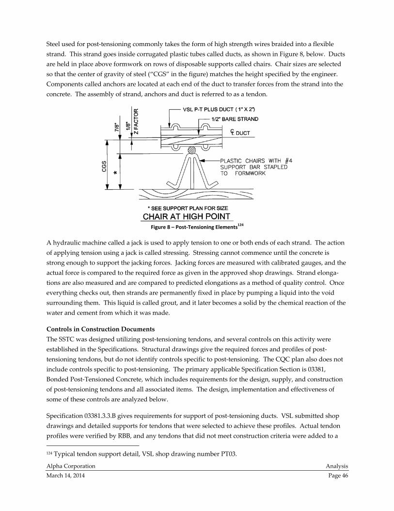
Alpha Corporation Analysis
March 14, 2014 Page 46
Steel used for post‐tensioning commonly takes the form of high strength wires braided into a flexible
strand. This strand goes inside corrugated plastic tubes called ducts, as shown in Figure 8, below. Ducts
are held in place above formwork on rows of disposable supports called chairs. Chair sizes are selected
so that the center of gravity of steel (“CGS” in the figure) matches the height specified by the engineer.
Components called anchors are located at each end of the duct to transfer forces from the strand into the
concrete. The assembly of strand, anchors and duct is referred to as a tendon.
Figure 8 – Post‐Tensioning Elements124
A hydraulic machine called a jack is used to apply tension to one or both ends of each strand. The action
of applying tension using a jack is called stressing. Stressing cannot commence until the concrete is
strong enough to support the jacking forces. Jacking forces are measured with calibrated gauges, and the
actual force is compared to the required force as given in the approved shop drawings. Strand elonga‐
tions are also measured and are compared to predicted elongations as a method of quality control. Once
everything checks out, then strands are permanently fixed in place by pumping a liquid into the void
surrounding them. This liquid is called grout, and it later becomes a solid by the chemical reaction of the
water and cement from which it was made.
Controls in Construction Documents
The SSTC was designed utilizing post‐tensioning tendons, and several controls on this activity were
established in the Specifications. Structural drawings give the required forces and profiles of post‐
tensioning tendons, but do not identify controls specific to post‐tensioning. The CQC plan also does not
include controls specific to post‐tensioning. The primary applicable Specification Section is 03381,
Bonded Post‐Tensioned Concrete, which includes requirements for the design, supply, and construction
of post‐tensioning tendons and all associated items. The design, implementation and effectiveness of
some of these controls are analyzed below.
Specification 03381.3.3.B gives requirements for support of post‐tensioning ducts. VSL submitted shop
drawings and detailed supports for tendons that were selected to achieve these profiles. Actual tendon
profiles were verified by RBB, and any tendons that did not meet construction criteria were added to a
124 Typical tendon support detail, VSL shop drawing number PT03.
Alpha Corporation Analysis
March 14, 2014 Page 47
pre‐pour checklist. Each item on the checklist was initialed after being corrected, prior to placement of
concrete. In spite of these efforts, a few popped tendons did occur (that is, the post‐tensioning ducts
became visible when the concrete cover cracked off and fell away). Popped tendons and controls on post‐
tensioned tendon placement are discussed in the Concrete Placement section of this analysis. Please see
that section for an evaluation of the control’s effectiveness.
Stressing Records
Specification 03381.1.4.A indicates that the Contractor is to “provide effective forces and profiles shown
on the drawings.” VSL submitted shop drawings that detailed tendons selected to achieve the required
effective forces. The effective force is distinct from the force applied by the stressing ram to the tendon
because some of the applied force dissipates. Loss of stressing force occurs both immediately (due to
elastic shortening, friction, and anchorage slip) and over the life of the structure (due to creep, shrinkage,
and relaxation). Effective forces were calculated by VSL engineers taking into account the expected sum
of all these losses. The results of these calculations were provided to field crews before post‐tensioning
operations in the form of expected elongations for each tendon.
Specification 03381.1.5.J indicates the elements to be included in stressing records. Stressing records
having the requested elements are included in KCE Exhibits C, D and H. Specification 03381.3.7.H
indicates that the stressing records are to be submitted and that elongations that deviate from the
expected value by more than 5 percent should be resolved to satisfaction of the EOR. This tolerance was
modified by PB during construction to plus or minus 7 percent,125 which is the tolerance given for post‐
tensioned construction in section 18.20.1 of the ACI 318 concrete building code.
Sometimes the actual elongations were outside allowable tolerances.126 Each such instance was evaluated
by the responsible engineer at VSL, and associated calculations were submitted to PB and are included in
Exhibit H of the KCE report. Out‐of‐tolerance elongations were reviewed by PB, and records of approval
are also included in Exhibit H. For example, one such evaluation is found in Exhibit H4 page 100, where
regarding pour 1A girders PG‐26 and PB‐39A, PB writes, “Final effective post‐tensioning force of 1363
kips has been calculated by VSL. This effective force is lower than the 1450 kip effective force identified
for these members in the Construction Documents (ASI #11), however, the members noted will still have
a capacity that is more than adequate for the design loading. Based on the final effective forces
determined by VSL, and PBʹs review of the design, I recommend that the post‐tensioning of these
members be accepted.” No deficiency is noted in the design, implementation, or effectiveness of the
control on stressing records.
Concrete Stresses
Stress in concrete is typically calculated rather than measured. The calculation starts with the forces
acting on a structural element, and then divides by the area of that element. A large force on a large
element may thus cause the same stress as a small force on a small element. The greatest stress is caused
by large forces acting on small elements.
125 RFI number 657 dated November 10, 2010 (KCE Report, Exhibit U3, pdf page 699). 126 KCE summarized elongation results in attachment 55 to the KCE Report, beginning in Volume 3 on pdf page 473.
Alpha Corporation Analysis
March 14, 2014 Page 48
Structural elements can experience different forces on opposite sides, for example compression on the top
and tension on the bottom. In these cases, somewhere between the two sides there is always a dividing
line at which there is neither compression nor tension. This line is called the neutral axis. The part of the
element that is farthest away from the neutral axis is called the extreme fiber. Building codes limit the
stress at the extreme fiber because that is the place on the element where cracks begin to form, thus
decreasing the strength and durability of the element.
Specification 03381.1.4.C indicates, “Comply with ACI 318 limits on stresses at transfer of prestress and
under service load.” Stress limits at the time of post‐tensioning are found in section 18.4.1 of ACI 318,
which says that the extreme fiber stress is not to exceed 0.60fci’ in compression or 3√fci’ in tension. Under
service loads, ACI 318 section 18.4.2 limits compression stress to 0.45fc’ while section 18.3.3 creates a
serviceability group for concrete with tensile stress of less than 7.5√fc’. WMATA is more restrictive than
ACI at service loads, limiting tension stress to 6√fc’.127
To check whether these limits are met, one must calculate the concrete extreme fiber stress. This calcu‐
lation is complex in post‐tensioned members and is usually done only by the engineer who designs the
post‐tensioned building elements. For the SSTC, PB provided the member sized and specified reinforcing
geometry. Engineers from VSL selected the tendons needed to achieve the effective forces specified by
PB and evaluated stressing operations.
Since decisions by PB controlled the extreme fiber stress, it seems misplaced for them to place a control on
concrete stress in the SSTC Specification. Sample specifications for post‐tensioned concrete structures as
produced by MasterSpec® contain a provision worded very similar to Specification 03381.1.4.C, but the
context of these sample specifications is for buildings in which the design services have been delegated to
a specialty engineer. Since design services were not delegated to the Contractor, inclusion of a
Specification provision providing limits on concrete stresses may have been inadvertent. The design of
this control is questionable because it delegates a check that PB should have performed.
KCE observes that, “Review of the Contract Documents and the PB calculations presented show that PB
attempted to comply with WMATA’s 6√f’c extreme fiber tension stress limit for service loads. However,
no initial stress review appears to have been performed.”128 The success of these attempts was challenged
in the structural investigation by outside engineer Simpson Gumpertz & Heger.129 No documentation is
found that any member of the Construction Team performed the calculations necessary to implement the
control on concrete stresses given in Specification 03381.1.4.C. The ineffectiveness of this control may be
responsible for some of the cracking observed in the SSTC. KCE notes that exceeding the initial extreme
fiber stress limit “could lead to concrete cracking during initial stressing. The initial cracking would affect
the distribution of service level stresses, but does not impact the ultimate strength of the structure.”130
127 Section 5.09.C.3.a.3 of the WMATA Manual of Design Criteria. (KCE Report, Exhibit E1, pdf page 331). 128 KCE Report, page 33. 129 “We analyzed PB’s original structural design using ADAPT‐PT 2010 (Build 2010.2) with PB’s input load files. We found service
level stresses exceeded PB’s stated 6√f’c criteria with the specified compressive strength of 8,000 psi.” by Simpson Gumpertz &
Heger dated March 14, 2012, page 6, (KCE Report, Exhibit L1, pdf page 14). 130 Ibid.
Alpha Corporation Analysis
March 14, 2014 Page 49
Grout Strength
Specification 03381 sections 2.5 and 2.10 give requirements for the grout inside of ducts, and provide
restrictions in addition to those in ACI 318 section 18.18. Strength is supposed to be 8,000 psi at 7 days,
which apparently was not always obtained based on meeting minutes from the post tensioning summit
held in November 2010.131 KCE Exhibits do not include sufficient documentation of grout strength break
results to evaluate the control’s effectiveness. Specification 03381 Sections 3.9 and 3.10 give grouting
requirements, with the frequency of sampling modified by RFI 624.132 Records indicating that grout
strength specimens were created are included in the KCE Exhibits, and it is apparent that PB reviewed
results of these tests because they authored a letter recommending acceptance of grout strengths.133
Independent evaluation of control effectiveness is limited by access to records.
Time to Grouting
During the post‐tensioning preparatory meeting, “it was discussed that the expected maximum time limit
to grout tendons after placement is 30 days. If tendons are left ungrouted after 60 days VSL can apply a
corrosion inhibitor product into the duct.”134 The Specifications do not provide any limit on time before
grouting. An industry guide suggests 20 days as the permissible interval between tendon installation and
grouting unless corrosion protection is used.135 Grouting operations were initiated 39 days after the first
pour, and grouting equipment broke immediately136 and repeatedly.137 By 46 days after the first pour, all
but a “small section of pour 1A not under pour 2A”138 had been grouted, with six blocked tendons
grouted after 88 days.139 Both the grout and the slab required external heat sources for pours 1C and
1D.140 No explanation was noted for the delay of grouting tendons at other pours, which have elapsed
times as shown in Table 2, below. No records were found documenting the use by VSL of the corrosion
131 Item 1.13 in PB minutes reads, “Monitor closely next grouting operation to ensure proper mixing and sampling is taking place –
concern about low 28‐day breaks,”and item 1.16 reads, “Facchina to evaluate why grout numbers are coming in low,” post
tensioning summit held November 30, 2010 (KCE Report, Exhibit C1 page 29). 132 RFI number 624 dated October 18, 2010 (KCE Report, Exhibit U3, pdf page 538). “One test is to be taken at the beginning of the
mixing of grout each day, every 2 hours during the operation, and at the conclusion of grouting each day.” 133 “The purpose of this letter is to confirm that Parsons Brinkerhoff has reviewed the grout strength comparison test results
performed on three batches of post‐tensioning duct grout.” Letter dated February 4, 2011 from Douglas A. Lang to Timothy
O’Gwin. (KCE Report, Exhibit B5, pdf page 289). 134 Item 4.2 in FP minutes, Preparatory Meeting 7/13/2010 regarding 03381 Bonded Post Tensioned Concrete (KCE Report, Exhibit Q
page 10). 135 Post‐Tensioning Manual, sixth edition by the Post‐Tensioning Institute (2006), Table 4.7 (page 86). 136 RBB Daily Report by Brian Flickinger, 10/22/10. (KCE Report, Exhibit B4, pdf page 93). “The 1st mixer/pump used ceased to
operate after 1 hour. Inspector informed of a clog in mixer at pump inlet. 2nd mixer attempted to be placed in service and inspector
informed that this mixer is in a non‐functional state.” 137 RBB Daily Report by Brian Flickinger, 10/26/10. (KCE Report, Exhibit B4, pdf page 112). “Grout placement for post tensioned
elements of concrete pour 1A resumes today… mixing equipment again clogged then broken in afternoon about 4pm.” RBB Daily
Report by Brian Flickinger, 10/29/10. (KCE Report, Exhibit B4, pdf page 186). “Grout operations started early in the afternoon, the
delay caused by the contractors primary grout mixer/pump having ceased functionality, and the contractors back up mixer/pump
being long term inoperative.” 138 RBB Daily Report by Brian Flickinger, 10/29/10. (KCE Report, Exhibit B4, pdf page 186). 139 RBB Daily Report by John Welk, 12/10/10. (KCE Report, Exhibit B4, pdf page 399). “Contractor also resumes grouting operation
for (6) blocked PT tendons for pour 1A, level 330’.” 140 RBB Daily Report by Brian Flickinger, 1/11/11. (KCE Report, Exhibit B5, pdf page 75). “Today’s grouting is started in morning
due to overnight heating of deck sections 1C and 1D, and the heating of materials to bring temperature of liquid grout and
surrounding concrete up to spec’s required for job. Without these heating efforts grout placement could not have been able to be
accomplished within job specs today.”
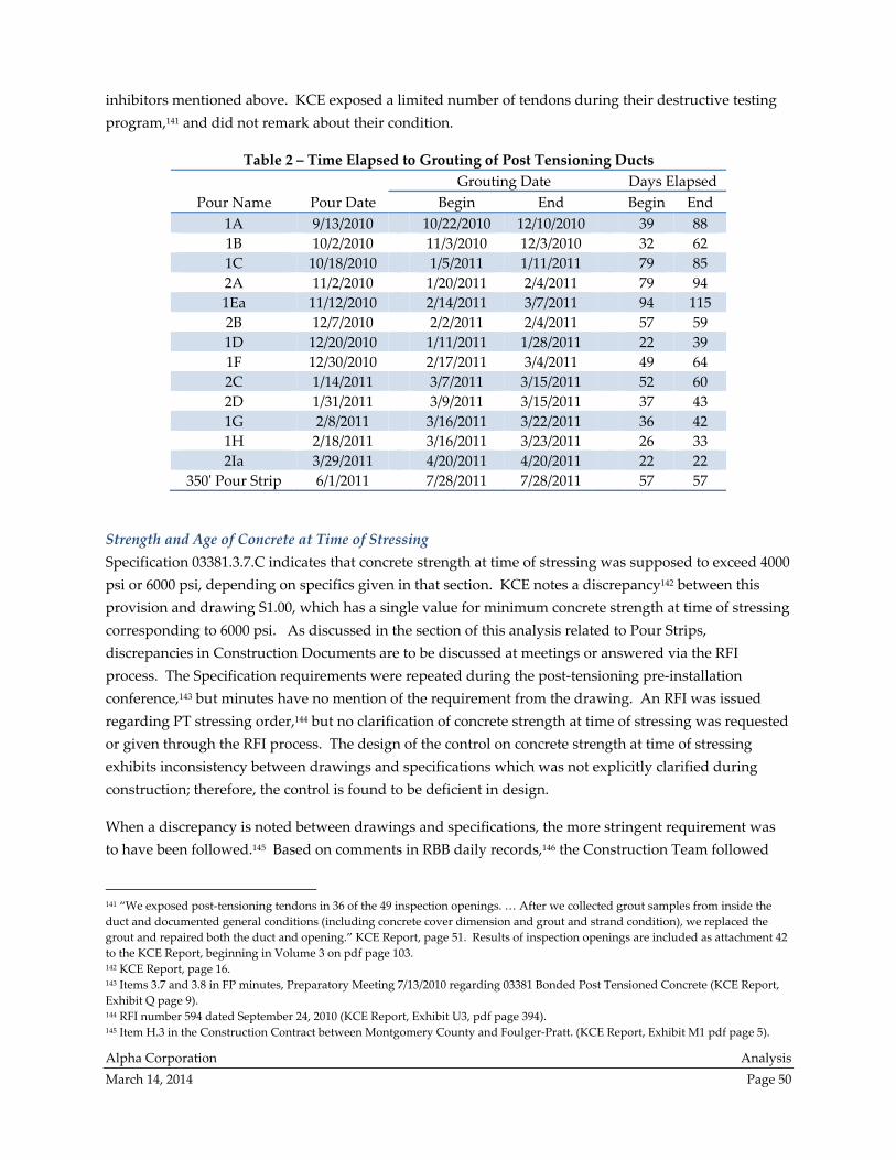
Alpha Corporation Analysis
March 14, 2014 Page 50
inhibitors mentioned above. KCE exposed a limited number of tendons during their destructive testing
program,141 and did not remark about their condition.
Table 2 – Time Elapsed to Grouting of Post Tensioning Ducts
Pour Name Pour Date
Grouting Date Days Elapsed
Begin End Begin End
1A 9/13/2010 10/22/2010 12/10/2010 39 88
1B 10/2/2010 11/3/2010 12/3/2010 32 62
1C 10/18/2010 1/5/2011 1/11/2011 79 85
2A 11/2/2010 1/20/2011 2/4/2011 79 94
1Ea 11/12/2010 2/14/2011 3/7/2011 94 115
2B 12/7/2010 2/2/2011 2/4/2011 57 59
1D 12/20/2010 1/11/2011 1/28/2011 22 39
1F 12/30/2010 2/17/2011 3/4/2011 49 64
2C 1/14/2011 3/7/2011 3/15/2011 52 60
2D 1/31/2011 3/9/2011 3/15/2011 37 43
1G 2/8/2011 3/16/2011 3/22/2011 36 42
1H 2/18/2011 3/16/2011 3/23/2011 26 33
2Ia 3/29/2011 4/20/2011 4/20/2011 22 22
350ʹ Pour Strip 6/1/2011 7/28/2011 7/28/2011 57 57
Strength and Age of Concrete at Time of Stressing
Specification 03381.3.7.C indicates that concrete strength at time of stressing was supposed to exceed 4000
psi or 6000 psi, depending on specifics given in that section. KCE notes a discrepancy142 between this
provision and drawing S1.00, which has a single value for minimum concrete strength at time of stressing
corresponding to 6000 psi. As discussed in the section of this analysis related to Pour Strips,
discrepancies in Construction Documents are to be discussed at meetings or answered via the RFI
process. The Specification requirements were repeated during the post‐tensioning pre‐installation
conference,143 but minutes have no mention of the requirement from the drawing. An RFI was issued
regarding PT stressing order,144 but no clarification of concrete strength at time of stressing was requested
or given through the RFI process. The design of the control on concrete strength at time of stressing
exhibits inconsistency between drawings and specifications which was not explicitly clarified during
construction; therefore, the control is found to be deficient in design.
When a discrepancy is noted between drawings and specifications, the more stringent requirement was
to have been followed.145 Based on comments in RBB daily records,146 the Construction Team followed
141 “We exposed post‐tensioning tendons in 36 of the 49 inspection openings. … After we collected grout samples from inside the
duct and documented general conditions (including concrete cover dimension and grout and strand condition), we replaced the
grout and repaired both the duct and opening.” KCE Report, page 51. Results of inspection openings are included as attachment 42
to the KCE Report, beginning in Volume 3 on pdf page 103. 142 KCE Report, page 16. 143 Items 3.7 and 3.8 in FP minutes, Preparatory Meeting 7/13/2010 regarding 03381 Bonded Post Tensioned Concrete (KCE Report,
Exhibit Q page 9). 144 RFI number 594 dated September 24, 2010 (KCE Report, Exhibit U3, pdf page 394). 145 Item H.3 in the Construction Contract between Montgomery County and Foulger‐Pratt. (KCE Report, Exhibit M1 pdf page 5).
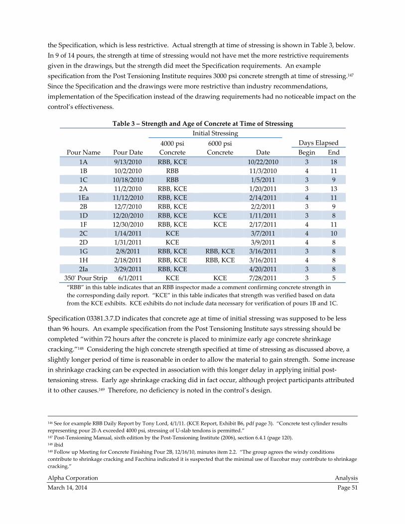
Alpha Corporation Analysis
March 14, 2014 Page 51
the Specification, which is less restrictive. Actual strength at time of stressing is shown in Table 3, below.
In 9 of 14 pours, the strength at time of stressing would not have met the more restrictive requirements
given in the drawings, but the strength did meet the Specification requirements. An example
specification from the Post Tensioning Institute requires 3000 psi concrete strength at time of stressing.147
Since the Specification and the drawings were more restrictive than industry recommendations,
implementation of the Specification instead of the drawing requirements had no noticeable impact on the
control’s effectiveness.
Table 3 – Strength and Age of Concrete at Time of Stressing
Pour Name Pour Date
Initial Stressing
Days Elapsed 4000 psi
Concrete
6000 psi
Concrete Date Begin End
1A 9/13/2010 RBB, KCE 10/22/2010 3 18
1B 10/2/2010 RBB 11/3/2010 4 11
1C 10/18/2010 RBB 1/5/2011 3 9
2A 11/2/2010 RBB, KCE 1/20/2011 3 13
1Ea 11/12/2010 RBB, KCE 2/14/2011 4 11
2B 12/7/2010 RBB, KCE 2/2/2011 3 9
1D 12/20/2010 RBB, KCE KCE 1/11/2011 3 8
1F 12/30/2010 RBB, KCE KCE 2/17/2011 4 11
2C 1/14/2011 KCE 3/7/2011 4 10
2D 1/31/2011 KCE 3/9/2011 4 8
1G 2/8/2011 RBB, KCE RBB, KCE 3/16/2011 3 8
1H 2/18/2011 RBB, KCE RBB, KCE 3/16/2011 4 8
2Ia 3/29/2011 RBB, KCE 4/20/2011 3 8
350ʹ Pour Strip 6/1/2011 KCE KCE 7/28/2011 3 5
“RBB” in this table indicates that an RBB inspector made a comment confirming concrete strength in
the corresponding daily report. “KCE” in this table indicates that strength was verified based on data
from the KCE exhibits. KCE exhibits do not include data necessary for verification of pours 1B and 1C.
Specification 03381.3.7.D indicates that concrete age at time of initial stressing was supposed to be less
than 96 hours. An example specification from the Post Tensioning Institute says stressing should be
completed “within 72 hours after the concrete is placed to minimize early age concrete shrinkage
cracking.”148 Considering the high concrete strength specified at time of stressing as discussed above, a
slightly longer period of time is reasonable in order to allow the material to gain strength. Some increase
in shrinkage cracking can be expected in association with this longer delay in applying initial post‐
tensioning stress. Early age shrinkage cracking did in fact occur, although project participants attributed
it to other causes.149 Therefore, no deficiency is noted in the control’s design.
146 See for example RBB Daily Report by Tony Lord, 4/1/11. (KCE Report, Exhibit B6, pdf page 3). “Concrete test cylinder results
representing pour 2I‐A exceeded 4000 psi, stressing of U‐slab tendons is permitted.” 147 Post‐Tensioning Manual, sixth edition by the Post‐Tensioning Institute (2006), section 6.4.1 (page 120). 148 ibid 149 Follow up Meeting for Concrete Finishing Pour 2B, 12/16/10, minutes item 2.2. “The group agrees the windy conditions
contribute to shrinkage cracking and Facchina indicated it is suspected that the minimal use of Eucobar may contribute to shrinkage
cracking.”
Alpha Corporation Analysis
March 14, 2014 Page 52
Concrete age at the time of initial stressing is discussed in the KCE Report on page 16. A review of
Table 3 for the elapsed time in days to the beginning of initial stressing confirms that all pours received
initial stressing at either three or four days after the pour. In one instance, RBB commented that more
than 96 hours had passed,150 apparently because the pour was cast early in the morning and stressing was
implemented on the fourth day, but not as early in the morning. Such an occurrence is considered to
have no significant influence on the performance of a post‐tensioning system, so the effectiveness of the
control is not impacted.
IX. Conclusions
Project control deficiencies identified in this analysis stem from either evidence that project controls for
the SSTC were not implemented properly or evidence that additional controls were required, as
discussed in the four preceding sections. The intent is, in part, to consider the “lessons learned” from
evaluating controls related to the deficiencies identified by KCE in the SSTC structure.
East and West Pour Strips on Level 330
As required in the CQC Plan for the SSTC, the CQC Manager is required to highlight any proposed
variances from the Construction Documents in the submitted shop drawings. The variances should be
noted on the shop drawings and discussed in the progress meetings. A log maintained by FP of
requested variances is also recommended. The log should include a description of the variance, the
submittal number which demonstrates the proposed variance, the date requested by FP, the date of PB
approval, and the date of DGS approval.
Due to phased shop drawing submittal process used, the pre‐installation conference occurred before all
shop drawings were reviewed. While this process was not prohibited in the Specifications, it allowed for
ambiguity regarding outstanding submittals. Several changes to this procedure could occur. First, if
possible and practical, all shop drawings could be required to be submitted before the pre‐installation
conference occurs. Second, a pre‐installation conference could occur with each new area covered by a
recently approved shop drawing. At a minimum the Submittal Registry should include the number of
proposed shop drawings anticipated for the phases. For example, if only one pre‐installation conference
occurs at the beginning of the Definable Feature of Work, part of the conference should cover how many
submittals will be generated for DOR review for the phased construction. Then as construction proceeds
discussion should occur whether each of those proposed submittals have been approved during the
progress meetings.
In the case of the mild reinforcement steel, PB approved shop drawings which omitted some of the
reinforcing shown in Construction Documents. Since the A/E is responsible that shop drawings correctly
convey the design intent, PB should carefully consider Contractor interpretations. FP should also be
150 RBB Daily Report by Tony Lord, 2/22/11. (KCE Report, Exhibit B5, pdf page 379). “NON‐COMPLIANT ISSUES: Pour 1H: 96 hours
elapsed after concrete placement before tendons were stressed.”
Alpha Corporation Analysis
March 14, 2014 Page 53
diligent in the future when reviewing submittals from its subcontractors. Pre‐installation meetings
should confirm that all construction personnel are using approved versions of shop drawings.
Concrete Composition
Specifications should be reworded to require that testing of concrete occur at the point of placement.
Where referenced standards require testing at the point of delivery, clarify in the specification that such
testing is in addition to typical testing. Concrete batch plants are required to be inspected by the Specifi‐
cations, and the Construction Manager should verify that this has occurred. Results of the in‐situ
concrete testing indicate water may have been added to the fresh concrete mixture without documenta‐
tion, so additive water requires close monitoring in the future. One possibility is to require meters on
water lines leading to mixer drums, in order to better monitor and document the amount of water added
to concrete by the delivery truck driver.
Agreements with WMATA required the SSTC project to meet WMATA design requirements. All
WMATA Specification requirements should have been reviewed and implemented unless a variance was
mutually discussed and agreed upon. The specific items where differences were noted from WMATA
standards (and their suggested resolution) are: slump limits during concrete pouring operations (a
variance should be requested for use with pumped concrete), temperature limits during curing (should
be coordinated and clearly conveyed rather than included by reference), and wet curing (Specifications
for moisture retaining covers should be revised). Specifications should require the Contractor to develop
procedures for active monitoring and correction of temperatures during cold weather. The Construction
Manager should be notified when independent temperature measurements made by the inspector are
outside of project limits for corrective action.
As Designer of Record, PB should review performance of the concrete mixture and specify internal curing
if self‐desiccation is found to be the reason that in‐situ compression strength is less than that of laboratory
cured cylinders. Due to the presence of entrapped air found by KCE in the completed structure, a review
of vibration and finishing methodologies is also needed. The DOR should also consider if any changes
are required in Construction Documents to improve air‐void performance when concrete is pumped.
Construction documentation such as daily logs indicates the addition of entrained air to the concrete mix‐
ture was not administered consistently. It is recommended, therefore, that monitoring and documenting
the quantity of entrained air be implemented. The effect of pumping operations on entrained air content
should be taken into account.
Concrete Placement
Placement of reinforcement and tendons were addressed during the pre‐installation conference, and were
discussed again when it was discovered that adequate cover was not being maintained, but the issue of
insufficient top cover continued to occur and corrective action by FP was not effective. Reinforcing and
tendon locations were established relative to the bottom, formed surface because the concrete top surface
did not yet exist while reinforcing was being placed. Inspectors also measured reinforcing and tendon
locations relative to the bottom of slab, calculating top cover by assuming that the minimum slab

Alpha Corporation Analysis
March 14, 2014 Page 54
thickness would be provided. It is assumed that concrete cover issues would be resolved when adequate
slab thickness is obtained as discussed below.
Construction Documents and approved shop drawings require a minimum concrete thickness for the
floors was not achieved in all installed locations. RBB asserts that concrete thickness could not be
checked without survey equipment. Direct measurement was not possible except at the perimeter due to
FP’s use of survey equipment for establishing the slab’s top surface. It is recommended that construction
methods should be any of several methods that are available which allow direct measurement of floor
thickness, or alternatively, that redundant survey equipment should be utilized to monitor concrete
thickness, with a report of survey results submitted for Owner and PB approval.
X. Qualifications
Alpha Corporation
Alpha Corporation (Alpha) is a full‐service consulting firm offering a wide array of engineering and
program/construction management and construction consulting services. Since 1979, we have provided
these services to a broad spectrum of clients, including government agencies, municipalities, institutions,
private enterprises, developers and contractors.
Alpha Corporation’s diverse staff of more than 182 includes professional engineers, project and
construction managers, inspectors, cost estimators, schedulers, and risk managers. Each brings a solid
background of technical knowledge and experience to every project, earning Alpha Corporation an
outstanding reputation in a very competitive industry. Alpha’s personnel are registered as Professional
Engineers (P.E.); LEED Specialists through U.S. Green Building Council; Certified Construction Managers
(CCM) through CMAA; Certified Professional Estimators (CPE); Planning and Scheduling Professionals
(PSP) through the Association for the Advancement of Cost Engineers; and Project Management
Professionals (PMP) through PMI.
J. Michael Damron, P.E., LEED AP
Mr. Damron is an experienced professional engineer and manager with more than 20 years of experience
in the building construction industry. He has performed audits, evaluations, and analysis for various
building systems and clients. He has expertise in review of procedures and processes, building evalua‐
tions and load analysis, structural design and analysis, team coordination, construction and contract
documentation, and construction administration for government, educational, institutional, office,
medical and residential buildings. Mr. Damron has provided services for government, institutional, and
commercial clients. Mr. Damron is also a LEED accredited professional.
State Registrations: MD, VA, PA, NY, ME, NJ
Education: Bachelor of Science in Building Construction
Virginia Polytechnic Institute and State University
Professional Affiliations: ACI, SAME, ACEC

Alpha Corporation Analysis
March 14, 2014 Page 55
Mary Billings, P.E., LEED AP BD+C
Ms. Billings is an experienced senior engineer with more than 13 years of experience in the performance
of peer and constructability reviews of construction documents as well as preparation of construction
documents for new or repair construction projects. She has expertise in building evaluations and load
analysis, design construction and construction documents for government, industrial, and heavy
infrastructure projects. Ms. Billings is a LEED accredited professional.
State Registrations: MD, VA, WV, DC
Education: Master of Science, Civil Engineering
Virginia Polytechnic Institute and State University
Bachelor of Civil Engineering
Georgia Institute of Technology
Professional Affiliations: SAME
XI. Appendices
Appendix A – Contractor Quality Control Plan
Appendix B – Duties and Functions of DGS Project Management Team
Appendix C – Plans of SSTC Floors
Appendix D – Cited Standards
Appendix E – Sample Reports
[balance of page intentionally left blank]

Alpha Corporation Appendix
March 14, 2014 Page 56
Appendix A – Contractor Quality Control Plan
Note: All the information in this appendix is paraphrased from the CQC plan submitted by FP. Descrip‐
tions represent what was supposed to happen according to that plan and have not been confirmed unless
specifically noted. This summary was produced as part of the analysis to show the type and extent of
controls that were utilized on the SSTC project.
Alpha Corporation Appendix
March 14, 2014 Page 57
This appendix describes the document control, submittal control, and quality control aspects that are
implemented by the SSTC project CQC Plan. Doug Goetz is responsible as CQC Manager for overall
implementation of the CQC Plan in conjunction with trade focused QC Project Engineers. The Manager
is also responsible for monitoring of off‐site QC activities to the extent necessary to meet the specific
Construction Contract requirements and those of the CQC Plan. The Manager is an onsite, fulltime
employee who has day‐to‐day responsibility for onsite administration of the Plan including submittal
review, phased inspections, and overall CQC coordination. The CQC Manager also has authority over
Construction Contract compliance, stop/reject work, order correction of defective work, and direct and
coordinate activities of all QC personnel.
Document Control
The CQC Plan addresses document control as a critical function of the Contractor and indicates use of
proprietary software, Prolog Manager, as the primary means of document control. The types of
documents included within the Document Control Plan are Construction Documents and constructability
review, Request for Information (RFI) generation and tracking, Construction Drawings revision logs, and
Construction Drawings distribution logs. As questions arise on a project or if the Contractor would like
to construct something differently than as shown in Construction Documents, contractors generate RFIs
in order to ask the DOR the question. Response to questions or clarifications may alter the Construction
Documents. Also, if the DOR would like to modify the Construction Documents, they may issue an
Architect’s Supplemental Instruction (ASI) in the form of a supplemental drawing. As a result, the
Construction Document revision log is maintained to reflect the current revision level of each drawing
and the current set of Construction Documents with all changes initiated by RFIs or ASIs are called “field
set of Construction Documents.” Detailed changes for Drawing and Specification are tracked in
Microsoft Excel and are accessible to the project team at all times.
All Construction Documents distributed to subcontractors and vendors are sent with a transmittal
showing the drawing numbers and current revision dates. Upon receipt, the CQC System Manager,
posts all revisions on the field set of Construction Documents to allow dissemination of the most current
information. The CQC System Manager conducts periodic inspections of the field set of Construction
Documents to verify they are being kept up to date by all trades. The field set of Construction
Documents are maintained throughout the duration of the project and are the basis for the Record Set of
documents provided at project completion. A Plan Distribution Log is maintained in the project database
management system, Prolog, to enable subcontractors and vendors to verify they have received current
Construction Documents. Subcontractors Field Drawings are inspected by the CQC Manager on a
weekly basis and verified against the Plan Revision Log.151
Upon discovery or notification by Subcontractor/Supplier of a question or conflict in the Construction
Documents, existing conditions, and/or conflicts with the work to be installed; FP is required to generate
an RFI using the Request for Information form. The CQC Manager reviews all RFI’s to confirm accuracy
of the clarification being requested, that an appropriate plan or other reference data is included, and in
151 Foulger‐Pratt Quality Control Plan Revised 4/17/09 section B.4 page 5

Alpha Corporation Appendix
March 14, 2014 Page 58
order to coordinate with Project Staff to determine a possible solution if necessary. After review, the RFI
is distributed to the A/E and DGS. Upon receipt of an RFI response, the CQC Manager and the
Superintendent along with subcontractor field staff reviews the response to check for completeness and
accuracy. If the response is complete and accurate, the CQC Manager posts the RFI to the Record
Documents, logged into the tracking system, and distributed to the affected trades. If the RFI response
does not completely or accurately answer the question, a subsequent RFI numbered with the Original RFI
number supplemented by a Revision number is issued and the RFI tracking process begins again. The
CQC Manager assures that the Subcontractors work with the current set of RFI responses.
Submittal Control
The CQC System Manager is responsible for managing and controlling the submittal review process.152
Submittals are required to be reviewed in a sequence that does not cause delay in the work, the work of
the Owner, or third‐party contractors. In addition to compliance with Construction Contract
requirements, all submittals are required to be checked for accurate dimensions and coordination with
other trades prior to submission for review. Any variations from the Construction Documents are clearly
indicated in the submittal. The processing of submittals is initiated and controlled by FP, in coordination
with the QC System Manager. All submittals are numbered by FP upon receipt. Submittals are
forwarded by FP’s Project Manager, Brett Harton, to the QC System Manager. Foulger‐Pratt’s Project
Manager certifies to the QC System Manager that the submittal has been reviewed by the Foulger‐Pratt
project staff with respect to drawing and trade coordination, that it can be constructed or installed in the
space allocated, and that it meets the technical requirements of the Construction Contract. Upon
completion of QC review, the QC System Manager certifies Construction Contract compliance or notes
any variances, and the submittal is returned to FP’s Project Manager who forwards it to the A/E and
others per the agreed upon distribution.153
Upon receipt of the returned submittal, it is reviewed by the QC Manager and Foulger Pratt Project
Manager for action noted by reviewer and any comments made on the submittal. The submittal is
forwarded to the appropriate Subcontractor and/or Supplier and is also forwarded to appropriate trades
whose work must be coordinated with the work indicated in the submittal. All original and
reviewed/returned submittals are kept on file with Foulger Pratt for future reference by the QC Manager
and Foulger Pratt project staff. In the event that the action by the reviewer results in a rejection or
requirement to revise and resubmit, the appropriate logs are updated, the submittal returned to the
Subcontractor, and resubmission is tracked. The Submittal Register is the primary tool used in managing
the submittal control process. The register lists the submittals as identified in the Specifications by
section and type (shop drawing, product data, certificates, test data, close out requirements, warranties,
instructions, O&M data, and spare parts).
152 Foulger‐Pratt Quality Control Submittal Section 3.D page 11 153 Per direction from PB in Progress Meeting dated Oct 29, 2008 ʺFPC will distribute submittals to each party, (1 to MC, 3 to
WMATA, and 6 to PB. PB will distribute as required for internal review. PB will return submittals to each party (1 to MC, 1 to
WMATA, 1 to ZGF, 1 to FPC). Exhibit P1 pages 39/59 section 1.1 Submittal Schedule and Logs
Alpha Corporation Appendix
March 14, 2014 Page 59
Ongoing periodic review of the register occurs in conjunction with the schedule to maintain timely
submissions. As subcontracts and purchase contracts are awarded, the individual subcontractor/supplier
sends a letter outlining specific submittal requirements including a list of items to be submitted, number
of copies, any other administrative requirements set forth in the Specifications, and a timetable for
submission. Submittal dates are scheduled in accordance with Foulger‐Pratt’s project schedule. The
CQC System Manager and Project Manager monitor the status of submittals to confirm satisfactory
progress. If a submittal becomes delinquent, it is to be addressed by verbal contact with the responsible
party followed by written correspondence and other actions necessary to avoid impact to the project.154
The Submittal Log is a continuous and ongoing update of the submittal packages that have been
submitted. The submittal packages are comprised of submittals as listed in the Submittal Register. The
Submittal Log is maintained in Prolog which allows the CQC System Manager to effectively manage the
process by using the various reporting functions of the database management system. The status of
submittals is updated in the database as they are received and processed and presented in the regularly
scheduled progress meetings with the Project Team or at other intervals as may be required by the Project
Owner. The Submittal Log is kept current throughout the project and a final record copy is provided to
the Owner at project completion.
Quality Control
The CQC Plan requires all testing and inspection during construction to be conducted in accordance with
the Specifications and in compliance with the Construction Contract. As part of the Plan, a Test Matrix
was created and is reproduced at the end of this appendix. The Test Matrix identifies each test and
inspection required by type and the Specification paragraph as related to each Definable Feature of Work.
The matrix also indicates the frequency of each test/inspection and the person or the certified
independent testing agency responsible for performing each test/inspection. The Test Matrix is reviewed
by the CQC Manager and coordinated with the Construction Schedule and planned work in the field.
Additionally, the Test Matrix is coordinated with the Owner’s Independent Testing Agent, RBB, as well
as with the testing requirements of the Special Inspections Program.
The Test Matrix is maintained by the QC System Manager. Upon receipt of the written certified test
report from the testing agency, the QC System Manager records the results in the Test Matrix. DGS is
notified of any non‐conforming test results within 24 hours of receipt of the information. Any non‐
conforming results are addressed prior to further work progressing relative to the non‐conformance.
After corrective actions are taken, re‐testing is performed to confirm satisfactory results/acceptance have
been achieved. The Quality Control Manager verifies that testing procedures comply with the
requirements of the Construction Documents, verifies that facilities and testing equipment are available
when needed and comply with applicable testing standards, checks test instrument calibration against
certified standards, and verifies that recording forms and test identification control number system have
been prepared. Results of all tests taken are recorded on the Quality Control Daily Report. The QC
Manager’s implementation of the Contractor’s required Testing and Inspection process is integrated with
154 Foulger Pratt Quality Control Plan Submittal Revised 4/17/09

Alpha Corporation Appendix
March 14, 2014 Page 60
the Independent Testing & Inspection provided by the Owner and as required by the Special Inspections
Program. Daily communication, both written and verbal, with the Owner’s Independent Testing agent(s)
occurs so that the Independent Testing results are tracked, monitored, and have satisfactory results. In
the event a test does not produce satisfactory results, the QC Manager verifies the re‐inspection and/or re‐
test has been performed and satisfactory results have been achieved.
The CQC Plan utilizes a three‐phased QC inspection process, incorporating Preparatory, Initial and
Follow‐Up control phases. These three phases are required to be scheduled, conducted, and documented
by the QC System Manager in conjunction with the assigned QC Project Engineer and Trade Foreman.
Each distinct trade activity/task that requires separate control procedures is assigned as a Definable
Feature of Work.
The preparatory phase is to be performed prior to beginning work on each Definable Feature of Work
and includes a check that the portion of the CQC System for the work to be performed has been accepted
by the Owner, a review of the Construction Documents by the CQC System Manager with the
construction personnel responsible for carrying out the construction, a check to assure that all materials
and/or equipment have been tested, submitted, and approved, a check to assure that provisions have
been made to provide required control inspection and testing, an examination of the work area, and a
physical examination of required materials, equipment, and sample work to assure that they conform to
approved shop drawings or submitted data and are properly stored. For each Definable Feature of Work,
the QC System Manager is required to conduct a Preparatory Phase Meeting and Inspection at least 24
hours prior to the start of work. Where multiple Definable Features of Work are provided by the same
subcontractor and are commencing at the same time, a preparatory meeting is required to be held with
the Subcontractor to cover the multiple definable features. A minimum of 72‐hour notice is required to
allow attendance by all appropriate parties including respective trade supervisory personnel.
The CQC Plan requires the QC System Manager to conduct an Initial Phase Inspection with the respective
trade crew and foremen as a specific Feature of Work starts for the first time. The purpose of this
inspection is to confirm that the initial segment of work complies with all Construction Contract
requirements. The QC System Manager documents the results of this inspection in the daily QC Report.
Any issues encountered are documented and tracked. Included in the Initial Inspection Phase is a check
of preliminary work for compliance with Construction Documents, a review of the minutes of the
preparatory meeting, verification of full Construction Contract compliance, verification of required
control inspection and testing, establishment of a level of workmanship and verification that it meets
minimum acceptable workmanship standards, comparison with sample panels or mock‐ups as
appropriate, a check of conditions to include compliance with applicable safety regulations, and a review
of safety issues with each construction personnel.
Minutes of the Initial Phase Inspection are prepared by the CQC System Manager and attached to the
daily CQC report submitted to the Owner’s Construction Representative. Exact location of the Initial
Phase must be indicated for future reference and comparison with follow‐up phases. The Initial Phase is
required to be repeated for each new crew to work on‐site, or whenever quality standards are not being
met. The Follow‐up Phase Inspection is performed by the QC System Manager on a periodic basis to

Alpha Corporation Appendix
March 14, 2014 Page 61
verify continued Construction Contract compliance for a specific Feature of Work until the work is
complete. The quality of the workmanship is compared to that which was established in the Preparatory
and Initial Inspections. Testing is monitored and reviewed for proper performance and satisfactory
results. Any re‐work items are verified as being corrected. As with the previous inspections, the QC
System Manager documents the results in the QC Daily Report. Any issues encountered are documented
and tracked for timely resolution. Follow‐up Inspections are documented in the Quality Control
Managers Daily Report.
Test Matrix
The test matrix that follows is copied from the CQC plan submitted by FP.
Alpha Corporation Appendix
March 14, 2014 Page 62
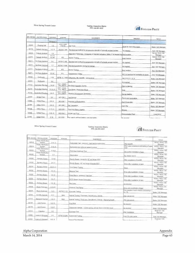
Alpha Corporation Appendix
March 14, 2014 Page 63
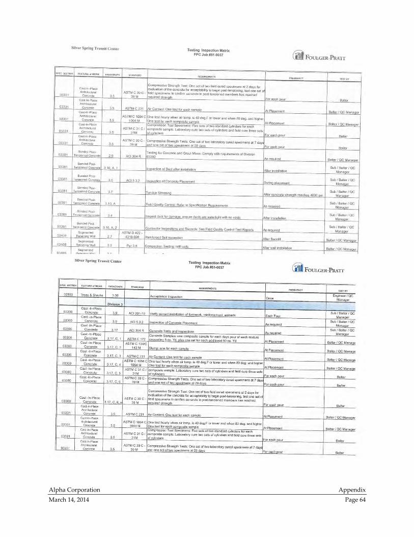
Alpha Corporation Appendix
March 14, 2014 Page 64
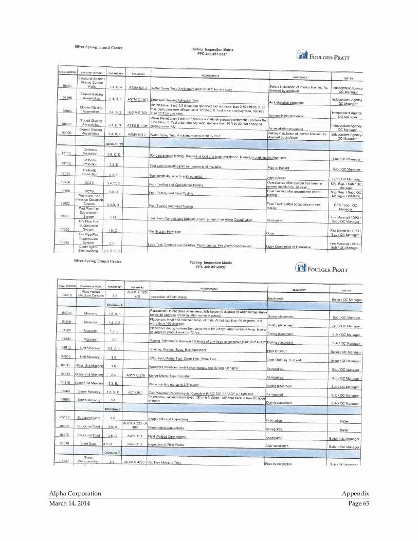
Alpha Corporation Appendix
March 14, 2014 Page 65
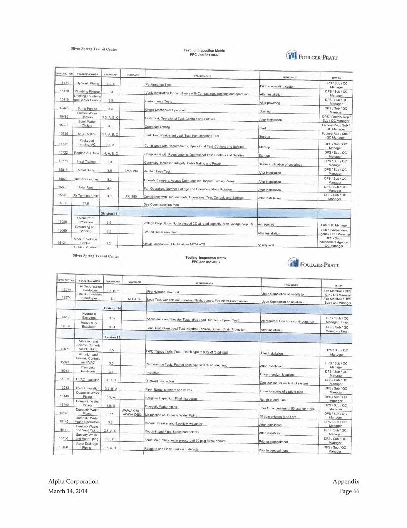
Alpha Corporation Appendix
March 14, 2014 Page 66
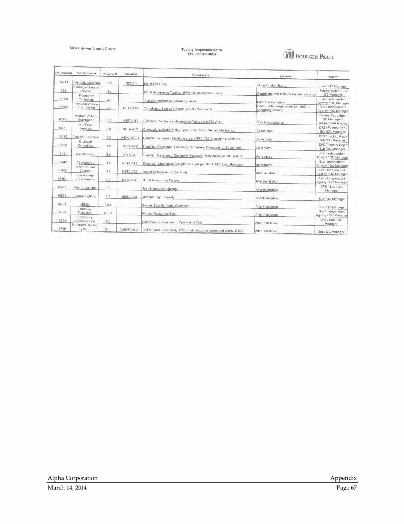
Alpha Corporation Appendix
March 14, 2014 Page 67

Alpha Corporation Appendix
March 14, 2014 Page 68
Appendix B – Duties and Functions of DGS
Project Management Team
Note: The information provided in this appendix was provided by DGS. It has been reformatted slightly
to fit this document but is otherwise not a product of this analysis. The descriptions provided have not
been verified and are provided for information purposes only.

Alpha Corporation Appendix
March 14, 2014 Page 69
Several County personnel are involved in the construction administration of the SSTC. The Montgomery
County Special Inspections Program outlines the duties and functions required by the owner or owner’s
representatives.155 The following outlines each individual’s duties and functions, which fulfill the
requirements.
The description of Mr. Anderson’s duties and functions as supplied by DGS include:
Works under the lead of the Project Manager Tim O’Gwin primarily to supports County with
interface with WMATA for All submittals – review and acceptance issues, coordination with PB
in the resolution of All submittal issues
As time evolved on the project this support grew to include coordination of the Safety & Security
Certification process (WMATA close out/checklist program), Commissioning and Closeout;
which are now his major activities since submittals are down to a minimum
Spends time in the site office and in the field to support the daily construction activities
Coordination with MTA with all QA/QC inspections and issues on the project
Support County activities in major settlement with the Contractor and their caisson sub‐
contractor to optimize DGS’s payment for extra caisson work on the project
Support DGS in other cost related (no time‐related) PCOs
Attends progress meetings, construction prep meetings, Commissioning meetings, Closeout
meetings, Safety & Security meetings, some MTA coordination meetings
Frank Roberts serves as Project Team Leader and his duties and functions include:
Performing all the functions of a Team Leader of the on‐site SSTC County personnel to manage
their day to day activities as well as reporting to the Division management on a day to day basis
Coordination with WMATA, MTA, FTA management of all project issues
Performing all the lead functions associated with managing the Prime Contract for both
Contractor and A/E, together with coordination and adherence to WMATA requirements as
defined in the MOU for the project. Additionally coordinates with MTA, FTA and DGS
management team to ensure that the work is proceeding according to agreements.
Coordinating with FP on‐site and home‐office management team including monthly MC/FP
management team meetings in which major problems are jointly flushed out ; works very closely
with PM on Field Orders and Change Orders with FP/PM to manage the fairness and accuracy of
that process
Spending time in the site office and in the field to support the daily construction activities
Coordinating with the PM on RFIs, ASIs and All project issues and problems to the level of detail
needed to get resolution and eliminate project delays
Assisting the PM with work associated with Review, negotiation and resolution of PCO by Field
Order or Change Order instrument
Attending all progress meetings, some construction prep meetings, project SWAT 3‐person team
meeting (FP/PB/County) PMP meetings (Chairs this meeting), FTA/MTA meetings, SSTC briefing
meetings, weekly team meetings, and prepares input to the respective meetings, and quarterly
MTA meeting as‐required
155 Montgomery County Special Inspections Program, Section 1.7.1 Owner (Owner’s Representatives), Page 4 of 26, Revised
10/26/2012
Alpha Corporation Appendix
March 14, 2014 Page 70
Keeping DGS Division management personnel well informed of all issues critical and pending
that will affect the success of the project, on a daily basis
Coordinating with Tim Herbold on daily urgent construction issues that need PM resolution
Monitoring the project website content and updates accordingly
Attending Safety & Security, Commissioning , Closeout meetings
Attending monthly schedule review meetings and reviews the schedules and Notices of Delay
proposed by the Contractor for input to County response and evaluation of those delay claims.
Tim O’Gwin serves as Project Manager and his duties and functions include:
Performing all the lead functions associated with managing the Prime Contract for both
Contractor and A/E, together with coordination and adherence to WMATA requirements as
defined in the MOU for the project. Additionally coordinating with MTA, FTA and DGS
management team to ensure that the work is proceeding according to agreements.
Spending time in the site office and in the field to support the daily construction activities
Reviewing, negotiating the Contractor’s PCOs for settlement (together with DGS’s cost
estimating contractor) and prepares all the documentation – Field Orders or Change Orders, for
settlement inclusive of meetings with the CRC (for Change Orders)
Reviewing all the contract RFIs & A/E responses for clarification for accuracy and agreement ; has
the final word in direction for closure of RFIs
Reviewing all the contract ASIs & A/E responses for clarification for accuracy and agreement ;
has the final word in direction for closure of RFIs
Attending all progress meetings, some construction prep meetings, PMP meetings, FTA/MTA
meetings, SSTC briefing meetings, weekly team meetings, and prepares input to the respective
meetings
Coordinating with Bob Stout in the running of the weekly A/E Design Team meetings
Coordinating monthly meetings with WMATA’s site construction personnel
Supporting the Project Team Leader in the resolution of All issues related to the execution of both
the A/E Contract and the Construction Contract
Acting as lead in the supervision of work done by PB’s on‐site construction management
engineer (John Anderson)
Coordinating with Tim Herbold on daily urgent construction issues that need PM resolution
Robert Stout serves as Assistant Project Manager and his duties and functions include:
Assisting the Project Manager ‐Tim O’Gwin and the Project Team Leader – Frank Roberts as‐
needed in the execution of all functions to support the management of the SSTC project; but
within those functions has some fixed roles such as All project Financial and Invoicing, and
Reports
Spending time in the site office and in the field to support the daily construction activities
Preparing All project Reports including monthly reports to MTA and FTA, and EOB Briefings
Coordinating the monthly PMP meetings that include the presence of
FTA/MTA/WMATA/PB/County and prepares minutes and agenda
Updating DGS input to the MTA Quarterly meetings on the project
Processing All the Invoices on the project – verification through payment, keeps an update on the
project financial balances
Administering PB Contract including assignment of task orders and ASIs
Assisting the PM in the review and execution of RFIs on the project so that DGS stays current and
in‐control of clarifications and potential changes
Alpha Corporation Appendix
March 14, 2014 Page 71
Coordinating and runs weekly meetings with the Design Team (PB/ZGF) and biweekly meetings
with MTA
Performing other duties as assigned by the PM and the Team Leader to assist with coordination
documentation with WMATA, FTA and MTA.
Leo Perez serves as County Scheduling Engineer and his duties and functions include:
Performing all the functions of an on‐site scheduling engineer including and not limited to daily
photos of All ongoing construction on the site in order to maintain records and to help to validate
the monthly schedule updates from the Contractor
Spending time in the site office and in the field to support the daily construction activities
Coordinating the monthly schedule reviews of the project which are attended by MTA and their
scheduling consultant, County and the Contractor
Assisting in preparation of letter responses to the contractor of schedule updates as well as
Notices of Delay
Assisting in review and preparation of DGS settlement with the Contractor for time lost in the
early phases of construction on the project – Change Order #8.
Attending all progress meetings, PMP meetings, some site prep meetings, schedule review
meetings and County biweekly management team meetings.
Supporting the activities of A/E in their review of project Notices of Delay from the Contractor;
TC26 schedule through the current TC42 schedule
Supporting the PM and Team Leader in numerous and miscellaneous activities involved with a
better understanding of construction slippage in time and issues that may be driving the
Contractor’s PCO submittal
Supporting the cost estimating efforts of the team as‐required
Tim Herbold serves as Senior Construction Representative and his duties and functions include:
overseeing the daily functions of Shakeel Bokhari
Spending majority of time on the site
Reporting daily construction activities, issues, problems, and look‐ahead conditions of the
construction activities to the Team Leader and Project Manager
Inspecting all site construction installations by General Contractor and Subcontractors including
but not limited to the major items of Earthwork, Sediment & Erosion Control, Caisson drilling &
concrete, Concrete, Steel, Post‐tensioning, Formwork, Finishes, Electrical & Mechanical
installations, Glazing , Escalator & Elevator installations, Paving, Underground & Above ground
Utility installations, Miscellaneous Metals installations
Coordinating and documents daily inspection performed by RBB in the execution of all the work
categories listed above; prepares daily Construction Representative reports for County use and
records
Reviewing RFIs, ASIs and other change instruments on the project and follows through
inspection with the Contractor on implementation of those Construction Documents
Attending construction preparatory meetings, biweekly progress meetings, superintendents’
meetings, subcontractor meetings, safety meetings, weekly SSTC project meetings,
Commissioning meetings, Closeout meetings, safety & Security meetings
Attending biweekly project Briefing meetings in the EOB and presents work status activities to
the SSTC management team
Reviewing RBB daily and monthly inspection reports
Reviewing and okays RBB’s monthly Invoices with corrections as‐needed
Alpha Corporation Appendix
March 14, 2014 Page 72
Reviewing the Contractor’s monthly Payment Applications, line by line, for accuracy and
inspects materials being billed for in the monthly Payment Applications
Maintaining a presence on the site during after –hours or weekend construction presence by the
General Contractor or their subs
Shakeel Bokhari serves as Construction Representative and his duties and functions include:
Reporting to the Senior Construction Representative, Tim Herbold for definition of daily
functions
Spending majority of time on the site
Inspecting all site construction installations by General Contractor and Subcontractors including
but not limited to the major items of Earthwork, Sediment & Erosion Control, Caisson drilling &
concrete, Concrete, Steel, Post‐tensioning, Formwork, Finishes, Electrical & Mechanical
installations, Glazing , Escalator & Elevator installations, Paving, Underground & Above ground
Utility installations, Miscellaneous Metals installations
Coordinating and documents daily inspection performed by RBB in the execution of all the work
categories listed above; prepares daily Construction Representative reports for County use and
records
Reviewing RFIs, ASIs and other change instruments on the project and follows through
inspection with the Contractor on implementation of those Construction Documents
Attending construction preparatory meetings, biweekly progress meetings, superintendents’
meetings, subcontractor meetings, safety meetings, weekly SSTC project meetings,
Commissioning meetings, Closeout meetings, safety & Security meetings
Reviewing RBB daily and monthly inspection reports
Reviewing the Contractor’s monthly Payment Applications, line by line, for accuracy and
inspects materials being billed for in the monthly Payment Applications
Maintaining a presence on the site during after –hours or weekend construction presence by the
General Contractor or their subs

Alpha Corporation Appendix
March 14, 2014 Page 73
Appendix C – Plans of SSTC Floors
Note: The information provided in this appendix is taken from KCE Attachments 11 and 26. It has been
reformatted slightly to fit this document but is not otherwise a product of this analysis. The content has
not been verified and is provided for information purposes only.

12/10/201011/12/2010
1/12/2011
9/13/201010/2/2010
12/30/20102/8/2011
10/18/201012/20/2010
4/19/2011
2/18/2011
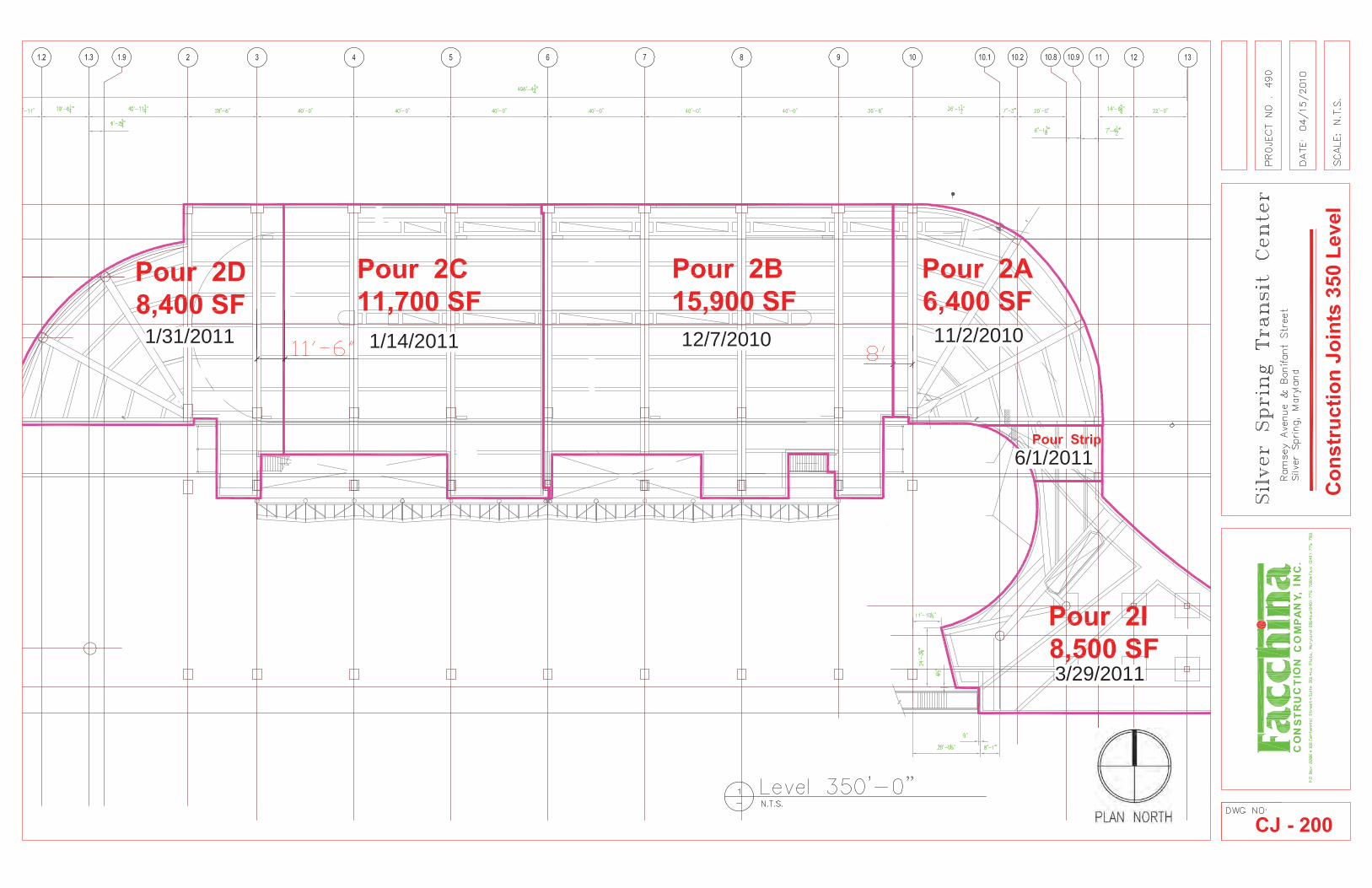
6/1/2011
3/29/2011
11/2/201012/7/20101/14/20111/31/2011
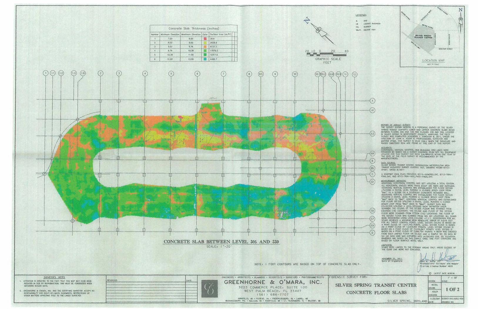
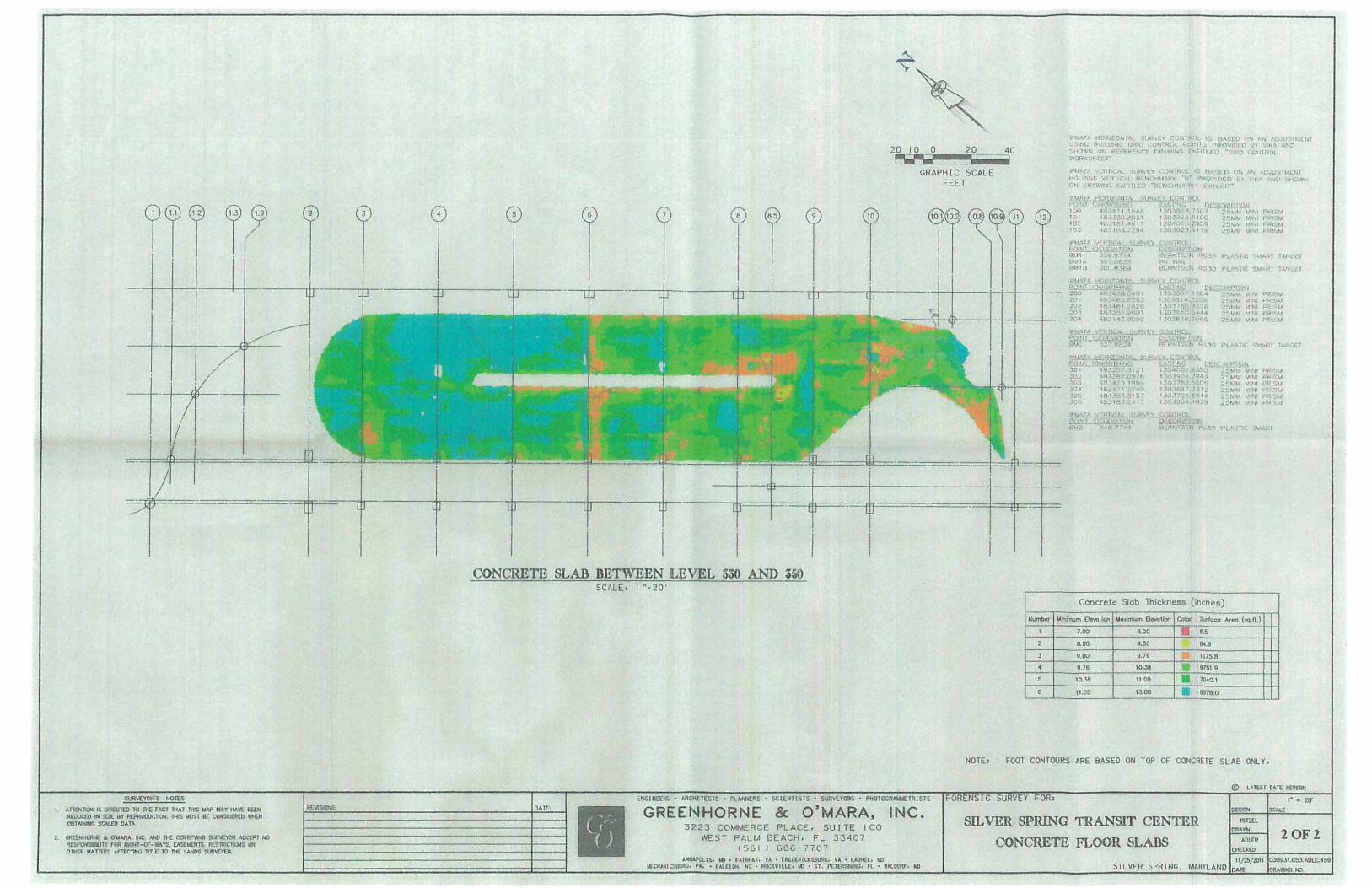
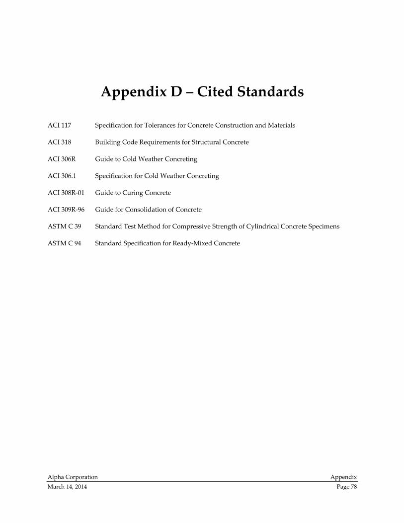
Alpha Corporation Appendix
March 14, 2014 Page 78
Appendix D – Cited Standards
ACI 117 Specification for Tolerances for Concrete Construction and Materials
ACI 318 Building Code Requirements for Structural Concrete
ACI 306R Guide to Cold Weather Concreting
ACI 306.1 Specification for Cold Weather Concreting
ACI 308R‐01 Guide to Curing Concrete
ACI 309R‐96 Guide for Consolidation of Concrete
ASTM C 39 Standard Test Method for Compressive Strength of Cylindrical Concrete Specimens
ASTM C 94 Standard Specification for Ready‐Mixed Concrete
Alpha Corporation Appendix
March 14, 2014 Page 79
Appendix E – Sample Reports
This appendix contains examples of some of the records that were reviewed during the analysis. It is not
intended to be complete, because several thousand pages of construction records were created for the
SSTC project. These sample pages are included for the benefit of the reader who does not have access to
the full KCE Exhibits. The samples selected for inclusion in this appendix are associated with concrete
pour 1Eb which was cast on December 10, 2010. This pour was chosen arbitrarily and illustrates cold
weather provisions.
Page Description KCE Exhibit Source
80 FP daily CQC report A4 pages 150, 151
82 RBB inspector’s daily report B4 pages 401, 403
84 concrete slab temperature report B4 page 405
86 concrete cylinder test specimen ticket S1 *
87 concrete cylinder test log S1 page 588
88 concrete cylinder break report R3 page 150
* The KCE Exhibit contains pages similar to the sample, but this particular page was missing
from the KCE Exhibit and was provided by RBB as page 187 of their April 22, 2013 letter.
Note: The information provided in this appendix is taken from the noted KCE Exhibits. It has been
reformatted slightly to fit this document but is not otherwise a product of this analysis. The content has
not been verified and is provided for information purposes only.
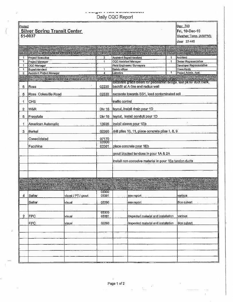
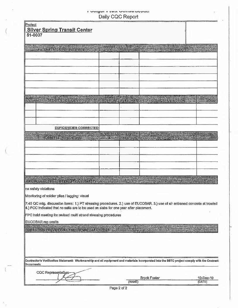
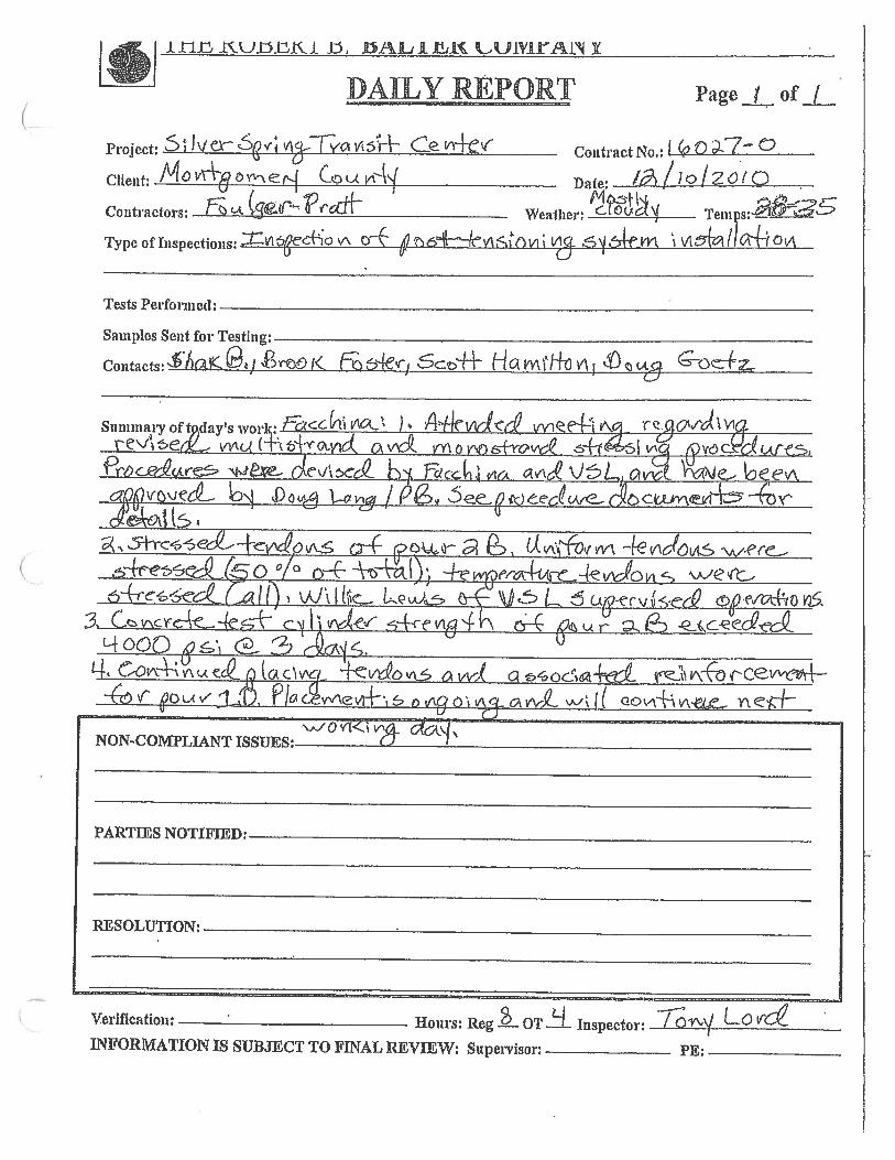
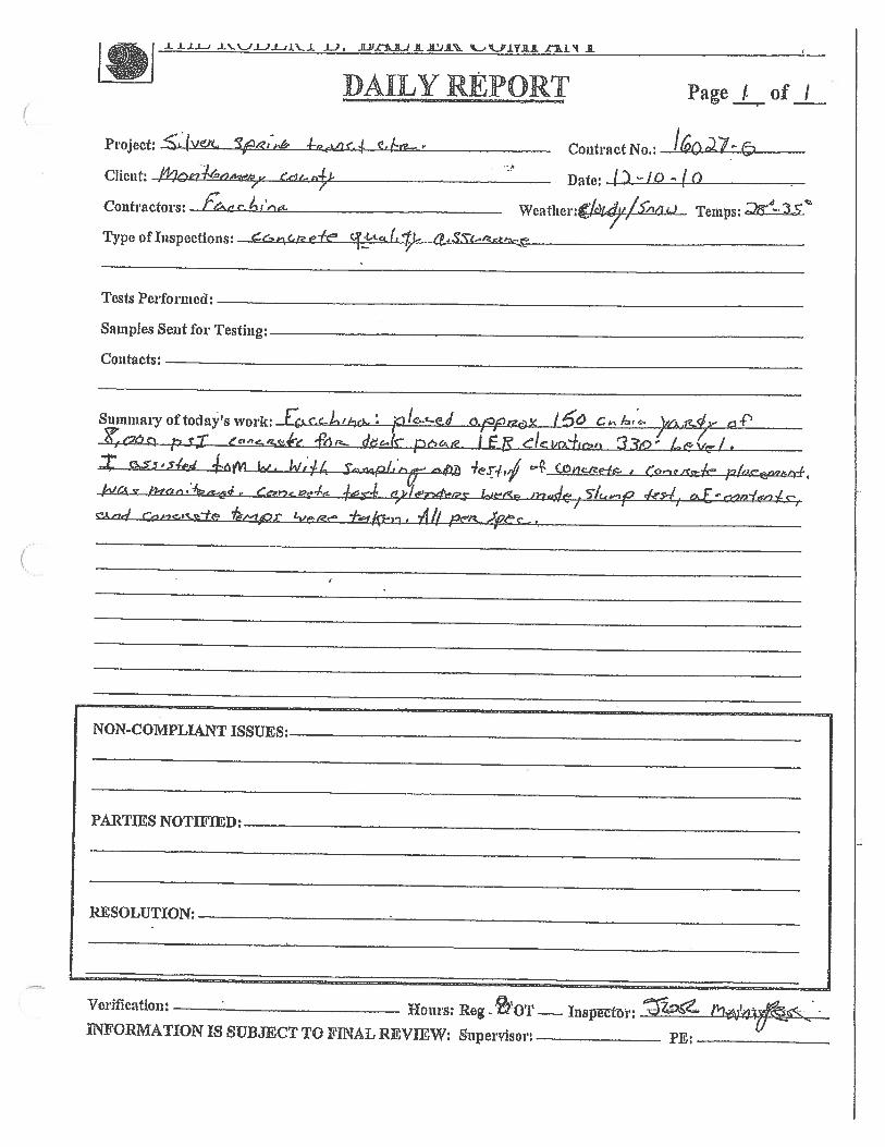
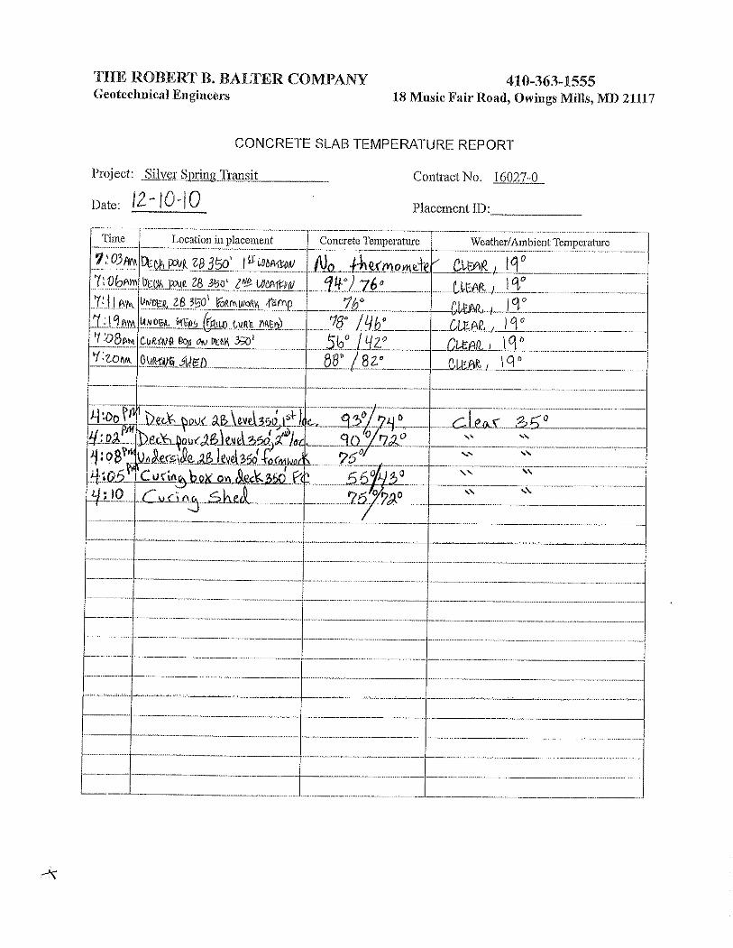
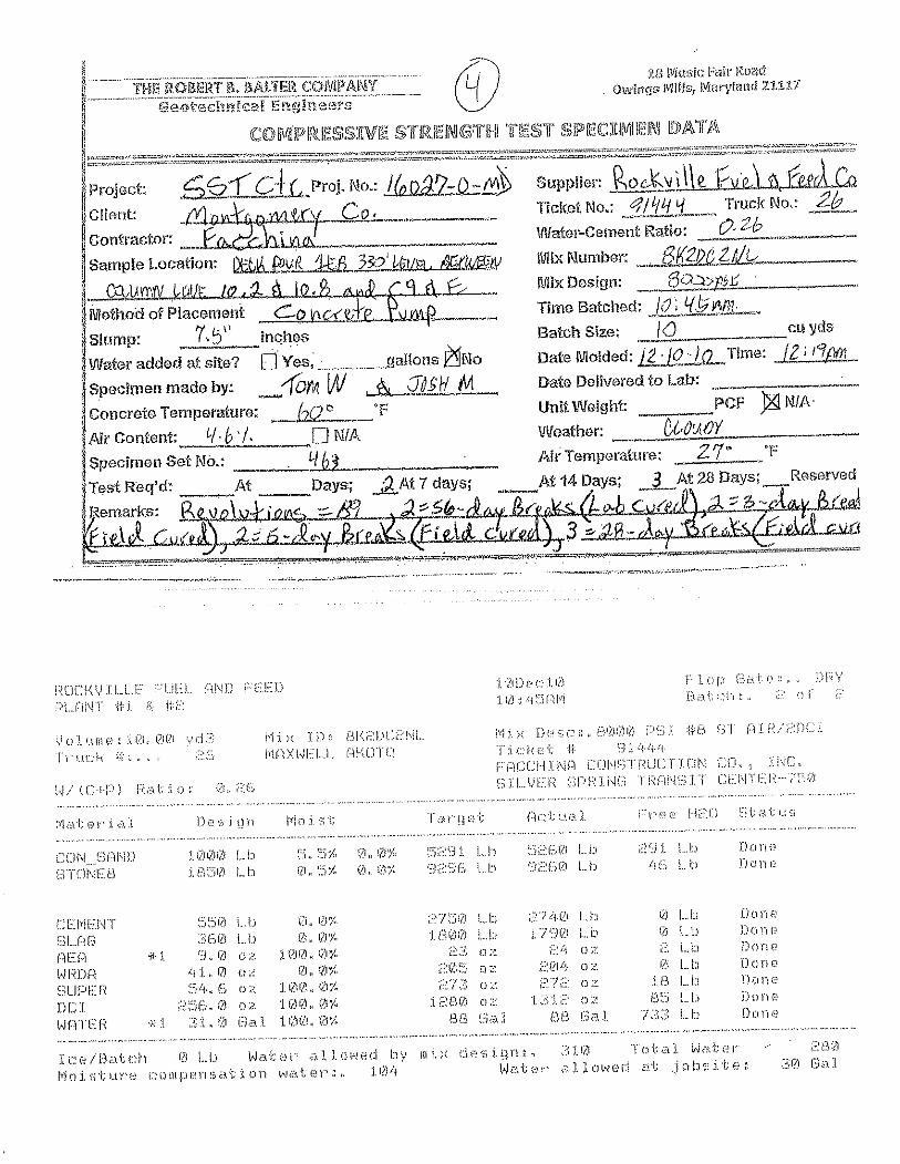
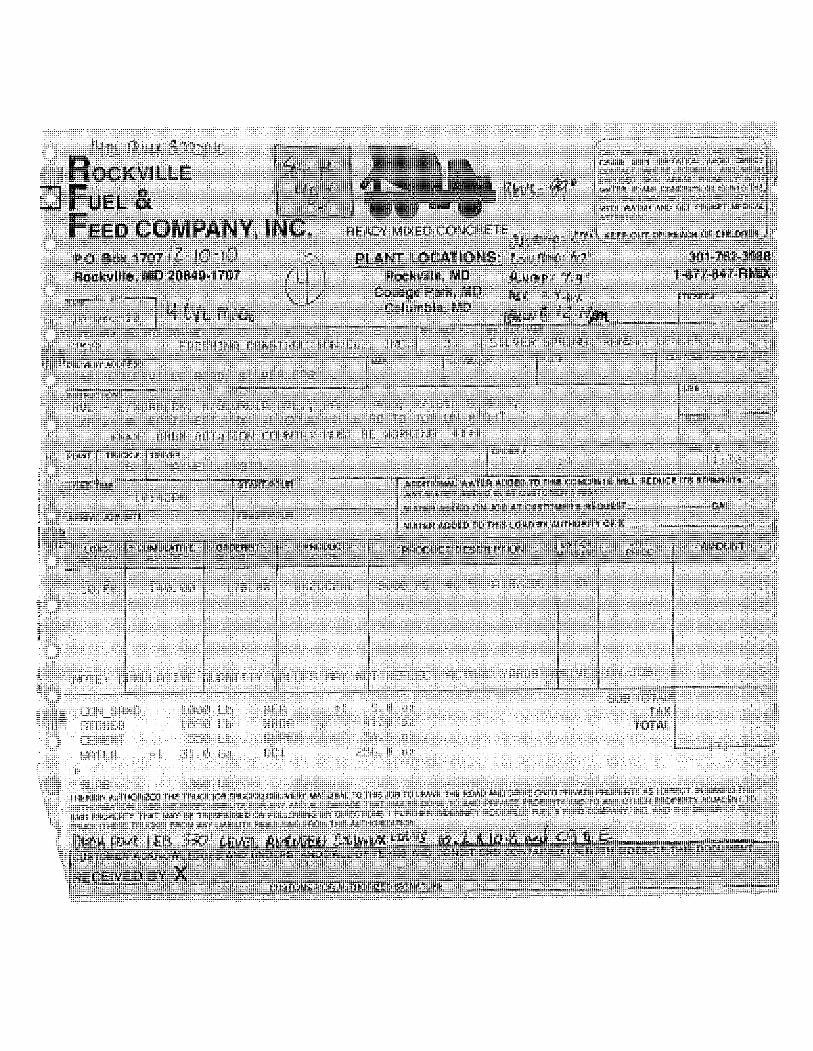
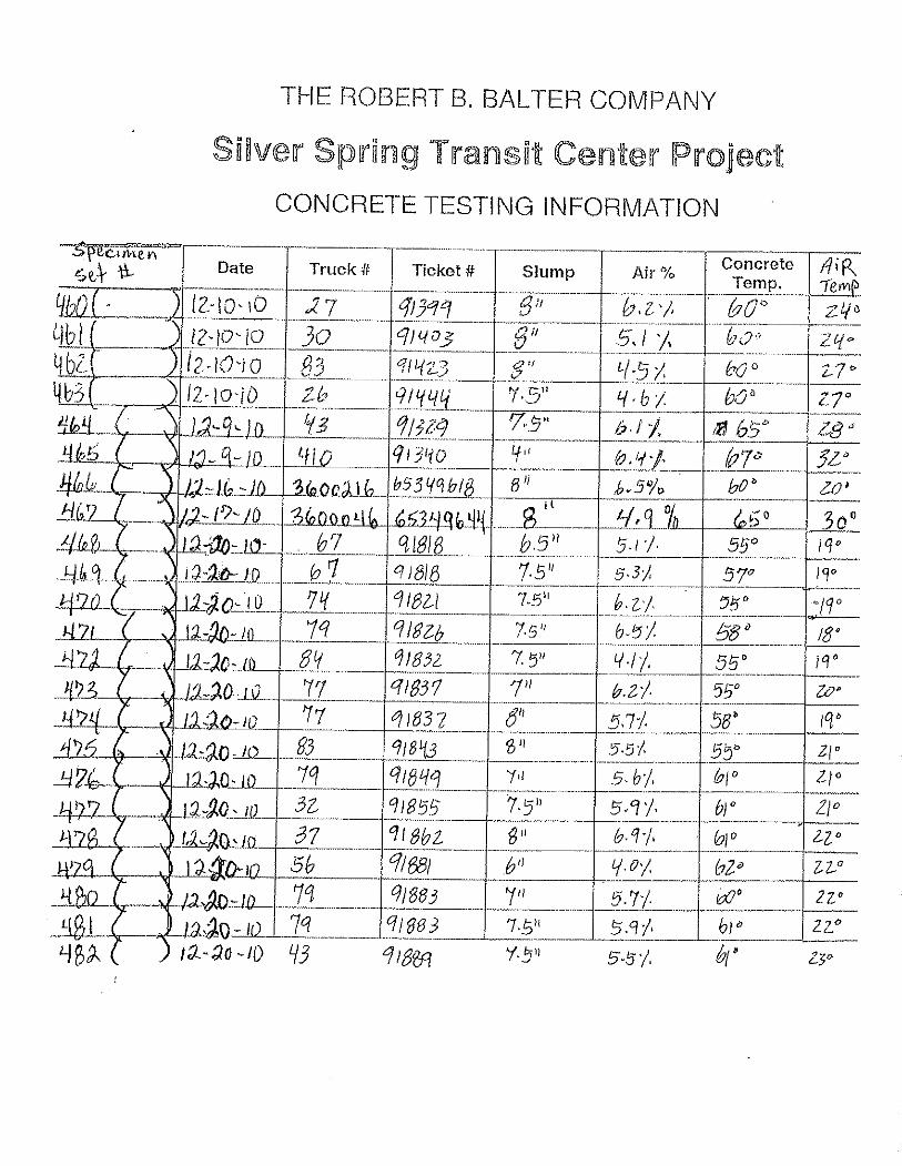
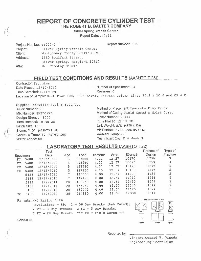

This Page Intentionally Blank

Alpha Corporation1800 Washington Boulevard, Suite 425
Baltimore, MD 21230Tel: (410) 646-3044 Fax: (410) 646-3730
www.alphacorporat ion.com