alt / vs selector / alerter pn 01279-( ) pilot’s...
TRANSCRIPT
SEL ALRALT DH VS BARO
ENT
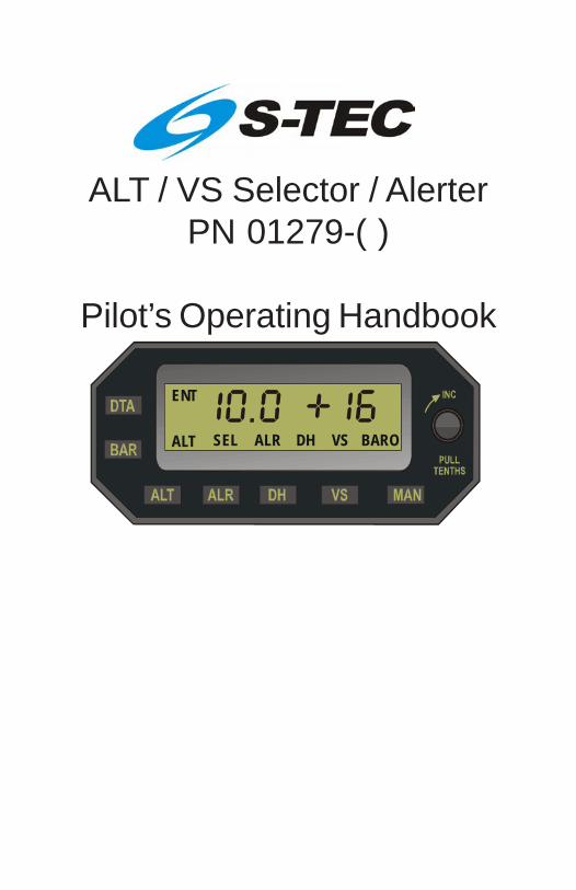
ALT / VS Selector / AlerterPN 01279-( )
Pilot’s Operating Handbook
3rd Ed. Jun 24, 16 i
S–TEC
List of Effective Pages * Asterisk indicates pages changed, added, or deleted by current revision.
Record of Revisions Retain this record in front of handbook. Upon receipt of a revision, insert changes and complete table below.
Revision Number Revision Date Insertion Date/Initials 1st Ed. Oct 26, 00
2nd Ed. Jan 15, 08
3rd Ed. Jun 24, 16

ii 3rd Ed. Jun 24, 16
S–TEC
Page Intentionally Blank

3rd Ed. Jun 24, 16 iii
S–TEC
Table of ContentsSec. Pg.
1 Overview...........................................................................................................1–1
1.1 Document Organization....................................................................1–3
1.2 Purpose..............................................................................................1–3
1.3 General Control Theory....................................................................1–3
1.4 Block Diagram....................................................................................1–4
2 Pre-Flight Procedures...................................................................................2–1
2.1 Pre-Flight Test....................................................................................2–3
3 In-Flight Procedures......................................................................................3–1
3.1 Selector / Alerter Operation..............................................................3–3
3.1.1 Data Entry.............................................................................3–3
3.1.2 Barometric (BARO) Calibration.......................................3–3
3.1.3 Altitude (ALT) Select...........................................................3–4
3.1.4 Vertical Speed (VS) Select.................................................3–5
3.1.5 Decision Height (DH) Select............................................3–7
3.1.6 Altitude Alerter (ALR) Function..........................................3–8
3.1.7 Loss of Encoded Altitude..................................................3–8
3.1.8 Selector / Alerter Disconnect............................................3–9
3.2 Autopilot Operation............................................................................3–10
4 Operating Parameters..................................................................................4–1
4.1 Ranges.................................................................................................4–3
5 Glossary...........................................................................................................5–1

iv 3rd Ed. Jun 24, 16
S–TEC
List of FiguresFig. Pg.
1–1 ALT / VS Selector / Alerter Block Diagram...................................................1–5
2–1 Selector / Alerter Display, All Segments and Annunciations Appear.......2–4
2–2 Selector / Alerter Display, Enter Barometric Correction............................2–4
3–1 Selector / Alerter Display, Loss of Encoded Altitude..................................3–9
List of TablesTable Pg.
2–1 Pre-Flight Test...............................................................................................2–3

3rd Ed. Jun 24, 16 1-1
S–TEC
SECTION 1OVERVIEW

1-2 3rd Ed. Jun 24, 16
S–TEC
Page Intentionally Blank

3rd Ed. Jun 24, 16 1-3
S–TEC
1.1 Document Organization
Section 1 Overview
Section 2 Pre-Flight Procedures
Section 3 In-Flight Procedures
Section 4 Operating Parameters
Section 5 Glossary
1.2 Purpose
This Pilot's Operating Handbook (POH) provides Pre-Flight and In-Flightoperating procedures for the S-TEC Altitude (ALT) / Vertical Speed (VS) Selector/ Alerter.
Note:
This POH must be carried in the A/C and made available to the pilot atall times. It can only be used in conjunction with the Federal AviationAdministration (FAA) approved Aircraft Flight Manual (AFM) or Aircraft FlightManual Supplement (AFMS). Refer to the applicable AFM or AFMS forA/C specific information, such as unique ground tests, limitations, andemergency procedures.
Note:
The Selector / Alerter is a tool provided to aircraft owners, that serves toassist them with cockpit workload management. The ability of theSelector / Alerter to provide optimum assistance and performance isdirectly proportional to the pilot's knowledge of its operating procedures.Therefore, it is highly recommended that the pilot develop a thoroughunderstanding of the Selector / Alerter and its operating procedures inVisual Meteorological Conditions (VMC), prior to using it under InstrumentFlight Rules (IFR).
1.3 General Control Theory
The Selector / Alerter can be used with the following S-TEC autopilots:
System Fifty Five X
System Sixty Two
System Sixty Five
Pitch Stabilization System (PSS)
HeliSAS (with 01311-04-XXX FCC's only)
1-4 3rd Ed. Jun 24, 16
S–TEC
The Encoding Altimeter / Blind Encoder sends the encoded altitude to theSelector / Alerter. The encoded altitude must be converted to the true altitude,through barometric calibration.
The selected altitude and selected vertical speed must be programmed into theSelector / Alerter. Thereafter, upon engaging the autopilot's vertical speed modeand arming its altitude hold mode, the aircraft will attain and hold the selectedvertical speed. As the aircraft approaches the selected altitude, a scheduledreduction in the selected vertical speed will automatically occur. This enablesthe aircraft to transition from vertical flight to altitude capture, without adverseacceleration. Once the selected altitude has been captured, the autopilot'svertical speed mode will disengage and its altitude hold mode will engage. Theaircraft will then hold the selected altitude.
1.4 Block Diagram
The Selector / Alerter Block Diagram is shown in Fig. 1-1.

3rd Ed. Jun 24, 16 1-5
S–TEC
Fig. 1-1. ALT / VS Selector / Alerter Block Diagram
0 12
34
567
89ALT.
ENCODED
MAX.RANGE20,000
100 FEET
SEL ALRALT DH VS BARO
ENT
DECR
INCR
HDG NAV APR REV TRIM ALT GS VSRD
Y
CW
S
FA
IL
GPS
S
VS x 100
F F XIFTY IVE
VS SELECTALT ENGAGE
ENCODEDALTITUDE
ENCODING ALTIMETER / BLIND ENCODER
TDR
I 2 0 0ON ALTSBYOFF TST
DIMREPLYIDENT
AUTOPILOT
TRANSPONDER
SELECTOR / ALERTER

1-6 3rd Ed. Jun 24, 16
S–TEC
Page Intentionally Blank

3rd Ed. Jun 24, 16 2-1
S–TEC
SECTION 2PRE-FLIGHT PROCEDURES

2-2 3rd Ed. Jun 24, 16
S–TEC
Page Intentionally Blank

3rd Ed. Jun 24, 16 2-3
S–TEC
ACTION RESPONSE 1. Set Battery Master Switch to ON position.
------
2. Set Avionics Master Switch to ON position.
------
3. Set Transponder Master Switch to ON position.
------
4. Set Encoding Altimeter / Blind Encoder Master Switch to ON position.
------
5. Set Autopilot Master Switch to ON position.
------
6. Complete Autopilot Pre-Flight Procedures contained in respective POH.
------
7. Set ALT Alerter Master Switch to ON position.
A two-tone audible alert sounds once.
All left numeric segments, all right polarity / numeric segments, and all annunciations (ENT, ALT, SEL, ALR, DH, VS, BARO) appear on Selector / Alerter display for 5 seconds, as shown in Fig. 2-1.
Thereafter, only ENT annunciation
and left numeral 29.9 (barometric pressure in inches mercury) appear, along with a flashing BARO annunciation, as shown in Fig. 2-2.
2.1 Pre-Flight Test
Prior to takeoff and with engine running, perform the actions shown in Table 2-1.For each action, verify the corresponding response where applicable.
Table 2-1. Pre-Flight Test (continued on page 2-4)

2-4 3rd Ed. Jun 24, 16
S–TEC
Fig. 2-1. Selector / Alerter Display, All Segments and Annunciations Appear
Fig. 2-2. Selector / Alerter Display, Enter Barometric Correction

3rd Ed. Jun 24, 16 2-5
S–TEC
ACTION RESPONSE 8. Set Altimeter to posted airport elevation.
------
9. Rotate Selector / Alerter Modifier Knob as required, until barometric pressure (inches of mercury) on display matches that shown on Kollsman scale of Altimeter.
------
Note:
To convert barometric pressure to millibars, press Selector / Alerter BAR switch once.
10. Press Selector / Alerter ALT switch.
------
11. Rotate Selector / Alerter Modifier Knob as required, until altitude on left numeric field of display is 400 feet above airport elevation.
------
12. Press Selector / Alerter VS switch.
------
13. Rotate Selector / Alerter Modifier Knob as required, until vertical speed polarity on right numeric field of display is positive (+).
------
14. Press Selector / Alerter DTA switch.
------
15. Set Heading Bug on DG or HSI under Lubber Line.
------
Note:
This does not apply to HeliSAS and may not apply to the System Sixty PSS.
Table 2-1. Pre-Flight Test (continued from page 2-3)
2-6 3rd Ed. Jun 24, 16
S–TEC
ACTION RESPONSE
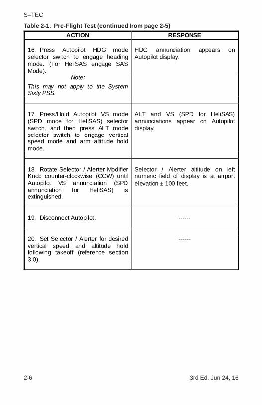
16. Press Autopilot HDG mode selector switch to engage heading mode. (For HeliSAS engage SAS Mode).
HDG annunciation appears on Autopilot display.
Note: This may not apply to the System Sixty PSS.
17. Press/Hold Autopilot VS mode (SPD mode for HeliSAS) selector switch, and then press ALT mode selector switch to engage vertical speed mode and arm altitude hold mode.
ALT and VS (SPD for HeliSAS) annunciations appear on Autopilot display.
18. Rotate Selector / Alerter Modifier Knob counter-clockwise (CCW) until Autopilot VS annunciation (SPD annunciation for HeliSAS) is extinguished.
Selector / Alerter altitude on left numeric field of display is at airport elevation ± 100 feet.
19. Disconnect Autopilot. ------
20. Set Selector / Alerter for desired vertical speed and altitude hold following takeoff (reference section 3.0).
------
Table 2-1. Pre-Flight Test (continued from page 2-5)

3rd Ed. Jun 24, 16 3-1
S–TEC
SECTION 3IN-FLIGHT PROCEDURES

3-2 3rd Ed. Jun 24, 16
S–TEC
Page Intentionally Blank

3rd Ed. Jun 24, 16 3-3
S–TEC
3.1 Selector / Alerter Operation
3.1.1 Data Entry
Press the DTA switch, such that ENT is annunciated. Any of the followingquantities can now be entered into the Selector / Alerter:
Barometric Calibration (reference section 3.1.2)
Selected Altitude (reference section 3.1.3)
Selected Decision Height (reference section 3.1.5)
Whenever ENT is annunciated, the Selector / Alerter is decoupled from theautopilot. In that case, if the Selector / Alerter happens to have vertical speedcommand authority as indicated on its display, then the autopilot will hold theaircraft at the last selected vertical speed.
Once the particular quantity has been entered, press the DTA switch again tomake it operational. The ENT annunciation will extinguish as a result.
Note:
It is not necessary for ENT to be annunciated, in order to enter vertical speedselection changes.
3.1.2 Barometric (BARO) Calibration
The true altitude is the altitude above Mean Sea Level (MSL). The output of anEncoding Altimeter / Blind Encoder is the altitude expressed as a digital GrayCode, relative to the standard barometric pressure of 29.9 inches of mercury(inHg) or 1013 millibars (mb). This output is known as the encoded altitude.
When the Altimeter is set to the true altitude, the barometric pressure at MSL willbe shown on its Kollsman scale. The Selector / Alerter must then be calibratedto the Altimeter. This is accomplished by changing the barometric pressuresetting on the Selector / Alerter to match the Kollsman scale. As a result, theencoded altitude at the input of the Selector / Alerter is internally converted to thetrue altitude, for use in making computations.
Following the power-up self test (reference section 2.0), the barometricpressure setting is 29.9 inHg, and ready to be changed to match the Kollsmanscale. Rotate the Modifier Knob clockwise (CW) to increase the barometricpressure setting, or counter-clockwise (CCW) to decrease the setting. Eachdetent changes the setting by 0.1 inHg, regardless of whether the Modifier Knobis pushed-in or pulled-out.
The units of barometric pressure can be changed from inHg to mb, by pressingthe BAR switch. Each CW or CCW detent of the Modifier Knob changes thebarometric pressure setting by 1 mb, regardless of whether the Modifier Knob ispushed-in or pulled-out. When the setting is greater than 999 mb, theone-thousand digit is not shown. For example, a setting of 1013 mb wouldappear only as 013. The units of barometric pressure can be changed back toinHg, by pressing the BAR switch again.

3-4 3rd Ed. Jun 24, 16
S–TEC
Once the barometric pressure setting has been entered, press the DTA switch tomake it operational, such that the ENT annunciation is extinguished and theBARO annunciation stops flashing.
To change the barometric setting at times other than immediately followingpower-up, press the DTA switch such that ENT is annunciated. Then press theBAR switch, such that the BARO annunciation appears flashing. The setting canthen be changed using the Modifier Knob as described above. Once thebarometric pressure setting has been entered, press the DTA switch again tomake it operational, such that the ENT annunciation is extinguished and theBARO annunciation stops flashing.
The Selector / Alerter barometric pressure setting will automatically change to29.9 inHg or 1013 mb, above an altitude of 18,000 feet (FL 180). Even so, thelast setting will continue to appear unchanged. Prior to descending belowFL 180, change the barometric pressure setting as required for the new area.Once subsequently at or below FL 180, the Selector / Alerter will automaticallyreference this setting.
3.1.3 Altitude (ALT) Select
Press the DTA switch (more than once if necessary, depending on the currentconfiguration of the Selector / Alerter), such that ENT and ALT are both annunciated,and the SEL annunciation is flashing. The selected altitude is now ready to beentered. Rotate the Modifier Knob clockwise (CW) to increase the altitudeselection, or counter-clockwise (CCW) to decrease the selection. When theModifier Knob is pushed-in, each detent changes the selection by 1000 FT.When the Modifier Knob is pulled-out, each detent changes the selection by100 FT.
Once the selected altitude has been entered, press the DTA switch to make itoperational, such that the ENT annunciation is extinguished and the SELannunciation stops flashing.
To display the true altitude, press the ALT switch. The SEL annunciation willextinguish as a result. To go back and display the selected altitude, press theALT switch again. The SEL annunciation will re-appear as a result.
If the newly selected vertical speed is not compatible with the selected altitude,then the latter will flash for 5 seconds to alert the pilot accordingly. There will beno automatic change to the selected altitude.
Suppose that the aircraft is at an initial altitude of 5,000 FT, with a selectedvertical speed of 100 FPM climbing and a selected altitude of 6,000 FT. If theselected vertical speed is subsequently changed to 100 FPM descending, thenthe selected altitude (6.0 on display) will flash for 5 seconds.
Suppose that the aircraft is at an initial altitude of 6,000 FT, with a selectedvertical speed of 100 FPM descending and a selected altitude of 5,000 FT. If theselected vertical speed is subsequently changed to 100 FPM climbing, then theselected altitude (5.0 on display) will flash for 5 seconds.

3rd Ed. Jun 24, 16 3-5
S–TEC
3.1.4 Vertical Speed (VS) Select
Press the VS switch. The VS annunciation will appear, along with the selectedvertical speed. The latter appears as a number in units of FPM x 100, prefixed byeither a "+" to indicate a climb, or a "-" to indicate a descent (i.e., for example,+5 indicates 500 FPM climbing). For a climb, rotate the Modifier Knob clockwise(CW) to increase the vertical speed selection, or counter-clockwise (CCW) todecrease the selection. For a descent, rotate the Modifier Knob CCW toincrease the vertical speed selection, or CW to decrease the selection.
It is not necessary for ENT to be annunciated, in order to enter the selectedvertical speed and for it to be operational. If ENT does happen to be annunciated,then the VS annunciation will flash when the VS switch is pressed. In that case,pressing the DTA switch will cause the ENT annunciation to extinguish, the VSannunciation to stop flashing, and the selected vertical speed to becomeoperational.
The Selector / Alerter now has vertical speed command authority. The ability tocommand vertical speed from the autopilot controls is disabled.
Note:
HeliSAS does not have the ability to command vertical speed.
These controls for each respective autopilot are as follows:
System Fifty Five X - Modifier Knob
System Sixty Two - UP Switch and DN Switch
System Sixty Five - UP Switch and DN Switch
Pitch Stabilization System (PSS) - UP Switch and DN Switch
The acknowledgment that its commanded vertical speed is coming from theSelector / Alerter is as follows, for each respective autopilot:
System Fifty Five X - SEL annunciation appears on optional Remote Annunciator
- Current Vertical Speed extinguished (polarity and number)
System Sixty Two - SEL annunciation appears on Programmer/Annunciator
System Sixty Five - SEL annunciation appears on Annunciator
Pitch Stabilization System (PSS) - No Acknowledgment
HeliSAS - Not applicable

3-6 3rd Ed. Jun 24, 16
S–TEC
To revert vertical speed command authority back to the autopilot controls, pressthe MAN switch.
Note:
This function is not applicable to HeliSAS.
This will be acknowledged by the Selector / Alerter, through the extinguishment ofits VS annunciation and selected vertical speed.
During a climb or descent, a scheduled reduction in the selected vertical speedwill automatically occur as the aircraft approaches the selected altitude. Thisenables the aircraft to transition from vertical flight to altitude capture, withoutadverse acceleration.
The selected vertical speed will decrease in increments, as the aircraft arrivesat fixed displacement points from the selected altitude. The result is that thevertical speed will be 300 FPM at altitude capture, which occurs 100 FT from theselected altitude.
ppose that the aircraft is at an initial altitude of 10,000 FT, with a selected verticalspeed of 1600 FPM climbing and a selected altitude of 11,100 FT. The sched-uled reduction in vertical speed will be as follows:
Altitude (FT) Vertical Speed (FPM)10,000 160010,100 140010,200 110010,300 100010,400 90010,500 80010,600 70010,700 60010,800 50010,900 40011,000 300
Suppose that the aircraft is at an initial altitude of 11,100 FT, with a selectedvertical speed of 1600 FPM descending and a selected altitude of 10,000 FT.The scheduled reduction in vertical speed will be as follows:
Altitude (FT) Vertical Speed (FPM)11,100 160011,000 140010,900 110010,800 100010,700 90010,600 80010,500 70010,400 60010,300 50010,200 40010,100 300
3rd Ed. Jun 24, 16 3-7
S–TEC
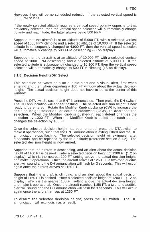
However, there will be no scheduled reduction if the selected vertical speed is300 FPM or less.
If the newly selected altitude requires a vertical speed polarity opposite to thatpreviously selected, then the vertical speed selection will automatically changepolarity and magnitude, the latter always being 500 FPM.
Suppose that the aircraft is at an altitude of 5,000 FT, with a selected verticalspeed of 1000 FPM climbing and a selected altitude of 10,000 FT. If the selectedaltitude is subsequently changed to 4,900 FT, then the vertical speed selectionwill automatically change to 500 FPM descending (-5 on display).
Suppose that the aircraft is at an altitude of 10,000 FT, with a selected verticalspeed of 1000 FPM descending and a selected altitude of 5,000 FT. If theselected altitude is subsequently changed to 10,100 FT, then the vertical speedselection will automatically change to 500 FPM climbing (+5 on display).
3.1.5 Decision Height (DH) Select
This selection activates both an audible alert and a visual alert, first whenentering and then when departing a 100 FT window about the actual decisionheight. The actual decision height does not have to be at the center of thiswindow.
Press the DTA switch, such that ENT is annunciated. Then press the DH switch.The DH annunciation will appear flashing. The selected decision height is nowready to be entered. Rotate the Modifier Knob clockwise (CW) to increase thedecision height selection, or counter-clockwise (CCW) to decrease theselection. When the Modifier Knob is pushed-in, each detent changes theselection by 1000 FT. When the Modifier Knob is pulled-out, each detentchanges the selection by 100 FT.
Once the selected decision height has been entered, press the DTA switch tomake it operational, such that the ENT annunciation is extinguished and the DHannunciation stops flashing. The selected decision height will extinguish after5 seconds, and be replaced by the true altitude (reference section 3.1.2). Theselected decision height is now armed.
Suppose that the aircraft is descending, and an alert about the actual decisionheight of 1160 FT is desired. Enter a selected decision height of 1200 FT (1.2 ondisplay), which is the nearest 100 FT setting above the actual decision height,and make it operational. Once the aircraft arrives at 1250 FT, a two-tone audiblealert will sound and the DH annunciation will flash for 3 seconds. This will occuragain once the aircraft arrives at 1150 FT.
Suppose that the aircraft is climbing, and an alert about the actual decisionheight of 1160 FT is desired. Enter a selected decision height of 1200 FT (1.2 ondisplay), which is the nearest 100 FT setting above the actual decision height,and make it operational. Once the aircraft reaches 1150 FT, a two-tone audiblealert will sound and the DH annunciation will flash for 3 seconds. This will occuragain once the aircraft arrives at 1250 FT.
To disarm the selected decision height, press the DH switch. The DHannunciation will extinguish as a result.

3-8 3rd Ed. Jun 24, 16
S–TEC
3.1.6 Altitude Alerter (ALR) Function
This function activates both an audible alert and a visual alert, at fixeddisplacement points from the selected altitude.
Enter the selected altitude, and make it operational (reference section 3.1.3).Press the ALR switch to arm the altitude alerter function. The ALR annunciationwill appear as a result. Thereafter, once the aircraft arrives at 1000 FT from theselected altitude, a two-tone audible alert will sound and the ALR annunciationwill flash for 3 seconds. This will occur again, once the aircraft arrives at 300 FTfrom the selected altitude.
Following capture of the selected altitude, should the aircraft ever happen todeviate from it by 300 FT, there will again occur the two-tone audible alert andflashing ALR annunciation.
To disarm the altitude alerter function, press the ALR switch. The ALRannunciation will extinguish as a result.
3.1.7 Loss of Encoded Altitude
Should the encoded altitude at the input of the Selector / Alerter ever be lost(i.e., interrupted), then a two-tone audible alert will sound 3 times, while thedisplayed altitude is replaced by flashing dashes as shown in Fig. 3-1.Thereafter, these dashes stop flashing but remain.
In that event, the selected altitude is no longer attainable using the Selector /Alerter. In addition, if the Selector / Alerter happens to have vertical speedcommand authority as indicated on its display, then immediately press the MANswitch to revert such authority back to the autopilot.
Note:
This function is not applicable to HeliSAS.

3rd Ed. Jun 24, 16 3-9
S–TEC
Fig. 3-1. Selector / Alerter Display, Loss of Encoded Altitude
3.1.8 Selector / Alerter Disconnect
If a Selector / Alerter malfunction is suspected, then set the ALT Alerter MasterSwitch to the OFF position. Do not attempt further use of the Selector / Alerter,until it has been inspected by authorized service personnel. A Selector / Alertermalfunction will not likely cause an autopilot failure.
Should the encoded altitude be subsequently restored, then the dashes will bereplaced by the displayed altitude. The Selector / Alerter can then be re-programmedfor use.
3-10 3rd Ed. Jun 24, 16
S–TEC
3.2 Autopilot Operation
Program the Selector / Alerter for the selected vertical speed and selectedaltitude. On the autopilot, press/hold the VS mode (SPD mode for HeliSAS)selector switch and then press the ALT mode selector switch, to engage thevertical speed mode and arm the altitude hold mode. The VS and ALTannunciations will appear on the autopilot display. The aircraft will attainand hold the selected vertical speed.
As the aircraft approaches the selected altitude, a scheduled reduction in theselected vertical speed will automatically occur. This enables the aircraft tocapture the selected altitude, without adverse acceleration. Once the selectedaltitude has been captured, the VS annunciation (SPD annunciation for HeliSAS) onthe autopilot display will extinguish, to indicate engagement of the altitudehold mode. The aircraft will hold the selected altitude.
Note:
With the vertical speed mode engaged and the altitude hold mode armed:
1. Pressing the ALT mode selector switch on the autopilot will engage thealtitude hold mode, and disengage the vertical speed mode. Consequently,the VS annunciation (SPD annunciation for HeliSAS) will extinguish on theautopilot display. This may cause some adverse acceleration, as the autopilotworks to hold the aircraft at the captured altitude.
2. Pressing the VS mode (SPD mode for HeliSAS) selector switch on theautopilot will disarm the altitude hold mode, but leave the vertical speedmode (indicated airspeed mode for HeliSAS) engaged. Consequently, theALT annunciation will extinguish on the autopilot.

3rd Ed. Jun 24, 16 4-1
S–TEC
SECTION 4OPERATING PARAMETERS

4-2 3rd Ed. Jun 24, 16
S–TEC
Page Intentionally Blank

3rd Ed. Jun 24, 16 4-3
S–TEC
4.1 Ranges
Altitude (ALT) Select Range
0.0 to 35.9 Thousand FT
Altitude Alerter (ALR) Function Range
0.0 to 35.9 Thousand FT
Barometric (BARO) Calibration Range
27.9 to 32.0 inHg
945 to 1083 mb
Decision Height (DH) Select Range
0.0 to 35.9 Thousand FT
Vertical Speed (VS) Select Range
Selector / Alerter PN 01279-PX: 1600 FPM Climbing or Descending
Selector / Alerter PN 01279-PM: 3000 FPM Climbing or Descending

4-4 3rd Ed. Jun 24, 16
S–TEC
Page Intentionally Blank

3rd Ed. Jun 24, 16 5-1
S–TEC
SECTION 5GLOSSARY

5-2 3rd Ed. Jun 24, 16
S–TEC
Page Intentionally Blank
3rd Ed. Jun 24, 16 5-3
S–TEC
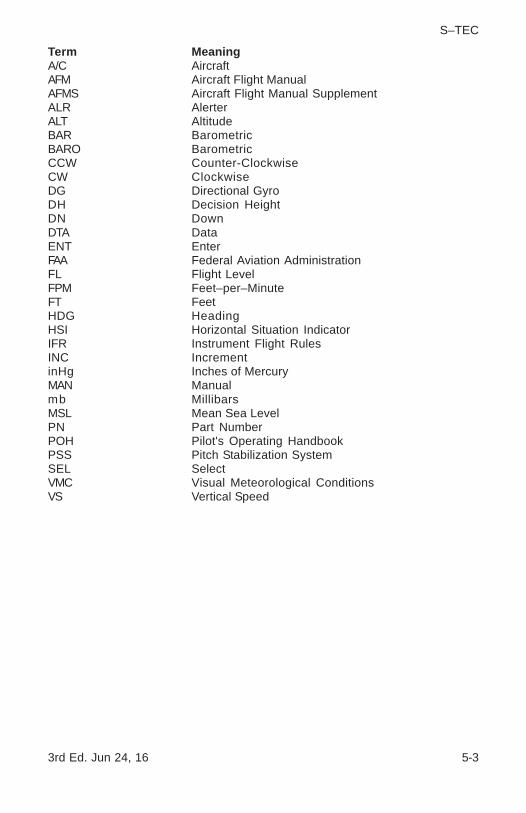
Term MeaningA/C AircraftAFM Aircraft Flight ManualAFMS Aircraft Flight Manual SupplementALR AlerterALT AltitudeBAR BarometricBARO BarometricCCW Counter-ClockwiseCW ClockwiseDG Directional GyroDH Decision HeightDN DownDTA DataENT EnterFAA Federal Aviation AdministrationFL Flight LevelFPM Feet–per–MinuteFT FeetHDG HeadingHSI Horizontal Situation IndicatorIFR Instrument Flight RulesINC IncrementinHg Inches of MercuryMAN Manualmb MillibarsMSL Mean Sea LevelPN Part NumberPOH Pilot's Operating HandbookPSS Pitch Stabilization SystemSEL SelectVMC Visual Meteorological ConditionsVS Vertical Speed

5-4 3rd Ed. Jun 24, 16
S–TEC
Page Intentionally Blank

One S–TEC WayMunicipal Airport
Mineral Wells, TX 76067–9236 Tel: 800–872–7832Fax: 940–325–3904
www.genesys-aerosystems.comS–TEC PN 87110
Information contained in this document is subject to changewithout notice. © 2016 S-TEC. All rights reserved. Printed inthe United States of America. S-TEC and the S-TEC logoare registered trademarks of S-TEC.
Notice:Contact S-TEC Customer Support at 800-872-7832 for aService Repair Order (SRO) number prior to the return of anycomponent for any reason.