alternative approach to teach gas turbine based power cycles · alternative approach to teach gas...
TRANSCRIPT

Paper ID #12859
Alternative approach to teach gas turbine based power cycles
Dr. Farshid Zabihian, West Virginia University Inst. of Tech.
Farshid Zabihian, Ph.D. Assistant Professor Department of Mechanical Engineering West Virginia Uni-versity Institute of Technology
Education: Ph.D., Mechanical Engineering,Ryerson University, 2011 M.S. Mechanical Engineering, IranUniversity of Science and Technology, 1998 B.S. Mechanical Engineering, Amir Kabir University ofTechnology, 1996
Authored or coauthored more than 70 papers in Journals and peer-reviewed conferences.
c©American Society for Engineering Education, 2015

ALTERNATIVE APPROACH TO TEACH GAS TURBINE BASED POWER
CYCLES
Farshid Zabihian
West Virginia University Institute of Technology
Montgomery, West Virginia, U.S.A
ABSTRACT
This paper presents the new approach in teaching Applied Thermodynamics in general and gas
turbine cycles in particular to undergraduate mechanical engineering students through the
integration of a simulation and modeling software to teaching gas turbine based cycles.
Students developed several simple models and conducted sensitivity analysis and interpreted the
results through modeling. First, they are asked to find various properties of a stream using the
software and compare them with the values they found from the conventional thermodynamic
tables. In this step students learn how to retrieve stream properties and how to validate them.
Then, they develop a cycle composed of a compressor followed by a gas turbine. In this stage,
they learn how to define characteristics and specifications of components in the model. Also, they
experience the influences of these specifications on the performance of the equipments. As a next
step, they add a combustion chamber to the model to make a complete model of a sample gas
turbine cycle. As a part of this step they calculate the net output power, specific work, and
efficiency of the cycle. They utilize this model to evaluate effects of the compressor pressure
ratio, turbine inlet temperature, ambient temperature and pressure, efficiency of compressor and
turbine, and pressure drop in the combustion chamber on the system overall performance
parameters including output power, specific work, and efficiency of the cycle. Eventually, some
students worked on this model and combined it with other cycles to make a hybrid cycle or other
cycles as their projects.
INTRODUCTION
When the author started to teach Thermodynamics, he realized that the teaching methods for
thermodynamics have not been changed much since he took the course himself about 20 years
ago. So he started to look for other resources and teaching methods. He reviewed and evaluated
25 thermodynamics textbooks covering 1963 - 2013 [1-25]. Great majority of them are using the
same teaching approach. Only two of them are taking advantages of computational tools [9, 11].
Three relatively new techniques in teaching are as follows:
2
CONCEPTUAL-BASED LEARNING VS. CALCULATION-BASED LEARNING
The responsibilities of engineers are usually designing systems. In majority of cases, the design
process involves some sort of calculation. That is why traditionally engineering education heavily
emphasized the calculation techniques. Until 90s this approach was reasonable and perfectly
fitted the requirements of industry. But in the past couple of decades, the applications of
computational tools have made a major shift in the industry. Engineers no longer do complicated
calculation manually. They just need to design configuration of systems, identify and input data
to software, and more importantly analysis and validate the results. This process requires
conceptual understanding of topics, skills in using the software, and analysing the results.
For example, when teaching steam cycles, students do not need to be taught how to do the
calculation for open and closed feed-water heater, reheater, superheater, economizer, etc. They
only need to learn simple steam cycle calculation and how each of these components affects the
performance of the cycle. Then, they need to know how to develop the models to simulate these
cycles and evaluate the effects of various parameters.
SYSTEM LEVEL VS. PROCESS LEVEL LEARNING
Traditionally teaching thermodynamics starts with definition of terminology followed by how to
find thermodynamics properties e.g. property tables, ideal gas calculation, and property relation
for fluid and solid. Then, the concept of heat and work are introduced followed by conservation
laws, including the conservation of mass and the first and second laws of thermodynamics. These
laws are all presented for processes rather than systems.
When the foundation of thermodynamics laid out, these fundamentals are applied in the system
level to teach thermodynamics cycles.
In the system level learning, these concepts are presented in the reverse order.
TRADITIONAL TEACHING VS. PROBLEM/PROJECT-BASED TEACHING
In traditional teaching, first a concept is presented and then examples, problems, and projects
based on the presented topic are presented. In the problem/project based teaching, first a
problem/project is introduced and then the skills needed to solve the problem are developed.
INTEGRATION OF PROCESS MODELING SOFTWARE TO APPLIED
THERMODYNAMICS
The combination of three aforementioned methods, namely conceptual learning, system level
learning, and problem/project-based teaching has led the teaching approach presented in this
paper. A commercial process modeling software is utilized to deepen student understanding of
the gas turbine-based cycles and evaluation of effects of various parameters on the cycle
performance. In this course, Aspen Plus is used for this purpose.
3
FIRST ASSIGNMENT
Students are first introduced to the software and learn how to work with it through several step
by step tutorials.
SECOND ASSIGNMENT
The objective of this assignment is to teach students how to extract thermodynamics parameters
from the software. Also, students are asked to find same properties from their textbook and
compare them with what they found from the software. They realize that the values of some
parameters, such as density, are the same regardless of the source of information i.e. their
textbook or the software. But for some properties, such as enthalpy and entropy, they find totally
different values. At this point, I ask them to compare the values of the enthalpy and entropy
difference between two states found from the tables and the software. The students can see
firsthand that the differences are the same because the two methods are just using different
reference points to report the properties.
THIRD ASSIGNMENT
The objective of this assignment is to investigate the effects of pressure and temperature of
various thermodynamics parameters of the streams. They develop two simple models. One model
includes a simple pressure change device e.g. half-closed valve. The temperature of the flow is
constant and only the pressure changes. Students are supposed to find the effects of pressure on
the specific volume, enthalpy, and entropy at constant pressure and draw the diagrams of these
properties as a function of pressure. The different student teams will be assigned with various
substances e.g. water, ammonia, carbon dioxide, etc.
The other model will include a simple heat exchanger with no pressure drop. The students will
perform the same analysis but for independent variable of temperature at constant pressure. They
also validate their results using the tables from the textbook.
FOURTH ASSIGNMENT
At this point, the students are ready to integrate various components in their modeling. In this
assignment, I ask students to develop an Aspen Plus® model for a compressor followed by a
turbine with the following specifications. They are supposed to run their model and report the
results for the following three cases with different inlet flows to the compressor and two sets of
efficiencies for the turbine and the compressor.
The objective of this assignment is to investigate the effects of equipment characteristics on the
performance of the system. They also recognize the significant impact of the efficiencies of the
turbine and the compressor on the overall performance system.

4
In order to improve their communication skills, I ask them to prepare a technical report for each
assignment. The report should be prepared based on the technical report preparation guideline
that I give them and should include:
A table showing all main information of all streams for each case,
A table showing all main information of turbine and compressor,
The net work and efficiency of each system,
A comparison of the results for cases 1 and 2,
Discussion on the results.
Compressor:
Type: Isentropic
Pressure ratio (P2/P1): 10
Isentropic efficiency: 80% and 90%
Mechanical efficiency: 75% and 85%
Turbine:
Type: Isentropic
Pressure ratio (P1/P2): 10
Isentropic efficiency: 80% and 90%
Mechanical efficiency: 75% and 85%
Three cases for compressor inlet:
Case 1:
Stream composition (mass fraction): air 100%
Temperature: 40°C
Pressure: 1 atm (absolute)
Mass flow rate: 100 kg/s
Case 2:
Stream composition (mass fraction): N2 79%, O2 21%
Temperature: 40°C
Pressure: 1 atm (absolute)
Mass flow rate: 100 kg/s
Case 3:
Stream composition (mass fraction): water 100%
Temperature: 400°C
Pressure: 10 atm (absolute)
Mass flow rate: 100 kg/s
For Properties/Property methods and models the students use following information:
Process type: POWER
Base method: PR-BM
5
FIFTH ASSIGNMENT
This assignment is similar to the previous one but in this one a chemical reaction i.e. combustion
is added to the cycle. This is the first time that the students develop the model of an actual
system.
In this assignment, the students are asked to develop an Aspen Plus® model for a simple gas
turbine cycle consists of a compressor followed by a combustion chamber and a gas turbine with
the following specifications. They are supposed to run their model and report the results for the
following two cases with different inlet fuels. The report should be a professional one and should
include:
A table showing all main information of all streams for each case,
A table showing all main information of the equipment,
LHV and HHV of the fuel for each case,
Efficiency (based on LHV and HHV) and net work production of the cycle,
A comparison of the results for cases 1 and 2,
A comparison of the results for case 2 with the operational values from the Whitby
cogeneration power plant at the same conditions: Output power 58 MW, GT exhaust
temperature 431°C (find the errors and explain any possible sources for the errors),
Discussion on the results.
Compressor:
Type: Isentropic
Pressure ratio (P2/P1): 33.7
Isentropic efficiency: 80% and 90%
Mechanical efficiency: 75% and 85%
Turbine:
Type: Isentropic
Pressure ratio (P1/P2): 32.1
Isentropic efficiency: 80% and 90%
Mechanical efficiency: 75% and 85%
Two cases for the inlet fuel:
Case 1:
Fuel pure methane
Case 2:
Fuel with following composition:
Air inlet stream:
Temperature: 10°C

6
Pressure: 100.232 kPa (absolute)
Mass flow rate: 158.2 kg/s
Stream composition (mass fraction): N2 79%, O2 21%
Fuel inlet stream:
Temperature: 68°C
Pressure: 55.5atm (absolute)
Mass flow rate: 10,793 kg/h
Stream composition (mass fraction): case 1 and case 2.
As stated, the students should compare the results of their model with the performance data of an
actual cycle from the Whitby cogeneration power plant. They also report on the sources of the
discrepancy between modeling results and actual data. As a part of this step they calculate the net
output power, specific work, and efficiency of the cycle. They utilize this model to evaluate
effects of the compressor pressure ratio, turbine inlet temperature, ambient temperature and
pressure, efficiency of compressor and turbine, and pressure drop in the combustion chamber on
the system overall performance parameters including output power, specific work, and efficiency
of the cycle.
PROJECTS
The assignment five is the last uniform assignment for whole class. Beyond this point the
students should form a team and choose a project from the following list. They may also suggest
their own topic for the project.
Modeling of a gas turbine-based cogeneration cycle: exergy analysis.
Modeling of a combine cycle power plant (CCPP): exergy analysis.
Modeling of a gas turbine-based cogeneration cycle: effect of the compressor inlet air cooling
system.
Modeling of a combine cycle power plant (CCPP): effect of the compressor inlet air cooling
system.
Experimental and numerical analyses of the micro gas turbine.
Modeling of ocean thermal energy convertors (OTEC).
Modeling of geothermal systems.
Modeling of an Organic Rankine Cycle (ORC).
Modeling of a gas turbine cycle: exergy analysis.
Modeling of hybrid tubular solid oxide fuel cell (SOFC) and gas turbine cycle
Modeling of an Integrated Gasification Combined Cycle (IGCC).
Modeling of air separation units.
Modeling of CO2 capture units.
Modeling of Oxyfuel power plants.
SAMPLE PROJECT
7
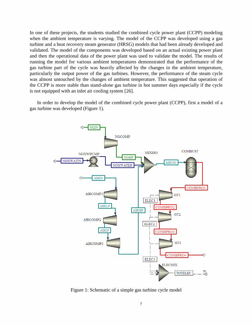
In one of these projects, the students studied the combined cycle power plant (CCPP) modeling
when the ambient temperature is varying. The model of the CCPP was developed using a gas
turbine and a heat recovery steam generator (HRSG) models that had been already developed and
validated. The model of the components was developed based on an actual existing power plant
and then the operational data of the power plant was used to validate the model. The results of
running the model for various ambient temperatures demonstrated that the performance of the
gas turbine part of the cycle was heavily affected by the changes in the ambient temperature,
particularly the output power of the gas turbines. However, the performance of the steam cycle
was almost untouched by the changes of ambient temperature. This suggested that operation of
the CCPP is more stable than stand-alone gas turbine in hot summer days especially if the cycle
is not equipped with an inlet air cooling system [26].
In order to develop the model of the combined cycle power plant (CCPP), first a model of a
gas turbine was developed (Figure 1).
Figure 1: Schematic of a simple gas turbine cycle model

8
This model then was validated against the data collected from operation of the actual gas turbine
system. This model and its validation along with the important thermodynamic properties and
operational parameters have been presented elsewhere [27, 28].
The next step was to add a heat recovery steam generator (HRSG) to the bottom of the cycle and
again validate the model. The results of this step were presented elsewhere [27].
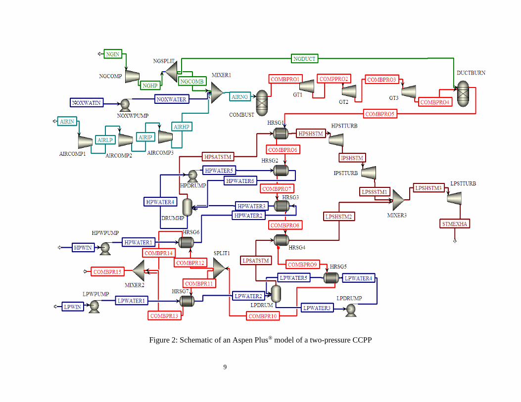
The final step was to develop the complete model of the CCPP. Figure 2 illustrates the model of
the CCPP cycle developed for this project. The model was run with the ambient temperature
range from 5 degrees Celsius to 45 degrees Celsius, with 5 degree increments. Table 1 shows the
power produced by the gas turbines and steam turbines along with the power consumed by air
and natural gas compressors.
9
Figure 2: Schematic of an Aspen Plus® model of a two-pressure CCPP

10
Table 1: Power produced by the gas turbines, steam turbines, and entire system along with power
consumed by air and natural gas compressors at each temperature
Ambient
Temp.
(◦C)
Power Output
of Gas Turbines
(MW)
Power Output of
Steam Turbines
(MW)
Power Consumption of
Compressors (MW)
Net Total Power
Production (MW)
5 163.38 20.77 100.62 83.53
10 160.23 20.77 100.52 80.48
15 157.19 20.77 100.41 77.55
20 154.26 20.77 100.31 74.72
25 151.42 20.77 100.20 71.99
30 148.69 20.77 100.10 69.35
35 146.04 20.77 99.99 66.81
40 143.48 20.77 99.89 64.36
45 141.00 20.77 99.78 61.99
DISCUSSION
This alternative approach to teaching gas turbine based power engines to undergraduate students
seem to be effective and engaging.
In this course, I also use active learning method. In this teaching methodology, unlike traditional
methods, students are not just passive listeners. Before each session, students are assigned a
section of the textbook. They must read the assigned section and come to class prepared. In the
beginning of each class, there is a quiz related to the assigned reading. Then, there is discussion
on the questions in the quiz. During this discussion, the concept related to the topic(s) of the day
is reviewed. Depending on the topic, there may be a numerical problem(s) that is attempted by
the students and instructor. Finally, the class is concluded by a quiz related to the material
covered in the class.
REFERENCES
[1] M.W. Zemansky, H.C. Van Ness, 1966, Basic Engineering Thermodynamics, McGraw-Hill,
New York.
[2] Jefferson W. Tester, Michael Modell, 1997 Thermodynamics and Its Applications (3rd
Edition), Prentice hall, New Jersey.
[3] Jesse S. Doolittle, Francis J. Hale, 1983,
Thermodynamics for Engineers, John wiley& Sons.
[4] Dwight C., Jr. Look, Harry J. Sauer, Jr., 1982,
Thermodynamics, Brooks/Cole Engineering Division, CA.
[5] Joseph H. Keenan, Frederick G. Keyes, 1936,

11
Thermodynamic properties of steam, John wiley& Sons Inc. New York.
[6] Ashley H. Carter, 2001, Classical and statistical Thermodynamics, Prentice Hall, New Jersey.
[7] Kurt C. Rolle, 2005, Thermodynamics and Heat Power (6th edition), Pearson- Prentice Hall,
New Jersey.
[8] Yunus A. Cengel, Michael A. Boles, 1998, Thermodynamics An Engineering Approach 3rd
ed., McGraw-Hill., Boston.
[9] Yunus A. Cengel, Michael A. Boles, 2008, Thermodynamics An Engineering Approach 7th
ed., McGraw-Hill., New York.
[10] Glen E. Myers, Engineering Thermodynamics, Prentice Hall, 1989, Englewood Cliffs, N.J.
[11] Renaud Gicquel, 2012, Energy Systems: A New Approach to Engineering Thermodynamics
CRC Press.
[12] Robert F. Boehm, 1987, Design Analysis of Thermal Systems, John Wiley & Sons, New
York.
[13] Adrian Bejan, George Tsatsaronis, Michael Moran, 1996, Thermal Design and Optimization,
John Wiley & Sons, Inc., New York.
[14] Claus Borgnakke, Richard E. Sonntag, 2009, Fundamentals of Thermodynamics, 7th ed.,
John Wiley & Sons, Inc.
[15] Gordon J. Van Wylen, Richard E. Sonntag, 1986, Fundamentals of Classical
Thermodynamics, 3rd ed., John Wiley & Sons, Inc., New York.
[16] Michael J. Moran, Howard N. Shapiro, Daisie D. Boettner, Margaret B. Bailey, 2011,
Fundamentals of Engineering Thermodynamics 7th ed., Wiley & Sons, Inc.
[17] Stephen R. Turns, 2006, Thermodynamics: Concepts and Applications, Cambridge
University Press, Hong Kong.
[18] Kaufui Vincent Wong, 2000, Thermodynamics for Engineers, 2nd Edition, CRC Press, New
York.
[19] William Z. Black, James G. Hartley, 1985, Thermodynamics, Harper & Row Publisher, New
York.
[20] Kam W. Li, 1996, Applied Thermodynamics: Availability Method And Energy Conversion,
CRC Press, London.
[21] Joachim E Lay, 1963, Thermodynamics, a macroscopic-microscopic treatment, Charles E.
Merrill Books, Inc. Columbus, OH.
[22] Merle Potter, 1996, Engineering Thermodynamics, McGraw-Hill, New York.
[23] Yunus A. Cengel, 2008, Introduction to Thermodynamics and heat Transfer, McGraw-Hill,
Boston.
[24] Allan D. Kraus, James R. Welty, Abdul Aziz, 2012, Introduction to Thermal and Fluid
Engineering, CRC Press, Roca Raton, FL.

12
[25] Kalyan Annamalai, Ishwar K. Puri, Milind A. Jog, 2011, Advanced Thermodynamics
Engineering 2nd ed., CRC Press, Roca Raton, FL.
[26] Shaw, Paul J.; Zabihian, Farshid; Fung, Alan, “Gas Turbine-Based Combined Cycle Power
Plant Modeling and Effects of Ambient Temperature”, ASME 7th International Conference on
Energy Sustainability, July 2013, Minneapolis, Minnesota, U.S.A.
[27] Zabihian F., Fung A., Schuler F., 2012, “Modeling of Gas Turbine-Based Cogeneration
System,” ASME 6th International Conference on Energy Sustainability and ASME 2012 10th
Fuel Cell Science, Engineering and Technology Conference, 2012, San Diego, California, USA.
[28] Zabihian F., Fung A., Schuler F., 2012, “Performance Evaluation of Evaporative Compressor
Inlet Air Cooling System in a Gas Turbine-Based Cogeneration Plant,” ASME 2012 Power
Conference, 2012, Anaheim, California, USA.