alternative of infrastructure gis marine vessel under the ...ceur-ws.org/vol-2522/paper19.pdf ·...
TRANSCRIPT

203
Alternative of Infrastructure GIS Marine Vessel Under
the Purpose of Swimming*
Tatiana M. Tatarnikova1[0000-0002-6419-0072] and Natalia Yagotinceva1
1 Russian State Hydrometeorological University, 79, Voronelsraya st., 192007 St. Pe-
tersburg, Russia
Abstract. Designing a geographic information control system for a marine vessel
is a complex systematic process, characterized by a combined application stage
of automatic generation the structure of geographic information system and ex-
pert solutions. The purpose of the research is to develop methodological support
for the formation of a geographic information system by successively approxi-
mating its structural-functional model to a given set of properties. It has been
proposed a structural-functional model of a geographic information system for
controlling a marine vessel. Quantitative and qualitative description of the model
allows performing structural optimization of the geographic information system
for different purposes. It has been developed a methodology for forming the
structure of a geographic information system for controlling a marine vessel. It
has been developed as an expert system, which automates this methodology. The
expert system allows in the interactive mode to form a list of the necessary equip-
ment and functional modules of the geographic information system. The practical
significance of the results presented in the article lies in the fact that the expert
system can be useful in the design of integrated control systems for marine dy-
namic objects.
Keywords: dynamic object, geographic information system, decision making,
management of a dynamic object, structural-functional model, method of form-
ing the infrastructure of a dynamic object, sea vessel, local network.
1 Introduction
The use of geographic information systems (GIS) in the management of dynamic ob-
jects is a complex task that requires the use of special mathematical models, methodol-
ogies and software and hardware tools for the implementation of GIS [1]. Especially
this task becomes actual to the management of marine vessels. It is necessary to obtain
real-time information about their location, environment, meteorological conditions cal-
* Copyright 2019 for this paper by its authors. Use permitted under Creative Commons License
Attribution 4.0 International (CC BY 4.0).
204
culate the route load, time of arrival and, based on this data, make decisions about lay-
ing and adjusting the route [2].
Analysis of publications and regulatory documents of the last 5-7 years in the tech-
nical implementation of the tasks of managing marine vessels has shown that this field
is developing in the direction of integrating existing complexes, stations, systems, and
functional elements into a geographic information system of a marine vessel, which
built on the technology of local switching networks.
On the other hand, the implementation of a GIS for the control of a sea vessel is
associated with a number of problems.
These problems include:
─ the need to operate with large volumes of heterogeneous geographic data coming
from different sources and often in incompatible formats [3];
─ limited area of the vessel for the implementation of infrastructure GIS on it [4];
─ lack of an integrated approach for designing such GIS with regard to the existing
limitations on its performance and reliability [5].
2 Structural and functional model of GIS marine vessel
The structural-functional model of the GIS of control a marine vessel can be rep-re-
sented as a three-layer structure. The inner layer corresponds to the information support,
medium – software and external – hardware [3, 4].
GIS information support is the cartographic data and data necessary for controlling
the vessel. Together, these data form an electronic cartographic navigation in-formation
system.
The software implements the functionality of GIS and consists of basic software and
application software. The basic software consists of operating systems, database man-
agement systems, data visualization systems, and others. Application software designed
to solve specialized problems of navigation, signal processing, data processing, and
transmission and others.
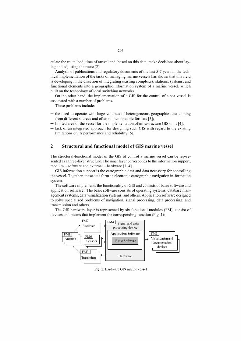
The GIS hardware layer is represented by six functional modules (FM), consist of
devices and means that implement the corresponding function (Fig. 1):
Receiver
FM2 Signal and data
processing device
Hardware
FM4
Application Software
Basic SoftwareAntenna
FM1
FM3
Transmitter
FM5
Visualization and
documentation
devices
Sensors
FM6
Fig. 1. Hardware GIS marine vessel

205
FM1: devices that convert electromagnetic (acoustic) energy, as in the case of radiation,
and as receiving signals, or in other words, antennas.
FM2: devices that receive, amplify, demodulate and decode signals, or in other
words, receivers.
FM3: devices performing reception, amplification, modulation and transmission of
signals, or in other words, transmitters.
FM4: means of processing received signals and data.
FM5: visualization tools that provide a dynamic display of marine vessels and their
trajectories; documentation of data on the card and paper carrier; document viewing
and statistical display of the most important data.
FM6: devices that transform the effects of the environment into electromagnetic sig-
nals, or in other words, sensors.
A local computer network with segment switching is the transport of GIS marine
vessels. This technology allows us to simultaneously transferring data between all in-
teracting pairs of "Client-Server" (Fig. 2) [6].
...
FM4: Servers
Data
processing
Data
Base
FM1-FM3, FM6:
Antennas, transceivers
and sensors
...
Signal
processing
Switching
...
Fax
machinesPrinters
Streamers Plotters
Circle view
indicators
FM5: Visualization and
documentation devicesСlients
...
Official workstation
Fig. 2. Local network GIS for control marine vessel
3 Formulation of the problem
The structural-functional model G of the geo-information system of a marine vessel is
present as a set

206
= FM , , , 1,4i i iG f P C i , (1)
where P – the set of performance characteristics of functional modules GIS;
C – the set of cost characteristics of functional modules GIS.
The research task is formulated as an integer multiparameter problem of optimizing
the GIS infrastructure of a marine vessel for navigation purposes with restrictions on
the performance characteristics of GIS when working with spatial data:
( ) min,P
C G (2)
d lim ,t G T (3)
where dt G – the average delivery time of spatial data to the official person making
the control decisions;
Tlim – delivery time limits recommended by spatial data distribution standards.
It is proposed the methodology to approximate the structural-functional GIS model
to given properties set (1) – (3).
The sequence steps of the methodology are given below.
4 The methodology of forming the structural-functional
model GIS
The methodology of forming a structural-functional GIS model includes, firstly, a so-
lution algorithm that ensures the formation of a GIS infrastructure; secondly, the ap-
proaching of a GIS architecture to a given set of properties.
The algorithm for forming a GIS infrastructure consists of the following steps:
1. Determination of the source data for the forming of GIS.
The input data is the destination of the vessel, its category and sea navigation area.
1.1. Determination of the minimum number of workstations Nws based on the pur-
pose and category of the vessel.
1.2. Determination of the minimum composition of Neq equipment depending on the
sea navigation area.
1.3. Determination of the total number of network nodes Nnod = Nws + Neq depending
on the sea navigation area.
2. Evaluation of time characteristics.
The requirements for information processing time are determined at the time of re-
ceiving geographic data from the functional modules FM1, FM2 and FM3 of GIS model.
The allowable data transfer time Tlim will be directly proportional to the distance of the
signal source [7]. Real dt is estimated as the sum of the following components [8]:

207
2.1. The estimate prt – the average processing time of spatial data.
2.2. The estimate e.ct – the average time to establish a connection with a source of
spatial data [10].
2.3. The estimate trt – the average time of transmission of spatial data over the es-
tablished connection.
2.4. Condition verification (3).
3. Determination of GIS infrastructure satisfying the requirements (1) – (3).
3.1 Determination of the number FM , 1,4i i of the local computer network.
3.2 Determining the type of cable.
3.3 Definition of a list of models of processors, RAM, storage systems.
3.4 Optimization of the list of equipment for processing the information on the work-
stations according to cost characteristics.
4. Definition of the “bottleneck” in the GIS structure.
4.1. Determining the FM that introduces the greatest delay.
4.2. Recommendations for replacing the “bottleneck” with another node with better
performance characteristics.
5 Determination of the source data to build the structure
of GIS for control marine vessel
Input data are:
A is the sea navigation area, and NP is the purpose of the sea vessel.
1 2 3 4, , ,А А А А А (Fig. 3):
─ Sea area A1 – an area within the coverage area of at least one coastal ultrashort-wave
(VHF) radio station providing a permanent possibility of distress alert using digital
selective calling (DSC) on channel 70 (20-30 miles);
─ Sea area A2 – an area with the exception of sea area A1, within the coverage area of
at least one coastal radio station of intermediate/short waves (MF/HF radio station)
providing a constant possibility of distress alert using DSC (about 100 miles);
─ The sea area A3 – an area, with the exception of sea areas A1 and A2, within the
coverage area of the INMARSAT geostationary satellites (approximately between
70° north latitudes and 70° south latitudes;
─ Sea area A4 – an area outside the sea areas Al, A2, and A3.
, 1,3sNP s :
─ NP1 – transport vessel;
─ NP2 – fishing vessel;
─ NP3 – research vessel. Determining the category of the vessel allows determining

208
the number of workstations Nws and the estimated amount of spatial data with the
corresponding equipment – Neq.
The minimum composition of the equipment Neq on the ship gives the sea area,
which in the Russian Federation is determined by the Global Maritime Distress Com-
munication System (GMDSS).
- Sea Area Al
- Sea Area A2
- Sea Area A3
Fig. 3. Sea Areas
The minimum composition of radio equipment depending on the navigation area is
shown in Fig. 4.
Time is estimated as the sum of the components: the time of establishing a connec-
tion with FM1 – FM3, FM6, the processing time of spatial data in the modules FM4
and FM5, the transfer of spatial data to the official workstations. All components are
determined using the queuing theory [7, 8].
The value of Tlim depends on the time spent on receiving spatial information from
FM1–FM3.
For radio navigation at sea, only one type is used and improved - active pulsed two-
coordinate radar.
Marine navigation radars measure two parameters in the polar coordinate system:
the distance to the object and the direction to the object (heading angle or bearing).
Distances are measured in an amplitude (pulsed) way. The distance to the object is
determined by measuring the time Tlim from the moment of radiation of the “probe”
pulse to the reception of the corresponding reflected pulse. The time Tlim is defined as
the time of passage of the pulse to the object and back:

209
lim
2,
DT
c (4)
where D – the distance to the object;
c – the propagation velocity of radio waves.
Sea Area Equipment
A4
VHF radio station
Automatic identification system
DSC receiver
NAVTEX receiver
Emergency beacon
Wearable VHF
MF / HF radio installation with cordless telephone
Inmarsat-S ship earth station with extended group call receiver
MF / HF radio installation with radio telephone, DSC and narrow-
band direct printing (radio telex)
MF / HF radio installation for general purpose radio
communications
500 kHz radio transmitter
500 kHz radio receiver
A3
A2
A1
Fig. 4. Minimum composition of radio equipment depending on the navigation area
The farther the object is moving away from the source of the signal, the more time
it takes for the signal to be received over the radio channel, therefore the speed of in-
formation processing at the workstation should increase. Increasing the speed of infor-
mation processing at the workstation will compensate for the time spent on receiving,
and thereby increase the speed of decision-making by the person controlling the ship.
From this, we can conclude that the permissible data transfer time will be directly pro-
portional to the distance of the distribution source.
Knowing the maximum distance from the source of distribution in the maritime areas
of navigation, we determine Tlim for each:
In the sea area of A1, the maximum distance from the coast source is 30 miles or
approximately 48,28 km. Knowing the speed of propagation of radio waves
Tlim = 32,1 10-5 s.
In the A2 sea area, the maximum distance from the coastal source is 100 miles or
approximately 160 km, therefore Tlim = 106 10-5 s.
In the sea area A3 and A4, satellite systems are used for navigation, in which case the
maximum distance from the source is 20 000 km, hence Tlim = 0,65 10-1 s.

210
The proposed technique is brought to the prototype of the expert system. The block
diagram of the general algorithm of the expert system is shown in Fig. 5.
Fig. 5. Block diagram of the algorithm for determining GIS infrastructure of a marine vessel
The choice of the variant of the structural-functional model of the GIS is based on the

211
scenario approach, according to which the search for a rational variant of the model is
performed from the source data to the target parameter.
The expert system is built on a modular basis. It consists of the following compo-
nents [9]:
working memory also called a database;
knowledgebase;
solver;
knowledge acquisition subsystem;
explanations subsystem;
dialogue subsystem.
The database consists of a set of tables that store data on navigation equipment, net-
work components and workstations [10].
The knowledge base defines the rules of the expert system.
The solver determines the number of GIS nodes and estimates the data delivery time
to the receiver.
The expert system interface provides for input of initial data in the dialogue mode,
selection of the navigation area, the boundaries of which are visualized on the map,
access to the solver and the database.
6 Conclusion
The proposed structural-functional model of the marine vessel GIS is characterized by
the description of the hierarchy of components that support the functionality of the GIS,
which allows performing structural optimization of the GIS when operating the marine
vessel for navigation purposes.
It is proposed a methodology of forming a GIS infrastructure. The methodology is a
sequence of actions for approaching the structural and functional model of the GIS of
a marine vessel to given properties set.
The method of forming the structural-functional model of the marine vessel GIS is
implemented as an expert system. The expert system automates the sequence of design-
ing a GIS marine vessel. The expert system allows in the interactive mode to form a list
of functional modules and GIS equipment.
The expert system is built on a modular basis and consists of the following compo-
nents: a database, knowledgebase, solver, knowledge acquisition subsystems, explana-
tions, and dialogue.
The database consists of a set of tables that store data on navigation equipment, net-
work components, and workstations.
The knowledge base determines the rules of the expert system.
The solver determines the number of GIS nodes and estimates the data delivery time
to the receiver.
The solver interacts with the database according to the logic recorded in the
knowledge base.

212
References
1. Istomin E. P., Sokolov A. G., Abramov V.M., Gogoberidze G.G., Popov N. N. Geoinfor-
mation management as a modern approach to the management of spatially-distributed sys-
tems and territories. In International Multidisciplinary Scientific GeoConference Surveying
Geology and Mining Ecology Management (SGEM), Bulgaria, vol. 1, issue 2, 607-614
(2015).
2. Tatarnikova T., Yagotinceva N. Methodology of forming the structural-functional model of
the geographic information system on marine vessel. In International Multidisciplinary Sci-
entific GeoConference Surveying Geology and Mining Ecology Management (SGEM), Bul-
garia, vol. 19, issue 2.1, 943-949 (2019).
3. DeMers M. Fundamentals of Geographic Information Systems. – Join Wiley & Sons Inc.,
(1996).
4. Bernhardsen T. Geographic Information Systems. – Join Wiley & Sons, (1992).
5. Bogatyrev V.A., Parshutina S.A., Poptcova N.A., Bogatyrev A.V. Efficiency of redundant
service with destruction of expired and irrelevant request copies in real-time clusters/Com-
munications in Computer and Information Science, vol. 678, 337-348 (2016).
6. Tonenbaum A., Austin T. Structured Computer Organization. 6th ed. Prentice Hall,
(2012).
7. Poymanova E.D., Tatarnikova T.M. Models and Methods for Studying Network Traffic. In
Wave Electronics and its Application in Information and Telecommunication Systems,
WECONF 2018, pp. 1-5, (2019). DOI 10.1109/WECONF.2018.8604470
8. Tatarnikova T. M. Statistical methods for studying network traffic. Informatsionno-Up-
ravliaiushchie Sistemy, no. 5, 35-43 (2018). DOI: 10.31799/1684-8853-2018-5-35-43
9. Hall A., Ahonen‐Rainio P., & Virrantaus K. Knowledge and reasoning in spatial analysis.
Transactions in GIS, vol. 18(3), 464- 476 (2014).
10. Mallach E.G. Information Systems. – CRC Press, (2016).