alternatives concepts white paper ipt 02e. project management the university of alabama huntsville...
TRANSCRIPT

Alternatives Concepts White PaperIPT 02E
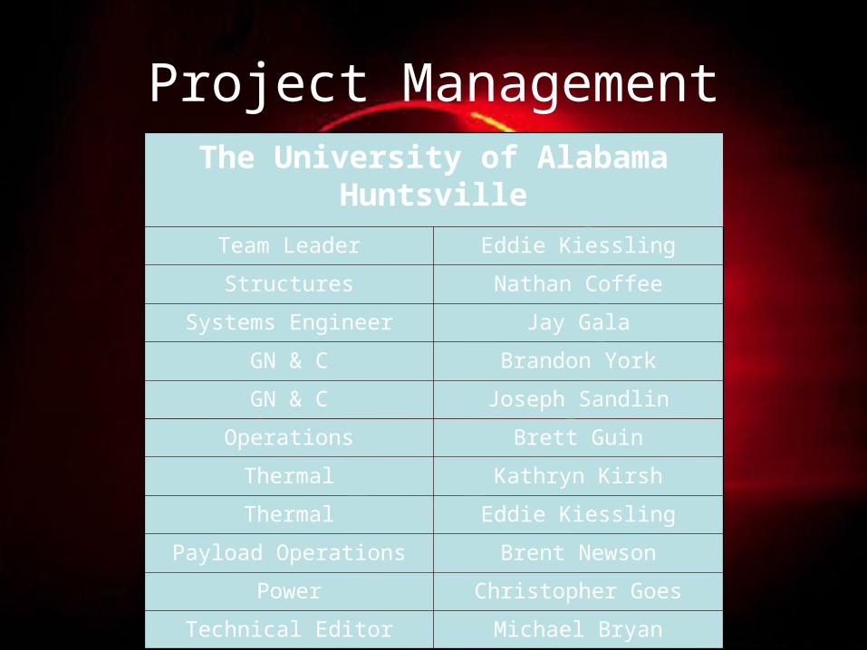
Project ManagementThe University of Alabama Huntsville
Team Leader Eddie Kiessling
Structures Nathan Coffee
Systems Engineer Jay Gala
GN & C Brandon York
GN & C Joseph Sandlin
Operations Brett Guin
Thermal Kathryn Kirsh
Thermal Eddie Kiessling
Payload Operations Brent Newson
Power Christopher Goes
Technical Editor Michael Bryan

Overview
• This Whitepaper seeks to establishes team roles, develop two alternative designs, and select one design as the final concept to take into Phase 3.
• The Viking Lander, the baseline design, for this project was compared to a Lander on Wheels (LOW) and a Lander with a Single Rover (LSR).
• Each concept was weighted against each other and utilizing Weighted Factor Analysis and Concept Evaluation Matrix to choose a final design.– Our results will show that the Lander on Wheels would be the
best approach.

Technical Description
• Overview of Phase 2:– Deliverable Items:
• White Paper– Summarizes the strategy for selecting alternative
systems– Qualitative/quantitative information to evaluate each idea– Logical rational for down selecting one concept among
the three concepts
• Oral Presentation– Summarizing information from the White Paper to
present to the review board.
Technical Description
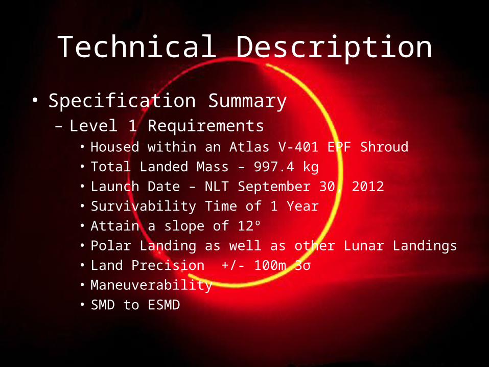
• Specification Summary– Level 1 Requirements
• Housed within an Atlas V-401 EPF Shroud• Total Landed Mass – 997.4 kg• Launch Date – NLT September 30, 2012• Survivability Time of 1 Year• Attain a slope of 12º• Polar Landing as well as other Lunar Landings• Land Precision +/- 100m 3σ• Maneuverability• SMD to ESMD

Specification Summary
– Critical Requirements• Launch Date• Mass• SMD to ESMD ratio• Landing Capabilities• Mobility

Team Eclipse Approach to Phase 2Baseline CDD
Mobility Trade SpaceViking 1 FOM
Customer
Systems Engineer and Team Lead
Power Payload Thermal Structures Operations GN&C
Analysis
Results
Description of Concepts
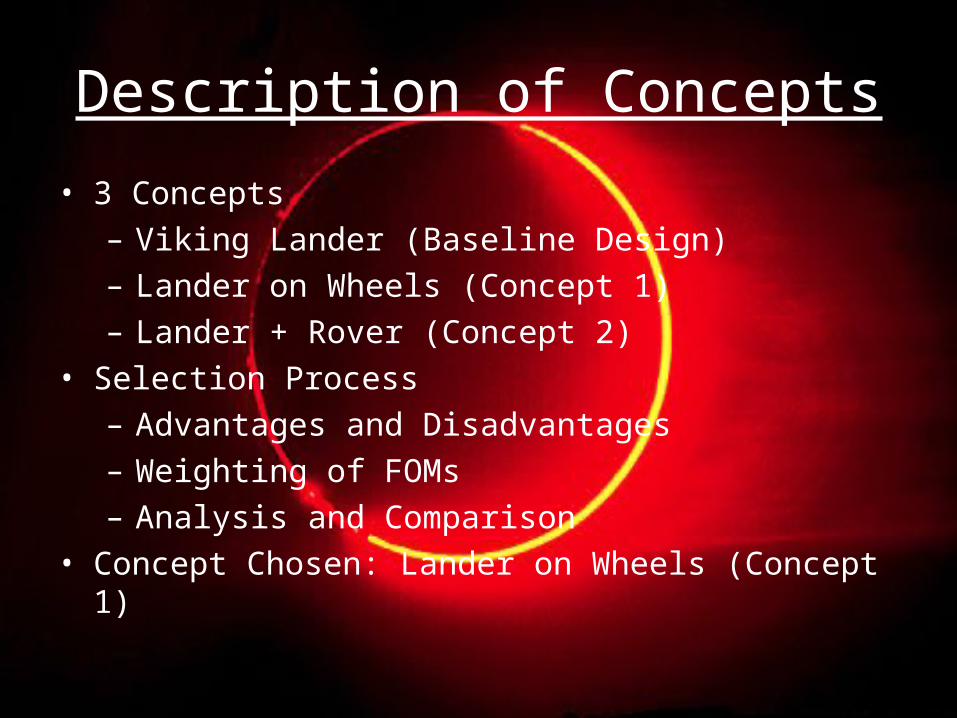
• 3 Concepts– Viking Lander (Baseline Design)– Lander on Wheels (Concept 1)– Lander + Rover (Concept 2)
• Selection Process– Advantages and Disadvantages– Weighting of FOMs– Analysis and Comparison
• Concept Chosen: Lander on Wheels (Concept 1)

Boost Matrix for Project 02Baseline Alternative Concepts
02-BL 02E-ALT1 02E-ALT2
Configuration Category
State Viking Lander on
Wheels Lander +
Rover
Power
RTG Lithium
NiCd Fuel Cell
RTG 2 RTGs
RTG & Rechargeable
Rover
RTG Radiation
Heater Regenerative
Thermal
Radiation
RTG (Heating)
Radiation (Cooling)
RTG (Heating)
Radiation (Cooling)
RTG (Heating)
Radiation (Cooling)
Composite Alloys
Titanium Structure
Aluminum
Aluminum And
Titanium Titanium
Titanium (Lander)
Composite (Rover)
LRO Payload Bay Sample/ Data
Acq./Transmissions Operations
Data Storage
Single Site Science
Multiple Site Science and
Samples
Single Site Science and Multiple Site
Samples
Travel to Sites GN&C
Landing Landing
Landing + Travel to Sites
Landing + Travel to Sites
Shroud (4 m) Payload Bay for
Samples Payload
SRV
N/A Shroud (4m)
SRV Shroud (4m)
SRV

02-BL “Viking”• Availability of Data• Martian Surface• Single Site Science Mission• Subsystems
– Thermal• Active & Passive
– Structural• Parachute, Bio-shield, & Aero-decelerator
– Redundant Communications– Power
• RTGs & Nickel-Cadmium Batteries– Guidance, Navigation, and Controls
• Three Axis Gyros and Accelerometer & Redundant x-axis system.
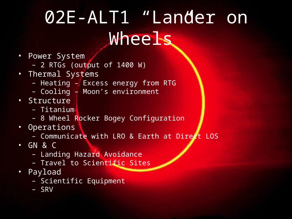
02E-ALT1 “Lander on Wheels”• Power System
– 2 RTGs (output of 1400 W)• Thermal Systems
– Heating – Excess energy from RTG– Cooling – Moon’s environment
• Structure– Titanium– 8 Wheel Rocker Bogey Configuration
• Operations– Communicate with LRO & Earth at Direct LOS
• GN & C– Landing Hazard Avoidance– Travel to Scientific Sites
• Payload– Scientific Equipment– SRV

02E-ALT2 “Lander + Rover”• Power System
– Lander: 1 RTG (output of 700 W)– Rover: Rechargeable battery system
• Thermal Systems– Lander: Heating – Excess energy from RTG– Rover: Heating – Energy from battery system– Lander and Rover: Cooling – Moon’s environment
• Structure– Lander: Titanium– Rover: Composite
• Operations– Communicate with LRO & Earth at Direct LOS
• GN & C– Lander: Landing Hazard Avoidance– Rover: Travel to and from Scientific Sites
• Payload– Scientific Equipment– Rover– SRV

Selection of Final Concept
• Criteria selection (in order of importance)– Technology Ratio– ConOps– Objectives Completed– Percent Payload– Surface Objectives Completed– Percent Power System
• Chosen Concept– Lander on Wheels (Alternative Concept 01)

Illustrations02-BL “Viking”

Illustrations02E-ALT1 “Lander on Wheels”

IllustrationsShroud Configuration

Video

Illustrations02E-ALT2 “Lander + Rover”
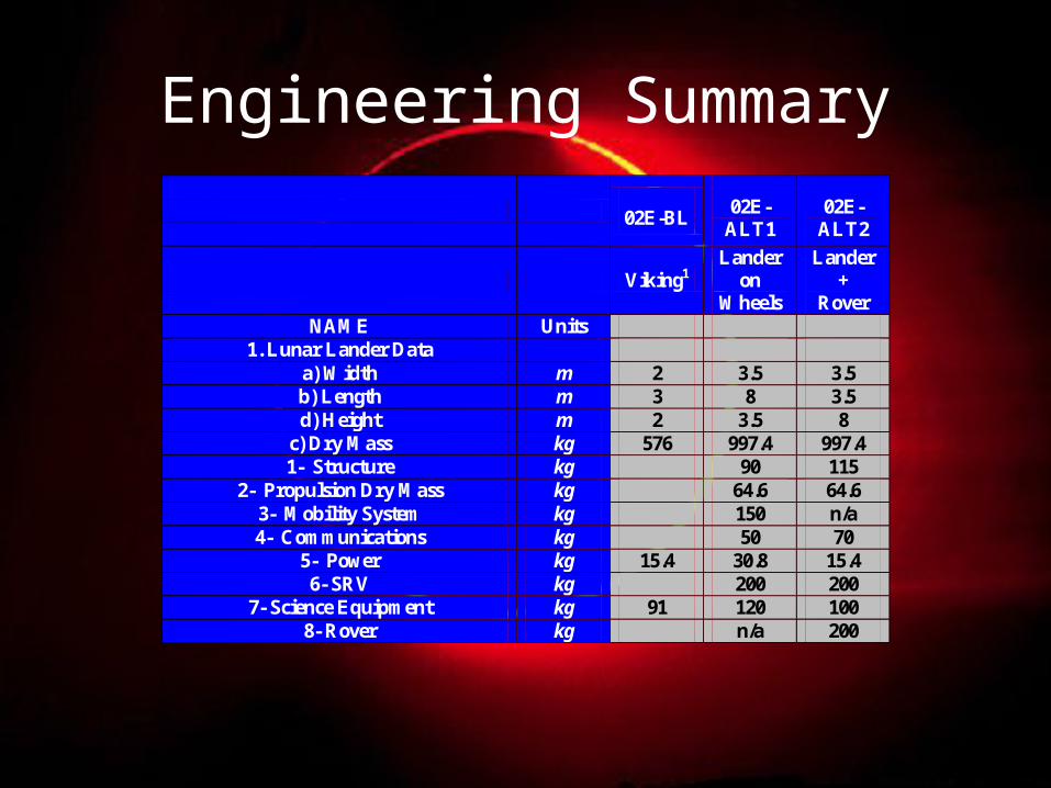
Engineering Summary
02E-BL 02E-
ALT1 02E-
ALT2
Viking1 Lander
on Wheels
Lander +
Rover NAME Units
1. Lunar Lander Data a) Width m 2 3.5 3.5 b) Length m 3 8 3.5 d) Height m 2 3.5 8
c) Dry Mass kg 576 997.4 997.4 1- Structure kg 90 115
2- Propulsion Dry Mass kg 64.6 64.6 3- Mobility System kg 150 n/a 4- Communications kg 50 70
5- Power kg 15.4 30.8 15.4 6- SRV kg 200 200
7- Science Equipment kg 91 120 100 8- Rover kg n/a 200
1 United States. National Aeronautics & Space Administration. Viking.
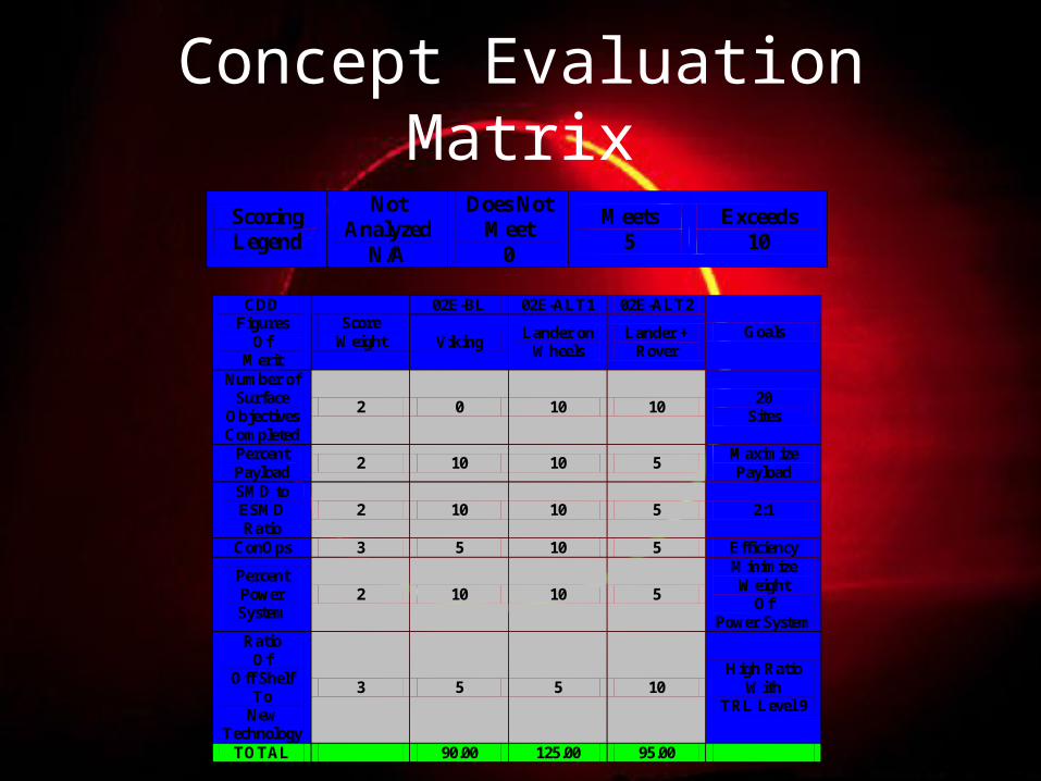
Concept Evaluation Matrix
Scoring Legend
Not Analyzed
N/A
Does Not Meet
0
Meets 5
Exceeds 10
02E-BL 02E-ALT1 02E-ALT2 CDD Figures
Of Merit
Score Weight Viking
Lander on Wheels
Lander + Rover
Goals
Number of Surface
Objectives Completed
2 0 10 10 20
Sites
Percent Payload
2 10 10 5 Maximize Payload
SMD to ESMD Ratio
2 10 10 5 2:1
ConOps 3 5 10 5 Efficiency
Percent Power System
2 10 10 5
Minimize Weight
Of Power System
Ratio Of
Off Shelf To
New Technology
3 5 5 10 High Ratio
With TRL Level 9
TOTAL 90.00 125.00 95.00

Phase 3 Plan
• Key Issues– Power Supply– Single Site Goals Issue– Finalize Mobility Concerns
• Tasks for Partner Universities– Southern University
• Rocker Bogie Suspension System• CAD Model of Mobility System
– ESTACA University• Design of SRV Propulsion System• CAD Model of SRV

Review
• Technical Description
• Description of Concepts
• Selection of Final Concept
• Phase 3 Plan