altitude measurement and calibration on milling
TRANSCRIPT

ALTITUDE MEASUREMENT AND CALIBRATION ON MILLING
OPERATION
NOR HANIS BINTI AHMAD NAZRI
Thesis submitted in fulfilment of the requirements
for the award of the degree of
Bachelor of Mechatronics Engineering
Faculty of Manufacturing Engineering
UNIVERSITI MALAYSIA PAHANG
JUNE 2013
vii
ABSTRACT
ADXL335 accelerometer is an electronic sensor which is used in detecting the
acceleration of a moving object in x, y and z axis. In this project the function of the
accelerometer had been applied on a platform which can be move in z-axis. This project
is all about developing a device where distance can be obtained by manipulating the
acceleration from accelerometer. Performing this task will contribute to certain
problems that need to be focus in order to get an accurate distance value, such as
unknown initial positions of the device on the platform and also the vibration on the
accelerometer. There are objectives that had been achieved in this project which
includes the implementation of the accelerometer application on shaker, development of
a device for accurate distance calculation using accelerometer, and comparison between
calculated distance values with the actual value of distance on shaker. First stage of this
project is where the accelerometer had been programmed by using a microcontroller
board, Arduino Uno. In this Arduino program, the analog reading from accelerometer
that had been recorded will be directly converted into acceleration in unit of m/ .
Simple circuit had been etched before being attached in the device box. During the
collection of data, actual distance is being recorded too, to be compared with the
calculated distance through double integration method. The device is placed on top of
the platform and the original position is being set up before the platform is moved
upward and the time is started to be recorded. By using this kind of method, the
acceleration and time will be recorded and as the output from this procedure, double
integration is being performed and the distance value calculated is being recorded. The
result from the calculated distance error will be compared to the actual data where here
the percentage error and standard deviation is being analysed. This project had been
done very well where all the objectives are a success with the results of average error of
0.27%.
viii
ABSTRAK
ADXL335 pecutan adalah sensor elektronik yang digunakan dalam mengesan pecutan
objek yang bergerak dalam paksi x, y dan z. Dalam projek ini fungsi pecutan itu telah
digunakan di atas pelantar yang boleh bergerak dalam paksi z. Projek ini adalah tentang
pembangunan peranti di mana jarak boleh diperolehi dengan menggunakan pecutan
daripada bacaan pecutan. Dalam melaksanakan tugas ini akan menyumbang kepada
masalah-masalah tertentu yang perlu menjadi tumpuan untuk mendapatkan nilai jarak
yang tepat, seperti kedudukan awal yang tidak diketahui peranti pelantar dan juga
getaran pada meter pecutan. Terdapat objektif yang telah dicapai dalam projek ini
termasuk pelaksanaan permohonan pecutan pada penggetar, pembangunan alat untuk
pengiraan jarak tepat menggunakan pecutan, dan perbandingan antara nilai jarak yang
dikira dengan nilai jarak yang sebenar pada jarak penggetar. Peringkat pertama projek
ini adalah di mana pecutan yang telah diprogramkan dengan menggunakan papan
mikropengawal, Arduino Uno. Dalam program Arduino ini, bacaan analog dari pecutan
yang telah dirakam secara langsung ditukar kepada pecutan dalam unit m/ . Litar yang
ringkas telah terukir sebelum dilekatkan di dalam kotak peranti. Semasa pengumpulan
data, jarak sebenar direkodkan untuk dibandingkan dengan jarak yang dikira melalui
kaedah integrasi berganda. Peranti ini diletakkan di atas pelantar dan kedudukan asal
yang ditetapkan sebelum pelantar akan digerakkan ke atas dan masa akan mula
direkodkan. Dengan menggunakan ini kaedah ini, pecutan dan masa akan direkodkan
dan sebagai keluaran daripada prosedur ini, integrasi berganda yang dilakukan dan nilai
jarak yang dikira akan direkodkan. Hasil dari kesilapan jarak yang dikira akan
dibandingkan dengan data yang sebenar di mana kesilapan peratusan dan sisihan piawai
akan dianalisis. Projek ini telah dijalankan dengan jayanya di mana semua matlamat
tercapai dengan hasil purata kesilapan 0.27%.

ix
TABLE OF CONTENTS
Page
EXAMINER APPROVAL ii
SUPERVISOR’S DECLARATION iii
STUDENT’S DECLARATION iv
DEDICATION v
ACKNOWLEDGEMENTS vi
ABSTRACT vii
ABSTRAK viii
TABLE OF CONTENTS ix
LIST OF TABLES xii
LIST OF FIGURES xiii
LIST OF FORMULA xvi
LIST OF SYMBOLS xvii
LIST OF ABBREVIATIONS xviii
CHAPTER 1 INTRODUCTION
1.1 Introduction 1
1.2 Project Synopsis 2
1.3 Problem Statement 3
1.4 Project Objectives 4
1.5 Project Scopes 4
1.6 Project Organization
5
CHAPTER 2 LITERATURE REVIEW
2.1 Introduction 6
2.2 Distance Calculation 6
2.2.1 Double Integration Method 6
2.2.2 Trapezoidal Methods 8
x
2.3 Calibration of Distance Using Accelerometer 12
2.4 Milling Operation 20
CHAPTER 3 RESEARCH METHODOLOGY
3.1 Introduction 25
3.2 Operational Flow Chart 26
3.3 Software 27
3.3.1 Proteus Virtual System Modelling (VSM) 27
3.3.2 Arduino Software 31
3.4 Hardware 34
3.4.1 Electronic Components 34
3.4.2 Milling Machine as a Platform for Experiments 37
3.4.3 CATIA Software for Device Casing 38
3.5 Mathematical Modelling 39
3.5.1 Double Integration Method 39
3.5.2 Percentage Error formula, %Error
41
CHAPTER 4 RESULTS AND DISCUSSION
4.1 Introduction 42
4.2 Verification of Hardware and Software 42
4.2.1 Experimental Setup 42
4.3 Result Analysis and Discussion 45
4.3.1 Calculation of distance 47
4.3.2 Calculation of Percentage Error, %e
48
CHAPTER 5 CONCLUSION AND RECOMMENDATIONS
5.1 Conclusion 51
5.2 Recommendations
52
REFERENCES 53

xi
APPENDICES
A Gantt Chart 56
B Arduino Program 59
C Data Collection 64
D Experimental Pictures 68

xii
LIST OF TABLES
Table No. Title
Page
3.1 List of Electronic Components
35
4.1 Tabulation of Collected Data
47
4.2 Calculation of Acceleration using Double Integration Method
48
4.3 Calculation of Percentage Error, %e
48
xiii
LIST OF FIGURES
Figure No. Title
Page
2.1 Trapezoidal method of numerical integration 8
2.2 Time histories of two periodic acceleration waveforms 10
2.3 Two traces correspond to the numerical integration calculation 10
2.4 The difference in the baseline which reveals the influence of the
added offset presents a linear drift
11
2.5 Displacements obtained by double integration 11
2.6 System utilized to obtain displacement from piezoelectric
accelerometer
12
2.7 Double integrator amplifier 13
2.8 Response from the output integrator and the actual
displacement
13
2.9 Simulation of the response of the integrator to a damped
sinusoid from an accelerometer
14
2.10 Adaptive noise cancellation 15
2.11 Output from accelerometer (upper) with the noise signal
(lower)
16
2.12 Time response of the adaptive filter with the noise of the signal
after filtering
17
2.13 Root Mean Square errors in position as a function of integration
time
19
2.14 The experimental Root Mean Square errors in position as
function of integration time for accelerometers
19
2.15 Plain Milling Machine Knee-type 21
2.16 Swivel cutter head Ram-type Milling machine 21
2.17 The concept of achieving and autonomous and intelligent NC
machine tool
22
2.18 Milling operation performed by DCM 23
xiv
2.19 MAKINO KE55 CNC Milling Machine 24
3.1 Operational Flow chart 26
3.2
The screenshot of Proteus Software 28
3.3 LCD I/O Peripheral 29
3.4 Simulation of the LCD I/O Peripheral 30
3.5
Circuit connection on breadboard between Arduino Uno with
LCD
30
3.6 ATMEGA328P simulation circuit in Proteus Software 31
3.7 Screenshot of the Arduino software 32
3.8
Flowchart of software development 33
3.9 Accelerometer ADXL355 35
3.10 Main-board of Arduino Uno 35
3.11
LCD 16 x 2 Alphanumeric display 36
3.12
UV PCB 36
3.13 Potentiometer 36
3.14
The attachments of accelerometer on top of the platform of the
Milling Machine
37
3.15
3D view of the device casing to be place on top of the Milling
Machine
38
3.16
Labelled part for components placement 38
4.1
Test run of the device on Milling Machine 43
4.2
Device is being run on platform (Milling Machine) for z-axis
direction at maximum height
44
4.3
Device is being run on platform (Milling Machine) for z-axis
direction at minimum height
44
4.4
Graph of z-axis analog signal acceleration from accelerometer
before applied low pass filter
45

xv
4.5
Graph of z-axis analog signal acceleration from accelerometer
after applied low pass filter
46
4.6 Analog signal acceleration from accelerometer before and after
applying low pass filter
46
4.7 Distance against Iteration for actual and calculated distance
49

xvi
LIST OF FORMULAS
Formula
No.
Title Page
2.1 First derivative 6
2.2
Second derivative 7
2.3 First integration 7
2.4
Distance of the movement 7
2.5 Double integration 8
2.6
Numerical integration calculation of the discrete signal in the
time domain
9
2.7 Computation of velocity 9
2.8
Computation of displacement 9
2.9 Steady-state accelerations 15
2.10
Frequency of oscillation 15
2.11 Frequency of noise 15
2.12
RMS errors 20
3.1 Formula for acceleration 39
3.2
Formula integration of acceleration to get velocity 39
3.3 Formula double integration of acceleration to get distance 40
3.4
Percentage Error 41

xvii
LIST OF SYMBOLS
a Acceleration
v Velocity
g Gravitational force
d Distance
m Meter
sec Second
f Frequency
Hz Hertz
t Time taken
xviii
LIST OF ABBREVIATIONS
COM Computer output on microfilm
LCD Liquid crystal display
VCC Voltage
GND Ground
PCB Printed circuit board
SPI Serial peripheral interface
DC Direct current
I/O Input output
USB
Universal Serial Bus
PWM
Pulse Width Modulation
ICSP
In Circuit Serial Programming
CNC Computer Numerical Control
RLS Recursive-least Squares
MEMS Microelectromechanical Systems
RMS Root Mean Square
CHAPTER 1
INTRODUCTION
1.1 INTRODUCTION
The current practice of measuring accurate distance travelled for an object often
use techniques with limitation, where it is very difficult to be used on variety purpose.
There is another way of measuring distance, laser displacement gauge which can
accurately measure small displacement, but then, the device is too expensive. Therefore,
there techniques in measuring distance, which is accelerometer. Accelerometer is a
device used to measure acceleration of a motion structure. From the acceleration, a
formula had been generated to obtain distance. Theoretically if one wanted to measure
vibration, either position, velocity or acceleration, it can be generate using integration
and differentiation.
Accelerometer is useful in measuring the amount of dynamic acceleration to
analyse the way the device is moving where, from the acceleration obtained it will
convert into velocity and the distance itself. Accelerometer used in this project is triple
axis accelerometer breakout ADXL335. The breakout board for the 3-axis ADXL335
from Analog Devices is a low noise and power consumption accelerometer. The sensor
range is within +/- 3g. The interface of the accelerometer is 3V with an output of analog
voltage for each three outputs.
There is another advantage in using the accelerometer for measurements, where
the size very small and can be easily attached to a body. It is also has wide frequency
and dynamic ranges. Accelerometer is measurement equipment because of its ability to
pick up high frequency content with high sensitivity.
The accelerometer will be program by using Arduino Uno which is a
microcontroller board that is based on the ATmega328. This type of arduino has 14
2
digital input/output pins of which 6 can be used as PWM outputs, six analog inputs, a
16 MHz ceramic resonator, a USB connection, a power jack, an ICSP header, and a
reset button. This board contains everything which will be needed to support the
microcontroller. It is simple to use by simply connect it to the computer with a USB
cable and control the input/output by program using its own compiler. The operating
voltage is 5V while the DC current per I/O Pin is 40 mA.
Milling Machine is the equipment for machining process of using a rotary cutter
in removing the material from a work piece. In advance, it can cut in a direction at an
angle with the axis of the tool. This equipment can be move in three positions including
x, y, and z axes. There are many types of Milling Machine exists, and one of it is CNC
Milling Machines. CNC Machines can exist in virtually any of the forms of manual
machinery like horizontal mills. Measurement and calibration of the altitude using
accelerometer on Milling Machine can be done with the results of acceleration of the
Milling Machine. The present of the accelerometer in the Milling Machine can be used
for inertial measurement of velocity and position, vibration and shock measurement,
and also measurement of gravity to determine the orientation of the Milling Machine. In
this project the main function of the accelerometer used on Milling Machine is inertial
measurement of velocity and position.
1.2 PROJECT SYNOPSIS
Accelerometer is main equipment which will be used along this project.
Therefore, in order to organize the schedule every detail works need to be done and it
includes few steps until final part. First of all, research on accelerometer is done before
further investigation on others, such as, distance calculation and application on Milling
Machine. The research includes its functions, how the accelerometer works, condition
of the accelerometer, specification of the accelerometer, and simple application of the
accelerometer. Accelerometer has a potential technique to measure acceleration, which
can then be converted to distance.
Accurate distance calculation of the Milling Machine motion is needed in order
to get the exact position. Accelerometer attached to the Milling Machine will help us in
recording the acceleration of the Milling Machine up and down. From the acceleration,
programming which had been structured will lead us in getting the exact distance of the
3
Milling Machine motion. Accelerometer functions in inertial measurement of velocity
and position where acceleration is single integrated for velocity and acceleration is
double integrated for position. Inertial measurements are non-contact method to
measure acceleration, velocity and distance travelled. Velocity is the integral of
acceleration while the distance is the integral of velocity which is also the double
integral of acceleration.
The projects continue with the research on Milling Machine. The research
includes the operation of the Milling Machine, and how the accelerometer being
connected to the Milling Machine. The Milling Machine operates in multiaxis motion.
Therefore, from the movement up and down of the Milling Machine, accelerometer is
attached to get the distance travel between the z-axis motions of the Milling Machine.
Measurements of distance is an advantage in manipulating the acceleration from
the accelerometer, it is physically small and can be easily attached to the Milling
Machine. In motion, acceleration is one of the measurements required because of its
ability to pick up high frequency and sensitivity, yet it is cheap and available in the
market. In order to gain the value of the distance, c-program for distance calculation
need to be build and run before combine the program with accelerometer to get the
acceleration.
Simulation of accelerometer is to be done after the research and build the c-
program of the distance and the acceleration. The simulation will be tested on actual
accelerometer in order to manipulate the acceleration value. If there is mistake after the
test, modification is needed before build the device. The test needs to be done many
times to make sure the consistency of the distance reading before test the device on
Milling Machine. Calibration of the distance data is done after completed the test on
Milling Machine, and followed by analysis of data.
1.3 PROBLEM STATEMENT
This project is all about developing a device which distance data can be found
from acceleration data through double integration. The focus is developing the device in
order to measure accurate distance calculation using accelerometer. Using integration
method errors exists, so from that minimization of the errors is needed so the distance
calculation is very close to the actual distance value. This device is attached to the
4
Milling Machine to get the reading of the acceleration from the motion of the machine.
Performing this task is easy, but there are certain problems that need to be focus in order
to get an accurate distance value. Firstly, there is the problem of unknown initial
positions of the device on the shaker and also the problem of vibration on the
accelerometer.
1. 4 PROJECT OBJECTIVES
There are three objectives had been identify in this study, there are:
1. To develop a device for accurate distance calculation using accelerometer.
2. To implement the accelerometer application on milling operation.
3. To compare the calculated distance value with the actual value on Milling
Machine.
1.5 PROJECT SCOPES
In order to finish this project, precise scope of work and proper plan needed to
be followed before it would achieve the objectives that had been structured. The scopes
of this study are:
1. Study on the application of accelerometer on Milling Machine.
2. Research on the development of the Milling Machine.
3. Design a device for accurate distance calculation using accelerometer.
4. Construct a program to convert the acceleration reading from analog to digital,
and voltage.
5. Perform conversion of the acceleration reading into distance using double
integration method.
6. Comparison between calculated distances with the actual distance on Milling
Machine.
5
1.6 PROJECT ORGANIZATION
In this thesis, there are five chapters presented. An overview of the following
chapters is as follows:
Chapter 1 is about the introduction of the calibration and accurate distance calculation
using accelerometer. In this chapter, the problem statement, objective and scope will be
identified.
Chapter 2 will discuss about the review of the literature that related to the title. It
reviews the application of accelerometer in various kind of device done by others
researcher.
Chapter 3 will discuss about the materials and methods that will be using in the project.
This chapter is all about the framework and approach of the project. It explains about
software and also the hardware that had been used to develop the project.
Chapter 4 will discuss about the result and discussion of the project. The result
included the project limitation, and result analysis.
Chapter 5 will discuss about the conclusion and future work of the project. This
chapter will briefly summarize the overall developed project.
CHAPTER 2
LITERATURE REVIEW
2.1 INTRODUCTION
This chapter summarize the stages which are related to the study from various
literatures review studied. The first section discusses the distance calculation using
accelerometer. Then it will followed by the calibrations of readings obtained from
accelerometer and the Milling Machine. All of the research in literature review will be
used as a guideline in calibration and accurate distance calculation using accelerometer.
2.2 DISTANCE CALCULATION
2.2.1 Double Integration Methods
Accelerometer is a small, thin, low power, complete 3-axis accelerometer with a
signal conditioned voltage outputs. Accelerometer measures acceleration with a
minimum full-scale range of ±3 g. Accelerometer also can measure the static
acceleration of gravity in tilt-sensing applications, as well as dynamic acceleration
which results from motion, shock, and vibration.
In this project, the requirement is to get the accurate distance calculation using
accelerometer. Therefore there are a few calculations involve in obtaining the distance
or position from the acceleration readings of the accelerometer. Double integration is
used for calculation as follows:
Position versus time of an object, x(t), the velocity, v(t), can be derive from the
first derivative, where :

7
( )dx
v tdt
(2.1)
From the first derivative, the second derivative is applied to get the acceleration, a (t).
2
2( )
d x dva t
dt dt (2.2)
The reverse of derivation is integration, from integration, double integration of
the acceleration, a(t), the initial position and initial velocity must be known. To get the
initial velocity, first integration should be applied.
0
0( ) ( ) ( )
t
t
v t v t a d (2.3)
From the equation above, , the initial time while the ( ), is the initial value of the
velocity where t = 0. To get the distance or position of the movement of the Milling
Machine itself the next formula is needed:
0
0( ) ( ) ( )
t
t
x t x t v d (2.4)
As a conclusion, in order to get the value of distance or exact position, double
integration of the acceleration need to be performed with the presents of the two
conditions, initial position and velocity [1].
In order to get a distance, the accelerometer must undergo a movement or
motion which will help it to sense the movement and give out acceleration reading.
Vibration is one of the example can used for the test. Vibration is a mechanical
oscillation. Mechanical oscillation is the motion around a reference point of
equilibrium. From the movement of the accelerometer, data on displacement or distance
through acceleration and velocity was obtained [2]. Single integration of acceleration
will give us velocity, while double integration will give us displacement or distance as
8
stated above [1]. Therefore the conversion process will be applied in analog integrators
hardware and software for double integration operation.
0 0
0 0( ) ( )
t t
c
t t
d t d v t dt a d (2.5)
Where:
: initial displacement, t = 0
: initial velocity, t = 0
: calculated displacement, t
2.2.2 Trapezoidal Methods
Equation (2.5) is being used for analog functions, functions which are
continuous. There are other numerical integration methods which can be used to obtain
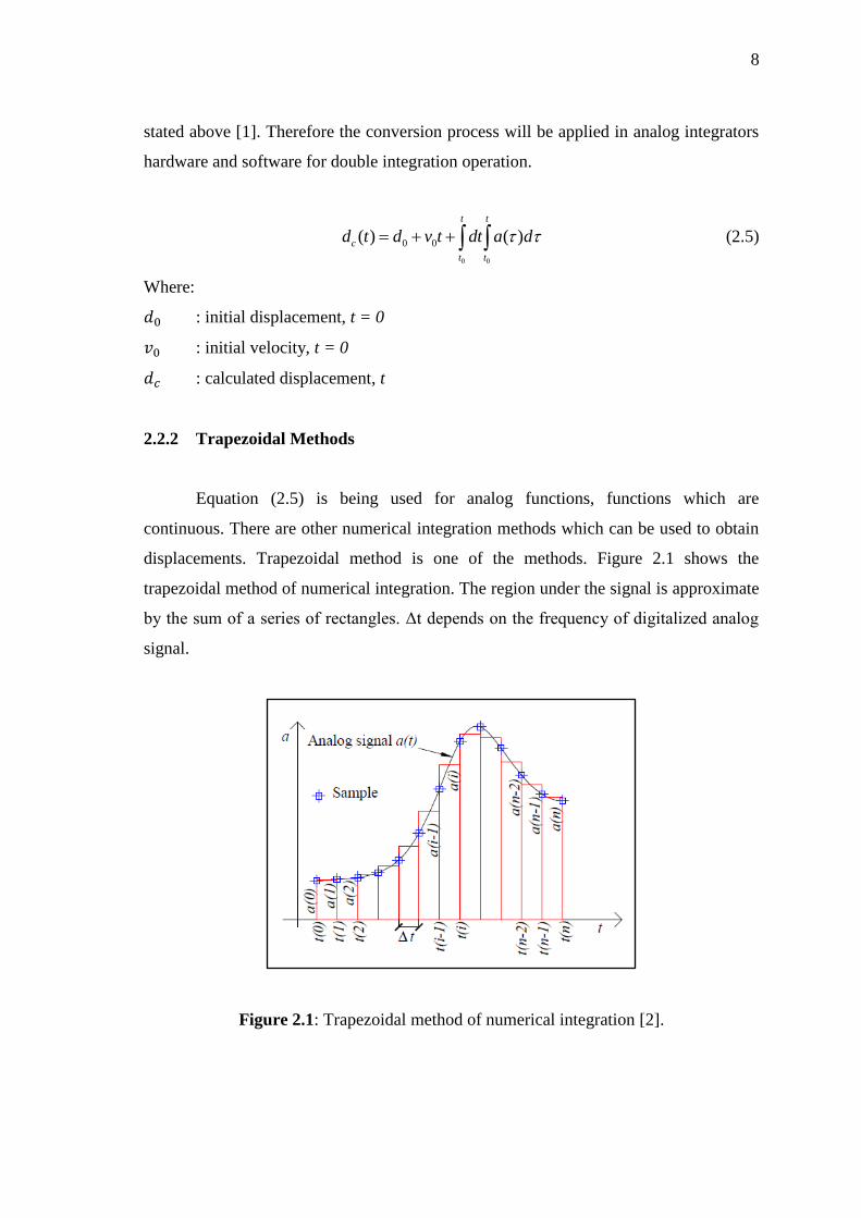
displacements. Trapezoidal method is one of the methods. Figure 2.1 shows the
trapezoidal method of numerical integration. The region under the signal is approximate
by the sum of a series of rectangles. Δt depends on the frequency of digitalized analog
signal.
Figure 2.1: Trapezoidal method of numerical integration [2].
9
Numerical integration calculation of the discrete signal in the time domain:
( )
1(0)
( 1) ( )( )
2
t n n
it
a i a ia t dt t
(2.6)
Where:
( ) : Continuous time domain waveform
( ) : ith
sample of the time waveform
: Time increment between samples (t(i)-t(i-1))
n : number of samples of the digital record
From the above equations, we can calculate the displacements. Computation of the
velocity from acceleration is needed before followed by displacement computation.
( 1) ( )( ) ( 1)
2c c
a i a iv i v i t
(2.7)
( 1) ( )( ) ( 1)
2c c
v i v id i d i t
(2.8)
Where:
( ) : ith
sample of the acceleration waveform
( ) : ith
sample of the calculated velocity
( ) : ith
sample of the calculated displacement
Example of numerical integration which shows the double integration effects on the
waveform.
10
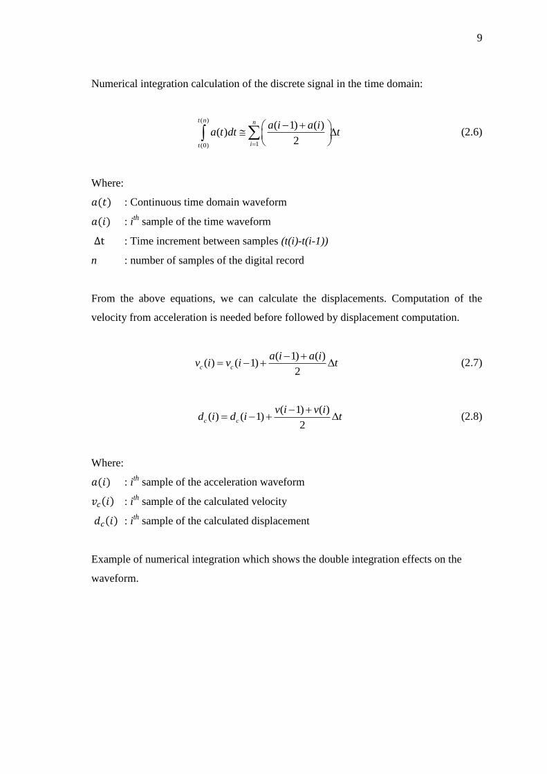
Figure 2.2: Time histories of two periodic acceleration waveforms [2].
Figure 2.3: Two traces correspond to the numerical integration calculation [2].
11
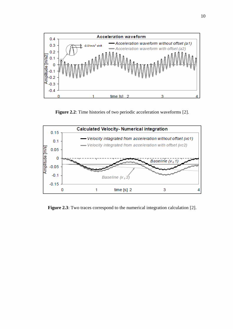
Figure 2.4: The difference in the baseline which reveals the influence of the added
offset presents a linear drift [2].
Research is done by the attachment of accelerometers on a moving plate to gain
the results. From the experiments displacements obtained by double integration can be
seen from Figure 2.5.
Figure 2.5: Displacements obtained by double integration [2].
The accelerometer is suitable to measure low frequency signals with high
resolution. It is shown that the conversion of acceleration into displacement using
numerical double integration can be done successfully [2]. Double integration in time

12
domain can be achieved by scaling the discrete Fourier transform of the measured
acceleration signal in frequency domain [3].
2.3 CALIBRATION OF DISTANCE USING ACCELEROMETER
The correlation of displacement is much easier rather than correlating the
accelerometer in studying a large structure. Measured displacement is proportional to
the stresses in elastic structure and can be used directly in determining the accumulated
damage. Displacement is more difficult to be measured than accelerations as the devices
used to measured are non-inertial and we need a fixed reference to work properly, but
by using accelerometer the measurement of displacement can be done easily using
double integration technique. Unfortunately there are many problems that will cause
errors in the results [4]. Therefore, calibration is needed to fix the errors.
Figure 2.6: System utilized to obtain displacement from piezoelectric
accelerometer [4].
A modelled consists of piezoelectric accelerometer and amplifier charge system
which provide analog double integration is used to measure displacements. Figure 2.6
shows how the system works in obtaining the displacements. The integrator stage is
where is where the user can choose the quantity to be measured.
Piezoelectric
accelerometer
Input
amplifier Low pass
filter Integrator
Output
amplifier
Change amplifier model 2636
Vo