alto 818sc / alto 818sx security management system · alto 818sc / alto 818sx security management...
TRANSCRIPT
Alto 818SC / Alto 818SXSecurity Management System
8-door controller
A/E Guideform SpecificationVersion 1.0

WSE • 3/21/97 16720 — ii Alto 818 Access Control System
NOTES:
• The following A/E Guideform Specification conforms to CSI guidelines to provide Specifiers an easy way toinclude Westinghouse Security Electronics products in their specifications.
• The specifier should carefully select the portions of this document that fit the intended application.
• Feel free to consult with your Westinghouse Security Electronics systems integrator regarding yourparticular application.
• Optional feature choices are represented by items enclosed in brackets [ ].
• This document is considered accurate through the date on the cover. For updated specifications, callWestinghouse Security Electronics at 408 727-6521, or visit the WSE Web page atHTTP://WWW.WSEinfo.com .
• The following individuals and organizations contributed to this document:
Editor/project team leader:- Brent A. Duncan, Marketing Publications Specialist
Core team members:- Joe Bridgman, Area Sales Manager- Brian Giampaoli, Area Sales Manager- Joe Oesterle, US Sales Manager
With contributions by:- Frank Binzoni, VP Sales & Marketing- Ken Butte, Project Manager/Readers and Cards- Bill Blasdell, VP Engineering- James Collins, Senior Design Engineer- Dana Frischer, Area Sales Manager- Susan Goldin, Technical Writer- Tim Hillbun, System Test & Evaluation Manager- Peter Keep, Marketing Services Manager- Steve Lever, Field Service Engineer- Troy Mickle, Marketing Communications Specialist- Jim Reeve, Software Engineer- Alec Ratliff, Field Service Engineer- Bill Richardson, Technical Instructor- Ping Saye, Design Enginerring Manager- Tony Smith, Software Engineer- George Souza, Project Team Director- Rick Sparks, Project Manager/Controllers- Matt Wenzel, Field Service Manager
With special thanks to:- John Suhr, Engineering Director, Tomasi-Dubois & Assoc. Sec. Consultants- Construction Services Institute

WSE • 3/21/97 16720 — iii Alto 818 Access Control System
Table of Contents
PART I GENERAL................................................................................................................................................................1.1 SECTION INCLUDES........................................................................................................................................1
A. Section includes specifications for an integrated security management systemwhich shall perform the following general services: ..........................................................11. Access control. ......................................................................................................................12. Alarm monitoring. ................................................................................................................13. Reporting functions. .............................................................................................................14. Security management functions. ........................................................................................1
.2 SYSTEM DESCRIPTION ...................................................................................................................................1A. Access Control System:....................................................................................................................1
1. Access management system (System) shall monitor and control access toareas defined herein. .................................................................................................1
2. System shall be capable of supporting multiple access control technologiesat each door, as well as alarm inputs and control outputs. .................................1
3. System shall consist of a microprocessor based controller, card readersand/or Keypads [and host software]. .......................................................................1
4. System shall be capable of operating with or without host software station. .............15. Specific types of devices and their functions shall be addressed in relevant
sections. .......................................................................................................................1B. Description of work: .........................................................................................................................1
1. The Systems Integrator shall include all necessary labor, tools, equipment,and ancillary materials required to furnish and install a complete andoperational access control and alarm monitoring system...................................1
2. Access Control System will manage access to [building] [and] [selectedareas] using [encoded cards.] [and/or] [coded Keypads.] .....................................1
3. The extent of Access Control System work is defined to include, but not byway of limitation: .......................................................................................................1
4. Requirements are indicated elsewhere in these specifications for workincluding, but not limited to, raceways and electrical boxes andfittings required for installation of control equipment and wiring: notthe work of this section. ............................................................................................1
.3 SUBMITTALS.....................................................................................................................................................1A. Product Data: Submit for prior approval, [__________] copies of manufacturer’s
data on Proximity or Magnetic Stripe Access Control System and components. ............1B. Shop Drawings: Submit dimensioned drawings of [proximity] [and/or] [Magnetic
Stripe] [and/or] [Keypad] Access Control System and accessories including,central controller, external keyboard and printer, [proximity card readingsensors] [or magnetic stripe card readers,] [Keypads,] power suppliesswitches and ancillary equipment. ........................................................................................1
C. One Line Diagram: Submit a one line diagram of the system configurationproposed if it differs from that illustrated in the riser diagram included inthese specifications. Submittals indicating typical riser diagrams are notacceptable. .................................................................................................................................2
D. Operator’s Manual: Submit for prior approval, [__________] copies ofmanufacturer’s manual for programming and operating the Alto 818SC/SXsystem and its related components. ......................................................................................2
.4 QUALITY ASSURANCE:....................................................................................................................................2A. Manufacturer: Manufacturer of products defined in this section must have: .........................2
1. Industry experience: Company must have at least 20 years experience inmanufacturing and servicing access management systems. ...............................2
2. ISO 9001 Certification: Manufacturing process of company must meetstringent standards of ISO 9001 Certification.........................................................2
B. Systems Integrator: ..........................................................................................................................21. Company with a minimum of [5 (five)] years system design, engineering
supervision, and installation experience in the alarm, buildingautomation, or Access Control industry. ................................................................2
2. Company that is trained and authorized to install manufacturer products. ................2C. System Checkout: .............................................................................................................................2
1. Pre-testing: All components and assemblies of the control unit are to bepre-tested at the factory prior to shipment. ............................................................2
2. Burn-in: 1,000 hours at normal operating conditions or equivalency. ........................23. On-site testing: Manufacturer trained and authorized Systems Integrator
shall functionally test each component in the system after

WSE • 3/21/97 16720 — iv Alto 818 Access Control System
installation to verify proper operation and confirm that the panelwiring and addressing conform to the wiring documentation........................... 2
4. Service facility: Systems Integrator shall have service facilities within[_____] miles of the installation. .............................................................................. 2
D. Regulatory Requirements: ............................................................................................................. 21. NEC Compliance: All electrical wiring work shall comply to NEC. ........................... 22. NEMA Compliance: Electrical equipment shall comply with applicable
portions of NEMA. ..................................................................................................... 23. FCC Emissions: All assemblies shall be in compliance with FCC emission
standards. ................................................................................................................... 24. UL-1012 and CSA: All power supplies shall be in compliance with
Underwriters Laboratories standard 1012 and CSA standards forpower supplies........................................................................................................... 2
5. [UL-294: The system shall comply with Underwriters Laboratoriesstandard 294 for Access Control Systems. (Alto 818 SX only)] ............................ 2
E. Warranty: .......................................................................................................................................... 21. Analog Proximity Command Cards: No less than 5 (five) years. .................................. 22. Digital Command Cards: No less than 1 (one) year. ...................................................... 23. System Components: 15 (fifteen) months from shipment date or 12
(twelve) months from date of purchase by Systems Integrator,whichever comes first. ............................................................................................. 2
PART II PRODUCT.............................................................................................................................................................. 3.1 MATERIALS & COMPONENTS ...................................................................................................................... 3
A. System Description: ........................................................................................................................ 31. The Access Control and Security system within the building shall consist of
a microprocessor based controller that can be either a standalone ora networked unit with means to program, monitor intrusion andlimit access to a single, or a series of, one-door to eight-doorcontrolled areas. ........................................................................................................ 3
2. A single system shall support up to 8 (eight) card reading sensors [and/orKeypads] and up to 8 (eight) modules of 4 (four) inputs each. ........................... 3
3. Cards: .................................................................................................................................... 34. Keypad modes:.................................................................................................................... 35. The Access Control and Security System shall provide complete software
and hardware to operate with the following features: ......................................... 3B. Hardware features: .......................................................................................................................... 4
1. Access Controller (Alto 818 SC / Alto 818 SX): .............................................................. 42. Multiple Switch Monitor (774A): ..................................................................................... 53. Annunciator Control Module (778A): ............................................................................ 64. Digital Proximity Key Reading Sensor (DigiReader): ................................................ 75. Keypad (VIP-2): .................................................................................................................. 86. Analog Proximity Card Reading Sensor (SE 2800 Series): ......................................... 97. Analog Proximity Card Reading Sensor—Compact Model (2804): ......................... 108. QuadraKey Digital Proximity Command Card: ........................................................ 119. NexKey Digital Proximity Command Card: ............................................................... 1110. DuraKey Digital Proximity Command Card: .......................................................... 1211. Analog Proximity Command Card ([SE 1050] [SE1060]): ...................................... 1312. Power Supply, Controller (3018): ................................................................................ 1313. Power Supply with battery backup, Controller (3718S or 718SUL): .................... 1414. Power Supply (PI-1): ...................................................................................................... 1415. Accessories ....................................................................................................................... 15
C. Controller software features: ....................................................................................................... 161. Control operation: Based on the ability to force relay lock outputs to an
operating mode. Forcing action may be initiated by: ......................................... 162. Access Codes: .................................................................................................................... 163. Holidays: ............................................................................................................................ 164. Card Commands: The user shall be able to define command cards
according to the following parameters:................................................................ 165. Card functions: Card functions shall include: ............................................................. 166. Monitoring (if monitoring module is required): .......................................................... 177. Annunciation (if Annunciator is used): ........................................................................ 178. Alarm Shunting: ............................................................................................................... 179. Forced Entry Alarms: ...................................................................................................... 1710. Passwords: ....................................................................................................................... 17

WSE • 3/21/97 16720 — v Alto 818 Access Control System
11. Printed Data Output: System shall be capable of selecting which accessand monitor point activity messages are to be output the printer. Thesystem shall be capable of printing the following information:........................18
12. Sensors:..............................................................................................................................1813. Dial-up:..............................................................................................................................1814. Telecommunications: ....................................................................................................18
PART III EXECUTION .......................................................................................................................................................18.1 EQUIPMENT INSTALLATION AND DOCUMENTATION .........................................................................18
A. Installation: ......................................................................................................................................181. The Proximity Access Control and Alarm Monitoring System shall be
installed and wired completely as shown on the plans by a trainedand authorized Westinghouse Security Electronics SystemsIntegrator. ..................................................................................................................18
2. Systems Integrator shall make all necessary wiring connections toexternal devices and equipment. ...........................................................................18
B. Telephone Lines: ............................................................................................................................181. The owner shall arrange for dedicated or dial-up telephone lines for the
telecommunications equipment as shown on the plans. ..................................182. Each phone line shall be terminated in an RJ-11 telephone jack. ..............................183. Note: Any connections to the public telephone system require
notification of the local telephone company. See Specificinstructions in manual for modem used...........................................................18
C. Documentation: ..............................................................................................................................191. Accurate “as built” drawings shall be furnished by the Systems Integrator
to aid the owner in programming. These should indicate the door(s)controlled by each lock output, the monitoring points for the doorcontrolled area, and any annunciator outputs or special inputs intothe system. ................................................................................................................19
2. The Systems Integrator shall supply operating and maintenance manualsto aid the owner in the programming of the system...........................................19
.2 SERVICE AND SUPPORT................................................................................................................................19A. Startup:..............................................................................................................................................19
1. After the system has been installed, the documentation delivered to theowner and the telephone lines are operational in compliance withPart III.1 above, the Systems Integrator shall verify correct operationof all system components. ......................................................................................19
2. The Systems Integrator shall guarantee all material and workmanshipinvolving the system for up to [_____] year after startup. ...................................19
B. Training: ...........................................................................................................................................191. After system startup, the Systems Integrator shall instruct owners
personnel in how to program the system and demonstrate a typicaloperating program for a single door controlled area. .........................................19
C. Warranty Support:..........................................................................................................................191. The Authorized Systems Integrator shall be available during the warranty
period to answer programming and application questions to supportowners personnel during this period. ..................................................................19
2. [Option: The Authorized Systems Integrator shall have capability to have aremote terminal for programming the Access Controller to supportthe owner’s personnel during this period. The owners system shallinclude a modem SE Model # 5200 or equal, necessary cabling andtelephone extension to support this telecommunications operation.] ............19
3. [Option: The Authorized Systems Integrator shall have the training andcapability to provide additional support services including: .............................19
PART IV APPENDIX............................................................................................................................................................A.1 READ RANGE MATRIX...................................................................................................................................A.2 MOUNTING DIAGRAMS .................................................................................................................................A
A. Alto 818SX/Alto 818SC: ....................................................................................................................AB. Multiple Switch Monitor (774-A): .................................................................................................BC. 778 Annunciator Control Module (Annunciator): ...................................................................C
.3 SAMPLE SYSTEM DIAGRAMS ...................................................................................................................... DA. Alto 818 SC Digital Proximity with Keypad: ............................................................................. DB. Alto 818SX Analog Proximity with Keypad:...............................................................................E

WSE • 3/21/97 16720 — vi Alto 818 Access Control System
Alto 818SC / Alto 818SX Security Management SystemA/E Specification Summary• Access Control Ports: 8
• Unsupervised Monitor Points:1 9 maximum
• Supervised Monitor Points:2 32 maximum
• Outputs, Lock and Auxiliary: 16 maximum
• Cards without names: 11,200
• Cards with names: 4,400
• Access Codes: 120
• Event Report Schedules: 32
• Transaction Buffer: 4,000 transactions
• Card Technology: - Digital Proximity
- Analog Proximity
- Keypad
• Operator Interface Methods: - Terminal: RS232/ASCII Protocol
- Host: RS232 or 20mA/ASCII, modem orSEEP protocol
• Communications to Keypad: - 1 RS 485 Ports
Twisted pair
• Regulatory Approval: FCC, UL-1012, CSA, UL 294
• Environmental: The controller shall be designed tooperate properly within relative humidityrange of 0% to 90% non-condensing andwithin a temperature range of 20° to120° F (-7° to +50° C).
1 keypad and Controller tamper only.2 via MSM only.

WSE • 3/21/97 16720 — 1 Alto 818 Access Control System
PART I GENERAL
.1 SECTION INCLUDES
A. Section includes specifications for an integrated security management system which shall performthe following general services:
1. Access control.
2. Alarm monitoring.
3. Reporting functions.
4. Security management functions.
.2 SYSTEM DESCRIPTION
A. Access Control System:
1. Access management system (System) shall monitor and control access to areas defined herein.
2. System shall be capable of supporting multiple access control technologies at each door, as wellas alarm inputs and control outputs.
3. System shall consist of a microprocessor based controller, card readers and/or Keypads [and hostsoftware].
4. System shall be capable of operating with or without host software station.
5. Specific types of devices and their functions shall be addressed in relevant sections.
B. Description of work:
1. The Systems Integrator shall include all necessary labor, tools, equipment, and ancillarymaterials required to furnish and install a complete and operational access control and alarmmonitoring system.
2. Access Control System will manage access to [building] [and] [selected areas] using [encodedcards.] [and/or] [coded Keypads.]
3. The extent of Access Control System work is defined to include, but not by way of limitation:
a. [_____] central controllers.
b. [_____] external keyboard and printer (directly or via central host).
c. [_____] proximity card reading sensors.
d. [_____] Keypads.
e. [_____] input monitoring modules.
f. [_____] output relay modules.
g. Wiring, power supplies, switches and ancillary equipment.
4. Requirements are indicated elsewhere in these specifications for work including, but not limitedto, raceways and electrical boxes and fittings required for installation of control equipment andwiring: not the work of this section.
.3 SUBMITTALS
A. Product Data: Submit for prior approval, [__________] copies of manufacturer’s data on Proximity orMagnetic Stripe Access Control System and components.
B. Shop Drawings: Submit dimensioned drawings of [proximity] [and/or] [Magnetic Stripe] [and/or][Keypad] Access Control System and accessories including, central controller, external keyboard andprinter, [proximity card reading sensors] [or magnetic stripe card readers,] [Keypads,] power suppliesswitches and ancillary equipment.

WSE • 3/21/97 16720 — 2 Alto 818 Access Control System
C. One Line Diagram: Submit a one line diagram of the system configuration proposed if it differs fromthat illustrated in the riser diagram included in these specifications. Submittals indicating typical riserdiagrams are not acceptable.
D. Operator’s Manual: Submit for prior approval, [__________] copies of manufacturer’s manual forprogramming and operating the Alto 818SC/SX system and its related components.
.4 QUALITY ASSURANCE:
A. Manufacturer: Manufacturer of products defined in this section must have:
1. Industry experience: Company must have at least 20 years experience in manufacturing andservicing access management systems.
2. ISO 9001 Certification: Manufacturing process of company must meet stringent standards of ISO9001 Certification.
B. Systems Integrator:
1. Company with a minimum of [5 (five)] years system design, engineering supervision, andinstallation experience in the alarm, building automation, or Access Control industry.
2. Company that is trained and authorized to install manufacturer products.
C. System Checkout:
1. Pre-testing: All components and assemblies of the control unit are to be pre-tested at the factoryprior to shipment.
2. Burn-in: 1,000 hours at normal operating conditions or equivalency.
3. On-site testing: Manufacturer trained and authorized Systems Integrator shall functionally testeach component in the system after installation to verify proper operation and confirm that thepanel wiring and addressing conform to the wiring documentation.
4. Service facility: Systems Integrator shall have service facilities within [_____] miles of theinstallation.
D. Regulatory Requirements:
1. NEC Compliance: All electrical wiring work shall comply to NEC.
2. NEMA Compliance: Electrical equipment shall comply with applicable portions of NEMA.
3. FCC Emissions: All assemblies shall be in compliance with FCC emission standards.
a. Microprocessor based controller: Part 15, Subpart F, Class A.
b. Proximity Card Reading Sensors: Part 15, Subpart F (field disturbance sensors).
c. Dial-up modems: Part 68.
4. UL-1012 and CSA: All power supplies shall be in compliance with Underwriters Laboratoriesstandard 1012 and CSA standards for power supplies.
5. [UL-294: The system shall comply with Underwriters Laboratories standard 294 for AccessControl Systems. (Alto 818 SX only)]
E. Warranty:
1. Analog Proximity Command Cards: No less than 5 (five) years.
2. Digital Command Cards: No less than 1 (one) year.
3. System Components: 15 (fifteen) months from shipment date or 12 (twelve) months from date ofpurchase by Systems Integrator, whichever comes first.

WSE • 3/21/97 16720 — 3 Alto 818 Access Control System
PART II PRODUCT
.1 MATERIALS & COMPONENTS
A. System Description:
1. The Access Control and Security system within the building shall consist of a microprocessorbased controller that can be either a standalone or a networked unit with means to program,monitor intrusion and limit access to a single, or a series of, one-door to eight-door controlledareas.
2. A single system shall support up to 8 (eight) card reading sensors [and/or Keypads] and up to 8(eight) modules of 4 (four) inputs each.
3. Cards:
a. Digital Proximity: QuadraKey, DuraKey, NexKey.
b. Analog Proximity: 1030, 1040, 1050, 1060 cards.
4. Keypad modes:
a. Standalone mode with user entered card number for access, or
b. In conjunction with sensor for dual verification entry.
5. The Access Control and Security System shall provide complete software and hardware to operatewith the following features:
a. Database: Database shall store all user operating data and handle event reporting for allpossible attached devices, and shall contain memory capacity for the following:
1) Users with unique ID: 11,200.
2) Users with 12 character name and unique numeric ID: up to 4,400.
b. Event activity: System shall designate activity as an alarm or non-alarm condition, dependentupon modules installed, and shall report activity for:
1) Supervised monitor points: 32 maximum.
2) Unsupervised monitor points: 9 maximum.
3) Outputs: 16 maximum.
c. Relay outputs: System shall initiate relay output commands based on:
1) Card Access Activity.
2) Operator Keyboard Inputs.
3) Pre-programmed Time Schedule.
4) Switch Input.
d. System diagnostics:
1) Automatic system diagnostics and automatic alarming based on detected faults in thecontroller, sensors, wiring, and multiple switch monitor.
2) Off-line diagnostics for checking the integrity of controller’s memory (RAM and ROMtest), annunciator control test and radio frequency interference test.
e. Communication modes: System shall communicate activity in either of two modes, asfollows:
1) Standalone mode: In standalone mode, all system activity messages to the operator shallbe printed in plain English Language Text. Mnemonic type or transaction code typeoperator messages are not acceptable, or;
2) Networked mode: In networked (Host) mode, the Alto 818SC/SX will be polled by a Hostsystem for activity messages. All system activity messages to the Host system shall bebinary for efficient data communications supporting SEEP protocol. The Host shall havethe responsibility for acknowledging and translating the received messages. Whileoperating in Host mode, a second port on the Controller shall be available for standalonemode connection and output.

WSE • 3/21/97 16720 — 4 Alto 818 Access Control System
f. Battery back-up: The Access Control and Security System shall include internal batterybackup to maintain controller database, program, time, date, and building mode during apower loss.
g. Passwords:
1) The System shall utilize passwords.
2) A password must be used by operator to gain access to the system commands.
3) Authorization levels: Each password shall be assigned to one of 6 (six) authorizationlevels.
4) Operator passwords defined: up to 8 (eight).
5) Duplication: If a password is duplicated, the Alto 818SX/SC will only recognize the firstoccurrence.
h. Pre-programmed: The Access Control and Security System shall have WSE pre-programmeddefault data for ease in start-up and testing of equipment.
i. Transaction buffer: 4,000 transactions, minimum.
j. Off-site programming: The Access Control and Security System shall allow for off-siteprogramming via dial-up modem.
k. Automatic dial-up: The Access Control and Security System shall provide means of usingautomatic “dial-up” smart modem to automatically report alarms or send messages to remoteterminals.
l. Disk backup: The Access Control and Security System shall allow for disk backup andrestoration of user data in the event of database loss.
m. Modular components: The Access Control and Security System shall be such that itscontroller(s) are modular and expandable in design so that it can accommodate facilitygrowth.
B. Hardware features:
1. Access Controller (Alto 818 SC / Alto 818 SX):
a. General: The [Alto 818SX] [Alto 818SC] (Controller) shall be a microprocessor based, 8 (eight)door controller that provides the following functions in the System:
1) Provides central control for all devices attached.
2) Makes decisions for access.
3) Responds to monitor activity.
4) Receives input to control its decision making.
5) Reports activity to other devices.
b. Capacities:
1) Addressable devices: Via coaxial cable or twisted pair, Controller shall have followingcapacities:(i) Analog Proximity sensors: up to 8 (eight) via coaxial cable.
(ii) Digital Proximity sensors: up to 8 (eight) via twisted pair.
(iii) Keypads: up to 8 Keypads.
2) Contact inputs: up to 32 contact inputs for alarm and status reports via coax.
3) Controller shall provide for operation of electrified locking hardware by means contactfused relays, each with a rating of 3 amps.
4) Controller shall have means to connect a remote annunciator control module with 8(eight) output alarm contacts and 1 master latched alarm contact. Module shall also havebuilding mode indicator and mode selector switch and remote switch connections.
c. Specifications:
1) Dimensions: 18 in. X 10.5 in. X 2.3 in. (45.7 X 26.7 X 5.8 cm).

WSE • 3/21/97 16720 — 5 Alto 818 Access Control System
d. Mounting:
1) The Controller shall be capable of being wall mounted.
2) All wiring connections shall be provided at the top and right side of the unit for ease ofaccess.
3) The front cover, containing 6 self-contained screws, shall remove for access to internalswitches and parts.
e. Power:
1) Source: Power is provided via wiring from a Power Supply unit (see section 2 or 3).
2) Consumption: 650 mA at 16 volts AC and 500 ma at 25.2 volts AC input (typical).
3) Battery: A low voltage battery shall maintain the internally stored database setup whenno power is available to the controller.
f. Wiring:
1) Host, terminal or printer: 2 (two) 9-pin female Phoenix.
2) RS-485 (for Keypads and/or digital proximity readers): Phoenix.
3) 20mA communications to other Controllers or to host system: Phoenix.
4) Power supply: Phoenix.
5) Output relays: Phoenix.
6) Annunciator (778): 15-pin D-subminiature.
g. Communication:
1) ASCII encoded data: 2 (two) RS-232 data I/0 ports.
2) Host communication: 1 (one) RS-232 port shall provide for Host communication utilizingHOST or SEEP Protocol.(i) Note: Both of the above ports shall be usable for a terminal / printer.
3) Networking with other Controllers and Host systems: 1 (one) 20mA data I/O port forconnecting to other Controllers and Host systems.
h. Feedback: LED status lights indicate:
1) Controller CPU operational status.
2) Lock status.
3) Communication status.
4) Alarm status.
5) Readiness of entry Keypad and program mode.
i. Diagnostics: LED status lights shall indicate:
1) Operational status of the controller.
2) Door status and lock status of controlled entries.
j. Self-protection: The Controller shall have inputs to detect:
1) Power input failures.
2) Controller tampering.
k. Manufacturer: Westinghouse Security Electronics Model [ALTO 818SX] or [ALTO 818SC].
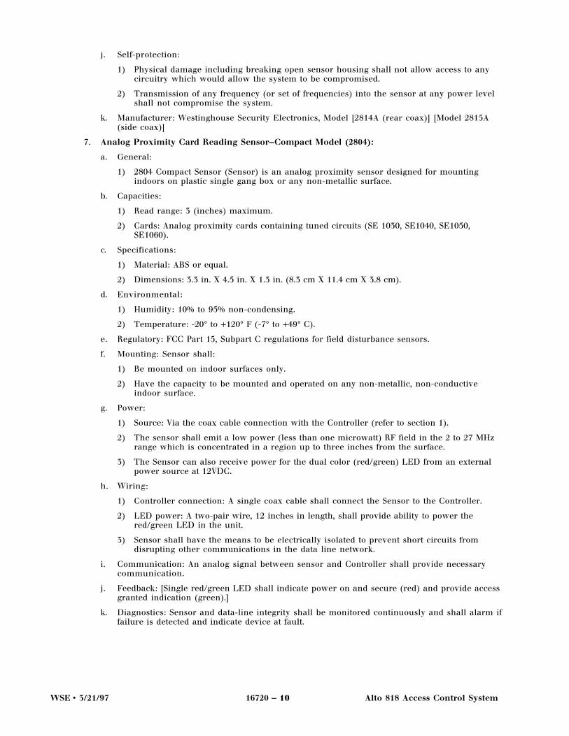
2. Multiple Switch Monitor (774A):
a. General:
1) The 774A Multiple Switch Monitor (MSM) is a single board monitor point input device[with enclosure] for connection to 4 dry contacts normally opened or normally closed.MSM supports higher voltages for extended read ranges.

WSE • 3/21/97 16720 — 6 Alto 818 Access Control System
b. Capacities:
1) Monitor point inputs: 4 (four) 2-state.
2) MSM units: up to 8
3) Monitor inputs: 32
c. Specifications:
1) MSM board dimensions: 4 in. Square by 1 in. (10 cm square X 2.54 cm).
2) [MSM enclosure dimensions: 4.5 in. square X 2.25 in. (12 cm X 15.7 cm).]
d. Environmental:
1) Humidity: 10% to 95% non-condensing.
2) Temperature: 20° to +120° F (-7° to +49° C).
e. Mounting: The MSM shall be mounted in a NEMA type enclosure with the Controller orstandalone in a controlled area.
f. Power:
1) Source: Coax wiring connected to the Controller.
g. Wiring:
1) A single coax cable with recommended maximum length of 1,000 feet shall connect theMSM to the Controller and must meet the following specifications:(i) Pure copper, single strand, 18 AWG center conductor, a foam dielectric and a dual
shield, 61% AL braid, 100% AL bond wrap, impedance of 75 ohms and the physicaldimensions of RG6/U. All spools must have a 100% sweep test before use.
(ii) Additional cables, for direct burial, plenum and elevator rated conforming to WSEmodels SE9284DB, SE9284PL and SE9284EL can be utilized for the respectiveapplications.
2) Input wiring: Twisted pair wiring with distances up to 200 feet between MSM and contactpoint.
3) Module shall require a supervisory End of Line resistor at each contact.
h. Communication: The MSM transmits information via the coaxial cable to the Controller.
i. Manufacturer: Westinghouse Security Electronics Model #774-A.
3. Annunciator Control Module (778A):
a. General:
1) 778A Remote Annunciator Module (Annunciator) provides 8 (eight) dry contact outputsplus status and latched alarm outputs.
2) Module shall also have building mode indicator and mode selector switch and inputpoints for remote selector switches.
3) Outputs are programmed to operate based on alarm/report generated from the Controller.
b. Capacities:
1) Output alarm contacts: 8 (eight).
2) Master latched alarm contact: 8 (eight).(i) Rating: 0.5A.
c. Specifications:
1) Dimensions: 12 in. X 5.25 in. X 3.375 in. (31 cm X 13.4 cm X 9.5 cm).
d. Environmental:
1) Humidity: 10% to 90% non-condensing.
2) Temperature: 20° to +120° F (-7° to +50° C).

WSE • 3/21/97 16720 — 7 Alto 818 Access Control System
e. Mounting: The Annunciator should be installed in a secure area within 12 feet of theController.
f. Power: Power provided by Controller.
g. Wiring: Included control cable.
h. Communication: Control signals for output relays and building mode switch are provided forthe Controller only.
i. Feedback:
1) Power ON: 1 (one) LED.
2) Output relay status: 8 (eight) LEDs.
3) Building mode status.
4) Mode selection switch status: Limited or Closed.
5) Latched alarm status.
j. Manufacturer: Westinghouse Security Electronics Model 778A Remote Annunciator Module.
4. Digital Proximity Key Reading Sensor (DigiReader):***********Note: There are currently five models of DigiReader digital proximity readers. Each reader providesdifferent read ranges. When compiling Specifications, use the “Read Range Matrix” (Part IV.1,Appendix) to determine the reader and card that best suit the specific application.***********
a. General:
1) DigiReader (DR) shall read digital proximity keys and send signal to Controller forprocessing.
2) DR 4226 shall comply with the Americans with Disability Act (ADA).
3) DR 4238 shall comply with the Americans with Disability Act (ADA).
b. Capacities:
1) DR shall read digital proximity keys supporting phase shift signals to a distance of [_____](optimum read range as defined in DigiReader/Prox Card Read Range Matrix) inches anddoes not require contact with the sensor
2) DR shall be capable of reading up to 3 (three) cards in field at the same time.
c. Specifications: Material shall be high-impact Lexan with 94V-2 UL flame class rating, andshall be UV resistant, sealed, water and weather resistant, and tamperproof.
d. Environmental:
1) Humidity: 10% to 90% non-condensing
2) Temperature: -4˚ to +140˚ F (-20˚ to +60 ˚ C).
e. Regulatory: Controller shall be designed to meet the following regulatory requirements:
1) UL294 Listing Standard for Safety.
2) FCC EMI and EMC Class A.
3) EN55022 EMI and EMC Class A.
f. Mounting:
1) DR shall have the capacity to be mounted and operated behind any non-metallic, non-conductive surface, including glass.
2) (DR 4204 only) DR shall have the capability to be mounted on any metal door frame.
g. Power:
1) Source: Via the network twisted pair (shielding optional) wiring.
2) Consumption:(i) [DR 4204: Less than 5 watts.]
(ii) [DR 4205: Less than 2 watts.]
(iii) [DR 4208: Less than 6.5 watts.]

WSE • 3/21/97 16720 — 8 Alto 818 Access Control System
(iv) DR 4226: Less than 17 watts.]
(v) DR 4238: Less than 17 watts.]
h. Wiring: Twisted pair (shielding optional) with 4,000 foot maximum recommended length.
i. Feedback:
1) Single tri-color LED (green/amber/red) shall provide capability for diagnostic feedback.
2) Tri-color LED shall be programmable.
3) An audio tone shall indicate successful digital proximity card read and access granted.
j. Diagnostics: DR and data-line integrity shall be monitored continuously and shall alarm iffailure is detected and indicate device and location of fault.
k. Self-protection:
1) Physical damage, including breaking open sensor housing, shall not allow access to anycircuitry which would allow the system to be compromised.
2) Transmission of any frequency (or set of frequencies) into the sensor at any power levelshall not compromise the system.
l. Manufacturer: Westinghouse Security Electronics
m. Model:
1) [Model DR 4204]
2) [Model DR 4205]
3) [Model DR 4208]
4) [Model DR 4226]
5) [Model DR 4238]
5. Keypad (VIP-2):
a. General:
1) The system shall have the means to utilize a numeric keypad for entry of a PersonalIdentification Number (PIN).
2) The Keypad shall provide information to the Controller, either alone or in conjunctionwith a card reading device, thereby providing an additional level of security.
3) The system shall have the means to recognize special duress codes which can be enteredinto the Keypad to be available to any user during an emergency.
4) System administrator shall have capability to program a reaction based on Keypad duresscode input.
b. Capacities:
1) Keypad shall provide a standard 10 digit numeric entries organized in the standardtelephone pad layout.
2) The user shall be able to enter either a 4- to 8-digit Personal Identification Number (PIN).
c. Specifications: The Keypad unit shall be housed in a double gang metal utility box, 4.50 in. Hx 4.56 in. W x 2.19 in. D (cm).
d. Environmental:
1) Temperature: 20˚ F to 120˚ F (-7˚ C to +49˚ C).
2) Humidity: 10% to 95% non-condensing.
e. Regulatory: The unit shall meet the following regulatory requirements:
1) FCC class A computing device when installed in the system.
2) ANSI/NEMA Standard 250 for Type 4x enclosures.
f. Mounting:
1) Keypad shall be mounted on the outside of a building, in a wall, or against it.

WSE • 3/21/97 16720 — 9 Alto 818 Access Control System
2) After the Keypad is installed and operations have been verified, decal shall be placed overthe cover plate to conceal mounting plate and to provide a weather seal.
g. Power: The Keypad receives power from the network twisted pair wiring.
h. Wiring: Twisted pair cable with a maximum recommended cable length of 4,000 feet.
i. Feedback: The Keypad shall provide three LED status for awaiting card presentation,awaiting keypad entry and acknowledgment of successful access granted and door unlock.
j. Self-protection: The Keypad is protected against the circuitry being removed from the outletbox or the box being forcibly removed from the wall by means of a strategically placedinternal tamper switch.
k. Manufacturer: Westinghouse Security Electronics Model: [VIP-2] [VIP-2W (weatherized)]
6. Analog Proximity Card Reading Sensor (SE 2800 Series):
a. General:
1) Analog Proximity Card Reading Sensor (Sensor) shall connect to the Controller via data-line as specified by the manufacturer.
2) Sensor shall have the means to be electrically isolated to prevent short circuits fromdisrupting other communications in the data-line network.
3) As a minimum, the Sensor shall detect command card codes when a card is within twoinches (5 cm) of it’s surface.
b. Capacities:
1) The Sensor shall “read in” data encoded on analog proximity cards containing tunedcircuits (Model SE 1050 or SE 1060) placed within a minimum of 2 inches of the sensor.
2) The Sensor shall not require contact with the sensor.
3) Specifications: The Sensor shall be sealed, waterproof, weather resistant, andtamperproof. Material shall be Lexan or equal.
c. Environmental:
1) Humidity: 0% to 100% condensing.
2) Temperature: -50° to +180° F (-46° to +82° C).
d. Mounting: Proximity Card Reading sensor shall have the capacity to be mounted andoperated behind any non-metallic, non-conductive surface, including glass.
e. Power:
1) Via the coax cable connection.
2) The Sensor shall emit a low power (less than one microwatt) RF field in the 2 to 27 MHzrange which is concentrated in a region up to 6 (six) inches from the surface.
f. Wiring: A single coax cable shall connect the Sensor to the Controller. Coax will conform tothe following:
1) A standard coax cable has a pure copper, single strand, 18 AWG center conductor, a foamdielectric and a dual shield, 61% AL braid, 100% AL bond wrap. This cable has animpedance of 75 ohms and the physical dimensions of RG6/U. All spools must have a100% sweep test before use.
2) Additional cables, for direct burial, plenum and elevator rated conforming to WSE modelsSE9284DB, SE9284PL and SE9284EL can be utilized for the respective applications.
g. Communication: An analog signal between sensor and Controller shall provide necessarycommunication.
h. Feedback: Single red LED shall indicate power on and provide capability for diagnosticfeedback.
i. Diagnostics:
1) Proximity Card Reading sensor and data-line integrity shall be monitored continuously.
2) An alarm shall sound if failure is detected and indicate device and location of fault.
WSE • 3/21/97 16720 — 10 Alto 818 Access Control System
j. Self-protection:
1) Physical damage including breaking open sensor housing shall not allow access to anycircuitry which would allow the system to be compromised.
2) Transmission of any frequency (or set of frequencies) into the sensor at any power levelshall not compromise the system.
k. Manufacturer: Westinghouse Security Electronics, Model [2814A (rear coax)] [Model 2815A(side coax)]
7. Analog Proximity Card Reading Sensor—Compact Model (2804):
a. General:
1) 2804 Compact Sensor (Sensor) is an analog proximity sensor designed for mountingindoors on plastic single gang box or any non-metallic surface.
b. Capacities:
1) Read range: 3 (inches) maximum.
2) Cards: Analog proximity cards containing tuned circuits (SE 1030, SE1040, SE1050,SE1060).
c. Specifications:
1) Material: ABS or equal.
2) Dimensions: 3.3 in. X 4.5 in. X 1.3 in. (8.3 cm X 11.4 cm X 3.8 cm).
d. Environmental:
1) Humidity: 10% to 95% non-condensing.
2) Temperature: -20° to +120° F (-7° to +49° C).
e. Regulatory: FCC Part 15, Subpart C regulations for field disturbance sensors.
f. Mounting: Sensor shall:
1) Be mounted on indoor surfaces only.
2) Have the capacity to be mounted and operated on any non-metallic, non-conductiveindoor surface.
g. Power:
1) Source: Via the coax cable connection with the Controller (refer to section 1).
2) The sensor shall emit a low power (less than one microwatt) RF field in the 2 to 27 MHzrange which is concentrated in a region up to three inches from the surface.
3) The Sensor can also receive power for the dual color (red/green) LED from an externalpower source at 12VDC.
h. Wiring:
1) Controller connection: A single coax cable shall connect the Sensor to the Controller.
2) LED power: A two-pair wire, 12 inches in length, shall provide ability to power thered/green LED in the unit.
3) Sensor shall have the means to be electrically isolated to prevent short circuits fromdisrupting other communications in the data line network.
i. Communication: An analog signal between sensor and Controller shall provide necessarycommunication.
j. Feedback: [Single red/green LED shall indicate power on and secure (red) and provide accessgranted indication (green).]
k. Diagnostics: Sensor and data-line integrity shall be monitored continuously and shall alarm iffailure is detected and indicate device at fault.

WSE • 3/21/97 16720 — 11 Alto 818 Access Control System
l. Self-protection:
1) Physical damage including breaking open sensor housing shall not allow access to anycircuitry which would allow the system to be compromised.
2) Transmission of any frequency (or set of frequencies) into the sensor at any power levelshall not compromise the system.
m. Manufacturer: Westinghouse Security Electronics, Model:
1) [2804-B (black)].
2) [2804-G (gray)].
8. QuadraKey Digital Proximity Command Card:
a. General:
1) QuadraKey Digital Proximity Command Key (Card) is an ISO compliant, single-coilpassive proximity card that supports multiple technologies on one card, including:proximity, magnetic stripe, bar code and photo ID.
2) Design shall be capable of smart card chip insertion, color imaging on both sides andhole punch horizontal or vertical for using the card as a badge.
3) Each card shall have the capability to be programmed to operate universally at differentlocations.
4) Note: Active circuit type cards (those requiring batteries) shall not be acceptable.
b. Capacities:
1) Card can generate a minimum eight digit access number.
2) Cards shall have numeric encoded data. embedded in an integrated circuit within thecard.
3) Each card shall be encoded so that it is totally unique and is not duplicated anywhere inthe world.
c. Specifications:
1) Dimensions: ISO standard size and thickness of 3.37 in. X 2.125 in. X 0.032 in (8.55 cm X5.39 cm X 0.081 cm).
2) Material: Polyester and appropriate adhesive based materials.
3) Magnetic Stripe material: single layer 3M type 5203 High Coercivity, 4000 Oerstad usingTrack 2, without exception.
4) Magnetic stripe dimensions: The stripe shall minimally extend from 0.333 in. to 0.493 in.from the upper card edge and for the entire length of the card.
d. Environmental:
1) Temperature: 14° to 140° F(-10° to 60° C).
2) Humidity: 0% to 100%.
e. Regulatory: N/A (Card is totally passive requiring no approval.)
f. Power:
1) Source: Passive-powered by DigiReader digital proximity reader.
2) Consumption: Not detectable.
g. Communication: Via low power radio frequency, providing read ranges up to [22] inchesdepending on the selected DigiReader. (See DigiReader/Prox Card Read Range Matrix in PartIV.1 for actual figures).
h. Manufacturer: Westinghouse Security Electronics, Model QuadraKey.
9. NexKey Digital Proximity Command Card:
a. General:
1) NexKey Digital Proximity Command Key (Card) is a single-coil passive proximity cardthat can, through add-on options, support additional technologies, including: bar codeand photo ID with lamination.

WSE • 3/21/97 16720 — 12 Alto 818 Access Control System
2) Each card shall be encoded so that it is totally unique and is not duplicated anywhere inthe world.
3) Card shall be highly resistant to face abrasion or bending.
4) Card shall have a slot in the vertical position for use as a badge.
5) Note : Active circuit type cards (those requiring batteries) shall not be acceptable.
b. Capacities:
1) Card can generate a minimum eight digit access number.
2) Cards shall have numeric encoded data embedded in an integrated circuit within thecard.
3) Each card shall be encoded so that it is totally unique and exists in no other systemanywhere in the world.
c. Specifications:
1) Dimensions: 3.37 X 2.125 X 0.075 in. (8.55 X 5.93 X 0.19 cm)
2) Construction: Durable ABS with vinyl or polycarbonate covering.
d. Environmental:
1) Temperature: 14° to 140° F (-10° to 60° C)
2) Humidity 0% to 100% humidity.
e. Regulatory: N/A (Card is totally passive requiring no approval.)
f. Power: Passive-powered by DigiReader digital proximity reader.
g. Communication: Card shall communicate via low power radio frequency, providing readranges up to [22] inches depending on the selected DigiReader. (See DigiReader/Prox Cardread range matrix for actual figures).
h. Manufacturer: Westinghouse Security Electronics, Model: NexKey.
10. DuraKey Digital Proximity Command Card:
a. General:
1) DuraKey Digital Proximity Command Key (Card) is a highly durable, dual-coil passiveproximity card that supports multiple card technologies on one card, including:proximity, bar code, and photo ID with lamination.
2) Each card shall be encoded so that it is totally unique and is not duplicated anywhere inthe world.
3) Note : Active circuit type cards (those requiring batteries) shall not be acceptable.
b. Capacities:
1) Card can generate a minimum eight digit access number.
2) Cards shall have numeric encoded data embedded in an integrated circuit within thecard. Each card shall be encoded so that it is totally unique and exists in no other systemanywhere in the world.
c. Specifications:
1) Dimensions: 3.37 X 2.125 X 0.099 in. (8.55 X 5.93 X 0.25 cm).
2) Construction: Durable polycarbonate with vinyl covering.
d. Environmental:
1) Temperature: 14° to 140° F (-10° to 60° C).
2) Humidity: 0% to 100% relative humidity.

WSE • 3/21/97 16720 — 13 Alto 818 Access Control System
e. Regulatory: N/A (Card is totally passive requiring no approval).
f. Power: Passive-powered by DigiReader digital proximity reader.
g. Communication: Card shall communicate via low power radio frequency, providing readranges up to [36] inches depending on the selected DigiReader. (See DigiReader/Prox Cardread range matrix for actual figures)
h. Manufacturer: Westinghouse Security Electronics, Model: DuraKey.
11. Analog Proximity Command Card ([SE 1050] [SE1060]):
a. General: [SE 1050] [SE1060] is a highly durable analog proximity command key (Card) thattransfers data in the form of passive tuned circuits within the card. Additional card featuresinclude:
1) Unique encoding: Each card shall be encoded so that it is totally unique.
2) Universal operation: Each card shall have the capability to be programmed to operateuniversally at different locations.
3) Durable: Card shall be highly resistant to face abrasion or bending.
4) Warranty: 5 (five) years.
5) Note: Active circuit type cards (those requiring batteries) shall not be acceptable.
b. Capacities: Card can generate an eight digit access number.
c. Specifications:
1) Dimensions: 3.36 X 2.12 X 0.1 in. (8.53 X 5.38 X 0.25 cm).
2) Construction: Heavy duty fiberglass epoxy with vinyl covering.
d. Environmental:
1) Temperature: -50° to +120° F (-46° to 49° C).
2) Humidity: 0% to 100% relative humidity.
e. Regulatory: N/A (Card is totally passive requiring no approval).
f. Power: Passive-powered by Analog Proximity Card Sensor.
g. Communication: Via field disturbance from Analog Proximity Card Sensor.
h. Manufacturer: Westinghouse Security Electronics, Model: [SE 1050 Command Key] [SE 1060Command Key
12. Power Supply, Controller (3018):
a. General: The Power Supply can provide continuous power to the Controller, sensors, monitormodules and annunciator devices.
b. Capacities: The Power Supply shall provide low volt DC output to the Controller.
c. Specifications:
1) Dimensions: 7 in. X 5.7 in. X 3.125 in. depth (17.8 cm L X 14.5 cm W X 7.9 cm D).
d. Environmental:
1) Humidity: 10% to 95% non-condensing.
2) Temperature: 20° to +120° F (-7° to +49° C).
e. Regulatory: UL 1012 or 1310 and CSA or cUL listed. [ Option 230VAC/50Hz is not UL, CSA orcUL listed.]
f. Mounting: The Controller Power Supply should be installed in a secure area at least 2 feetaway.
g. Power: 115VAC/60Hz source. [Option: 230VAC/50Hz.]
h. Wiring:
1) The power supply shall be connected to the Controller via wiring of at least 18 AWG.
2) Connectors: Phoenix.

WSE • 3/21/97 16720 — 14 Alto 818 Access Control System
i. Feedback: A single LED indicates power ON condition.
j. Manufacturer: Westinghouse Security Electronics Model 3018, or other Westinghouseapproved device.
13. Power Supply with battery backup, Controller (3718S or 718SUL):
a. General:
1) Un-interruptable Power Supply shall provide continuous power to the Controller,sensors, monitor modules and annunciator devices and operate from 115VAC/60Hz[Option: 230VAC/50Hz] source.
2) Optionally, it shall support external lead acid battery(s) to maintain all Controller, sensorand monitor modules operations for at least 4 (four) hours in event of power failure.
b. Capacities: The Power supply shall provide:
1) Low volt DC output to the Controller.
2) Limited lock power output at 12 [or 24] Volts DC.
3) 5 ampere output current at 12 VDC, 1.5 A at 24 VDC.
4) Power failure output and battery charger output.
c. Specifications:
1) Dimensions: 18 in. X 7.2 in. X 5.2 in. depth (45.7 cm X 18.3 cm X 13.2 cm).
d. Environmental:
1) Humidity: 10% to 95% non-condensing.
2) Temperature: 20° to +120° F (-7° to +49° C).
e. Regulatory: UL 1012 or 1310 and CSA or cUL listed. [Option 230VAC/50Hz is not UL listed.]
f. Mounting: The Power Supply should be installed in a secure area at least two feet from theController.
g. Power: 115VAC/60Hz source. [Option: 230VAC/50Hz.]
h. Wiring:
1) The power supply shall be connected to the Controller via a special wiring harness of atleast 18 AWG.
2) The power supply shall utilize phoenix type connectors to allow for ease of field wiringand unit replacement.
i. Feedback: A single LED indicates power ON condition.
j. Self-protection: The power supply shall provide the following signals to the Controller:
1) Power fail.
2) Battery recharge signal.
k. Manufacturer: Westinghouse Security Electronics Model 3718S [3718SUL] or otherWestinghouse approved device.
14. Power Supply (PI-1):
a. General: Un-interruptable Power Source Module shall provide low voltage DC power. It shallalso support optional external lead acid batteries to maintain all controller operations for atleast four (4) hours in event of power failure.
b. Capacities:
1) 28 volt DC output to readers.
2) Limited lock power output at 24 Volts DC.
3) 5 ampere output current.
4) Power failure output.
5) Battery charger output.
6) Additional Power Supplies may be required based upon system configuration of otherdevices and wiring distances.

WSE • 3/21/97 16720 — 15 Alto 818 Access Control System
c. Specifications:
1) Dimensions: 12 in. X 5.25 in. X 3.375 in. (31 cm X 13.4 cm X 9.5 cm)
d. Environmental:
1) Humidity: 10% to 90% non-condensing
2) Temperature: 20˚ to +120˚ F (-7˚ to +49˚ C).
e. Regulatory: UL 1012 or 1310 and CSA or cUL listed.
1) NOTE: The Power Inserter is required when configuring NexSentry with a Keypadand/or Digital Readers in order to meet FCC requirements.
f. Mounting: The Power Supply should be installed in a secure area at least two feet from theController.
g. Power: 115VAC/60Hz source.
h. Wiring:
1) The power supply shall be connected to the Controller and keypad network wiring viatwisted pair wire (shielding optional) of at least 18 AWG.
2) Connectors: Phoenix-type.
i. Feedback: A single LED indicates power ON condition.
j. Self-protection: PI-1 shall send a POWER FAIL signal to the controller.
k. Manufacturer: Westinghouse Security Electronics Model PI-1, or other manufacturer-approved device.
15. Accessories
a. Terminal:
1) Standard Video display terminal (CRT) with full keyboard and display.
2) Shall be capable of data throughput at 9600 baud.
3) Systems Integrator shall furnish as shown on plans.
4) Manufacturer: Westinghouse Security Electronics; Model #57101-L-1 (110v) / 57101-L-2(230v) or equal.
b. Printer:
1) Printer shall be standard RS-232 serial communications printer.
2) Printer shall be capable of data throughput at 9600 baud.
3) Systems Integrator shall furnish as shown on plans.
4) Manufacturer: Westinghouse Security Electronics; Model parallel/serial 57184-V (115v) /57184-V (230v) or equal.
c. Locking Hardware:
1) Systems Integrator shall furnish all system electrified locking hardware as shown onplans which is used in conjunction with Card Access & Alarm Monitoring system.
d. Switches:
1) Provide all necessary monitoring and manual switches as shown on plans which areused in conjunction with Card Access Security System.
e. External UPS batteries:
1) Provide necessary batteries to be used with UPS power supply to maintain all controlleroperations and provide limited DC lock power at either 12VDC or 24VDC.

WSE • 3/21/97 16720 — 16 Alto 818 Access Control System
C. Controller software features:
1. Control operation: Based on the ability to force relay lock outputs to an operating mode. Forcingaction may be initiated by:
a. Time of Day schedule.
b. Switch Closure.
c. Command Card Presentation.
d. Keyboard Command.
2. Access Codes:
a. The access code shall define where and when the card holder will be granted access.
b. Number available: 120.
c. Capacity: Each access code shall have the capacity of defining up to 4 (four) time periods foreach door in the system.
d. Definable time periods: Time of Day, Day of Week, and Holidays.
3. Holidays:
a. User definable holidays: up to 30.
b. By way of the Access command the user may define the access privileges (times and doors) ofa card holder for any or all of those days.#
4. Card Commands: The user shall be able to define command cards according to the followingparameters:
a. Unique numeric identification: 11,200 command cards.
b. 12 character description and unique numeric identification: 4,400 command cards.
c. Both cards with names and without within the same data-base.
d. Bulk program cards in groups and remove any card from the database.
e. Any card usage shall be traced by the system and a card trace report generated.
5. Card functions: Card functions shall include:
a. Access:
1) Access parameter definition: any single card can be programmed to open each doorduring four different time periods.
2) Time intervals: Up to 128 different time intervals.
3) Modification of card access parameters: may be modified at any time.
b. Building Mode:
1) Any card shall have means to be programmed as PRIVILEGED and be authorized to armor disarm the building mode feature.
2) If the card is not authorized to disarm mode alarm system, the card user shall be unablegain entry, regardless if user’s Access Code has been programmed for that period.
3) Building Modes shall be defined as follows:(i) OPEN mode: designates any key holder, privileged or not, may enter the building
provided he has a valid access code (used during peak normal hours).
(ii) LIMIT mode: designates when a privileged key holder may enter the building,provided he has a valid access code.
(iii) CLOSED mode: is used when the building is unoccupied. Although a privileged keyholder may enter a closed building, he must put the structure in the open or limitedmode within one minute or an alarm will be activated.
c. Anti-passback:
1) System shall have capability to designate any command card so that when it is used toenter an area it must be used to exit that area before it can be reused for entry.
2) System shall have capability to manually or automatically reset the location of allcommand card’s passback status at any time.

WSE • 3/21/97 16720 — 17 Alto 818 Access Control System
3) Anti-passback modes:(i) HARD mode: Denies re-entry and reports passback violation.
(ii) SOFT mode: Allows re-entry but reports passback violation.
6. Monitoring (if monitoring module is required):
a. Supervised alarm contacts: up to 32.
b. Character names: up to 24 characters defined by user.
c. Monitor points shall:
1) Be designated by the user as an alarm or non alarm event.
2) Be elected to either monitor at all times or during selected time periods.
3) Be capable of being enabled/disabled from terminal or externally from card holder.
4) Be capable of enabling any lock output or annunciator output including latched alarmcontact.
5) Work with the controller to provide immediate re-lock after card holder has gainedaccess into a facility. Systems re-locking only after preset time delay shall not beacceptable.
7. Annunciation (if Annunciator is used):
a. Annunciation may be sent to unused controller lock outputs or to remote annunciationmodule.
b. System shall have means to annunciate any alarm report generated by the system including:
1) All monitor points.
2) Power fail input.
3) Tamper input.
4) Card trace reports.
5) Access denied reports.
6) Passback violations, etc.
8. Alarm Shunting:
a. System shall have means to connect presence detecting device to shunt alarms whenauthorized employee uses an alarmed exit.
b. Exit reporting shall be selectable by user.
9. Forced Entry Alarms:
a. System shall have means to select which doors shall report forced entry alarms or door heldopen alarms.
b. On a door by door basis, user shall be able to select which doors are to report forced entryand during what time periods.
c. User shall be able to select whether such alarms will be generated at all times or whensystem is in “night” mode.
10. Passwords:
a. Identification of operators for terminal use: 8 (eight) different operators.
b. User definable passwords: Up to 12 (twelve) character user definable passwords shall be usedto log on to the system.
c. Access levels: Up to 6 (six) access levels each having different operator function capabilitiesshall be available.

WSE • 3/21/97 16720 — 18 Alto 818 Access Control System
11. Printed Data Output: System shall be capable of selecting which access and monitor pointactivity messages are to be output the printer. The system shall be capable of printing thefollowing information:
a. Card Definitions: Keycodes/ Names/ Access Codes/Location (In-Out status for anti-passback)/Key trace function (Enable/Disable)/ whether Privileged or not.
b. Monitored Point Parameters.
c. Door Parameters.
d. Access Code Parameters.
e. User Names, Passwords, and Access Levels.
f. System Status (real time report).
g. All Report Types.
12. Sensors:
a. System shall be able to assign a 24 character name for each sensor.
b. System shall be capable of defining which sensors and at what times they are to report validaccess reports.
c. User shall be able to select which times and at what sensors key trace reports are generated.
d. User shall be able to define which are “night mode” sensors (sensors where privileged cardsfunction).
13. Dial-up:
a. System shall capable of utilizing a dial-up modem to automatically report alarms or sendmessages to a central station or remote terminal.
b. There shall be at least 3 telephone numbers programmable for dial-up use.
c. User shall be able to define how many attempts (up to 10) will be made to communicate viadial-up.
14. Telecommunications:
a. System shall be capable of being programmed remotely via modem.
b. System shall have means to be programmed so that it requires central station to “call back”controller to ensure that only central station can gain access to controller database.
PART III EXECUTION
.1 EQUIPMENT INSTALLATION AND DOCUMENTATION
A. Installation:
1. The Proximity Access Control and Alarm Monitoring System shall be installed and wiredcompletely as shown on the plans by a trained and authorized Westinghouse Security ElectronicsSystems Integrator.
2. Systems Integrator shall make all necessary wiring connections to external devices andequipment.
B. Telephone Lines:
1. The owner shall arrange for dedicated or dial-up telephone lines for the telecommunicationsequipment as shown on the plans.
2. Each phone line shall be terminated in an RJ-11 telephone jack.
3. Note: Any connections to the public telephone system require notification of the localtelephone company. See Specific instructions in manual for modem used.

WSE • 3/21/97 16720 — 19 Alto 818 Access Control System
C. Documentation:
1. Accurate “as built” drawings shall be furnished by the Systems Integrator to aid the owner inprogramming. These should indicate the door(s) controlled by each lock output, the monitoringpoints for the door controlled area, and any annunciator outputs or special inputs into the system.
2. The Systems Integrator shall supply operating and maintenance manuals to aid the owner in theprogramming of the system.
.2 SERVICE AND SUPPORT
A. Startup:
1. After the system has been installed, the documentation delivered to the owner and the telephonelines are operational in compliance with Part III.1 above, the Systems Integrator shall verifycorrect operation of all system components.
2. The Systems Integrator shall guarantee all material and workmanship involving the system forup to [_____] year after startup.
B. Training:
1. After system startup, the Systems Integrator shall instruct owners personnel in how to programthe system and demonstrate a typical operating program for a single door controlled area.
C. Warranty Support:
1. The Authorized Systems Integrator shall be available during the warranty period to answerprogramming and application questions to support owners personnel during this period.
2. [Option: The Authorized Systems Integrator shall have capability to have a remote terminal forprogramming the Access Controller to support the owner’s personnel during this period. Theowners system shall include a modem SE Model # 5200 or equal, necessary cabling andtelephone extension to support this telecommunications operation.]
3. [Option: The Authorized Systems Integrator shall have the training and capability to provideadditional support services including:
a. Regular testing and inspection of all system components and to submit reports on the results.
b. Emergency Service for repairs and adjustments to the system and part replacement ifnecessary.]


WSE • 3/21/97 16720 — A Alto 818 Access Control System
PART IV APPENDIX
.1 READ RANGE MATRIX
DigiReader® Digital Proximity Reader
Prox Card DR4204 DR4205 DR4208 DR4226 DR4238
QuadraKey up to 2"(5.08 cm)
up to 4"(10.16 cm)
up to 7"(17.78 cm)
up to 13"(33.02 cm)
up to 22"(55.88 cm)
NexKey up to 2"(5.08 cm)
up to 4"(10.16 cm)
up to 7"(17.78 cm)
up to 13"(33.02 cm)
up to 22"(55.88 cm)
DuraKey up to 3"(7.62 cm)
up to 6"(15.24 cm)
up to 8"(20.32 cm)
up to 22"(55.88 cm)
up to 36"(91.44 cm)
Maximum read ranges may vary depending on physical environment of installation
.2 MOUNTING DIAGRAMS
A. Alto 818SX/Alto 818SC:
CH
AS
GN
D16
VA
CG
ND
/CT
16V
AC
25.2
VA
C25
.2V
AC
AN
TI-
TA
MP
ER
PO
WE
R F
AIL
CO
MM
ON
1,2
LOC
K 1
LOC
K 2
CO
MM
ON
3,4
LOC
K 3
LOC
K 4
CO
MM
ON
5,6
LOC
K 5
LOC
K 6
CO
MM
ON
7,8
LOC
K 7
LOC
K 8
TX
-T
X +
RX
-R
X +
CH
AS
GN
DR
LSD
GN
DD
CE
RC
TS
RT
SR
DT
DD
TE
R
DT
ER
TDRD
RT
SC
TS
DC
ER
GN
DR
LSD
CH
AS
GN
D
MP
-M
P +
SH
IELD
RE
TU
RN
PW
RG
ND
B A
SENSOR 1
SENSOR 2
SENSOR 3
SENSOR 4
SENSOR 5
SENSOR 6
SENSOR 7
SENSOR 8
POWER RELAYS 20mA HOST TERMINAL ANNUNCIATOR RS485
MADE IN U.S.A.
SEE INSIDE COVER FOR WIRING INSTRUCTIONS
VITALFUNCTION
1
5 6
2 3
7
4
8
RX RX
TX TX
RELAYS HOST TERMINAL
7.40
17.20
18.0
10.4
ALTO 818SX
Model No. 818SX
2.2
WSE • 3/21/97 16720 — B Alto 818 Access Control System
B. Multiple Switch Monitor (774-A):
Terminal Resistance 36 ohms
L H L H L H L H
1 2 3 4
COAX COAX
WITHOUTSENSOR
2814281528CS
2854/55
MULTIPLE SWITCH MONITORMODEL 774-A
MADE IN U.S.A.
36K 36K
36K 36K

WSE • 3/21/97 16720 — C Alto 818 Access Control System
C. 778 Annunciator Control Module (Annunciator):
NIGHTNORMALFN
12 in(31 cm)
12 in (31 cm)

WSE • 3/21/97 16720 — D Alto 818 Access Control System
.3 SAMPLE SYSTEM DIAGRAMS
A. Alto 818 SC Digital Proximity with Keypad:
Twisted pair wire
LEGEND
RS-232
Phone line
Video switcher
Remote security centeror alarm central station
778 Annunciator
Videomonitor
3708S Power module
AC input
Modem
Modem
Printer
Publicphonesystem
up to
eig
ht d
oors
per
Alto
818
SC A
CU
Parking lot Main entrance Manufacturing Cafeteria
CCTVcamera
CCTVcamera
CCTVcamera
Lock Lock
DigiReader(DR 4238)
DigiReader Keypad Keypad
MSM
INSensor loop
MSM
Door switch
Motion sensor (REX)
Glass breakdetector
Fire sensor
MSM
Alarm Alarm Alarm
OUTSensor loop
DigiReader DigiReader
Gate arm
SE 5850 orSE 6000 host
Coax
15-pin ribbon
RS-485
Door switch
Motion sensor (REX)
Glass breakdetector
Fire sensor

WSE • 3/21/97 16720 — E Alto 818 Access Control System
B. Alto 818SX Analog Proximity with Keypad:
Videomonitor
Video switcher
Remote security centeror alarm central station
778 Annunciator
3718SUL Power module
Battery
AC input
Modem
Modem
Printer
Publicphonesystem
Parking lot Main entrance Manufacturing Copy center
CCTVcamera
CCTVcamera
CCTVcamera
KeypadKeypad
MSM MSM MSM MSM
Gate arm
SE 2814sensor
SE 2814sensor
SE 2814sensor
SE 2814sensor
Twisted pair wire
LEGEND
RS-232
Phone line
Coax
15-pin ribbon
Host
INSensor loop
Door switch
Motion sensor (REX)
Glass breakdetector
Fire sensor
OUTSensor loop
Door switch
Motion sensor (REX)
Glass breakdetector
Fire sensor
Alarm Alarm Alarm
Lock Lock
up to
eig
ht d
oors
per
Alto
818
SX A
CU