alu prop - the formwork
TRANSCRIPT
ALU PROP
ALU PROP

CARATTERISTICHE
COMPONENTI SISTEMA
ACCESSORI
CARATTERISTICHE TECNICHE
DEGLI ELEMENTI
ISTRUZIONI DI MONTAGGIO
ASSEMBLAGGIO ORIZZONTALE
ASSEMBLAGGIO VERTICALE
CONTROVENTATURE
TRASPORTO E STOCCAGGIO
LISTA COMPONENTI
FEATURES
SYSTEM COMPONENTS
ACCESSORIES
ELEMENTS TECHNICAL
FEATURES
ASSEMBLING INSTRUCTION
HORIZONTAL ASSEMBLY
VERTICAL ASSEMBLY
TUBE & COUPLERS BRACING
TRANSPORT & STORAGE
ITEMS LIST
5
6
7
8
14
16
18
20
20
21
5
6
7
8
14
16
18
20
20
21
S U M M A R Y S O M M A R I O
SAFETY WARNINGS
• The respect of these instructions does not exempt from compliance with all safety regulations in force in the country where you use the system.
• These instructions are intended for users of TF products and systems. Each one must be aware of the contents of this manual; in case they have difficulties in reading the same, the employer has to provide education of the same
• The User’s Manual instructions must always be available at the workplace for all operators
• This manual, even if used in order to draw up a Method Statement, will not substitute it, and the Method Statement will remain an important and unavoidable site document, responsibility of the client.
• Information and illustrations contained herein are relative to only the system in question, and therefore not exhaustive about the overall security; always refer to the applicable health and safety regulations in the area of use of the equipment
• In relation to flow, configuration, installation, use and dismantling of equipment TF Strictly obey all instructions contained herein; failure to comply with them may result in serious accidents to people, as well as extensive property damage
• Take every precaution consequently due to the climatic conditions of the site (i.e. in case of rain and/or ice to provide anti-slip measures etc.)
• Periodically verify, especially after severe weather conditions, any connection, wedge or any other connecting element, in order to avoid any possible system instability and consequent accidents
AVVERTENZE SULLA SICUREZZA
• Il rispetto delle presenti istruzioni non esime dall’osservanza di tutte le norme sulla sicurezza vigenti nel paese dove si utilizzi il Sistema in oggetto
• Le istruzioni qui riportate sono rivolte agli utilizzatori di prodotti e siste-mi The Formwork. Ognuno di essi deve essere a conoscenza del con-tenuto di questo manuale; in caso abbiano difficoltà nella lettura dello stesso, il datore di lavoro deve provvedere all’istruzione degli stessi
• Le istruzioni d’uso devono sempre essere disponibili sul luogo di lavoro per tutti gli operatori
• Il presente manuale, pur potendo essere utilizzato per la redazione di un piano operativo utilizzandone le informazioni utili, non lo sostituisce, ed il piano resta comunque obbligo del cliente ed in capo al datore di lavoro degli operatori.
• Informazioni ed illustrazioni qui contenute sono relative al solo sistema in oggetto, e quindi non esaustive riguardo la sicurezza generale; fare sempre riferimento alle norme vigenti per la si-curezza sul territorio di utilizzo delle attrezzature
• Rispettare scrupolosamente ogni indicazioni qui contenuta rela-tivamente a portate, configurazioni, montaggio, uso e smontag-gio delle attrezzature TF; la mancata osservanza delle stesse può essere causa di incidenti gravi per le persone, nonchè di gravi danni alle cose.
• Adottare ogni dovuta precauzione conseguentemente alle condizioni climatiche di cantiere (p.e. in caso di pioggia e/o ghiaccio prevedere misure anti-scivolo etc..)
• Controllare sempre, ed in special modo dopo eventi climatici particolari, ogni giunzione, cuneo o qualsivoglia elemento di fissaggio/collegamento, onde prevenire possibili instabilità del sistema e conseguenti incidenti

5
STANDARD MODULARITY: system modularity is given by Connecting Frames sizes in the ”horizontal”, and they will be defined following the requested loadability. Concerning the “vertical” modularity, it’s handled by the Alu Prop gamma other than the possibility to join the props by end flanges connection reaching in this way the needed heights.
HIGH WORK LOADS: the heavy duty Alu Props, combined with Connecting Frames positioning, guarantee the adaptation the system loadability to the loads coming from the structures to be supported. No fix loadability dats are showed given the wide variability permitted by Alu Props and Connecting Frames combination.
EASY TO USE: composed by Connecting Frames, Alu Props and very few accessories, the system result very easy to use and consequentely safe in both erection and dismantling phases.
EASY SHIFTING: dedicated devices, TF heavy duty wheels, TF lifting fork and straps offer a safe and fast solution for the most efficient and safe shifting planning.
SAFETY: the system loadability, stability and modularity are already a guarantee of safety, increased by a specific assembling and operative method of statement, wich is easily done using the instructions herein illustrated.
TF Alu Towers is the ideal solution in order to realize in situ heavy slabs at relevant heights, offering the necessary loadability and a working area at height by Aluminium Heavy Duty Props and system components as Connecting Frames wich stabilize the towers and increasing the loadability.
FEATURES
MODULARITA’ STANDARD: la modularità del Sistema “in pianta” è dettata dai formati dei Telai di collegamento; gli stessi vengono definiti in base alle portate richieste, oltre che alle geometrie delle strutture in progetto. Riguardo la modularità “verticale”, la stessa viene gestita dalla gamma dei Puntelli in Alluminio oltre che dalla possibilità di sovrapporre gli stessi mediante il collegamento delle flange di testa/piede per raggiungere le altezze richieste.
ELEVATI CARICHI DI ESERCIZIO: l’alta portata dei Puntelli in Alluminio, sommata al posizionamento dei Telai di collegamento, garantisce il poter adeguare la portata del Sistema ai carichi delle strutture in realizzazione. Non si indicano valori precisi al riguardo, proprio per la grande variabilità permessa dalla combinazione di Puntelli e Telai.
SEMPLICITA’ D’USO: composto da telai di collegamento, Puntelli in alluminio e pochi accessori di collegamento, il sistema risulta molto semplice nell’uso e quindi sicuro sia in fase di armo che di disarmo.
FACILITA’ DI TRASLAZIONE: accessori dedicati,come le ruote ad alta portata TF 2, la forca di sollevamento TF e le cinghie di sollevamento garantiscono una soluzione veloce e sicura per la più efficiente pianificazione dei cicli di lavoro.
SICUREZZA: la portata del Sistema, nonchè la stabilità e modularità sono già sinonimo di sicurezza, incre- mentata da uno specifico piano operativo di assem- blaggio ed utilizzo, la cui redazione è facilitata dalle istruzioni qui riportate.
TF Alu Towers è la soluzione ideale per la realizzazione di solai in opera con carichi elevati ed altezze rilevanti, garantendo la necessaria portata ed il raggiungimento della quota di lavoro attraverso I Puntelli in Alluminio ad alta portata ed I componenti di sistema quali I Telai di collegamento che stabilizzano le torri oltre ad aumentarne la portata.
CARATTERISTICHE
ALU PROP | ALU PROP

6 7
ALU PROP | ALU PROP
ACCESSORIES | ACCESSORI
3. ALU PROP EXTENSIONS
PROLUNGHE PUNTELLI ALU PROP
Outer Tube | Tubo esterno
End plates | Flange di testa
4. ALU PROP TRIPOD
TREPPIEDE ALU PROP
6. ALU PROP CONNECTING BOLT
BULLONE DI FISSAGGIO ALU PROP Bolt M 12 Bullone M 12 Nut M 12 Dado M 12
5. ALU PROP WALING CONNECTOR
CONNETTORE CORRENTI ALU PROP Fixing Hook Gancio di fissaggio Connecting plate Piastra di collegamento Threaded rod M 16 Barra filettata M 16 Nut M 16 Dado M 16
A
AA
A
A
AB
B
B B
B
B
C
D
D
C
7. ALU PROP CLAMP & COUPLER
MORSETTO & GIUNTO ALU PROP
SYSTEM COMPONENTS | COMPONENTI SISTEMA
1. ALUMINIUM PROPS
PUNTELLI IN ALLUMINIO
Outer Tube | Tubo esterno
Inner Tube | Tubo interno
Safety Hook | Gancio di sicurezza
Adjusting Nut | Ghiera di regolazione
Bearing Plate | Flangia portante
Foot plate | Flangia di base
Head Plate | Flangia di testa
2. ALU PROP CONNECTING FRAMES
TELAI DI COLLEGAMENTO ALU PROP
Wedge Connection | Morsetto a cuneo
Wedge | Cuneo
G
B
A
A
A
B
B
CDEFG
F
B
B
D
E C
A
A

8 9
ALU PROP | ALU PROP
ALU PROP CONNECRTING FRAMES | TELAI DI COLLEGAMENTO ALU PROP
EXTENSIONS P 105 | PROLUNGHE P 105
ART.Height
mmLenght
mmWeight
Kg
TL500105SZ 500 500 6,5
TL1000105SZ 500 1000 9,3
TL1250105SZ 500 1250 10,5
TL1500105SZ 500 1500 11,5
TL2000105SZ 500 2000 14,0
TL2500105SZ 500 2500 15,7
ART.Height
mmWeight
Kg
P500105V 500 3,5
P1000105V 1000 5,7
P1500105V 1500 8,0
P2000105V 2000 10,2
P3000105V 3000 14,8
Extension can be used as a Prop extension to make it longer when needed, or as a link between 2 base plates of 2 props ( with 4 bolts M 12 x 40 in diagonal ) to extend the tower working height.
Le prolunghe possono essere utilizzate come “allun-gamento” del singolo puntello, oppure fra 2 flange di collegamento dei puntelli (con 4 bulloni M 12 x 40 in diagonale) per estendere l’altezza di lavoro nella con-figurazione a Torre Alu Prop.
Made with the same aluminium structure and features as the Props.
Realizzate con la stessa struttura in alluminio e carat-teristiche dei Puntelli Alu Prop.
ALUMINIUM PROPS TF P 105 / TF P 70 | PUNTELLI IN ALLUMINIO TF P 105 / TF P 70
P 105 is the TF Aluminium Prop for slabs, to be used in stan-dard configuration or coupled with Alu Prop Connecting Frames to shift to a tower systems when convenient. It guarantee the maximum loadability os TF Alu Prop System, but are substitut-ed by TF Alu prop 70, smaller in diameter and therefor even lighter, when the loads allow it. The main differences between P 105 and P 70 Alu Props are, other than different diameters, and obviuosly the lodabilty, are focused on the model P 70 L420, where the prop configuration shift from the “standard” outer/internal tube coupling to a “double internal tube”, and it de-rives from the need to mantain an high loadability also for this extraction lenght.
ALUMINIUM PROPS TF P 105
ALUMINIUM PROP TF P 70 - 4200
P105 è il Puntello in Alluminio TF per solai, da utilizzarsi in configurazione standard o accoppiato con I Telai di collegamento Alu Prop quando è con-veniente passare alla configurazione “a torri”. Garantiscono la massima portata del sistema TF Alu Prop, ma vengono sostituiti dai Puntelli TF ALu Prop 70, più piccoli come diametro e quindi ancor più leggeri, quando consentito dai carichi da sostenere. Le differenze principali fra i Puntelli ALu P 105 e P 70, oltre al diverso dia-metro, e ovviamente la portata, con-sistono nella diversa configurazione, per il solo P 70 L420, che passa dalla classica “tubo interno / tubo esterno” ad un “doppio tubo interno”, e deriva dalla necessità di garnatire un alta portata anche per questa misura di estrazione.
Aluminium alloys with very high yield strength (R=300N/mm2) guarantee high loadability and material lightness.
La lega di alluminio che compone I puntelli è ad alta resistenza (R=300N/mm2 ), garantendo un’alta portata mantenendo una grande leggerezza del materiale.
Interrupted and specular thread obtained by mechanical removal, guarantees self-cleaning and antiscuffing handling the adjusting nut.
La filettatura “speciale” (interrotta e speculare), ottenuta mediante “rimozi-one meccanica”, risulta “auto-pulente” e anti-usura nell’utilizzo della Ghiera di regolazione.
Mechanical assembly of all the components allows minimal maintenance costs and easiness of damaged items replacement.
L’assemblaggio meccanico di ogni componente consente una manutenzione ridotta e la facilità di sostituzione di componenti danneggiati.
The special outer tube geometry with resulting “slots” allows the easy attach-ment of the connecting frames.
La speciale geometria del tubo esterno “scanalato” consente un facile fissag-gio dei Telai di collegamento
Double safety system avoids the exit of the internal spindle.
Un doppio Sistema di sicurezza evita la fuoriuscita del tubo interno
ART.H closed
mmH open
mmWeight
KgLoadabilityH Max (kN)
PUNT1600105V 1000 1600 13,0 93
PUNT2500105V 1450 2500 17,0 93
PUNT3500105V 1950 3500 21,5 59
PUNT4200105V 2650 4200 23,0 45
PUNT4800105V 2600 4800 27,5 40
PUNT5500105V 3300 5500 30,5 32
PUNT6250105V 4300 6250 35,0 28
ALUMINIUM PROPTF P 70 - 3050
ART.H closed
mmH open
mmWeight
KgLoadabilityH Max (kN)
PUNT305070V 1750 3050 11,5 20
PUNT420070V 2900 4200 16,5 20
10 11
ALU PROP | ALU PROP
ALU PROP CONNECTING FRAMES | TELAI DI COLLEGAMENTO ALU PROP
1. ERECTION
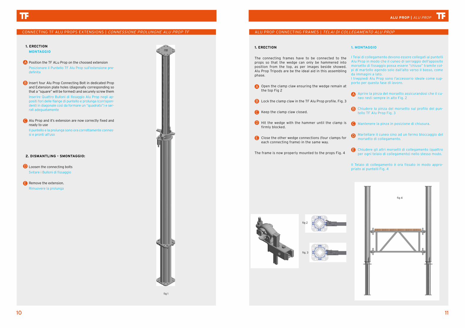
The connecting frames have to be connected to the props so that the wedge can only be hammered into position from the top, as per images beside showed. Alu Prop Tripods are be the ideal aid in this assembling phase.
Open the clamp claw ensuring the wedge remain at the top Fig 2
Lock the clamp claw in the TF Alu Prop profile. Fig. 3
Keep the clamp claw closed.
Hit the wedge with the hammer until the clamp is firmly blocked.
Close the other wedge connections (four clamps for each connecting frame) in the same way.
The frame is now properly mounted to the props Fig. 4
1. MONTAGGIO
I Telai di collegamento devono essere collegati ai puntelli Alu Prop in modo che il cuneo di serraggio dell’apposito morsetto di fissaggio possa essere “chiuso” tramite col-pi di martello agendo solo dall’alto verso il basso, come da immagini a lato.I treppiedi Alu Prop sono l’accessorio ideale come sup-porto per questa fase di lavoro.
Aprire la pinza del morsetto assicurandosi che il cu-neo resti sempre in alto Fig. 2
Chiudere la pinza del morsetto sul profilo del pun-tello TF Alu Prop Fig. 3
Mantenere la pinza in posizione di chiusura.
Martellare il cuneo sino ad un fermo bloccaggio del morsetto di collegamento.
Chiudere gli altri morsetti di collegamento (quattro per ogni telaio di collegamento) nello stesso modo.
Il Telaio di collegamento è ora fissato in modo appro-priato ai puntelli Fig. 4
A
A
B
BC
CD
DE
E
fig 4
fig 2
fig. 3
CONNECTING TF ALU PROPS EXTENSIONS | CONNESSIONE PROLUNGHE ALU PROP TF
1. ERECTION
MONTAGGIO
Position the TF ALu Prop on the choosed extension
Posizionare il Puntello TF Alu Prop sull’estensione pre-definita
Insert four Alu Prop Connecting Bolt in dedicated Prop and Extension plate holes (diagonally corresponding so that a “square” will be formed) and securely screw them
Inserire Quattro Bulloni di fissaggio Alu Prop negli ap-positi fori delle flange di puntello e prolunga (corrispon-denti in diagonale così da formare un “quadrato”) e ser-rali adeguatamente
Alu Prop and it’s extension are now correctly fixed and ready to use
Il puntello e la prolunga sono ora correttamente connes-si e pronti all’uso
2. DISMANTLING - SMONTAGGIO:
Loosen the connecting bolts
Svitare i Bulloni di fissaggio
Remove the extension.
Rimuovere la prolunga
A
D
E
B
C
fig 1

12 13
ALU PROP | ALU PROP
ALU PROP WALING CONNECTOR | CONNETTORE CORRENTI ALU PROP
In presence of high loads, steel walers can be adopted as main beams, and can be fixed to the props instead of H20 wooden beams, i.e. when configuring TF Alu Prop shoring towers as “Table System”.
1. ERECTION
Loosen the Nut M 16 on threaded rod M 16 (1)
Position the connecting plate on U-profile top wings (2)
Insert the fixing hooks, from below, in the holes of the prop head plate (3)
Tighten the Nut M 16 on threaded rod M 16
2. DISMANTLING
Loosen the Nut M 16 on threaded rod M 16 (1)
Pull the fixing hooks out of the prop head plate and remove the connecting plate.
In presenza di carichi elevate, correnti in acciaio pos-sono essere adottati e fissati ai puntelli al posto delle comuni travi in legno H20. p.e. : configurando il Sistema TF Alu Prop come “Tavolo Solaio”.
1. MONTAGGIO
Svitare il dado M 16 dalla barra filettata M 16 (1)
Posizionare la piastra di collegamento sulle ali su-periori del profilo ad U (2)
Inserire i ganci di fissaggio, dal basso, nei fori della flangia di testa del puntello (3)
Serrare i dadi M 16 sulle barre filettate M 16
2. SMONTAGGIO
Svitare i dadi M 16 dalla barra filettata M 16
Sfilare i ganci di fissaggio dalla flangia di testa del puntello e rimuovere la piastra di collegamento
A
A
A
A
B
B
B
B
C C
D D
fig 5
1 4
2
3

14 15
ALU PROP | ALU PROP
2 1
TF ALU PROP CONNECTION | GIUNZIONE PUNTELLI TF ALU PROP:
TF ALU PROP CONNECTING BOLT – BULLONE DI FISSAGGIO ALU PROP
The Connecting Bolt allow to “couple” two Alu Props trough their end plate ( four bolts for each connection) Fig. 8
1. ERECTION:
Position the two props on top of each other mak-ing sure the flanges match precisely (1)
Insert four Connecting Bolts “diagonally” so that they form a “square” (2)
Screw the Bolts securily.
The props are now connected and ready to use Fig. 9.
BULLONE DI FISSAGGIO ALU PROP
Il Bullone di Fissaggio permette la giunzione di due puntelli Alu Prop fissandone le flange (quattro bulloni per ogni giunzione) Fig. 8
1. MONTAGGIO:
Posizionare I due puntelli uno sull’altro assicurando-si che le flange si sovrappongano precisamente (1)
Predisporre quattro Bulloni di Fissaggio “in diago-nale” così che formino un quadrato (2)
Serrare I Bulloni in modo adeguato.
I puntelli sono ora connessi e pronti all’uso Fig. 9.
A A
B B
C C
fig 8
fig 9
ASSEMBLING INSTRUCTIONS | ISTRUZIONI DI MONTAGGIO
TF ALU PROP PREPARATION
Press the safety hook (1) and release the adjusting nut (2).
Extract the inner tube (3) to required prop length.
The inner tube have to be pushed in until the adjust-ing nut lies on the bearing plate (4).
Lock the safety hook (1).
Adjust to the exact prop length by screwing the ad-justing nut (2).
PREPARAZIONE PUNTELLI TF ALU PROP:
Aprire il gancio di sicurezza (1) e svitare la ghiera di regolazione (2).
Estrarre il tubo interno sino alla necessaria lunghezza (3).
Il tubo interno deve essere spinto verso l’interno sino all’appoggio della ghiera di regolazione sulla flangia portante (4).
Fissare il gancio di sicurezza (1)
Regolare sino alla precisa misura operativa del pun-tello avvitando la ghiera di regolazione (2).
Il puntello TF Alu Prop è ora pronto per l’utilizzo Fig. 7
A
32 1
4
A
B B
C C
DD
EE
fig 7

16 17
ALU PROP | ALU PROP
TF ALU TOWERS HORIZONTAL ASSEMBLY | ASSEMBLAGGIO ORIZZONTALE TORRI ALU TF
fig 11 fig 12
fig 13
1
2
fig 14
fig 15
TF ALU TOWERS HORIZONTAL ASSEMBLY | ASSEMBLAGGIO ORIZZONTALE TORRI ALU TF
Because of safety considerations, the horizontal assembly is recommended in order to minimize any avoidable risk for workers. An adequately levelled area is necessary to correctely execute the horizontal assembly.
1. ERECTION:
Adjust the props length as previously described in “System Details” paragraph.
Lay down both props and connecting frames in planned configuration, the images are just an example Fig. 10.
Connect the props with each other and the connecting frames (Fig. 11) to the props as per related instructions Fig. 12
Fix following connecting frames in vertical direction (1) and, after preparing by connecting them the fol-lowing “couple” of Alu Props, lay them on top of the connecting frames (2), executing the connections with the same sequence and recommendations described in previous phases Fig. 13.
Complete the tower assembly by connecting the last connecting frames as per previous instructions Fig.14.
The Alu Tower is now ready to use and can be lifted by crane ropes or chains to the foreseen operative posi-tion Fig. 15.
Before to lift and shift in working position the Alu Tower, carefully check any connection as props adjoining by con-necting bolts, connecting frames wedge connectors etc… visually and mechanically.
Per ragioni di sicurezza, si raccomanda l’assemblaggio in orizzontale per ridurre al minimo ogni possibile rischio per gli operatori. E’ necessaria un’area piana adeguata per la corretta esecuzione dell’assemblaggio orizzontale.
1. MONTAGGIO:
Regolare la lunghezza dei puntelli come descritto in precedenza al paragrafo “Istruzioni di montaggio”
Posizionare a terra puntelli e telai di collegamento come da configurazione prevista. Le immagine sono solo un esempio Fig. 10.
Connettere i puntelli fra di loro ed i telai di collega-mento (Fig. 11) ai puntelli come da relative istruzioni precedenti Fig. 12.
Fissare i telai di collegamento successivi in verti-cale (1); dopo aver preparato la coppia di puntelli successivi, posizionarli sui telai di collegamento (2), eseguendo la stessa sequenza, con le stesse raccomandazioni, descritta in precedenza Fig. 13.
Completare l’assemblaggio della torre fissando gli ultimi telai di collegamento come da istruzioni precedenti Fig. 14
La Torre Alu è ora pronta all’uso e può essere sol-levata mediante funi o catene per gru e spostata nella sua posizione di lavoro Fig. 15
Prima di sollevare e spostare in posizione di lavoro la Torre Alu, verificare con cura ogni connessione quali le giunzioni dei puntelli con bulloni di fissaggio, I morsetti a cuneo dei telai di collegamento etc.… sia visivamente che meccanicamente
A A
B B
C
DD
EE
FF
C
fig 10

18 19
ALU PROP | ALU PROP
TF ALU TOWERS VERTICAL ASSEMBLY | ASSEMBLAGGIO VERTICALE TORRI ALU TF
fig 18
fig 19
TF ALU TOWERS VERTICAL ASSEMBLY | ASSEMBLAGGIO VERTICALE TORRI ALU TF
If site conditions or other stringent reasons make it im-possible to operate horizontally, then a vertical assembly procedure have to be considered and applied, taking on account every possible safety measure to avoid risks as much as possible, i.e. only anti-slipping material as work-ing base (walking boards in vertical working steps), every worker wearing safety harness, tower stability checked and guaranteed etc…
1. ERECTION:
Adjust the props length as previously described in “System Details” paragraph.
Put the props in vertical position by the aid of TF Alu Prop Tripod Fig. 16
Install the necessary connecting frames as per previ-ous instructions Fig. 17
To proceed further in height and install Alu Tower next levels a safe decking , also made by scaffolding boards, have to be foreseen and appropriately installed by the appointed construction company Fig. 18. Connecting Frames can act as perimeteral protections and there-for can be mounted in addition in respect to the neces-sary number for tower configuration
2. FURTHER LEVELSAny further levels will follow the same procedure previous-ly described. Before to lift and shift in working position the Alu Tower, carefully check any connection as props adjoin-ing by connecting bolts, connecting frames wedge connec-tors etc… visually and mechanically
Se le condizioni di cantiere o altre pressanti ragioni impedis-cono di assemblare in orizzontale, si può prevedere ed es-eguire una procedura di assemblaggio verticale, avendo es-trema cura nell’evitare ogni rischio per i lavoratori, adottando ogni possibile misura di sicurezza (come ad esempio l’utilizzo di materiali antiscivolo nella realizzazione dei piani di lavoro, l’utilizzo da parte di tutti i lavoratori interessati delle imbra-cature di sicurezza per le lavorazioni in quota, la verifica e la garanzia della stabilità della torre in fase di montaggio etc.…)
1. MONTAGGIO:
Regolare la lunghezza dei puntelli come descritto in precedenza al paragrafo “Istruzioni di montaggio”
Posizionare i puntelli in posizione verticale con l’aiuto dei Treppiedi TF Alu Prop Fig.16.
Installare i Telai di collegamento necessari come da istruzioni precedenti Fig. 17
Per procedere in altezza ed installare i vari livelli della Torre Alu, necessitano piani di lavoro sicuri da realizzarsi con appropriati materiali e/o ponteggi, a cura dell’impresa realizzatrice delle strutture Fig. 18. I telai di collegamento possono fungere da parapetti di protezione e si posso-no quindi prevedere telai addizionali rispetto a quanto necessario per la configurazione della torre.
2. LIVELLI ULTERIORI:
Ogni livello ulteriore della torre seguirà la stessa proce-dura descritta in precedenza. Prima di sollevare e spostare in posizione di lavoro la Torre Alu, verificare con cura ogni connessione quali le giunzioni dei puntelli con i Bulloni di fis-saggio, i morsetti a cuneo dei Telai di collegamento etc.… sia visivamente che meccanicamente.
AA
BB
C
DD
C
fig 16 fig 17

20 21
ALU PROP | ALU PROP
ALUMINIUM PROPS P 105
PUNTELLI IN ALLUMINIO P 105
ALUMINIUM PROPS P 70
PUNTELLI IN ALLUMINIO P 70
CODECODICE
DESCRIPTIONDESCRIZIONE
WEIGHT (KG)PESO (KG)
PUNT1600105VPuntello alluminio 105
1000/1600 mmAlu Prop 105 1000/1600 mm
13,0
PUNT2500105VPuntello alluminio 105
1450/2500 mmAlu Prop 105 1450/2500 mm
17,0
PUNT3500105VPuntello alluminio 105
1950/3500 mmAlu Prop 105 1950/3500 mm
21,5
PUNT4200105VPuntello alluminio 105
2650/4200 mmAlu Prop 105 2650/4200 mm
23,0
PUNT4800105VPuntello alluminio 105
2600/4800 mmAlu Prop 105 2600/4800 mm
27,5
PUNT5500105VPuntello alluminio 105
3300/5500 mmAlu Prop 105 3300/5500 mm
30,5
PUNT6250105VPuntello alluminio 105
4300/6250 mmAlu Prop 105 4300/6250 mm
35,0
CODECODICE
DESCRIPTIONDESCRIZIONE
WEIGHT (KG)PESO (KG)
PUNT305070VPuntello alluminio 70
1750/3050 mmAlu Prop 70 1750/3050 mm
11,5
PUNT420070VPuntello alluminio 70
2900/4200 mmAlu Prop 70 2900/4200 mm
16,5
ALU PROP CONNECTING FRAMES
TELAI DI COLLEGAMENTO ALU PROP
CODECODICE
DESCRIPTIONDESCRIZIONE
WEIGHT (KG)PESO (KG)
TL500105SZSteel frame 500 mm galvanized
Telaio 500 mm zincato completo
6,5
TL1000105SZSteel frame 1000 mm galvanized
Telaio 1000 mm zincato completo
9,3
TL1250105SZSteel frame 1250 mm galvanized
Telaio 1250 mm zincatocompleto
10,5
TL1500105SZSteel frame 1500 mm galvanizedTelaio 1500 mm zincato com-
pleto11,5
TL2000105SZSteel frame 2000 mm galvanized
Telaio 2000 mm zincato completo
14,0
TL2500105SZSteel frame 2500 mm galvanized
Telaio 2500 mm zincato completo
15,7
ITEMS LIST | LISTA COMPONENTITF ALU TOWERS TUBE & COUPLERS BRACING | CONTROVENTATURE A TUBO & GIUNTO TORRI ALU TF
TRANSPORT & STORAGE | TRASPORTO E STOCCAGGIO
On site it’s not unsual to have the necessity to provide specific bracings not easy to foresee beforehand; other than above mentioned situations and specific needs, the “Tube & Couplers” bracing system could be an helpful aid also during the assembling phase. In any case, the Alu Prop “Clamp & Coupler” Fig. 22, is the ideal item to combine the TF Alu Prop with standard tubes to be used as bracings Fig. 20 – 21.
In cantiere non è raro il dover provvedere a controventat-ure specifiche non prevedibili a priori; oltre a quanto sopra, il sistema di controventatura a “Tubo e Giunto” può essere un ottimo aiuto nella fase di assemblaggio delle torri.In ogni caso, il “Morsetto & Giunto” Alu Prop Fig. 22, è l’articolo ideale per combinare i Puntelli Alu Prop con I tubi standard da utilizzarsi come controventi Fig. 20-21.
fig 21fig 22
fig 20
Imbal Props (49/pcs)
Imbal Frames (20/pcs)

22 23
ALU PROP | ALU PROP
ALU PROP WALING CONNECTOR
CONNETTORE CORRENTI ALU PROP
ALU PROP CONNECTING BOLT
BULLONE DI FISSAGGIO ALU PROP
ALU PROP TRIPOD
TREPPIEDE ALU
ALU PROP CLAMP & COUPLER
MORSETTO & GIUNTO ALU PROP
CODECODICE
DESCRIPTIONDESCRIZIONE
WEIGHT (KG)PESO (KG)
TF5821220AAlu Prop Waling connector Connettore Correnti Alu Prop
1,5
CODECODICE
DESCRIPTIONDESCRIZIONE
WEIGHT (KG)PESO (KG)
bolt M12Alu prop Connecting BoltBullone di fissaggio Alu prop
0,2
CODECODICE
DESCRIPTIONDESCRIZIONE
WEIGHT (KG)PESO (KG)
TPR116 Alu Prop TripodTreppiede Alu
11,00
CODECODICE
DESCRIPTIONDESCRIZIONE
WEIGHT (KG)PESO (KG)
TF5825610AAlu Prop Clamp & Coupler Morsetto & Giunto Alu Prop
4
ALU PROP EXTENSIONS
PROLUNGHE PUNTELLI ALUCODE
CODICEDESCRIPTIONDESCRIZIONE
WEIGHT (KG)PESO (KG)
P500105VProp extension L500 mm
Prolunga puntello L500 mm3,5
P1000105VProp extension L1000 mm
Prolunga puntello L1000 mm5,7
P1500105VProp extension L1500 mm
Prolunga puntello L1500 mm8,0
P2000105VProp extension L2000 mm
Prolunga puntello L2000 mm10,2
P3000105VProp extension L3000 mm
Prolunga puntello L3000 mm14,8
22

THE FORMWORK SRL
Via Achille Grandi, 7 - 20097 San Donato Milanese (Milano) - Italy
Tel. +39 02 5275829 - 02 5279974 - Fax +39 02 55600291
[email protected] | www.theformwork.it