aluminart/chamberdoor warrants that any part lost or mis · aluminart/chamberdoor warrants that the...
TRANSCRIPT

Page 1 of 12 Rev. May 2013 Part No. 14169
Warranty applies to original purchaser of door only; covers manufacturer’s defects only.
Aluminim Door Series Warranty Century Series Lifestyle Series Northern/Fiera Series
Limited Lifetime Warranty - During the life of the door, AluminArt/ChamberDoor will warranty all manufacturer’s defects. A nominal processing fee will apply.
Classic Series National Series
7 Year Limited Warranty - For seven years, AluminArt/ChamberDoor will warranty all manufacturer’s defects. A nominal processing fee will apply.
Value Series 5 Year Limited Warranty - For five years, AluminArt/ChamberDoor will warranty all manufacturer’s defects. A nominal processing fee will apply.
Woodcore Door Series Warranty Premier Series
Limited Lifetime Warranty - During the life of the door, AluminArt/ChamberDoor will warranty all manufacturer’s defects. A nominal processing fee will apply. After 10 years, the consumer is responsible for shipping and handling costs.
Advantage Series Weatherguard Series
5 Year Limited Warranty - For five years, AluminArt/ChamberDoor will warranty all manufacturer’s defects. A nominal processing fee will apply.
Storm Door Warranty Limitations: • Warranty only applies to original homeowners of owner-occupied residential properties and covers manufacturer’s defects. • Modification of door will void warranty. • Wind damage is not covered under warranty. • Labor cost, re-installation fees are not covered under warranty. • Water damage due to lack of rain diversion or structural overhang is not covered under warranty. • Damage or breakage to the screen, glass, vinyl, hinges and hinge mounting frame is not covered under warranty. • Damage due to misuse, abuse, improper maintenance, improper installation, alteration or non-residential use is not covered under warranty. • Certain coastal applications and/or the forces of nature including, but not limited to, weathering are not covered under warranty. • Your exclusive remedy is limited to the repair and replacement of defective product.
Door Frame Warranty AluminArt/ChamberDoor warrants that the aluminum components and the woodcore blank of the storm door will not crack, rot, split or rust during the warranty period.
Hardware Warranty
Hardware components, including the handle, latch, locks, closer (and/or assemblies) are free from manufacturing defects for a period of one year from the date of purchase. The LifetimeBrass™ and LifetimeNickel™ finish on the hardware has a lifetime warranty against pitting only.
Retractable Screen Warranty
Retractable screen warranty is one year, covering workmanship, mechanical parts and factory defects. Does not include torn screen.
No Fault Installation
AluminArt/ChamberDoor warrants that any part lost or mis-cut during the original installation of your storm door will be repaired or replaced at no additional charge within ninety (90) days of the date of original purchase. This limited warranty will not apply if the part has been misused, abused or altered. Cutting and mis-drilling parts not specified by the installation guide are not included under this warranty.
ALL IMPLIED WARRANTIES INCLUDING MERCHANTABILITY AND FITNESS FOR A PARTICULAR PURPOSE ARE LIMITED TO THE APPLICABLE STATUTE OF LIMITATION, BUT IN NO CASE WILL EXTEND BEYOND THE TERM OF THE LIMITED WARRANTIES SET FORTH ABOVE. ALUMINART/ CHAMBERDOOR EXCLUDES AND WILL NOT PAY FOR INCIDENTAL OR CONSEQUENTIAL DAMAGES, WHETHER ARISING OUT OF CONTRACT, TORT OR OTHERWISE, AND LIABILITY WILL IN ALL INSTANCES BE LIMITED TO THE REPAIR OR REPLACEMENT OF THE DEFECTIVE PRODUCT. SOME STATES DO NOT ALLOW THE EXCLUSION OF INCIDENTAL AND CONSEQUENTIAL DAMAGES, OR LIMITATION OF THE DURATION OF AN IMPLIED WARRANTY, SO THE ABOVE LIMITATIONS OR EXCLUSIONS MAY NOT APPLY TO YOU. THIS LIMITED WARRANTY GIVES YOU SPECIFIC LEGAL RIGHTS, AND YOU MAY ALSO HAVE OTHER RIGHTS THAT MAY VARY FROM STATE TO STATE AND IN CANADA.
Warranty Replacements: Customer Service Toll Free: 1-800-541-7307 Proof of purchase is required to obtain warranty replacements.
Warranty, Installation & Operation Manual for Aluminum & Woodcore Doors

Part No. 14169 Rev. May 2013 Page 2 of 12
1. Read all instructions carefully before you begin. 2. Check package contents and hardware box(es). 3. Ensure you have necessary tools required to complete installation.
NOTE: On Full Lite doors, the screen insert is secured to the inside of the door with two temporary
4” retainer strips. Before installing the door, discard the 4” strips and set the screen aside.
Storm door, complete with glass insert(s), screen system
Hardware kit(s) includes: Handle assembly Closer assembly
Mounting frame kit includes: Hinge mounting frame Latch mounting frame Header mounting frame Expander sweep system Mounting frame screw covers (Century, Premier - available as an accessory for other series) Installation screw package
From the product code label attached to the door’s top mainframe, record the following information for warranty purposes.
Date of Purchase: Door Name: Door Color: Door Size: Model #: Serial #:
BEFORE YOU BEGIN
CHECK CONTENTS OF STORM DOOR PACKAGE
TOOLS REQUIRED FOR INSTALLATION
DOOR INFORMATON
Carpenter’s level Hacksaw
Phillips screwdriver
Slot screwdriver
File Tape measure
Hammer
Center punch Pliers 7/16” drill bit 1/4” drill bit
1/8” drill bit Pencil
Drill

Page 3 of 12 Rev. May 2013 Part No. 14169
Shim Header brick mould
1. Brickmould is the wooden frame attached to the door opening. The storm door requires a 1” deep by 1” wide minimum brickmould for installation. If required, shim the brickmould to the 1” minimum dimension. See Fig. 1.
2. A 3-3/4” minimum depth is required between the prime door and storm door mounting frame to allow for hard- ware. Build out if required. See Fig. 2.
m
Minimum 1" depth
Prime Door
pump
3-3/4" minimum depth between
brickmould (casing)
Minimum 1"
Storm Door
Fig. 2
NOTE: If the prime door has a non-conventional or ‘slim line’ Brickmould ensure that it is sufficiently and properly shimmed before installing the storm door mounting frame.
Fig.1 Fig.2 Fig. 3
STEP 2 MEASURE/CHECK BRICKMOULD FOR SQUARE AND LEVEL (PLUMB)
Fig. 1
Jamb
Prime door
1" minimum face and depth of
brickmould
Sloped sill
doors
To ensure a proper fitting storm door the brickmould should be square. Standing outside the opening:
1. Measure from top right hand side where the header brickmould and right side brickmould meet diagonally to the lower left hand side of the opening. Record measurement. See Fig. 1.
2. Repeat Step 1 from top left hand side diagonally to lower right hand side. Record measurement. See Fig. 1.
If one measurement is longer, place a shim on the header brickmould so that both measurements are equal within 1/8” of each other. See Fig. 2. The brickmould must be level from top to bottom of the opening on both sides. See Fig.3. If your brickmould is not level add a piece of wood or shim in the appropriate places.
Header Brick mould
Measure brick mould
for level

Part No. 14169 Rev. May 2013 Page 4 of 12
Standing on the outside of the house, facing the doorway, mark hinge side (LEFT or RIGHT) on the outside of the storm door. See Fig. 1 and Fig. 2.
CHECK THAT THE DOOR IS THE RIGHT WAY UP BEFORE INSTALLING THE HINGE MOUNTING FRAME
THE MODEL/SERIAL NUMBER LABEL IS ON THE INSIDE MAINFRAME AT THE TOP OF THE DOOR
For LEFTSIDE hinging, see Fig. 1. For RIGHTSIDE hinging, see Fig. 2.
1. Using the door packaging as a protective pad, place door on its edge with side to be hinged facing up.
2. Position hinged mounting frame on door edge, facing outside of door.
3. Slide each hinge into the hinge interlock and lock into place. This ensures proper fit and operation of hinges.
4. Ensure the hinged mounting frame extends 3/16” beyond the top outside edge of the storm door frame.
5. Pre-drill 1/8” pilot holes through hinge holes and fasten with #8x3/4” screws.
STEP 3 DETERMINING THE HINGE SIDE OF DOOR OPENING
STEP 4 INSTALLING HINGED MOUNTING FRAME TO STORM DOOR
BOTTOM
Weatherstrip
BOTTOMof Door
TOP ofDoor
Weatherstrip
TOP ofDoor
3/16"
INSIDE InterlockHinge
Pilot HolesDrill 1/8"
INSIDE
BOTTOMof Door
Pilot HolesDrill 1/8"
Door
INSIDE
InterlockHinge INSIDE
TOP of
3/16"WeatherstripRIGHTSIDE HINGINGLEFTSIDE HINGING
Fig. 1 Fig. 2
For #8x3/4” Screw For #8x3/4” Screw

Page 5 of 12 Rev. May 2013 Part No. 14169
1. On the hinge side of the opening measure the height of the brickmould, top to bottom.
2. Starting at the top of the hinge-mounting frame, measure down the same distance. Subtract 1/8” and draw a line. You may want to angle the line to follow the slope of your sill.
3. Using a hacksaw, cut the frame on the line.
4. Use a file to remove sharp burrs
The expander sweep is located on the bottom of the door. There are four types: L-Shape (1 fin), L-Shape (2 fin), U-Shape (Aluminum), and U-Shape (Vinyl). Follow instructions that match your sweep.
Before starting this step, complete the next step
“Installing Storm Door / Mounting Frame to Brickmould” first.
1. Position the expander sweep under the door with fin towards the outside. See Fig. 1.
2. Position expander sweep on the bottom inside of door ensuring the ends of the expander align with ends of the doorframe. Ensure that the upward pointing fin folds under the door. See Fig. 2.
3. Drill a 1/8” pilot hole at the bottom of the installation slots and install the #8x3/8” screws in each hole. Lower sweep so the vinyl fin just touches the sill. See Fig. 3
Fig. 1 Fig. 2 Fig. 3
STEP 5 MEASURE AND CUT HINGED MOUNTING FRAME
STEP 6 INSTALLING EXPANDER SWEEP
A INSTALLING “L” SHAPE SINGLE FIN EXPANDER SWEEP
Angle of sloped sill (Optional) Bottom of
mounting frame
Inside bottom edge of door
Expander Sweep
Vinyl Fin
Installation slot pilot hole
Pull sweep to touch sill and tighten screw
Vinyl Fin

Part No. 14169 Rev. May 2013 Page 6 of 12
1. Position expander sweep tight to the bottom inside of door. See Fig. 1. 2. Ensure the upward fin touches and folds under the bottom of the door and the ends of the expander align with
inside edges of storm door. Drill 1/8” pilot hole at the bottom of each installation slot and install the #8x3/8” screws in each hole. See Fig. 2. Lower sweep so the vinyl fin just touches the sill. See Fig. 3.
3. Pull expander down fully and tighten the screws. See Fig. 3
Fig. 1 Fig. 2 Fig. 3
1. Insert the rubber sweep fins that are shipped with the sweep into the T-grooves at the bottom of the aluminum U sweep; trim off excess fin & crimp the aluminum to prevent fin from sliding out. Fig 1. Position the sweep directly below the bottom of the door as shown with the flat side having the slot hole on the inside and the contoured side of the sweep on the outside.
2. Push the sweep upward over the bottom edge of the door. The contoured ends of the sweep are shaped to fit between the metal overlap frames on the side edges of the door. With the sweep held all the way up on the bottom of the door, drive the #8 X 3/8” screws through the bottom part of the slot holes as shown in Fig. 2. Do not fully tighten the screws.
3. Move the sweep downward until the rubber sweep fins make contact with the threshold. Now fully tighten the screws.
Inside bottom edge of door
Drive screw at the bottom of the slot
Slot hole for sweep
Aluminum ‘U’ Expender Sweep
Vinyl Fin x 2 Trim & Crimp
Fig. 1
Push sweep all the way up on bottom of door
Fig. 2
Fig. 3
Pull seep down to touch sill and tighten the screw
1. Position the expander under the door with the “U” shaped rigid plastic section up and the flexible fin down with slot hole on the inside. See Fig. 1.
2. Fit the “U” on the door. Drill 1/8” pilot holes at the centre of the slot hole and install the sweep with #8x3/8” screws in each hole. See Fig. 2.
Fig. 1 Fig. 2
STEP 6 INSTALLING EXPANDER SWEEP
B INSTALLING “L” SHAPE DOUBLE FIN EXPANDER SWEEP
C INSTALLING “U” SHAPE ALUMINUM SWEEP (Woodcore Door)
D INSTALLING “U” SHAPE VINYL SWEEP (Woodcore Door)
door
Expander Sweep
Inside of door
#8x3/8” Screw Pull sweep to lowest
Position and tighten screw

Page 7 of 12 Rev. May 2013 Part No. 14169
1. Position hinged mounting frame tight against the brickmould and hold the door up so that the bottom inside sweep fins just touch the sill. See Fig. 1. If the inside fin binds on the sill, adjust the sweep up.
2. Using #8x1-1/4” screws, install top and bottom screws. Do not over tighten. See Fig. 2. 3. Open and close the door to ensure that it moves freely in the opening. 4. Drill 1/8” pilot hole through the remaining holes and fasten with #8x1-1/4” screws. 5. Open door to expose the hinges. Drive #8x1-1/4” screws through existing holes on z-bar located
above and below each hinge into wood frame. See Fig. 3.
Brickmould Brickmould #8x1-1/4" Screw
Top of door
Hinged mounting frame
Doorframe
OUTSIDE OF DOOR
#8x1-1/4" Screw
Doorframe
OUTSIDE OF DOOR
Fig. 1 Fig. 2 Fig. 3
NOTE: If the prime door has a non-conventional or ‘slim line’ Brickmould ensure that it is sufficiently and properly shimmed before installing the storm door mounting frame.
1. With storm door in an open position, set header mounting frame against the brickmould with one end resting on top of the hinged mounting frame. See Fig. 1.
2. Drill 1-1/8” pilot hole in the hinge mounting frame and fasten with a #8x1-1/4” screw.
3. Holding the other end of the header mounting frame in place, close the door.
4. Maintain an equal gap between the top of the storm door and the header mounting frame.
5. Drill a 1/8” pilot hole in the hole at the other end of the header on the latch side (ensure that the top end of the latch mounting frame touches the end of the header mounting frame. Fasten with a #8x1- 1/4” screw. Repeat the process for the middle hole.
STEP 7 INSTALLING STORM DOOR / MOUNTING FRAME TO BRICKMOULD
STEP 8 INSTALLING HEADER MOUNTING FRAME
Weatherstrip Weatherstrip
Part No. 14169 Rev. May 2013 Page 8 of 12
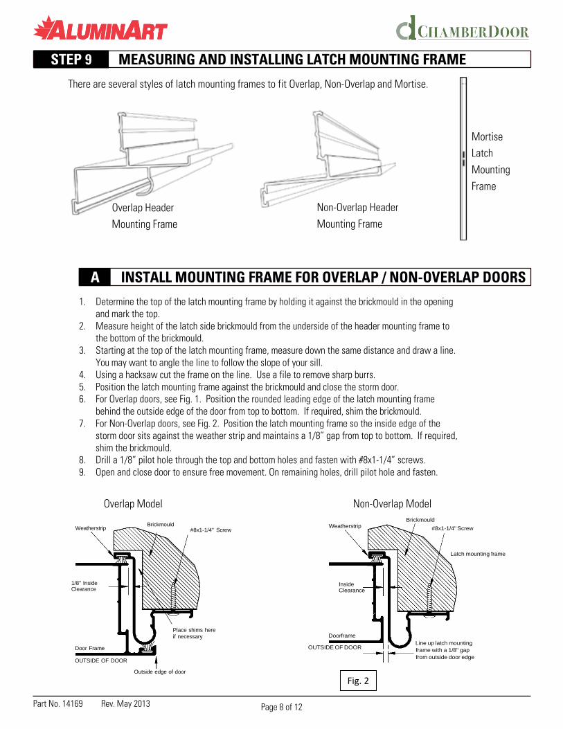
There are several styles of latch mounting frames to fit Overlap, Non-Overlap and Mortise.
Mounting Frame
Non-Overlap Header Mounting Frame
Mortise Latch Mounting Frame
1. Determine the top of the latch mounting frame by holding it against the brickmould in the opening and mark the top.
2. Measure height of the latch side brickmould from the underside of the header mounting frame to the bottom of the brickmould.
3. Starting at the top of the latch mounting frame, measure down the same distance and draw a line. You may want to angle the line to follow the slope of your sill.
4. Using a hacksaw cut the frame on the line. Use a file to remove sharp burrs. 5. Position the latch mounting frame against the brickmould and close the storm door. 6. For Overlap doors, see Fig. 1. Position the rounded leading edge of the latch mounting frame
behind the outside edge of the door from top to bottom. If required, shim the brickmould. 7. For Non-Overlap doors, see Fig. 2. Position the latch mounting frame so the inside edge of the
storm door sits against the weather strip and maintains a 1/8” gap from top to bottom. If required, shim the brickmould.
8. Drill a 1/8” pilot hole through the top and bottom holes and fasten with #8x1-1/4” screws. 9. Open and close door to ensure free movement. On remaining holes, drill pilot hole and fasten.
Overlap Model Non-Overlap Model
Weatherstrip Brickmould
#8x1-1/4" Screw
Weatherstrip
Brickmould
#8x1-1/4" Screw
Latch mounting frame
1/8" Inside Clearance
Inside Clearance
Door Frame
OUTSIDE OF DOOR
Place shims here if necessary
Outside edge of door
Doorframe
OUTSIDE OF DOOR
Line up latch mounting frame with a 1/8" gap from outside door edge
STEP 9 MEASURING AND INSTALLING LATCH MOUNTING FRAME
A INSTALL MOUNTING FRAME FOR OVERLAP / NON-OVERLAP DOORS
Overlap Header
Fig. 2

Page 9 of 12 Rev. May 2013 Part No. 14169
• Cutting The Top Of The Mortise Latch Mounting Frame 1. The mortise latch mounting frame has two rectangles cut out of the side to accept the
latch and deadbolt throw of the mortise style handle. See Fig. 1. 2. Position the latch mounting frame against the brickmould
and mark the top of the latch mounting frame.
Top of latch mounting frame
3. Using the cardboard template, place the pointed end of the plastic pushpin into the center small hole of the latch mounting frame.
4. Rotate the template so the door heights 78, 79, 80, 81, 82,
Top, outside of door
Handle hardware cut Handle hardware cut
83 are at the top of the frame. 5. Match the height of the storm door you purchased to the
same height on the template and mark that hole with a pencil.
6. Remove the template and using a hacksaw cut the frame on your mark as square as possible. Use a file to remove burrs.
out on door edge
Fig. 1
outs on latch mounting frame
• Cutting The Bottom Of The Mortise Latch Mounting Frame 1. Measure height of the latch side brickmould from the underside of the header mounting
frame to the bottom of the brickmould. 2. Starting at the top of the latch mounting frame (previously cut), measure down the same
distance and draw a line. You may want to angle the line to follow the slope of your sill. 3. Using a hacksaw cut the frame on the line.
Use a file to remove burrs. 4. Position the latch mounting frame against
the brickmould and close the storm door. See Fig. 2.
5. Position the rounded leading edge of the latch mounting frame behind the outside edge of the door from top to bottom.
6. If required, shim the brickmould. 7. Drill a 1/8” pilot hole through the top and
bottom holes and fasten with #8x1-1/4” screws.
8. Open and close door to ensure free movement.
9. On remaining holes, drill pilot hole and fasten.
Weatherstrip
Inside Clearance
Minimum 3/4" cut out depth for handle hardware
Doorframe
OUTSIDE OF DOOR
Brickmould
#8x1-1/4" Screw
Latch mounting frame
Outside edge of door
STEP 9 (Cont.) MEASURING AND INSTALLING LATCH MOUNTING FRAME
B INSTALLING MORTISE LATCH MOUNTING FRAME

Part No. 14169 Rev. May 2013 Page 10 of 12
Fig. 2
All Century, All Premier Series, Titan, Clearvue, Astra only available as an accessory for other series
Screw covers are installed onto mounting frames to hide the screws and give your opening a cleaner look.
1. Measure and record mounting frame measurements. 2. Cut each length of vinyl screw cover to the recorded mea
surement, using a fine tooth hack saw. 3. Install side mounting frames first. Starting at top of side
mounting frame, place lower edge of screw cover into inner edge of mounting frame channel, working your way to bottom. See Fig. 1.
4. Starting at top of side mounting frame, press higher edge of screw cover into outer edge of mounting frame channel, working your way to bottom. See Fig. 2.
5. For the header, place lower edge of screw cover into edge of mounting frame closest to door. Press higher edge of screw cover into outer edge of mounting frame channel, working your way across.
Install the handle hardware and closer system as per the instructions provided in the handle hardware kit and the closer system kit, included with the storm door. Your installation is now complete.
NOTE: Your door may include the Dual AUTO HOLD™ closer, which is shipped in the off position. To set the AUTO HOLD™ feature follow the instructions on the closer label before installing.
Outside of door
Doorframe
Fig. 1
STEP 10 INSTALLING MOUNTING FRAME SCREW COVERS
STEP 11 INSTALLING THE DOOR HARDWARE
Mounting Frame Measurements
Header mounting frame
Latch mounting frame
Hinged mounting frame
Inner edge of Mounting frame
Outer edge of Mounting frame
#8x1¼” Screw
Higher edge Of screw cover
Lower edge Of screw cover
Mounting frame
Outside of door
Screw cover
Mounting frame

Page 11 of 12 Rev. May 2013 Part No. 14169
The baked enamel finish on your storm door is chip and scratch resistant. Clean with mild detergent and water. Do not use abrasive powders, steel wool, solvents or commercial glass cleaners on the enamel surface. Applying a quality car wax to the aluminum surfaces will maintain the finish of the door.
The glass supplied on your door is break resistant, tempered safety glass. Clean glass with a mixture of vinegar and water.
The Lifetime Brass™ handles feature a titanium coating bonded to the surface. Over time small white spots (salt and mineral deposits) may appear on the surface. These spots can be removed using an all purpose household cleaner and a soft cloth. Do not use abrasive cleaners or cloths as they may damage the titanium coating. The white spots are not the beginning of tarnishing.
EASY VENTILATION: If the door receives direct sunlight most of the day, heat build-up may occur between the storm door and entranceway door due to lack of ventilation. All Aluminart doors have ventilation options. You may raise the storm sweep slightly, leave the sash open, or if your door is a Full Lite, use the screen insert during the affected months.
IMPORTANT: Hold the insert in place while removing the last vinyl retainer.
1. Wrap tip of slot screwdriver with tape to protect doorframe.
2. At one end of retainer, place screwdriver blade into retainer groove.
3. Push firmly toward center of insert. Repeat process every 4 inches.
Protective tape
Retainer Strip
To ease installation, rub a bar of soap along narrow edge of retainer.
1. Position and hold insert in doorframe. Install the longer side retainers first.
2. Starting at one end, place narrow edge of retainer in the groove between insert and doorframe. See Fig. 1.
3. Push retainer towards doorframe, working down the length of the retainer. See Fig. 2 and Fig. 3.
Retainer Strip
( 2
Retainer Strip
Snap In
GENERAL CARE AND MAINTENANCE
HOW TO REMOVE GLASS OR SCREEN INSERTS USING VINYL RETAINERS
HOW TO INSTALL GLASS OR SCREEN INSERTS ON FULL LITE DOORS

Part No. 14169 Rev. May 2013 Page 12 of 12
Your door may have the screen system positioned in the top or bottom half of the door. Follow instructions that match your screen position.
• Screen in Top of Door - Includes View And Vent™
OPENING INSERT: In the closed position the bottom of the sliding glass insert interlocks with the crossbar. To open insert for ventilation, follow the 3 steps in the pictures
Depress latches and push glass insert upwards.
Slightly pull the glass insert to- wards you to clear the crossbar.
Lower the glass insert to the desired posi- tion for ventilation. Ensure latches lock into the channel holes before releasing the handle rail.
CLOSING INSERT: To close insert and set the interlock, follow the 3 steps in the pictures.
Depress latches and push glass insert all the way to the top.
Push the glass insert towards the outside.
Lower the glass insert so it rests on the crossbar. This engages the interlock system.
• Screen in Bottom of Door
1. To raise sliding glass insert, hold handle rail, depress both latches at bottom corners of insert and lift into position. 2. Ensure latches release into precut holes in the channel. 3. To close insert, hold handle rail, depress latches and lower to bottom of window opening.
HOW TO OPEN / CLOSE SLIDING GLASS INSERT FOR VENTILATION