amateur radio service technician class - k7ojl.com · yagi, quad, and dish are all ... 75 ohms …...
TRANSCRIPT

Amateur Radio Service Technician Class
Exam Preparation Class January 2019
Session 2 Roland K. Smith K7OJL
Phone: (435) 849-1946 Email: [email protected]
1 TechClass-Session2.key - January 11, 2019
These slides are uploaded to my website
https://k7ojl.com/class-course-materials/technician-class-materials/
just before class each week.
Depending on how the class goes, they may get updated after the class.
2 TechClass-Session2.key - January 11, 2019
Class Overview
Questions? Reprise
Technician Privileges Propagation Antennas and Feed lines Let’s Go to Space Digital Communications Modes
3 TechClass-Session2.key - January 11, 2019

Questions from Session 1? Questions about Amateur Radio?
4 TechClass-Session2.key - January 11, 2019

Technician Privileges (reprise)
5 TechClass-Session2.key - January 11, 2019
Important FactoidsTechnicians have HF phone privileges only on 10 meters HF has the advantage over VHF and higher frequencies of long-distance skywave propagation Technicians have HF RTTY (teletype) privileges on 10 meters The best time for long-distance 10 meter band propagation via the F layer is from dawn to shortly after sunset during periods of high sunspot activity “Beacons” are deployed by other amateurs around the world to help identify when communications between two points might be possible and to perform similar experimental activities
6 TechClass-Session2.key - January 11, 2019

Propagation
It All Depends on the Sun!
7 TechClass-Session2.key - January 11, 2019

The Ionosphere
8 TechClass-Session2.key - January 11, 2019

The ‘D’ Layer
Appears during daytime Closest to the earth (35 to 55 miles above the earth surface) Many more neutral molecules rather than ionized molecules Significantly attenuates medium frequency and high frequency (below 10 MHz) radio waves
9 TechClass-Session2.key - January 11, 2019

The ‘E’ LayerAppears during daytime Middle ionospheric layer (55 to 95 miles Significant amounts of ionized oxygen molecules Reflects radio frequencies below 10 MHz and may attenuate higher frequencies Occasionally sporadic E events occur where frequencies up to 50 MHz are reflected
10 TechClass-Session2.key - January 11, 2019

The ‘F’ Layers
Splits into the F1 / F2 layers during daytime Combines into one F layer during the night Highest ionospheric layer (90 to 130 miles Responsible for almost all of the high frequency (above 10 MHz) skywave propagation
11 TechClass-Session2.key - January 11, 2019

Sunspots Play a Significant Role in Propagation
Sunspots are dark regions on the face of the sun caused by magnetic field concentrations Sunspots emit considerable magnetic and photon activity which is what ionizes the ionosphere Sunspots ebb and flow in 11 year cycles. We are currently at a sunspot minimum between cycle 24 and cycle 25 The Solar Flux Index indicates how ionized the ionosphere is. An index of 70 or less indicates very poor conditions. On the date this slide was prepared, the solar flux was 72
12 TechClass-Session2.key - January 11, 2019
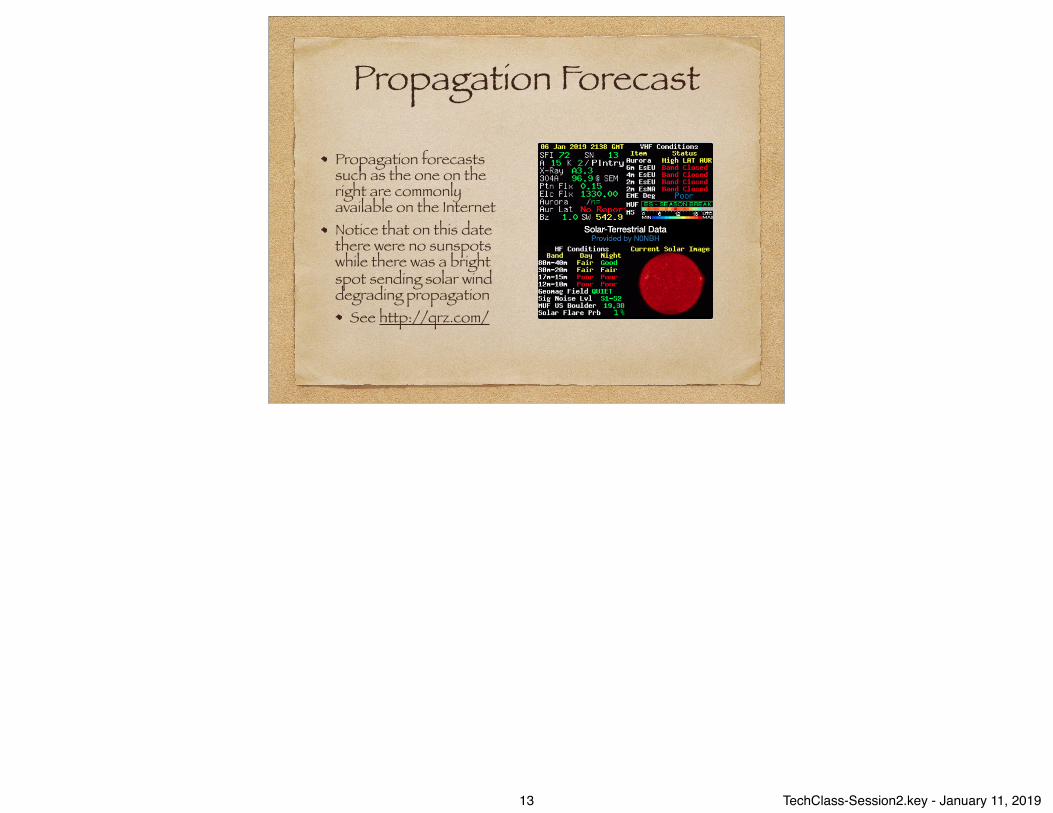
Propagation Forecast
Propagation forecasts such as the one on the right are commonly available on the Internet Notice that on this date there were no sunspots while there was a bright spot sending solar wind degrading propagation
See http://qrz.com/
13 TechClass-Session2.key - January 11, 2019
Propagation FactoidsVHF and UHF frequencies are generally not affected by the ionosphere, meaning they travel in a straight line forever without being reflected back to the earth VHF and UHF radio waves are affected by vegetation — trees and such. In winter these radio waves travel further due to lack of foliage VHF radio waves in vertical orientation tend to “bend” over hills or tall buildings. This is called knife-edge diffraction. Occasionally (usually in summer) temperature layers may occur opening tropospheric “ducts” which can carry VHF radio waves very long distances of 300 miles or so Frequencies below 220 MHz are generally unaffected by fog or rain. Microwave radio waves can be significantly affected by rain and water vapor in the air
14 TechClass-Session2.key - January 11, 2019
More FactoidsWhile VHF and higher frequencies are not reflected by the ionosphere, they can be reflected by meteors, aurora, airplanes, and the moon
Six and two meter waves reflect off auroras giving a fluttery distorted signal, a characteristic of aurora scatter Six meter frequencies work best with meteor scatter
The ten meter band is an amazing band during periods of high sunspot activity with very long distance propagation possible from just before sunrise until shortly after sunset. Note that Technicians have phone (SSB) privileges on portions of the ten meter band! Sporadic E propagation, mentioned earlier, occasionally occurs during late spring and summer on the 10, 6, and 2 meter bands where propagation of thousands of miles is possible
15 TechClass-Session2.key - January 11, 2019

Space Weather Woman
Dr. Tamitha Skov Produces a weekly propagation forecast published on YouTube https://www.youtube.com/channel/UCkXjdDQ-db0xz8f4PKgKsag
16 TechClass-Session2.key - January 11, 2019

Antennas and Feed Lines
17 TechClass-Session2.key - January 11, 2019

Antenna PolarizationAntenna polarization is important at VHF and higher frequencies.
The position of the antenna determines the electrical polarization: vertical, horizontal, or circular A signal from a horizontally polarized antenna will be significantly attenuated by a vertical receiving antenna VHF and UHF FM radios are standardized around vertical polarization (including repeaters), so how you hold your HT makes a difference VHF and higher SSB and Digital modes are generally horizontally polarized
HF frequencies are usually unaffected by polarization and the ionosphere often reverses the polarization anyway
18 TechClass-Session2.key - January 11, 2019
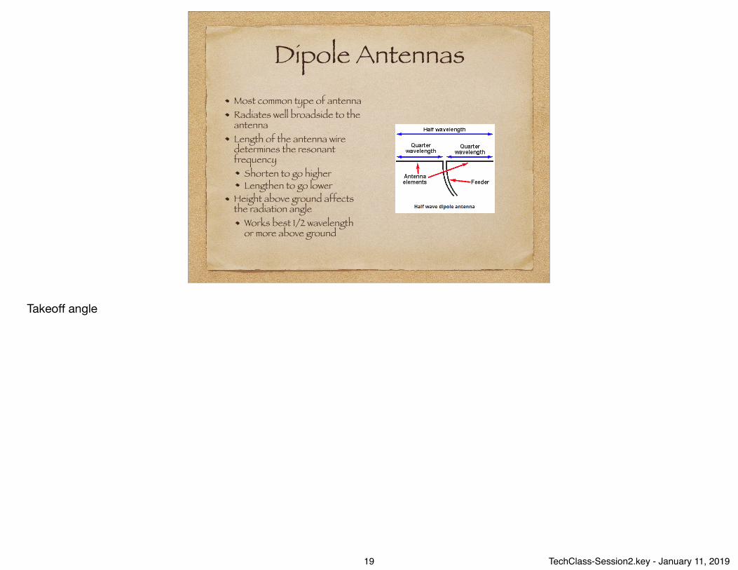
Dipole AntennasMost common type of antenna Radiates well broadside to the antenna Length of the antenna wire determines the resonant frequency
Shorten to go higher Lengthen to go lower
Height above ground affects the radiation angle
Works best 1/2 wavelength or more above ground
Takeoff angle
19 TechClass-Session2.key - January 11, 2019

Dipole Radiation Pattern
20 TechClass-Session2.key - January 11, 2019

How Long Should A Dipole Be?
Length in feet = 468 / frequency in MHz Remember the formula to convert wavelength into frequency
A 6 meter half-wave dipole? 6 meters = 50 MHz (300/6) length = 468 / 50 = 9.36 feet = 112.3 inches
21 TechClass-Session2.key - January 11, 2019

Vertical Antennas
Vertical antennas have a vertical element (1/4 wavelength) and several radials, also 1/4 wavelength, along the ground They have a very low takeoff angle (good for distant contacts) More susceptible to noise than horizontal dipoles
22 TechClass-Session2.key - January 11, 2019

Vertical Antenna Radiation Pattern
23 TechClass-Session2.key - January 11, 2019
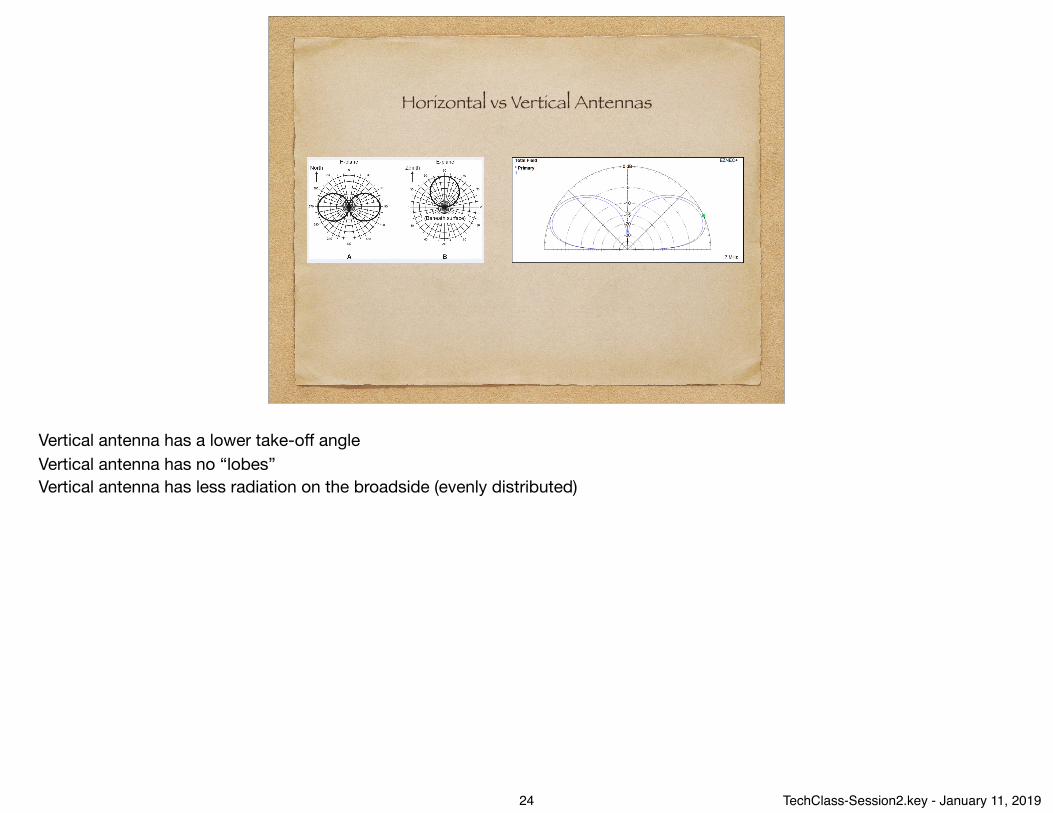
Horizontal vs Vertical Antennas
Vertical antenna has a lower take-off angleVertical antenna has no “lobes”Vertical antenna has less radiation on the broadside (evenly distributed)
24 TechClass-Session2.key - January 11, 2019

Directional Antennas
Yagi, Quad, and Dish are all types of directional antennas
Directional means that the radiation pattern is more focused than a dipole or a vertical antenna
Directional antennas have more “gain” and a higher “front to back ratio”
Gain: a process of taking RF energy and focusing it in an intended directionFront to Back Ratio: The relative signal strength at the front of the antenna vs the relative signal strength at the back of the antennaDirectional antennas a very useful for radio direction finding
25 TechClass-Session2.key - January 11, 2019

Yagi Antenna Radiation Patten
To focus the beam in the vertical: add elements to the beamTo focus the beam in the horizontal: stack another yogi
26 TechClass-Session2.key - January 11, 2019

Feed Lines
Two main types: ladder line (aka window line) and coax
Coax is used most often because of ease of use and no stand-off need Ladder line has the lowest loss
Each type of feed line has differing characteristic impedance
The antenna connector on the back of the transmitter / receiver expects to see an impedance (resistance) of 50 ohmsCoax generally has either 50 ohms or 75 ohms of impedance (50 ohms … amateur; 75 ohms … TV)
27 TechClass-Session2.key - January 11, 2019

Antenna ImpedanceThe impedance at the feed point varies across the length of the antenna If the impedance of the antenna at the feed point varies much from the impedance of the feed line, some of the energy is reflected back towards the transmitter rather than going into the antenna If the mismatch is greater than 3:1 (150 ohms at the feed point from 50 ohm coax), then the transmitter may “fold back” the power to reduce chance of damage to the final amplifier
The method to address the mismatch is to insert a “transmatch” (short for transformer match) between the feed line and the antennaAlternatively, a transmatch is often inserted between the transmitter and the feed line to be sure that the transmitter always sees 50 ohms regardless of the mismatchAnother name for the trans match is an “antenna tuner” … which doesn’t tune anything
28 TechClass-Session2.key - January 11, 2019

Standing WavesThe amount of power reflected back to the transmitter varies with the mismatch The returning wave combines with the transmitted wave to cause a “standing wave” on the feed line. The ratio between the transmitted wave and the reflected wave is called the “Standing Wave Ratio” Eventually the energy not getting into the antenna goes up in heat in the coax. The greater the SWR, the more heat
29 TechClass-Session2.key - January 11, 2019
Antenna / Feed Line FactoidsA 5/8 wave vertical antenna has higher gain and a “squashed” signal pattern vs a 1/4 wave antenna
Often used for mobile antennas Inductance coils are used to electrically lengthen shorter antennas. These coils are often located in the center of the vertical antenna All feed lines have loss. The longer the feed line, the more loss. Coax has significantly more loss than window line but is easier to use
The difference between RG-8 and RG-58 is the latter has more loss than the former
Coax must be protected against moisture incursion. The copper braid will disintegrate Air-insulated hardline: lowest loss, hardest to use, install, and maintain
30 TechClass-Session2.key - January 11, 2019

Coax Cable Loss per 100 Feet
Coax Type
Size Loss at HF 100 MHz
Loss at UHF 400 MHz
RG-58U Small 4.3 dB 9.4 dB
RG-8X Medium 3.7 dB 8.0 dB
RG-8U Large 1.9 dB 4.1 dB
RG-213 Large 1.9 dB 4.5 dB
Hardline Large, Rigid 0.5 dB 1.5 dB
3 dB loss is half the power (100 watts becomes 50 watts at the end)
31 TechClass-Session2.key - January 11, 2019

A Few More FactoidsAn antenna analyzer can be used to measure the SWR of an antenna system A perfect impedance match (1:1) is achievable (??). A match of 1.5:1 and lower is considered a good match. Higher than 3:1 is a problematic match and likely will cause the transmitter to “fold back” Loose connections (at the transmitter, the trans match, or the feed point) will cause erratic SWR readings
Deteriorating coax due to water damage will also exhibit strange SWR readings
A “dummy load” is very useful when testing a radio but don’t want anything to be transmitted
A dummy load is simply a set of resistors giving an impedance of 50 ohms to the transmitter but sized large enough to handle the heat produced as the resistors use up the transmitted energy
32 TechClass-Session2.key - January 11, 2019

Analyzer DemoDevice transmits a low-power signal at the designated frequency Device then measures the reflected power and calculates the SWR and impedance Device has several other functions available, including testing coax cable, determine coax velocity factor, and more
33 TechClass-Session2.key - January 11, 2019

Let’s Go to Space!
34 TechClass-Session2.key - January 11, 2019

Many Amateur Radio Satellites Are Waiting for You
A “space station” is any amateur station located 50km above the earth’s surface
Most amateur satellites are in low earth orbit (LEO)
In order to talk with or through a “space station” you need to know the satellite’s real position, azimuth, elevation from start to finish of the pass, frequencies to use
The “Keplerian Elements” are the critical time, azimuth, and elevation data needed to compute the satellite’s position
35 TechClass-Session2.key - January 11, 2019
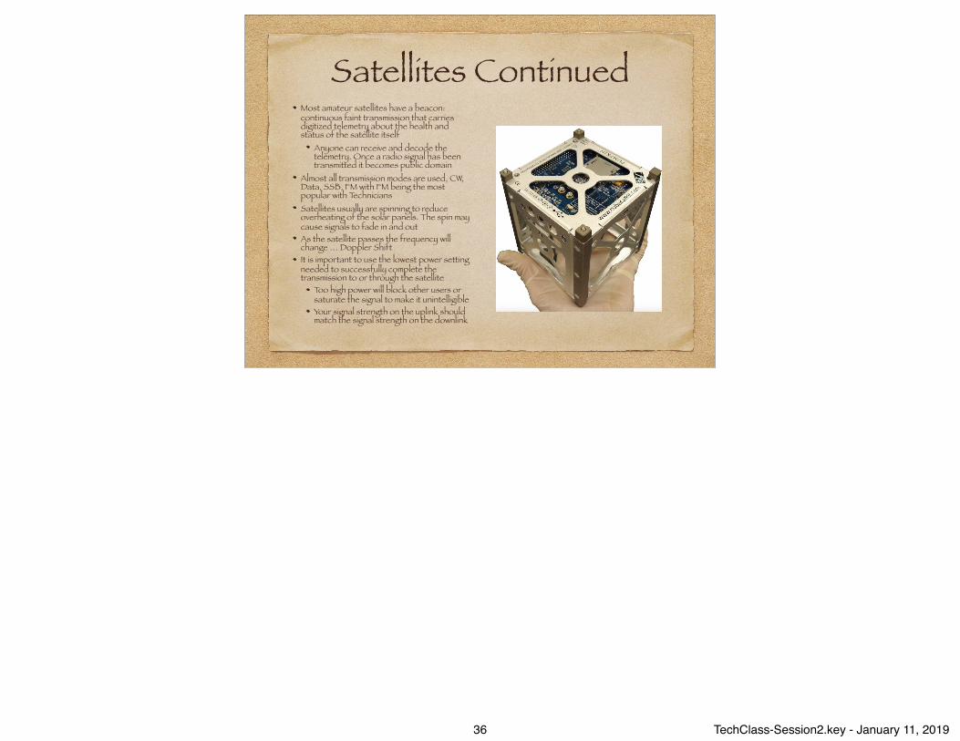
Satellites ContinuedMost amateur satellites have a beacon: continuous faint transmission that carries digitized telemetry about the health and status of the satellite itself
Anyone can receive and decode the telemetry. Once a radio signal has been transmitted it becomes public domain
Almost all transmission modes are used, CW, Data, SSB, FM with FM being the most popular with Technicians Satellites usually are spinning to reduce overheating of the solar panels. The spin may cause signals to fade in and out As the satellite passes the frequency will change … Doppler Shift It is important to use the lowest power setting needed to successfully complete the transmission to or through the satellite
Too high power will block other users or saturate the signal to make it unintelligible Your signal strength on the uplink should match the signal strength on the downlink
36 TechClass-Session2.key - January 11, 2019

And Finally, Space Stations ModesMost amateur radio satellites operate as “repeaters” … receiving a signal on one frequency and transmitting it simultaneously on another. Since there is limited space and power, the input frequency (uplink) is on one band and the output frequency (downlink) is on a different band The “mode” of the satellite indicates where the uplink and downlink are located. For instance, Mode U/V means uplink on the 70cm band and downlink on the 2meter band
Band Freq Range ModeHF 21-3o MHz H
VHF 144-148 MHz VUHF 435-438 MHz U
L band 1.26-1.27 GHz LS band 2.4-2.45 GHz SC band 5.8 GHz CX band 10.4 GHz XK band 24 GHz K
37 TechClass-Session2.key - January 11, 2019

A Satellite Contact Video
https://www.youtube.com/watch?v=XCdvCbjK_zo&t=81s
SO-50
38 TechClass-Session2.key - January 11, 2019

Digital Communications
39 TechClass-Session2.key - January 11, 2019

Digital CommunicationsThe original digital mode is CW (international morse code)
CW frequencies are from 50.0-40.1 MHz (10 meter band) and 144.0-144.1 MHz (2 meter band) Many hams us an electronic keyer when sending CW
A computer is used to generate and decode many other digital modes
The computer’s sound card is used to send audio to the radio’s microphone input, generate the PTT signal, and converts audio from the radio’s speaker output into digital form The physical connection from the radio is to the computer’s microphone or line input
40 TechClass-Session2.key - January 11, 2019
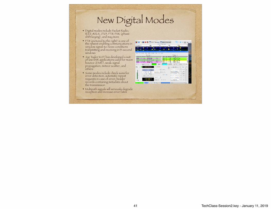
New Digital ModesDigital modes include Packet Radio, IEEE 802.11, JT65, FT8, PSK (phase shift keying), and may more FT8 (pictured to the right) is one of the newest enabling communications in very low signal-to-noise conditions transmitting and receiving in 15-second windows Joe Taylor K1JT has developed a suit of low SNR applications used for moon bounce (EME), weak-signal propagation, meteor scatter, and others Some modes include check sums for error detection, automatic repeat requests in case of error, header records containing metadata about the transmission Multipath signals will seriously degrade reception and increase error rates
41 TechClass-Session2.key - January 11, 2019

Automatic Packet Reporting System
APRS is an application capable of providing real-time tactical digital communications together with a map showing the location of stations
Requires a GPS receiver to provide position information to the transmitting application
Popular mobile text messaging application Many amateur weather stations use APRS to send their weather information to various weather data systems https://aprs.fi/#!addr=salt%20lake%20city%2C%20ut
42 TechClass-Session2.key - January 11, 2019

Other RF Digital ModesDigital Mobile Radio (DMR)
Two “time multiplexed” conversations on a 12.5 kHz channel Users connect to “talkgroups” which are conference rooms for like interests Inexpensive cost to play
D-Star Developed in Japan, supported by ICOM, Kenwood, and Elecraft Has very fast data transfer capability
System Fusion Developed by Yaesu and proprietary to Yaesu Growing in popularity
DMR, D-Star, and System Fusion are all incompatible with each other
43 TechClass-Session2.key - January 11, 2019
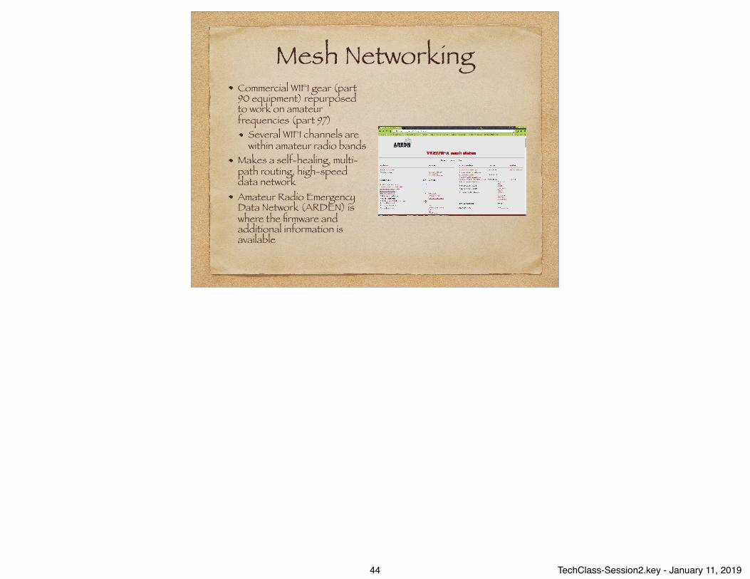
Mesh NetworkingCommercial WIFI gear (part 90 equipment) repurposed to work on amateur frequencies (part 97)
Several WIFI channels are within amateur radio bands
Makes a self-healing, multi-path routing, high-speed data network Amateur Radio Emergency Data Network (ARDEN) is where the firmware and additional information is available
44 TechClass-Session2.key - January 11, 2019
Some Other Digital Mode Information
PSK (phase shift keying) is a very popular keyboard to keyboard protocol as well as the ability to transfer files IRLP (internet radio linking project) is a technique to connect amateur radio systems, such as repeaters, using Voice Over Internet Protocol (VOIP). A popular IRLP repeater in our area is on 449.425(-) connected to the Western Reflector
DTMF (dual-tone multi-frequency) tones, similar to the touch tones on a phone) tones are used to connect and disconnect reflectors
Echolink is another VOIP system. There are Echolink applications that can run on your laptop or smart phone. Registration is required before using Echolink (to prove you are a licensed amateur). There are online services, printed directories, and subscription services to find repeaters and VOIP services
45 TechClass-Session2.key - January 11, 2019

And Finally, Amateur TVSlow scan tv as well as fast scan systems are available
Analog only at the moment. Hams are working on a non-patented digital codec
NTSC is the standard for fast scan color analog signals Typically used on the 70cm band and higher frequencies. Fast scan tv has a bandwidth of about 6 MHz (that’s why they’re on the higher frequencies!)
46 TechClass-Session2.key - January 11, 2019

That’s All for Today1
47 TechClass-Session2.key - January 11, 2019

48 TechClass-Session2.key - January 11, 2019