amerex instruments, inc. no. po2g-oo4-a hirayama - autoclave · introduction..this manual was...
TRANSCRIPT

Amerex Instruments, Inc.No. PO2G-OO4-A
HIRAYAMA
.IHICLAVE[
HV-25
HV-50
HV-85
HV-110
SERVICE MANUAL
P.o. Box 787, Lafayette, California 94549 .(925) 299-0743 .FAX: (925) 299-0745E-mail: [email protected] .Web: www.amerexinst.com
ru. ,
Introduction
..This manual was created to support smooth service of the HV autoclave series (HV-25, 50,
85'and 110). Use the manual as a reference in addition to the operation manual.
.Some tools are required (screw drivers, digital multimeter, and clamp meter) whenreplacing and making adjustment. Also, required tools are stated for particular works.
(1) No part of this document may be reproduced without permission.
(2) The contents of this document are subject to change without notice.
(3) This document has been carefully compiled. If you have any questions or requireinformation not covered in the manual, please contact:
Amerex Instruments, Inc.P.o. Box 787Lafayette, CA 94549U.S.A.Tel: (925) 299-0743Fax: (925) 299-0745E-mail: [email protected]
I
Read Carefully Before Usina -
.In this manual the following headings are applied to items to which great attention should be given:
& WARNING: Precaution indicating an imminent dangerous situation which if"& not avoided may lead to death or serious injury.
'CAUTION: Precaution indicating a dangerous situation which if not(j'\ .av~ided ~ay lead to moderate or slight injury.V IMPORTANT. Indicates Items you are strongly advised to obey.
& WARNING:
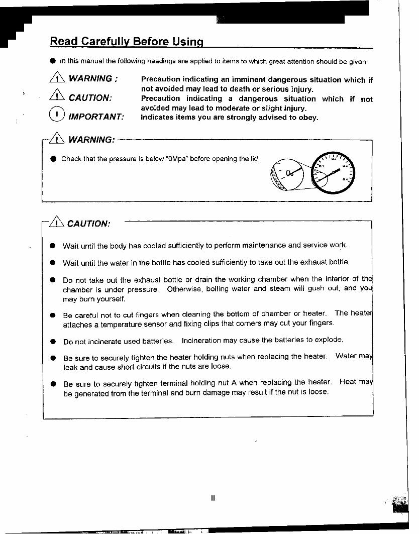
.Check that the pressure is below "OMpa" before opening the lid.
& CAUTION:
.Wait until the body has cooled sufficiently to perform maintenance and service work.
.Wait until the water in the bottle has cooled sufficiently to take out the exhaust bottle.
.Do not take out the exhaust bottle or drain the working chamber when the interior of thchamber is under pressure. Otherwise, boiling water and steam will gush out, and yo
may burn yourself.
.Be careful not to cut fingers when cleaning the bottom of chamber or heater. The heate
attaches a temperature sensor and fixing clips that corners may cut your fingers.
.Do not incinerate used batteries. Incineration may cause the batteries to explode.
.Be sure to securely tighten the heater holding nuts when replacing the heater. Water ma
leak and cause short circuits if the nuts are loose.
.Be sure to securely tighten terminal holding nut A when replacing the heater. Heat ma
be generated from the terminal and burn damage may result if the nut is loose.
II
How to Read this Manual
This manual consists of the following sections covering the information required for propermaintenance of the HV-25/50/85/11 0 autoclaves.
Chapter 1. Maintenance and Adjustment
This section describes the maintenance procedures for the unit as well as the methods for
replacing and adjusting the main parts.
Chapter 2. Troubleshooting Chart
This section describes the items to check and measures to take when a problem occurs.
Chapter 3. Product Description
This section describes the operations and internal structural parts of the product.
Chapter 4. Operation Check Procedure
This section describes the method for checking the operation of electrical parts using the check
programs.
Chapter 5. Main Parts List
The code numbers for the main pats are listed in the table here.
III
I

--
Contents
Chapter 1. Maintenance and Adjustment ""'.".' 1
1. Draining Water from the Exhaust Bottle ".""" ...12. Draining the Chamber. ".. 23. Cleaning the Chamber "" ,.".,..,.34. Cleaning the Body 35. Cleaning the Cooling Unit Filter " ".' ,..,..46. Lid Gasket Replacement '.""..' " " 57. Backup Battery Replacement '."...' '.'...""...68. Solid State Relay (SSR) Replacement '."'..."' 79. ROM Replacement 710. Heater Replacement 911. Temperature Control Sensor Replacement 1012. Floating Sensor (Option) Replacement 1113. Motor Replacement 1214. Exhaust Valve Replacement '...'.""' 13
15. Display Board Replacement 1416. Exhaust Valve Adjustment "..".'.."'...' 16
17. Alarm Volume Adjustment 1718. Switchboard Replacement "".".'." 17
Chapter 2. Troubleshooting Chart ' 18
1. Error Detection (Alarms)."'.".'.""".'."".""""""""""' 182. Early Trouble Shooting , , 20
3. Trouble Shooting 23
Chapter 3. Product Description 25
Error Monitoring Charts , "'.""""."-~" "..'."."" 26External Appearance , 30
Assembly Diagrams 31Detailed Display and Operation Switch Diagram .".,.,."."."",.."""." ,.., "".,. 35
Switchboard Diagram 36Exhaust Valve Area Diagram...' '.'..' ".'.." " 36
Solenoid Area Diagram 37Optional Accessories Diagrams '."' '...""..'..'.'.'." '..' 38
Piping Diagram 39:' Wiring Diagram ,..,.,.,.,.., ,.", , 40
Connector Table , 41
IV
, "",""
Chapter 4. Operation Check Procedure """""'.'.,.43
1. Check Program Outline 43
2. Check Program Startup : 443. Check Programs " "'..' " " '.""' ' '...".':'..." ' ' 45
Reference Table for Floating Sensor and Temperature Control Sensor 50Pressure Sensor Reference Table "..., "...,."..,.""",..",..,.,.""",.,.., 52
V
~ , ., ,
Chapter 1. Maintenance and Adjustment
&CAUTION:.Wait until the body has cooled sufficiently before performing maintenance and adjustment.
.Perform maintenance and adjustment after turning the power switch off.
1. Draining Water from the Exhaust Bottle
Since the water level in the exhaust bottle increases with continued operation, water must be
drained using the procedure below when water reaches the HIGH level.
ill CA ur/ON:.Wait until the water in the bottle has cooled sufficiently to take out the exhaust bottle.
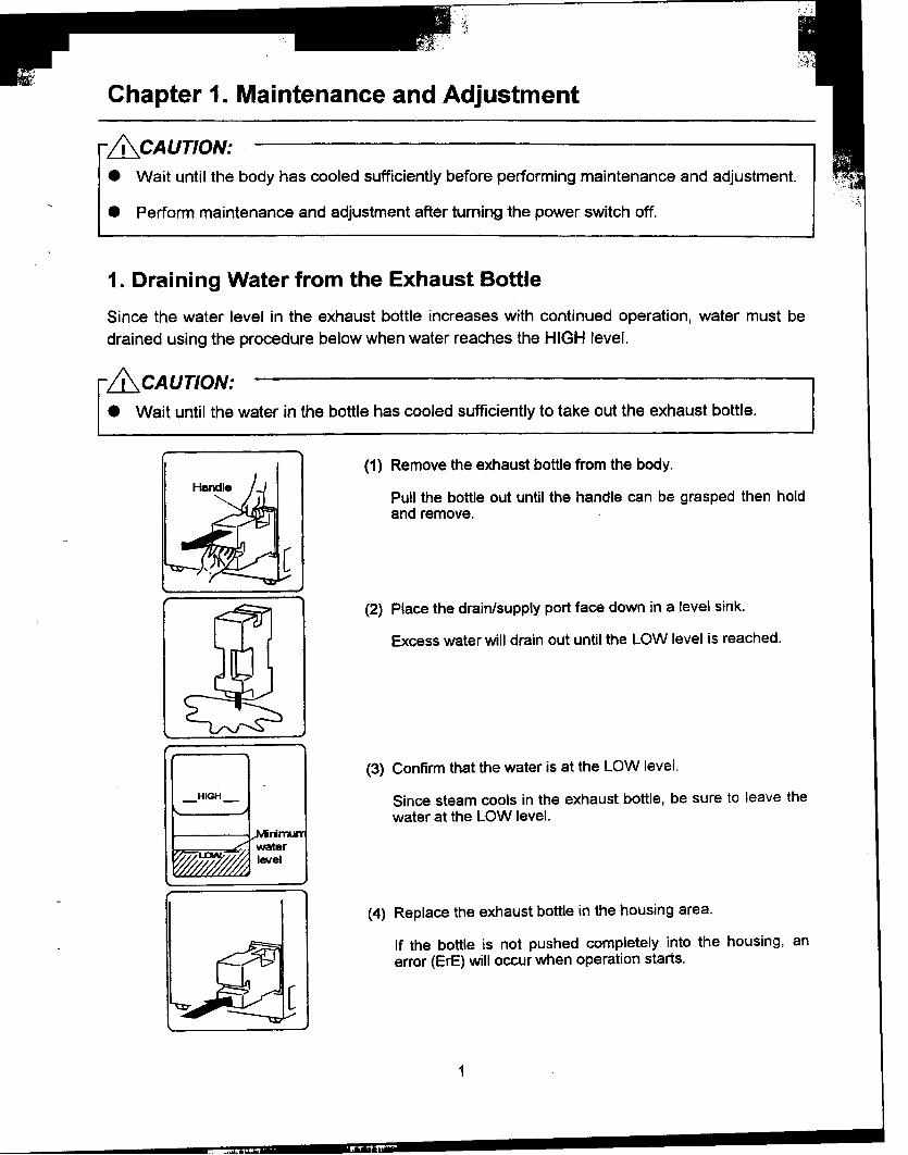
(1) Remove the exhaust bottle from the body.
Pull the bottle out until the handle can be grasped then holdand remove.
(2) Place the drain/supply port face down in a level sink.
Excess water will drain out until the LOW level is reached.
(3) Confirm that the water is at the LOW level.
_HIGH- Since steam cools in the exhaust bottle, be sure to leave thewater at the LOW level.
(4) Replace the exhaust bottle in the housing area.
If the bottle is not pushed completely into the housing, anerror (ErE) will occur when operation starts.
1
..
2. Draining the Chamber I
Drain water using the following procedure after confirming that the inside of the chamber has
cooled sufficiently.
& CAUTION:.Do not unload the exhaust bottle or drain the chamber when the chamber is under pressure.
Boiling water or steam may gush out causing bums.
(1) Open the lid.
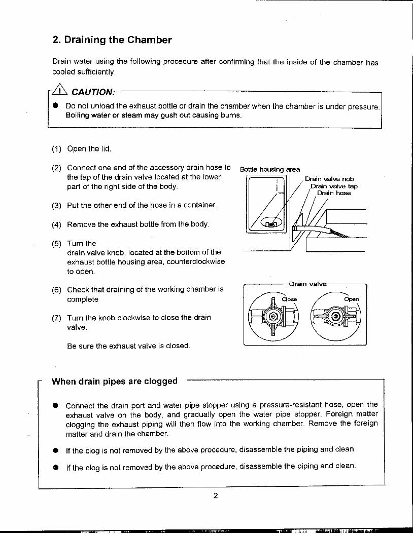
(2) Connect one end of the accessory drain hose to Bottle housing areathe tap of the drain valve located at the lower Or-ain valve nabpart of the right side of the body. Drain valve tapk Drai n hose
(3) Put the other end of the hose in a container.
(4) Remove the exhaust bottle from the body.
(5) Turn thedrain valve knob, located at the bottom of theexhaust bottle housing area, counterclockwise
to open.
Drain valve(6) Check that draining of the working chamber is
complete.
(7) Turn the knob clockwise to close the drain
valve.
Be sure the exhaust valve is closed.
When drain pipes are clogged
.Connect the drain port and water pipe stopper using a pressure-resistant hose, open theexhaust valve on the body. and gradually open the water pipe stopper. Foreign matterclogging the exhaust piping will then flow into the working chamber. Remove the foreign
matter and drain the chamber.
.If the clog is not removed by the above procedure, disassemble the piping and clean.
.If the clog is not removed by the above procedure, disassemble the piping and clean.
2
'"' ~li.1

3. Cleaning the Chamber
& CA UTION:.The heater is provided with a temperature sensor with clips. Be careful not to hurt your
fingers when cleaning.
I .
(1) Remove the heater cover to see if the bo~to~ of aterthe chamber or the surface of the heater IS dirty.After draining the chamber, clean these areas witha soft brush or the like while applying water andkeeping the drain valve open.
(2) Reattach the fixing clip of the temperature sensorif it has come off or is loose. Attach the cl ip so thatthe temperature sensor comes into close contact
.T en-perature sensorwith the heater. Fi>ong dip
4. Cleaning the Body
0 IMPORTANT:.Do not use benzine or thinner to clean the body. Also, make sure that volatile substances
such as insecticides do not come into contact with the body as these may cause
deterioration and stripping of the paint.
(1) Gently wipe stains with a soft cloth. To remove stubborn stains, wipe with a cloth soaked insolution of neutral detergent. Wipe off any remaining moisture with a dry cloth.
3
..

5. Cleaning the Cooling Unit Filter (For Cooling Unit option only)
An air filter is attached within the cooling unit. Clean the fan once a year according to the
following procedure.
Fan case(1) Remove the screws holding the fan case
and remove the fan case.
The filter is mounted inside the fan case mom -~
(2) Remove the filter holder screws and I!! -
remove the filter. ~~~
(3) Soak and gently wash the filter in neutral Fan case holding screws(2)detergent diluted in water.
Riter holder screws(4)
Avoid volatile detergents as these may <8_.Jcause discoloration or deformation. ..-'--
Riter holder(4) Sufficiently dry the filter. <8-.
.-.~
(5) Reattach the filter in the filter case.Riter
Replace the filter if flawed or broken.
(6) Match the protruding part of the fan casewith the cutout part of the base plate andsecure with the holding screws. omm j mam
moom Protrusion YFan case holding screws
4
,"" "i
6. Lid Gasket Replacement
.Lid gasket with a whitened edge may cause steam leakage. Replace the lid gasket,
if moistened with neutral detergent diluted with water, and wipe off the stains with it.
Wipe off any moisture with a dry cloth.
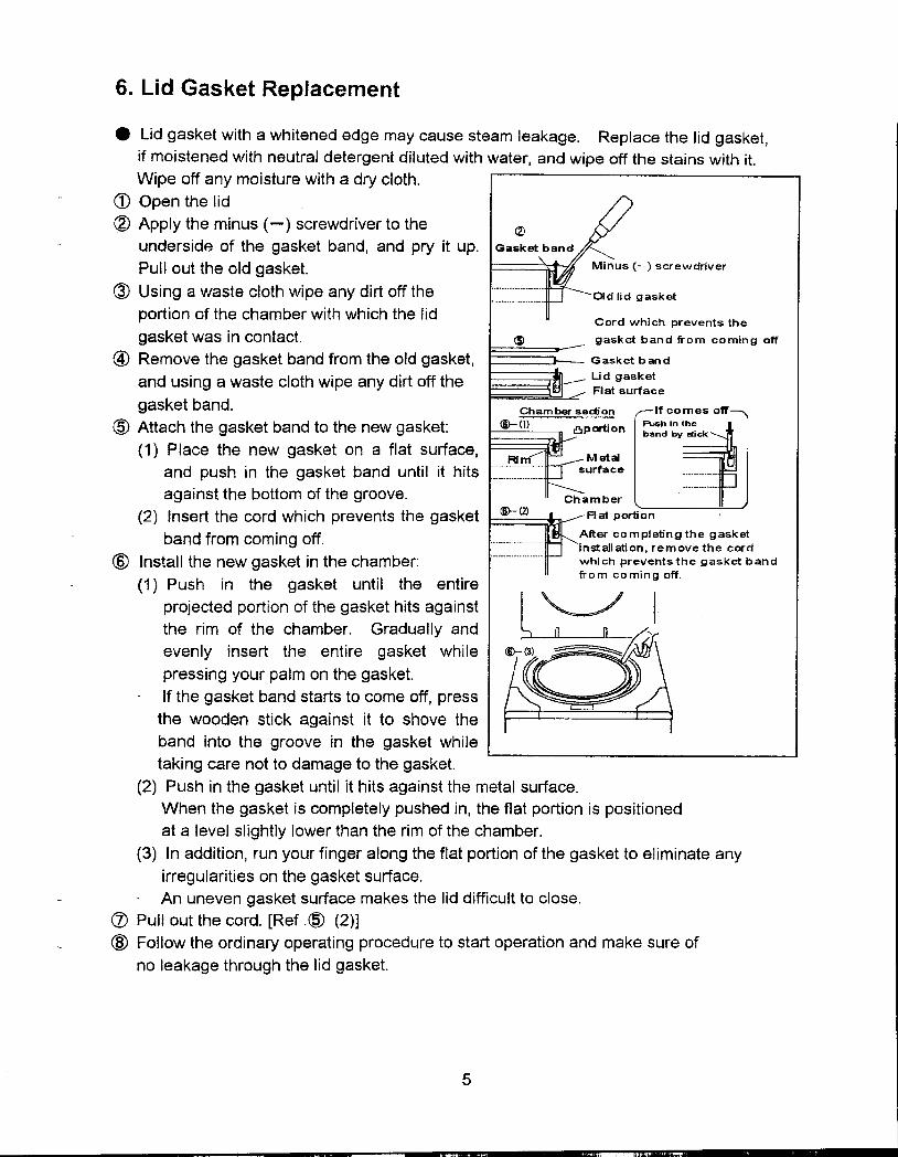
CD Open the lid
~ Apply the minus (-) screwdriver to the (2)
underside of the gasket band, and pry it up. Gask
Pullout the old gasket. -) screwdriver
~ Using a waste cloth wipe any dirt off the , Old lid asket
g
portion of the chamber with which the lid C d h . h t thor w IC preven s e
gasket was in contact. (S) gasket band ti"om coming off
@ Remove the gasket band from the old gasket, Gasket band
and using a waste cloth wipe any dirt off the Lid gasket
Flat surface
gasket band. Chamber section If comes off
@Attachthegasketbandtothenewgasket: @-(1) 8P orti on :~~i~yt ~~Ck (1) P I ace the new gasket on a flat surface, Ai M et~
and push in the gasket band until it hits :::=:::::: surface against the bottom of the groove- Chamber (2) Insert the cord which prevents the gasket @-(2) Flat portion
band from coming off. ~fter co,mpletingthe gasket
Installation, remove the cord(§) Install the new gasket in the chamber: which prevents the gasket band
(1) Push in the gasket until the entire ti"om coming off.
projected portion of the gasket hits against I"",_~'/ I
the rim of the chamber. Gradually and aevenly insert the entire gasket while @-(3) ~~
pressing your palm on the gasket,
If the gasket band starts to come off, press
the wooden stick against it to shove the
band into the groove in the gasket while
taking care not to damage to the gasket,
(2) Push in the gasket until it hits against the metal surface-
When the gasket is completely pushed in, the flat portion is positioned
at a level slightly lower than the rim of the chamber.
(3) In addition, run your finger along the flat portion of the gasket to eliminate any
irregularities on the gasket surface.
An uneven gasket surface makes the lid difficult to close.
(Z) Pullout the cord. [Ref,~ (2)]
@ Follow the ordinary operating procedure to start operation and make sure of
no leakage through the lid gasket.
5
c , t;"..,_..,,-

7. Backup Battery Replacement
.When the CLOCK display flickers, replace the backup battery in accordance with the
following procedure.
& CAUTION:.Connecting the battery with its polarities reversed may cause heating, explosion or ignition.
.Do not dispose of used batteries in fire; they may explode.
CD Hold both the ends of the connector for the backup
battery between your fingers, and pull the wire
connector out of the switch board.
~ Remove the screw from the clamp.
<J) Attach the clamp to a new battery, and screw Screw
the clamp on the switch board.
@ Insert the battery connector to the control PCB, with
twist wires several times, with care of its correct
direction.
@ Correct the clock following the operation manual.
.When the correction of the clock is complete,
the CLOCK display goes out.
neda
6
'" '--~"'-"J,,--"j.c" """,oal-

~~f,~ ,'..;;~
8. Solid State Relay (SSR) Replacement
(1) Pullout the terminals from the solid state relay (SSR).
(2) Remove the SSR by unscrewing from the switchboard.
(3) Wipe off the trace of heat dissipating grease and dust
adhering to the switchboard in the vicinity of the screw
holes.
(4) Clean the flat surface of the new SSR, then apply heat
dissipating grease evenly on it. Flat ~urface
...Heat dissipating grease(5) Fit the SSR to the switchboard and plug In the
terminals.
Since the IN side of the SSR has +/- polarity, be
sure to connect in the original position.
9. ROM Replacement
CD IMPORTANT:.When replacing the ROM, use a special too M
to avoid damaging the control PCB or the
new ROM.
.The PCB or ROM can be damaged iftouched or brought into contact with peopleor clothing having a static electricity charge. 01
Touch a metal object or take othermea~ures to discharge static electricitybefore performing these operations.
(1) Follow the procedure below to remove theROM from the IC socket using a ROM puller
...The hCXJks should catch at both ends.Push the trigger on the puller lO open IC ..J, t (-~~~"L-so,-",e -~r
the hooks. ~ '--_J]//~~ ~ L_,-
.Set the ends of the hooks to catch on R~ j- ~
the bottom of the ROM.
.Pull the trigger to remove the ROM.
7
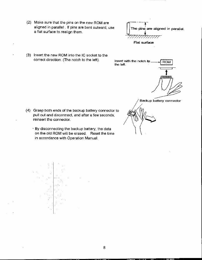
(2) M~ke s~re that the pin~ on the new ROM are[f ---1- aligned In parallel. If pins are bent outward, use The pins are aligned in parallel.
a flat sL..,,'1ace to realign them. ___1-
//////////////
Flat surface
{3) Insert the new ROM into the IC socket to thecorrect direction. (The notch to the left). Insert wth the notd"l to_rROM--'
the left.. (-;-~~~::.JI I
t
p battery connector
(4) Grasp both ends of the backup battery connector topullout and disconnect, and after a few seconds,reinsert 1he connector.
.By disconnecting the backup battery, the dataon the old ROM will be erased. Reset the timein accordance with Operation Manual.
8
.'"" ,.

10. Heater Replacement
&CA UTION:
.Be sure to securely tighten the heater holding nuts when replacing the heater. Water mayleak and cause short circuits if the nuts are loose.
.Be sure to securely tighten terminal holding nut A when replacing the heater. Heat may begenerated from the terminal and burn damage may result if the nut is loose.
.Required tools
.Monkey wrench (with maximum opening width of 23mm or more)
.Spanner (7mm span for the heaters of HV-25/50; and 8mm for HV-85/110)
Removina the old heater
(1) Open the lid and turn the power switch off. Temperature sensor for ~ack-ofwater preventiondeVIce
Ga :;~~.~~~;~~~~~eater 1\
(2) Drain water from the chamber. U
Gasket(3) Remove the blank plate (or the optional ChalTDer .
cooling unit) fitted on the rear panel. ~q~ Fixin cli
Ra~\NaSher g p (4) Remove the t~mperature se.n~or (f~r lack-of- Ring tenrinal Heater holding nut
water prevention) from the fixing clips on the TerTrinal holding nut 8heater. (The fixing clips for HV-25L/50L are TerTrinal holding nut Asmall pipes welded to the heater, andthose for HV-85L/11 OL are of flexible spring.)
(5) Loosen the terminal holding nut A andremove the ring terminal.
(6) Remove the heater holding nuts.II Heater
(7) Remove the heater from the chamber. i I\~*;~=~=:;
(8) Remove any scale or stains from f/~~:.::=~~!~i~~::~the area around the heater fixing holes. "li Gasket
~=-=-~ Heater fi:ng_h~leS
Fixina the new heater """"""~ ~""~ ~ Flat washer
(9) Remove the heater holding nuts and "'~flat washers attached to the new heater. Heater holding nut
9
" , , ...'""1 "","'11"'"
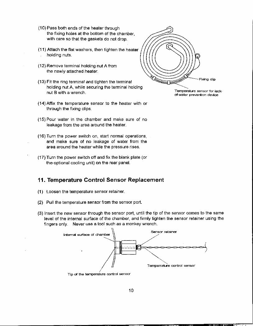
(10) Pass both ends of the heater through
the fixing holes at the bottom of the chamber,
with care so that the gaskets do not drop.
(11) Attach the flat washers, then tighten the heater
holding nuts.
(12) Remove terminal holding nut A fromthe newly attached heater.
(13) Fit the ring terminal and tighten the terminal Fi>dng dip
holding nut A, while securing the terminal holdingnut B with a wrench. Temperature sensor for.la~
of-water prevention deVIce
(14) Affix the temperature sensor to the heater with or
through the fixing clips.
(15) Pour water in the chamber and make sure of no
leakage from the area around the heater.
(16) Turn the power switch on, start normal operations,
and make sure of no leakage of water from thearea around the heater while the pressure rises.
(17) Turn the power switch off and fix the blank plate (or
the optional cooling unit) on the rear panel.
11. Temperature Control Sensor Replacement
(1) Loosen the temperature sensor retainer.
(2) Pull the temperature sensor from the sensor port.
(3) Insert the new sensor through the sensor port, until the tip of the sensor comes to the same
level of the internal surface of the chamber, and firmly tighten the sensor retainer using thefingers only. Never use a tool such as a monkey wrench.
or retainerI ntema/ surface of dlamber
.~T enlJerrature control sensor
Tip of the temperature a:>ntrol sensor
10
c.~ .

12. Floating Sensor (Option) Replacement
.Required tools
.Monkey wrench (with maximum opening width of 24mm or more)
(1) Pull the cord spring down and remove from Inside of the d1an'ber
the cord cover. Cord rover
(2) Remove the cord from the cord cover groove.
(3) Loosen the sensor retainer and remove the Cord spring (1)
sensor from the joint.
(4) Remove the sensor joint from the T -joint. Se
(5) Pull the sensor out from the T -joint hole.
(6) Insert the new floating sensor into the chamber Groove
through the T -joint hole and pull inward to the
length shown below.
HV-25L: ~450mm, HV-50L & HL-85L: ~600mm, HV-110L: ~780mm
(7) Attach the sensor joint to the T -joint.
(8) Attach the sensor gasket, sensor washer, and sensor retainer to the sensor joint. (firmly
tighten the sensor retainer using the fingers only. Never use a tool such as a monkey
wrench.)
Roating sensor Sensor gasket Sensor retainer
int Sensor joint Sensor washer
(9) Pass the cord downward into the cord cover groove, and then, insert the cord spring intothe cord cover groove.
11
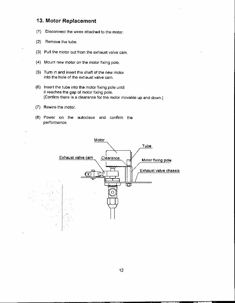
13. Motor Replacement
(1) Disconnect the wires attached to the motor.
(2) Remove the tube.
(3) Pull the motor out from the exhaust valve cam.
(4) Mount new motor on the motor fixing pole.
(5) Turn in and insert the shaft of the new motorinto the hole of the exhaust valve cam.
(6) Insert the tube into the motor fixing pole untilit reaches the gap of motor fixing pole.
[Confirm there is a clearance for the motor movable up and down.]
(7) Rewire the motor.
(8) Power on the autoclave and confirm the
performance.
Motor
Tube
Exhaust valve cam Motor fixing pole
Exhaust valve chassis
12
",. 'c, ,i
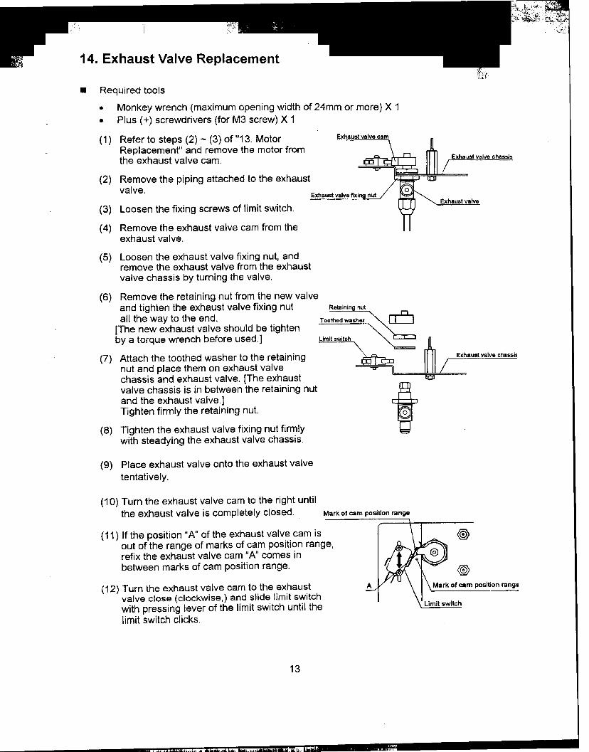
14. Exhaust Valve Replacement
.Required tools
.Monkey wrench (maximum opening width of 24mm or more) X 1
.Plus (+) screwdrivers (for M3 screw) X 1
(1) Refer to steps (2) -(3) of "13. Motor Exhaust
Replacement" and remove the motor fromthe exhaust valve cam. Exhauslvalve chassis
(2) Remove the piping attached to the exhaustvalve. Exhaust valve flJ(ing nul
(3) L th f.. f I.. t . h Exhaust valve oosen e Ixlng screws 0 Iml SWltc .
(4) Remove the exhaust valve cam from theexhaust valve.
(5) Loosen the exhaust valve fixing nut, andremove the exhaust valve from the exhaustvalve chassis by turning the valve.
(6) Remove the retaining nut from the new valveand tighten the exhaust valve fixing nut Retaining nulall the way to the end. TQQ:~:~::~~;~:::::~:~~:;~:)edwaSher ~
[The new exhaust valve should be tightenby a torque wrench before used.] ::::~-""~~:~~" """""~~~~-~.L=:""-",,..-imitSWitCh
(7) Attach the toothed washer to the retaining Exhaustvalv8 chass~
nut and place them on exhaust valvechassis and exhaust valve. [The exhaustvalve chassis is in between the retaining nut tand the exhaust valve.]Tighten firmly the retaining nut. 0
(8) Tighten the exhaust valve fixing nut firmlywith steadying the exhaust valve chassis.
(9) Place exhaust valve onto the exhaust valve
tentative Iy.
(10) Turn the exhaust valve cam to the right untilthe exhaust valve is completely closed. Mark of cam position range
(11) If the position "A" of the exhaust valve cam is @)out of the range of marks of cam position range,refix the exhaust valve cam "A" comes inbetween marks of cam position range. @>
(12) Turn the exhaust valve cam to the exhaust Mark of cam position range
valve close (clockwise,) and slide limit switchwith pressing lever of the limit switch until the 'tch
limit switch clicks.
13
" ",." , ,,:," .,. "C" w.

~:,~t~~7'::;;
(13) Refer to steps (4) -(6) of "13, Motor
Replacement" and fix the motor,
(14) Start operating with the normal procedure and make sure that steam does not come
out from the exhaust valve hose port while the chamber is pressurized. If steam
comes out too much, adjust the exhaust valve with reference to "16. Exhaust ValveAdjustment. "
15. Display Board Replacement.Required tools
.Plus ( + ) screwdrivers 2 (1 each for M5 and M3 screws)
.Vinyl adhesive tape
.Sealing tape (glass cloth impregnated with P.T.F.E.)
(1) Disconnect the connector from CN 1 ~on the control PCB.Bind the connector and the ribbon cable ...
together with vinyl adhesive tape so as
to facilitate passing through the duct hesive tape
(2) Open the lid and unscrew the lid bottom cover fixing screws.
(3) Peel the seals covering the holes for the lid cover fixing screws and unscrew them.
Ud cover fi
Ud bottom cover fixing screw (8)
uct
(4) Pass the ribbon cable of the display board through the duct and remove the lid cover,
(5) Peel the sealing tapes (PTFE impregnated glass cloth) of the protective plastic cover,
and remove the cover by unhooking from tapping screws.
Sealing tape Protective cover Tapping screw head~~~~~~~~~; /! --
0 !
;: II! I0 0 0I! I I
o! i;fJfJlIlIlIlIlIlIlIlI!fllll/Jfllllllllllllllllll~ i
14
" .oj , ~

-
(6) Remove the flexible cable (printed film) connected to the display board.
.Ie
Display Board
/Grasp the slider lad< and pull up
(7) Unscrew the 2 [REAR]-side tapping screws, and remove the display board.
(8) Loosen slightly (1 turn or 2) the 2 [FRONT]-side tapping screws.
(9) Push the display to [FRONT]-side. Put the new display board in contact with the holdingrods. Pass each of the 2 tapping screws on [REAR]-side, through a collar, a board holdingseat, a display board fixing hole and a flat washer (M4), and fix to the lid cover.
(10) Tighten the [FRONT]-side tapping screws.
Collar
r
Tapping scr
EA~J
Displayc:
Holding rod J
(11) Look at the display from outside of the lid cover and make sure that the character windowis aligned with the LED. If not aligned, loosen the tapping screws and realign.
(12)Connect the flexible cable to the connector of the display board.
Rexible cable
Slire-lockInsert the flexible cable and press the slide-lock
{13} Push the other end of the ribbon cable in between the display board and the lid cover.
(14) Put the tapping screw heads in the holes of the protective cover, and seal the two placesof the protective cover with the sealing tape, i.e. the ribbon cable outlet and the end on the
membrane switch side.
15

Sealing tape
~~~~("-;~;::;::-~:~~~~~~~~tect!ve ~ ~ TapPij9 screw head
;:;;;;;;;;;~;~~~~~;==~~ 1ii'.' .I .
push the ribbon ca~e in
(15) Bind the connector and ribbon cable together with vinyl adhesive tape, and pass them
through the duct.
(16) Fix the lid cover with the corresponding screws.
(17) Fix the lid bottom cover with the corresponding screws and seal the screw holes.
(18) Remove the vinyl adhesive tape [ref. the above (15)], and connect the connector to CN1
on the control PCB.
16. Exhaust Valve Adjustment
.Required tools
.Plus (+) screwdriver (for M3 screws)
(1) Refer to steps (2) -(3) of 1'13. Motor Replacement" and remove the motor from the exhaust
valve cam.
(2) Loosen the fixing screws of limit switch, and slide the limit switch to side "B".
(3) Turn the exhaust valve cam to the right by hand, and make the valve completely closed.
(4) If the position "A" of the exhaust valve cam is out of the range of marks of cam position
range, refix the exhaust valve cam "An comes in between marks of cam position range.
(5) Turn the exhaust valve cam to the exhaust valve close (clockwise,) and slide limit switch
with pressing lever of the limit switch until the limit switch clicks.
(6) Refer to steps (4) -(6) of '113. Motor Replacement" and fix the motor.
(7) Power on the autoclave and confirm the performance.
16
..",.
--
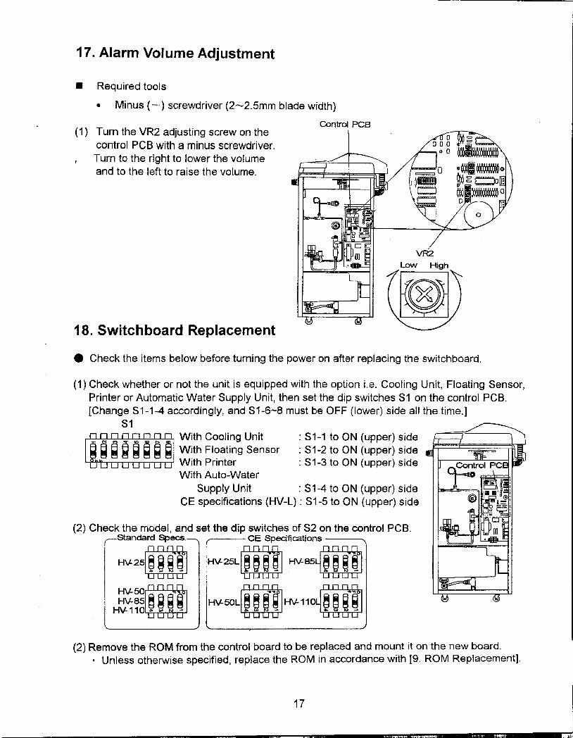
17. Alarm Volume Adjustment
.Required tools
.Minus (-) screwdriver (2--2.5mm blade width)
Control PCB(1) Turn the VR2 adjusting screw on the
control PCB with a minus screwdriver.
I Turn to the right to lower the volume
and to the left to raise the volume.
18. Switchboard Replacement
.Check the items below before turning the power on after replacing the switchboard.
(1) Check whether or not the unit is equipped with the option i.e. Cooling Unit, Floating Sensor,
Printer or Automatic Water Supply Unit, then set the dip switches S1 on the control PCB.
[Change S1-1-4 accordingly, and S1-6-8 must be OFF (lower) side all the time.]
S1W inO'" With Cooling Unit: S1-1 to ON (upper) side
~ ~ ~ @ ~ @ ~ ~ With Floating Sensor: S1-2 to ON (upper) side
With Printer : S1-3 to ON (upper) side
With Auto-Water
Supply Unit : S1-4 to ON (upper) side
CE specifications (HV-L) : S1-5 to ON (upper) side
(2) Check the model, and set the dip switches of S2 on the control PCB.Standard Specs. CE Specifications
H\l'24:i:i:i] HV-25LD HV'85m
~a:im H\l'50LD HV-11@
(2) Remove the ROM from the control board to be replaced and mount it on the new board.
.Unless otherwise specified, replace the ROM in accordance with [9. ROM Replacement].
17
I
"c._- m~"."".'._.'~'""""" "."c"i
Chapter 2. Troubleshooting Chart
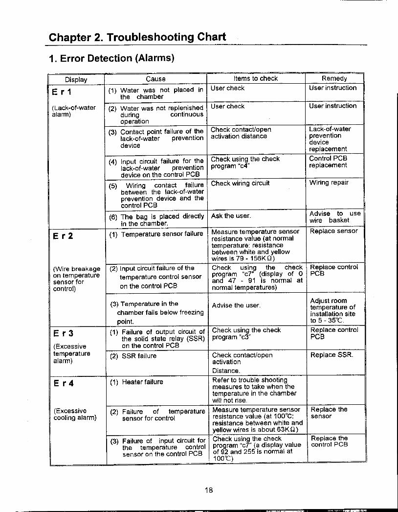
1. Error Detection (Alarms)
Display Cause Items to check Remedy
E r 1 (1) Water was not placed in User check User instruction
the chamber
(Lack-of-water (2) Water was not replenished User check User instruction
alarm) during continuousoperation
(3) Contact point failure of the Ch~ck.cont~ct/open Lack-of-waterlack-of-water prevention activation distance preventiondevice device
replacement
(4) Input circuit failure for the Check using the check Control PCBlack-of-water prevention program "c4" replacement
device on the control PCB
(5) Wiring contact failure Check wiring circuit Wiring repair
between the lack-of-waterprevention device and thecontrol PCB
(6) The bag is placed directly Ask the user. Advise to usein the chamber. wire basket
-E r 2 (1) Temperature sensor failure Me.asure temperature sensor Replace sensor
resistance value (at normal
temperature: resistancebetween white and yellowwires is 79 -156KO)
(Wire breakage (2) Input circuit failure of the Check using the check Replace controlon temperature temperature control sensor program "c7" (display of 0 PCBsensor for and 47 -91 is normal atcontrol) on the control PCB normal temperatures)
(3) Temperature in the Advise the user. Adjust room
chamber falls below freezing ~emper~ture .of. t Installation site
poln .to 5 -35°C.
E r 3 (1) Failure of output circuit of Check using the check Replace controlthe solid state relay (SSR) program "c3" PCB
(Excessive on the control PCBtemperature .alarm) (2) SSR failure Ch.eck.contact/open Replace SSR.
activation
Distance.
E r 4 (1) Heater failure Refer to trouble shootingmeasures to take when the
-temperature in the chamberwill not rise.
(Ex~essive (2) Failure of temperature Measure temperature sensor Replace the-cooling alarm) sensor for control resistance value (at 100°C: sensor
resistance between white andyellow wires is about 63KO)
(3) Failure of input circuit for Check using the check Replace thethe temperature control program "cT' (a display value control PCBsensor on the control PCB of 92 and 255 is normal at
1 OO°C)
18
c,.. "",",",

Display Cause Items to check Remedy
E r 5 (1) Exhaust valve failure Refer to trouble shootingmeasures to take when theair in the chamber will notpurge
(Excessive (2) Pressure sensor failure Measure pressure sensor Replace thepressure alarm) output voltage (at O.12MPa, pressure sensor
terminal No.4 of connectorCN6 should be aboutDC+2.1V)
(3) Input circuit failure of the Check using the check Replace thepressure sensor on the program "c11" (a display control PCBcontrol PCB value of "107" is normal at
O.12MPa)
(4) The bag is placed directly Ask the user A~vise to use'
th h b .wire basketIn e c am er
E r 6 (1) Lock plate is loosely fitted. Check.l«:>oseness of the lock Tighten theplate fixing screws screws
(Lid. (2) LSW2 limit switch is <;:h.eck I,oose,n.ess of LSW2 Tighten themalfunction loosely fitted. limIt switch fixing screws, screws
alarm)(3) LSW2 limit switch Check contact/open Replace the limit
failure activation distance switch
(4) Failure of input circuit for Check using the check Replace theLSW2 limit switch on the program "c4" control PCBcontrol PCB
E r 7 (1) LSW3 limit switch is Check looseness of the limit Tighten theloosely fitted. switch LSW3 fixing screws. screws
(Exhaus~ valve (2) LSW3 limit switch Ch,eck.cont.act/open Replace the limitmalfunction failure activation distance switch
alarm)(3) Failure of input circuit for Check using the check Replace the
LSW3 limit switch on the program "c4" control PCBcontrol PCB
(4) Failure of the motor or 2X Check using the check Replace therelay. program "c3" failed parts
E r 8 (1) The water tap is not open User check User instruction
(Auto- wa~er (2) Failure of SV1 solenoid or Check using the check Replacesupply Unit 2X relay. program "c5" defective partsmal-function alarm)
(3) Failure of FSW water level Check contact/open Replace waterdetector activation distance level detector
(4) Failure of input circuit for Check using check program Replace theFSW water level detector "c5" control PCBon the control PCB
E r 9 Same as "Er4."
(Sterilizationheater mal-function alarm)
19 J
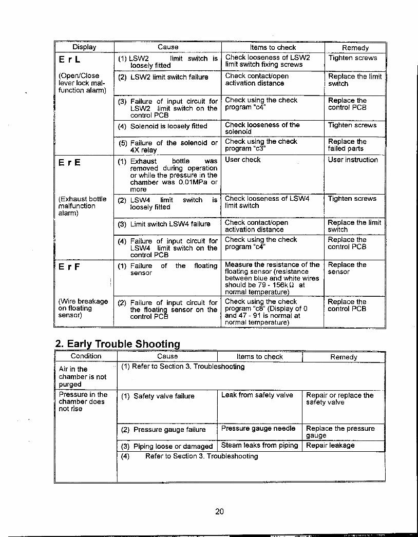
Display Cause Items to check Remedy
E r L (1) LSW2 limit switch is Check looseness of LSW2 Tighten screwsloosely fitted limit switch fixing screws
(Open/Close (2) LSW2 limit switch failure Check contact/open Replace the limit
lever lock mal- activation distance switch
function alarm)
(3) Failure of input circuit for Check using the check Replace the
LSW2 limit switch on the program "c4" control PCB
control PCB
(4) Solenoid is loosely fitted Check)ooseness of the Tighten screwssolenoid
(5) Failure of the solenoid or Check using the check Replace the4X relay program "c3" failed parts
ErE (1) Exhaust bottle was User check User instruction
removed during operationor while the pressure in the
chamber was O.O1MPa or
more
(Exhaust bottle (2) LSW4 limit switch is Check looseness of LSW4 Tighten screws
malfunction loosely fitted limit switch
alarm)(3) Limit switch LSW4 failure Check contact/open Replace the limit
activation distance switch
(4) Failure of input circuit for Check using the check Replace the
LSW4 limit switch on the program "c4" control PCB
control PCB
E r F (1) Failure of the floating Mea~ure the resist~nce of the Replace thesensor floating sensor (resistance sensor
between blue and white wiresshould be 79 -156k I:); at
normal tern erature
(Wire b~eakage (2) Failure of input circuit for Check u~!ng" th~ check Replace theon floating the floating sensor on the program c8 (Display of 0 control PCB
sensor) control PCB and 47 -91 is normal atnormal temperature)
2. Earl Trouble ShootingCondition Cause Items to check Remedy
Air in the (1) Refer to Section 3. Troubleshooting
chamber is not
purged
Pressure in the (1) Safety valve failure Leak from safety valve Repair or replace thechamber does safety valve
not rise
(2) Pressure gauge failure Pressure gauge needle Replace the pressure
gauge(3) Piping loose or damaged Steam leaks from piping Repair leakage
(4) Refer to Section 3. Troubleshooting
20
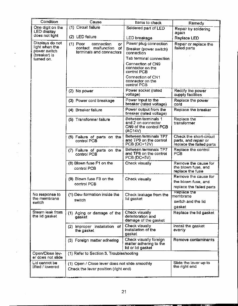
Condition Cause Items to check Remedy
One d~git on the (1) Circuit failure Soldered pari of LED Repair by solderingLED dlspl~y againdoes not light (2) LED failure LED breakage Replace LED
I;>isplays do not (1) Poor connection or Power plug connection Repair or replace thelight wheT! the cont~ct malfunction of Breaker (power switch) failed paris
-power swl,tch terminals and connectors connection(breaker) ISturned on. Tab terminal connection
Connection of CN9-connector on the
control PCB
Connection of CN 1connector on thecontrol PCB(2) No power Power socket'-(rated "'."'.. .-Rect.ity'th.e...pow.er ".'-""'-"-
voltage) supply facilities
(3) Power cord breakage Power input to the Replace the powerbreaker (rated voltage) cord
(4) Breaker failure Power output from the Replace the breakerbreaker (rated voltage)
(5) Transformer failure Between terminals 1 Replace theand 2 on connector transformerCN9 of the control PCB(AC14V)
(6) Failure of paris on the Between terminals TP7 Check the shori-circuitcontrol PCB and TP9 on the control parts, and repair or~ PCB (DC+12V) replace the failed paris
(7) Failure of paris on the Between terminals TP7 Replace the controlcontrol PCB and TP8 on the control PCB
I PCB (DC+5V)(8) Blown fuse F1 on the Check visually Remove the cause for
control PCB the blown fuse, andreplace the fuse
(9) BI f F3 th Ch k . II Remove the cause forown use on e ec vlsua y
t 1 PCB the blown fuse, andcon ro
replace the failed parts
No response to (1) Dew formation inside the ~heck leakage from the m~~~~~~~nethe membrane switch lid gasketswitch switch and the lid
gasketSteam leak from. (1) Aging or damage of the Check visually Replace the lid gasketthe lid gasket gasket deterioration and
damage of the gasket
(2) Improper installation of Check visually Install the gasketthe gasket installation of the evenly
gasket(3) Foretgn matter adhering Check visually foreign Remove contaminants
matter adhering to thelid or lid gasket
.Open/Close lev- (1) Refer to Section 3. Troubleshootinger does not slide
Lid cannot be (1) Open / Close lever does not slide smoothly Slide the lever up tolifted flowered Check the lever position (right end) the right end
21
"'"'"" .""'" ..,li
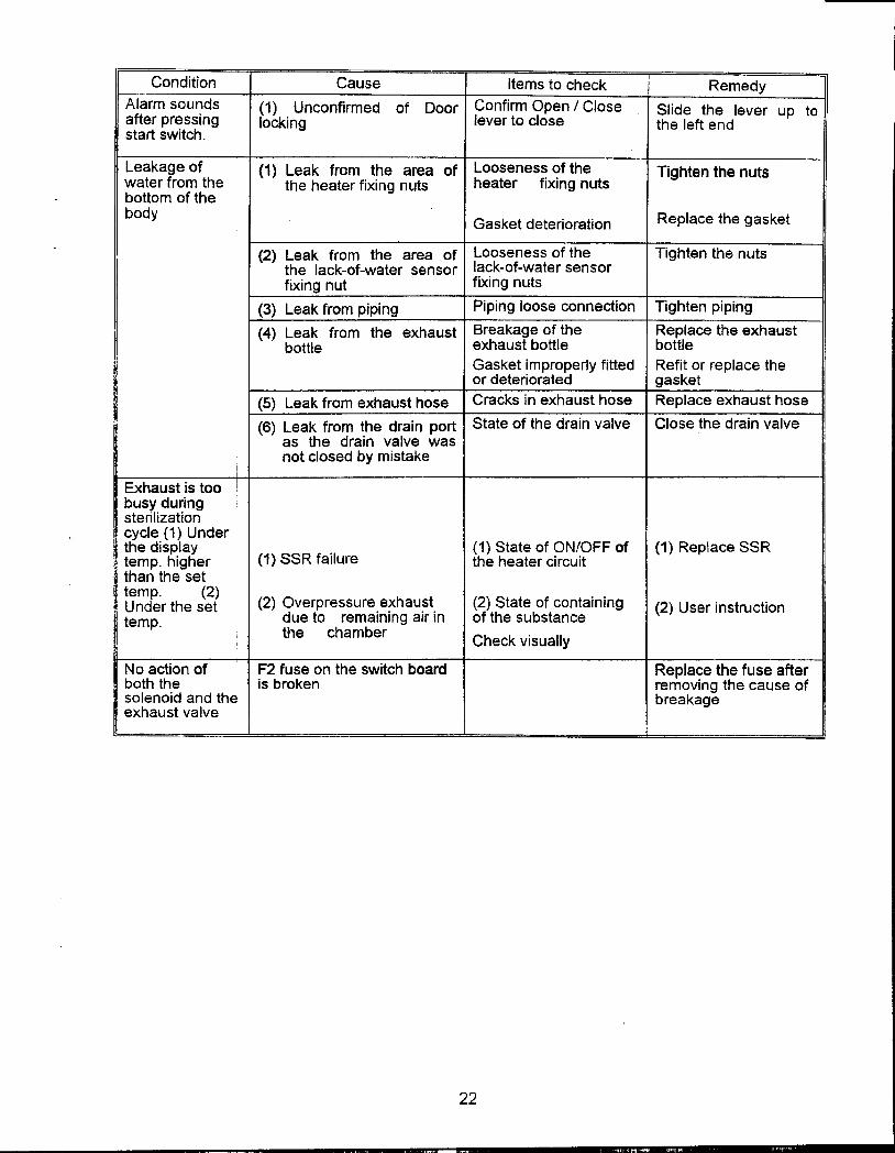
Condition Cause Items to check Remedy
Alarm sou~ds (1) Unconfirmed of Door Confirm Open / Close Slide the lever up toafter pr~sslng locking lever to close the left endstart switch.
Leakage of (1) Leak from the area of Loosenes~?f the Tighten the nutswater from the the heater fixing nuts heater fixing nuts
-bottom of thebody Gasket deterioration Replace the gasket
-(2) Leak from the area of Looseness of the Tighten the nutsthe lack-of-water sensor lack-of-water sensorfixing nut fixing nuts
(3) Leak from piping Piping loose connection Tighten piping
(4) Leak from the exhaust Breakage of the Replace the exhaustbottle exhaust bottle bottle
Gasket improperly fitted Refit or replace theor deteriorated gasket
(5) Leak from exhaust hose Cracks in exhaust hose Replace exhaust hose
(6) Leak from the drain port State of the drain valve Close the drain valveas the drain valve wasnot closed by mistake
Exhaust is too!busy duringsterilization
.cycle (1) Underthe display .(1) State of ON/OFF of (1) Replace SSRtemp. higher (1) SSR failure the heater circuitthan the settemp. (2) ( ..Under the set (2) Overpressure.e~hau.st. 2) State of contaIning (2) User instructiontemp. due to remaining air In of the substance
, the chamber Check visually
No action of F2 fuse on the switch board Replace the fuse afterboth the is broken removing the cause ofsolenoid and the breakageexhaust valve
22
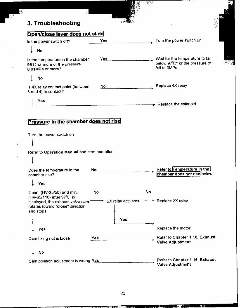
3. Troubleshooting
!Open/close lever does not slid~Is the power switch off? Yes ~ Turn the power switch on
t No
Is the temperature in the chamber Yes ~ Wait for the temperature to fall98°C or more or the pressure below 97°C* or the pressure toO.O1MPa or more? fall to OMPa
~ No
Is 4X relay contact point (between No ~ Replace 4X relay
3 and 4) in contact?
I Yesl ' g~ .Replace the solenoid
~ressure in the chamber does not ris~
Turn the power switch on
1Refer to Operation Manual and start operation
!Does the temperature in the No--,chamber rise?
1 Yes
3 min. (HV-25/50) or 6 min. No No(HV-85/110) after 97°C isdisplayed, the exhaust valve cam ~ 2X relay activates ~ Replace 2X relay
rotates toward !'close" direction ~and stops
1 Yes
Yes Replace the motor
Cam fixing nut is loose Yes ~ Refer to Chapter 1 16. Exhaust
Valve Adjustment
t No
Cam position adjustment is wrong Yes ~ Refer to Chapter 1 16. ExhaustValve Adjustment
23
, ,.c...,.., -, "'w ,..1 ~
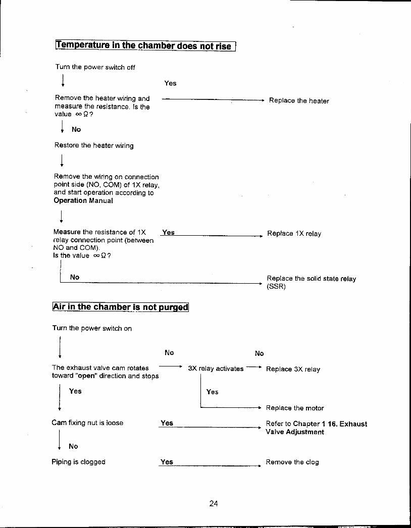
em erature in the chamber does not rise
Turn the power switch off
1 Yes
Remove the heater wiring and .Replace the heatermeasure the resistance. Is thevalue = Q?
t No
Restore the heater wiring
tRemove the wiring on connectionpoint side (NO, COM) of 1X relay,and start operation according toOperation Manual
tMeasure the resistance of 1X Yes .Replace 1X relayrelay connection point (betweenNO and COM).Is the value = Q?
I No .Replace the solid state relay
(SSR)
lAir in the chamber is not purged!
Turn the power switch on
j No No
The exhaust valve cam rotates .3X relay activates --+ Replace 3X relay
toward "open" direction and stops L1 Yes Yes
Replace the motor
Cam fixing nut is loose Yes Refer to Chapter 1 16. Exhaust
1 .Valve Adjustment
No
Piping is clogged Yes .Remove the clog
24
'"" "," '""",
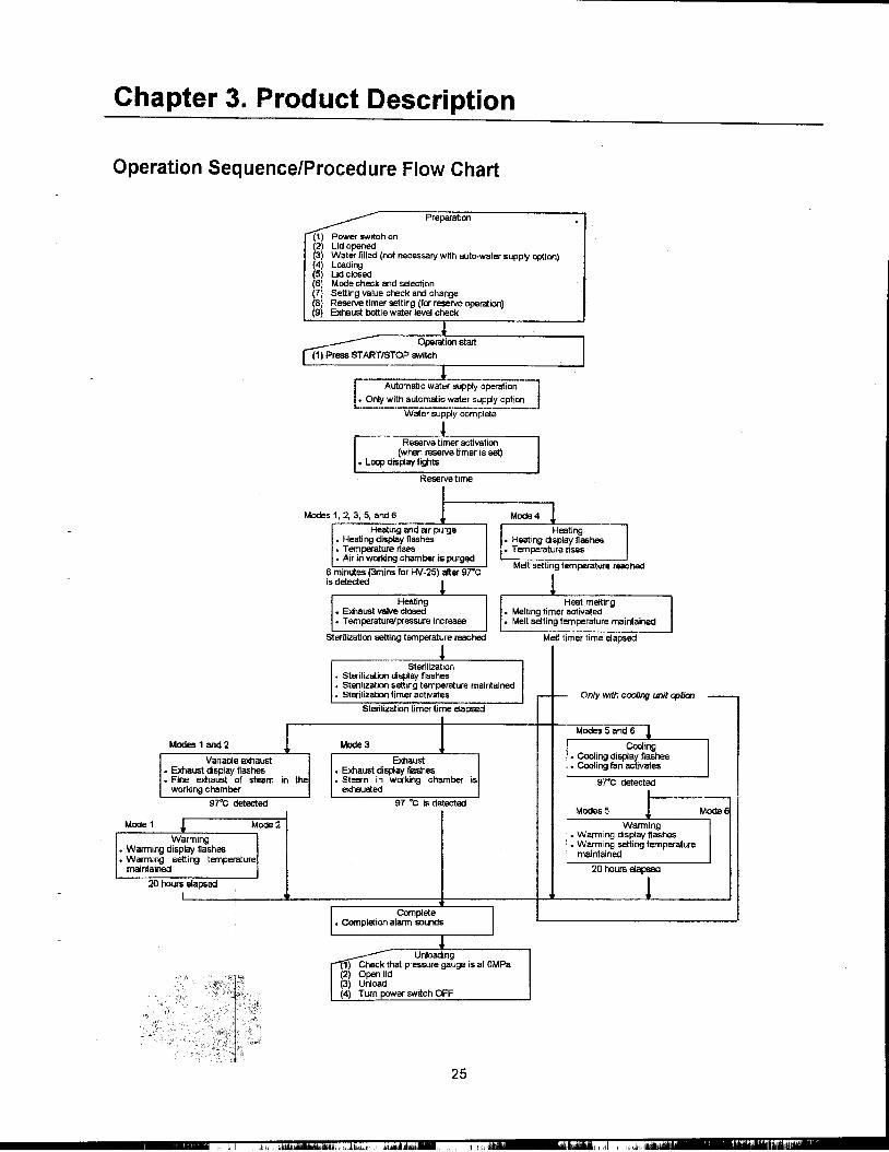
Chapter 3. Product Description
Operation Sequence/Procedure Flow Chart
Preparation
(1) Power switch on(2) Lid opened(3) Water filled (not necessary with auto-water suppo/ optioo)(4) Loading(5) Lid closed(6) Mode check Md selection(7) Setting value check and change(8) Reserve timer setting (for reserve operation)(9) Exhaust bottle water level check
nstalt
i Auto~ water~y-~~n'-'I. Only with automatic water supply option I
1Water suppo/ complete
Reserve timer activation(when reserve timer is set)
.Loop display lights
R
Modes 1, 2, 3, 5, and 6
Heating and ar purge.Heating display ftashes.Ternpe-ature rises.Air in wooong chamber is purged
6 minutes (3mins for HV-25) after e7"Cis detected
Heating Heat melting.EJ<haust valve clooed .Melting timer activated.Temperature/pressure i .Melt seI1ing temperature maintained
Sterilization seI1ing tempera Meit timer time elapsed
Sterilization.Sterilizatioo display ftashes.Sterilizatioo seiting temperature maintained.Sterilization timer activates Only with cooling unit ",fia!
Sterilization timer time elapsed
Modes 1 and 2 MOOe 3
Varia~e exhaust Exhaust.EJ<haust display ftashes .E><haust display flashes.Fire e><haust of steam in the .Steam in w~ng chamber is
working chamber exhausted
97"C detected 97 'c is detectedModes 5 Mode 6
Mode 1 Mode 2 WarmingWarming .Warming dis~lay flashes
.Warming disp~y flashes .W~rml~ setting temperature
.Warming seiting temperature maintained
maintained 20 hours elapsed
20 hours elapsed
Unloading) Check that pressure gauge is at OMPa
(2) Open lid(3) Unload(4) Turn power switch OFF
25
i, ,~"j." j

Error Monitoring Charts
.Mode 1 Sterilization -Variable exhaust -WarminDisplay Name Detec- Pre.para- Automatic Reserve Air Heating Steriliza- Variable Warming Complete
tlon tlon water sup- purge tion exhaustI
E r 1 Lack-ot-water alarm EGO
E r 2 Control temperature sensor CN2wire broken
E r 3 Over temperature (upper Internallimit temperature +3t ormore
E r 3 Over temperature (setting Internal+5OC tor 1 0 seconds
E r 3 Over temperature (setting Internal+10t tor 15 minutes
E r 4 Over cooling Internal
E r 5 Over pressure Internal
E r 6 Lid abnormal LSW1E r 7 Automatic exhaust valve LSW3
abnormalE r 8 Automatic water supply FSW
abnorma:E r 9 Heater abnormal Internal
E r L Open/close knob lock ab- LSW2 *3normal , E r F Floating sensor wire broken CN3
ErE Exhaust bottle abnormal LSW4 *3
-1 Over temperature (setting Internal+2°C or more
-2 Over cooling (setting -1 "C Internalor less)
.Mode 2 Sterilization -Variable exhaustDisplay Name Detec- Prepara- Automatic Reserve Air Heating Steriliza- Variable Complete
tion tion water sup- purge tion exhaustI
E r 1 Lack-at-water alarm EGO
E r 2 Control temperature sensor CN2wire broken
E r 3 Over temperature (upper Internallimit temperature +3t ormore
E r 3 Over temperature (setting Internal+5t tor 10 seconds
E r 3 Over temperature (setting Internal+10"C tor 15 minutes)
E r 4 Over coolin InternalE r 5 Over pre5sure Internal
E r 6 Lid ~bnormal LSW1
E r 7 Automatic exhaust valve LSW3abnormal
E r 8 Automatic water 5upply FSWabnormal
E r 9 Heater abnormal Internal
E r L Open/close knob lock ab- LSW2 *3normal E r F Floating sensor wire broken CN3
ErE Exhaust bottle abnormal LSW4 *3
*1 Over temperature (setting Internal+2"C or more
*2 Over cooling (setting -1 "C Internal
orles5)
26

.Mode 3 Sterilization -ExhaustDisplay Name Detec- Prepara- Automatic Reserve Air Heating Steriliza- Forced Complete
tion tion water sup- purge tion exhaust
piE r 1 Lack-ot-water alarm EGO
E r 2 Control temperature sensor CN2wire broken
E r 3 Over temperature (upper Internallimit temperature +3t ormore
E r 3 Over temperature (setting Internal+5t tor 10 seconds
E r 3 Over temperature (setting Internal+10t tor 15 minutes
E r 4 Over cooling Internal
E r 5 Over pressure Internal
E r 6 Lid abnormal LSW1
E r 7 Automatic exhaust valve LSW3abnormal
E r 8 Automatic water supply FSWabnormal
E r 9 Heater abnormal Internal
E r L Open/close knob lock ab- LSW2 ~ normal
E r F Floating sensor wire broken CN3
ErE Exhaust bottle abnormal LSW4~ *1 Over temperature (setting Internal
+2"":: or more*2 Over cooling (setting -1t Internal
or less
.Mode 4Display ame c- Prepara- Automatic Reserve Heating Heating Warming Complete
tion tion water sup- andIy meltin
E r 1 Lack-ot-water alarm EGO
E r 2 Control temperature sensor CN2wire broken
E r 3 Over temperature (upper Internallimit temperature +3t ormore
E r 3 Over temperature (setting Internal+5t for 10 seconds
E r 3 Over temperature (setting Internal+10t for 15 minutes
E r 4 Over coolin InternalE r 5 Over pressure Internal
E r 6 Lid abnormal LSW1
E r 7 Automatic exhaust valve LSW3abnormal
E r B Automatic water supply FSWabnormal
E r 9 Heater ab~ormal Internal
E r L Open/close knob lock ab- LSW2 ~ normal
E r F Floating sensor wire broken CN3
ErE Exhaust bottle abnormal LSW4 *3
*1 Over temperature (setting Internal+2t or more
*2 Over cooling (setting -1 t Internalor less)
27
.."",c,",~c, ~.

.Mode 5 Sterilization -Forced coolinDisplay Name Detec- Pre.para- u oma IC eserve Air Heating Steriliza- Forced Warming Complete
tion tlon water sup- purge tian coolingI
E r 1 Lack-at-water alarm EGO
E r 2 Control temperature sensor CN2wire broken
E r 3 Over temperature (upper Internallimit temperature +3"(; ormore
E r 3 Over temperature (setting Internal+5"(; for 10 seconds
E r 3 Over temperature (setting Internal+10"(; for 15 minutes)
E r 4 Over cooling Internal
E r 5 Over pressure Internal
E r 6 Lid abnormal LSW1E r 7 Automatic exhaust valve LSW3
abnormalE r8 Automatic water supply FSW
abnormalE r9 Heater abnormal Internal
E r L Open/close knob lock ab- LSW2 *3normal E r F Floating sensor wire broken CN3
ErE Exhaust bottle abnormal LSW4 *3
*1 Over temperature (setting Internal+2"(; or more)
*2 Over cooling (setting -1"(; Internalor less
.Mode 6 Sterilization -Forced coolinDisplay Name Detec- Prepara- Automatic Reserve Air Heating Steriliza- Forced Complete
tion tion water sup- purge tion coolingI
E r 1 Lack-of-water alarm EGO
E r 2 Control temperature sensor CN2wire broken
E r 3 Over temperature (upper Internallimit temperature +3"(; ormore
E r 3 Ovijr temperature (setting Internal+5"(; for 10 seconds
E r 3 Over temperature (setting Internal+10t for 15 minutes
E r 4 Over cooling Internal
E r 5 Over pressure Internal
E r 6 Lid abnormal LSW1E r 7 Automatic exhaust valve LSW3
abnormalE r 8 Automatic water supply FSW
abnormalE r 9 Heater abnormal Internal
E r L Open/close knob lock ab- LSW2 :-? normal
E r F Floatin sensor wire broken CN3ErE Exhaust bottle abnormal LSW4 *3
*1 Over temperature (setting Internal+2"(; or more
*2 Over cooling (setting -1"C Internalor less
(Refer to the following page for *1, *2 and *3)
28
"'W ,"'co""," C .,
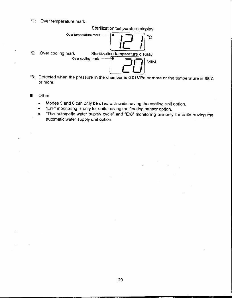
*1: Over temperature mark
Sterilization temperature display
Over temperature mark -L~~12~] °c
*2: Over cooling mark Sterilization temperature displayOver cooling mark --r=2/JJ MI N.
*3: Detected when the pressure in the chamber is 0.01 MPa or more or the temperature is 98°Cor more.
.Other
.Modes 5 and 6 can only be used with units having the cooling unit option.
."ErF'J monitoring is only for units having the floating sensor option.."The automatic water supply cycle" and "Er8" monitoring are only for units having the
automatic water supply unit option.
29
, ", "',
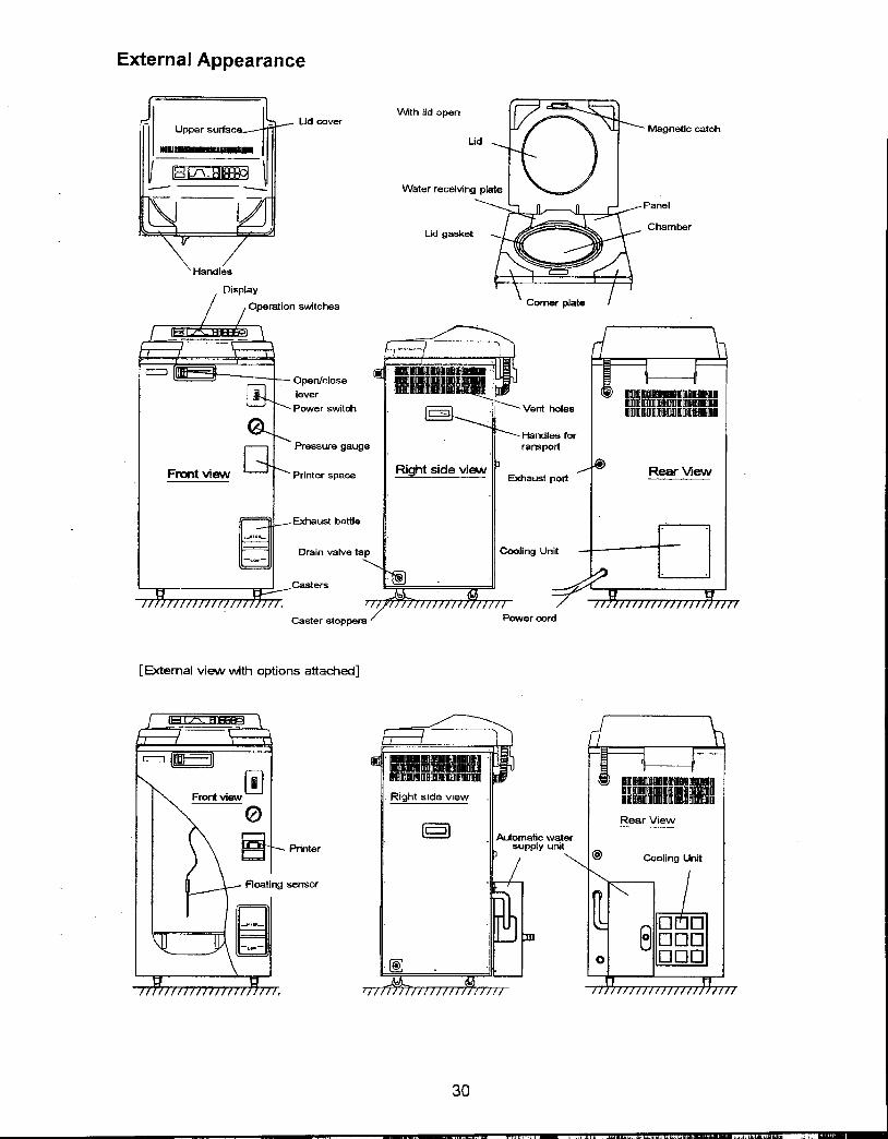
External Appearance
With lid openUd (XJver
Magnetic catch
Water receivin
anel
ChamberUd gasket
switches
Open/closeleverPower switch Vent holes
Handles forPressure gauge ransport
Fra"lt view Printer Space Right side view Rear ViewExhaust port
Exhaust bottle
Drain valve tap Cooling Unit
Casters
Caster stoppers er cord
[External view with options attadled]
,Right side view
§ Rear View~ Icwat
Printer Iy uni
sensor
30
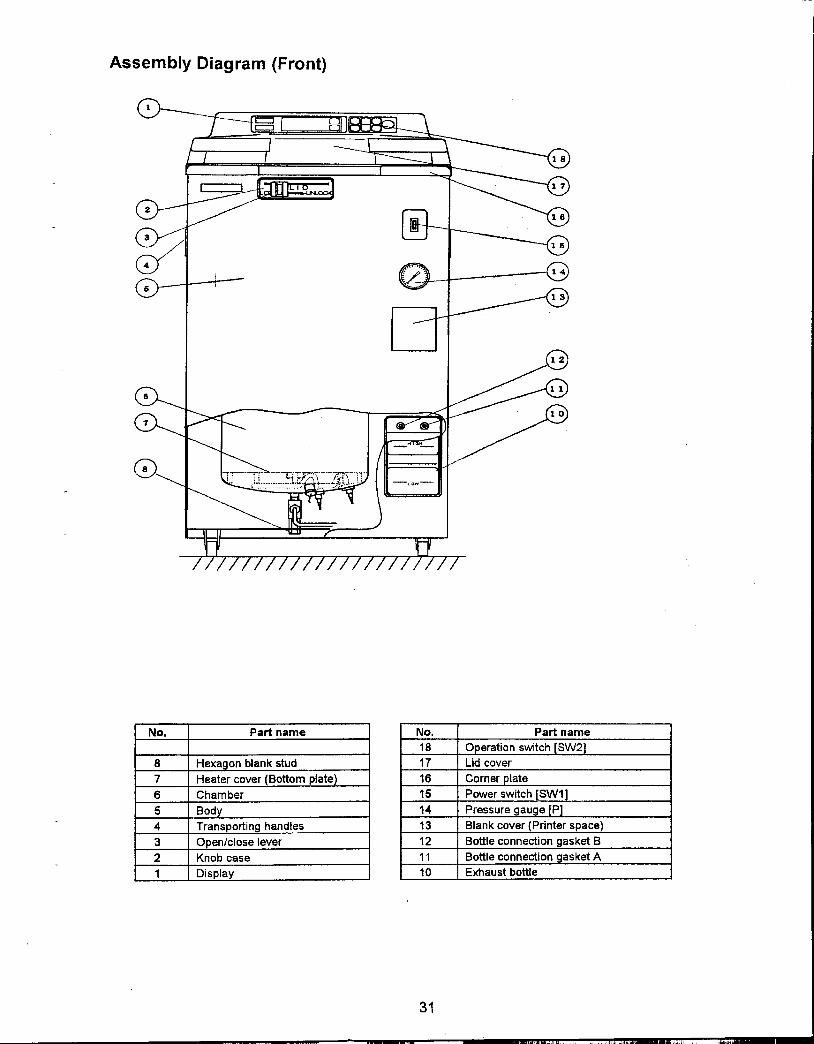
Assembly Diagram (Front)
No. Part name No. Part name18 0 eration switch SW2
8 Hexagon blank stud 17 Lid cov
7 Heater cover (Bottom plate 16 Corner
6 Chamber 15 Power
5 Body 14 Pressu
4 Transporting handles 13 Blank c
3 0 en/close lever 12 Bottle connection gasket B
2 Knob case 11 Bottle connection gasket A
1 Display 10 Exhaust bottle
31
" '" "'" .0..'
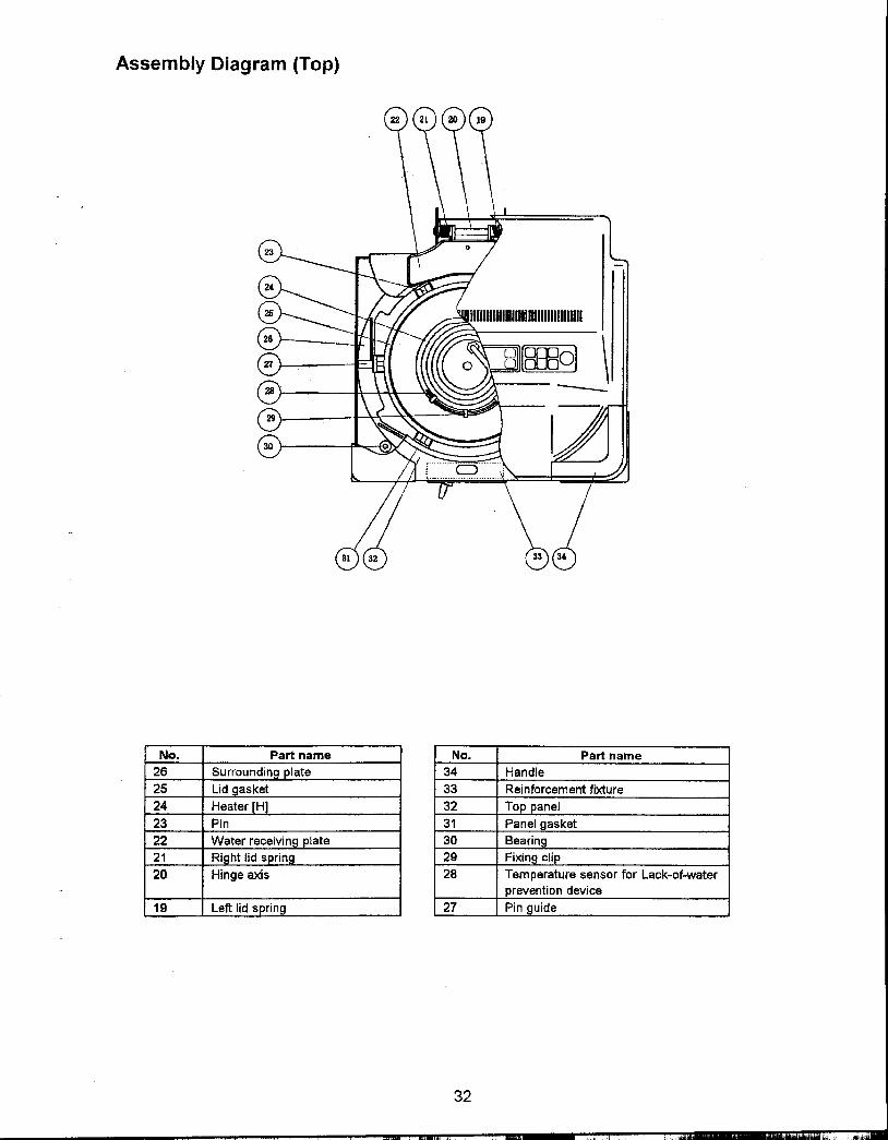
Assembly Diagram (Top)
No. Part name No. Part name26 Surroundin plate 34 Handle
25 Lid gasket 33 Reinforcement fixture
24 Heater [H] 32 Top anel
23 Pin 31 Panel gasket22 ..plate 30 Bearing21 Ri 29 Fixing clip20 Hinge axis 28 Temperature sensor for Lack-of-water
prevention device
19 Left lid s ring 27 Pin uide
32
",,'
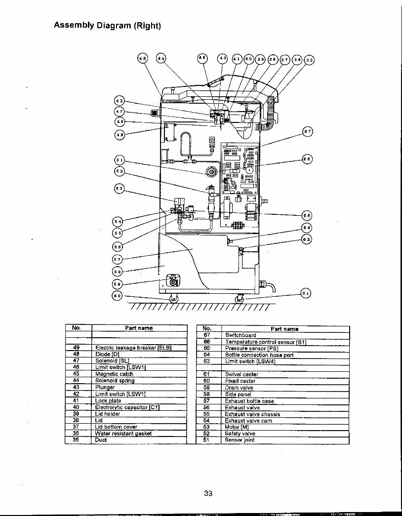
Assembly Diagram (Right)
"
No. Part name No. Part name67 Switchboard66 Tem
49 EI 65 Pres48 Di 64 Botti47 So 63 Limi46 Li45 M 61 Swivel caster44 So 60 Fixed caster43 PI 59 Drain valve42 Li 58 Side anel41 Lo 57 Exhaust bottle case40 EI 56 Exhaust valve39 Lid 55 Exhaust valve chassis38 Lid 54 Exhaust valve cam37 Lid bottom cover 53 Motor M36 Water resistant asket 52 Safet valve35 Duct 51 Sensor joint
33
"""'".. "'" Iii ".,

Assembly Diagram (Back)
IIIIm Im~ I 001100 lID lID 1m m~ ~OO ~~I M~ ~
OO~~~~rnEIIDIID~llI:IJl!llJlIDlIDmiIIOO~OO[ll]
I~OO~OOIlD 1m ~II ~IIIID II ~OO~1I11 mn
.
'-
..
No. Part name73 Power cord
72 Cable gland
71 Grommet with membrane
70 Blank late (Fan s ace)
69 Grommet (for exhaust)
68 Grommet
34
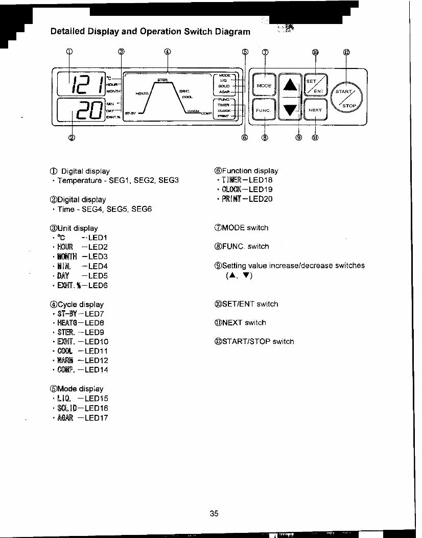
Detailed Display and Operation Switch Diagram c"",-
.4 @
1 .:1 I $TER .SET /c::: I HeATG!\~ MODE hNT
i:! 0 E)QoiT% sr-BY J L FUNC ~ NEXT
6 9
<D Digital display @Function display.Temperature -SEG1, SEG2, SEG3 .1r~ilElR-LED18
.CIL~-LED19
@Digital display .~~Nl1f -LED20
.Time -SEG4, SEGS, SEG6
@Unit display CVMODE switch
.OC -LED1
.~(Q!)JJR -LED2 @FUNC. switch
.Dl1f~ -LED3
.I~~. -LED4 @Setting value increase/decrease switches
.DAY -LEDS ("", "')
.EXIHI1o %-LED6
@Cycle display @)SET/ENT switch
.S1-18Y-LED7
.~1rG-LED8 @NEXT switch
.S1f!ERo -LED9
.~lo -LED10 @START/STOP switch
.COOl -LED11
.IR -LED12.CJJrfJ!o -LED14
(§)Mode dispiay.l~Q. -LED15.SOl~ID-LED16
.liI.GM -LED17
35
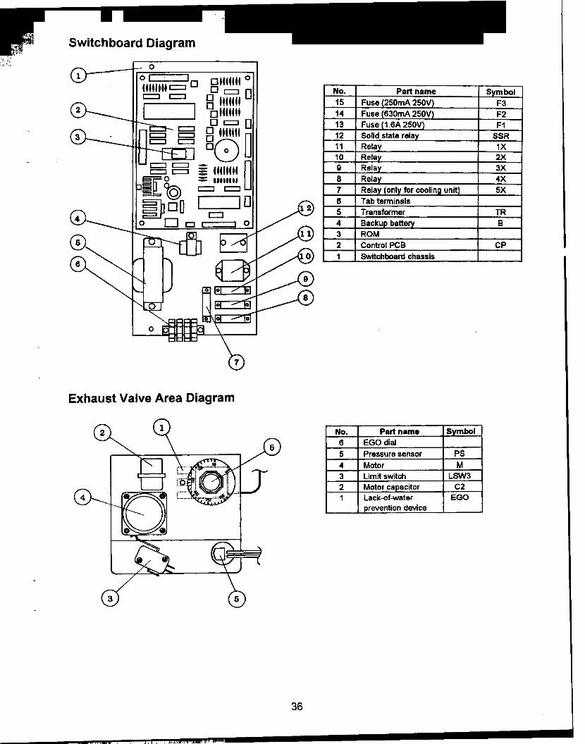
Switchboard Diagram
ottttttl 0
0 c=:I 0 No. S mbol
I I 8 Ilfffll 15 Fus F3, I ollffffl 14 Fus F2
c:::J 0 L=:J 0 13 Fus F1B B Itffttl n 12 Soli SSR
Or-;;"'\ U 11 Rela 1X~ 10 Relay 2X
B B § t4111ttt n 9 Relay 3X0 = IIIIIIII U 8 Relay 4X
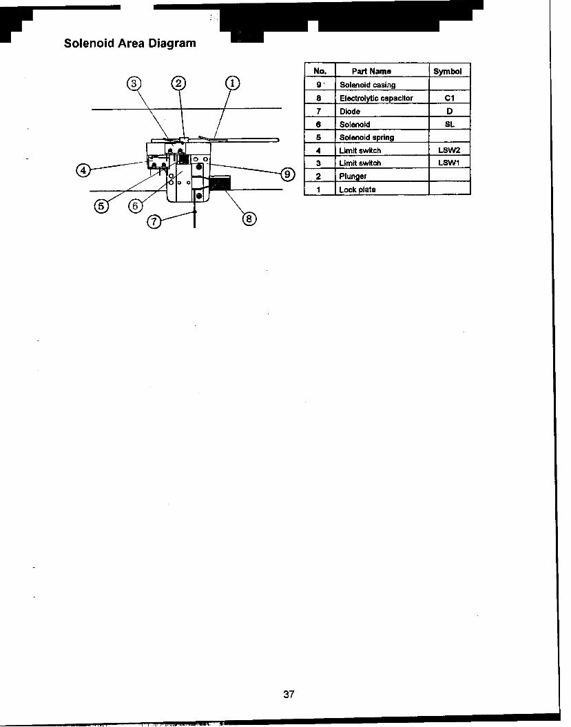
Solenoid Area Diagram
No. Part Name Symbol9 ' Solenoid casing
8 Electrolytic capacitor C1
7 Diode D
6 Solenoid SL
5 Solenoid spring
4 Limit switch LSW2
3 Limit switch LSW1
2 Plunger
1 Lock plate
37

Optional Accessories Diagrams
.Printer
, No. Part name S mbol#' 4 Switching power SR
3 Printer P2 Printer case1 Printer holder
.Automatic water supply unit
No. Part name Symbol8 Unit casin
7 Pi in holder
6 Solenoid valve SV1
5 Flexible tube (short)4 Float switch (water FSW
level detector3 Flexible tube (long)
2 Unit fittin plate1 Rela ex
.Cooling unit
No. Part name bol
5 Fan casin
4 Filter3 Fan fittin late2 Filter holder
1 Fan FAN
38
.." ]1

Piping Diagram
1Chamber
E>d1aust bottle
~ Wth automatic water supply ' 1I ..,i :.I
i (water supply) !! ii Check valve iI ,
i ~ 'J\.eteri pipingi i! !i ii !i i
j !! ii !i i! i! ii !! i! !i !: ;I .L ~ 39
" ~,

Wiring Diagram
ELB-r---, , , , ,&. ! IC ' .
-! I ii .:1 ! ' ~ :
i : ., Ii ', I 1
-, ,-: ,I '
2, ,i ', ,i :, Ii '-1i ', 1i ', ,i ', Ii '
: I I ':! I ,!!, I I"I , ,'I, .'I
i ! !i I: ' I"I I ,i i: i I':,I , 1 I: i i:'! ' ,I!
i ji ii 5X ', I, ,I I
! !i ii ii ii ,i ! I 1110 g 8 7 e 5 -4 3
i i i CN7i ii- i! i'-Autodave -,"th pinteF-' ,-_Autoclave ,,"Ih -., ,-Autoclave IMth ,automatic water cooling fan
II.supplIer
CP
! ! CN4 CN1
10 9 8 7 6 5 4 3
I
! BI
I
I ii ' ; , ~ --AlAodave -,"th floating sensor 26
SW ~()
DP
DP Display printed circuit board S1 Ten-1:Jerature sensor for controlCP Control printed circuit board S2 Floating sensorSW Operation switch PS Pressure sensorELB Circuit Brecker EGO Lac~o1-water operation prevention deviceC3 Film capacitor LSW1 Limit switch (lever open/cloce)TR Transformer LSW2 LirrYt switch (lever lock)F Fuse LS\N3 LirrYt switch (exhaust valve full close)M Motor LSW4 LirrYt switch (bottle housing)C2 Capacitor for motor FSW Water level sensor
SL Solenoid SSR Solid state relayD Diode 1X Relay(heater)C1 Electrolytic capacitor 2X Relay(exhaust valve closing)SV1 Solenoid valve(controls water suppiy) 3X Relay(exhaust valve opening)
FAN Fan 4X Relay(solenoid)H Heater 5X Relay(fan)B Backup battery 6X Relay(for water supply solenoid valve)V1 Varistor P PrinterV2 Varistor SR Switching power supply
40
.,", .L'"co.'

Connector Table
.Control PCB
Connector Terminal Terminal Connected part Connected part functionNo. No. function
Display PCB CN1 1 -26 LED output DP display PCB LED lightinginput andoutput Operation Operation switch opera-
switch in ut tions1 High temp.
sideThermistorin ut
Temperature CN2 2 Low temp. S1 Temperature Temperature detection ininput side control sensor the chamber
Thermistorin ut
3 Common
1 High temp.sideThermistorin ut
Temperature CN3 2 Low temp. S2 Floating sensor Temperature detectioninput (option) side for substance being ster-
Thermistor ilizedin ut
3 Common
1 +12V None2 Input EGO lack-of-water Lack-of-water detection
revention device3 +12V LSW1 Limit switch Lever open/close detec-
tion4 In
External input CN 4 5 + LSW2 Limit switch Lever lock detection6 In7 + LSW3 Limit switch Exhaust valve full close
detection8 In ut9 +12V LSW4 Limit switch Exhaust bottle correct
position detection10 In ut1 +12V 6X Relay SV1 Solenoid valve (wa-
ter su I) activation2 Out3 +12
4 Out5 +12
NoneExternal input CN5 6 Ou
and output (option) 7 +1
8 au9 +1 FWS Water level Water level (in the
detector chamber detection10 In ut11 + V None
12 In ut
41
~ ., ",'""'

Connector Terminal Terminal Connected part Connected part functionNo. No. function
1 +12V NonePressure in- 2 +5V
putCN6 3 GND PS Pressure (in the cham-
ber)4 Pressure Pressure sensor detection
data in ut
1 +5V SSR H Heater controlSolid state rela
2 +12V None3 Output (-) SSR Same as terminal No.1
Solid state rela4 +12V 1X relay H Heater control5 Out ut -6 +12V 2X relay M
External out- CN 7 7 Output (-) Motor operation (exhaustput valve closing)
8 +12V 3X Relay M9 Output (-) Motor operation (exhaust
valve 0 enin10 +1 4X Relay SL11 Out Solenoid 0 eration12 +12 5X Relay (option) FAN13 Out Fan 0 eration
Backup 1 OV mpu B Data-backup batterybattery input CN 8 Backup battery
2 +3V in ut
1 AC14V in ut TR PCB powerPower input CN 9 2 AC14V in ut Transformer
3 GNDPrinter power CN10 1 +5V input SR Printer power source
input (option) Switching power2 OV in ut
Printer input CN11 1 -34 Print data P Data printingand output (option) input and Printer
out ut
.Display PCB
Connector Terminal Terminal Connected part Connected part functionNo. No. function
Control PCB CN 1 1 -26 LED output LED controlinput and CP C t I PCBoutput Operation on ro Detection of operation
switch in ut switch 0 erationsOperation CN 2 1 -8 Operation SW Operation switch opera-switch in ut switch in ut 0 eration switch tions
42
."'
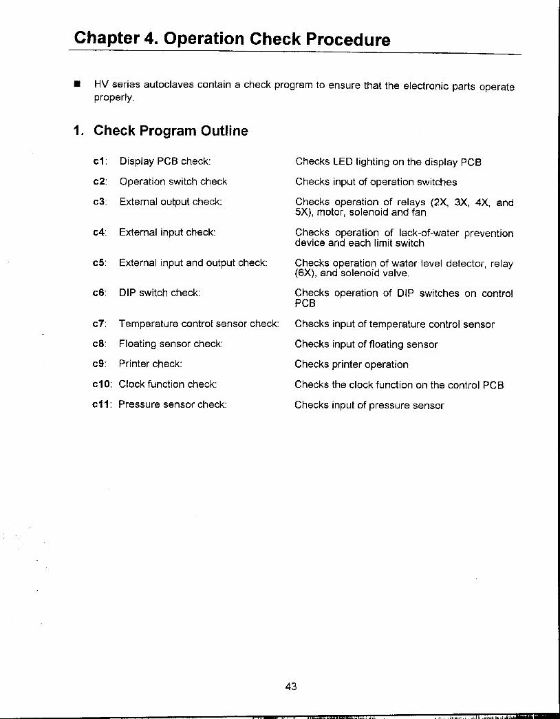
Chapter 4. Operation Check Procedure
.HV series autoclaves contain a check program to ensure that the electronic parts operate
properly.
1. Check Program Outline
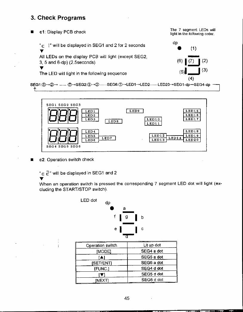
c1: Display PCB check: Checks LED lighting on the display PCB
c2: Operation switch check Checks input of operation switches
c3: External output check: Checks operation of relays (2X, 3X, 4X, and5X), motor, solenoid and fan
c4: External input check: Checks operation of lack-of-water preventiondevice and each I imit switch
cS: External input and output check: Checks operation of water level detector, relay(6X), and solenoid valve.
c6: DIP switch check: Checks operation of DIP switches on controlPCB
c1: Temperature control sensor check: Checks input of temperature control sensor
c8: Floating sensor check: Checks input of floating sensor
c9: Printer check: Checks printer operation
c10: Clock function check: Checks the clock function on the control PCB
c11: Pressure sensor check: Checks input of pressure sensor
43
c~.,,'" " II"""",""""""

2. Check Program Startup
CD Turn the power switch off.=w
~ Remove the right side panel.
@ Turn on No.4 of DIP switch S2 on thecontrol PCB.
@ Turn the power switch on.
@ Check program c1 will startup.
~
.During the check program, the items of checkprogram are changed over as shown below by pressingthe START/STOP switch,
c1 --c2 --c3 c11 --c1 ...
.When the operation check is completed, turn the power switch off and return No.4 of DIPswitch S2 to OFF.
CDPower switch
Fixing screws
@Right side panel
OFF sideON side
@No. 4 of DIP switch 52
~OFF side ~
.V No.4 S2ON side
~
44
"",..jllt"...""",,
3. Check Programs
..The 7 segment LEDs will.c1. Display PCB check light in the following order.
"c I" will be displayed in SEG1 and 2 for 2 seconds dP. (1)'f'All LEOs on the display PCB will light (except SEG2, -3,5 and 6-dp) (2.5seconds) (6) I ~ (2)
;he LED will light in the following sequence (sJ.-J (3)
(4)SEG1:Q)-@- (7)-SEG2:Q)-@ SEG6:<:7)-LED1-LED2 LED20---SEG1-dp-SEG4-dp
SEal SEG2 SEG3~8BB~EDI I LED9 I LED15
LED2 LED16LED3 I T=~O I ~ED1O LED11
I LED8 ILEDll
rawe'Ba LED4 LED18
LED5 LED12 LED19
LED6 LED7 LED13 LED14 LED20
SEG4 SEG5 SEG6
.c2: Operation switch check
"c 2" will be displayed in SEG1 and 2'f'When an operation switch is pressed the corresponding 7 segment LED dot will light (ex-cluding the START/STOP switch).
LED dot dp
.a -fig I b-e I I c
-r-Operation switch Lit up dot
[MODE SEG4 a dot
[.A.] SEG5 a dot
[SET/ENT] SEG6 a dot
[FUNC.] SEG4 d dot
["'] SEG5 d dot[NEXT] SEG6 d dot
45
" "".ill" ,,'I

.c3: External output check
"c :3" will be displayed in SEG1 and 2TThe part corresponding to the operation switch will operate (excluding SSR and 1X).
a itch Movin art-1 art-22X rela alve c3X rela alve 04X rela5X rela
Only tor cooling unit option
.c4: External input check
.0 c L{" will be displayed in SEG1 and 2
TThe dots of the 7 segment LED will light according to the external input.
Lit u dotLack-ot-water SEG4 a dotLimit switch L SEG5 a dotLimit switch L SEG6 a dotLimit switch L SEG4 d dotLimit switch L on) SEG5 d dot
.Setting values for lack-of-water prevention device
HV-25 HV-50 HV-85 HV-110160°C 170°C 160°C 160°C
.c5: External input and output check (only for automatic water supply unit option)
"c 5" will be displayed in SEG1 and 2TThe part will move depending on the operation switch.The dots of the 7 segment LED will light according to each external input.
Activated Activated art-26X rei Solenoid valve (water su
utFSW Water level detector etection in the chambe
46
'" ..,,", ""'".- ""
---
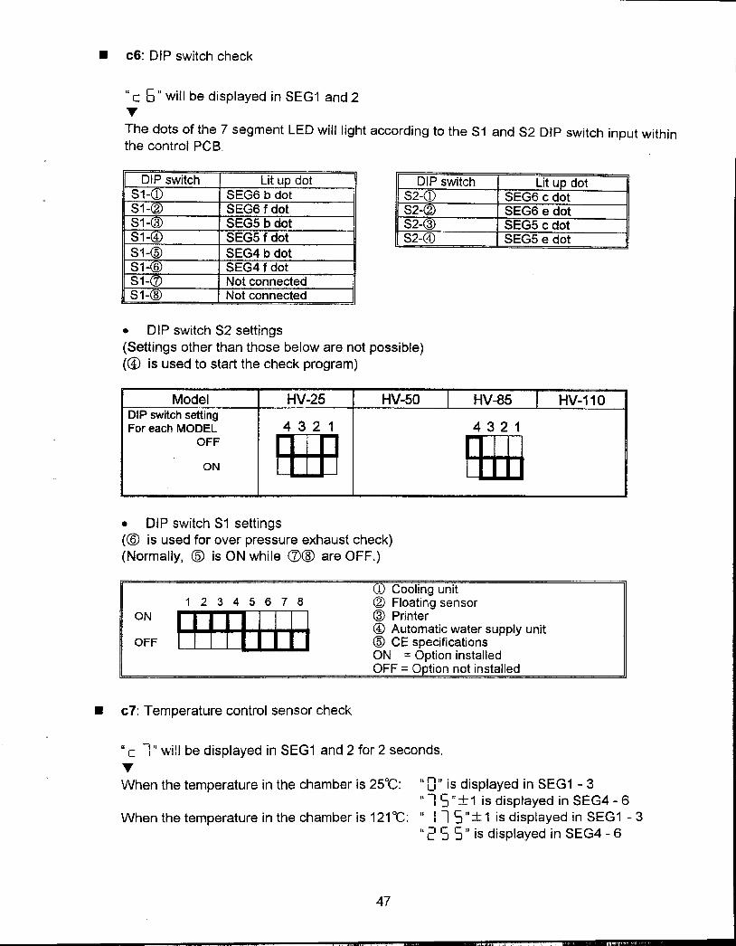
.c6: DIP switch check
"c 5" will be displayed in SEG1 and 2TThe dots of the 7 segment LED will light according to the 81 and 82 DIP switch input withinthe control PCB.
D switch Lit u dot DIP switch Lit u dot81 8EG6 b dot 52-a) 5EG6 c dot81 8EG6 f dot 82- SEG6 e dot81 SEG5 b dot 82- 3 8EG5 c dot81 SEG5 f dot 82-@ SEG5 e dot81-@ 8EG4 b dot81- 6 SEG4 f dot81- Not connectedS 1- 8 Not connected
.DIP switch S2 settings(Settings other than those below are not possible)(@ is used to start the check program)
Model HV-25 HV-50 HV-85 HV-110DIP switch settingFor each MODEL 4 3 2 1 4 3 2 1
0;: B:m fHB
.DIP switch S1 settings(@ is used for over pressure exhaust check)(Normally, ($) is ON while (1)@ are OFF.)
1 Cooling unit1 2 3 4 5 6 7 8 (2) Floating sensor
ON mr J:I:D @ Printer@ Automatic water supply unit
OFF (Q) CE specificationsON = Option installedOFF = 0 tion not installed
.c1: Temperature control sensor check
"c 1" wi!1 be displayed in SEG1 and 2 for 2 seconds.
TWhen the temperature in the chamber is 25°C: "0" is displayed in SEG1 -3
"1 S":t1 is displayed in SEG4 -6When the temperature in the chamber is 121°C: " 11 S":!: 1 is displayed in SEG1 -3
"2 5 5" is displayed in SEG4 -6
47
;0

.c8: Floating sensor check
"c 8" will be displayed in SEG1 and 2 for 2 seconds.TWhen the temperature in the chamber is 25°C: "0" is displayed in SEG1 -3
"1 5"::t: 1 is displayed in SEG4 -6When the temperature in the chamber is 121°C:" 11 5.'::t: 1 is displayed in SEG1 -3
"255" is displayed in SEG4 -6
.c9: Printer check
"c g" will be displayed in SEG1 and 2TThe following data will be printed out when an operation switch is pressed (excluding theSTART/STOP switch).
Print output data
*HIRAYAMA MFG CORP*
Date:
Time:
Name:
Cycle Count: 0001*** Setting ***
Mode: 1 LiquidSter. Temp: 121. CSter. Time: 20min.Warm Temp: 500 CExhaust %: 10%
-* Cycle Start ***
ITimelT empl Press! Stat I
48
"".., "'
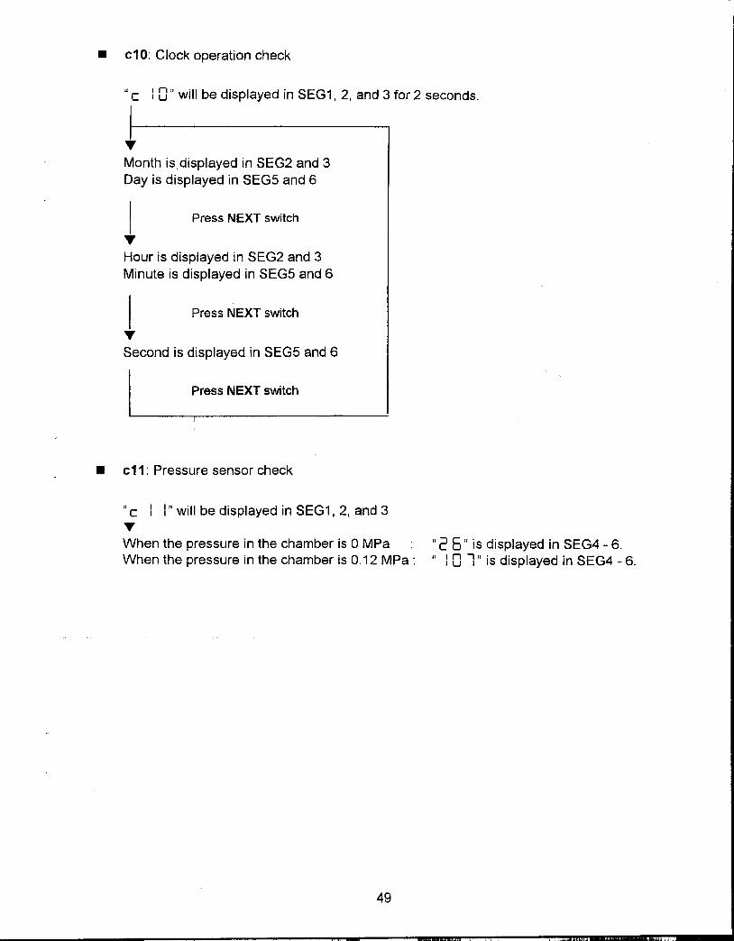
.c10: Clock operation check
"c I 0" will be displayed in SEG1, 2, and 3 for 2 seconds.
Month is displayed in SEG2 and 3Day is displayed in SEG5 and 6
I Press NEXT switch
Hour is displayed in SEG2 and 3Minute is displayed in SEG5 and 6
I Press NEXT switch
Second is displayed in SEG5 and 6
I :ress NEXT switch I
.c11: Pressure sensor check
"c I I'J will be displayed in SEG1, 2J and 3
When the pressure in the chamber is 0 MPa ".:: 5 JI is displayed in SEG4 -6.
When the pressure in the chamber is 0.12 MPa: "I 0 1" is displayed in SEG4 -6.
49
h"
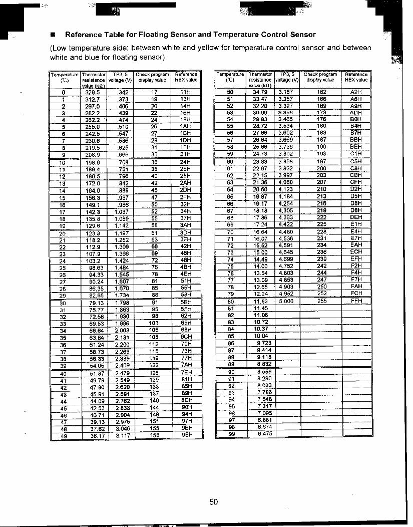
.Reference Table for Floating Sensor and Temperature Control Sensor
(Low temperature side: between white and yellow for temperature control sensor and between
white and blue for floating sensor)
Tem~rature Thermistor TP3, 5 Ch.eck program Reference Tem~erature Thermistor TP3, 5 Check program Reference(C) resistance voltage (V) display value HEX value (C) resistance voltage (V) display value HEX value
value kQ value kg
0 329.5 .342 17 11H 50 34.79 3.187 162 A2H1 312.7 .373 19 13H 51 33.47 3.257 166 A6H2 297.0 .406 20 14H 52 32.20 3.327 169 A9H3 282.2 .439 22 16H 53 30.99 3.396 173 ADH4 262.2 .474 24 18H 54 29.83 3.465 176 BOH5 255.0 .510 26 1AH 55 28.72 3.534 180 B4H6 242.5 .547 27 18H 56 27.66 3.602 183 87H7 230.6 .586 29 1DH 57 26.64 3.669 187 88H8 219.5 .625 31 1FH 58 25.66 3.736 190 BEH9 208.9 .666 33 21H 59 2473 3.802 193 C1H
10 198.9 .708 36 24H 60 2383 3.868 197 C5H11 189.4 .751 38 26H 61 22.97 3.932 200 C8H12 180.5 .796 40 28H 62 22.15 3.997 203 CBH13 172.0 .842 42 2AH 63 21.36 4.060 207 CFH14 164.0 .889 45 2DH 64 20.60 4.123 210 D2H15 156.3 .937 47 2FH 65 19.87 4.184 213 D5H16 149.1 .986 50 32H 66 19.17 4.254 216 D8H17 142.3 1.037 52 34H 67 18.18 4.305 219 D8H18 135.8 1.089 55 37H 68 1786 4.363 222 DEH19 129.6 1.142 58 3AH 69 1724 4.422 225 E1H20 123.8 1.197 61 3DH 70 1664 4.480 228 E4H21 118.2 1.252 63 3FH 71 16.07 4.536 231 E7H22 112.9 1.309 66 42H 72 15.52 4.591 234 EAH23 107.9 1.366 69 45H 73 15.00 4.645 236 ECH24 103.2 1.424 72 48H 74 14.49 4.699 239 EFH25 98.63 1.484 75 48H 75 14.00 4.752 242 F2H26 94.33 1.545 78 4EH 76 13.54 4.803 244 F4H27 90.24 1.607 81 51H 77 13.09 4.853 247 F7H28 86.35 1.670 85 55H 78 1265 4.903 250 FAH29 82.65 1.734 88 58H 79 1224 4_952 252 FCH30 79.13 1.798 91 5BH 80 1183 5000 255 FFH31 75.77 1.863 95 5FH 81 114532 72.58 1.930 98 62H 82 11.0833 69.53 1.996 101 65H 83 10.7234 66.64 2.063 105 68H 84 10.3735 63.84 2.131 108 6CH 85 10.0436 61.24 2.200 112 70H 86 9.72337 58.73 2.269 115 73H 87 9.41438 56.33 2.339 119 77H 88 9.11839 54.05 2.409 122 7AH 89 8.832
40 51 87 2.479 126 7EH 90 8.55641 49.79 2.549 129 81H 91 8.29042 47.80 2.620 133 85H 92 8.03343 45.91 2.691 137 89H 93 7.78644 44.09 2.762 140 8CH 94 7.54845 42.53 2.833 144 90H 95 7.31746 40.71 2.904 148 94H 96 7.09547 39.13 2.975 151 97H 97 6.88148 37.62 3.046 155 9BH 98 667449 36.17 3.117 158 9EH 99 6475
50
~.". i "",,ll. '"
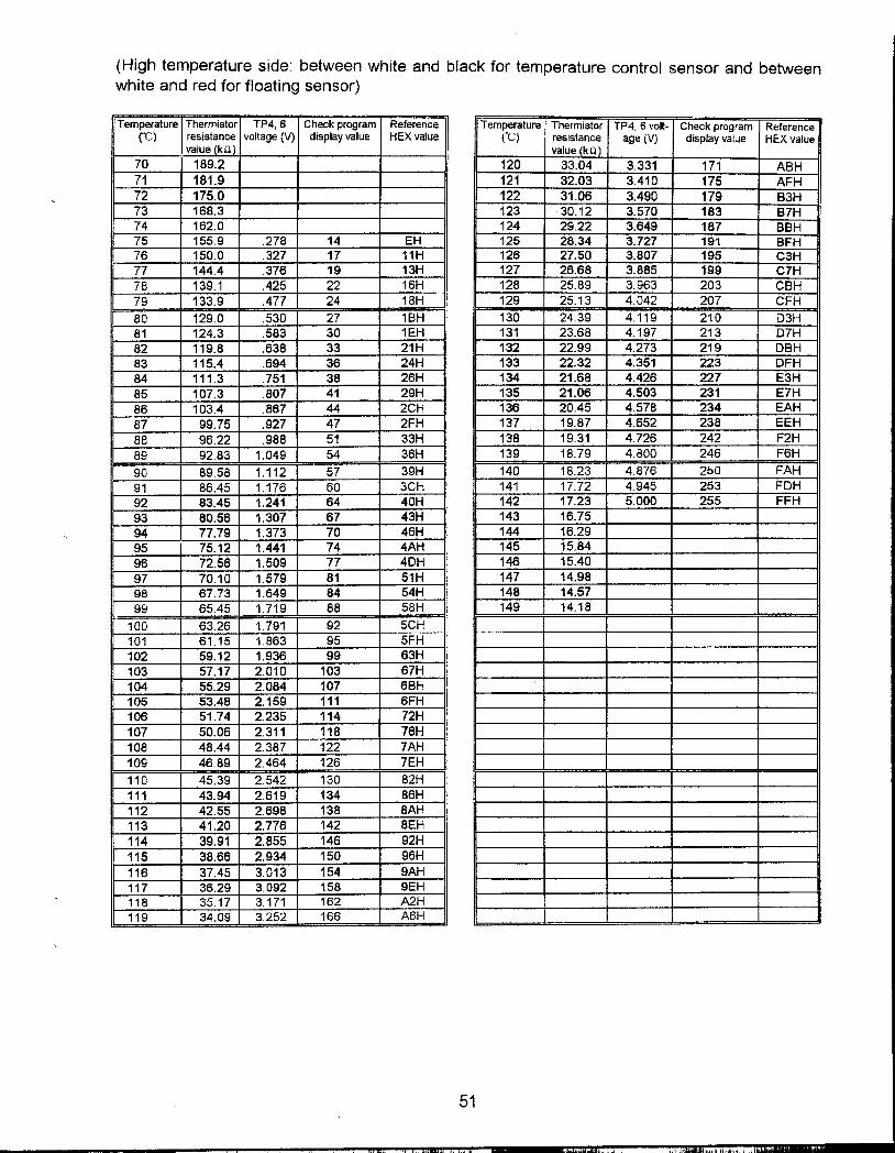
(High temperature side: between white and black for temperature control sensor and betweenwhite and red for floating sensor)
Temperature Thermistor TP4, 6 Check program Reference Temperature Thermistor TP4, 6 volt- Check program Reference("C) resistance voltage (V) display value HEX value (~) resistance age (V) display vaiue HEX value
value ko value kO
70 189.2 120 33.04 3.331 171 ABH71 181.9 121 32.03 3.410 175 AFH72 175.0 122 31.06 3.490 179 83H73 168.3 123 30.12 3.570 183 87H74 162.0 124 29.22 3.649 187 BBH75 155.9 .278 14 EH 125 28.34 3.727 191 BFH76 150.0 .327 17 11H 126 27.50 3.807 195 C3H77 144.4 .376 19 13H 127 26.68 3.885 199 C7H78 139.1 .425 22 16H 128 25.89 3.963 203 CBH79 133.9 .477 24 18H 129 25.13 4.042 207 CFH
80 129.0 .530 27 1BH 130 24.39 4.119 210 D3H81 124.3 .583 30 1EH 131 23.68 4.197 213 D7H82 119.8 .638 33 21 H 132 22.99 4.273 219 DBH83 115.4 .694 36 24H 133 22.32 4.351 223 DFH84 111.3 .751 38 26H 134 21.68 4.426 227 E3H85 107.3 .807 41 29H 135 21.06 4.503 231 E7H86 103.4 .867 44 2CH 136 20.45 4.578 234 EAH87 99.75 .927 47 2FH 137 19.87 4.652 238 EEH88 96.22 .988 51 33H 138 19.31 4.726 242 F2H89 92.83 1.049 54 36H 139 18.79 4.800 246 F6H
90 89.58 1.112 57 39H 140 18.23 4.876 250 FAH91 86.45 1.176 60 3CH 141 17.72 4.945 253 FDH92 83.45 1.241 64 40H 142 17.23 5.000 255 FFH93 80.56 1.307 67 43H 143 16.7594 77.79 1.373 70 46H 144 16.2995 75.12 1.441 74 4AH 145 15.8496 72.56 1.509 77 4DH 146 15.4097 70.10 1.579 81 51H 147 14.9898 67.73 1.649 84 54H 148 14.5799 65.45 1.719 88 58H 149 14.18
100 63.26 1.791 92 5CH101 61.15 1.863 95 5FH102 59.12 1.936 99 63H103 57.17 2.010 103 67H104 55.29 2.084 107 68H105 53.48 2.159 111 6FH106 51.74 2.235 114 72H107 50.06 2.311 118 76H108 48.44 2.387 122 7AH109 46.89 2.464 126 7EH
110 45.39 2.542 130 82H111 43.94 2.619 134 86H112 42.55 2.698 138 8AH113 41.20 2.776 142 8EH114 39.91 2.855 146 92H115 38.66 2.934 150 96H116 37.45 3.013 154 9AH117 36.29 3.092 158 9EH118 35.17 3.171 162 A2H119 34.09 3.252 166 A6H
51
", ...,.~",,;
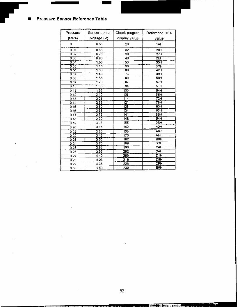
.Pressure Sensor Reference Table
Pressure Sensor output Check program Reference HEX
(Mpa) voltage (V) display value value
a 0.50 26 1AH
0.01 063 32 20H0.02 0.76 39 27H0.03 0.90 46 2EH0.04 1.03 53 35H0.05 1.16 60 3CH0.06 1.30 66 42H0.07 1.43 73 49H0.08 1.56 80 50H0.09 1.70 87 57H0.10 1 83 94 5EH
0.11 1.96 100 64H0.12 2.10 107 6BH0.13 2.23 114 72H0.14 2.36 121 79H0.15 2.50 128 80H0.16 2.63 134 86H0.17 2.76 141 8BH0.18 2.90 148 94H0.19 3.03 155 9BH020 3.16 162 A2H
0.21 3.30 168 A8H0.22 3.43 175 AFH0.23 3.56 182 B6H0.24 3.70 189 BDH0.25 3.83 196 C4H0.26 3.96 202 CAH0.27 4.10 209 D1H0.28 4.23 216 D8H0.29 436 223 DFH030 450 230 E6H
52
' ";'
1..., Iii i it ~.,