american-darling fire hydrant5 ” b-84-bkmphydrants.com/downloads/b-84-b-brochure.pdf ·...
TRANSCRIPT
AMERICAN FLOW CONTROLIt’s What We Know.®
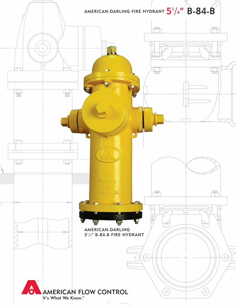
AMERICAN-DARLING51/4” B-84-B FIRE HYDRANT
51/4” B-84-BAMERICAN-DARLING FIRE HYDRANT
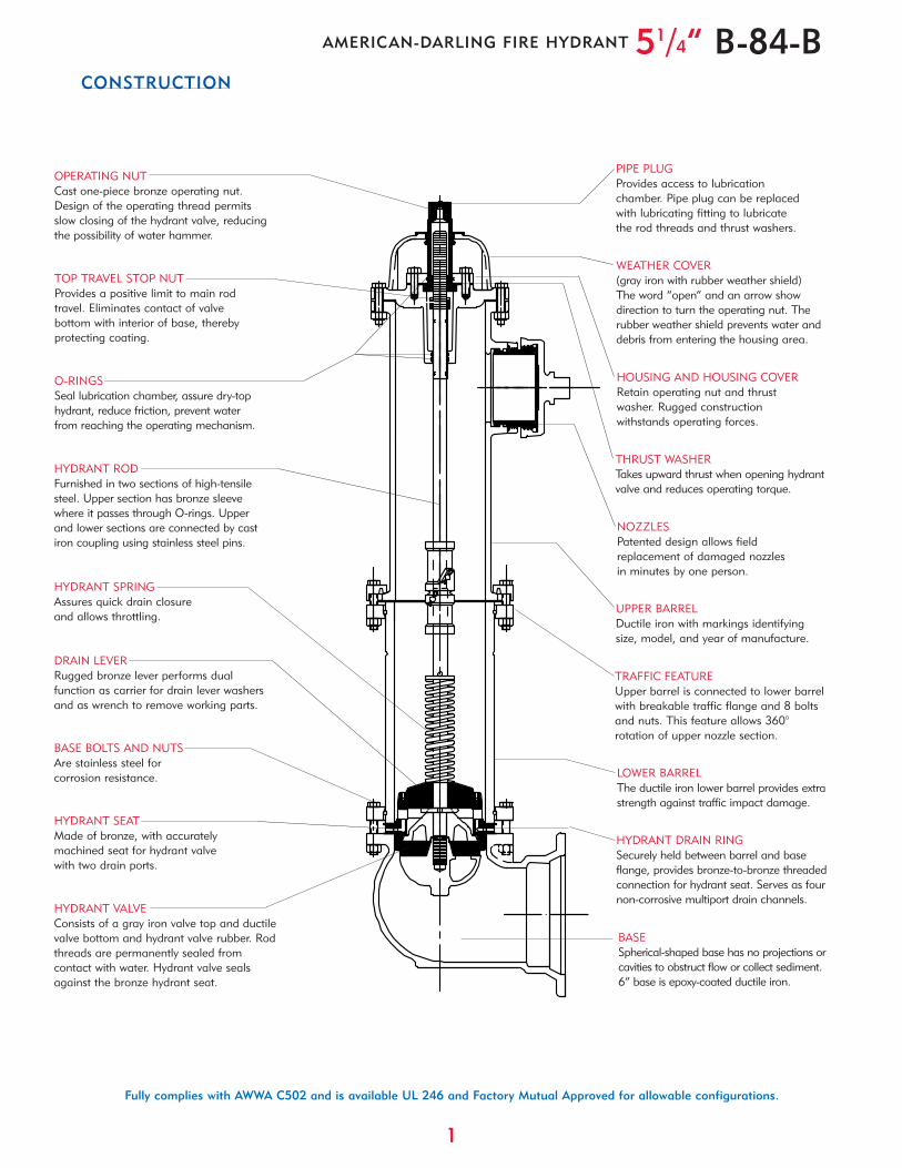
DRAIN LEVERRugged bronze lever performs dualfunction as carrier for drain lever washersand as wrench to remove working parts.
1
Fully complies with AWWA C502 and is available UL 246 and Factory Mutual Approved for allowable configurations.
CONSTRUCTION
51/4” B-84-BAMERICAN-DARLING FIRE HYDRANT
HYDRANT SPRINGAssures quick drain closureand allows throttling.
OPERATING NUTCast one-piece bronze operating nut.Design of the operating thread permitsslow closing of the hydrant valve, reducingthe possibility of water hammer.
O-RINGSSeal lubrication chamber, assure dry-tophydrant, reduce friction, prevent waterfrom reaching the operating mechanism.
HYDRANT RODFurnished in two sections of high-tensilesteel. Upper section has bronze sleevewhere it passes through O-rings. Upperand lower sections are connected by castiron coupling using stainless steel pins.
HYDRANT VALVEConsists of a gray iron valve top and ductilevalve bottom and hydrant valve rubber. Rodthreads are permanently sealed fromcontact with water. Hydrant valve sealsagainst the bronze hydrant seat.
HYDRANT SEATMade of bronze, with accuratelymachined seat for hydrant valvewith two drain ports.
HYDRANT DRAIN RINGSecurely held between barrel and baseflange, provides bronze-to-bronze threadedconnection for hydrant seat. Serves as fournon-corrosive multiport drain channels.
PIPE PLUGProvides access to lubricationchamber. Pipe plug can be replacedwith lubricating fitting to lubricatethe rod threads and thrust washers.
WEATHER COVER(gray iron with rubber weather shield)The word “open” and an arrow showdirection to turn the operating nut. Therubber weather shield prevents water anddebris from entering the housing area.
HOUSING AND HOUSING COVERRetain operating nut and thrustwasher. Rugged constructionwithstands operating forces.
THRUST WASHERTakes upward thrust when opening hydrantvalve and reduces operating torque.
LOWER BARRELThe ductile iron lower barrel provides extrastrength against traffic impact damage.
UPPER BARRELDuctile iron with markings identifyingsize, model, and year of manufacture.
NOZZLESPatented design allows fieldreplacement of damaged nozzlesin minutes by one person.
BASE BOLTS AND NUTSAre stainless steel forcorrosion resistance.
BASESpherical-shaped base has no projections orcavities to obstruct flow or collect sediment.6” base is epoxy-coated ductile iron.
TRAFFIC FEATUREUpper barrel is connected to lower barrelwith breakable traffic flange and 8 boltsand nuts. This feature allows 360°rotation of upper nozzle section.
TOP TRAVEL STOP NUTProvides a positive limit to main rodtravel. Eliminates contact of valvebottom with interior of base, therebyprotecting coating.
2
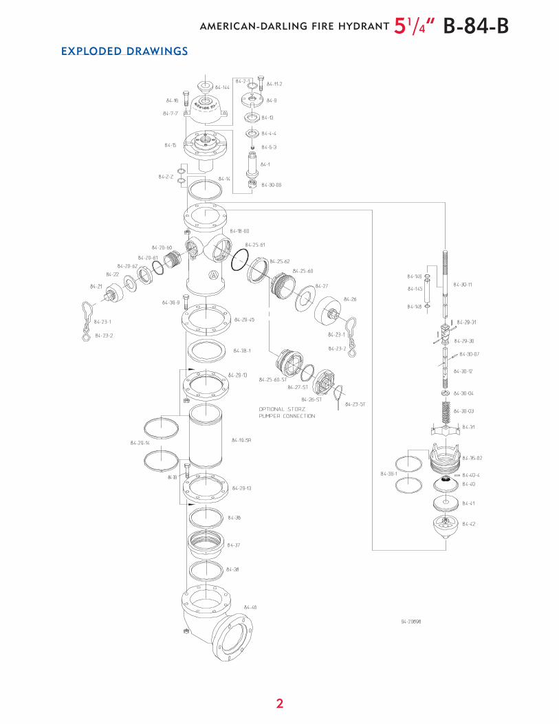
EXPLODED DRAWINGS/DIMENSIONS
51/4” B-84-BAMERICAN-DARLING FIRE HYDRANT
3
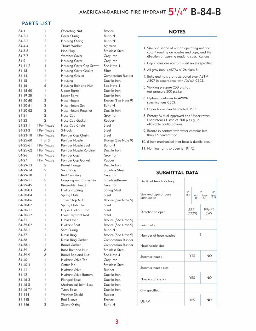
PARTS LIST
51/4” B-84-BAMERICAN-DARLING FIRE HYDRANT
Depth of trench or bury
Size and type of baseconnection
Direction to open
Paint color
Number of hose nozzles
Hose nozzle size
Steamer nozzle
Steamer nozzle size
Nozzle cap chains
City specified
UL-FM
YES NO
4"M.J.
6"M.J. TytonFLG AC
YES NO
1. Size and shape of nut on operating nut and cap, threading on nozzles and caps, and the direction of opening made to specifications.
2. Cap chains are not furnished unless specified.
3. All gray iron is ASTM A126 class B.
4. Bolts and nuts are rustproofed steel ASTMA307 in accordance with AWWA C502.
5. Working pressure 250 p.s.i.g.,test pressure 500 p.s.i.g.
6. Hydrant conforms to AWWAspecifications C502.
7. Upper barrel can be rotated 360°.
8. Factory Mutual Approved and Underwriters Laboratories Listed at 200 p.s.i.g. in allowable configurations.
9. Bronze in contact with water contains less than 16 percent zinc.
10. 6-inch mechanical joint base is ductile iron.
11. Nominal turns to open is 19-1/2.
LEFT RIGHT(CCW) (CW)
2
SUBMITTAL DATA
NOTES
8"M.J.FLG
YES NO
84-1 1 Operating Nut Bronze84-2-1 1 Cover O-ring Buna-N84-2-2 2 Housing O-ring Buna-N84-4-4 1 Thrust Washer Nylatron84-5-3 1 Pipe Plug Stainless Steel84-7-7 1 Weather Cover Gray Iron84-9 1 Housing Cover Gray Iron84-11-2 4 Housing Cover Cap Screw See Note 484-13 1 Housing Cover Gasket Fiber84-14 1 Housing Gasket Composition Rubber84-15 1 Housing Ductile Iron84-16 6 Housing Bolt and Nut See Note 484-18-60 1 Upper Barrel Ductile Iron84-19-SR 1 Lower Barrel Ductile Iron84-20-60 2 Hose Nozzle Bronze (See Note 9)84-20-61 2 Hose Nozzle Seal Buna-N84-20-62 2 Hose Nozzle Retainer Ductile Iron84-21 2 Hose Cap Gray Iron84-22 2 Hose Cap Gasket Rubber84-23-1 1 Per Nozzle Hose Cap Chain Steel84-23-2 1 Per Nozzle S-Hook Steel84-23-18 1 Per Nozzle Pumper Cap Chain Steel84-25-60 1 or 0 Pumper Nozzle Bronze (See Note 9)84-25-61 1 Per Nozzle Pumper Nozzle Seal Buna-N84-25-62 1 Per Nozzle Pumper Nozzle Retainer Ductile Iron84-26 1 Per Nozzle Pumper Cap Gray Iron84-27 1 Per Nozzle Pumper Cap Gasket Rubber84-29-13 2 Barrel Flange Ductile Iron84-29-14 2 Snap Ring Stainless Steel84-29-30 1 Rod Coupling Gray Iron84-29-31 2 Coupling and Cotter Pin Stainless/Bronze84-29-45 1 Breakable Flange Gray Iron84-30-03 1 Hydrant Spring Spring Steel84-30-04 1 Spring Plate Steel84-30-06 1 Travel Stop Nut Bronze (See Note 9)84-30-07 1 Spring Plate Pin Steel84-30-11 1 Upper Hydrant Rod Steel84-30-12 1 Lower Hydrant Rod Steel84-31 1 Drain Lever Bronze (See Note 9)84-35-02 1 Hydrant Seat Bronze (See Note 9)84-36-1 2 Seat O-ring Buna-N84-37 1 Drain Ring Bronze (See Note 9)84-38 2 Drain Ring Gasket Composition Rubber84-38-1 1 Barrel Gasket Composition Rubber84-39 8 Base Bolt and Nut Stainless Steel84-39-9 8 Barrel Bolt and Nut See Note 484-40 1 Hydrant Valve Top Gray Iron84-40-4 1 Cotter Pin Stainless Steel84-41 1 Hydrant Valve Rubber84-42 1 Hydrant Valve Bottom Ductile Iron84-46-2 1 Flanged Base Ductile Iron84-46-5 1 Mechanical Joint Base Ductile Iron84-46-TY 1 Tyton Base Ductile Iron84-144 1 Weather Shield Rubber84-145 1 Rod Sleeve Bronze84-146 2 Sleeve O-ring Buna-N
4
Fire hydrants shall meet or exceed
AWWA C502, latest revision. Rated
working pressure shall be 250 p.s.i.g.,
test pressure shall be 500 p.s.i.g., and
hydrants shall include the following
specific design criteria:
The main valve closure shall be of the
compression type. Traffic feature to be
designed for easy 360º rotation of
nozzle section during field installation.
The main valve opening shall not
be less than 5-1/4” and be designed
so that removal of all working parts
can be accomplished without
excavating. The bronze seat shall be
threaded into mating threads of
bronze. The draining system of the
hydrant shall be bronze and positively
activated by the main operating rod.
Hydrant drains shall close completely
after no more than three turns of the
operating nut. There shall be a
minimum of two internal ports and
four drain port outlets to the exterior of
the hydrant. Drain shutoff to be by
direct compression closure.
Hydrant barrels shall be made of
centrifugally cast ductile iron.
Friction loss not to exceed 3.0 p.s.i.g.
at 1000 gpm through 4-1/2” pumper
nozzle. Hydrants shall be equal to
American Flow Control’s American-
Darling 5-1/4” B-84-B.
Spring-Loaded Multiport Drains
There are two drain ports and four
drain outlets as a standard feature on the
B-84-B hydrant. The rod spring assures
drains close after approximately three
turns of the operating nut. This important
safety feature prevents wash-outs that
can happen on hydrant designs that do
not have this important feature.
• Positive compression,fast-closing drains
• Travel stop located in top of hydrant • Bronze-to-bronze seating
• Short, lightweight,disassembly wrench
• Easy 360° rotation of nozzle section• All bases are epoxy-coated ductile iron
• Centrifugally cast, high-strength ductile iron lower and upper barrel
• Sealed lubrication chamber• Lower valve ball is epoxy coated
The B-84-B hydrant has these standard features:
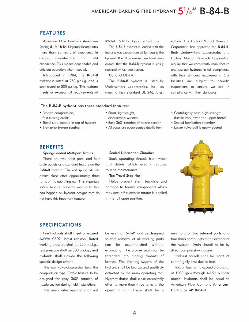
American Flow Control’s American-
Darling 5-1/4” B-84-B hydrant incorporates
more than 80 years of experience in
design, manufacture, and field
experience. This means dependable and
efficient operation when needed.
Introduced in 1984, the B-84-B
hydrant is rated at 250 p.s.i.g. and is
seat tested at 500 p.s.i.g. This hydrant
meets or exceeds all requirements of
AWWA C502 for dry-barrel hydrants.
The B-84-B hydrant is loaded with the
features you expect from a high-quality fire
hydrant. The all bronze seat and drain ring
ensure that the B-84-B hydrant is easily
repaired by just one person.
Optional UL-FM
The B-84-B hydrant is listed by
Underwriters Laboratories, Inc., as
meeting their standard UL 246, latest
edition. The Factory Mutual Research
Corporation has approved the B-84-B.
Both Underwriters Laboratories and
Factory Mutual Research Corporation
require that we consistently manufacture
and test our hydrants in full compliance
with their stringent requirements. Our
facilities are subject to periodic
inspections to ensure we are in
compliance with their standards.
BENEFITS
SPECIFICATIONS
FEATURES
Sealed Lubrication Chamber
Seals operating threads from water
and debris which greatly reduces
routine maintenance.
Top Travel Stop Nut
Helps prevent stem buckling and
damage to bronze components which
may occur if excessive torque is applied
in the full open position.
51/4” B-84-BAMERICAN-DARLING FIRE HYDRANT
AFC-4/06-6M
Distributed By:
American-Darling ValveP.O. Box 2727
Birmingham, AL 35202-2727Phone: 1-800-326-7861
Fax: 1-800-610-3569
e-mail: [email protected]
Waterous Company125 Hardman Avenue South
South St. Paul, MN 55075-2421Phone: 1-888-266-3686
Fax: 1-800-601-2809
e-mail: [email protected]
American Flow Control American-Darling Valve and Waterous
A Division of American Cast Iron Pipe Company
www.acipco.com/afc