american society of civil engineers design, … 45-46-47 stormwater...a s c e s t a n d a r d...
TRANSCRIPT

A S C E S T A N D A R D ASCE/EWRI 45-XX
ASCE/EWRI 46-XX ASCE/EWRI 47-XX
American Society of Civil Engineers
Standard Guidelines for the Design, Installation, and Operation of Urban Stormwater Systems
Three Complete Standards
Standard Guidelines for the Design of Urban Stormwater Systems ASCE/EWRI 45-XX Standard Guidelines for the Installation of Urban Stormwater Systems ASCE/EWRI 46-XX
Standard Guidelines for the Operation and Maintenance of Urban Stormwater Systems ASCE/EWRI 47-XX
This document uses both the International System of Units (SI) and customary units.
Urban Drainage Standards Committee of the Standards Development Council of the Environmental and Water Resources Institute of the American Society of Civil Engineers
Published by the American Society of Civil Engineers
Public
Com
ment D
raft D
o Not
Use or
Cite
Library of Congress Cataloging-in-Publication data
ASCE/EWRI 45-xx (Standard guidelines for the design of urban stormwater systems), ASCE/EWRI 46-xx (Standard guidelines for the installation of urban stormwater systems), and ASCE/EWRI 47-xx (Standard guidelines for the operation and maintenance of urban stormwater systems).
p. cm. “ASCE/EWRI 45-xx.” ISBN 0-7844-0811-4 11. Storm sewers—Standards. I. American Society of Civil Engineers.
TD665.A83 2005
628'.212 ' 0218—dc22 2005022933
Published by American Society of Civil Engineers 1801 Alexander Bell Drive Reston, Virginia 20191 www.pubs.asce.org
Any statements expressed in these materials are those of the individual authors and do not necessarily represent the views of ASCE, which takes no responsibility for any statement made herein. No reference made in this publication to any specific method, product, process or service constitutes or implies an endorsement, recommendation, or warranty thereof by ASCE. ASCE makes no representation or warranty of any kind, whether express or implied, concerning the accuracy, completeness, suitability, or utility of any information, apparatus, product, or process discussed in this publication, and assumes no liability therefore. This information should not be used without first securing competent advice with respect to its suitability for any general or specific application. Anyone utilizing this information assumes all liability arising from such use, including but not limited to infringement of any patent or patents.
ASCE and American Society of Civil Engineers—Registered in U.S. Patent and Trademark Office.
Photocopies: Authorization to photocopy material for internal or personal use under circumstances not falling within the fair use provisions of the Copyright Act is granted by ASCE to libraries and other users registered with the Copyright Clearance Center (CCC) Transactional Reporting Service, provided that the base fee of $25.00 per article is paid directly to CCC, 222 Rosewood Drive, Danvers, MA 01923. The identification for this book is 07844-0806-8/06/ $25.00. Requests for special permission or bulk copying should be addressed to Permissions & Copyright Dept., ASCE.
Copyright © 2014 by the American Society of Civil Engineers. All Rights Reserved. ISBN 0-7844-0811-4 1 (print)
Manufactured in the United States of America.
Public
Com
ment D
raft D
o Not
Use or
Cite

STANDARDS
In April 1980, the Board of Direction approved ASCE Rules for Standards Committees to govern the writing and maintenance of standards developed by the Society. All such standards are developed by a consensus standards process managed by the Codes and Standards Activities Committee. The consensus process includes balloting by the Balanced Standards Committee, which is comprised of Society members and nonmembers, balloting by the membership of ASCE as a whole, and balloting by the public. All standards are updated or reaffirmed by the same process at intervals not exceeding five years.
The following standards have been issued: ANSI/ASCE 1-82 N-725 Guideline for Design and Analysis of Nuclear Safety Related Earth Structures ANSI/ASCE 2-91 Measurement of Oxygen Transfer in Clean Water ANSI/ASCE 3-91 Standard for the Structural Design of Composite Slabs and ANSI/ASCE 9-91 Standard
Practice for the Construction and Inspection of Composite Slabs ASCE 4-98 Seismic Analysis of Safety-Related Nuclear Structures Building Code Requirements for Masonry Structures (ACI 530-02/ASCE 5-02/TMS 402-02) and Specifications
for Masonry Structures (ACI 530.1-02/ASCE 6-02/TMS 602-02) ASCE/SEI 7-05 Minimum Design Loads for Buildings and Other Structures ANSI/ASCE 8-90 Standard Specification for the Design of Cold-Formed Stainless Steel Structural Members ANSI/ASCE 9-91 listed with ASCE 3-91 ASCE 10-97 Design of Latticed Steel Transmission Structures SEI/ASCE 11-99 Guideline for Structural Condition Assessment of Existing Buildings ASCE 12-13, 13-13, 14-13 Standard Guidelines for the Design, Installation, and Operation and Maintenance of
Urban Subsurface Drainage ASCE 15-98 Standard Practice for Direct Design of Buried Precast Concrete Pipe Using Standard Installations
(SIDD) ASCE 16-95 Standard for Load Resistance Factor Design (LRFD) of Engineered Wood Construction ASCE 17-96 Air-Supported Structures ASCE 18-96 Standard Guidelines for In-Process Oxygen Transfer Testing ASCE 19-96 Structural Applications of Steel Cables for Buildings ASCE 20-96 Standard Guidelines for the Design and Installation of Pile Foundations ASCE 21-96 Automated People Mover Standards—Part 1 ASCE 21-98 Automated People Mover Standards—
Part 2 ASCE 21-00 Automated People Mover Standards—Part 3 SEI/ASCE 23-97 Specification for Structural Steel Beams with Web Openings ASCE/SEI 24-05 Flood Resistant Design and Construction ASCE 25-97 Earthquake-Actuated Automatic Gas Shut-Off Devices ASCE 26-97 Standard Practice for Design of Buried Precast Concrete Box Sections ASCE 27-00 Standard Practice for Direct Design of Precast Concrete Pipe for Jacking in Trenchless
Construction ASCE 28-00 Standard Practice for Direct Design of Precast Concrete Box Sections for Jacking in Trenchless
Construction SEI/ASCE/SFPE 29-99 Standard Calculation Methods for Structural Fire Protection SEI/ASCE 30-00 Guideline for Condition Assessment of the Building Envelope SEI/ASCE 31-03 Seismic Evaluation of Existing Buildings SEI/ASCE 32-01 Design and Construction of Frost-Protected Shallow Foundations EWRI/ASCE 33-01 Comprehensive Transboundary International Water Quality Management Agreement EWRI/ASCE 34-01 Standard Guidelines for Artificial Recharge of Ground Water EWRI/ASCE 35-01 Guidelines for Quality Assurance of Installed Fine-Pore Aeration Equipment
Public
Com
ment D
raft D
o Not
Use or
Cite

CI/ASCE 36-01 Standard Construction Guidelines for Microtunneling SEI/ASCE 37-02 Design Loads on Structures During Construction CI/ASCE 38-02 Standard Guideline for the Collection and Depiction of Existing Subsurface Utility Data EWRI/ASCE 39-03 Standard Practice for the Design and Operation of Hail Suppression Projects ASCE/EWRI 40-03 Regulated Riparian Model Water Code ASCE/EWRI 42-04 Standard Practice for the Design and Operation of Precipitation Enhancement Projects ASCE/SEI 43-05 Seismic Design Criteria for Structures, Systems, and Components in Nuclear Facilities ASCE/EWRI 44-05 Standard Practice for the Design and Operation of Supercooled Fog Dispersal Projects
Public
Com
ment D
raft D
o Not
Use or
Cite

Standard ASCE 45-XX / DRAFT 5
Public
Com
ment D
raft D
o Not
Use or
Cite

Standard ASCE 45-XX / DRAFT 6
CONTENTS
Standard Guidelines for the Design of Urban Stormwater Systems, ASCE/EWRI 45-XX ...... 1
Standard Guidelines for the Installation of Urban Stormwater Systems, ASCE/EWRI 46-XX
Standard Guidelines for the Operation and Maintenance of Urban Stormwater Systems,
ASCE/EWRI 47-XX .................................................................................................................
Index ..........................................................................................................................................
Public
Com
ment D
raft D
o Not
Use or
Cite

Standard ASCE 45-XX / DRAFT 7
A S C E S T A N D A R D ASCE/EWRI 45-XX
American Society of Civil Engineers
Standard Guidelines for the Design of Urban Stormwater Systems
Public
Com
ment D
raft D
o Not
Use or
Cite

Standard ASCE 45-XX / DRAFT 8
CONTENTS
FOREWORD........................................................................................................................ ACKNOWLEDGMENTS ................................................................................................... 1 Scope ......................................................................................................................... 1.1 Applicable Standards .................................................................................. 2 Definitions ................................................................................................................. 2.1 General ....................................................................................................... 2.2 Terms .......................................................................................................... 3 Site Analysis ............................................................................................................ 3.1 Basic Requirements ................................................................................... 3.1.1 Topography ..................................................................................... 3.1.2 Geography ....................................................................................... 3.1.3 Water Table ..................................................................................... 3.1.4 Geology ........................................................................................... 3.1.5 Water Source ................................................................................... 3.1.6 Soil Information ............................................................................. 3.1.7 Environmental Factors .................................................................... 3.1.8 Physical Constraints ........................................................................ 3.1.9 Land Use ......................................................................................... 3.1.10 Zoning Regulations ........................................................................ 3.1.11 Other Governmental Regulations ................................................... 4 Hydrology ................................................................................................................. 4.1 Quantity ...................................................................................................... 4.1.1 Design Points and Return Periods .................................................. 4.1.2 Runoff Determination Methods ..................................................... 4.1.3 Design Rainfall .............................................................................. 4.1.4 Rainfall Abstraction ....................................................................... 4.1.5 Runoff Hydrographs ....................................................................... 4.1.6 Rational Method.............................................................................. 4.1.7 Time of Concentration ................................................................... 4.1.8 Hydrograph ..................................................................................... 4.1.9 Calibration ...................................................................................... 4.1.10 Historical Information ..................................................................... 4.2 Water Quality ............................................................................................. 4.2.1 Pollutant Sources ........................................................................... 4.2.2 Water Quality Effects .................................................................... 4.3 Rainfall Runoff Computer Models ................................................................ 5 Nonstructural Considerations..................................................................................... 5.1 Floodplains .....................................................................................................
Public
Com
ment D
raft D
o Not
Use or
Cite

Standard ASCE 45-XX / DRAFT 9
5.2 Wetlands ........................................................................................................ 5.3 Forests and Riparian Buffers ........................................................................ 5.4 Stream Bank Assessment .............................................................................. 5.5 Site Planning ................................................................................................. 6 System Configuration ................................................................................................ 6.1 Collection System Types ............................................................................ 6.1.1 Pipes or Conduits ............................................................................ 6.1.2 Inlet Structures ................................................................................ 6.1.3 Drainage Ways ................................................................................ 6.1.4 Streets ............................................................................................. 6.1.5 Flow Controls.................................................................................. 6.1.6 Retention/Detention Facilities ........................................................ 6.2 Special Structures ....................................................................................... 6.2.1 Pumping Stations ........................................................................... 6.2.2 Vaults ............................................................................................. 6.2.3 Manholes ........................................................................................ 6.2.4 Cleanouts......................................................................................... 6.2.5 Equipment Access Shafts ............................................................... 6.3 Applications ............................................................................................... 6.3.1 Location Requirements ................................................................... 6.3.2 Site Restrictions ............................................................................. 7 Hydraulic Design ...................................................................................................... 7.1 Hydraulic Principles.................................................................................... 7.1.1 Flow Classification ......................................................................... 7.1.2 Energy Principle.............................................................................. 7.1.3 Momentum Principle ...................................................................... 7.1.4 Conservation of Mass ..................................................................... 7.2 Elements of Hydraulic Analysis ................................................................ 7.2.1 Normal Depth.................................................................................. 7.2.2 Water Surface Profile Classification ............................................... 7.2.3 Hydraulic Jump ............................................................................... 7.2.4 Hydraulic Head Losses Because of Friction ................................... 7.2.5 Form Losses ................................................................................... 7.3 Hydraulic Structures ................................................................................... 7.3.1 Stormwater Inlets ........................................................................... 7.3.2 Culverts ........................................................................................... 7.3.3 Bridges ........................................................................................... 7.3.4 Spillways and Drop Structures........................................................ 7.3.5 Energy Dissipation and Outlet Structures ...................................... 7.3.6 Open Channel Linings and Structures ............................................ 7.3.7 Pumps ................................................................................................. 7.4 Hydraulic Analysis Procedures .................................................................. 7.5 Flow Routing .............................................................................................. 7.5.1 Muskingum Method or the Kinematic Wave Technique ............... 7.5.2 Modified Kinematic Wave Routing Method ................................. 7.5.3 Modified Puls Method ................................................................... 7.6 Computer Models........................................................................................ 8 Structural Design of Stormwater Systems ................................................................
Public
Com
ment D
raft D
o Not
Use or
Cite

Standard ASCE 45-XX / DRAFT 10
8.1 Loading ...................................................................................................... 8.1.1 Dead Loads ..................................................................................... 8.1.2 Live Loads ...................................................................................... 8.1.3 Construction Loads ......................................................................... 8.1.4 Jacking Loads.................................................................................. 8.1.5 Other Loads ..................................................................................... 8.2 Embedment . ............................................................................................... 8.3 Pipe and Culvert Structural Requirements .................................................. 8.3.1 Concrete Pipe ................................................................................. 8.3.2 Flexible Pipe ................................................................................... 8.3.3 Box Culverts ................................................................................... 8.3.4 Pipe Joints ....................................................................................... 8.3.5 Trenchless Technology ................................................................... 8.3.6 Geosynthetics .................................................................................. 8.4 Pipe Appurtenances and Other Structures ................................................. 8.4.1 Open Channel Linings ................................................................... 8.4.2 Open Channel Structures ............................................................... 8.4.3 Pipe Appurtenances ....................................................................... 8.4.4 Other Structures .............................................................................. 9 Materials ............................................................................................................ 9.1 Environmental Considerations .................................................................... 9.2 Economic Considerations ........................................................................... 9.3 Pipe and Culvert Materials ......................................................................... 9.3.1 Rigid Pipe ....................................................................................... 9.3.2 Metal Pipe ...................................................................................... 9.3.3 Thermoplastic Pipe ........................................................................ 9.3.4 Box Culverts .................................................................................. 9.3.5 Pipe Joints ...................................................................................... 9.4 Other Materials and Products ..................................................................... 10 Regulations and Permits ............................................................................................ 10.1 Regulations ................................................................................................. 10.1.1 Urban Stormwater Systems ............................................................ 10.1.2 Urban Surface Drainage Systems .................................................. 10.2 Permits ....................................................................................................... 10.2.1 Contract Documents........................................................................ 10.2.2 Terms and Provisions ...................................................................... 11 References ................................................................................................................. 11.1 Cited References ......................................................................................... 11.2 General References .................................................................................... Index ....................................................................................................................................
Public
Com
ment D
raft D
o Not
Use or
Cite

Standard ASCE 45-XX / DRAFT 11
FOREWORD
The Board of Direction approved revisions to the ASCE Rules for Standards Committees to govern the writing and maintenance of standards developed by ASCE. All such standards are developed by a consensus standards process managed by the ASCE Codes and Standards Committee (CSC). The consensus process includes balloting by a balanced standards committee and reviewing during a public comment period. All standards are updated or reaffirmed by the same process at intervals between five and 10 years. Requests for formal interpretations shall be processed in accordance with Section 7 of ASCE Rules for Standards Committees, which are available at www.asce.org. Errata, addenda, supplements, and interpretations, if any, for these standard guidelines also can be found at www.asce.org.
The Standard Guidelines for the Design of Urban Stormwater Systems is a companion to the Standard Guidelines for the Installation of Urban Stormwater Systems and Standard Guidelines for the Operation and Maintenance of Urban Stormwater Systems. These standard guidelines were developed by the Urban Drainage Standards Committee, which is responsible to the Environmental and Water Resources Institute of the American Society of Civil Engineers.
The provisions of this document are written in permissive language and, as such, offer to the user a series of options or instructions but do not prescribe a specific course of action. Significant judgment is left to the user of this document.
These standard guidelines may involve hazardous materials, operations, and equipment. These standard guidelines do not purport to address the safety problems associated with its application. It is the responsibility of whoever uses these standard guidelines to establish appropriate safety and health practices and to determine the applicability of regulatory and nonregulatory limitations.
These standard guidelines have been prepared in accordance with recognized engineering principles and should not be used without the user’s competent knowledge for a specific application. The publication of these standard guidelines by ASCE is not intended to warrant that the information contained therein is suitable for any general or specific use, and ASCE takes no position respecting the validity of patent rights. The user is advised that the determination of patent rights or risk of infringement is entirely his or her own responsibility.
Public
Com
ment D
raft D
o Not
Use or
Cite
Standard ASCE 45-XX / DRAFT 12
ACKNOWLEDGMENTS
The American Society of Civil Engineers (ASCE) acknowledges the work of the Urban Drainage Standards Committee of the Environmental and Water Resources Institute of ASCE (EWRI of ASCE).
This group comprises individuals from many backgrounds, including consulting engineering, research, construction industry, education, and government. The individuals who serve on the Urban Drainage Standards Committee are William Curtis Archdeacon, P.E., R.L.S., Past Chair
Kathlie Jeng-Bulloch, Ph.D., P.E., D.WRE, CFM, M.ASCE, Chair William P. Bulloch, P.E., M.ASCE Christopher B. Burke, Ph.D., P.E., D.WRE, F.ASCE James C.-I. Chang, Ph.D., P.E. Richard Field, P.E., D.WRE, BCEE, M.ASCE Robert S. Giurato Jeffrey S. Glenn, P.E., D.WRE, CFM, F.ASCE
S. David Graber, P.E., F.ASCE, Vice Chair and Corresponding Editor Jay M. Herskowitz, P.E., M.ASCE Conrad G. Keyes, Jr., Ph.D., P.E., L.S., D.WRE, Dist.M.ASCE James H. Lenhart, Jr., P.E., D.WRE, M.ASCE Lawrence M. Magura, P.E., M.ASCE, Secretary Garvin J. Pederson, P.E., M.ASCE Anthony N. Tafuri, P.E., D.WRE, M.ASCE Kenneth E. Waite, P.E., M.ASCE Keh-Han Wang, Ph.D., M.ASCE William J. Weaver, P.E., M.ASCE Donald E. Woodward, P.E., F.ASCE
The corresponding editor recognizes the following committee members who were particularly helpful in updating the standard guidelines: Jeffrey S. Glenn, Conrad G. Keyes, Jr., James H. Lenhart, Kenneth E. Waite, William J. Weaver, and Donald E. Woodward.
Public
Com
ment D
raft D
o Not
Use or
Cite

Standard ASCE 45-XX / DRAFT 13
CHAPTER 1 SCOPE
The intent of these standard guidelines is to present design guidance for urban stormwater systems. It updates ASCE/EWRI 45-05 Standard Guidelines for the Design of Urban Stormwater Systems with material developed within the past eight years. The collection, management, and conveyance of urban surface waters are within the purview of these standard guidelines for applications such as airports, roads, and other transportation systems; and industrial, commercial, residential, and recreation areas. This document is intended for guidance during the design phase.
These standard guidelines do not address applications, such as agricultural drainage, landfills, and injection systems. Combined Sewer Overflows (CSOs) also are not addressed, because they are environmentally unacceptable as a new standard of practice in the United States.
Both SI units and customary units are used throughout the guidelines for the narrative, figures, and tables. The formulas are written in dual units or written separately to show the use of either SI units or customary units.
1.1 APPLICABLE STANDARDS The standards listed as follows are available from the offices of the cited organization: American Association of State Highway Officials (AASHTO) in Washington DC; American Society of Civil Engineers (ASCE) in Reston, VA; American National Standards Institute/American Water Works Association documents from AWWA in Denver; and ASTM International (ASTM) in West Conshohocken, PA. The standards are mentioned in these guidelines at the sections in which they are applicable.
The ASTM standard and comparable AASHTO standard for a product are commonly identical; however, there may be some differences, especially when AASHTO standards lag behind ASTM standard revisions. If there is a separate metric edition of a standard, its designation includes the letter M (e.g., C507M).
American Association of State Highway and Transportation Officials (AASHTO), Standard Specifications for Highway Bridges, AASHTO HB-17, 17th Ed., 2002. AASHTO, Standard Specification for Classification of Soils and Soil-Aggregate Mixtures for Highway
Construction Purposes, M145-91, 2004. AASHTO, Standard Specification for Bituminous Coated Corrugated Metal Culvert Pipe and Pipe, M190-04,
2004. AASHTO, Standard Specification for Corrugated Aluminum Alloy Structural Plate for Field-Bolted Pipe, Pipe-Arches, and Arches, M219-92, 2004. AASHTO, Standard Practice for Corrugated Polyethylene Drainage Pipe, AASHTO M252-09, 2009. AASHTO, Standard Specification for Precast Reinforced Concrete Box Sections for Culverts, Storm Drains,
and Sewers, M259/M259M-11, 2011. AASHTO, Standard Specification for Precast Reinforced Concrete Box Sections for Culverts, Storm Drains,
and Sewers with Less Than 2 Feet (0.6 m) of Cover Subjected to Highway Loadings, M273/M273M-11, 2011.
Public
Com
ment D
raft D
o Not
Use or
Cite

Standard ASCE 45-XX / DRAFT 14
AASHTO, Standard Practice for Corrugated Polyethylene Pipe 300- to 1500-mm (12- to 60-in.), M294-10, 2010.
AASHTO, Standard Specification for Poly(Vinyl Chloride) (PVC) Profile Wall Drain Pipe and Fittings Based on Controlled Inside Diameter, M304-11, 2011.
AASHTO, Standard Method of Test for Moisture-Density Relations of Soils Using a 2.5-kg (5.5-lb) Rammer and a 305-mm (12-in.) Drop, T 99-10, 2010.
American National Standards Institute, Inc./Hydraulic Institute (ANSI/HI) (1998). American National Standard for Pump Intake Design, Hydraulic Institute, Parsippany, New Jersey.
American Society of Civil Engineers (ASCE), Standard Practice for Direct Design of Buried Precast Concrete Pipe Using Standard Installations, ASCE Standard 15-98, ASCE, 1998.
ASCE, Standard Practice for Direct Design of Precast Concrete Box Sections, Standard 26-97, 1997. ASCE, Standard Practice for Direct Design of Precast Concrete Pipe for Jacking in Trenchless Construction,
Standard 27-00, 2000. ASCE, Standard Practice for Direct Design of Precast Concrete Box Sections for Jacking in Trenchless
Construction, Standard 28-00, 2000. ASCE, Comprehensive Transboundary Water Quality Management Agreement, Standard 33-09, 2009. ASTM International (ASTM), Standard Specification for Corrugated Steel Structural Plate, Zinc-Coated, for
Field-Bolted Pipe, Pipe-Arches, and Arches, A761/761M-04, 2009. ASTM, Standard Practice for Structural Design of Corrugated Steel Pipe, Pipe-Arches, and Arches for Storm
and Sanitary Sewers and Other Buried Appurtenances, A796/A796M-10, 2010. ASTM, Standard Specification for Corrugated Steel Box Culverts, A964/A964M-03, 2011. ASTM, Standard Specification for Composite Ribbed Steel Pipe, Precoated and Polyethylene Lined for Gravity
Flow Sanitary Sewers, Storm Sewers, and Other Special Applications, A978/A978M-11, 2011. ASTM, Standard Specification for Corrugated Aluminum Alloy Structural Plate for Field-Bolted Pipe, Pipe-
Arches, and Arches, B746/B746M-02, 2012. ASTM, Standard Specification for Nonreinforced Concrete Sewer, Storm Drain, and Culvert Pipe, C14-
07/C14M-07, 2007. ASTM, Standard Specification for Concrete Pipe for Irrigation or Drainage, C118-05a/C118M-05a, 2005. ASTM, Standard Specification for Reinforced Concrete Low-Head Pressure Pipe, C361-08/C361M-08, 2008. ASTM, Standard Specification for Nonreinforced Concrete Irrigation Pipe with Rubber Gasket Joints, C505-
05a/C505M-05a, 2005. ASTM, Standard Specification for Reinforced Concrete Elliptical Culvert, Storm Drain, and Sewer Pipe, C507-
11/C507M-11, 2011. ASTM, Standard Specification for Nonreinforced Concrete Specified Strength Culvert, Storm Drain, and Sewer
Pipe, C985-04/C985M-04, 2010. ASTM, Standard Specification for Precast Reinforced Concrete Monolithic Box Sections for Culverts, Storm
Drains, and Sewers, C1433/C1433M-10, 2010. ASTM, Standard Specification for Precast Reinforced Concrete Monolithic Box Sections for Culverts, Storm
Drains, and Sewers Designed According to AASHTO LRFD, C1577-13. ASTM, Standard Specification for Joints for Concrete Box, Using Rubber Gaskets, C1677-11A. ASTM, Standard Test Methods for Laboratory Compaction Characteristics of Soil Using Standard Effort (12
400 ft-lbf/ft3 (600 kN-m/m3)), D698-12, 2012. ASTM, Standard Practice for Underground Installation of Thermoplastic Pipe for Sewers and Other Gravity-
Flow Applications, D2321-09, 2009. ASTM, Standard Practice for Classification of Soils for Engineering Purposes (Unified Soil Classification
System), D2487, 2011. ASTM, Standard Specification for Poly(Vinyl Chloride) (PVC) Sewer Pipe and Fittings, D2729-03, 2003. ASTM, Standard Specification for Type PSM Poly(Vinyl Chloride) (PVC) Sewer Pipe and Fittings, D3034-08,
2008. ASTM, Standard Practice for Corrugated Polyethylene (PE) Pipe and Fittings, F405-05, 2005. ASTM, Standard Practice for Large Diameter Corrugated Polyethylene Pipe and Fittings, F667-06, 2006.
Public
Com
ment D
raft D
o Not
Use or
Cite

Standard ASCE 45-XX / DRAFT 15
ASTM, Standard Specification for Poly(Vinyl Chloride) (PVC) Large-Diameter Plastic Gravity Sewer Pipe and Fittings, F679-08, 2008.
ASTM, Standard Specification for Smooth-Wall Poly(Vinyl Chloride) (PVC) Plastic Underdrain Systems for Highway, Airport, and Similar Drainage, F758-95, 2007.
ASTM, Standard Specification for Poly(Vinyl Chloride) (PVC) Profile Gravity Sewer Pipe and Fittings Based on Controlled Inside Diameter, F794-03, 2009.
ASTM, Standard Practice for Smoothwall Polyethylene (PE) Pipe for Use in Drainage and Waste Disposal Absorption Fields, F810-07, 2007.
ASTM, Standard Specification for Coextruded Poly(Vinyl Chloride) (PVC) Plastic Pipe With a Cellular Core, F891-10, 2010.
ASTM, Standard Practice for Polyethylene (PE) Large Diameter Profile Wall Sewer and Drain Pipe, F894-07, 2007.
ASTM, Standard Specification for Poly(Vinyl Chloride) (PVC) Corrugated Sewer Pipe with a Smooth Interior and Fittings, F949-10, 2010.
ASTM, Standard Practice for Rehabilitation of Existing Pipelines and Conduits by the Inversion and Curing of a Resin-Impregnated Tube, F1216-09, 2009.
ASTM, Standard Guide for Use of Maxi-Horizontal Directional Drilling for Placement of Polyethylene Pipe or Conduit Under Obstacles, Including River Crossings, F1962-11, 2011.
ASTM/AASHTO, Standard Specification for Reinforced Concrete Culvert, Storm Drain, and Sewer Pipe, ASTM C76/C76M-11, ASTM, 2011/AASHTO M170-10/M170M-09, AASHTO, 2010.
ASTM/AASHTO, Standard Specification for Concrete Drain Tile, ASTM C412/C412M-05a, ASTM, 2005/AASHTO M178/M178M—07, AASHTO, 2007.
ASTM/AASHTO, Standard Specification for Perforated Concrete Pipe, ASTM C444/C444M-03, AASHTO, 2009 /AASHTO M175/M175M-05, AASHTO, 2005.
ASTM/AASHTO, Standard Specification for Reinforced Concrete Arch Culvert, Storm Drain, and Sewer Pipe, ASTM C506/C506M-11, ASTM, 2011/AASHTO M206/M206M-10, AASHTO, 2010.
ASTM/AASHTO, Standard Specification for Reinforced Concrete Elliptical Culvert, Storm Drain, and Sewer Pipe, C507/C507M-10b, ASTM, 2010/AASHTO M207/ M207M-10, AASHTO, 2010.
ASTM /AASHTO, Standard Specification for Porous Concrete Pipe, ASTM C654/C654M-05a, ASTM, 2005/AASHTO M176/M176M—07, AASHTO, 2007.
ASTM /AASHTO, Standard Specification for Reinforced Concrete D-Load Culvert, Storm Drain and Sewer Pipe, ASTM C655/C655M-09, ASTM, 2009/AASHTO M242/M242M-08, AASHTO, 2008.
ASTM/AASHTO, Standard Specification for Corrugated Steel Pipe, Metallic-Coated for Sewers and Drains, ASTM A760/A760M-10, ASTM, 2010/AASHTO M36-03, AASHTO, 2003.
ASTM/AASHTO, Standard Specification for Corrugated Steel Pipe, Polymer Precoated for Sewers and Drains, ASTM A762/A762M-08, ASTM, 2008/AASHTO M245-00, AASHTO, 2004.
ASTM/AASHTO, Standard Specification for Corrugated Aluminum Pipe for Sewers and Drains, ASTM B745/B745M-97, ASTM, 2005/AASHTO M196-92, AASHTO, 2004.
ASTM/AASHTO, Standard Specification for Acrylonitrile-Butadiene-Styrene (ABS) and Poly(Vinyl Chloride) (PVC) Composite Sewer Piping, ASTM D2680-01, 2009/AASHTO M264-03, AASHTO, 2003.
Public
Com
ment D
raft D
o Not
Use or
Cite

Standard ASCE 45-XX / DRAFT 16
CHAPTER 2 DEFINITIONS
2.1 GENERAL
This section defines specific terms for use in these standard guidelines. The references listed in Section 11 may be useful to augment understanding the terms.
2.2 TERMS
AOS—Apparent opening size of geotextile. Aquifer—Geologic formation or group of formations through which water flows or within which water is
stored. Base Drainage System—Permeable drainage blanket under a paved roadway, parking area, and so on. CBR—California Bearing Ratio. Chimney Drain—Subsurface interceptor drain frequently used in dams, embankments, and similar
constructions to control seepage within the earthen structure. Collector Drain—Product or system intended for collecting and transporting water. Colloidal Fines—Clay particles smaller than two microns. Drainable Water—Water that readily drains from soil under the influence of gravity. Evapotranspiration—Combined process of moisture evaporation from the soil and transpiration from plants. Frost Action—Movement of soil caused by freezing and thawing of soil moisture. Geocomposite—Geosynthetic materials comprised of different combinations of geotextiles, geomembranes,
geonets, and other materials for collecting and transporting water while maintaining soil stability. Geology—Natural subsurface soil and rock formations. Geomembrane—Sheet material intended to form an impervious barrier. Geonet—A geosynthetic material consisting of integrally connected parallel sets of ribs overlying similar sets
at various angles for in-plane drainage. Geosynthetic—Synthetic material or structure used as an integral part of a project, structure, or system. Within
this category are surface drainage and water control materials, such as geomembranes, geotextiles, geonets, and geocomposites.
Geotextile—Woven or nonwoven engineered fabric intended to allow the passage of water and limited soil particles.
Hydraulic Conductivity—A measure of the rate with which water moves in a soil or aggregate. When Darcy's Law is applicable, it is equal to the face velocity (the rate of flow divided by the corresponding total cross-sectional area) divided by the hydraulic gradient.
Hydraulic gradient— In porous media, the hydraulic gradient is the rate of change in the sum of pressure head and elevation head (that sum being referred to as piezometric head) per unit distance. In an open channel, the hydraulic gradient equals the slope of the water surface.
Hydrology—Study of the movement of water in nature.
Public
Com
ment D
raft D
o Not
Use or
Cite

Standard ASCE 45-XX / DRAFT 17
Impermeable Barrier Layer—Soil stratum with permeability less than 10% of the average soil permeability between the layer and the ground surface.
Infiltration—Movement of water into the soil. Longitudinal Drainage System—Drainage system essentially parallel to a roadway, parking area, and so on. Perched Water Table—Localized condition of free water held in a pervious stratum because of an underlying
impervious stratum. Percolation—Downward movement of water through soil. Permeability (coefficient of permeability)—Rate at which water passes through a porous medium under unit
hydraulic gradient. Permittivity—Measure of the ability of a geotextile to permit water flow perpendicular to its plane. Phreatic Surface—Upper surface of an unconfined body of groundwater. Relief Drain—Any product or construction that accelerates the removal of drainable subsurface water. Seepage—Movement of drainable water through soil and rock. Sink—Relatively small surface depression that allows surface drainage to enter the subsurface water system. Soil Texture—Relative proportions of sand, silt, and clay particles in a soil mass. Subsurface Water—All water beneath the ground or pavement surface. Usually referred to as groundwater. Transverse Drainage System—Drainage system usually at some angle to a roadway or other paved surface. Water Table—Upper limit of free water in a saturated soil or underlying material.
Public
Com
ment D
raft D
o Not
Use or
Cite

Standard ASCE 45-XX / DRAFT 18
CHAPTER 3 SITE ANALYSIS
Site analysis is a thorough review of existing information on the site and its surrounding area. Additional mapping or data may be required to prepare a proper design and contract documents.
3.1 BASIC REQUIREMENTS
The basic information necessary for the design of urban stormwater management facilities requires investigations of the following areas: topography, geography, water table, geology, water source, soil information, environmental factors, physical constraints, land use, zoning restrictions, and other governmental regulations.
3.1.1 Topography. All site features that could influence the stormwater management facility location, installation, and operation should be considered in the design phase. Topographic mapping of the drainage area documents the runoff paths and contributory areas. A general topographic map of a scale of 1:1,200 or 1:2,400 of the project site and its surrounding area is useful in the preliminary design stage. Surface drainage courses should be identified, particularly with focus on locations where concentrated flows (swales and streams) enter and exit the project work area, right-of-way, or property.
A detailed topographic map at a scale of 1 in. equaling 50 ft or less (1:600 or less) depicting planimetric features such as trees, ponds, ditches, and other existing drainage facilities, culverts and catch basins, buildings, roads, walks, overhead utilities, and surface components of underground utilities is necessary to develop and complete the design. Elevation point data should be accurate to within 0.5 ft (0.15 m) on disturbed areas and 0.2 ft (0.06 m) on hard surfaces. Contour intervals should be no greater than 2 ft (0.6 m).
Additional research of “as-built” underground utility records may be required to avoid conflicts. All site mapping and critical utilities should be field checked prior to construction or use. Vacuum excavation and subsurface utility engineering (ASCE 2002) can be useful methods. 3.1.2 Geography. The design engineer should be sensitive to particular geographic constraints that influence site conditions. Some of these constraints may include coastal areas subject to tidal and storm surge conditions, Karst topography that forms discontinuous drainage patterns, floodplains, mining areas or areas subject to earth movement (earthquake, subsidence, mud slides, permafrost, etc.), or special preservation areas and historic sites. Any of these constraints should be identified prior to beginning design.
Public
Com
ment D
raft D
o Not
Use or
Cite
Standard ASCE 45-XX / DRAFT 19
3.1.3 Water Table. The site may require an evaluation of the underlying water table early in the design phase. The design engineer should know the type, the depth below the surface, and conditions of hydrostatic heads of the water table. Information related to water table fluctuation throughout the year should be evaluated. An understanding of the potential effect of water table response from rainfall, nearby well drawdown, and direction of flow may be appropriate if the water table will be in the proximity of a proposed facility. 3.1.4 Geology. The underlying rock and soil strata may affect the design of the stormwater management facilities in several ways. The design engineer should be aware of the potential effects of foundation seepage, slope stability of cut slopes, settlement, impervious layers, high shrink-swell potential clays, or unstable organic layers.
3.1.5 Water Source. In most cases, concentrated flows (swales and streams) entering the project site from major upstream (off-site) drainage areas are diverted past the stormwater management facility. Large off-site inflow will tend to reduce the effectiveness of both water quantity and quality controls and result in larger and more expensive control structures. An exception to this is the regional stormwater management facility that is designed to handle high volumes of inflow.
3.1.6 Soil Information. Soil type and properties will affect many aspects of design including potential for underground disposal with infiltration systems, embankment material selection, structure foundation support, suitability of permanent storage, and surface stabilization. 3.1.6.1 Soil Classification. Information on soil classification can be presented in accordance with the unified soil classification system (Terzaghi, et al. 1996; ASTM D2487), the U.S. Department of Agriculture textural classification system (USBR 1993), the Natural Resource Conservation Service (NRCS) agricultural soil types and hydrological soil groups, or the AASHTO classification system (AASHTO M145). These classification systems are used to assist the design engineer in estimating engineering properties, such as permeability, shrink-swell potential, densities, and bearing capacity. In addition, some of these classification systems offer guides in engineering uses including suitability for embankments, core or cutoff trenches, road subgrade, filter material, pond liners, and others. The USDA and NRCS classification systems will aid in determination of vegetation support and wetland delineation. 3.1.6.2 Hydraulic Conductivity and Permeability. Hydraulic conductivity or permeability of soil is important for the design of infiltration systems, filter systems, and embankments. In situ permeability tests are most useful for the design of infiltration systems. Several procedures are presented in the U.S. Bureau of Reclamation Drainage Manual (1993a). Laboratory tests on retrieved samples or empirical data on the basis of grain size and soil classification are used for newly placed material and may be modified by suitable safety factors to account for variations between test and in-place material behavior. 3.1.6.3 Strata and Layers. Identification of variation of surface strata may be important to predict foundation seepage, support, or stability. 3.1.6.4 Soil/Water Chemistry. Salinity, corrosive, and pH properties may affect the material selection for outfall pipes and underground structures. Local conditions may suggest the use of coatings for metallic pipe, metallic fixtures on structures, concrete in contact with soil or water, and concrete reinforcement. 3.1.6.5 Temperature. Frost depth and freeze-thaw conditions may cause soil movement and structure or pipe damage. Adequate design allowances and installation depth should be provided in areas where conditions are severe. In general, soils that have a high percentage of silt are most susceptible to frost heaving.
Public
Com
ment D
raft D
o Not
Use or
Cite

Standard ASCE 45-XX / DRAFT 20
3.1.6.6 Soil Testing. Adequate soil data are necessary in the design of stormwater management facilities. Soil data may be available from prior tests. However, most projects will require soil borings and laboratory tests to determine engineering properties and classifications. Standard penetration borings may be supplemented with sample recovery, grain size analysis, Atterberg limits, permeability, and moisture-density laboratory tests. Embankment and foundation design may require shear strength and California Bearing Ratio (CBR) tests. Often the soil data will have a significant influence on the design and cost of construction. Minimizing soil borings or laboratory testing to save design cost generally is not a prudent engineering decision. 3.1.7 Environmental Factors. Some of the major environmental considerations in the design of stormwater management facilities are listed following. These factors should be considered during design to prevent adverse environmental effects to adjacent land, residents, and environmentally sensitive ecosystems. 3.1.7.1 Water Quality. Improvement in runoff water quality is often the intent of the stormwater management facility. In the United States, the Federal Water Pollution Control Act requires that runoff from construction sites and discharges from sites already constructed provide runoff quality control. Generally site-specific water quality data for urban runoff is difficult to obtain because of seasonal and rainfall event variability. Many systems or facility types are designed using empirical criteria, such as a theoretical percent pollutant reduction based on retention time or filter depth. Special consideration may be given to oil-laden pavement runoff in cases, such as parking lots, trucking facilities, or high-volume roads. In these cases, oil water separators and filter systems may be necessary. Also, suspended sediment may be reduced with the use of vegetation strips, structure sumps, or traps. Stormwater management facilities that serve chemical facilities or hazardous waste storage sites require careful attention to containment functions and security. Guidelines for the Physical Security of Water Utilities (56-10) and for Wastewater/Stormwater Utilities (57-10) pertain (ANSI/ASCE/EWRI 56-10 and 57-10, 2011) to security of facilities. 3.1.7.2 Flooding. Stormwater management facilities in areas subjected to flooding require consideration of hydraulic effects because of high tailwater for outlets, embankment stability for drawdown on both faces, additional storage for interior drainage, and outlet control flap or sluice gates. 3.1.7.3 Wetlands. Additional consideration is required for the ecological-environmental aspects of the site when applying artificial drainage to a wetland area. Most wetlands are environmentally sensitive ecosystems. The maintenance of wetlands and their ecosystems is important. Many wetlands filter natural and artificially made pollutants. Changes in the quality or quantity of surface waters entering a wetland can affect this sensitive filtering process adversely and may cause detrimental effects to flora and fauna.
Local, state, and federal governments classify wetlands. Any project associated with a wetland most likely will require permits from local, state, or the federal government or a combination of them. 3.1.7.4 Principal or Primary Aquifers. These aquifers often are tapped as a main water source. The intended use of this water determines the necessity and amount of protection required. If a possibility exists for contamination of the aquifer, mitigating measures should be taken to prevent such contamination. Other design alternatives including relocation of the system or a treatment and monitoring program of the discharge may be necessary to remove the contamination potential. 3.1.7.5 Hydrology. Hydrology describes the movement of water. Development modifies the natural hydrologic cycle, which is a valid concern. The development of surface drainage systems should follow the natural hydrologic cycle as
Public
Com
ment D
raft D
o Not
Use or
Cite

Standard ASCE 45-XX / DRAFT 21
closely as possible. For example, if the natural cycle exists as rainfall percolating into groundwater, then joining surface watercourses, the artificially made cycle should parallel this movement. Not all hydrologic cycles are this simple and thus easily paralleled. It is important to consider the natural or existing hydrologic cycle of the site in the design. 3.1.8 Physical Constraints. Most urban settings have constraints related to existing or planned utilities that should be considered in the design of stormwater management systems. Compatibility of the proposed facility with existing drain systems is critical to any layout. The location of utilities may require special consideration in the design phase to accommodate storm drains, future development, and master planning. 3.1.9 Land Use. Land use is one of the most critical factors in determining the volume, placement, and operations of an impoundment facility. The nature of runoff is determined largely by the upstream land use, both existing and planned. The existing land uses will generally be the primary determining factor in the rate of runoff allowed from a developed impoundment facility. The planned land uses generally will be the primary determining factor for the rate and volume of runoff entering the impoundment facility and its subsequent volume. 3.1.10 Zoning Regulations. Most U.S. communities regulate and control development through zoning regulations. These regulations are specific to each community and, as such, should be investigated and understood prior to design. See Chapter 10, Regulations and Permits, for further discussion. 3.1.11 Other Governmental Regulations. There may be other governmental regulations beyond local Land Use Regulations and Zoning Regulations that may affect other design characteristics of a stormwater system. Some of these may include local design/development standards as well as state or federal regulations. The designer or design engineer should contact and perform research with the appropriate agencies to determine those agencies and regulations that will impact the design characteristics of the facility. See Chapter 10, Regulations and Permits, for further discussion.
Public
Com
ment D
raft D
o Not
Use or
Cite

Standard ASCE 45-XX / DRAFT 22
Chapter 4
HYDROLOGY
Successful design of surface drainage systems requires an understanding of the hydrologic cycle and the
impacts of urbanization. Local stormwater management or storm sewer ordinances may determine the minimum
design criteria.
4.1 QUANTITY
The proper design of stormwater systems is a function of the rate of flow for a specific event. The rate of flow is
expressed in cubic feet per second (ft3/s) or cubic meter per second (m3/s). An example of a specific event is a
10-year storm. The local ordinances may establish the specific event or it may be based on technical
recommendations from the local professional staff. Local surface drainage is designed to handle a specific event
safely with limited flooding of an intersection or nearby properties. Some regulatory jurisdictions require
multiple duration events to establish the design storm.
If detention measures are required for increased peak flow with urban development, then the volume of runoff
must be considered. The volume of runoff normally is expressed in cubic feet (ft3), acre-feet, or cubic meters
(m3). The volume of runoff is the area under the hydrograph for the selected event.
4.1.1 Design Points and Return Periods
The location of design points is a function of the topography and the street layout. The layout should consider
the area to be drained. It should also consider lot lines, street locations, underground utilities, and the direction
of flow within the system. Several layouts should be tried to determine the economical design on the basis of
the local ordinances.
The return period or design interval is a function of the design point. The design interval is the average return
period for the design storm. For example, a 25-year event has a 4% chance of being equaled or exceeded in any
given year. Thus, a 25-year return period is equal to a 4% chance event. Most ordinances specify minimum
design requirements that vary with land use.
Typical design return periods reported in the literature are
• Two to 15 years, with 10 years common for storm sewers in residential areas,
• Ten to 100 years, depending on the economic justification for storm sewers in commercial and high-
value districts.
Public
Com
ment D
raft D
o Not
Use or
Cite

Standard ASCE 45-XX / DRAFT 23
The design return periods established in regulatory ordinances should be viewed as minimum design standards.
It may be appropriate to select a design standard that exceeds these minimums (e.g., for critical community
utilities, major highways, and evacuation routes).
4.1.2 Runoff Determination Methods.
Several methods are available to the designer for determining runoff. These methods include
• Statistical
• Regional
• Transfer
• Rainfall runoff
Also included are rainfall runoff computer models.
4.1.2.1 Statistical Methods.
Statistical methods are used when there are 10 years or more of streamflow records at or nearby the design
point. The result is a statement about the probability of a certain historical flow happening in the future. This
statistical analysis method is outlined in “Guidelines for Determining Flood Flow Frequency” Bulletin 17b
(USGS 1982). This method is used in large contributory areas where sufficient gauge station records are
available.
4.1.2.2 Regional Methods.
The regional method is the correlation of peak rate of runoff of a specific design period with causal or physical
related factors such as watershed area.
Development of regional methods requires stream gauge stations with 10 or more years of record in the same
hydrologic region as the design point. The general form of a typical regional equation is given as
Q = CAxS yI z (Eq. 4-1)
where
Q = peak rate of discharge
C = regional coefficient
A = total drainage area
Public
Com
ment D
raft D
o Not
Use or
Cite

Standard ASCE 45-XX / DRAFT 24
S = slope of the main watercourse
I = impervious area as a percentage of the total watershed.
The values of x, y, and z are coefficients of regression. They depend on the specific physical factors of the
watershed and units of variables used.
One major shortcoming with this method is the assumption that future design conditions can be represented by
historic data. This method is used in large contributory areas where sufficient gauge station records are
available.
4.1.2.3 Transfer Methods.
A discharge of specified design period for a tributary area of known size and runoff characteristics is used to
estimate a discharge of the same design period for a larger or smaller watershed.
Development of a peak discharge using the transfer method involves the following format. The data
requirements are the same as the first two methods:
x
B b
A a
Q AQ A
=
(Eq. 4-2)
where
QA = peak discharge for the known drainage area
QB = peak discharge for the unknown drainage area
Aa = known drainage area
Ab = drainage area for the design point
x = a transfer coefficient.
This method is used in large contributory areas where sufficient gauge station records are available.
4.1.2.4 Rainfall Runoff Methods.
Several rainfall runoff methods are in use today. Two of these methods are the National Resource Conservation
Service (NRCS, formerly SCS – Soil Conservation Service) method and the rational method.
The NRCS method was developed to estimate the impact of urbanization on peak rates of discharge and to
estimate the size of the measures to mitigate the impact of urbanization. The details of the NRCS procedure are
Public
Com
ment D
raft D
o Not
Use or
Cite

Standard ASCE 45-XX / DRAFT 25
given in “Small Watershed Hydrology” WINTR-55 (USDA, 2006), which provides procedures for estimating
the peak rate of runoff, determining the runoff hydrograph and the impact of storage on the hydrograph.
The rational method is probably the most frequently used rainfall runoff method in urban hydrology. The details
of the rational method are explained in 4.1.6.
4.1.3 Design Rainfall.
The rainfall value is a function of the procedure and the design storm selected. The design storm return period is
often specified in the local ordinances. The temporal distribution of the design or the distribution of the rainfall
with time is a function of the procedure used.
The U.S. National Weather Service (NWS) has gathered precipitation data for many years. NWS has published
this information in several documents. These documents include
1. “Rainfall Frequency Atlas of the United States for Durations from 30 Minutes to 24 Hours and Return
Periods from 1 to 100 Years,” Technical Paper 40 (Hershfield 1961).
2. “Precipitation-Frequency Atlas of the Western United States,” Vol. I-XI, NOAA Atlas 2.
3. “Five to 60 Minutes Precipitation Frequency for Eastern and Central United States,” NWS HYDRO-35
(Frederick et al. 1977).
4. “Precipitation-Frequency Atlas of the United States.” Vol. 1-7, NOAA Atlas 14 (Bonnin, et al. 2006).
The U.S. National Climate Data Center (NCDC) can provide precipitation data for National Weather Service
(NWS) stations and for many cooperative gauging stations to use as input for various computer models. Several
state agencies in the United States have published a rainfall frequency atlas for their state. Huff and Angel
(1992) is an example of this type of publication. The NWS has developed intensity-duration-frequency (IDF)
curves for many of the first-order stations in the United States. This information is site specific.
4.1.4 Rainfall Abstraction
Rainfall abstraction is defined as that portion of the rainfall that will be retained on the surface before runoff
occurs. It includes surface depression storage and interception. The volume of surface depression storage is a
function of the soil type, cover or land use, and slope. The volume of interception is a function of the vegetation
type and stage of growth.
Rainfall abstraction normally is incorporated into the peak flow procedure. The rational method incorporates
rainfall abstraction into the “C” value. The NRCS method incorporates rainfall abstraction into the runoff curve
number (CN).
Public
Com
ment D
raft D
o Not
Use or
Cite

Standard ASCE 45-XX / DRAFT 26
Some interception values that have been measured include
TYPE VALUE (in.) VALUE (mm)
Urban 0.01 0.25
Forest Areas 0.56 14.22
Some surface depression storage values that have been measured include
TYPE SLOPE VALUE (in.)
VALUE (mm)
Pavement Steep 0.02 0.51 Pavement Flat 0.06 1.52 Pavement Very Flat 0.135 3.43 Forest Litter 0.3 7.62 Good Pasture 0.2 5.08 Smooth Cultivated Land 0.05– 0.1 1.27–2.54 Lawns 0.1 2.54
4.1.5 Runoff Hydrographs.
A runoff hydrograph is a graphical representation of how flow varies with time at some location during the
design storm. Some methods use the unit hydrograph concept to determine the peak rate of runoff. The shape of
the unit hydrograph varies with watershed characteristics.
Various authors have incorporated a hydrograph with the peak rate estimate developed by the rational equation.
The details of the hydrograph development are explained in 4.1.8.
4.1.6 Rational Method.
The rational method is a common procedure used in the United States for determining a peak discharge for a
given area. The rational method is expressed as follows:
Qp = KCIA (Eq. 4-3)
where
Qp = peak discharge in cfs (m3/s)
C = runoff coefficient
I = rainfall intensity in in./ h (mm/h)
A = drainage area in acres (ha)
K = conversion factor = 1.0 cfs-h/ac-in or in the SI system = 0.00278 m3- h/ha-mm.
Public
Com
ment D
raft D
o Not
Use or
Cite

Standard ASCE 45-XX / DRAFT 27
The designer should use this method with caution. The method applicability is questionable for large
watersheds, and its use should be limited to areas less than 200 acres (80 ha).
4.1.6.1 Assumptions.
The following assumptions have been listed over time for the rational method:
1. Runoff coefficient is constant during the design storm.
2. Watershed area does not change during the design storm.
3. Rainfall is constant for a period at least equal to the time of concentration (Tc).
4. Peak rate of runoff is at a maximum when the rainfall is as long as the time of concentration.
4.1.6.2 Runoff Coefficient.
Runoff coefficients are a function of the land use, soil type, design storm, and slope. Local stormwater
ordinances often specify the runoff coefficients to use.
Typical runoff coefficients are shown in Table 4-1, as well as in other references. The values in this table were
taken from “Design and Construction of Urban Stormwater Management Systems,” ASCE Manual of Practice
No. 77 (ASCE/WEF 1992). These coefficients are applicable for a recurrence interval of 2 to 10 years. Less
frequent events require higher runoff coefficients, because the loss rates are proportionally less for the lower-
frequency storms. For 25-year to 100-year recurrence intervals, the coefficients can be multiplied by 1.1 and
1.2, respectively, and the product cannot exceed 1.0.
Conversions between rational method runoff coefficients and NRCS curve number (CN) values are useful. Such
conversions also provide another method for determining the higher runoff coefficients for lower-frequency
storms. Such conversions can be performed logically (Graber 1992). The runoff coefficients discussed here are
based on the assumption that the design storm does not occur when the ground is frozen. When the drainage
area has more than one cover type, the weighted average runoff coefficient should be used. The weighting
should be based on the area of each cover type.
4.1.7 Time of Concentration.
Time of Concentration (Tc) is the time for excess rainfall to travel from the hydraulically most distant point in
the drainage area to the design point. The types of flow are overland or sheet, shallow concentrated, and open
channel flow. The factors that affect the velocity are slope, roughness, and flow type.
Tc is a sum:
Public
Com
ment D
raft D
o Not
Use or
Cite

Standard ASCE 45-XX / DRAFT 28
Tc = T1 + T2 + … + Tn (Eq. 4-4)
where T1, T2, and Tn are the travel time for the various types of flow in the drainage area. Travel time is equal
to the length of flow divided by the velocity or the following:
𝑇𝑡 = 𝐿3600 𝑉
(Eq. 4-5)
where
Tt = travel time in h
L = flow length in ft (m)
V = velocity in ft /s (m/s).
4.1.7.1 Sheet Flow.
Sheet flow is flow over a plane surface. Usually it occurs in the upper end of a drainage area. With sheet flow,
the friction value (Manning’s n) is a roughness coefficient that includes the effects of raindrop impact, drag over
the plane surface, and transportation of sediment. The n values are for very shallow flow depths of about 0.1 ft
(3.0 cm) or less. Table 4-2 shows some typical n values.
For sheet flow of 300 feet (91.4 m) or less, Manning’s kinematic solution can be used to compute Tt as follows
(Overton and Meadows 1976; SCS 1986).
(Eq. 4-6a)
( )0.8
0.5 0.4
0.007t
nLT
P S=
where
Tt = travel time in h
L = flow length in ft
n = Manning’s value from Table 4-2
P = 2-year, 24-h rainfall in in.
S = slope of the plane in ft/ft.
Public
Com
ment D
raft D
o Not
Use or
Cite

Standard ASCE 45-XX / DRAFT 29
In metric units (Sharifi and Hosseini 2011)
( )0.8
0.5 0.4
0.029t
nLT
P S= (Eq. 4-6b)
where
Tt = travel time in min
L = flow length in m
n = Manning’s value from Table 4-2
P = 2-year, 24-h rainfall in cm
S = slope of the plane in m/m
The values in Table 4-2 were taken from “Small Watershed Hydrology” WINTR-55 (USDA 2006).
4.1.7.2 Shallow Concentrated Flow.
Shallow concentrated flow occurs after about 300 ft (91.4 m) or when sheet flow ceases to exist. The flow depth
is greater than 0.1 ft (3 cm) and is concentrated in rills, swales, and so on. It is not concentrated in a defined
channel. Shallow flow is a function of the slope and the flow type as shown. Shallow concentrated flow can be
estimated as follows (SCS 1986, Chapter 3 and Appendix F):
3600t
LTV
= (same as Eq. 4-5)
where
Tt = travel time in h
L = flow length in ft (m)
V = velocity in ft/sec (m/sec)
For customary units
Unpaved: ( )0.516.13V S= (Eq. 4-7a)
Paved: ( )0.520.33V S= (Eq. 4-8a)
Public
Com
ment D
raft D
o Not
Use or
Cite

Standard ASCE 45-XX / DRAFT 30
where
V = the average velocity in ft/sec
S = the surface slope in ft/ft.
In SI units
Unpaved: ( )0.54.916V S= (Eq. 4-7b)
Paved: ( )0.56.196V S= (Eq. 4-8b)
where
V = the average velocity in m /sec
S = the surface slope in m/m.
Additional relationships in the form of curves for a range of types of unpaved surfaces can be found in the U.S.
Department of Agriculture’s Part 630, Hydrology, National Engineering Handbook (USDA 2006).
Good perspective on the time of concentration methods as discussed and other such methods is provided by
Sharifi and Hosseini (2011).
4.1.7.3 Open Channel Flow.
Open channels begin where surveyed cross-section information has been obtained, where channels are visible
on aerial photographs, or where blue lines appear on U. S. Geological Survey (USGS) quadrangle sheets.
Manning’s Equation or water surface profile information can be used to estimate average flow velocity.
Average flow velocity usually is estimated for bankfull elevation.
Manning’s Equation is
𝑉 = 𝐶 𝑅2/3𝑆1/2
𝑛 (Eq. 4-9)
where
C = 1.49 in customary units or 1.0 in SI units
V = average velocity, in ft/sec or in m/sec
Public
Com
ment D
raft D
o Not
Use or
Cite

Standard ASCE 45-XX / DRAFT 31
R = hydraulic radius, which is also equal to
𝐴𝑃𝑤
(Eq. 4-10)
where
A = cross-sectional flow area, in sq ft or in sq m
Pw = wetted perimeter, in ft or m
S = slope of hydraulic grade line, in ft/ft or m/m
n = Manning’s roughness coefficient for open channel flow (see Table 7-1).
4.1.8. Hydrograph.
There are two cases for the development of a hydrograph for the rational method. Other available hydrograph
methods, such as the synthetic unit hydrograph, Snyder method, or Clark method, should be mentioned. The
triangular and trapezoidal hydrographs are valid for small areas. The two cases are as follows:
1. The situation where the duration (D) is equal to the time of concentration (Tc), resulting in a
triangular hydrograph as shown in Fig. 4-1. The term (I ) is the average rainfall intensity at the
duration (D).
2. The situation as given in Fig. 4-2, where duration (D) is greater than the time of concentration (Tc),
resulting in a trapezoidal hydrograph. The term (I ) is the average rainfall intensity at the duration
(D).
4.1.9 Calibration.
Calibration is comparison of computed peak rates of discharges with known values. As a method of determining
the reasonableness of the computed values, calibration is done with a sample data set similar to the input
parameters of a specific model.
Calibration or validation should be done whenever possible. Properly done calibration will add a high level of
confidence in the answers produced by the method used. It is recognized that calibration may not be possible in
all cases because of the lack of measured data for small drainage areas in urban areas. It should be remembered
that simulation of measured values is the true measure of the accuracy of the procedure. Public
Com
ment D
raft D
o Not
Use or
Cite

Standard ASCE 45-XX / DRAFT 32
4.1.10 Historic Information.
Historical information provides the designer with some information on the hydrology of the drainage area.
Historical rainfall information can be used to validate the rainfall frequency information used in the design.
Historic data, such as inundation levels (flood marks), provide valuable information for drainage design needs
and flood protection required.
Historic information can be used to validate existing design procedures. For example, if inlets with a 10-year
design level are inundated every year, then one should review the values used in the design.
4.2 WATER QUALITY
There is a need to establish the best management practices (BMP) design to reduce pollutants in the watershed.
The U.S. Environmental Protection Agency (USEPA) defines BMPs as schedules of activities, prohibition of
practices, maintenance procedures, and other management practices to prevent or reduce the pollution of waters.
BMPs also include treatment requirements, operation procedures, and practices to control runoff from
construction or industrial sites and spill or leaks (USEPA 1993). A list of BMPs can be found at the EPA
National Menu of Stormwater BMPs (USEPA 2012).
4.2.1 Pollutant Sources.
Potential pollutants are deposited within a drainage area by human activities and natural processes. Such
deposits include trash in gutters; materials from motor vehicles, such as metals, fluids, and compounds from the
wear of brakes and tires; oil and other wastes dumped in inlets; fertilizers and pesticides overapplied on lawns;
lawn clippings; animal droppings; and seeds, flowers, and leaves dropped from trees and shrubs. These
materials, after being deposited in a watershed, are conveyed by storm runoff.
Storm-related pollutants also can result from the erosive forces of storm runoff. These include sediment from
stream bank and bottom erosion, and sheet and rill erosion on bare slopes. When chemicals adhere to the soil
particles, these particles become pollutants when they are transported in stormwater.
4.2.2 Water Quality Impacts
The water quality of the effluent is a function of the condition of the drainage area. If BMPs are used in the
drainage area, the quality of the effluent will be improved. When BMPs do not exist or are not enforced, the
quality of the effluent is poor and degradation of bodies of water occurs. Some local governments specify the
BMPs that should be used to improve water quality. The National Urban Runoff Program (NURP) of the U.S.
Environmental Protection Agency indicated that one of the best methods of reducing any pollutants is storage
within the drainage area.
Public
Com
ment D
raft D
o Not
Use or
Cite

Standard ASCE 45-XX / DRAFT 33
4.3 RAINFALL RUNOFF COMPUTER MODELS
Most of the existing rainfall runoff models and water quality models in use today were developed from existing
manual methods. These models include WINTR-20 (USDA 2006), WINTR-55 (USDA 2006) and its
commercial implementations, and other models cited in 7.6 including Penn State Runoff Model (PSRM),
Illinois Urban Drainage Area Simulation (ILLUDAS), Hydrologic Simulation Program-FORTRAN (HSPFS),
and the Stormwater Management Model (SWMM). The SWMM and ILLUDAS computer models estimate the
design peak discharges and the required pipe networks. The details of each model can be obtained from the
cited references.
Public
Com
ment D
raft D
o Not
Use or
Cite

Standard ASCE 45-XX / DRAFT 34
Chapter 5
NONSTRUCTURAL CONSIDERATIONS
An urban stormwater system will include nonstructural elements that complement, enhance, or substitute for
structural elements. These nonstructural elements may involve floodplains, wetlands, forest and riparian buffers,
reforestation, stream bank assessment, site planning, and restrictions because of policies, ordinances, and
regulations.
5.1 FLOODPLAINS
A floodplain is a relatively flat or low land area adjoining a river, stream, or watercourse that is subject to
partial or complete inundation by floods; an area subject to the unusual and rapid accumulation or runoff of
surface waters from any source or an area subject to tidal surges or extreme tides.
All stormwater systems within and leading to or from a floodplain should be designed adequately, able to
function as intended during and after a flood, and installed to eliminate or minimize property damage resulting
from floodwaters and to minimize adverse environmental impacts of their installation and use.
5.2 WETLANDS
A wetland is an area that is inundated or saturated by surface water or groundwater at a frequency and duration
sufficient to support—and does normally support—a prevalence of vegetation typically adapted for life in
saturated soil conditions, including swamps, marshes, bogs, and similar areas.
Stormwater systems within or leading to or from a wetland should be evaluated carefully. Design of stormwater
systems should minimize impairment to wetland functional characteristics and existing contour, vegetation, fish
and wildlife resources, and hydrologic conditions of the wetland area.
5.3 FORESTS AND RIPARIAN BUFFERS
Forests and riparian buffers provide shade from heat, generate oxygen, and provide habitat for wildlife, as well
as cover for other vegetation. The preservation and protection of trees and woodlands are necessary for those
having local, state, or national significance, particularly those of notable size, species, historic context, or an
ecological role. The clearing and disturbance of forests and riparian buffers should be limited and managed to
promote habitat protection and continuation of healthy vegetation.
Woodland conservation should follow a sequence of actions consisting of avoidance, minimization of
disturbance, restoration onsite by afforestation/reforestation, or natural regeneration or replacement off-site by
afforestation/reforestation or natural regeneration.
Public
Com
ment D
raft D
o Not
Use or
Cite

Standard ASCE 45-XX / DRAFT 35
5.4 STREAM BANK ASSESSMENT
Stream bank assessments identify physical, chemical, and habitat problems in streams, such as fish barriers,
trash and debris, siltation, erosion of banks, chemical spills, storm drain outfalls, and so on. This assessment can
be made to determine actions, such as reforestation, vegetation, and structural stabilization measures to restore,
channelize, or enclose the stream.
5.5 SITE PLANNING
Site planning for a stormwater system is necessary to ensure that the quality and quantity control, proper
disposition of stormwater; and environmental features are considered early in the development process. The
preservation or minimal impact to environmental features can be determined through the planning process.
Also, the stormwater elements can be determined for a proposed development. The elements of the urban
stormwater systems generally are divided into three major categories: conveyance systems, quality control, and
quantity control.
Public
Com
ment D
raft D
o Not
Use or
Cite

Standard ASCE 45-XX / DRAFT 36
Chapter 6
SYSTEM CONFIGURATION
An urban stormwater system will include any or all of the following components: collection and conveyance
lines, outlets, and appurtenances. These can consist of conduits, pipes, ditches, geocomposites, manholes, inlets,
detention and retention facilities, lift stations, and others.
6.1 COLLECTION SYSTEM TYPES
6.1.1 Pipes or Conduits.
Pipes or conduits may be used for both collection and conveyance, and in this standard they are intended only to
receive the liquid (usually water) to be drained. Modern conduits usually are constructed using concrete, iron,
steel, plastic, and clay pipe having a solid or perforated wall. Pipes are joined in various ways to provide soil-
tight or watertight joints. Connector devices include tees, wyes, elbows, and adapters for different diameters and
materials.
Storage of stormwater in pipes or conduits can be beneficially considered in the design of drainage systems, as
discussed in 7.5 and 7.6.
6.1.2 Inlet Structures.
Inlet structures typically remove stormwater from the surface, such as a street or a drainage way. Stormwater
flows into the inlet and then is transported through the pipe system to a receiving area. Manholes, catch basins,
and inlets may be used as inlet structures.
6.1.3 Drainage Ways.
Drainage ways typically are considered as open channels. They can vary from a free-flowing river to a soft
swale seen often in the front or rear yard of many residential parcels. Drainage ways can range from a
landscaped swale to a concrete paved channel. Slopes vary from approximately 0% to those causing scour
velocity. The purpose of the drainage ways is to move stormwater off an area and transport it off-site to a
receiving area.
Storage of stormwater in drainage ways can be beneficially considered in the design of drainage systems, as
discussed in 7.5 and 7.6. Public
Com
ment D
raft D
o Not
Use or
Cite

Standard ASCE 45-XX / DRAFT 37
6.1.4 Streets.
Streets primarily are used to carry vehicular traffic. But in many cases, streets effectively also can and do
function as stormwater conveyances. However, vehicular traffic safety is the prime concern. Therefore, using
street sections or portions to carry storm flows should be coordinated carefully with the appropriate agency
controlling the roadway. In an urban area, streets typically consist of a hard surface with shoulders, or curb, or
both, and gutter. The center of the street is elevated in relation to the outside edge to transport stormwater safely
off the traveled way and into a gutter or drainage way. The street edges have longitudinal grades to move the
storm flow to removal points. Often, grassed parkways will drain water to the gutter.
Storage of stormwater in streets can be considered beneficial in the design of drainage systems, as discussed in
7.5 and 7.6.
6.1.5 Flow Controls.
An urban surface drainage system often is a combination of several types. Stormwater typically goes from the
street to an inlet structure to pipes to a drainage way to a receiving area. This may require some type of flow
control to help avoid overloading one or more components of the overall system. Several controls are used in
these systems: restrictors, weirs, check dams, flap gates for storm systems, and ditch checks for drainage ways.
Restrictors, weirs, and ditch checks are used to keep upstream stormwater from causing flood problems, while
flap gates keep downstream water from surcharging upstream. Each control is designed to move different
amounts of stormwater on the basis of changing hydraulics of the system.
6.1.6 Retention/Detention Facilities.
As areas have urbanized, the ability to discharge unrestricted flows has been regulated. This requires the need to
prevent each newly developed area from adversely impacting the downstream area. Retention/detention
facilities have been used very successfully as part of an overall urban surface drainage system. These facilities
take stormwater runoff and allow it to evapotranspirate or infiltrate the ground, release it to a storm sewer or
natural discharge point at a predetermined rate, or a combination of these mechanisms.
Aboveground systems can be wet bottom, such as a pond, or dry bottom, such as a playground, or even a
combination of the two types. Belowground systems consist of a series of pipes or chambers. They offer safety
and aesthetic benefits, as well as allowing the area to be used for other purposes, including parking. Most types
of pipe materials can be used for belowground retention/detention facilities. Many manufacturers also have the
capability to fabricate systems designed specifically for that application. Pub
lic C
ommen
t Draf
t Do N
ot Use
or C
ite

Standard ASCE 45-XX / DRAFT 38
6.1.6.1 Wetlands.
In recent years, as water quality has become an important issue, retention/detention facilities also have been
used for the reintroduction of wetlands. Wetlands have the effect of slowing down as well as purifying
stormwater runoff. They should be planned with recognition that salt runoff from road deicing operations and
other contaminants can cause damage to the wetlands. In addition, urbanization can increase the loads of
“natural” materials, such as leaves, to wetlands which adversely impacts dissolved oxygen, nutrients, and
dissolved organic carbon.
6.1.6.2 Impoundments.
Besides water quality, the availability of drinking water is becoming a limiting factor in many urban areas, such
as in the Southwest and the western United States. The use of impoundments in stormwater systems, especially
in the southwestern United States increasingly is being used to recharge groundwater and should be encouraged
in designing future urban storm drain systems. The use of impoundments is an answer for urban areas because
the runoff is quite high, and urban stormwater systems are very efficient in transporting water downstream. As
most drainage watersheds are relatively small in relation to the amount of water needed in an urban area, the
widespread use of impoundments as a part of an urban surface drainage system is still a long way off. The cost
of treatment and the transporting of this stormwater are too prohibitive at this time.
6.2 SPECIAL STRUCTURES
An urban surface drainage system may include various appurtenances necessary for a complete and operational
system including such items as lift stations, pumping stations, vaults, manholes, and cleanouts.
6.2.1 Pumping Stations.
Pumping stations may be used in conveyance systems to transport water to a distant and higher discharge outlet.
Pumping stations normally include pumps, piping, valves, ducts, vents, controls, electrical equipment, and
accessories. It is important to recognize that pump stations require power that is subject to failure during large
storms. Alternatives to pumping may be sought or reliable backup power provided.
6.2.2 Vaults.
Vaults may be used in any drainage system to house electrical or other equipment underground. Vaults
normally include ducts, piping, valves, vents, and accessories, along with the equipment being housed. Vaults
also may house various types of water quality treatment devices, such as hydrodynamic separators and filters,
and flow splitters.
Public
Com
ment D
raft D
o Not
Use or
Cite

Standard ASCE 45-XX / DRAFT 39
6.2.3 Manholes.
Manholes may be used in conveyance systems to facilitate inspection and maintenance of the drainage pipe. In
small-diameter pipe systems that cannot be entered by personnel, manholes normally are constructed at each
change in grade, pipe size, or alignment, and at intervals for cleaning purposes. For pipe maintenance access
there frequently is a maximum required spacing between manholes, such as no more than 500 ft apart. In pipe
systems that can be entered by personnel, changes in alignment may be effected by curved pipe to eliminate the
need for a manhole. Manholes may be constructed of concrete or other approved materials. Precast concrete or
prefabricated manhole units are joined in various ways to provide soil-tight joints.
Pipe-to-manhole connections should be soil-tight as required and provide flexibility at the pipe–manhole
interface. A watertight connection may be required in some installations. Manholes normally are capped with a
metal casting with a removable lid or with a concrete slab that includes the metal casting and removable lid.
6.2.4 Cleanouts.
Cleanouts may be used in conveyance systems to facilitate inspection and maintenance of drainage systems that
cannot be entered by personnel and are not scheduled for frequent inspection and maintenance. Cleanouts
normally are constructed at grade and alignment changes of approximately 45 degrees or greater. Cleanouts are
usually a wye section in the pipeline, with a removable stopper in the wye. Cleanout in public rights-of-way
normally are extended to a point 6 to 12 in. (0.15 to 0.30 m) below finished ground surface and plugged with a
removable stopper. Cleanout wyes should be the same material as the main pipeline. Cleanout extensions may
be of any approved pipe material.
6.2.5 Equipment Access Shafts.
Equipment access shafts may be necessary in large storm drain systems that are subject to heavy debris flows.
These shafts can be designed with cover slabs that are paved over at the street surface but can be removed for
emergency cleanouts. These shafts allow mechanical equipment to enter the drain and also provide a structure
to remove the debris.
6.3 APPLICATIONS
A surface drainage system is applicable throughout a developed urban area. Many urban areas have impervious
surfaces approaching 50% of their total land surface that does not allow the total runoff to percolate into the
ground. Overland runoff systems on the public rights-of-way (ROW) are not allowed. Therefore a well-planned
urban surface drainage system is necessary.
Public
Com
ment D
raft D
o Not
Use or
Cite

Standard ASCE 45-XX / DRAFT 40
6.3.1 Location Requirements.
Urban surface drainage systems are best when designed in the public ROW. This gives the responsible agency
access to the system at all times. Although easements can be obtained for putting a system on private property,
this can lead to problems at times of emergencies when maintenance is crucial. Where possible, the system
should be placed in an area where there is gravity flow. This will eliminate costly pumping stations. The system
should be in a position to connect to other systems upstream and downstream. The system should be placed on
the same side of the ROW throughout the area, as well as a consistent distance from utilities, such as water
mains.
6.3.2 Site Restrictions.
Site restrictions become a concern when trying to design a system that is compatible with urban area uses. It
starts with a development that uses the existing lay of the land to put in streets in an area where they can
maximize runoff. Grading should be such as to bring the overland flow efficiently to the inlet structure and into
the system. The maximum use of gravity in an urban surface drainage system can result in a system that will be
more efficient, with lower operating costs, and the ability to better serve the needs of the people in the service
area.
Public
Com
ment D
raft D
o Not
Use or
Cite

Standard ASCE 45-XX / DRAFT 41
Chapter 7
Hydraulic Design
Urban stormwater systems should provide for the safe conveyance of floodwater through developed areas.
Drainage system design should consider the range of flood events likely to occur during the system’s life.
Because of the natural variability of floods, this can be a large range. Economic, safety, and regulatory
considerations ultimately dictate the design criteria.
Hydraulic design should consider the entire drainage network as a system. Each system element may or may not
act independently from a hydraulic performance perspective. The designer should understand the
interconnectivity of the entire system from the upstream watershed limit to the outlet structure. The design also
should consider the following areas of special concern:
• Safety—Areas of high flood depth and velocity, entrances to underground conduits, and special
hydraulic structures (such as energy dissipaters and spillways) can create safety hazards.
• Erosion and Scour—Hydraulic structures tend to cause a focus of flow energy at the point of discharge.
Outlet structures should provide an adequate transition that will accommodate the range of flows that
can be expected. These transition sections can include riprap or other channel linings and energy
dissipaters depending on flow characteristics.
• Debris—Debris can impair the capacity of hydraulic systems seriously. Drainage system design should
consider features to minimize this phenomenon. For example, storm sewer pipe sizes never should
decrease in size in the downstream direction regardless of hydraulic capacity needs. Emergency bypass
capabilities should be considered for all underground systems and special hydraulic structures.
• Design Flood Selection—In many cases, the design flow for a given storm event can change depending
on the hydraulic performance of the drainage conveyance system. For example, a large conduit can
convey a given flood discharge with a lower headwater elevation than a smaller conduit. If a significant
flood storage pond exists upstream of the outlet, the larger conduit will produce a lower pond elevation,
thereby reducing flood storage potential. As a result, a larger discharge would be generated in a larger
conduit system.
• Form or Minor Hydraulic Losses— Form losses, often also called “minor” losses, even though these
losses can at times be significant, can be the primary influence on system capacity.
• Joint Design—Joint design for urban drainage conduits should accommodate a wide range of conditions
and forces. These joints serve to keep soil fines out of the pipeline system and to minimize fluid leakage
Public
Com
ment D
raft D
o Not
Use or
Cite

Standard ASCE 45-XX / DRAFT 42
out of the conduit. Many conduits, although designed to operate as an open channel during the selected
design event, could be subjected to pressure flow during its operating life. Flood events that exceed a
design event are not uncommon and can subject conduit joints to significant internal stress. Increased
upstream urbanization can increase peak flows and the frequency of pressure flows. Any conduits
located under critical structures, such as dams, levees, and large fills, should be designed with
comprehensive, watertight joints, regardless of anticipated internal hydraulic characteristics.
This section provides guidelines for the hydraulic design of urban stormwater systems.
7.1. HYDRAULIC PRINCIPLES
The following hydraulic principles comprise the basis for drainage system analysis.
7.1.1. Flow Classification.
The designer should understand the range of flow classifications that exist and the flow range to which the
system may be subjected. Following is a summary of flow classifications that can occur:
• Steady or Unsteady Flow—Flow rate can change throughout the drainage system at a given time step.
Unsteady flow characteristics cannot be ignored in complex drainage networks.
• Uniform and Nonuniform Flow—Uniform flow principles often can be used in most urban settings, but
in some cases gradually varied flow principles should be used.
• Open Channel and Closed Conduit Flow—Closed conduits flowing partially full and open channels both
have free surfaces open to the atmosphere. These cases are analyzed with standard step or direct step
backwater analysis techniques. Closed conduits flowing full are subjected to additional pressure head.
Most urban stormwater drainage conduits are designed to flow nearly full or full. If the storm drain
conduit is designed to flow under pressure, the hydraulic gradient should be sufficiently below the street
surface to allow catch basins and other surface inlets to function properly.
• Laminar and Turbulent Flow—Most urban drainage systems are subjected to turbulent flow during peak
flow conditions. Therefore, the Manning Equation should be used to evaluate hydraulic conditions.
• Subcritical and Supercritical Flow—Flow in drainage systems can fall into one of three regimes:
subcritical, critical, and supercritical. Critical flow is coincident with the minimum specific energy for a
given flow and system cross section. The Froude number equation is a useful indicator of flow regime:
( )1/ 2r
VFgd
= (Eq. 7-1)
Public
Com
ment D
raft D
o Not
Use or
Cite

Standard ASCE 45-XX / DRAFT 43
where
Fr = Froude number
V = average cross-sectional velocity
g = acceleration because of gravity
d = hydraulic mean depth
where
AdT
= (Eq. 7-2)
where
A = cross-sectional area
T = cross-section top width at the flow line.
When the Froude number is less than 1, flow is subcritical (i.e., the depth of flow is greater than the critical
depth and velocity is less than critical velocity). This condition occurs when the flow depth exceeds that
associated with minimum specific energy. When the Froude number equals 1, flow is critical, and when the
Froude number exceeds 1, flow is supercritical. As the Froude number approaches unity from either direction,
the flow becomes unstable and surface waves may develop. An understanding of flow regime is important in
urban drainage system design. It is desirable that these systems should be designed with a stable flow regime for
the range of anticipated flows. In cases where unstable flow conditions can be expected, special structural
provisions may be required. Additional information on systematic classification of flow types and critical depth
can be found in ASCE Manuals and Reports of Engineering Practice No. 77 (ASCE/WEF 1992).
7.1.2. Energy Principle.
The First Law of Thermodynamics provides that the total energy head (designated by H) at the downstream-
most of two cross sections along an incompressible fluid flow is equal to the total energy head at the upstream
cross section minus energy loss hL between the cross sections (discussed following). This is expressed by
1 2 LH H h= + (Eq. 7-3)
The total energy head at any point along the drainage system is equal to the sum of potential, pressure, and
kinetic energies for a given storm flow.
Public
Com
ment D
raft D
o Not
Use or
Cite

Standard ASCE 45-XX / DRAFT 44
The applicable energy head equation and each of the corresponding energy head terms is illustrated in Fig. 7-1.
For open-channel flow, the elevation, z , is taken to the channel invert and the total energy head is as given in
Fig. 7-1(a). For closed-conduit pressure flow, the elevation z is taken to the conduit centroid (which is the
centerline of a circular conduit), and the energy head is as given in Fig. 7-1(b). The hydraulic grade lines and
energy grade lines are depicted.
In conjunction with the forms of H in Fig. 7-1, Eq. (7-3) is also known as the Modified Bernoulli Equation.
With complex cross sections, an energy correction factor (energy or Coriolis coefficient) may be necessary.
The term hL is the sum of all energy head losses between two drainage system cross sections. These losses
include losses because of friction at the interface between water and the channel, form losses including structure
entrances, contractions, expansions, junctions, exits, other hydraulic structures, and vents, and other flow
perturbations. The lost energy ultimately is dissipated as heat and sound. Refer to Manual of Engineering
Practice No. 77 (ASCE/WEF 1992) for additional information regarding energy principles.
7.1.3. Momentum Principle.
Newton’s Second Law of Motion provides that the time rate of change in the linear momentum of a fluid mass
equals the sum of forces acting on that mass. This force-momentum theorem can be expressed as
(Eq. 7-4)
where
P = resultant force on a mass of fluid over a specified length
M1 = entrance momentum
M2 = exit momentum
W = specific weight of fluid
Q = constant discharge
V1 = entry velocity
V2 = exit velocity
g = acceleration because of gravity.
g)WQ(VMMP 12
12V−
=−=
Public
Com
ment D
raft D
o Not
Use or
Cite

Standard ASCE 45-XX / DRAFT 45
This form of the equation should be adequate for steady flow in storm sewers and artificially made channels that
have simple prismatic cross sections. A momentum correction factor (momentum or Boussinesq coefficient)
may be necessary in natural and artificially made drainage systems with complex cross sections.
7.1.4. Conservation of Mass.
The design of most urban stormwater drainage systems assumes steady-state flow. Therefore, conservation of
mass is not an issue. For drainage systems with complex characteristics and where storage can be considered
significant, the assumption of steady-state flow should be reconsidered. Computer models are used to simulate
the routing of stormwater flows through complex systems. Care should be taken to confirm that the
conservation of mass principle is satisfied.
7.2. ELEMENTS OF HYDRAULIC ANALYSIS
Hydraulic analysis for urban stormwater drainage systems often can be performed on an independent element of
a drainage network, such as a culvert or storm sewer reach. However, downstream or upstream hydraulic
controls should not influence hydraulic conditions in the study reach. For example, a long storm sewer pipe
flowing partially full with a free outfall condition (no tailwater influence) and insignificant form losses can be
analyzed independently. In these cases, the drainage system component can be designed on the basis of uniform
flow principles or special hydraulic structure analysis procedures described later in this section.
As significant form losses and tailwater conditions are introduced into the system, a systemwide analysis
approach should be employed and nonuniform flow (gradually varied) principles used. A systemwide approach
would involve direct step or standard step methods to estimate water surface profiles. The drainage network,
comprised of several independent elements (sewers, open channels, etc.), is analyzed together beginning at a
hydraulic control. These controls or analysis starting points could include
• A weir or spillway with no tailwater influence
• An open channel where the channel changes from a subcritical slope to supercritical (critical depth
control), and no tailwater influence
• A point in the system where uniform flow conditions are known to exist; in this case, Manning’s
Equation can be used with the average stream slope to establish the downstream control (slope/area
method)
• A known flood highwater mark if the flood discharge is also known or determined
• Elevations as prescribed or specifically designated by the approving governmental agency.
Hydraulic analysis procedures for drainage systems can include the following basic elements:
Public
Com
ment D
raft D
o Not
Use or
Cite

Standard ASCE 45-XX / DRAFT 46
• Starting hydraulic condition evaluation
• Hydraulic jump evaluation
• Uniform flow (“normal depth”) analysis
• Friction and form loss evaluation
• Water surface profile classification
• Special hydraulic structure loss computation
A description of each procedure follows.
7.2.1. Normal Depth.
Any component of the drainage system that is subjected to uniform flow under constant discharge will flow at
“normal depth.” Normal depth is a function of discharge, channel configuration, stream slope, and frictional
resistance to flow. Normal depth can be estimated with Manning’s Equation:
(Eq. 7.5)
where
Q = discharge in cfs or m3/s
C = 1.49 in customary units or 1.0 in SI units
R = hydraulic radius in ft or m.
with
A = cross-sectional area of flow in sq ft or sq m
WP = wetted perimeter in ft or m
Sf = friction slope, which, for uniform flow, equals the channel slope in ft/ft or m/m
n = Manning’s roughness coefficient
Several nomograph references are available for the estimation of normal depth, such as French (1985) and
FHWA (1961). These nomographs were developed based on solution of Manning’s Equation.
2/13/2C fSAR
nQ =
R AWP
=
Public
Com
ment D
raft D
o Not
Use or
Cite

Standard ASCE 45-XX / DRAFT 47
Following are two examples of available tabular and graphical design aids for the estimation of normal depth in
open channel and conduit systems of uniform cross section:
1. Bureau of Public Roads Open Channel Flow Charts for Conduits of Various Shapes and Rectangular
and Prismatic Channels (FHWA 1961a)
2. Open Channel Flow Tables (French 1985)
7.2.2. Water Surface Profile Classification.
Most water surface profiles for urban stormwater drainage systems will consist of nonuniform, gradually varied
flow. An approximate characterization of the water surface profile for the drainage system in question should be
developed before any calculations are performed to assist in developing the analysis procedure. Water surface
profiles generally can be classified as one of five types. For example, an M-1 profile is indicative of a water
surface that has been elevated above normal depth (dn) because of a downstream control. An S-3 curve is a very
steep slope with actual depth (d) less than normal and critical depth (dc). In this case, the hydraulic control is
upstream and the surface profile calculations would be performed from the upstream control proceeding in a
downstream direction.
The anticipated water surface profile type should be plotted on a conceptual profile of the drainage system
under study. Hydraulic “control” sections also should be included on this profile. These controls could include
spillways, free overfalls, gates, changes in slope from steep to mild, and so on. Normal depth and critical depth
should be estimated for each segment of the drainage system to help determine control section locations
between mild and steep slope portions of the system.
Water surface profile calculations for mild slope areas and steep slope areas with subcritical flow conditions
will proceed in the upstream direction from the hydraulic control. In areas where flow below the control is
supercritical, the calculations should proceed in a downstream direction. A hydraulic jump will occur any time
that flow passes through critical depth when proceeding from a steep slope to a mild slope. The calculation of
water surface profiles is accomplished by direct or standard step analysis methods. Both methods are initiated at
a control section.
7.2.3. Hydraulic Jump.
One goal in the design of urban stormwater drainage systems is to design a conveyance structure with stable
hydraulic conditions. Structures that produce rapidly varied flow should do so only where absolutely necessary
and in a fashion where resultant surface waves are contained. A hydraulic jump is one example of rapidly varied
Public
Com
ment D
raft D
o Not
Use or
Cite

Standard ASCE 45-XX / DRAFT 48
flow that can occur when flow in a channel changes abruptly from supercritical flow to subcritical flow. Figure
7-2 illustrates the water surface profile characteristics for a hydraulic jump.
In an artificially made drainage system, the hydraulic jump is a useful device to dissipate excess energy
associated with high-velocity flow. When contained properly within a structure, the excess energy is consumed.
Water discharged from the dissipation structure is delivered in a relatively quiescent fashion. Energy dissipation
structure exit velocities can be designed to minimize scour in channels downstream. See 7.3.5.4 for jump
dissipation structures. For a horizontal rectangular channel section, the equation that defines sequent flow
depths upstream and downstream of the jump is
(Eq. 7-6)
where
y2 = upstream depth
y1 = downstream depth
Fr = Froude number at the upstream section
Momentum conservation principles can be used to develop a sequent depth equation for other section
geometries.
Stormwater systems should not include uncontrolled hydraulic jumps in open or closed conduits that are not
designed specifically to accommodate this condition. Pipes designed to flow under supercritical flow conditions
should be designed with a maximum flow velocity of 12 ft /s (3.6 m/s) for the maximum design flow condition
under the assumption that the pipe is flowing full. This design criterion will help limit excessive losses and
surging in the pipe because of unexpected water surface waves. Also, air vents should be provided where
necessary to limit air pocket formation that can reduce flow capacity. See Chow (1959) and U.S. Department of
Interior Bureau of Reclamation (1977a and 1978) for additional design information for supercritical flow
conditions in pipelines and chute spillways.
7.2.4. Hydraulic Head Losses Because of Friction
Friction losses comprise one of the largest head losses in drainage systems. Several formulas have been
developed to estimate friction losses. Traditionally Manning’s Equation is used in urban drainage systems.
Other equations include the Hazen-Williams formula, which in practice is used mostly for pressure flow pipe
systems, and the Darcy-Weisbach equation, which also was developed primarily for flow in pressure pipes.
( )[ ]1815.02/12
r1
2 −+= Fyy
Public
Com
ment D
raft D
o Not
Use or
Cite

Standard ASCE 45-XX / DRAFT 49
Only Manning’s Equation is discussed in this guideline. For information on the latter two equations, refer to
ASCE Manual of Engineering Practice No. 77 (ASCE/WEF 1992).
Head loss because of friction in a drainage system generally is characterized as
(Eq. 7-7)
where
Hf = head loss due to friction for a reach of the system
L = length of this portion of the system being analyzed
Sf = average friction slope for the length being analyzed
The average friction slope is computed routinely as the mean of the friction slope at the upstream and
downstream cross sections of the reach being studied. There are also other acceptable friction slope averaging
techniques.
To estimate friction slope, Manning’s Equation (Eq. 7-5) can be rewritten in the following form:
2/3fQnS
CAR =
2 (Eq. 7-8)
The parameter n represents the roughness character of the conduit or channel lining and can be estimated from
numerous references including Chow (1959) and FHWA (1961). The U.S. Department of the Interior Bureau of
Reclamation published Engineering Monograph No. 7 titled “Friction Factors for Large Conduits Flowing Full”
(1977b), which is useful for large pipes and unusual materials. Table 7-1 provides the recommended design
values of Manning’s roughness coefficient for closed conduits and open channels. Numerous design aids exist
to assist in the computation of parameters included in the friction slope equation. Following is a representative
sampling of these references:
1. Hydraulic Elements Graph for Partially Filled Circular Sewers (ASCE 2007)
2. Bureau of Public Roads Open Channel Flow Charts (FWHA 1961)
3. Concrete Pipe Design Manual (American Concrete Pipe Association 2004)
4. Handbook of Steel Drainage and Construction Products (NCSPA 2007)
5. Uni-Bell Handbook of PVC Pipe (2001)
H LSf f=
Public
Com
ment D
raft D
o Not
Use or
Cite

Standard ASCE 45-XX / DRAFT 50
7.2.5. Form Losses
Form losses occur when streamflow lines deviate from a uniform and parallel path. This phenomenon occurs at
the following structures:
• Closed conduit and open channel bends
• Structural obstructions to flow
• Enlargement or constriction of cross-sectional flow area
• Inlets and outlets from conduits
• Manhole and junction structures
• Divergence or convergence of streamflow lines
• Valves and other flow control structures
If significant, form losses should be quantified and added to other system head losses when analyzing a
drainage network. In very long structures with quiescent flow conditions (subcritical flow), friction losses will
dominate, and form losses can be ignored. In relatively steep slope areas, form losses can cause tremendous
head losses that exceed friction losses.
Form losses are proportional to either the velocity head at the location where the loss is occurring or the
difference in velocity head upstream and downstream of the transition causing the loss. The general form of the
equation is as follows:
(Eq. 7-9)
where
hl = form head loss
kl = loss constant that varies depending on the type and characteristics of loss
= velocity head
The following references provide comprehensive listings of loss coefficients for a variety of form loss types:
ASCE/WEF (1992), Linsley and Franzini (1972), Chow (1959), Brater and King (1976), Rouse (1961),
Hendrickson (1964), U.S. Department of the Interior Bureau of Reclamation (1977a, 1977b), FHWA (1978),
FHWA (1985), National Bureau of Standards (1938), and Bowers (1950).
=
gVkh ll 2
2
V g2 2
Public
Com
ment D
raft D
o Not
Use or
Cite

Standard ASCE 45-XX / DRAFT 51
Following is a brief overview of other form loss equations and coefficients:
7.2.5.1. Transition Losses
A form loss occurs when the cross section of a drainage conveyance changes shape or size. The transition
causes a deflection in streamflow lines and either an increase or a decrease in velocity. The head loss is
proportional to the change in velocity head upstream and downstream of the transition. A velocity increase
causes a contraction loss, and a velocity decrease causes an expansion loss. The head loss equations that apply
are expressed as follows:
Expansion head loss: (Eq. 7-10)
Contraction head loss: (Eq. 7-11)
where
Ke and Kc are expansion and contraction loss coefficients, respectively
V1 and V2 represent channel velocity upstream and downstream of the transition, respectively.
Table 7-2 presents some typical loss coefficient values. For many pipes flowing under pressure, either Eq. 7-9,
7-10, or 7-11 can be used with loss coefficients obtained from Table 7-2. See Daily and Harleman (1966) for
transition losses not covered by these tables. The designer should make every effort to minimize transition
losses that can become significant.
7.2.5.2. Pipe Junction Losses.
Form head losses occur where conduits or channels merge. These junctions can include manhole structures,
catch basin inlets, and the confluence of collection or transport pipes. The designer should minimize loss
potential by creating gradual transitions that minimize macro-turbulence (large-scale fluctuations at a scale
substantially greater than that associated with the turbulent instability of packets of fluid) at the junction
structure entrance and outlet. See ASCE/WEF (1992) for a summary illustration of loss estimation equations for
pipe junction structures.
7.2.5.3. Bend Losses.
Any change in flow direction in an open channel or conduit will produce a form loss. Typical loss coefficients
to be utilized to estimate this loss in conjunction with Eq. 7-9 are provided in Table 7-2. For additional
discussion on this subject, refer to ASCE/WEF (1992), NCSPA (2008), and City of Austin (1987).
−=
gV
gVKh ee 22
22
21
−=
gV
gVkh cc 22
21
22
Public
Com
ment D
raft D
o Not
Use or
Cite

Standard ASCE 45-XX / DRAFT 52
7.3. HYDRAULIC STRUCTURES
Numerous hydraulic structures are utilized in urban drainage systems. Each type produces a restriction to
streamflow that can be defined by a unique head loss relationship or calculation procedure. These relationships
and procedures have been derived from hydraulic theory and empirical data. These hydraulic structures include
• Storm sewer inlets
• Outlet structures
• Culverts
• Spillways
• Energy dissipaters
• Bridges
• Drop structures
When these structures are added to the drainage system, associated hydraulic losses should be added to the
stream profile. For steady-state flow conditions, the head loss relationships and procedures that have been
developed for these structures can be used to estimate the influence of the structure on the upstream or
downstream water surface elevation.
Following is a discussion of head loss estimation techniques and other considerations for special hydraulic
structures.
7.3.1. Stormwater Inlets.
Stormwater inlet structures include headwalls, curb inlets, grated catch basins, and line drains (slotted drain and
precast polymer concrete trench drain inlets). These structures can be flush with the ground or road surface, or
depressed below grade to form a sump that increases capacity. They regulate how stormwater can enter a
conveyance system. The proper design of inlet structures is important to control gutter and sheet flows, thereby
limiting hydroplaning and flooding.
Stormwater inlet structures often act as hydraulic controls that regulate how stormwater enters the conveyance
system. As such, hydraulic calculations to determine their capacity often can be independent of the hydraulic
losses in the conveyance system. The conveyance system design always should be checked to ensure that
downstream tailwater levels at all inlets do not influence their capacity. If tailwater is elevated, the appropriate
inlet capacity reduction factor should be applied. See 7.6 regarding conjunctive modeling of surface and
conveyance systems.
Public
Com
ment D
raft D
o Not
Use or
Cite

Standard ASCE 45-XX / DRAFT 53
Design of the inlet structure begins with an evaluation of how stormwater is conveyed toward the inlet. For the
common case of a triangular gutter with vertical curb, two different formulas have been given in the literature.
The following equation is as given by Conner (1945) and Chow (1959, Chapter 12, p. 151), and is
recommended for reasons given in Graber (2013). Those reasons include consideration of transverse shear
stresses, the logic of Shih and Grigg (1967), and conservatism.
(Eq. 7-12)
For ST << 1:
(Eq. 7-13)
where
Q = gutter flow, (cfs) m3/s
c = constant, (0.468) 0.315
n = Manning’s roughness coefficient
T = allowable spread (ft) m
ST = transverse slope (ft/ft) m/m
SL = longitudinal slope (ft/ft) m/m.
However, the applicability of uniform-flow capacities requires scrutiny as discussed following. Until better
information is available, it is further recommended that Manning’s n for gutter flow be increased by the
multiplier of (Graber 2013). The turbulence and lateral velocities induced by the inflow can distort the
cross-sectional velocity profile, resulting in high-velocity gradients near the walls and attendant higher wall
shear stresses. Rainfall impact can also be a factor.
The potential inadequacies of basing the design of gutters with spatially increasing flow on the assumption of
uniform flow (i.e., Manning’s Equation alone) are addressed by Graber (2013). Spatially varied flow
computations using numerical methods were made using ordinary differential equations for spatially varied
flow. Manning’s Equation is used to calculate a friction slope at each computational section along the gutter.
Figure 7-3 provides a generalized chart that can be used for design of triangular gutters with uniform inflow. In
( )2.67 1.67 0.5
2 /32
( / )1
T L
T T
T S SQ c nS S
=+ +
2.67 1.67 0.5( / ) T LQ c n T S S≅
Public
Com
ment D
raft D
o Not
Use or
Cite
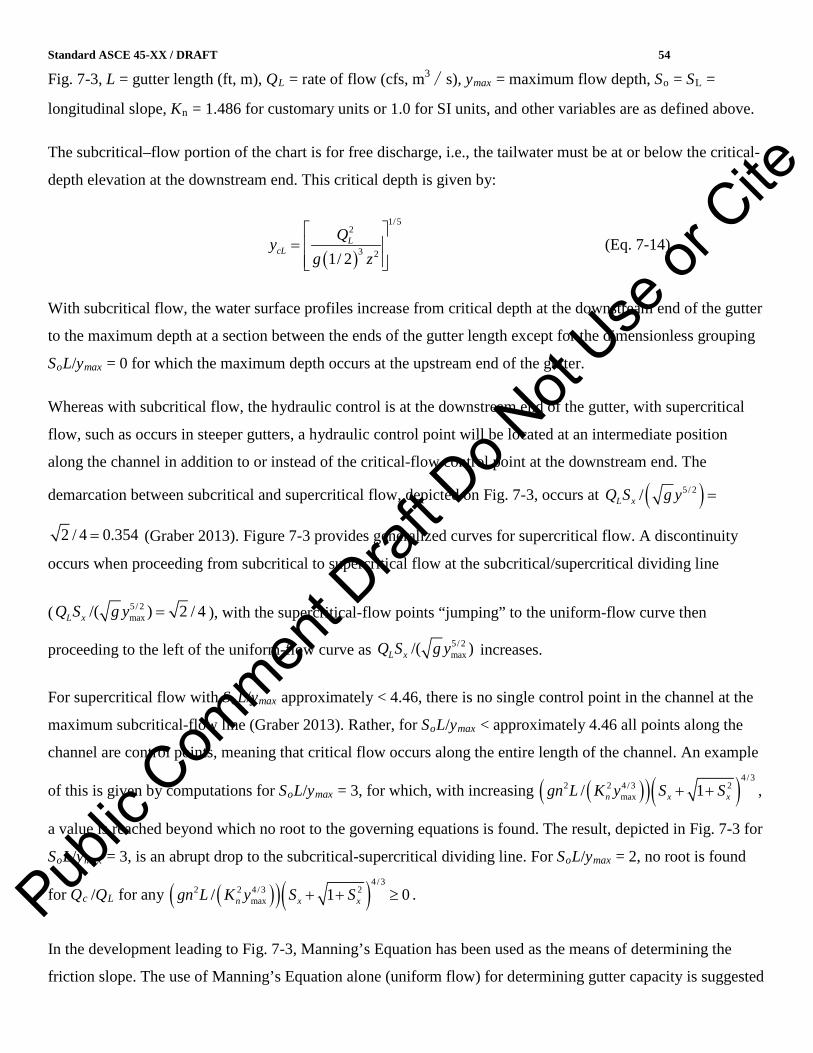
Standard ASCE 45-XX / DRAFT 54
Fig. 7-3, L = gutter length (ft, m), QL = rate of flow (cfs, m3∕s), ymax = maximum flow depth, So = SL =
longitudinal slope, Kn = 1.486 for customary units or 1.0 for SI units, and other variables are as defined above.
The subcritical–flow portion of the chart is for free discharge, i.e., the tailwater must be at or below the critical-
depth elevation at the downstream end. This critical depth is given by:
(Eq. 7-14)
With subcritical flow, the water surface profiles increase from critical depth at the downstream end of the gutter
to the maximum depth at a section between the ends of the gutter length except for the dimensionless grouping
SoL/ymax = 0 for which the maximum depth occurs at the upstream end of the gutter.
Whereas with subcritical flow, the hydraulic control is at the downstream end of the gutter, with supercritical
flow, such as occurs in steeper gutters, a hydraulic control point will be located at an intermediate position
along the channel in addition to or instead of the critical-flow control point at the downstream end. The
demarcation between subcritical and supercritical flow, depicted on Fig. 7-3, occurs at
(Graber 2013). Figure 7-3 provides generalized curves for supercritical flow. A discontinuity
occurs when proceeding from subcritical to supercritical flow at the subcritical/supercritical dividing line
( ), with the supercritical-flow points “jumping” to the uniform-flow curve then
proceeding to the left of the uniform-flow curve as increases.
For supercritical flow with SoL/ymax approximately < 4.46, there is no single control point in the channel at the
maximum subcritical-flow line (Graber 2013). Rather, for SoL/ymax < approximately 4.46 all points along the
channel are control points, meaning that critical flow occurs along the entire length of the channel. An example
of this is given by computations for SoL/ymax = 3, for which, with increasing ,
a value is reached beyond which no root to the governing equations is found. The result, depicted in Fig. 7-3 for
SoL/ymax = 3, is an abrupt drop to the subcritical-supercritical dividing line. For SoL/ymax = 2, no root is found
for Qc /QL for any .
In the development leading to Fig. 7-3, Manning’s Equation has been used as the means of determining the
friction slope. The use of Manning’s Equation alone (uniform flow) for determining gutter capacity is suggested
( )
1/52
3 21/ 2L
cLQy
g z
=
( )5/ 2/L xQ S g y =
2 / 4 0.354=
5/ 2max/( ) 2 / 4L xQ S g y =
5/ 2max/( )L xQ S g y
( )( )( )4/32 2 4/3 2
max/ 1n x xgn L K y S S+ +
( )( )( )4/32 2 4/3 2
max/ 1 0n x xgn L K y S S+ + ≥Public
Com
ment D
raft D
o Not
Use or
Cite

Standard ASCE 45-XX / DRAFT 55
in numerous publications, some of which have been cited by Graber (2013). Figure 7-4 has superimposed on
Fig. 7-3 curves for uniform-flow conditions, discussion of which, beyond that presented here, is given by
Graber (2013). Manning’s Equation alone does not always provide an adequate basis for estimating gutter
capacity. Figure 7-4 shows that the uniform-flow approximation is always conservative for subcritical flow with
SoL/ymax > 5 and FL = 1. For supercritical flow, Fig. 7-4 shows that at the higher values of SoL/ymax the curve
for spatially varied flow fairly closely parallels the Manning’s Equation-alone curve, indicating when
Manning’s Equation alone provides a more reasonable approximation. In those cases, the curves move closer as
decreases, becoming nearly convergent for SoL/ymax = 50. In no case is the Manning’s
Equation-alone curve conservative for supercritical flow. Figure 7-4 shows the conditions for which the
spatially varied flow chart values should be used.
For more complex systems, involving, for example, downstream submergence, a computer program may be
used for design and analysis purposes (see, e.g., Graber 2004).
Selection of the number, location, and size of inlets is based on the magnitude of the design flow. Curb inlets
are considered to be relatively inefficient. The following references provide additional design information for
curb inlet design: ASCE/WEF (1992), Urban Drainage and Flood Control District (Denver 2008a), Drainage of
Highway Pavements (FHWA 1984), and Urban Drainage Design Manual (FHWA 2001a).
Grate inlets are available in a variety of sizes and shapes. FHWA (2001) provides a procedure for merging
theory and experimental data to estimate the gutter flow intercepted by grate inlets, curb-opening inlets, slotted
inlets, and combination (curb opening and grate) inlets. The procedure assumes uniform flow using Manning’s
Equation. Figure 7-5 provides curves (solid lines) of intercepted flow Qi versus longitudinal slope and
approaching flow Q, for a particular type and size (width W and length L) of grate and cross slope, calculated
according to the FHWA procedure, which matches the curves given in a specific example (FHWA 2001, pp. B-
14–16). A more logical approach for subcritical flow is to assume critical-flow approach conditions, which are
the conditions expected at the entrance to an inlet provided that the inlet and conditions downstream of the inlet
creates a backwater depth not greater than the critical depth of the gutter flow just upstream of the inlet (likely
conditions with a reasonable design). As expected, the downstream critical depth of flow in the gutter is seen to
be less than the maximum depth in the gutter for subcritical flow from Fig. 7-3 by comparing
for conditions below the maximum subcritical-flow line to conditions at that line for the same QL and Sx giving
ymax ycL. By similar reasoning for the uniform-flow depth yunif , Fig. 7-3 shows for subcritical uniform-flow
conditions that yunif ycL, with implications discussed following.
5/ 2max/( )L xQ S g y
( )5/ 2max/L xQ S g y
≥
≥
Public
Com
ment D
raft D
o Not
Use or
Cite

Standard ASCE 45-XX / DRAFT 56
For supercritical flow, at the downstream end of the gutter , as can be seen from Fig. 7-3 and
reasoning given. Therefore, it is not adequate to use the uniform-flow depth for inlet design with supercritical
approach flow, impractical to use each ymax such as determined from Fig. 7-3, and conservative to use yc. The
latter is thus recommended, and the same procedure as described as follows for subcritical flow can be used for
supercritical flow.
The nine-step FHWA (2001) procedure may be modified for critical-flow approach conditions by changing
Steps 1 and 3 of the procedure. For Step 1, the top width for critical-flow conditions is calculated for a given
flow and cross slope by . For Step 3, the velocity approaching the inlet is calculated by
. Other steps then remain unchanged. The dashed lines of Fig. 7-5 are for critical-flow
conditions with values of Sx and Q corresponding to the uniform-flow curves. The dashed lines are independent
of longitudinal slope, because the critical-flow depth is independent of longitudinal slope. This independence
allows a more general figure, such as Fig. 7-6, to be prepared for a particular inlet. The range of Sx values on
Fig. 7-6 are those considered acceptable by FHWA (2001), which cites AASHTO policy. Whereas splash-over
(a portion of the flow bypassing the grate) occurs with the assumption of uniform flow to the right of the
maximum value of those curves, there is no splash-over for this grate under the more realistic critical-flow
conditions.
For flow continuing on beyond an inlet to the next inlet, Fig. 7-3 can be used again as it was for the flow to the
inlet just considered provided an equivalent gutter length is used. That equivalent length Le is given by
(Eq. 7-15)
in which Ln = distance to the next inlet from the inlet just considered, Qn = flow continuing to the next inlet
(equaling Q – Qi for the inlet just considered), and qn = uniform inflow per unit length over the distance to the
next inlet from the one just considered. The downstream critical depth can then be used for the inlet design. The
procedure can be repeated for successive gutter lengths and inlets.
Additional hydraulic capacity information may be available from manufacturers’ literature. For coupled
analyses of streets and stormwater conduits, grate capacity can be calculated from weir or orifice equations or
combinations of the two. See references in 7.6.
Typical inlet structure location and spacing guidelines are as follows:
maxunif cy y y< <
( ) 1/52 38 / xT Q gS =
( )22 / xV Q T S=
ne n
n
QL Lq
= +
Public
Com
ment D
raft D
o Not
Use or
Cite
Standard ASCE 45-XX / DRAFT 57
• At all sump locations and intersections of sufficient size and number to intercept all runoff;
frequently multiple inlets are required at sags to account for grate clogging
• Along roadway with a maximum spacing of 300 to 400 ft (90 to 120 m) to provide cleanout access
to the storm drain pipe
• At road superelevation transitions to prevent street cross drainage
• Immediately downstream from side drainage contribution (parking lots, etc.)
• Along street perimeter sufficient to keep street flow within design limitations; determine the
intercept capacity of each inlet remembering that the bypass flow affects the location of the next
downstream grate.
In many urban areas it is not uncommon to have gutter flow widths, or spreads, restricted to 8 ft (2.4 m) or less.
In cases where traditional grate inlets allow a substantial portion of the gutter flow to bypass, roadways may
require more of such inlets than what is economical. Line drains then may be desirable.
Line drains can be used to enhance the intercept capacity of the traditional inlets or can be used as a stand-alone
system. Because of their modular nature, the length of these drains can be designed to intercept the entire gutter
flow at each location, thus eliminating bypass flows. This would allow for increased spacing of these structures,
potentially making the design more economical.
In addition, line drains also can benefit the designer by
• Intercepting sheet flows prior to the depth of flow that promotes hydroplaning
• Eliminating flanking inlets required at sump locations while providing equal or greater inlet capacity
• Allowing for drainage without infringing on existing utilities [in many cases total required
excavation can be less than 0.5 m (1.5 ft)].
Information on the design and capacity of slotted rain and precast polymer concrete trench drain inlets can be
obtained from manufacturers’ literature; however, the basis for such information should be evaluated.
Inlet structure selection should accommodate traffic needs and safety considerations for vehicular traffic,
pedestrians, and bicyclists. Furthermore, if floating debris is expected to occur during storms, provisions should
be included in the design to minimize debris blockage at inlets. The inlets should be designed to deliver the
design runoff to the conveyance system safely. Public
Com
ment D
raft D
o Not
Use or
Cite

Standard ASCE 45-XX / DRAFT 58
7.3.2. Culverts
Culverts are relatively short conduits typically used for road crossings of small to moderate-sized streams.
Culverts are available in a variety of shapes and materials, some exceeding 20 ft (6.1 m) spans. Culverts can be
prefabricated or custom-made in the field. Culvert hydraulic analysis has been refined to several widely used
procedures because of the abundant use of this type of conduit.
Culverts cause an abrupt change in streamflow characteristics. The acceleration of flow that occurs causes head
losses. Flow within the culvert can range from tranquil to rapid, and the structure can flow either partially full or
under pressure. Hydraulic analysis of culverts requires consideration of tailwater conditions, friction losses
related to the culvert material and flow character, inlet and outlet losses, and form losses within the culvert
because of bends or other streamflow perturbations.
The design of culverts is simplified by the availability of laboratory research that has been completed by the
Federal Highway Administration (FHWA), and others. Chow (1959) gives six culvert flow classifications that
represent the range of hydraulic conditions that occur in culverts. As illustrated in Fig. 7-7, discharge equations
have been developed for each classification. In general, one or a combination of the following controls the
elevation of flow approaching a culvert:
• Critical depth control at inlet
• Tailwater depth control
• Culvert entrance or barrel geometry
Peak discharge through the culvert is estimated by application of the continuity equation and the energy
equation between the approach channel and a section within the culvert. When critical depth controls at the
culvert entrance, culvert capacity is a function of entrance configuration and the change in velocity head at the
entrance. Downstream culvert features, such as barrel friction and tailwater, do not affect the capacity for this
case.
The FHWA (1985) has developed culvert nomographs that provide a simplified culvert analysis procedure.
These curves include the numerous available culvert shapes and materials, and the various flow types that are
subdivided into inlet control (critical depth control at inlet) and outlet control (tailwater and friction loss
control). Following is a brief analysis procedure summary. Public
Com
ment D
raft D
o Not
Use or
Cite

Standard ASCE 45-XX / DRAFT 59
7.3.2.1. Opening Size Determination.
7.3.2.1.1. Flood Flow Determination.
1. Obtain flood flow/frequency relationship (i.e., mean annual, 10-year, 50-year, and 100-year
flood flows) at proposed structure site.
2. Flows should be checked by two methods when possible.
3. Discuss design flood criteria with owner.
4. Present hydrologic design criteria and risk to owner.
5. Check minimum required regulatory design criteria.
6. Always convey failure risk to owner regardless of minimum regulatory requirements. This
should be communicated in terms of percent chance of exceedance for given design.
7.3.2.1.2. Downstream Hydraulic Conditions.
Downstream tailwater should be computed with normal depth where applicable. If this is not applicable, start
calculations from a downstream hydraulic control (i.e., weir, or normal depth control) and perform backwater
analysis to estimate tailwater.
7.3.2.1.3. Culvert Hydraulic Design.
1. Utilize design charts (e.g., FHWA 1985) or computer programs with sound algorithms when
possible to minimize calculation error potential.
2. Always check both inlet and outlet control design charts for manual culvert calculations and
utilize the condition that produces the highest headwater.
3. Normal depth analysis is not sufficient for culvert design, except to characterize flow regime.
4. Analyze range of flows to design for flood conditions and to minimize sediment deposition
potential during base flows.
5. Perform separate calculations for multiple culverts with different characteristics.
6. Be aware that increased upstream flooding may not be allowed by governmental regulation
without special considerations.
7. Extend riprap sufficiently downstream until streamflow lines fill channel and velocities become
nonerosive. Culverts tend to accelerate flow velocity at outlet. Stone riprap or other outlet
protection should be designed to handle a range of velocities.
Public
Com
ment D
raft D
o Not
Use or
Cite

Standard ASCE 45-XX / DRAFT 60
8. Provide headwalls or extend riprap up embankment slopes upstream and downstream to protect
against erosion caused by eddy currents.
9. Pay close attention to inlet condition. For example, if the bell end of a round culvert faces
upstream, the inlet loss coefficient is 0.2. A square-edged round culvert has a loss coefficient of
0.5.
7.3.2.2. Special Considerations.
7.3.2.2.1. Flow Continuity.
It is estimated that there are hundreds of thousands of culverts blocking fish passage in the United States
(Stranahan 2009). Such passage is not only important to fish that migrate into fresh waters to breed
(anadromous) or from fresh waters to the ocean to breed (catadromous), but for nonmigratory species as well.
Connectivity criteria for the design of culverts to facilitate such movements are presented by Singler and Graber
(2005) the U.S. Department of Agriculture (2008), and the Federal Highway Administration (2010). Feurich,
Boubée, and Olsen (2011) is a useful reference in itself and for the additional references that it cites. In rare
cases, where a blockage across a stream protects an upstream vernal pool by blocking predatory fish, a culvert
added through such a blockage should be elevated (“perched”) to maintain the lack of connectivity.
7.3.2.2.2. Stone Riprap Outlet Design.
Accommodate a range of design velocities. A geocomposite or filter blanket may be required under the riprap as
discussed in 7.3.6.2.
7.3.2.2.3. Joint Design.
Be careful to select joints capable of withstanding design pressures. Any round concrete pipe subject to pressure
flow requires rubber gasket joints placed in pipe spigot groove. Joints with pressure exceeding 5 to 10 psi (70
kPa) require special design consideration. Under no circumstances should a pipe culvert be allowed to flow full
without special considerations for watertight joint design.
7.3.2.2.4. Utility Interference.
Always check for existing utilities at proposed structure location before beginning design work.
7.3.2.2.5. Standard Details.
Utilize time-tested and proven standard state highway department details when possible and available. Pub
lic C
ommen
t Draf
t Do N
ot Use
or C
ite

Standard ASCE 45-XX / DRAFT 61
7.3.2.2.6. Safety Considerations.
Always consider life safety features including guardrails, trash racks, warning signs, railings, and so on.
7.3.2.2.7. Freeboard.
Upstream design flood elevations should be contained at least 1 ft below top of road or berm elevations.
Calculate freeboard requirements for critical structures such as dams and levees to provide for wave action.
7.3.2.2.8. Flow over Top of Road.
Where possible, provide a contingency flow path over a portion of road that can handle overtopping when the
design flood is exceeded.
7.3.2.2. 9. Special Hydraulic Losses.
Accommodate the following losses into the hydraulic calculations:
• Bend losses
• Skew
• Flow convergence
• Unusual turbulent flow (macro-turbulence)
• Restrictions
• Expansion/contraction
Some losses must be approximated; apply conservative loss values in these cases.
Regulatory Requirements.
Culverts typically require construction approvals from the following agencies in the United States:
• Corps of Engineers (wetland and navigable waterway fill)
• State and local highway departments
• Municipal authority
• State environmental agencies
• Federal emergency management agency (streams with floodways)
ASCE/WEF (1992) includes a culvert analysis form that can be used to organize the analysis procedures. Table
7-3 provides a summary of culvert entrance loss coefficients. Additional references that provide entrance loss
Public
Com
ment D
raft D
o Not
Use or
Cite

Standard ASCE 45-XX / DRAFT 62
coefficients, Manning’s roughness coefficients, conduit characteristics, and culvert capacity nomographs
include Modern Sewer Design (AISI 1999), Handbook of Steel Drainage and Highway Construction Products
(NCSPA 2007), Concrete Pipe Design Manual (ACPA 2004), Portland Cement Association (1964), and the
Uni-Bel Handbook of PVC Pipe (2001).
Numerous computer models are available that automate the culvert or bridge design process or both including
• HEC-RAS (USACE 2010)
• HY-8 [Federal Highway Administration program for culvert analysis (FHWA 2013)]
• Proprietary culvert design programs
• FEQ [U.S. Geological Survey’s program for simulating unsteady flow in a channel network and
components (Franz and Melching 1997)]
7.3.3. Bridges.
It is seldom economical to bridge the entire floodplain at river crossings. Bridges are constructed to
accommodate road crossings of rivers while providing sufficient conveyance for the passage of floods. Bridges
cause a constriction to flood flow, particularly in the floodplain where bridge abutments and embankments
provide a blockage to natural streamflow. Streamflow lines are forced to converge through the bridge open area
causing a flow contraction upstream and an expansion downstream. Head losses because of expansion typically
cause the greatest hydraulic loss. Losses through the bridge structure also can be significant if the waterway
opening is small and the bridge dimension in the direction of streamflow is large. Bridges cause a localized
increase in flood levels upstream to overcome the head losses through the structure.
As illustrated in Fig. 7-8, three types of flow can occur with bridges. Type I flow is most commonly
encountered in urban bridge design and involves subcritical flow conditions through the bridge and upstream
and downstream of the bridge. The FHWA (1978) provides analysis procedures for this type of flow regime.
Backwater estimation of Type I bridges is obtained by applying the energy principle between stream cross
sections located upstream and downstream from the bridge. The locations of these cross sections are selected to
be sufficiently distant from the bridge faces to allow for full contraction and expansion of streamflow lines. A
common rule of thumb requires that expansion can occur at a maximum ratio of 1:4 (downstream
distance:lateral expansion distance) on each side of the stream. The streamflow line contraction ratio upstream
of a bridge is assumed to be 1:1.
Type II flow involves bridge structures with flow passing through critical depth within the bridge constriction.
Backwater is independent of downstream conditions for this scenario. FHWA (1978) has developed a
Public
Com
ment D
raft D
o Not
Use or
Cite

Standard ASCE 45-XX / DRAFT 63
backwater expression for Type II flow by equating the total energy between the upstream approach river cross
section and the point at which the water surface passes through the critical stage in the bridge constriction.
Type III flow represents structures where critical flow occurs upstream and downstream of the bridge
constriction, and also within the bridge. This unusual case can occur in mountainous regions; however, see
7.3.6.2 when assessing supercritical versus subcritical flow in steep streams. Backwater should not occur in
these cases due to the supercritical flow regime. The designer should, however, be aware of possible water
surface undulations that can occur in the vicinity of the restriction.
Backwater analysis through bridge structures should consider the following:
• Backwater coefficients through bridges vary, depending on bridge abutment length and shape at the
waterway opening.
• Bridge pier shape, orientation, and dimension have an effect on backwater.
• Bridge orientation skewed to the direction of normal streamflow will reduce the effective open area
of the bridge.
• Dual bridges of similar design may produce less than two times the head loss of a single bridge if the
bridges are located near one another.
• Flood discharges that inundate the bottom of bridge girders can produce orifice flow conditions.
Discharge coefficients are available for the case when only the upstream girder is submerged and for
when all girders are submerged (FHWA 1978).
• Flow over roadways should be evaluated when flood elevations exceed the minimum top of road
elevation. Further details are available in FHWA (1978).
• Bridge scour associated with eddies and increased local velocities should be considered. A
comprehensive review of bridge scour prediction, modeling, and countermeasures is given by Deng
and Cai (2010).
The geometric, upstream, or downstream conditions assumed by the methods discussed are limited and not
always applicable. In such cases, solutions can be obtained using continuity, energy, and momentum principles.
Such solutions have been published for riverine reaches upstream and downstream of the bridge [e.g., Ippen
(1950) and Graber (1982)]. Solutions when there are ponds immediately upstream and downstream of the
bridge are discussed by Graber (1999). Public
Com
ment D
raft D
o Not
Use or
Cite

Standard ASCE 45-XX / DRAFT 64
Although bridges are commonly better than culverts at providing connectivity to facilitate the movement of
fishes, it is important to attend to their proper design for this purpose as well. References providing design
guidance for connectivity are given in 7.3.2.2.1.
7.3.4. Spillways and Drop Structures.
Spillways are used in urban areas to control the level of recreational and water supply lakes and detention/
retention and sedimentation ponds. They also are used as hydraulic drop structures to provide a flow transition.
Spillways generally are hydraulic controls that produce critical depth. These structures can include
• Broad and sharp crested weirs
• Ogee spillways
• Straight drop spillways
• Chute spillways
• Conduit and tunnel spillway
• Side channel spillways
• Baffle apron drop spillways
• Culvert spillways
• Siphon spillways
Furthermore, spillways can include gates for flow control or can be ungated with corresponding uncontrolled
overflows. Gated spillways include flashboards and stoplogs, rectangular lift gates, or radial gates. Spillway
type selection depends on many factors including economics, desired upstream elevation and storage
characteristics, extent of vertical drop, magnitude of design flow, downstream transition characteristics, and
degree of required flow regulation, if any.
Flow over weirs and ogee shaped spillways can be characterized generally by the following expression:
(Eq. 7-16)
where
L = width of the spillway perpendicular to the streamflow lines
H = total head on the weir crest including the velocity of approach head
( )Q CL H= 3 2/
Public
Com
ment D
raft D
o Not
Use or
Cite

Standard ASCE 45-XX / DRAFT 65
C = variable coefficient of discharge.
The value C changes with the depth of the weir and flow and the type of weir. Furthermore, the discharge over a
spillway is reduced as tailwater rises above critical depth on the crest, thereby submerging the weir flow.
Additional considerations in weir hydraulics include pier and abutment effects, which can reduce the effective
weir length, variable water surface profile and streamflow line transitions for side channel weir configurations,
and approach channel characteristics. If a gate is included on top of the spillway crest, the hydraulic principles
of orifice flow will apply.
The following references provide further discussion regarding spillway analysis procedures and loss and
discharge coefficients: U.S. Department of the Interior Bureau of Reclamation, Design of Small Dams (1977a);
Brater and King, Handbook of Hydraulics (1976); and U.S. Department of the Army, Army Corps of Engineers,
Hydraulic Design of Spillways (1965).
Hydraulics of conduit, culvert, and tunnel spillways generally follow the principles outlined in 7.1 and 7.2.2.
Chute, side channel, baffle apron drop, siphon, and straight drop spillways each have unique hydraulic
characteristics. Further discussion on design procedures for these type structures can be found in the following
reference: U.S. Department of the Interior Bureau of Reclamation, Design of Small Canal Structures (1978).
7.3.5. Energy Dissipation and Outlet Structures.
Hydraulic structures generally involve the focusing of stormwater flow through an artificially made structure.
The relatively rapid flow characteristics at the outlet from these structures should be managed and dissipated.
The streamflow lines should transition properly back to the natural nonerosive streamflow character
downstream of these structures. Numerous energy dissipation devices are available to accomplish this
transition. Following is a summary of several commonly used structures.
7.3.5.1. Straight Drop Spillways.
Drop structures can be employed to dissipate energy in steep channel areas. Where long-term performance and
stability are required, drop structures built using poured-in-place concrete construction or prefabricated
aluminum plate components usually are employed. Drop structures generally are constructed of concrete.
Following are two references that provide additional information on drop structure geometry: Chow (1959) and
U.S. Department of the Interior Bureau of Reclamation (1978).
7.3.5.2. Flip or Roller Bucket Spillways
Slotted or solid flip or roller bucket spillways can often be employed for energy dissipation. These structures are
located at the downstream terminus of overflow spillways. They typically are used in stream channels that have
Public
Com
ment D
raft D
o Not
Use or
Cite

Standard ASCE 45-XX / DRAFT 66
competent bottom materials such as bedrock. These devices are also used when the tailwater depth is too great
for the formation of a hydraulic jump. This type of dissipater forms two streamflow line rollers. One on the
surface moves counterclockwise and is contained within the region above the curved bucket. The other is
considered a ground flow roller moving in a clockwise direction and is located downstream from the bucket.
The roller movements intermingling with incoming flows effectively dissipate energy and prevent excessive
downstream scouring.
7.3.5.3. Impact Stilling Basin
Impact stilling basins can be used at the terminus of open chutes or closed conduits with flows up to 400 cfs (11
m3/s). Approach flow velocities should be less than 50 ft /s (15 m/s). A riprap-lined outlet channel is required
downstream of the impact basin. Sufficient freeboard should be provided to contain macro-turbulence and
splashing that routinely occur at these structures.
7.3.5.4 Hydraulic Jump Stilling Basins
These stilling basins can be designed with a range of energy dissipation features to accommodate variable flow
conditions. Hydraulic jump formation is possible and can accommodate greater flow than impact stilling basins.
These stilling basins can be as simple as a depressed rectangular box at the end of a chute or can include
features, such as dentated end sills, chute blocks, and riprap outlet channels. The U.S. Bureau of Reclamation
(Peterka 1964) has developed nine types of hydraulic jump stilling basins, four of which are summarized as
follows. Also see U.S. Department of the Interior Bureau of Reclamation (1978):
Type I. Applicable for Froude numbers less than 2.5. The key design parameter involves the basin length.
For Froude numbers less than 1.7, no special stilling structure is necessary.
Type II. This structure type is applicable when approach velocities exceed 50 ft/s (15m/s) and for Froude
numbers that exceed 4.5.
Type III. This structure type is applicable when approach velocities are less than 50 ft/ s (15m/s) and when
the Froude number exceeds 4.5. This structure is similar to the St. Anthony Falls stilling basin
(Chow 1959, 415−417).
Type IV. This type structure is applicable for Froude numbers between 2.5 and 4.5.
Vertical sidewalls are preferred over sloped walls for stilling basin structures. Vertical sidewalls promote stable
flow and are more likely to contain hydraulic jump macro-turbulence. Public
Com
ment D
raft D
o Not
Use or
Cite

Standard ASCE 45-XX / DRAFT 67
7.3.5.5. Baffled Chute Spillway
This type structure is capable of handling up to 60 cfs/ ft (1.8 m3/s /m) of apron width. This structure is an
efficient energy dissipation structure in terms of length of outlet system required to dissipate energy. A riprap
outlet channel is required for this structure.
7.3.5.6. Energy Dissipating Headwalls
Various types of energy-dissipating headwalls are available for culvert outlet structures. These headwalls
include concrete aprons with concrete roughness elements or impact blocks. Refer to ASCE/WEF (1992) for
further information on this type of structure.
Because of the complexity and variability of hydraulics associated with each of the energy dissipation and outlet
structures as discussed, the references mentioned should be consulted when designing these structures.
7.3.6. Open-Channel Linings
Drainage channels must be designed to maintain their function and geometric stability by withstanding erosive
forces. Following is a summary of several commonly used methods.
7.3.6.1. Vegetated Channels
Linings for flow channels are required mostly to maintain the design flow capacity for extended periods of time
while requiring minimum maintenance. Although many lining materials meet these basic needs, the most cost-
effective—when erosive and climatic conditions allow—has proven to be natural vegetation in the form of
grasses, legumes, and other low-growing groundcover vegetation. The use of vegetation, as an alternative to
other construction materials, is, of course, not recommended for those climates not suitable for vegetation
development and long-term support in the absence of artificial irrigation.
The advantage of natural vegetation as a channel lining is that it functions as part of the soil system. The root
structures of vegetative growth, when properly established, strengthen the root zone of the upper soil layers. In
turn, the top soil layers have significantly improved resistance to shear stresses resulting from the tractive forces
generated by runoff or channel flow. Natural vegetation alone, when fully matured and completely developed,
has been shown to withstand flow velocities up to 20 ft/s (6 m/sec) for short duration (1 h or less). Above this, a
“hard armor” lining generally is recommended.
One concern with establishing natural vegetation is that, unless sod is applied, the initial time has varying
degrees of coverage and subsequent protection. It is important to provide temporary coverage until new
Public
Com
ment D
raft D
o Not
Use or
Cite
Standard ASCE 45-XX / DRAFT 68
vegetation is reasonably well established. Toward this end, a number of products and techniques are available,
and the use of each depends on-site conditions and cost efficiency. The more common revegetation aids are
1. Covering the preseeded surface with chopped straw and plastic netting, with the netting applied over the
straw and secured to the soil; generally suitable for minor applications where service conditions are very
light
2. Covering the preseeded surface with a hydraulically applied mixture of organic materials and a binder to
form a nonstructural barrier layer over the soil surface; alternately, seed can be included in the mulch
mixture; generally suitable for less severe applications
3. Covering the preseeded surface with either of a variety of roll-out blankets or mats, which are secured to the
soil with stakes or pins; these products, depending on composition, either can provide temporary protection
(on which the product decomposes and may provide a mulching benefit) or offer permanent reinforcement
to the root zone
4. Covering the prepared surface with a geotextile and then applying a hydraulically applied mixture of
organic materials and a binder containing seed; as an alternative, the geotextile material can be penetrated
for planting of seedlings
5. Applying sod to the surface; until the new sod establishes a root structure with the site soil and “knits”
together, it will have less shear strength resistance and will require staking to prevent movement and
potential washout.
The effectiveness of vegetative covers for preventing or minimizing erosion depends on many variables and, as
a result, is very difficult to provide universally applicable specific data. Site conditions and service environment
factors require that the designer rely on local information and experiences, much of which are available from
regional sources, such as the U.S. Natural Resources Conservation Service (NRCS). However, the basic
mechanics of erosion involve impact forces from rainfall, the effects of wind on bare or sparsely vegetated soils,
runoff velocities and quantities, depth and duration of flow, and soil-erodability factors.
The effects of rainfall impact and wind generally are not major concerns with mature vegetation coverage.
However, these are major problems during the revegetation period, and the mat, blanket, and protective
mulching techniques are especially useful at this time.
The other factors related to soil characteristics and flow dynamics affect the in-service stability of the lining.
Basically, these must resist shear forces that can dislodge the lining material. The effectiveness of the lining
system, if vegetative, can be significantly variable as a function of the type of soil and plant material selected.
Some plant materials offer superior durability and can develop stronger root structures, making them more
Public
Com
ment D
raft D
o Not
Use or
Cite

Standard ASCE 45-XX / DRAFT 69
desirable for this application. The availability of these depends on regional conditions. There are also geotextile
products that act as channel liners while accommodating the establishment of vegetation through holes or cells
built into the manufactured components.
When service conditions involve high-flow velocities, widely fluctuating flow conditions, long flow duration, or
large unit quantities of flowing water, vegetative cover may not be adequate, in which case other methods
discussed as follows would be more suitable.
7.3.6.2. Lined Channels
When flow velocities exceed the capacity of the natural channel bottom soils and vegetation, a channel lining
should be provided. Channel lining can consist of the following (also see 7.3.6.3):
• Concrete-filled fabric mats
• Rock riprap
• Precast concrete erosion revetments
• Cabled and interlocking block revetments
• Soil cement
• Bagged concrete
• Gabions
• Soil bioengineered bank protection
ASCE/WEF (1992) provides additional information on design criteria and procedures for channel erosion
protection measures. The utilization of flexible liner protection materials, such as riprap and gabions, generally
is limited to subcritical flow conditions, supercritical flow conditions with Froude numbers generally less than
1.7, and streamflow velocities that do not exceed the practical limitations of these materials to withstand the
associated tractive forces. Flexible linings are not recommended in flow situations where hydraulic jumps are
possible.
“Hard armor,” consisting of select stone or other materials, may be more suitable. In these conditions, the stone
may require separation from the site soil by either a filter blanket of graded sand or gravel or a site-suitable
geocomposite in order to prevent loss of soil particles and subsiding of the armor. The filter blanket or
geocomposite must be of such type to minimize blinding or clogging from soil fines to prevent the development
of hydrostatic groundwater forces beneath the structure. Determination of the need for a filter blanket and
design methods are given in the Bureau of Public Roads, Use of Riprap for Bank Protection (FHWA 1961b).
Public
Com
ment D
raft D
o Not
Use or
Cite

Standard ASCE 45-XX / DRAFT 70
The need for and design of geotextile separators are discussed by Koerner (2005, Section 9.1). Geosynthetic
(e.g., expanding geocells) or recycled plastic products also are available, which can be used as a replacement for
riprap.
Channels lined with riprap or gabions also are used at roadsides and other stormwater drainage applications and
also as lateral collector channels at the top of slopes, such as at landfills, connected to multiple riprap or gabion-
lined channels continuing down the slope to a collector channel at the foot of the slope. For channels on shallow
slopes, Manning’s n values of 0.020−0.035 generally apply. However, for steep channels, careful consideration
is necessary in the selection of Manning’s n values, design for channel stability, and awareness of the possibility
of roll waves and cross waves. On steep slopes with shallow flow, substantially larger n values than those
corresponding to channel depictions in, for example, Chow (1959) will apply. Charts given in Design of
Roadside Channels with Flexible Linings (FHWA 2005) are given for slopes up to 25%. However those charts
or the formulas given for use with the associated iterative procedure are based on experimental work for a
maximum slope of 8%. At larger slopes, the iterative procedure may not converge. When convergence is
obtained, the procedure will enable determination of flow depth and channel stability. This procedure, based on
Bathurst et al. (1981), will commonly reveal a subcritical flow and flow depth higher (with implications for
channel stability) than with supercritical flow that would occur at lower n values. The same effect on flow
regime was noted by Trieste (1992, 1994). For slopes beyond the range of FHWA (2005) and Bathurst et al.
(1981), n values as a function of slope, hydraulic radius or hydraulic depth, and riprap size can be obtained from
other references; a good review is given by Bettes (1999); with the flow depth thus determined, the stability
design method in FHWA continues to apply. For n values, a more recent comprehensive review, new
developments, and recommendations (applicable to artificially made triangular, parabolic, and trapezoidal
cross-sections) are given by Froehlich (2012).
When supercritical flow does occur, cross waves occurring at channel bends may cause overtopping of the
channel and should be considered, see, e.g., Ippen (1950) or Chow (1959). Roll-wave instability should be
either avoided [Vedernikov number < 1 (Chow, 1959)] or resulting wave heights be considered, where suitable
predictive information exists, for example, wide rectangular channels with Froude numbers less than 2 (Brock
1970), to avoid overtopping.
7.3.6.3 Mortared Masonry, Poured Concrete and Metal or Plastic Prefabricated Channels
The Roman aqueducts are early examples of open channel structures. Generally of mortared masonry
construction, they transported water over large distances using gravitational forces and are seen today as
overhead structures.
Public
Com
ment D
raft D
o Not
Use or
Cite

Standard ASCE 45-XX / DRAFT 71
A typical modern open channel structure consists of poured concrete bottom and side elements, although other
materials may be applicable. Concrete has demonstrated its long-term durability, cost efficiency, and low
maintenance benefits for channel construction and is commonly the optimum construction for large-scale
channels.
Light gauge metal (steel and aluminum) prefabricated channel structures have been in use for many years,
serving remote areas or for temporary installations. For small channels, interlocking plastic liners are available
as well.
Impervious open channels, although serving in capacity as a lining material, will have more structural
requirements than vegetative-protected open soil channels. The issue of shear stresses resulting from tractive
forces created by flowing water is a main concern. These forces not only create tensile forces within the
structure (essentially along its longitudinal axis), but also result in shear forces at the lining-soil interface. Thus,
the structural components of the channel material must be capable of controlling these forces to resist tensile
failure of the structure and displacement along the soil–structure interface. Additional considerations include,
but should not be limited to, the added forces created by changes in flow direction because of bends in the
channel, macro-turbulence created by high velocities, the potential for scour (especially related to debris in
runoff ), and stresses resulting from temperature deviations.
7.3.7. Pumps
Pumps are used in urban stormwater drainage systems when gravity flow is not possible. Furthermore, the
utilization of pump systems for stormwater drainage usually is associated with stormwater storage facilities that
attenuate flood peaks and reduce peak pump operating characteristics. Because of the operating expenses and
maintenance required by pump systems, they should be avoided when possible.
Pump selection and pump station configuration generally are selected depending on peak flow requirements, the
duration of pump operation time, service area drainage requirements, and the required vertical lift. Stormwater
pumps are typically large, working against relatively low heads. Pump types can include the following [for
additional information on pump selection, refer to U.S. Department of Transportation’s Manual for Highway
Stormwater Pumping Stations “FHWA (1982)” and Highway Stormwater Pump Station Design “FHWA
(2001b)”]:
7.3.7.1. Vertical Pumps.
Vertical pumps are either single-stage propeller pumps for low heads or mixed flow pumps for higher heads.
Two-stage propeller pumps can be obtained to double the pump capacity.
Public
Com
ment D
raft D
o Not
Use or
Cite

Standard ASCE 45-XX / DRAFT 72
7.3.7.2. Submersible Pumps.
This type pump combines the wet and dry wells, thereby simplifying pump station design.
7.3.7.3. Centrifugal Pumps.
This pump type requires dry pit pump station construction.
7.3.7.4. Screw Pumps.
This nonpressurized pump system is frequently used in agricultural areas.
7.3.7.5. Volute or Angle Flow Pumps.
Typically the motor is located above the pump room operating floor and the pump mechanism can be as much
as 25 ft (7.6 m) below. Vertically mounted volute or angle flow pumps usually are not utilized for stormwater
pumping because of pump complexity.
7.3.7.6. Discharge Conduits.
Conduits used for the discharge of stormwater from pump stations typically are pressurized systems. The
designer should pay appropriate attention to the design of pressure type joints and conduit access for the
pressurized portion of the system. Transient pressures should be considered in pump design. Slow opening and
closing valves is one method.
7.3.7.7. Stormwater Pumping Station Design.
7.3.7.7.1 Introduction
Consideration is given first to small to medium-sized pumping stations, defined by WEF (1993) as those for
which a single pump provides design capacity (with one or more others for low flows, alternating sequences,
and/or backup); such stations are of less than 200 l/s (3,200 gpm) capacity (WEF 1993). Larger submersible
pumps have become available (ASCE/WEF 1992), which allows larger stormwater pump stations to rely on a
single submersible pump. One can use a generalized solution for the hydrologic and hydraulic design of such
small to medium-sized stormwater pumping stations (Graber 2010). The benefits of the solution include (1) the
ability to consider the effects of storm duration rather than the fixed hydrology assumed in other methods, (2) a
simpler and more intuitive design procedure than other available methods, and (3) enabling the calculation of
storage requirements independent of the geometry of the wet well and any inundated upstream area.
The solution can be derived by first specializing four basic relationships on which a generalized solution for
detention basin design are based (Graber 2009a). The first is conservation of mass, relating the terms I =
Public
Com
ment D
raft D
o Not
Use or
Cite

Standard ASCE 45-XX / DRAFT 73
volumetric inflow rate, Q = volumetric outflow rate, and dS/dt = time rate of increase of effective storage
volume. Second is the inflow relationship, which is assumed to have the form of the trapezoidal inflow
hydrograph depicted on Fig. 7-9 with peak inflow Ip, linear rising limb to the time of concentration tc, duration
tr , and linear receding limb of duration Rtc ; additional terms on Fig. 7-9 are defined as follows. The third and
fourth relationships are simplified forms of the storage and outflow terms, expressed, respectively, as
S NH= (Eq. 7-17) mQ MH= (Eq. 7-18)
in which H is elevation measured upward from the elevation at which effective storage and outflow begin, and
N, M, l, and m are coefficients and exponents defined by Eq. 7.17 and Eq. 7.18.
Equation 7-17 is presented only for comparison with related formulations (Graber 2009a; 2009b); for present
purposes no restrictive assumption is made at this stage regarding the nature of S. Equation 7-18 is specialized
for the case of constant pumped outflow (when the pump is on) so that m = 0, Hm = 1, and Q = M. Constant
pumped outflow is a useful preliminary design assumption, also made by others (e.g., Burton 1980;
Baumgardner 1983; ASCE/WEF 1992; FHWA 1982, 2001; Froehlich 1994). The constant pumped flow is
assumed to start at ts = the time of intersection of M with the rising limb of the hydrograph, as also assumed by
Burton (1980) and depicted in Fig. 7-9.
7.3.7.7.2 Generalized Solution
The nondimensionalized time of pump starting is given by (Graber 2010):
s
c p
t Mt I= (Eq. 7-19)
The maximum outflow (constant M) and concurrent maximum storage volume denoted by S* (depicted by the
cross-hatched area between the inflow hydrograph and constant pumped flow on Fig. 7-9), occur at time
denoted by t*; nondimensionalized t* and S* are given by (Graber 2010):
* 1r
c c p
t t MRt t I
= + −
(Eq. 7-20)
( )* 1 11 1 12 2
r
p c c p p p
S t M M MR R RI t t I I I
= − + − − − + (Eq. 7-21)
The nondimensional inflow volumes are given by (Graber 2010):
Public
Com
ment D
raft D
o Not
Use or
Cite

Standard ASCE 45-XX / DRAFT 74
( )
2
2
1 , 2
(Eq. 7.22a)1 , (Eq. 7.22b)2
(Eq. 7.22c)1 1- ,
2 2
cc
c rp c c
rr r c
c c c
t t tt
V t t t tI t t
t t t t t t Rtt R t t
≤ = − < ≤ − − < ≤ +
The total inflow volume Vi is given by Eq. 7-22c for ( )r ct t Rt= + :
1 12
i r
p c c
V R tI t t
+= + − (Eq. 7-23)
The ratio of maximum storage volume to total inflow volume is obtained from Eq. 7.21 and Eq. 7.23:
( )1 11 1 1
2 2*1 1
2
r
c p p p
i r
c
t M M MR R Rt I I IS
V R tt
− + − − − + = +
+ −
(Eq. 7-24)
The following ratio of S*/Vi for /r ct t →∞ is obtained by taking the limit of Eq. 7-24:
/
*lim 1r ct t
i p
S MV I→∞
= −
(Eq. 7-25)
Equations 7.24 and 7.25 are plotted on Fig. 7-10 for R = 1.67; the selection of this R value is explained in
Graber (2009a). The values of S*/Vi are equal (independent of /r ct t ) at ( ) ( )/ 1 / 2pM I R R= + + at which
* / 1/( 2)iS V R= + ; the numerical values for R = 1.67 are M/Ip = 0.728 and S*/Vi = 0.272.
7.3.7.7.3 Comparison to Other Methods
Also plotted in Fig 7-10 is the relationship for estimating the required storage given in ASCE/WEF (1992)
[although attributed therein to the Federal Highway Administration (FHWA 1982), the method does not appear
in that publication]. That relationship is based on fitting a triangular hydrograph to the peak-flow portion of an
SCS (1986) [Soil Conservation Service, now National Resource Conservation Service (NRCS)] type inflow
Public
Com
ment D
raft D
o Not
Use or
Cite

Standard ASCE 45-XX / DRAFT 75
hydrograph, and deriving an equation given, in terms of present notation, by 2* / (1 / )i pS V M I= − . The
triangular hydrograph corresponds in Fig. 7-10 to / 1r ct t = ; the approximation can be seen to follow the curve
for / 1r ct t = up to / 0.15pM I ≅ and to significantly under predict the required storage for larger values of
/ pM I [if the upper curves are plotted for R = 1, their distance above the ASCE/WEF (1992) curve becomes
even greater]. Even for / 1r ct t = and R = 1 as assumed in the ASCE/WEF (1992) method, Eq. 7-24 does not
reduce to the ASCE/WEF equation; the method fails to consider what Baumgardner (1983) refers to as “storage
below pump-on elevation” and which, for the case considered here, is the storage associated with the area to the
left of tc (see Fig. 7-9), which becomes more significant as / pM I becomes larger. This is further addressed in
an example presented as follows.
FHWA (2001) properly cautions against using long-duration events, such as SCS/NRCS 24-hour hyetographs:
“Shorter duration storms that compare with the estimated time of concentration for the drainage area are usually
more appropriate for pump station design.” A method that accomplishes that end and is related to the method
discussed in the previous paragraph is given in ASCE/WEF (1992). It entails a triangular approximation to the
maximum intensity portion of the SCS/NRCS hyetograph. A comparative example of that method also is given
following.
Comparison with other methods, including Burton (1980) and Froehlich (1994) is given in Graber (2010, 2011).
7.3.7.7.4 Pump Operation
From Fig. 7-9 and Eq. 7-19, the pump start volume is given by
( ) ( ) 2, 1/ 2 1/ 2 /p start s c pV t M M t I= = (Eq. 7-26)
The start volume is measured upward from the dead-storage elevation in the wet well, which may be generally
taken to be equal to the pump-stop elevation. Water below that elevation must be assumed to remain in the wet
well. The dead-storage elevation can be based on the minimum required submergence of submersible pumps or
the minimum acceptable submergence of bell inlets. Avoidance of air-core vortices is one important
consideration in this regard. For submersible pumps, the minimum submergence also is based on cooling
requirements. Some submersible pumps have a cooling jacket with a glycol coolant that allows the pump to
operate without the motor being submerged; in such cases, the minimum submergence may be at the elevation
of the top of the volute (the manufacturer should always be consulted). For bell inlets and other configurations,
minimum submergence guidance is provided by ANSI/HI (1998).
Public
Com
ment D
raft D
o Not
Use or
Cite
Standard ASCE 45-XX / DRAFT 76
Referring to Fig. 7-9, the pump will continue to run until the time that maximum storage has been reached.
Beyond that time, the pump will continue to run until the difference between the cumulative inflow volume and
the cumulative pump discharge volume equals zero. Referring again to Fig. 7-9, generally this will occur
sometime after r ct t Rt= + . The cumulative inflow volume based on Fig. 7-9 has reached a maximum and
remains unchanged for r ct t Rt> + , and is given by Eq. 7-23.
Denoting the cumulative pump discharge volume by pV , the nondimensional cumulative pump discharge
volume is given by
p s
p c p c c
V M t tI t I t t
= −
(Eq. 7-27)
Setting i pV V= using Eq. 7.23 and Eq. 7.27, and solving for / ct t , gives the pump stop time, denoted by et , as
follows:
/ / 2 1/ 2/
e r c
c p p
t M t t Rt I M I
+ −= + (Eq. 7-28)
7.3.7.7.5 Example
A drainage area containing homes, appurtenant structures, and pervious surfaces is protected from external
flooding by a berm. However, runoff from the drainage area itself requires a permanent solution to address
flooding within the area behind the berm during times when the external water level is too high to permit one-
way gravity discharge through the berm. At a time of concentration of 6 min., the peak design (50-year) rate of
runoff using the SCS Graphical Peak Discharge Method (SCS 1986) is 0.182 m3/s (6.43 cfs). An essentially
identical value of peak runoff (within 1% in this case) alternatively can be obtained by converting the curve
number (CN) value to a rational method runoff coefficient (Graber 1992) and using the rational method. Table
7-4 gives values of rt , /r ct t , and rainfall intensity i. The latter are based on published rainfall data for Topsfield,
Massachusetts (Graber 1992), with linear interpolation for intermediate values of i. Successively larger storm
durations are considered; the peak rate of runoff decreases in proportion to the decrease in rainfall intensity as
the storm duration increases (Graber 2009a, 2009b). Values of ( )/i p cV I t are calculated using Eq. 7-23; values
of iV also are given, which shows their increase with increasing tr.
Different values of M are then considered, with the remaining columns of Table 7-4 based on one such value.
For each value of / pM I , values of * / ct t and * / iS V are calculated using Eq. 7.20 and Eq. 7.24, respectively.
Public
Com
ment D
raft D
o Not
Use or
Cite
Standard ASCE 45-XX / DRAFT 77
The values of ( )* / p cS I t are calculated from ( ) ( )( )* / /i i p cS V V I t . Equation 7-21 could be used alternatively.
Values of S* then are calculated from ( )( )* /p c p cI t S I t . The procedure is repeated easily for other values of M
in the same spreadsheet (not shown). The maximum values of S* all correspond to values of / pM I , /r ct t , and
* / iS V that comport with Fig. 7-10; that figure could be used instead of Table 7-4 to estimate values of * / iS V
giving maximum S*. It should be understood that values in Table 7-4 of * / ct t , * / iS V , ( )* / p cS I t , and S* for
other than the maximum S* are only trial values with no physical significance.
Figure 7-11 plots the maximum storage volume versus constant pumped outflow. On the basis of economic and
space considerations, the 0.0849 m3/s (3.00 cfs) pump capacity and corresponding 44.6 m3 (1,580 ft3) storage
capacity were selected. Pertinent values of the selected design in relation to Fig. 7-9 are M = 0.0849 m3/s (3.00
cfs), Ip = 0.138 m3/s (4.87 cfs), M/Ip = 0.0849/0.138 = 0.616, ts = 0.616(6) = 3.70 min. (Eq. 7-19), tc = 6 min., tr
= 14 min., t* = 14 + 1.67(6)(1 – 0.616) = 17.8 min. (Eq. 7-20), tr + Rtc = 14 +1.67(6) = 24 min., and te =
0.616(6) + (14/6 + 1.67/2 – ½)(6/0.616) = 29.7 min. (Eq. 7-28). Figure 7-12 plots the mass curves: cumulative
inflow volume based on Eqs. 7-22 and 7-23, and cumulative discharge volume based on Eq. 7-27. The
maximum difference between the two curves equals the 44.6 m3 (1,580 ft3) storage capacity, and the two curves
can be seen to intersect at te where the pump stop volume is zero.
The pump start volume of 9.43 m3 (333 ft3) (Eq. 7-26), maximum storage volume of 44.6 m3 (1,580 ft3), and
pump stop volume of zero are relative to a datum that is the minimum submergence. The minimum
submergence for the selected submersible, glycol-cooled, pumps is 33 cm = 0.33 m (13 in. = 1.083 ft). The
selected underground storage chamber has vertical sides and interior plan dimensions of 2.74 m (9.0 ft) x 4.88
m (16.0 ft) = 13.4 m2 (144 sq ft), for which the corresponding depths from the bottom of the chamber are 0.33
m (1.083 ft) stop, 0.33 + 9.43/13.4 = 1.03 m (3.39 ft) start, 0.33 + 44.6/13.4 = 3.66 m (12.0 ft) maximum. These
start and stop wet-well water elevations are specified in the design.
To check pump cycling during more frequent storms with lower inflows, advantage can be taken of the
demonstration by Pincince (1970) that the minimum cycle time for a single pump occurs when the inflow is
one-half of the discharge; that leads to the following equation for minimum cycle time tmin:
'min
4 ssVtM
= (Eq. 7-29) Public
Com
ment D
raft D
o Not
Use or
Cite

Standard ASCE 45-XX / DRAFT 78
in which 'ssV is volume of the wet well between pump start and stop and M is pump discharge used as already
stated, in this case, 'ssV = 13.4(1.03 – 0.33) = 9.38 m3, giving mint = 4(9.38)/(0.0849(60)) = 7.4 min., or 60/7.4 =
8 starts/h. This is acceptable for the selected pumps, which are rated for 15 starts/h.
An additional benefit of the generalized solution given above is that no assumption is made in deriving the
generalized solution regarding the wet-well geometry; that assumption did not come in until the chamber
geometry was selected in this example. In the case considered in this example, it was desired to know the extent
of flooding upstream of the pumping station associated with a 100-year rainstorm. An inlet grate was set at an
elevation corresponding to the maximum 50-year chamber water elevation. The same process as demonstrated
above for the 50-year storm was used to determine a 100-year storm S* = 52.4 m3 (1,850 ft3). The difference of
52.4 – 44.6 = 7.8 m3 (275 ft3) can be stored on the site without causing damage.
Graber (2010) compares the results of this example to the two ASCE/WEF (1992) methods mentioned, which
reveals that those methods would result in upstream flooding under the design storm conditions (in this case, the
50-year storm of critical duration).
The example given above also was run using HydroCAD® version 9.00’s modified rational method, dynamic
storage-indication method, and pump modeling features. The input matched that used for the aforementioned
example, except that constant pump discharge was replaced with a pump discharge-TDH (Total Dynamic Head)
relationship having miniscule increases in discharge as the TDH decreases (a necessary workaround). The
resulting HydroCAD output values were within 1% of those in the example.
The example given was run again with one change: an actual pump curve and discharge characteristics were
used rather than the 0.0849 m3/s (3.00 cfs) constant-flow assumption utilized above. That included a pump
discharge-TDH relationship for the selected pump and discharge information, which, coupled with wet-well
depth variations that affect the static head, enable calculation of the system flow-head relationship. HydroCAD
results showed a pump discharge varying from 0.0813 m3/s (2.87 cfs) when the pump starts, to a maximum of
0.0892 m3/s (3.15 cfs), and then decreasing to 0.0796 m3/s (2.81 cfs) just before the pump stops; this properly
reflects the variation in static head. The maximum computed storage volume is 45 m3 (1,580 ft3), which is
identical to the value calculated in the original example. This is good but undoubtedly somewhat coincidental,
and it would suffice for those values to be close to each other.
Other assumptions for pump start and start elevations can be tested as necessary, for example by using the
HydroCAD software as discussed. Pub
lic C
ommen
t Draf
t Do N
ot Use
or C
ite

Standard ASCE 45-XX / DRAFT 79
7.3.7.7.6 Extension of the Method
The method given can be extended readily to more complex situations if certain assumptions are made. Graber
(2010) does this, for example, for two pumps with constant capacity.
7.3.7.7.7 More Generally
For large, multiple-pump installations, inflow hydrographs with varying storm durations should be used to
define the critical duration for each condition. FHWA (2001) discusses the importance of considering different
storm durations. Inflow hydrographs developed by the Modified Rational Method such as shown on Figure 7-9
are useful for that purpose. The analysis will then require an extension of the trial-and-error or iterative
procedures discussed in, e.g., Baumgardner (1983), ASCE/WEF (1992), and FHWA (1982, 2001). Such
analyses can be aided greatly by automatic computation.
7.4. HYDRAULIC ANALYSIS PROCEDURES
The design or hydraulic analysis for steady-state flow conditions involves the following general steps:
• Selection of design flow rates
• Establishment of a generalized hydraulic profile for the entire system being designed and preliminary
flow and water surface profile classification
• Identification of potential hydraulic controls
• Establishment of starting hydraulic conditions at the downstream end of subcritical flow reaches
including flood elevation/discharge relationships or normal depth flow characteristics for uniform flow
conditions; starting conditions for hydraulic analysis typically are established at a hydraulic control
(such as a spillway with no tailwater submergence), a point of critical flow (such as a weir), a subcritical
slope channel transition into a supercritical slope channel, at a reach of stream channel where uniform
flow conditions occur, or where the slope-area method of analysis utilizing Manning’s Equation applies.
• Estimation of water surface profiles utilizing the backwater analysis in conjunction with hydraulic
analysis procedures for special hydraulic structures that add additional head losses
• Calibration of the estimated water surface profile with historic flood events, where possible
The standard step or direct step backwater analysis method is an iterative process that is best handled by
computer. Numerous computer programs are available that can be used for the performance of backwater
analyses. Many of these computer programs also incorporate the ability to analyze special hydraulic structures.
For further information on performance of backwater analysis, refer to Chow (1959), Linsley and Franzini
(1972), and Henderson (1966).
Public
Com
ment D
raft D
o Not
Use or
Cite
Standard ASCE 45-XX / DRAFT 80
Flow selection is an important step in the performance of any hydraulic analysis. Refer to Section 4 for
additional guidelines on the selection of design flows. In the selection of flood flows, the designer should
always evaluate the risk and safety considerations associated with the hydraulic structure under design. These
considerations should be independent of minimum design standards that are established by governmental
regulation or ordinance. Drainage system owners should always be offered the opportunity to upgrade system
capacity above the minimum design standards. A comparison of risk, system cost, and capacity should be
developed to provide information necessary for decision making. In many cases, a large increase in structural
capacity can be accommodated for little or no additional cost, while substantially increasing the safety of the
drainage system.
Design or hydraulic analysis for unsteady-flow conditions is discussed in 7.5 and 7.6.
7.5. FLOW ROUTING
In most suburban settings, flood storage that exists in retention facilities, natural off-stream depressions, lakes,
drainage ways, and streets can be significant. In highly urbanized areas, the influence of in-line storage within
the drainage network can be significant. In these cases, an evaluation of the impact of storage on peak flow rates
is warranted. This storage can attenuate flood peaks, impact both the timing and the magnitude of flow, and
decrease the required size of storm sewers to less than would be required if storage was neglected.
The goal of many urban drainage design projects today is to resolve flooding problems caused by past
urbanization. The nature of this problem often dictates that increased downstream conveyance is not possible
without transferring the problem to other jurisdictions. Furthermore, existing infrastructure may preclude
construction of larger conveyance systems. Storage facilities can provide one method to reduce peak flood
flows and to attenuate downstream flooding to manageable levels.
An iterative approach to hydrologic and hydraulic design is employed to accomplish the analysis of the impact
of storage. Solution of this unsteady flow problem requires that the hydraulic designer have available design
runoff hydrographs at key locations throughout the drainage system. The influence of storage on these
hydrographs may be evaluated with flood routing techniques. Flood routing can take the form of a relatively
simple Modified Puls storage calculation or may require the solution of the Saint-Venant dynamic equations for
gradually varied unsteady flow. Given the complexity of today’s drainage systems and the governmental
regulations and ordinances that control the implementation of these systems, it is rare that the impact of storage
routing can be ignored.
Methods are available for the routing of flows through complex drainage networks and sewers. Generally these
are referred to as full equations or full dynamic methods and utilize finite difference schemes with small time
Public
Com
ment D
raft D
o Not
Use or
Cite

Standard ASCE 45-XX / DRAFT 81
intervals. Numerous computer models are available. One of the best known in the United States is the Extended
Transport Module (EXTRAN) of the SWMM program (USEPA 2004). Another program that is used
extensively by a small community of flood control jurisdictions includes the FEQ unsteady flow solutions
computer program (Franz and Melching 1997). These hydraulic models have the capability to represent
complex backwater conditions caused by flow diversion structures, split flow conditions, sewer looping, flow
reversals, pressure and open channel flow, tidal outfalls, and so on. All of the fully dynamic methods allow
complete representation of many aspects of complex urban drainage systems and require considerable modeling
expertise. The hydraulic design of any complex urban drainage system cannot be performed satisfactorily
without considering the impacts on peak flow and timing and flood duration.
The various available routing methods are classified as either hydraulic based on the Saint-Venant equations or
hydrologic based on mass continuity and a stage-discharge relationship. Following is a summary of several
available routing methods.
7.5.1. Muskingum Method or the Kinematic Wave Technique.
This hydrologic routing method is useful in open channel flow routing for streams with substantial overbank
storage. These techniques simulate storage properties of the flood wave and are not capable of representing
conditions associated with downstream backwater.
7.5.2. Modified Kinematic Wave Routing Method.
The Soil Conservation Service TR-20 computer program (USDA 1983) and the U.S. Army Corps of Engineers
HEC-1 computer program (USACE 1998) implemented a modified form of the kinematic wave routing method
that permits attenuation of peak flow. This routing technique also is used in the U.S. Geological Survey Urban
Studies Program DR3M developed by Alley and Smith (1982) and in the transport block of SWMM Version 5.0
(USEPA 2004). Stephenson and Meadows (1986) presents a detailed discussion of numerical methods and
comparisons between several routing methods.
7.5.3. Modified Puls Method.
This method is used for level pool flood control reservoirs and lakes. The method involves establishing an
elevation-storage-outflow relationship for the lake or pond. This relationship is used with the mass continuity
equation to obtain the outflow hydrograph. An example of Modified Puls routing is presented in ASCE/WEF
(1992). The continuity equation is expressed as
(Eq. 7-30) I O S
T− =
∆∆
Public
Com
ment D
raft D
o Not
Use or
Cite

Standard ASCE 45-XX / DRAFT 82
where
= mean inflow into the pond or reservoir during the routing period ∆T
= mean outflow from the reservoir during the routing period
∆S = change in reservoir storage during the routing period
7.6. COMPUTER MODELS
The utilization of computer programs to model the hydraulics of urban drainage systems began during the
1970s. At that time, several U.S. federal agencies developed computer software in a format that could be used
by practicing engineers. The most significant developments of that time included the U.S. Army Corps of
Engineers’ Hydrologic Engineering Center that developed the HEC-1, HEC-2, HEC-RAS, and other programs.
The U.S. Environmental Protection Agency sponsored the development of the SWMM—Stormwater
Management Model (USEPA 2004). Numerous proprietary models have been developed since then.
With the availability of microcomputers today, the most recent analytical technology is available to most
practicing engineers for both simple and complex analysis assignments. The development of computer
programs continues to progress with Windows-based programs now becoming available with graphical CAD
interface capabilities. These progressive programs are simplifying the analysis of complex hydraulic systems
and the production of documentation for these analyses. However, computer programs should not be substituted
for a thorough knowledge of the fundamental principles of stormwater hydrology and hydraulics.
Computer software also is available that allows for the integrated analysis of hydrology and hydraulics that is
important in storage-sensitive hydraulic systems. Although such programs are complex, the practicing engineer
who is well versed in these tools, such as the HSPF program, which can be used in conjunction with the FEQ
program as discussed, has added an important professional tool. These complex programs require extensive
computer expertise and training; however, they can replace the iterative trial-and-error procedures that are often
necessary to integrate hydrology and hydraulics. Furthermore, these models can evaluate extended time series
conditions that are useful to evaluate actual real-time performance of a drainage network. This tool is especially
effective when it can be calibrated to historic flood high-water marks.
Following is a summary of frequently used hydrologic and hydraulic computer programs:
1. HSPF—The Hydrologic Simulation Program Fortran was developed based on the Stanford watershed model
and other programs (Bicknell et al. 1997).
I
O
Public
Com
ment D
raft D
o Not
Use or
Cite

Standard ASCE 45-XX / DRAFT 83
2. ILLUDAS—The Illinois Urban Drainage Area Simulator (Terstriep and Stall 1974) uses time-area methods
to generate hydrographs from interconnected impervious and pervious areas. The program includes a routine
that will estimate required pipe size. User-provided discharge-storage relationships are used to establish
detention facilities in the drainage system. ILLUDAS is used widely by engineers for the design of pipe
network systems.
3. Penn State—The Penn State urban runoff model (Aron 1987) uses nonlinear reservoir routing to generate
runoff hydrographs. This is coupled with user-defined lag for routing within sewer systems.
4. SWMM—The Stormwater Management Model Version 5.0 (USEPA 2004) originally was developed to
analyze single event combined sewer overflows. The model has evolved and can now evaluate various types
of stormwater management and urban drainage, including flood routing and floodplain analysis.
5. HEC-1—The Hydrologic Engineering Center’s watershed computer program model simulates the
precipitation-runoff process. The watershed is represented by basic model components: precipitation runoff,
channel routing, reservoir routing, diversion, and hydrograph combinations that are used to estimate
hydrographs at various locations. Other capabilities include automatic parameter estimation and flood
damage analysis. The model is limited to single event analysis, and routing techniques do not account for
downstream backwater conditions.
6. HEC-RAS—The Hydrologic Engineering Center’s River Analysis System Version 4.1 (USACE 2010) is
software developed by the Corps of Engineers to perform one-dimensional steady flow, unsteady flow, and
sediment transport calculations.
7. WinTR-55 is the Natural Resource Conservation Service’s single-event rainfall-runoff, small watershed
hydrologic model. The model generates hydrographs from both urban and agricultural areas and at selected
points along the stream system. Hydrographs are routed downstream through channels or reservoirs.
Multiple sub-areas can be modeled within the watershed (USDA 2009).
8. DAMBRK—The National Weather Service model (Fread 1984) uses the dynamic nonsteady-state Saint-
Venant equations to evaluate the effects of a dam break by structural failure or overtopping. The resultant
flood wave is routed through the downstream river valley.
9. DORA—The dual model based on a double order approximation enables flow and storage in streets to be
taken into account by considering the streets to form an upper channel network, connected to the sewer
system by vertical links corresponding to the pipes connecting the inlet basins to the sewer (Noto and
Tucciarelli 2001; Nasello and Tucciarelli 2005). Another recent model with similar capabilities combines
SWMM and a two-dimensional noninertia overland-flow model (Seyoum et al. 2012).
Public
Com
ment D
raft D
o Not
Use or
Cite

Standard ASCE 45-XX / DRAFT 84
10. Other programs include HydroCAD (2011), ASAD (Automated Storm Sewer Analysis and Design, ASAD
2007), and GeoPak Drainage (Bentley Systems, Inc. 2009). This list of programs is not intended to be all-
encompassing and focuses on some models that have strong hydraulic capabilities. For more detailed
descriptions of these and other models, refer to ASCE/WEF (1992), Huber and Heaney (1982), Kibler
(1982), Whipple et al. (1983), Barnwell (1984), Huber (1985, 1986), Bedient and Huber (1988), Viessman
and Harbaugh (2002), WPCF (1989), Donigian and Huber (1990), Renard et al. (1982), Feldman (1981),
and Ambros and Barnwell (1989). Software for more specific purposes is discussed elsewhere in this
document.
Public
Com
ment D
raft D
o Not
Use or
Cite

Standard ASCE 45-XX / DRAFT 85
Chapter 8
STRUCTURAL DESIGN OF STORMWATER SYSTEMS
The design of an urban surface drainage system should provide for satisfactory performance of the system
throughout the design life. Structural design considerations for each system component are of prime importance
to system performance. These considerations typically encompass an evaluation of the loading and resultant
stresses within the component and a comparison to service requirements.
This section presents discussions of the design methods used for concrete, corrugated steel, and plastic pipe;
concrete box culverts; pipe joints; trenchless technology, including tunneling and lining; and geosynthetics.
References are provided where necessary for more in-depth analysis.
8.1 LOADING
This section discusses types of loads considered in most pipe applications where the structural design of the
pipe is based on the installed system. Other system components, such as geomembranes or geotextiles, can
experience their most severe loading during installation and must be designed to withstand those forces.
8.1.1 Dead Loads.
Dead, or permanent, loads are assumed constant in magnitude and position throughout the project design life.
Dead loads may include soil loads, system component weight, internal fluid weight, foundation loads, and
surcharge loads.
8.1.1.1 Soil Loads.
Soil loads can affect vertical and lateral forces on the pipe. The magnitude of load depends on the type of pipe,
soil density, burial depth, and relative depth of the water table. Soil loads usually constitute the primary dead
load used in design.
Soil loads are calculated using either the Marston- Spangler method or the prism load method. The method will
differ depending on the design method used to analyze pipe. The prism load is defined as the weight of soil
directly above the outside span of the system component. The Marston-Spangler method utilizes the prism load
as a base (Marston et al. 1917; Marston 1930; Spangler 1933, 1950; Marston and Schlick 1953).
Lateral forces can be generally taken as one-third of the vertical force. In shallow burials, maximum forces
should be evaluated with the lateral force taken as one-quarter of the vertical force and then with the lateral
force taken as one-half of the vertical force.
Public
Com
ment D
raft D
o Not
Use or
Cite

Standard ASCE 45-XX / DRAFT 86
8.1.1.2 Pipe Weight.
Pipe weights can be obtained from the manufacturer. This load contribution is often an insignificant part of the
overall load and typically is neglected.
8.1.1.3 Internal Fluid Weight.
Internal fluid weight may require consideration in some instances. Water transported by surface drainage
Internal pipe volume can be assumed to have a density of 62.4 pcf (1,000 kg/m3). It may be appropriate to
perform an analysis for maximum forces with the pipe empty and then with the pipe full.
8.1.1.4 Foundation Loads.
Foundation loads are distributed to the pipe through the foundation of a structure built over or near the drainage
system.
8.1.1.5 Surcharge Loads.
Surcharge loads can be vertical or lateral loads applied at any time during the project design life.
8.1.2 Live Loads.
Live, or additional, loads change in magnitude and direction during and after construction and throughout the
project design life. Examples of live loads include highway and construction vehicles, train, aircraft, and
dynamic hydraulic loads.
8.1.2.1 Highway Loadings.
Highway loadings typically used in pipe design are AASHTO H-20 or HS-20 design loading, or alternate
interstate loading for highways. Light trucks, tractors, maintenance vehicles, or similar loads should also be
evaluated. Lighter highway vehicles may be more appropriate for consideration for some surface drainage
systems. American Association of State Highway and Transportation Officials (AASHTO), HB-17 provides
additional information.
8.1.2.2 Train Loads.
The train load typically used in pipe design is the Cooper E-80 loading. This load is not usually involved in
surface drainage systems except for possibly conveyance and outlet pipes. Also see American Railway
Engineering and Maintenance-of-Way Association (AREMA 2010). Pub
lic C
ommen
t Draf
t Do N
ot Use
or C
ite

Standard ASCE 45-XX / DRAFT 87
8.1.2.3 Aircraft Loads.
Aircraft loads vary widely in both magnitude and load distribution but are standardized for types of aircraft.
Reference given as U.S. Department of Transportation (2006) provides guidance on aircraft loadings; aircraft
manufacturers also can provide detailed load information for aircraft loadings.
8.1.2.4 Internal Hydraulic Transient Loads
Hydraulic transient pressures created by valves, pumps, and other hydraulic equipment can pose a temporary,
although extreme, live load increase. These forces should be considered when appropriate.
8.1.3 Construction Loads.
Construction vehicles may pose a temporary, although severe, live load primarily when a pipe is buried fairly
shallow. Large earth-moving equipment or similar loads can affect surface-drainage systems adversely by
creating load concentrations in excess of design loads that may displace and damage the system. Such locations
should be evaluated by the engineer to determine if displacement and damage may occur. If necessary, crossing
location requirements should be detailed in the construction contract documents. Although crossings for pipe
systems should be evaluated on a case-by-case basis, a common crossing consists of a temporary earth fill
constructed to an elevation of at least 3 ft (1 m) over the top of the system and to a width sufficient to prevent
lateral displacement of the system.
8.1.4 Jacking Loads.
Two types of loading conditions are imposed on pipe installed by the jacking method: the axial load because of
the jacking pressures applied during installation, and the earth loading due to the overburdens, with some
possible influence from live loadings, which generally will become effective only after installation is
completed. In a jacked pipe installation the cohesive forces within the soil mass in most instances are
appreciable and tend to reduce the total vertical load on the pipe. Computation of jacking loads on concrete pipe
can be found in ASCE 27-00, Standard Practice for Direct Design of Precast Concrete Pipe for Jacking in
Trenchless Construction; ASCE 28-00, Standard Practice for Direct Design of Precast Concrete Box Sections
for Jacking in Trenchless Construction; Concrete Pipe Design Manual (ACPA 2004); and Design Data 4
(ACPA 2007a).
8.1.5 Other Loads.
Some loads cannot be generalized as a live or dead load but should be dealt with on a project-by-project basis.
Groundwater serves as one example of this type of load; it may be constant or fluctuating, depending on local
conditions. Groundwater can encourage pipe to float, as well as affect its structural design.
Public
Com
ment D
raft D
o Not
Use or
Cite

Standard ASCE 45-XX / DRAFT 88
8.2 EMBEDMENT
The structural performance of buried pipe depends on the interaction between the embedment, or backfill
structure, and the pipe. Therefore, backfill that provides suitable structural and drainage characteristics should
be selected. Structural considerations of the backfill include the type of material and compaction level,
dimensions of the backfill envelope, applied loads, native soil conditions, and water table levels. More specific
recommendations are provided in 8.3.
Where backfill will be compacted mechanically, additional consideration regarding the type and use of
compaction equipment may be warranted. If necessary, equipment limitations should be detailed in the
construction contract documents. Heavy vibratory equipment should not be permitted to compact fill over an
installed pipe system until there is at least 3 ft (1 m) of earth cover over the top of the pipe. Refer to Chapter 8
of ASCE Design and Construction of Urban Stormwater Management Systems, Manual 77 (1992).
8.3 PIPE AND CULVERT STRUCTURAL REQUIREMENTS
Pipe can be broadly classified as either flexible or rigid. Although both types work in concert with the backfill
material surrounding them to support loads, the way the pipe is designed to respond to those loads differs.
Rigid pipe is sometimes classified as pipe that cannot deflect more than 2% without structural distress. Clay and
concrete (reinforced and nonreinforced) are common examples. Rigid pipe transmits most of the vertical load
through the pipe wall into the bedding so that proper design includes ensuring a combination of adequate wall
strength and bedding and backfill conditions. Clay and concrete pipe are available in several standard strengths
that, along with proper backfill, accommodate most installations. Rigid pipe design is discussed in 8.3.1.
Flexible pipe can move, or deflect, under loads without damage. Deflection allows the load to be transferred to
and carried by the backfill. Examples of flexible pipe are corrugated metal, high density polyethylene (HDPE),
and polyvinyl chloride (PVC) products. Design procedures include a consideration of both pipe and soil
strength and are discussed in 8.3.2.
8.3.1 Concrete Pipe.
8.3.1.1 Concrete Pipe Design.
There are two types of concrete pipe design methods: the direct design method and the indirect design method.
Both methods may be used for either reinforced or nonreinforced pipe. From the loads on the pipe, the direct
design method determines the moment, thrust, and shear stresses in the pipe, which are then used to determine
the required reinforcement areas.
Public
Com
ment D
raft D
o Not
Use or
Cite

Standard ASCE 45-XX / DRAFT 89
The indirect design method, because of its simplification, is used most often by designers. With this method, the
loads on the pipe are calculated in the same way as the loads using the direct design method. However, the earth
pressures and their distribution around the pipe and the resulting moments, shears, and thrusts are not
calculated. Instead, the total field load on the pipe is related to the three-edge bearing test load on the pipe
through the use of bedding factors. Figure 8-1 illustrates the three-edge bearing test. Bedding factors, Bf , are
defined as the ratio of total field load to equivalent three-edge bearing load that causes the same bending
moment at the invert of the pipe.
8.3.1.2 Standard Installations.
Through consultations with engineers and contractors, and with the results of numerous finite element analyses,
four new standard installations were developed. These installations are as presented in Fig. 8-2 and Table 8-1.
The four standard installations provide an optimum range of soil–pipe interaction characteristics. For the
relatively high-quality materials and high-compaction effort of a Type 1 installation, a lower strength pipe is
required. Conversely, a Type 4 installation requires a higher strength pipe, because it was developed for
conditions where minimal control over materials or compaction is maintained.
Generic soil types are designated in column 1 of Table 8-2. The Unified Soil Classification System (USCS) and
American Association of State Highway and Transportation Officials (AASHTO) soil classifications equivalent
to the generic soil types for the standard installations are presented in columns 2 and 3 of Table 8-2.
8.3.1.3 Indirect Design Method.
The historic indirect design method was developed for trench and embankment installations in the early 1900s
primarily by A. Marston and M. G. Spangler. This method is based on three types of pipe bedding, currently
named Class B, C, and D. It employs the use of bedding factors to determine required D-load, just as the
current indirect design method requires. The Marston-Spangler bedding classes are limited in that they were
developed to fit assumed theories for soil support rather than ease of use and methods of construction. Also, the
bedding materials and compaction levels were not defined adequately. This historic indirect design method is
increasingly being replaced with the newer and more efficient indirect design method.
After the type of installation and the pipe size are determined, the indirect design method employs a six-step
procedure. The procedure for these standard installations are is outlined here.
1. Determination of Earth Load. Concrete pipe can be installed in either an embankment condition or a trench
condition. The type of installation has a significant effect on the loads carried by the rigid pipe. In many cases,
the pipe is installed in a positive projecting embankment condition or a trench with a width significant enough
Public
Com
ment D
raft D
o Not
Use or
Cite

Standard ASCE 45-XX / DRAFT 90
that it should be considered a positive projecting embankment condition. In these instances, the soil alongside
the pipe will settle more than the soil above the rigid pipe structure, thereby imposing additional load to the
prism of soil directly above the pipe. This additional load is accounted for by using a vertical arching factor
(VAF). This factor is multiplied by the prism load (weight of soil directly above the pipe) to give the total load
of soil on the pipe. The VAFs for the standard installations are as follows.
Type 1 VAF = 1.35
Type 2 VAF = 1.40
Type 3 VAF = 1.40
Type 4 VAF = 1.45
In narrow or moderate trench width conditions, the exact opposite occurs. Because the newly installed bedding
material will settle more than the existing soil on the sides of the trench, the friction along the trench walls will
relieve the pipe of some of its soil burden. The VAFs in this case will be less than one. Generic VAFs for trench
conditions have not been developed and need to be computed either by hand or by computer program (Concrete
Pipe Design Manual, ACPA 2004, American Concrete Pipe Association, and PipePac Program, ACPA 2007b).
2. Determination of Live Load. Tabular and graphical solutions of live loads on buried pipe structures are
presented in the Concrete Pipe Design Manual (ACPA 2004), including the AASHTO HS-20 highway vehicle
design loading (AASHTO HB-17), and the AREMA (2010) Cooper E-80 railway design loading.
3. Selection of Standard Installation Type. The bedding distributes the reaction to the vertical load around the
lower exterior surface of the pipe and reduces stress concentrations within the pipe wall. The selection of a
standard installation for a project should be based on an evaluation of the quality of construction and inspection
anticipated. A Type 1 standard installation requires the highest construction quality and degree of inspection.
Required quality is reduced for a Type 2 standard installation, and reduced further for a Type 3 standard
installation. A Type 4 standard installation requires minimal construction or quality inspection. Consequently, a
Type 4 Standard Installation will require a higher strength pipe, and a Type 1 standard installation will allow a
lower strength pipe for the same depth of installation.
4. Determination of Bedding Factor. The bedding factor is the ratio of the strength of the pipe under the
installed condition of loading and bedding to the strength of the pipe in the three-edge bearing test. Since the
bedding factor is dependent on active lateral soil pressures and the soil properties around the pipe, it is affected
by trench width. In embankment installations where there is plenty of room to compact the soil, the bedding
Public
Com
ment D
raft D
o Not
Use or
Cite

Standard ASCE 45-XX / DRAFT 91
factors will be the most favorable for each particular standard installation. (Table 8-3 shows the embankment
bedding factors.)
In narrow trenches, a minimum bedding factor is used to reflect the lack of control in these tight areas. (Table 8-
4 shows the minimum bedding factors.)
The width at which a trench becomes so large that it acts like an embankment installation is called the transition
width and can be found in the Concrete Pipe Design Manual (ACPA 2004). Using this value, one can
interpolate the bedding factor for moderate trench widths as follows:
[ ]
[ ]fe fo d c
fv fodt c
B B B BB B
B B
− − = +−
(Eq. 8-1)
where
Bc = outside horizontal span of pipe, mm (ft)
Bd = trench width at top of pipe, mm (ft)
Bdt = transition width at top of pipe, mm (ft)
Bfe = bedding factor, embankment
Bfo = minimum bedding factor, trench
Bfv = variable bedding factor, trench
For pipe installed with 1.95 m (6.5 ft) or less of overfill and subjected to live loads, the controlling maximum
moment may be at the crown rather than the invert. Consequently, the use of an earth load bedding factor may
produce unconservative designs.
When live loads are encountered, the live load bedding factors of Table 8-5 may be used. When a live load is
applied to the pipe, use the live load bedding factor, Bfll, unless the earth load bedding factor, Bfv, is of lesser
value, in which case use the lower Bfv value in place of Bfll. The live load bedding factors presented are for a
Type 4 installation with an HS20 live load and become increasingly conservative for the higher quality
installations and any live loads with footprints greater than an HS20 tire footprint.
5. Application of Factor of Safety. As specified by the ASTM (ASTM International) standards on reinforced
concrete pipe, the factor of safety is defined as the relationship between the ultimate D-load strength and the 0.3
mm (0.01 in.) D-load strength. Consequently, if the 0.3 mm (0.01 in.) crack D-load strength is the design
Public
Com
ment D
raft D
o Not
Use or
Cite

Standard ASCE 45-XX / DRAFT 92
criterion, a conversion factor of 1.0 is applied since a safety factor of 1.25 to 1.50 resulting from the difference
between the 0.3 mm (0.01 in.) D-load and the ultimate D-load is inherent in the design. If the ultimate D-load
strength is the design criterion, the factor of safety is presented in ASTMC76/76M, Standard Specification for
Reinforced Concrete Culvert, Storm Drain, and Sewer Pipe for the type of pipe being designed. For
nonreinforced concrete pipe a factor of safety of 1.25 to 1.5 is normally used in ASTM C14/14M, Standard
Specification for Nonreinforced Concrete Sewer, Storm Drain, and Culvert Pipe.
6. Selection Pipe Strength. The required D-load strength of circular concrete pipe can be calculated as follows:
. . x (Eq. 8-2)L
fLL
WE
BfE
W F SD loa gd
B D− = +
(Eq. 8-2)
where
WE = earth load on pipe, kg/m (lb mass/ft)
WL = live load on pipe, kg/m (lb mass/ft)
BfE = earth load bedding factor
BfLL = live load bedding factor
F.S. = factor of safety
D = pipe diameter mm (ft)
g = 9.81 m/sec2 (32.2 ft/sec2)
D-load = pipe strength in newtons /linear m/mm of diameter (lb force /linear ft/ft of diameter)
8.3.1.4 Direct Design Method.
The direct design method can be used to design concrete pipe directly for the buried condition by determining
the reinforcement required for the moments, thrusts, and shears resulting from an assumed pressure distribution.
This method comes in handy where the required pipe strength is higher than the 140 N/m/mm (3,000 lb/ft/ft)
maximum 0.3 mm (0.01 in.) crack D-load strength provided for in ASTM C76/76M, or when it is more
economical to design the steel directly for the field conditions than to conform to a particular class of pipe.
Because these conditions occur infrequently, the direct design method is not used nearly as often as the indirect
design method. Pub
lic C
ommen
t Draf
t Do N
ot Use
or C
ite

Standard ASCE 45-XX / DRAFT 93
There are currently three pressure distributions that can be used with the direct design method: the Heger
pressure distribution (Heger and McGrath 1982), the Paris pressure distribution (Paris 1921), and the Olander
pressure distribution (Olander 1950).
8.3.1.4.1 Pressure Distributions
The Paris, also called uniform pressure distribution, assumes the vertical loads are distributed uniformly across
the top of the pipe; the vertical reaction is distributed uniformly over the horizontal chord of a bedding angle;
and lateral loads are distributed either uniformly or trapezoidally over the full or partial height of pipe.
The Olander, also called radial pressure distribution, assumes all loads on the pipe act radially on the pipe,
varying as a cosine function from a maximum at the crown of the pipe to zero at the edge of the loading angle.
Similarly, the reaction at the bottom of the pipe is assumed to act radially varying as a cosine function from a
maximum at the inverts of the pipe to zero at the edge of the bedding angle.
The direct design method uses the Heger pressure distribution. The Heger pressure distribution is neither a
uniform pressure distribution nor a radial pressure distribution. Rather than apply a generic distribution theory
to the pipe and then try to correlate this with the actual installed condition, the Heger pressure distribution more
accurately depicts the installed condition of a concrete pipe. It is based on in-depth quantitative simulations of
soil structure using finite element modeling and field testing. The same beddings used for the indirect design
method are used for the direct design method. This method is used most commonly and is the preferred method
of the American Concrete Pipe Association for direct design analysis.
8.3.1.4.2 Design Method
After the pipe size and bedding type are chosen, a direct design method incorporates the following four basic
steps.
1. Determination of Total Load. The total load for the standard installations should be determined using the
vertical arching factors provided in 8.3.1.2. If the Paris or Olander pressure distribution methods are used
for pressure distribution, the soil load should be determined by the Marston-Spangler method.
2. Selection of Pressure Distribution. The Heger pressure distribution should be used with the corresponding
standard installation soil loads. Paris or Olander methods may be used for pressure distribution with the
Marston-Spangler loads.
3. Structural Analysis. A structural analysis determines the moments, thrusts, and shears around the pipe using
an idealized elastic analysis, either by hand calculation or by computer program.
Public
Com
ment D
raft D
o Not
Use or
Cite

Standard ASCE 45-XX / DRAFT 94
4. Design of Reinforcement. A general design procedure for reinforced concrete pipe design is presented in
Section 16 of AASHTO HB-17. A limit states design method is used to determine the required
reinforcement areas to handle the pipe wall stresses. Using this method, each criterion that may limit or
govern the design is considered separately in the evaluation of overall design requirements.
Additional information on the Direct Design Method is given in ASCE 15-98, Standard Practice for Direct
Design of Buried Precast Concrete Pipe Using Standard Installations and ASCE 27-00, Standard Practice for
Direct Design of Precast Concrete Pipe for Jacking in Trenchless Construction.
8.3.2 Flexible Pipe.
Design methods are presented here for commonly used corrugated metal and plastic pipe. When first introduced
to the market, flexible pipe was thought to be a wide departure from rigid concrete and clay pipe. Flexible pipe
is designed to deflect, or oval, slightly under applied loads without structural distress to the pipe itself.
Deflection provides for the transfer of load from the pipe to the backfill.
The structural design of flexible pipe has progressed significantly, especially in recent decades. Research
investigating the behavior of the pipe and backfill has been conducted through actual field installations, in load
cell testing, and by finite element computer analysis. The design methods presented in this section are based on
classic design theory and yield conservative results consistent with actual installations.
8.3.2.1 Metal Pipe.
Vertical loads on corrugated steel pipe, in the absence of side support, will cause it to deflect. This deflection
generally occurs in flexible steel pipe without fracturing the metal itself. The ductile nature of steel permits
large amounts of such elastic deformation, causing excessive bending and buckling until the pipe structure
collapses.
By compacting backfill soil alongside buried flexible steel pipe, zones of sufficiently dense side soil may be
created to restrict horizontal deflection of the cross section. When restrained in the horizontal direction,
deformation of corrugated steel pipe along the vertical axis also is limited and overall shape change is
controlled.
Service load and load factor design methods and embedment requirements are presented in Sections 3 and 12 of
Standard Specifications for Highway Bridges (AASHTO HB-17), in Corrugated Steel Pipe Design Manual
(NCSPA 2008), and in ASTM A796/A796M Standard Practice for Structural Design of Corrugated Steel Pipe,
Pipe-Arches, and Arches for Storm and Sanitary Sewers and Other Buried Appurtenances. More recent and
other important references include ASCE Manual of Practice No. 119, “Buried Flexible Steel Pipe: Design and
Public
Com
ment D
raft D
o Not
Use or
Cite
Standard ASCE 45-XX / DRAFT 95
Structural Analysis” (2009); Smith and Watkins (2004), “The Iowa Formula: Its Use and Misuse when
Designing Flexible Pipe”; and Watkins, et al. (2010), “Pipe Zone Bedding and Backfill: A Flexible Pipe
Approach.” These references supplement the methods described as follows.
The side fill’s ability to resist horizontal deformation depends on the type of soil used as backfill and its density,
the latter measured by AASHTO T 99 standards. Higher densities achieved by compaction result in greater
passive resistance against pipe deformation. Tests conducted in the late 1960s at Utah State University
identified a “critical density” of backfill compaction below which loaded flexible steel pipe likely will collapse
because of excessive deflection. Consequently, proper installation practice requires a backfill soil compacted to
minimum 85% standard AASHTO density in the side fill area. Well-graded granular soils provide better long-
term stability. Any soil type that exhibits plastic behavior when wet should be avoided entirely as backfill
material. When installed in a trench condition, the trench should be constructed such that the structural backfill
extends a minimum of 1 ft (0.3 m) over the crown of the pipe. The minimum trench width should be the lesser
of twice the pipe outside diameter or the pipe diameter plus 4 ft (1.2 m). In embankment installations, the
minimum width of the structural backfill should be three times the pipe diameter but not less than 5 ft (1.5 m).
The same backfill recommendation is necessary for areas where the structural backfill material has higher
strength than the native material. The reference given as NCSPA (2007) provides additional information.
Once a flexible steel pipe is restrained adequately by dense side fill, it is capable of acting structurally to resist
applied dead and live loads.
8.3.2.1.1 Ring Compression Design
As a result of decades of experience, the ring compression approach to designing corrugated steel pipe has
proven very reliable. Figure 8-3 illustrates how compressive stresses occur in the pipe wall as a response to
loading.
Ring compression analysis is calculated on the basis of determining the resulting compressive thrust in the pipe
wall (C), which is equal to the radial pressure acting on the pipe wall (P), multiplied by the radius (R)
established by curvature of the pipe wall (C = P*R). For structures in which the top arc approaches a semicircle,
it is convenient to substitute half the span for the wall radius. The resulting thrust (C), called the “ring
compression,” is the force carried by the steel pipe wall.
Referring to Fig. 8-3, the following basic relationship is developed:
2vP SC = (Eq. 8-3)
Public
Com
ment D
raft D
o Not
Use or
Cite

Standard ASCE 45-XX / DRAFT 96
where
C = ring compression, kN (lb/ft)
Pv = design pressure, kPa (lb/ft2)
S = span, m (ft)
Having established the compressive force (C) and determining the allowable wall stress for the steel pipe, the
design proceeds to computing the required pipe wall thickness to prevent buckling.
8.3.2.1.2 Allowable Stresses
Ultimate allowable compressive wall stresses for corrugated steel structures vary with differing combinations of
gauge, size, and corrugation geometry. The following three limits apply to compressive wall stresses in
corrugated steel pipes with backfill compacted to 85% standard AASHTO T 99 density and having a minimum
yield point in the steel of 33,000 psi (230 MPa):
(a) For: D/r < 294 (Eq. 8-4)
Fb = Fy = 33,000 psi (230 MPa)
(b) For: 294 500Dr
< < (Eq. 8-5)
In customary units
or in SI units,
(c) For: 500Dr> (Eq. 8-6)
In customary units ( )9
24.93 1040,000 0.081 x
b psi Dr
F
= −
F = 275 - 558 x10 Drb(MPa)
-62
F = 4.93 x 10Dr
b(psi)
9
2
Pub
lic C
ommen
t Draf
t Do N
ot Use
or C
ite

Standard ASCE 45-XX / DRAFT 97
Or in SI units:
2
2
8
cmkgb
rD
10x46.3F2
=
where
D = diameter or span, in in. (mm)
r = radius of gyration, in in. (mm)
Fb = maximum allowable compressive wall strength, in psi (MPa)
Fy = specified minimum yield point of steel in psi (Mpa)
Typically, safety factors of 2 are applied to the ultimate stresses, Fb, as established by Eq. 8-4 through Eq. 8-6.
Additionally, handling stiffness, or flexibility factors, should be checked to ensure that the pipe will withstand
stresses imposed during handling and installation. Refer to Section 12 of AASHTO HB-17.
8.3.2.1.3 Limitations of Steel Pipe with Longitudinal Seams
The final basic design consideration is an evaluation of the strength of longitudinal seams that will be required
on large, assembled-on-site structures and riveted pipe. Steel or aluminum pipe having longitudinal seams of
bolted or riveted construction may not develop seam strength equivalent to the yield strength (Fy). The reduced
seam strengths will reduce the permissible compressive wall stresses. The effect of bolted or riveted
longitudinal seams varies with different metal thicknesses and corrugation patterns. If applicable, pipes should
be checked for longitudinal seam strength using appropriate safety factors as provided in NCSPA, AASHTO, or
ASTM publications. Most recognized standards provide acceptable reduction factors for corrugated metal pipe
with longitudinal seams and/or circumferential seams other than helical lock seam or continuous welded seam
pipe.
8.3.2.1.4 Standard Product Selection
Most urban surface drainage applications Involving flexible corrugated steel pipe will involve standard
products. Tabular data are available from several sources, most notably in NCSPA (2007), which allows
designers to determine the appropriate wall thickness (gauge) for standard structure shapes, sizes, fill heights,
F = 340 x 10Dr
b(MPa)
8
2
Public
Com
ment D
raft D
o Not
Use or
Cite

Standard ASCE 45-XX / DRAFT 98
and loading conditions. Table 8-6 is a typical “height-of-cover” table based on ASTM A796/A796M design
method for plain or galvanized steel pipe with 1/2" × 2 2/3" corrugation geometry. Corrugated steel pipe with
other corrugation shapes will have different relationships between metal thickness and allowable heights of
cover.
8.3.2.2 Plastic Pipe Design.
The use of plastic pipe for nonpressure drainage applications has increased significantly. This is because of an
understanding of plastics as an engineering material and to improved manufacturing capabilities. HDPE and
PVC are the most common types of plastic pipe used in surface drainage systems. Although both HDPE and
PVC are plastics, each has its own unique engineering design properties. Furthermore, many pipes have unique
cross-sectional profiles because of the many methods that can be used in manufacturing pipe. The design
method presented in this section requires knowledge of some cross-sectional properties, which, if not included
here, can be obtained from specific manufacturers. Additional information is given in references Koerner
(2005), Hancor (1991), and City of Austin (1987). Other sources of design information are listed as follows:
Handbook of PVC Pipe: Design and Construction (Uni-Bell PVC Pipe Association, 2001) is a unified source
for PVC pipe design and construction.
ASCE Manual of Practice No. 60, Gravity Sanitary Sewer Design and Construction (ASCE 2007) presents
design methods and requirements for all thermoplastic pipes.
National Cooperative Highway Research Program Report 225, “Plastic Pipe for Subsurface Drainage of
Transportation Facilities” (Chambers et al. 1980), presents a review of thermoplastic pipe design
methods.
The Complete Corrugated Polyethylene Pipe Design Manual and Installation Guide (2005), published by the
Corrugated Polyethylene Pipe Association, presents information on design of corrugated polyethylene
pipe.
Sections 3 and 17 of Standard Specifications for Highway Bridges (AASHTO, HB-17) presents service load
and load factor design methods and embedment requirements for some PVC and PE pipe products.
ASTM D2321 Standard Practice for Underground Installation of Thermoplastic Pipe for Sewers and Other
Gravity-Flow Applications provides recommendations for the installation of buried thermoplastic pipe
used in sewers and other gravity-flow applications.
Rahman, S., and Watkins, R. K. (2004). “Longitudinal Mechanics of Buried Thermoplastic Pipe: Analysis of
PVC Pipes of Various Joint Types.” Proceedings of the Pipeline Division Specialty Conference, Aug.
21−24, 2005, Houston, TX, 1101−1116.
Public
Com
ment D
raft D
o Not
Use or
Cite

Standard ASCE 45-XX / DRAFT 99
More recent and other important references for corrugated plastic pipe include: Smith and Watkins (2004), “The
Iowa Formula: Its Use and Misuse when Designing Flexible Pipe”; Watkins (2004), “Pipe and Soil Mechanics
for Buried Corrugated HDPE Pipe”; Watkins, et al. (2010), “Pipe Zone Bedding and Backfill: A Flexible Pipe
Approach”.
Bedding and backfill provide significant strength to flexible pipe systems. A combination of the type of material
and compaction levels determines the strength of the backfill system. Backfill material can vary, within limits,
based on what is most available locally. ASTM D2321 can be used in conjunction with the information
provided in this document to obtain additional information on appropriate backfill materials and compaction
levels. This information is also summarized in Table 8-7.
Plastic pipe design involves an evaluation of deflection, buckling, and bending stress and strain. Wall crushing
has historically not governed installed HDPE or PVC pipe behavior and has not been included here. Section
properties, like those shown in Table 8-8 for HDPE pipe meeting AASHTO M252 and M294, are needed for
design. Pipe manufacturers can supply similar properties for other products.
Many native soils are very stable and structurally sound as a result of many years of natural consolidation. For
this reason, the trench width should not be any wider than what is necessary to place and compact, if necessary,
backfill material around the pipe. A rule of thumb is twice the nominal diameter but no wider than the nominal
diameter plus 2 ft (0.6 m).
8.3.2.2.1 Deflection
Deflection is a measure of the amount of out-of-roundness that results when a load is applied to a flexible pipe.
Depending on material usage and size, ASTM D2321, ASTM F1962, AASHTO (1998), and Arockiasamy et al.
(2006) deflection limits apply as a percentage of the base inside diameter. The base inside diameter is the
nominal diameter less manufacturing and out-of-roundness tolerances inherent to the manufacturing process.
References including Buried Pipe Design (Moser 1990), Drainage Handbook (Hancor 1991) provide additional
information.
Pipe stiffness values are required to determine deflection of a buried pipe. Pipe stiffness is the force required to
deflect a pipe 5% and is measured directly by many manufacturers as part of normal quality control procedures,
as listed in Table 8-8. The 5% deflection is arbitrary in that it does not represent a pipe performance limit.
Deflection of the installed pipe can be calculated using Eq. 8-7a (for customary units) or Eq. 8-7b (for SI units).
In customary units:
Public
Com
ment D
raft D
o Not
Use or
Cite

Standard ASCE 45-XX / DRAFT 100
(Eq. 8-7a)
where
∆Y = deflection (in in.)
K = bedding constant, dimensionless
DL = deflection lag factor, dimensionless (1.0 when the prism load is used)
WC = prism earth load on pipe, lb/linear in. of pipe (see note following)
where
H = height of soil column (in ft)
= soil density (in pcf, lb/ cu ft)
OD = outside diameter of pipe (in in.)
WL = live load on pipe, lb/linear in. of pipe
PS = pipe stiffness, psi
E' = backfill modulus, psi (refer to Table 8-8)
Or in SI units:
(Eq. 8-7b)
where
∆Y = deflection (in mm)
K = bedding constant, dimensionless
DL = deflection log factor, dimensionless (1.0 when the prism load is used)
( )∆Y
K D W WL C L=
0.149PS 0.061E
+
+ ′
( )W
H ODC
s=
δ
144
δs
( )∆Y
K D W WL C L=
1000
0.149PS 0.061E
+
+ ′
Public
Com
ment D
raft D
o Not
Use or
Cite

Standard ASCE 45-XX / DRAFT 101
WC = prism earth load on pipe, N/linear mm of pipe (see note below)
where
H = height of soil column (in meters)
= soil density (kg/m3)
OD = outside diameter of pipe (in mm)
WL = live load on pipe, N/linear mm of pipe
PS = pipe stiffness, kPa
E´ = backfill modulus, kPa (refer to Table 8-8)
Note: The prism load is the maximum earth load a flexible pipe will experience. The earth load (Wc) also can be
calculated using the Marston flexible pipe load formula. In this case, a deflection lag (DL) factor of 1.25 to 1.5
can be used in Eqs. 8-7a and 8-7b.
8.3.2.2.2 Buckling
Buckling potential is determined by the burial conditions and the pipe stiffness. The critical buckling pressure
found from Eq. 8-8 should not be less than the calculated pressure found by Eq. 8-9a for customary units or Eq.
8-9b if SI units are used. (See also note in 8.3.2.2.1.)
(Eq. 8-8)
where
PCR = critical buckling pressure, in psi (kPa)
ν = Poisson ratio for material, dimensionless
0.4 for HDPE or
0.38 for PVC
SF = safety factor, 2.0
( )W H ODC S= −9 81x10 6. δ
δs
PCR =′−
0.772SF
E PS1 v2
1 / 2
Public
Com
ment D
raft D
o Not
Use or
Cite
Standard ASCE 45-XX / DRAFT 102
(Eq. 8-9a)
where (in customary units)
PV = actual buckling pressure (psi)
RW = water buoyancy factor, dimensionless
=
H = height of soil column (in ft)
HW = height of groundwater above top of pipe (in ft)
= soil density (in pcf, lb/cu ft)
= unit weight of water, 62.4 pcf
Or in SI units:
(Eq. 8-9b)
where (in SI units)
PV = actual buckling pressure (kPa)
RW = water buoyancy factor, dimensionless
=
HW = height of groundwater above top of pipe (in m)
H = height of soil column (in m)
δW = unit weight of water (1,000 kg/m3)
δS = soil density (kg/m3)
P R H144
H144
WODV
W S W W L= + +δ δ
1 0 33−
.
HH
W
δS
δW
( ) ( )[ ]OD
WHHR LWWSW
10000981.0PV ++= δδ
1 0 33−
.
HH
W
Public
Com
ment D
raft D
o Not
Use or
Cite

Standard ASCE 45-XX / DRAFT 103
8.3.2.2.3 Bending
A check on the bending stress and strain should be made to ensure that they are within material capability.
Bending stress should not exceed 3,000 psi (20,700 kPa) and bending strain should not exceed 5% for HDPE
pipe. Likewise, for PVC bending stress should be limited to 6,000 psi (41,370 kPa) and bending strain to 3.5%
unless the pipe manufacturer indicates otherwise. Bending stress and strain can be found with Eqs. 8-10 and 8-
11, respectively. Also see note in 8.3.2.2.1.
Thus, the equation for Stress is as follows:
(Eq. 8-10)
where
σB = actual buckling pressure, psi (kPa)
Df = shape factor, dimensionless (see Table 8-9)
ES = short-term modulus of elasticity
110,000 psi (758 x 106 Pa) for HDPE,
400,000 psi (2,758 x 106 Pa) for PVC
Yo = distance from centroid of pipe wall to the furthest surface of the pipe in in. (mm)
= the greater of
OD = outer diameter, in in. (mm)
ID = inner diameter, in in. (mm)
Dm = mean pipe diameter, in in. (mm)
=
C = distance from the inside surface to the neutral axis, in in. (mm)
SF = safety factor, 1.5
The equation for Strain is as follows:
2m
OSfB D
SF YY E2D ∆=σ
OD D2
or D ID2
m m− −
ID 2C+
Public
Com
ment D
raft D
o Not
Use or
Cite

Standard ASCE 45-XX / DRAFT 104
(Eq. 8-11)
where
EB = bending strain, percentage
8.3.3. Box Culverts.
8.3.3.1 Structural Plate Box Culverts.
Structural capacity requirements based on the load factor method are presented in Section 12 of AASHTO HB-
17.
8.3.3.2 Reinforced Concrete Box Culvert, Precast.
Design methods are presented in Sections 16 and 27 of AASHTO HB-17 in ASCE, Standard Practice for
Direct Design of Precast Concrete Box Sections, Standard 26-97, 1997, and in ASCE 28-00, Standard Practice
for Direct Design of Precast Concrete Box Sections for Jacking in Trenchless Construction.
8.3.3.3 Reinforced Concrete Box Culvert, Cast-in-Place.
Design methods are presented in Section 16 of AASHTO HB-17.
8.3.4 Pipe Joints.
The quality of joint required for a particular application should be established by the engineer. Consideration
should be given to soil infiltration if the native soil is a fine, cohesionless material, and to the quality of water
that will be carried by the system. Some agencies view stormwater as a potential pollutant and require that pipes
have tight joints.
Most pipe is available with a choice of joint qualities ranging from soil-tight to a high level of water tightness.
Different jointing techniques, such as coupling bands or bell-and-spigot, also are used depending on the quality
of joint needed and the type of pipe selected.
8.3.5 Trenchless Technology.
8.3.5.1 Tunneling.
This alternative to the open-trench method of installing new drainage products or systems is used when
disturbance of an existing facility, such as a roadway or railway, must be avoided. For experienced contractors,
E 2D Y Y SFD
Bf O
m2=
∆
Public
Com
ment D
raft D
o Not
Use or
Cite

Standard ASCE 45-XX / DRAFT 105
tunneling can be an economical means of providing a new below-grade access or for enlarging an existing
opening.
Basically, tunneling involves earth removal beneath an existing structure using conventional power and hand
equipment. As earth removal progresses, usually the tunnel is lined with specially formed semicircular steel
plates (generally known as “liner plates”) that permit assembly from inside the tunnel. The plates bolt together
to support the exposed, undisturbed earth around the perimeter of the excavation. Depending on the type of
project, the steel liner plate assembly may enclose the tunnel fully or leave an open invert, the latter case being
applicable in the presence of an existing waterway, such as a creek or stream.
The liner plates are intended to serve only as structural components, and the interior flanges required for bolt
assembly greatly reduce the hydraulic efficiency of the finished tunnel. For this reason, the tunnel is
subsequently lined with another coating material, such as concrete, or slip-lined with a suitable pipe product that
also improves the corrosion resistance of the steel-lined tunnel.
The installed liner plate structure should be in intimate contact with the surrounding soil. If a void exists
between the liner plate structure and the finished excavation, the void should be filled with pea gravel, sand,
lean grout, or other suitable material. Since worker safety is of primary concern during tunneling operations,
plate selection and installation procedures should comply fully with accepted standards, such as Section 25 of
AASHTO HB-17.
In addition to new construction, tunnel lining procedures are being increasingly employed to rehabilitate larger,
older, existing drainage structures or materials, such as old concrete pipe or arches.
8.3.5.2 Lining.
Pipe linings are installed from the inside of the existing sewer and require little if any excavation. Linings are
typically designed to eliminate infiltration and inflow of groundwater but also may be designed to act as a
structural pipe capable of resisting applied loads.
A large variety of pipe lengths and diameters can be rehabilitated using currently available lining technologies.
Lining methods include cured in place, fold and form, sliplining and spiral-wound pipe. Prior to designing the
liner, each of these methods requires an initial condition assessment of the existing sewer pipe to determine its
structural or load-carrying capacity. Depending on the degree of deterioration experienced by the existing pipe,
the liner may be designed to resist only hydrostatic pressure caused by groundwater (partially deteriorated case)
or may be designed to act as a structural pipe and resist soil, hydrostatic, and live loads (fully deteriorated case).
Public
Com
ment D
raft D
o Not
Use or
Cite

Standard ASCE 45-XX / DRAFT 106
All rehabilitation systems should be designed to limit excessive deflection but also resist ring bending stress and
external buckling pressure. A discussion of the design criteria for pipe rehabilitation is included in ASTM
F1216. Although this information was developed for the cured in place method, the basic design procedure
described applies to pipeline rehabilitation methods currently available. The pipeline manufacturer should be
consulted for specific material properties for use with ASTM F1216.
8.3.6 Geosynthetics.
Geosynthetics, including geotextiles and geocomposites, by their nature do not have to be designed for
structural strength to carry live loads or dead loads. These systems, however, should be designed for possible
shear forces from installation and construction operations. They should have sufficient strength to prevent
tearing during installation and construction activities. Koerner (2005) discusses “survivability” requirements for
geotextiles (Koerner, 2005, Sections 2.1.2 and 2.11.2). Similar considerations apply to geocomposites.
8.4 PIPE APPURTENANCES AND OTHER STRUCTURES
8.4.1 Pipe Appurtenances.
Closed conduits within the pipe category, other than conduit-like products used as drop structures, generally
will be used as surface discharge components of the surface water collector or conduit system. As such, pipes
and appurtenances (valves, couplings, etc.) will have similar structural, hydraulic, and corrosion protection
needs as the same materials applied to surface drainage systems. Additionally, extra care is required to prevent
the admittance of rubbish and debris into the pipe components (or to allow them to freely flow through) and to
provide adequate protection against degradation that may occur from direct exposure to chemicals—such as
fuels and oils—or particulate abrasion by solids carried by the stormwater
8.4.2 Other Structures.
Stormwater collection in urban environments mainly involves the interception of water flowing across both
natural and vegetated soils or paved surfaces. The interceptor or collector can serve either as a
detention/retention device or incorporate an outlet for discharging the water and conveying it to another type of
system, such as a storm sewer or basin.
A common example of a surface water interceptor is the curb inlet. Curb inlets rely on the curb to direct water
toward the opening, essentially establishing the characteristics of channel flow. Because these are at or near
street or ground elevations, the primary structural concerns relate to the imposition of live loads from vehicles
that will both impact and run over the structure. Secondary concerns relate to scour, impact forces due to debris
Public
Com
ment D
raft D
o Not
Use or
Cite

Standard ASCE 45-XX / DRAFT 107
within the runoff, and possible degradation due to chemical exposure. As such, concrete box construction and
removable cast steel or iron tops have proven to be the most durable and cost-efficient.
The collection of sheet flow across relatively impervious surfaces, in the absence of curbs or other construction
to direct and concentrate flow, generally involves providing a surface opening that runs perpendicular to the
direction of runoff. The opening is relatively long and narrow, creating a slot into which runoff water drops
from the surface into a larger collector. The collector is usually circular, such as a pipe, or a semicircular
trough-like structure.
These products, usually prefabricated for on-site assembly, are manufactured from steel or high-strength
nonmetallic material (such as fiberglass) or both and are installed at very shallow depths. As such, the dominant
structure consideration concerns live loads, generally from motor vehicles. The inlet structures should be very
durable, given their usual direct exposure to traffic. These slotted-drain-type structures normally are installed in
excavated trenches and backfilled with concrete to ensure stability.
Structural requirements for open-channel linings and open-channel structures are discussed in 7.3.6.
Public
Com
ment D
raft D
o Not
Use or
Cite
Standard ASCE 45-XX / DRAFT 108
Chapter 9
MATERIALS
This section is intended to provide general information on pipe, culvert, and other materials used in surface
drainage applications.
In many cases, several pipe types may be satisfactory for a particular installation. When appropriate, pipe
should conform to the requirements of ASTM International (ASTM), the American Association of State
Highway and Transportation Officials (AASHTO), or another recognized standard-setting organization. A
separate metric edition of a standard may be available in some cases. If so, it is designated by the letter “M”
following the specification number. Typically installation requirements are not included as part of the product
specifications and must be determined by the engineer and included in the construction contract documents.
With the wide variety of materials in use today, field connections between different pipe are common.
Regulations may stipulate that a structure, such as a manhole, be placed at these junctions, especially if there
will be a change in pipe size, grade, or direction. However, other alternatives also may be successful. One
common alternative is to butt the two pipe ends together and pour a nonshrink concrete grout around them.
Special fittings and adapters are available that in many cases can make the transition between different
products. Many provide very tight, flexible connections. Pipe manufacturers are an excellent source of
information for what types of transition fittings will work.
Some surface drainage systems do not require watertight connections. Many of the products listed in the
following sections, however, may be available with joints that are watertight to varying degrees. When not
stated within the specification, contact the manufacturer for more information regarding specific joint quality.
The following list of standards is for products commonly accepted for surface drainage projects. It is not the
intent of this list to restrict the use of other products that may be satisfactory.
9.1 ENVIRONMENTAL CONSIDERATIONS
Some pipe materials may exhibit reduced life in aggressive environments containing corrosive chemicals,
abrasives, or electrically “hot” soils. Options, such as polymer or asphalt linings, are available for many
concrete and steel pipes to increase the life of the system in such environments. If potentially aggressive
conditions are present, the pipe manufacturer should be contacted for any necessary precautions and assurance
that the precaution will provide service life requirements. Pub
lic C
ommen
t Draf
t Do N
ot Use
or C
ite

Standard ASCE 45-XX / DRAFT 109
In some areas where receiving waters are sensitive to heavy metals, such as zinc, the use of galvanized pipe
products may be discouraged or prohibited. In that case, aluminized or steel reinforced plastic pipe may be
appropriate.
9.2 ECONOMIC CONSIDERATIONS
Economic considerations should be made on the basis of the entire service life of the drainage system.
Considerations should include material, equipment, and labor costs; rates of installation; system maintenance
and replacement; and costs associated with public inconveniences that may vary among material options.
9.3 PIPE AND CULVERT MATERIALS
9.3.1 Rigid Pipe.
9.3.1.1 Concrete Pipe.
Reinforced and nonreinforced concrete pipes are used for gravity flow systems. Concrete fittings and
appurtenances, such as wyes, tees, and manhole sections, are generally available. A number of jointing methods
are available depending on the tightness required. Concrete pipe is specified by diameter, type of joint, and D-
load strength or reinforcement requirements. The product should be manufactured in accordance with one or
more of the following standard specifications:
ASTM C14/C14M: Nonreinforced Concrete Sewer, Storm Drain, and Culvert Pipe.
ASTM C76/C76M/AASHTO M170/M170M: Reinforced Concrete Culvert, Storm Drain, and Sewer Pipe—
covers reinforced concrete pipe intended to be used for the conveyance of sewage, industrial wastes, and
stormwater.
ASTM C118/C118M: Concrete Pipe for Irrigation or Drainage—covers concrete pipe intended to be used for
the conveyance of water with specified working pressures including hydraulic transients.
ASTM C361/C361M: Reinforced Concrete Low-Head Pressure Pipe—covers reinforced concrete pipe conduits
with low internal hydrostatic heads generally not exceeding 125 ft (375 kPa).
ASTM C412/C412M/AASHTO M178/M178M: Concrete Drain Tile—covers concrete drain tile with internal
diameters from 4 to 36 in. (100 to 900 mm).
ASTM C444/C444M/AASHTO M175/ M175M: Perforated Concrete Pipe—covers perforated concrete pipe
intended to be used for underdrainage.
ASTM C478/C478M: Precast Reinforced Concrete Manhole Sections—covers products used for the assembly
and construction of circular vertical precast reinforced concrete manholes and structures used in sewer,
drainage, and water works.
Public
Com
ment D
raft D
o Not
Use or
Cite

Standard ASCE 45-XX / DRAFT 110
ASTM C505/ C505M: Nonreinforced Concrete Irrigation Pipe with Rubber Gasket Joints—covers pipe to be
used for the conveyance of water with specified working pressures.
ASTM C506/C506M/AASHTO M206/M206M: Reinforced Concrete Arch Culvert, Storm Drain, and Sewer
Pipe—covers reinforced concrete arch-shaped concrete pipe to be used for the conveyance of sewage,
industrial wastes, storm water, and the construction of culverts.
ASTM C507/C507M/AASHTO M207/M207M): Reinforced Concrete Elliptical Culvert, Storm Drain, and
Sewer Pipe—covers reinforced elliptical concrete pipe to be used for the conveyance of sewage,
industrial wastes, storm water, and the construction of culverts.
ASTM C654/C654M/AASHTO M176/M176M: Porous Concrete Pipe—covers porous nonreinforced concrete
pipe for use in underdrains.
ASTM C655/C655M/AASHTO M242/ M242M: Reinforced Concrete D-Load Culvert, Storm Drain and Sewer
Pipe—covers reinforced concrete pipe for specific D-loads and intended to be used for the conveyance
of sewage, industrial wastes, and stormwater.
ASTM C985/ C985M: Nonreinforced Concrete Specified Strength Culvert, Storm Drain, and Sewer Pipe—
covers nonreinforced concrete pipe designed for specified strengths.
9.3.2 Metal Pipe.
Corrugated metal pipe is fabricated from corrugated steel, aluminized steel, or aluminum sheets or coils.
Corrugated metal pipe is specified by size, shape, wall profile, gauge or wall thickness, and coating or lining.
Appurtenances, including tees, wyes, elbows, and manholes, are available. Corrugated metal pipe is limited to
gravity flow applications. Corrugated metal pipe should be manufactured in accordance with one or more of the
following standard specifications.
AASHTO M190: Bituminous Coated Corrugated Metal Culvert Pipe and Pipe—covers bituminous-coated
corrugated metal pipe and pipe arches intended to be used for the construction of metal culverts of the
following types: Fully Bituminous-Coated, Half Bituminous-Coated with Paved-Invert, Fully
Bituminous-Coated and Paved-Invert, Fully Bituminous-Coated and 100 Percent Paved or Lined.
AASHTO M219: Corrugated Aluminum Alloy Structural Plate for Field-Bolted Pipe, Pipe-Arches, and
Arches—covers corrugated aluminum alloy structural plate used in the construction of pipe, pipe-arches,
arches, underpasses, and special shapes for field assembly.
AASHTO M274: Steel Sheet, Aluminum-Coated (Type 2), for Corrugated Steel Pipe—covers steel sheet used in
the fabrication of corrugated steel pipe used for drainage pipe and underdrains. The steel sheet is coated
with commercially pure aluminum (referred to as Type 2) on continuous lines by the hot-dip process.
Public
Com
ment D
raft D
o Not
Use or
Cite
Standard ASCE 45-XX / DRAFT 111
ASTM A760/A760M/AASHTO M36: Corrugated Steel Pipe, Metallic-Coated for Sewers and Drains—covers
metallic-coated corrugated steel pipe from 4- to 144-inch (100- to 3,600-mm) diameters.
ASTM A761/A761M/AASHTO M167/M167M: Corrugated Steel Structural Plate, Zinc-Coated, for
Field-Bolted Pipe, Pipe Arches, and Arches—covers corrugated steel structural plate, zinc-coated, used
in the construction of pipe and other shapes for field assembly.
ASTM A762/A762M/AASHTO M245: Corrugated Steel Pipe, Polymer Precoated for Sewers and Drains—
covers polymer precoated corrugated steel pipe from 4 to 144 in. (100 to 3,600 mm) diameters.
ASTM A849: Post-Applied Coatings, Pavings, and Linings for Corrugated Steel Sewer and Drainage Pipe—
covers post-applied coatings, pavings, and linings for corrugated steel pipe and corrugated steel
structural plate pipe, pipe-arches, and arches coated, paved, or lined with specified materials over either
metallic coatings or metallic coatings with polymer coatings.
ASTM A978/A978M, Composite Ribbed Steel Pipe, Precoated and Polyethylene Lined for Gravity Flow
Sanitary Sewers, Storm Sewers, and Other Special Applications —covers composite ribbed steel pipe,
precoated and polyethylene lined intended for use for gravity flow sanitary sewers, storm sewers, and
other special applications where extra corrosion and abrasion resistance are required.
ASTM B745/B745M/AASHTO M196: Corrugated Aluminum Pipe for Sewers and Drains—covers corrugated
aluminum pipe intended for use for storm water drainage, underdrains, the construction of culverts, and
similar uses.
ASTM B746/B746M: Corrugated Aluminum Alloy Structural Plate for Field-Bolted Pipe, Pipe-Arches, and
Arches—covers corrugated aluminum alloy structural plate used in the construction of pipe, pipe-arches,
arches, underpasses, box culverts, and special shapes for field assembly.
9.3.3 Thermoplastic Pipe
Thermoplastic pipe materials include a broad variety of plastics that can be repeatedly softened by heating and
hardened by cooling through a temperature range characteristic for each specific plastic, and in the softened
state can be shaped by molding or extrusion. Generally, thermoplastic pipe materials are limited to acrylonitrile-
butadiene-styrene (ABS), polyethylene (PE), and polyvinyl chloride (PVC). Thermoplastic pipes are produced
in a variety of shapes and dimensions. Pipe properties can be modified by changing the wall thickness or
profile, for both pressure and nonpressure applications. Public
Com
ment D
raft D
o Not
Use or
Cite

Standard ASCE 45-XX / DRAFT 112
9.3.3.1 Acrylonitrile-Butadiene-Styrene (ABS) Pipe
Acrylonitrile-Butadiene-Styrene (ABS) pipe is manufactured by extrusion of ABS material and is limited to
gravity flow applications. ABS composite pipe is manufactured by extrusion of ABS material with a series of
truss annuli that are filled with filler material such as lightweight Portland cement concrete. ABS fittings are
available for the product. The jointing systems available include elastomeric gasket joints and solvent cement
joints.
Gravity Flow Applications
ABS pipe should be manufactured in accordance with one of the following standard specifications.
ASTM D2680/AASHTO M264: Acrylonitrile-Butadiene-Styrene (ABS) and Poly(Vinyl Chloride) (PVC)
Composite Sewer Piping—covers ABS or PVC composite pipe, fittings, and a joining system for
nonpressure systems.
ASTM D2751: Acrylonitrile-Butadiene-Styrene (ABS) Sewer Pipe and Fittings—covers ABS pipe and fittings
from 3 to 12 in. (75 to 300 mm) diameter.
9.3.3.2 Polyethylene (PE) Pipe
PE pipe is used for both gravity and pressure flow systems. PE pipe is manufactured by extrusion of PE plastic
material. PE refers to the base compound whereas finished polymers may be referred to as LLDPE (linear low
density polyethylene) or HDPE (high density polyethylene). PE pipe is specified by material designation,
nominal diameter (inside or outside), standard dimension ratios, ring stiffness, and type of joint. Hybrid
products, such as steel reinforced polyethylene pipe (SRPE), are available when higher stiffness is needed for
large diameter applications. PE fittings are available as well as butt fusion welding.
Gravity Flow Applications
PE pipe for gravity flow applications should be manufactured in accordance with one or more of the following
standard specifications.
ASTM F405: Corrugated Polyethylene (PE) Pipe and Fittings—covers pipe from 3 to 6 in. (75 to 150 mm)
diameters.
AASHTO M252: Corrugated Polyethylene Drainage Pipe—covers pipe from 3 to 10 in. (75 to 250 mm)
diameters.
ASTM F667: Large Diameter Corrugated Polyethylene Pipe and Fittings—ASTM F667 covers pipe from 8 to
24 in. (203 to 610 mm) diameters.
AASHTO M294: Corrugated Polyethylene Pipe 300 to 1500 mm (12 to 60 in.).
Public
Com
ment D
raft D
o Not
Use or
Cite

Standard ASCE 45-XX / DRAFT 113
ASTM F810: Smoothwall Polyethylene (PE) Pipe for Use in Drainage and Waste Disposal Absorption Fields—
covers smoothwall PE pipe, including coextruded, perforated, and nonperforated from 3 to 6 in. (75 to
150 mm) diameters.
ASTM F894: Polyethylene (PE) Large Diameter Profile Wall Sewer and Drain Pipe—covers profile wall PE
pipe from 10 to 120 in. (250 to 3,050 mm) diameters for gravity flow applications.
AASHTO MP 20-10: Steel-Reinforced Polyethylene (PE) Ribbed Pipe, 300 to 900 mm (12 to 36 in.)
Diameter—covers a class of pipe containing steel reinforcing rods that are molded into the pipe ribs.
This imparts higher strength and allows the pipe to be design as nonflexible, especially for larger
diameters.
ASTM F2562/F2562M: Steel Reinforced Thermoplastic Ribbed Pipe and Fittings for Non-Pressure Drainage
and Sewerage—covers steel reinforced thermoplastic pipe and fittings of nominal sizes 8 in. (200 mm)
through 120 in. (3,000 mm), intended for use in underground applications where soil provides support
for their flexible walls, used for gravity flow and non-pressure applications such as storm sewers,
drainage pipes, and others.
Pressure Flow Applications
PE pressure pipe should be manufactured in accordance with one or more of the following standard
specifications.
ASTM D2239: Polyethylene (PE) Plastic Pipe (SIDR-PR) Based on Controlled Inside Diameter—covers PE
pipe made in standards thermoplastic pipe dimensions and pressure rated for water.
ASTM D3035: Polyethylene (PE) Plastic Pipe (DP-PR) Based on Controlled Outside Diameter—covers PE
pipe made in standards thermoplastic pipe dimensions based on outside diameter and pressure rated for
water.
9.3.3.3 Polyvinyl Chloride (PVC) Pipe
PVC pipe is used for both gravity and pressure flow systems. PVC pipe is manufactured by extrusion of the
material. Higher strength PVC composite pipe is manufactured by extrusion of PVC material with a series of
truss annuli that are filled with material, such as lightweight Portland cement concrete. PVC pipe is specified by
nominal diameter, dimension ratio, pipe stiffness, and type of joint. PVC pressure and nonpressure fittings are
available. Joints are typically solvent welded or gasketed depending on the application and diameter.
Gravity Flow Applications
PVC pipe for gravity flow applications should be manufactured in accordance with one or more of the
following standard specifications.
Public
Com
ment D
raft D
o Not
Use or
Cite

Standard ASCE 45-XX / DRAFT 114
AASHTO M304: Poly(Vinyl Chloride) (PVC) Profile Wall Drain Pipe and Fittings Based on Controlled Inside
Diameter—covers Poly(Vinyl Chloride) (PVC) profile wall perforated and nonperforated pipe and
fittings, 100 to 1200 mm (4 to 48 in.) nominal inside diameter, for use in nonpressure storm drains,
culverts, underdrains, and other subsurface drainage systems providing either soil-tight or watertight
joints.
ASTM D2680/AASHTO M264: Acrylonitrile- Butadiene-Styrene (ABS) and Poly(Vinyl Chloride) (PVC)
Composite Sewer Piping—covers ABS or PVC composite pipe, fittings, and a joining system for
nonpressure sanitary sewer and storm drain systems.
ASTM D2729: Poly(Vinyl Chloride) (PVC) Sewer Pipe and Fittings—covers material and test requirements for
PVC pipe and fittings for sewer and drain pipe. Standard perforations available only in 4 in. (100 mm)
diameter pipe.
ASTM D3034: Type PSM Poly(Vinyl Chloride) (PVC) Sewer Pipe and Fittings—covers material and test
requirements for PVC pipe and fittings for sewer pipe systems.
ASTM F679: Poly(Vinyl Chloride) (PVC) Large-Diameter Plastic Gravity Sewer Pipe and Fittings—covers
material and test requirements for PVC gravity sewer pipe and fittings from 18 to 48 in. (450 to 1,200
mm) diameters, with integral bell elastomeric seal joints and smooth inner walls.
ASTM F758: Smooth-Wall Poly (Vinyl Chloride) (PVC) Plastic Underdrain Systems for Highway, Airport, and
Similar Drainage—covers material and test requirements for smooth wall pipe and fittings for PVC
underdrains from 4 to 8 in. (100 to 200 mm) diameters with perforated or nonperforated walls for use in
subsurface drainage systems.
ASTM F794: Poly(Vinyl Chloride) (PVC) Profile Gravity Sewer Pipe and Fittings Based on Controlled Inside
Diameter—covers materials and test requirements for PVC gravity sewer profile pipe and fittings, with
integral bell and elastomeric seal joints.
ASTM F949: Poly(Vinyl Chloride) (PVC) Corrugated Sewer Pipe with a Smooth Interior and Fittings— covers
materials and test requirements for PVC pipe and fittings from 4 to 48 in. (100 to 1,200 mm) diameters
with corrugated outer wall fused to a smooth inner wall for sanitary and storm sewers and perforated and
nonperforated pipe for subdrainage.
Pressure Flow Applications
PVC pressure pipe should be manufactured in accordance with one of the following standard specifications.
ASTM D1785: Poly(Vinyl Chloride) (PVC) Plastic Pipe, Schedules 40, 80, 120—covers materials and test
requirements for PVC pipe pressure rated for use with the distribution of pressurized liquids.
ASTM D2241: Poly(Vinyl Chloride) (PVC) Pressure Rated-Pipe (SDR Series)—covers materials and test
requirements for PVC pipe pressure rated for water.
Public
Com
ment D
raft D
o Not
Use or
Cite

Standard ASCE 45-XX / DRAFT 115
ANSI/AWWA C900: Poly-vinyl Chloride (PVC) Pressure Pipe and Fabricated Fittings, 4 in through 12 in.
(100 mm through 300 mm), for Water Transmission and Distribution—covers materials and test
requirements for PVC pipe pressure rated for water.
ANSI/AWWA C905: Poly-vinyl Chloride (PVC) Pressure Pipe and Fabricated Fittings, 14-in. through 48 in.
(350 through 1200 mm), for Water Transmission and Distribution—covers materials and test
requirements for PVC pipe pressure rated for water transmission in sizes ranging from 14 to 48 in. (350
to 1,200 mm) outside diameters, and dimension ratios (DRs) of 14, 18, 21, 25, 26, 32.5, 41, and 51.
9.3.4 Box Culverts.
9.3.4.1 Reinforced Concrete Box Culverts, Precast.
Boxes may be manufactured using conventional structural concrete and forms or with dry concrete and
vibrating form pipe-making methods. The product should be manufactured in accordance with one of the
following specifications.
AASHTO M259/M259M: Precast Reinforced Concrete Box Sections for Culverts, Storm Drains, and Sewers—
covers single-cell precast reinforced concrete box sections with less than 2 ft (0.6 m) of earth cover
when subjected to highway loads.
AASHTO M273/M273M: Precast Reinforced Concrete Box Sections for Culverts, Storm Drains, and Sewers
with Less Than 2 Feet (0.6 m) of Cover Subjected to Highway Loading—covers box sections with less
than 2 ft (0.6 m) of earth cover subjected to highway loading and intended to be used for the
construction of culverts and the conveyance of stormwater, industrial wastes, and sewage.
ASTM C1433/C1433M: Precast Reinforced Concrete Monolithic Box Sections for Culverts, Storm Drains, and
Sewers—covers single-cell precast reinforced concrete box sections cast monolithically and proposed
for use in the construction of culverts and for the conveyance of stormwater, industrial wastes, and
sewage.
ASTM C1577: Standard Specification for Precast Reinforced Concrete Monolithic Box Sections for Culverts,
Storm Drains, and Sewers Designed According to AASHTO LRFD—covers single-cell precast
reinforced concrete box sections cast monolithically and intended to be used for the construction of
culverts and for the conveyance of storm water, industrial wastes, and sewage.
ASTM C1677: Standard Specification for Joints for Concrete Box, Using Rubber Gaskets—covers flexible
joints for concrete box sections, using rubber gaskets for leak resistant joints. The specification covers
the design of joints and the requirements for rubber gaskets to be used therewith, for boxes conforming
in all other respects to Specification C1433 or C1577, provided that if there is conflict in permissible
variations in dimensions the requirements of this specification for joints shall govern.
Public
Com
ment D
raft D
o Not
Use or
Cite

Standard ASCE 45-XX / DRAFT 116
9.3.4.2 Structural Plate Box Culverts.
Structural plate box culverts are composite reinforcing rib-plate structures made of aluminum or steel.
Reinforcing ribs are a curved structural section bolted to a structural plate. The product should be manufactured
in accordance with one of the following specifications.
ASTM A964/A964M: Standard Specification for Corrugated Steel Box Culverts—covers material, geometric,
and wall section properties of steel box culverts manufactured from corrugated plate or sheet, with or
without attached stiffeners, for field assembly.
9.3.5 Pipe Joints.
Pipe joint quality should be specified in the contract documents based on the needs of the project.
9.4 OTHER MATERIALS AND PRODUCTS
Some national standard specifications for geocomposites, geonets, geomembranes, geotextiles, aggregates, and
wick drains (also called chimney or vertical strip drains) are listed in Standard Guidelines for the Design of
Urban Subsurface Drainage (ASCE 2013). There are numerous additional standards for geomembranes and
geotextiles, for which the reader can refer to the standards organizations.
Public
Com
ment D
raft D
o Not
Use or
Cite

Standard ASCE 45-XX / DRAFT 117
Chapter 10
REGULATIONS AND PERMITS
During the conceptual stages of an urban stormwater drainage project, it is important to obtain copies and to
have an understanding of all applicable federal, state, and local codes. At the same time, all federal, state, and
local permits for the project should be identified with the requirements of each permit clearly understood,
including submittal timing. It is very important to consider the coordination of permits to ensure compliance
with all requirements and to avoid potential conflicts and project delays.
10.1 REGULATIONS
10.1.1 Urban Stormwater Systems.
Federal, state, and local codes that apply to the design and operation of an urban stormwater system should be
considered.
10.1.2 Urban Surface Drainage Systems.
Federal, state, and local codes that apply to the construction of an urban surface drainage system should be
considered.
10.2 PERMITS
Federal, state, and local temporary permits, which are necessary prior to and during construction of an urban
stormwater or surface drainage project, should be secured by the owner, owner’s agent, or contractor prior to
construction. Any permanent permits, such as the Corps of Engineers’ permit—which must be maintained after
construction of the project—should be secured by the owner or the owner’s agent.
10.2.1 Contract Documents.
A copy of all temporary and permanent permits secured by the owner or owner’s agent for the project should be
included as part of the contract documents. Copies of all permits secured by the owner’s agent or the contractor
should be furnished to the owner.
10.2.2 Terms and Provisions.
The contractor is responsible to conform to the terms and provisions of all permits required during construction
as stated in the contract documents. Pub
lic C
ommen
t Draf
t Do N
ot Use
or C
ite

Standard ASCE 45-XX / DRAFT 118
Chapter 11
REFERENCES
11.1 CITED REFERENCES American Association of State Highway Officials (AASHTO), American National Standards Institute (ANSI),
American Society of Civil Engineers (ASCE), and ASTM International (ASTM) standards are listed in 1.1.
Alley, W. M., and Smith, P. E. (1982). “Distributed routing rainfall—Runoff model, Version II, computer
program documentation user’s mannual.” Open File Report 82-344, U.S. Geological Survey,
Washington, DC.
American Association of State Highway and Transportation Officials (AASHTO) (1998). LRFD bridge design
specifications, AASHTO, Washington, DC.
American Concrete Pipe Association (ACPA) (1990a). “SIDD user instructions—version 3C, March 1990.”
ACPA, Vienna, VA.
ACPA. (1990b). SPIDA users instructions—MicroComputer version 3C. ACPA, Vienna, VA.
ACPA. (2004). Concrete pipe design manual, ACPA, Irving, TX.
ACPA. (2007a). Jacking concrete pipe, Design Data 4, ACPA, Irving, TX.
ACPA. (2007b). PipePac Software—version 3.1. ACPA, Irving, TX.
American Iron and Steel Institute (AISI) (1999). Modern sewer design, AISI, Washington, DC.
American Railway Engineering and Maintenance-of-Way Association (AREMA) (2010). Manual for railway
engineering, AREMA, Lanham, MD.
ASCE (2002). “Standard guidelines for the collection and depiction of existing subsurface utility data.” ASCE
38-02, ASCE, Reston, VA.
ASCE (2005). “Standard guidelines for the design, installation, and operation and maintenance of urban
subsurface drainage.” ASCE/EWRI 12-13, 13-13, 14-13, ASCE, Reston, VA.
ASCE (2005). “Standard guidelines for the design of stormwater systems.” ASCE/EWRI 45-05, ASCE, Reston,
VA.
ASCE (2007). Gravity sanitary sewer design and construction. ASCE Manuals and Reports on Engineering
Practice No. 60, ASCE, Reston, VA.
ASCE (2009). Buried flexible steel pipe: Design and structural analysis, ASCE Manual of Practice No. 119,
ASCE, Reston, VA.
ASCE (2011). “Guidelines for the physical security of water utilities (56-10) and for wastewater/stormwater
utilities (57-10).” ANSI/ASCE/EWRI 56-10 and 57-10, ASCE, Reston, VA.
(ASCE 2013)- Standard Guidelines for the Design of Urban Subsurface Drainage
Public
Com
ment D
raft D
o Not
Use or
Cite

Standard ASCE 45-XX / DRAFT 119
ASCE and Water Environment Federation (ASCE/WEF) (1992). Design and construction of urban stormwater
management systems. ASCE Manual of Practice No. 77, ASCE, Reston, VA, 390−395.
Arockiasamy, M., Chaallal, O., and Limpeteeprakarn, T. (2006). “Full-Scale Field Tests on Flexible Pipes
under Live Load Application.” J. Perf. Constructed Facil., 20(1), 21–27.
Aron, G. (1987). Penn State runoff model for IBM-PC, Pennsylvania State University, University Park, PA.
Barnwell, T. O., Jr. (1984). “EPA’s Center for Water Quality Modeling,” Proc. 3rd Int. Conf. on Urban Storm
Drainage, Vol. 2, Chalmers University, Göteborg, Sweden.
Bathurst, J. C., Li, R. M., and Simons, D. B. (1981). “Resistance Equation for Large-Scale Roughness.” J. Hyd.
Div. ASCE, 107(12), 1593−1613.
Baumgardner, R. H. (1983). “Hydraulic Design of Stormwater Pumping Stations: The Effect of Storage.”
Trans. Res. Rec., Transportation Research Board, Washington, DC, 948, 63−70.
Bedient, P. B., and Huber, W. C. (1988). Hydrology and floodplain analysis, Reading, MA, Addison-Wesley.
Bentley Systems, Inc. (2009). Bentley GEOPAK V8i user’s manual, Bentley Systems, Inc., Exton, PA.
Bettess, R. (1999). “Flow Resistance Equations for Gravel Bed Rivers.” Proc. 28th Int. Assoc. for Hyd. Res.,
Graz, Austria, 1999.
Bicknell, B. R., Imhoff, J. C., Kittle, J. L., Jr., Donigian, A. S., Jr., and Johanson, R. C. (1997). Hydrological
simulation program−Fortran user’s manual for version 11: U.S. Environmental Protection Agency,
EPA/600/R-97/080. National Exposure Research Laboratory, Athens, GA.
Bonnin, G. M., Martin, D., Lin, B., Paryzbok, T., Yekta, M., and Riley, D. (2006). Precipitation-frequency atlas
of the United States. NOAA Atlas 14, Vol. 2, version 3.0. National Weather Service, Silver Spring, MD.
Bowers, C. E. (1950). “Part V: Hydraulic Model Studies for Whiting Naval Air Station, Milton, Florida,
Technical Paper No. 6, Series B,” Studies of Open Channel Hydraulics, St. Anthony’s Falls Hydraulic
Laboratory, University of Minnesota, Minneapolis, MN.
Brater, E. F., and King, H. W. (1976). Handbook of hydraulics, 6th Ed., McGraw-Hill, New York.
Brock, R. R. (1970). “Periodic Permanent Roll Waves.” J. Hyd. Div. ASCE, 96(12), 2565−2580.
Burton, K. R. (1980). “Stormwater Detention Basin Sizing.” J. Hyd. Div. ASCE, 106(3) 437−439.
Chambers, R. E., McGrath, T. J., and Heger, F. J. (1980). Plastic pipe for subsurface drainage of transportation
facilities. National Cooperative Highway Research Program Report 225, Transportation Research
Board, Washington, DC.
Chow, V. T. (1959). Open channel hydraulics, McGraw-Hill, New York.
City of Austin (1987). Austin drainage criteria manual, 2nd Ed., Watershed Management Division, Austin,
TX. Pub
lic C
ommen
t Draf
t Do N
ot Use
or C
ite

Standard ASCE 45-XX / DRAFT 120
Corrugated Polyethylene Pipe Association, Plastics Pipe Institute (2005). The complete corrugated
polyethylene pipe design manual and installation guide. Corrugated Polyethylene Pipe Association,
Irving, TX.
Conner, N. W. (1945). Design and capacity of gutter inlets. Bulletin No. 30, Engineering Experiment Station,
North Carolina State College, Raleigh, NC.
Daily J. W., and Harleman, D. R. F. (1966). Fluid dynamics, Reading, MA, Addison-Wesley.
Deng, C., and Cai, C. S. (2010). “Bridge Scour: Prediction, Modeling, and Countermeasures −Review.” Prac.
Period. Struct. Des. Const., 15(2), 125−134.
Donigian, A. S., and Huber, W. C. (1990). Modeling of nonpoint source water quality in urban and non-urban
areas. Report to the EPA Office of Research and Development, Contract No. 68-03-3513, U.S.
Environmental Protection Agency, Athens, GA.
Federal Highway Administration (FHWA). (1961a). Open channel flow charts. Bureau of Public Roads,
Hydraulic Design Series No. 3. Federal Highway Administration, Washington, DC.
FHWA. (1961b). Use of riprap for bank protection. Bureau of Public Roads, Hydraulic Design Circular No. 11.
Federal Highway Administration, Washington, DC.
FHWA. (1978). Hydraulics of bridge waterways, Hydraulic Design Series No. 1, 2nd Ed., Federal Highway
Administration, Washington, DC.
FHWA. (1982). Manual for highway stormwater pumping stations, Vols. I and II. Publication No. FHWA-IP-
82-17, Federal Highway Administration, Washington, DC.
FHWA. (1985). Hydraulic design of highway culverts. Report No. FHWA-IP-85-15, Hydraulic Design Series
No. 5, Federal Highway Administration, Washington, DC.
FHWA. (2001a). Urban drainage design manual. Hydraulic Engineering Circular No. 22, 2nd Ed., Publication
No. FHWA-NHI-01-021, 4.2.3, 4.3, 4.4, Appendix B. Federal Highway Administration, Washington,
DC.
FHWA. (2001b). Highway stormwater pump station design. Hydraulic Engineering Circular No. 24,
Publication No. FHWA-NHI-01-007, Washington, DC.
FHWA. (2005). Design of roadside channels with flexible linings. Hydraulic Engineering Circular No. 15, 3rd
Ed., Publication No. FHWA-NHI-05-114, Federal Highway Administration, Washington, DC.
FHWA. (2010). Culvert design for aquatic organism passage. Hydraulic Engineering Circular No. 26, 1st Ed.,
Publication No. FHWA-HIF-11-008, Federal Highway Administration, Washington, DC.
FHWA. (2013). HY-8 user manual (Version 7.3), HY-8 culvert analysis program, Federal Highway
Administration, Washington, DC.
Feldman, A. D. (1981). “HEC Models for Water Resources System Simulation: Theory and Experience,”
Advances in Hydroscience, Vol. 12, Academic Press, New York.
Public
Com
ment D
raft D
o Not
Use or
Cite

Standard ASCE 45-XX / DRAFT 121
Feurich, R., Boubée, J., and Olsen, N. R. B. (2011). “Spoiler Baffles in Circular Culverts.” J. Environ.
Eng.,137(9). ASCE, 854−857.
Franz, D. D., and Melching, C. S. (1997). “Full Equations (FEQ) Model for the Solution of the Full, Dynamic
Equations of Motion for One-Dimensional Unsteady Flow in Open Channels and Through Control
Structures.” U.S. Geological Survey Water-Resources Investigations Report 96-4240, Washington DC.
Fread, D. L (1984). DAMBRK: The National Weather Service Dam-Break Flood Forecasting Model, National
Weather Service, Office of Hydrology, Silver Spring, MD.
Frederick, R. H., Myers, V. A., and Auciello, E. P. (1977). “Five-to-Sixty Minute Precipitation Frequency Atlas
of the United States.” NOAA Tech. Memorandum, NWS HYDRO-35, National Weather Service, Silver
Spring, MD.
French, R. H. (1985). Open channel hydraulics, McGraw-Hill, New York.
Froehlich, D. C. (1994). “Sizing Small Stormwater Pumping Stations.” Water Resources Bulletin, American
Water Resources Association, Denver, 1055−1062.
Froehlich, D. C. (2012). “Resistance to Shallow Uniform Flow in Small, Riprap-Lines Drainage Channels.” J.
Irrig. Drain. Eng., 138(2), 203−210.
Graber, S. D. (1982). “Asymmetric Flow in Symmetric Expansions.” J. Hyd. Div. ASCE, Reston, VA, 108(10),
1082–1101.
Graber, S. D. (1992). “Relations Between Rational and SCS Runoff Coefficients and Methods.” Catchment
Runoff and Rational Formula, B. C. Yen, ed., Water Resources Publications, Littleton, CO.
Graber, S. D., and Elkerton, S. D. (1999). “Tidal Pond Network Analysis on Cape Cod.” J. Waterway, Ports,
Coastal, Ocean Eng., 125(5), ASCE, Reston, VA, 256−265.
Graber, S. D. (2004). “Collection Conduits Including Subsurface Drains.” J. Environ. Eng., 130(1), 67−80.
Graber, S. D. (2009a). “Generalized Numerical Solution for Detention Basin Design.” J. Irrig. Drain. Eng.,
135(4), ASCE, Reston, VA, 487−492.
Graber, S. D. (2009b). “Rain Loads and Flow Attenuation on Roofs.” J. Arch. Eng., 15(3), ASCE, Reston, VA,
91−101.
Graber, S. D. (2010).“Generalized Method for Storm-Water Pumping Station Design.” J. Hyd. Eng., 15(11).
ASCE, Reston, VA, 901−908.
Graber, S. D. (2011). “Closure to Generalized Method for Storm-Water Pumping Station Design.” J. Hyd. Eng.,
16(9). ASCE, Reston, VA, 761−762.
Graber, S. D. (2013). “Numerical Investigation of Flow in Triangular Gutters.” J. Irrig. Drain. Eng. 139(2),
ASCE, Reston, VA, 165−172.
Hancor, Inc. (1991). Drainage handbook, Hancor, Inc., Findlay, OH.
Public
Com
ment D
raft D
o Not
Use or
Cite

Standard ASCE 45-XX / DRAFT 122
Heger, F. J., and McGrath, T. J. (1982). Design method for reinforced concrete pipe and box sections, American
Concrete Pipe Association, Vienna, VA.
Henderson, F. M. (1966). Open channel flow, Macmillan, New York.
Hendrickson, J. G., Jr. (1964). Hydraulics of culverts, American Concrete Pipe Association, Chicago.
Hershfield, D. M. (1961). “Rainfall Frequency Atlas of the United States,” Technical Paper No. 40, Prepared
for Soil Conservation Service (SCS), Washington, DC.
Hiteshew Engineering Systems, Inc. (2007). ASAD version 3 user’s manual, Hiteshew Engineering Systems,
Inc., Mt. Dora, FL.
Howard, A. K. (1977). “Modulus of Soil Reaction (E') Values for Buried Flexible Pipe,” J. Geotech. Eng.
Division, 103(GT), Proc. Paper 12700, ASCE, Reston, VA.
Huber, W. C. (1985). “Deterministic Modeling of Urban Runoff Quality,” Urban Runoff Pollution, Series G:
Ecological Sciences, NATO ASI Series, Vol. 20, Springer-Verlag, New York.
Huber, W. C. (1986). “Modeling Urban Runoff Quality: State of the Art,” Proc. Conf. Urban Runoff Quality,
Impact and Quality Enhancement Technology, Engineering Foundation, New York.
Huber, W. C., and Heaney, J. P. (1982). “Analyzing Residuals Generation and Discharge from Urban and
Nonurban Land Surfaces,” Analyzing Natural Systems: Analysis for Regional Residuals-Environmental
Quality Management. Resources for the Future, Washington, DC.
Huff, F. A., and Angel, J. R. (1992). Bulletin 71: “Rainfall Frequency of the Midwest.” Midwest Climate
Center, Champaign, IL.
HydroCAD Software Solutions LLC. (2011). Stormwater modeling system: Owner’s manual, version 10,
HydroCAD Software Solutions LLC, Chocorua, NH.
Ippen, A. T. (1950). “Channel Transitions and Controls.” H. Rouse, ed. Engineering Hydraulics, John Wiley &
Sons, New York.
Kibler, D. F., ed. (1982). “Urban Stormwater Management Hydrology,” Water Res. Monograph 7, American
Geophysical Union, Washington, DC.
Kibler, D. F., ed. (1992). “Urban Stormwater Management Hydrology,” Water Resources Monograph 7,
American Geophysical Union, Washington, DC.
Koerner, R. M. (2005). Designing with geosynthetics, 5th Ed., Prentice-Hall, Englewood Cliffs, NJ.
Lenhart, J., and Harbaugh, R. (2000). “Maintenance of Stormwater Quality Treatment Facilities,” American
Public Works Association National Conference.
Linsley, R. K., and Franzini, J. B. (1972). Water resources engineering, New York, McGraw-Hill.
Marston, A. (1930). Bulletin 96, “The theory of external loads on closed conduits in the light of the latest
experiments.” Iowa State College, Ames, IA.
Public
Com
ment D
raft D
o Not
Use or
Cite
Standard ASCE 45-XX / DRAFT 123
Marston, A., Schlick, W. J., and Clemmer, H. F. (1917). Bulletin 47, “The supporting strength of sewer pipe in
ditches and methods of testing sewer pipe in laboratories to determine their ordinary supporting
strength.” Iowa State College, Ames, IA.
Moser, A. P. (1990). Buried pipe design, McGraw-Hill, New York.
Nasello, C., and Tucciarelli, T. (2005). “Dual multilevel urban drainage model.” J. Hyd. Eng., 131 (9),
748−754.
National Bureau of Standards (NBS) (1938). Paper RP110, “Pressure losses for fluid flow in 90-degree bends.”
J. Res., 21.
National Corrugated Steel Pipe Association (NCSPA) (2007). Handbook of steel drainage and highway
construction products, NCSPA, Dallas, TX.
National Corrugated Steel Pipe Association (NCSPA) (2008). Corrugated steel pipe design manual, NCSPA,
Dallas, TX.
Noto, L., and Tucciarelli, T. (2001). “DORA Algorithm for Network Flow Models with Improved Stability and
Convergence Properties.” J. Hyd. Eng., 127 (5), 380−391.
Olander, H. C. (1950). Engineering Monograph No. 6, “Stress Analysis of Concrete Pipe.” U.S. Department of
the Interior, Bureau of Reclamation, Denver.
Overton, D. E., and Meadows, M. E. (1976). Storm water modeling, Academic Press, New York, 58−88.
Paris, J. M. (1921). “Stress coefficients for large diameter horizontal pipes,” Eng. News Record, 87(19),
November 10.
Peterka, A. J. (1964). Hydraulic Design of Stilling Basins and Energy Dissipators, U.S. Department of the
Interior, Bureau of Reclamation, Denver.
Pincince, A. B. (1970). “Wet-well volume for fixed-speed pumps.” J. Water Pollut. Control Fed., 42(1), 126–
130.
Portland Cement Association (1964). Handbook of concrete culvert pipe hydraulics, Chicago.
Rahman, S., and Watkins, R. K. (2004). “Longitudinal Mechanics of Buried Thermoplastic Pipe: Analysis of
PVC Pipes of Various Joint Types.” Proc. Pipelines Conf., August 21−24, 2005, Houston, TX,
1101−1116.
Renard, K. G., Rawls, W. J., and Fogel. M. M. (1982). “Currently Available Models,” Hydrologic Modeling of
Small Watersheds, Monograph No. 5, American Society of Agricultural Engineers, St. Joseph, MI.
Rouse, H. (1961). Fluid mechanics for hydraulic engineers, Dover Publications, New York.
Seyoum, S. D., Vojinovic, Z., Price, R. K., and Weesakul, S. (2012). “Coupled 1D and noninertia 2D flood
inundation model for simulation of urban flooding.” J. Hyd. Eng., 138(1), 23−34.
Sharifi, S., and Hosseini, S. M. (2011). “Methodology for identifying the best equations for estimating the time
of concentration of watersheds in a particular region.” J. Irrig. Drainage Eng., 137(11), 712−719.
Public
Com
ment D
raft D
o Not
Use or
Cite

Standard ASCE 45-XX / DRAFT 124
Shih, C. C., and Grigg, N. S. (1967). “A reconsideration of the hydraulic radius as a geometrical quantity in
open channel hydraulics.” I.A.H.R. Proc. 12th Cong., Paper A-36.
Singler, A., and Graber, B. E. (eds.) (2005). Massachusetts stream crossings handbook, Riverways Program,
Massachusetts Department of Fish and Game, Boston.
Smith, G., and Watkins, R. (2004). “The Iowa Formula: Its Use and Misuse when Designing Flexible Pipe.”
Proc. Pipeline Div. Specialty Cong., August 1−4, San Diego, CA, 1−7.
Soil Conservation Service (SCS). (1986). U.S. Department of Agriculture, “Urban hydrology for small
watersheds.” Technical Release No. 1, Government Printing Office, Washington, DC.
Spangler, M. G. (1933). Bulletin 112, “The supporting strength of rigid pipe culverts.” Iowa State College,
Ames, IA.
Spangler, M. G. (1950). Bulletin 170, “Field measurements of the settlement ratios of various highway
culverts.” Iowa State College, Ames, IA.
Spangler, M. G., and Handy, R. L. (1982). Soil engineering, College Division 4 sub Ed. HarperCollins,
Glenview, IL.
Spangler, M. G., and Schlick, W. J. (1953). Report Number 14, “Negative projecting conduits,” Iowa State
College, Ames, IA.
Stephenson, D., and Meadows, M. E. (1986). Kinematic hydrology and modeling, Elsevier, New York.
Stranahan, S.Q. (Fall 2009). “Out of Sight but not Out of Mind: Why Culverts Wreak Havoc on Trout Streams,”
Trout Unlimited, Arlington, VA, 32−37.
Terstriep, M. C., and Stall, J. B. (1974). Bulletin 58, “The Illinois Urban Drainage Area Simulator, ILLUDAS.”
Illinois State Water Survey, Urbana, IL.
Terzaghi, K., Peck, R. B., Mesri, G. (1996). Soil Mechanics in Engineering Practice, 3rd Ed., Wiley
Interscience, New York.
Trieste, D. J. (1992). “Evaluation of Supercritical/Subcritical flows in High-gradient Channel.” J. Hyd. Eng.,
118(8), 748−754.
Trieste, D. J. (1994). “Supercritical Flows vs. Subcritical Flow in Natural Channels.” Hydraulic Engineering
‘94: Proc. 1994 Conf., Vol. 2, ASCE, Buffalo, New York.
U.S. Department of Agriculture (USDA). (2008). “Stream Simulation: An Ecological Approach to Providing
Passage for Aquatic Organisms at Road-Stream Crossings.” Forest Service, National Technology and
Development Program, Washington, DC.
USDA, Soil Conservation Service (SCS). (1969). Drainage, engineering field manual. USDA, Washington,
DC.
USDA, SCS. (1972). “Hydrology,” section 4, National engineering handbook, NRCS, Washington, DC.
Public
Com
ment D
raft D
o Not
Use or
Cite

Standard ASCE 45-XX / DRAFT 125
USDA, SCS. (1983). “Computer Program for Project Formulation—Hydrology,” Technical Release 20, 2nd Ed.
NTIS, Springfield, VA.
USDA, SCS (1988). Technical guide, section IV, Standard 606, Subsurface Drainage, USDA, Washington, DC.
U.S. Department of the Army, Corps of Engineers (USACE) (1965). “Hydraulic Design of Spillways,”
Engineering Manual EM 1110-2-1603, USACE, Washington, DC.
USACE. (1990). HEC-2 computer program: Water surface profiles user’s manual, Hydrologic Engineering
Center, Davis, CA.
USACE. (1998). HEC-1 computer program: Flood hydrograph package, Hydrologic Engineering Center,
Davis, CA.
USACE. (2010). HEC-RAS computer program: River analysis system user’s manual, Hydrologic Engineering
Center, Davis, CA.
U.S. Department of the Interior (USDI), U.S. Bureau of Reclamation (USBR). (1977a). Design of small dams.
USDI, Denver.
USDI, USBR. (1977b). “Friction Factors for Large Conduits Flowing Full,” Engineering Monograph No. 7.
USDI, Denver.
USDI, USBR. (1978). Design of small canal structures. USDI, Denver.
USDI, USBR. (1993a). Drainage manual. USDI, Denver.
USDI, USBR. (1993b). “Reclamation safety and health standards,” Construction Standards Manual, USDI,
Denver.
USDI, USBR. (1995). Ground water manual. USBR, Washington, DC.
U.S. Environmental Protection Agency (USEPA). (1993). Guidance manual for developing best management
practices (BMP). Document No. EPA-833-B-93-004. Government Printing Office, Washington, DC.
USEPA. (2004). Storm water management model user’s manual version 5.0, Government Printing Office,
Washington DC.
USEPA. (undated). “National menu of stormwater best management
practices.” http://cfpub.epa.gov/npdes/stormwater/menuofbmps/ (accessed September 21, 2012).
U.S. Geological Survey (USGS). (1982). “Guidelines for Determining Flood Flow Frequency Bulletin 17b,”
Government Printing Office, Washington, DC.
U.S. Occupational Safety and Health Administration, Department of Labor (OSHA). (2002). Department of
Labor, Code of Federal Regulations, Title 29, Volume 8, Revised as of July 1, 2002, U.S. Government
Printing Office, 29CFR1926.652, pp. 377−410, Title 29 – Labor, Chapter XVII, Part 1926 – Safety and
Health Regulations for Construction, Subpart P – Excavations, Sec. 1926.652 – Requirements for
Protective Systems.
Public
Com
ment D
raft D
o Not
Use or
Cite

Standard ASCE 45-XX / DRAFT 126
U.S. OSHA. (2011a). Code of Federal Regulations, Title 29, Volume 5, Revised as of July 1, 2011, U.S.
Government Printing Office, 29CFR1910.25, pp. 123−124, Title 29 – Labor, Chapter XVII, Part 1910 –
Occupational Safety and Health Standards, Subpart D – Walking-Working Surfaces, Sec. 1910.25 –
Portable wood ladders.
U.S. OSHA. (2011b). Department of Labor, Code of Federal Regulations, Title 29, Volume 5, Revised as of
July 1, 2011, U.S. Government Printing Office, 29CFR1910.26, pp. 124−126, Title 29 – Labor, Chapter
XVII, Part 1910 – Occupational Safety and Health Standards, Subpart D – Walking-Working Surfaces,
Sec. 1910.26 – Portable metal ladders.
U.S. OSHA. (2011c). Department of Labor, Code of Federal Regulations, Title 29, Volume 5, Revised as of
July 1, 2011, U.S. Government Printing Office, 29CFR1910.27, pp. 126−132, Title 29 – Labor, Chapter
XVII, Part 1910 – Occupational Safety and Health Standards, Subpart D – Walking-Working Surfaces,
Sec. 1910.27 – Fixed ladders.
U.S. OSHA. (2011d). Department of Labor, Code of Federal Regulations, Title 29, Volume 5, Revised as of
July 1, 2011, U.S. Government Printing Office, 29CFR1910.146, pp, 467−488, Title 29 – Labor,
Chapter XVII, Part 1910 – Occupational Safety and Health Standards, Subpart J – General
Environmental Controls, Sec. 1910.146 – Permit-required confined spaces.
Uni-Bell PVC Pipe Association. (2001). Handbook of PVC pipe: Design and construction, Uni-Bell PVC Pipe
Association Dallas, TX.
Urban Drainage and Flood Control District (2008a). Urban Storm Drainage Criteria Manual, Vol. 1, Urban
Drainage and Flood Control District, Denver.
Urban Drainage and Flood Control District (2008b). Urban Storm Drainage Criteria Manual, Vol. 2, Urban
Drainage and Flood Control District, Denver.
Viessman, W., Jr., and Harbaugh, T. E. (1989). Introduction to hydrology. Prentice-Hall, Upper Saddle River,
NJ.
Viessman, W., Jr., and Harbaugh, T. E. (2002). Introduction to hydrology, 5th Ed., Prentice-Hall, Upper Saddle
River, NJ.
Water Environment Federation (WEF) (1993). Design of Wastewater and Stormwater Pumping Stations,
Manual of Practice No. FD-4, WEF, Alexandria, VA, 36−39.
WEF. (2011). “Prevention and Control of Sewer System Overflows,” 3rd Ed., Manual of Practice FD-17,
WEF, Alexandria, VA.
Watkins, R. (2004). “Pipe and soil mechanics for buried corrugated HDPE pipe.” Proc. Pipeline Div. Specialty
Cong., Aug. 1−4, 2004, San Diego, CA, 1−10.
Watkins, R., Keil, B., Mielke, R., and Rahman, S. (2010). “Pipe zone bedding: A flexible pipe approach.” Proc.
Pipeline Div. Specialty Cong., Aug. 28−Sept. 1, Keystone, CO, 426−438.
Public
Com
ment D
raft D
o Not
Use or
Cite

Standard ASCE 45-XX / DRAFT 127
Whipple, W. J., et al. (1983). Stormwater management in urbanizing areas, Prentice-Hall, Englewood Cliffs,
NJ.
11.2 GENERAL REFERENCES
American Association of State Highway Officials (AASHTO), American National Standards Institute (ANSI),
American Society of Civil Engineers (ASCE), and ASTM International (ASTM) standards are listed in 1.1.
American Concrete Pipe Association (ACPA) (1991). CP No. 12, “Lateral Pressures and Bedding Factors.”
ACPA, Irving, TX.
ACPA. (2009). Design Data 9, “Standard Installations and Bedding Factors for the Indirect Design Method.”
ACPA, Irving, TX.
ACPA. (2012). Concrete pipe and box culvert installation manual. ACPA, Irving, TX.
Advanced Drainage Systems, Inc. (1984). Specifier mannual. Advanced Drainage Systems, Inc., Columbus,
OH.
Ambrose, R. B., Jr., and Barnwell, T. O., Jr. (1989). “Environmental Software at the U.S. Environmental
Protection Agency’s Center for Exposure Assessment Modeling,” Environ. Software, 4(2).
ASCE. (1984). “In-plane composite drains,” Civil engineering. ASCE, New York, 48−51.
Anderson, B. (1983). Underground waterproofing. WEBCO, Stillwater, MN.
Bodhaine, G. L. (1986). Measurement of peak discharge at culverts by indirect methods, U.S. Geological
Survey, Washington, DC.
Bouwer, H. (1978). Groundwater hydrology. McGraw-Hill, New York.
Cedergren, H. E. (1997). Seepage, drainage, and flow nets, 3rd Ed., John Wiley & Sons, New York.
Cedergren, H. R., Drainage of Highways and Airfield Pavements, New York, John Wiley & Sons, 1974.
Davis, C. V., and Sorensen, K. E. (1986). Handbook of applied hydraulics, McGraw-Hill, New York.
Davis, S. N., and Dewiest, R. J. M. (1966). Hydrology. John Wiley & Sons, New York.
Dempsey, B. J., (1988). Pavement drainage system design. Prepared for Wisconsin Department of
Transportation, Madison, WI, February 15−16.
Driscoll, F. G., ed. (1986). Ground Water and Wells, 2nd Ed., Johnson Division UOP, St. Paul, MN.
Engineers Joint Council. (1967). Thesaurus of engineering and scientific terms. Engineers Joint Council, New
York.
Federal Highway Administration (FHWA) (1979). Design of highway drainage—The state of the art, Report
No. FHWA-TS-79-225. FHWA, Washington, DC.
FHWA. (1983). Design of urban highway drainage, Report No. FHWA-TS-79-225. FHWA, Washington, DC.
FHWA. (1984). Drainage of highway pavements, Hydraulic Engineering No. 12, Washington, DC.
FHWA (1989). PIPECAR user and programmer’s manual, FHWA-IP-89-019. FHWA, Washington, DC.
Public
Com
ment D
raft D
o Not
Use or
Cite

Standard ASCE 45-XX / DRAFT 128
Fetter, C. W., Jr. (1980). Applied hydrogeology. Charles E. Merrill, Columbus, OH.
Freeze, R. A., and Cherry, J. A. (1979). Groundwater. Prentice-Hall, Englewood Cliffs, NJ.
Hancor, Inc. (1993a). Recommended installation practice for Hancor Hi-Q, Hi-Q Sure-Lok, Titeline, heavy duty
and heavy duty-AASHTO pipe. Findlay, OH.
Hancor, Inc. (1993b). Recommended installation practice for Hancor Hi-Q Titelines, heavy duty and heavy
duty-AASHTO pipe. Findlay, OH.
Hannon, J. D., and California DOT. (1980). Underground disposal of stormwater run-off, design guidelines
manual, FHWA-TS-80-218. FHWA, Washington, DC.
Hem, J. D. (1970). Study and interpretation of the chemical characteristics of natural water, U.S. Geological
Survey Water-Supply Paper 1473, USGS, Washington, DC.
Humphreys Veatch, J. O., and Humphreys Veatch, C. B. (1966). Water and water use terminology, Thomas
Printing & Publishing, New York.
Illinois Department of Transportation. (1993). Highway standards manual, Illinois Department of
Transportation, Springfield, IL.
Industrial Fabrics Association International (IFAI). (1998). Fabrics report. IFAI, St. Paul, MN.
Lafayette Farm and Industry. (undated). Agri-Fabric awareness manual. Cuba City, WI.
Linsey, Kraeger Associates, Ltd. (1996). A modeling system for unsteady free-surface flow in a network of
channels. Linsey, Kraeger Associates, Ltd., Mountain View, CA.
Lohman, S. W., et al. (1972). Definitions of selected ground water terms revisions and conceptual refinements.
Geological Survey Water-Supply Paper 1988, USGS, Washington, DC.
National Clay Pipe Institute (NCPI). (2006). Clay pipe engineering manual. NCPI, Washington, DC.
Nyhus, K. (1986). Design of Joints in Water Conveyance Structures, Alberta Dam Safety Seminar, September.
Peck, R. B., Hanson, W. E., and Thornburn, T. H. (1974). Foundation engineering, John Wiley & Sons, New
York.
Powers, J. P. (2007). Construction dewatering and groundwater control: New methods and applications, 3rd
Ed., John Wiley & Sons, New York.
Ricketts, J. T., Loftin, M. K., and Meritt, F. S., eds. (2003). Standard handbook for civil engineers, 5th Ed.,
McGraw-Hill, New York.
Royster, D. L. (1982). Landslide remedial measures. Tennessee Department of Transportation, Nashville, TN.
Schlick, W. J. (1932). Bulletin 108, “Loads on Pipe in Wide Ditches,” Iowa State College, Ames, Iowa.
Schuster, R. L., and Krizek, R. J., eds. (1978). Landslides analysis and control, Transportation Research Board
Special Report 176, Transportation Research Board, Washington, DC.
Schwab, G. O., Frevert, R. K., et al. (1981). Soil and water conservation engineering, 3rd Ed. John Wiley &
Sons, New York.
Public
Com
ment D
raft D
o Not
Use or
Cite

Standard ASCE 45-XX / DRAFT 129
Sowers, G. F. (1979). Introductory soil mechanics and foundations: Geotechnical engineering. Macmillan, New
York.
Todd, D. K. (1980). Ground water hydrology. John Wiley & Sons, New York.
U.S. Department of Agriculture (USDA). (2009). Small watershed hydrology WinTR-55 user guide. USDA,
NRCS, Washington, DC.
USDA, Soil Conservation Service (SCS) (1958). The structural design of underground conduits. Technical
Release No. 5, USDA, Natural Resources Conservation Service (NRCS), Washington, DC.
USDA, SCS. (1971). “Drainage of agricultural land, section 16,” National Engineering Handbook, USDA,
NRCS, Washington, DC.
USDA, SCS. (1980). “Structural design, section 6,” National Engineering Handbook, USDA, NRCS,
Washington, DC.
USDA, SCS. (1985). Construction inspection, 2nd Ed., Section 19, National Engineering Handbook, USDA,
NRCS, Washington, DC.
U. S. Department of Transportation, Federal Aviation Administration (FAA). (1970). Airport drainage,
AC150/5230-5b. U.S. Department of Transportation, Washington, DC.
Public
Com
ment D
raft D
o Not
Use or
Cite

Table 4-1. Typical Runoff Coefficients
Description of Area Runoff Coefficient
Business
Downtown 0.70 – 0.95 Neighborhood 0.50 – 0.70
Residential Single Family 0.30 – 0.50 Multiunits, Detached 0.40 – 0.75 Multiunits, Attached 0.60 – 0.75
Residential (Suburban) 0.25 – 0.40
Apartment 0.50 – 0.70
Industrial Light 0.50 – 0.80 Heavy 0.60 – 0.90
Parks, Cemeteries 0.10 – 0.25
Playgrounds 0.20 – 0.35
Railroad Yard 0.20 – 0.35
Unimproved 0.10 – 0.30
Pavement Asphalt and Concrete 0.70 – 0.95 Brick 0.70 – 0.85
Roofs 0.75 – 0.95
Lawns, Sandy Soil Flat, 2% Slope 0.05 – 0.10 Average, 2%–7% 0.10 – 0.15 Steep, 7% or Greater 0.15 – 0.20
Lawns, Heavy Soil Flat, 2% Slope 0.13 – 0.17 Average, 2%–7% 0.18 – 0.22 Steep, 7% or Greater 0.25 – 0.35
Public
Com
ment D
raft D
o Not
Use or
Cite

Table 4-2. Manning Kinematic Values
Surface Description Manning’s n-VALUE Smooth Surfaces (concrete, etc.) 0.011 Fallow 0.050
Range 0.130
Cultivated Soils Residue Cover 20% 0.060 Residue Cover 20% 0.170
Grass
Short Grass Prairie 0.150 Dense Grasses 0.240 Bermuda Grasses 0.410
Woods Light Underbrush 0.400
Heavy Underbrush 0.600
Public
Com
ment D
raft D
o Not
Use or
Cite

FIGURE 7-1: Definition of terms for total energy head: (a) Open Channel Flow and (b) Closed Conduit Flow. Source: ASCE/WEF, 1992
FIGURE 7-2. Water-surface profile in flow from a channel in a pool on a mild slope.
Note that the water surface should approach dn asymptotically. Source: FHWA 1961.
Horizontal
Horizontal Datum
Streamline
hf
hp
yy θ d
H Hydraulic Grade Line
(Surface)
V2/2g Energy Grade
Line
Invert
(a)
H = Z+d cos θ + v2/2g
z
Horizontal
Horizontal Datum
Streamline
hf
P/γ Top
θ
H
Hydraulic Grade Line V2/2g
Energy Grade Line
Invert
(b)
H = Z+ P/γ + v2/2g
z
Public
Com
ment D
raft D
o Not
Use or
Cite
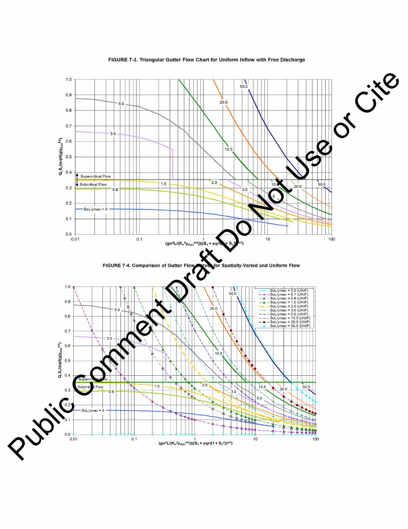
Public
Com
ment D
raft D
o Not
Use or
Cite

Public
Com
ment D
raft D
o Not
Use or
Cite
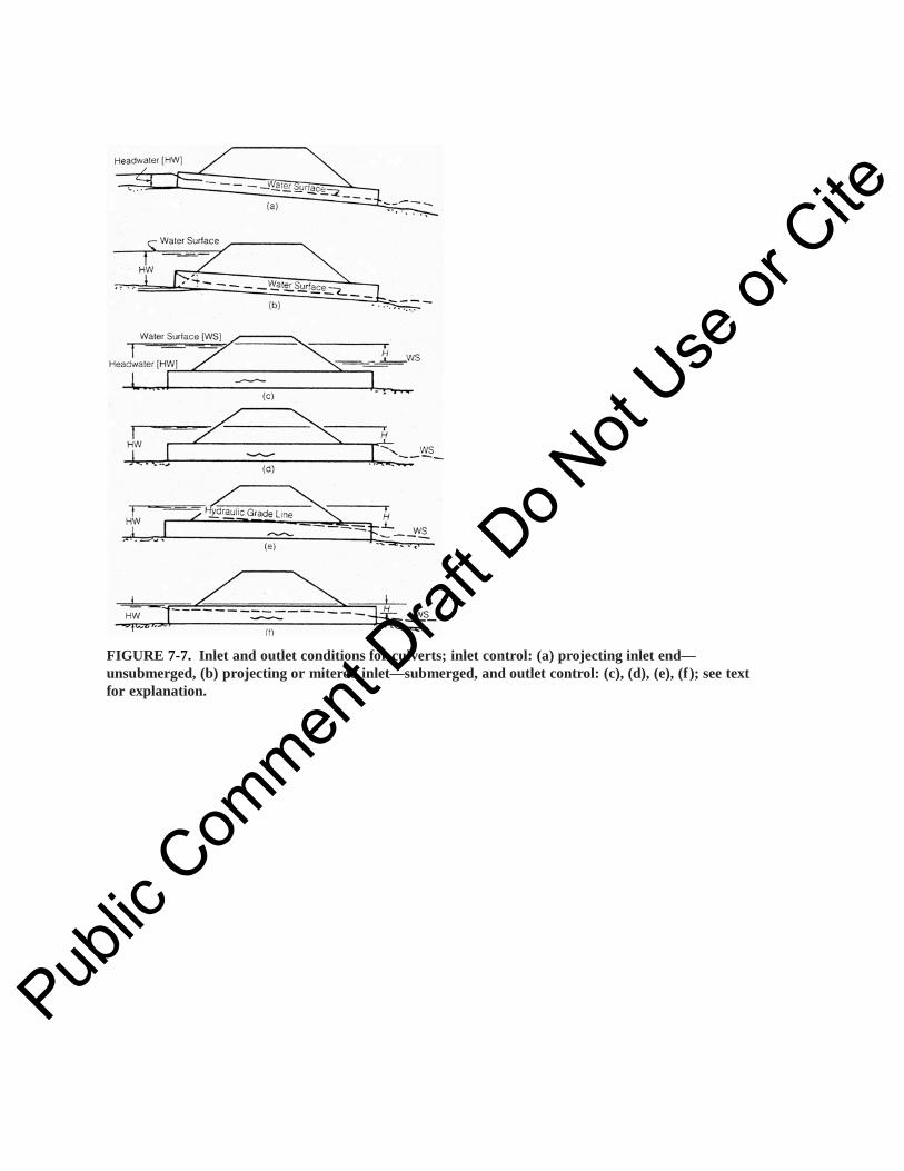
FIGURE 7-7. Inlet and outlet conditions for culverts; inlet control: (a) projecting inlet end—unsubmerged, (b) projecting or mitered inlet—submerged, and outlet control: (c), (d), (e), (f ); see text for explanation.
Public
Com
ment D
raft D
o Not
Use or
Cite

FIGURE 7-8. Types of flow encountered: (a) Type I Flow (subcritical), (b) Type IIA Flow (passes through critical), (c) Type IIB Flow (passes through critical), and (d) Type III Flow (supercritical) Source: FHWA 1978.
Public
Com
ment D
raft D
o Not
Use or
Cite

t
IQ
Rtc
t rtc
M
t*
Ip
Inflow hydrograph, I
Outflowhydrograph, Q
ts te FIGURE 7-9. Inflow and outflow hydrograph characteristics. Source: Graber 2010.
0
0.1
0.2
0.3
0.4
0.5
0.6
0.7
0.8
0.9
1
0.0 0.1 0.2 0.3 0.4 0.5 0.6 0.7 0.8 0.9 1.0
S*/V
i
M/Ip
FIGURE 7-10. S*/Vi vs. M/Ip and tr/tc
R = 1.67 except
tr/tc = 1.0
1 5 2.0 3.0 5.0
Infinite
ASCE/WEF (1992) for R
Public
Com
ment D
raft D
o Not
Use or
Cite

Source: Graber 2010.
Source: Graber 2010.
0
1000
2000
3000
4000
5000
6000
70000.0 1.0 2.0 3.0 4.0 5.0
0
20
40
60
80
100
120
140
160
180
0.00 0.02 0.04 0.06 0.08 0.10 0.12 0.14
S* (c
u ft)
M (cfs)
S* (m
3 )
M (m3/s)
FIGURE 7-11. Example maximum storage volume versus constant pumped outflow.
0
1000
2000
3000
4000
5000
0
10
20
30
40
50
60
70
80
90
100
110
120
130
140
150
0 5 10 15 20 25 30 35
Cum
ulat
ive
Volu
me
(cu
ft)
Cum
ulat
ive
Volu
me
(m3 )
Time (min.)
FIGURE 7-12. Mass curves for example problem.
Cumulative Inflow Volume
Cumulative Discharge Volume
45
Public
Com
ment D
raft D
o Not
Use or
Cite

Table 7-1. Recommended Design Values of Manning Roughness Coefficients for Closed Conduits and Open Channels
Source: ASCE/WEF 1992.
Conduit Material Manning’s n Closed conduits Asbestos-cement pipe Brick Cast iron pipe
Cement-lined and seal coated Concrete (monolithic)
Smooth forms Rough forms
Concrete pipe Corrugated-metal pipe Plain annular Plain helical
Paved invert Spun asphalt-lined Spiral metal pipe (smooth)
Ductile iron pipe (cement lined) Plastic pipe (corrugated) 3–8 in. (75–200 mm) diameter 10–12 in. (250–300 mm) diameter Larger than 12 in. (300 mm) diameter Plastic pipe (smooth interior) Vitrified clay
Pipes Liner plates
Open channels Lined channels
Asphalt Brick Concrete Rubble or riprap Vegetation
Excavated or dredged Earth, straight and uniform Earth, winding, fairly uniform Rock Not maintained
Natural channels (minor streams, top width at flood stage < 100 ft)
Fairly regular section Irregular section with pools
0.011–0.015 0.013–0.017
0.011–0.015
0.012 –0.014 0.015 – 0.017 0.011– 0.015
0.022 – 0.027 0.011 – 0.023 0.018– .0.022 0.011 – 0.015 0.012 – 0.015 0.011 – 0.014
0.014 –0.016 0.016 –0.018 0.019 –0.021 0.010 –0.013
0.011 – 0.015 0.013 – 0.017
0.013 – 0.017 0.012 – 0.018 0.011 – 0.020
See 7.3.6.2 0.030 – 0.40
0.020 – 0.030 0.025 – 0.040 0.030 – 0.045 0.050 – 0.14
0.03– 0.07 0.04 – 0.10
Public
Com
ment D
raft D
o Not
Use or
Cite

Table 7-2. Typical Form and Bend Loss Coefficients for Pipes A. Bend Losses (Values of KL in , the head loss in excess of that in a straight pipe of equal
length)
Radius of bend
Pipe diameter
Deflection angle of bend
90° 45° 22.5°
1 0.50 0.37 0.25
2 0.30 0.22 0.15
4 0.25 0.19 0.12
6 0.15 0.11 0.08
8 0.15 .011 0.08 B. Form Losses a. Enlargements
b. Abrupt Contractions
[Values of KL in
] (Values of KL in )
φ* KL
10 0.17 0.17 0 0.5 20 0.40 0.40 0.4 0.4 45 0.86 1.06 0.6 0.3 60 1.02 1.21 0.8 0.1 90 1.06 1.14 1.0 0 120 1.04 1.07 180 1.00 1.00 * The angle φ is between the sides of the tapering section
Pipe Entrance from reservoir
Bell mouth
Square-edge
Source: Linsley and Franzini 1972.
h K V gLm L= 2 2/
h K V V gLm L= −( ) /1 2
2 2 h K V gLm L= 2
2 2/
DD
2
1
3=DD
2
1
1 5= . DD
2
1
h VgL = 0 04
2
2
.
gVhL 2
5.02
=
Public
Com
ment D
raft D
o Not
Use or
Cite

Table 7-3. Hydraulic Data for Culvert: Culvert Entrance Losses Type of Entrance Entrance Coefficient, Ke
Pipe Headwall Grooved edge 0.20 Rounded edge (0.15D radius) 0.15 Rounded edge (0.25D radius) 0.10 Square edge (cut concrete and CMP) 0.40 Headwall & 45° Wingwall Grooved edge 0.20 Square edge 0.35 Headwall with Parallel Wingwalls Spaced 1.25D apart Grooved edge 0.30 Square edge 0.40 Beveled edge 0.25 Projecting Entrance Grooved edge (RCP) 0.25 Square edge (RCP) 0.50 Sharp edge, thin wall (CMP) 0.90 Sloping Entrance Mitered to conform to slope 0.70 Flared-end Section 0.50 Box, Reinforced Concrete Headwall Parallel to Embankment (no wingwalls) Square edge on 3 edges 0.50 Rounded on 3 edges to radius of 1/12 barrel dimension 0.20 Wingwalls at 30° to 75° to barrel Square edged at crown 0.40 Crown edge rounded to radius of 1/12 barrel dimension 0.20 Wingwalls at 10° to 30° to barrel Square edged at crown 0.50 Wingwalls parallel (extension of sides) Squared edged at crown 0.70 NOTE: The entrance loss coefficients are used to evaluate the culvert or sewer capacity operating under outlet control. Source: Urban Drainage and Flood Control District (2008)
Table 7-4. Stormwater Pumping Station Design Example
t r 50-year i 50-year i Ip Ip Vi Vi M = 0.0849 m3/s = 3 cfs
(min) t r /tc (mm/hr) i (in./hr) (m3/s) (cfs) Vi /(Iptc) m3 ft3 M/Ip t*/tc S*/Vi S*/(Iptc) S* (m3) S* (ft3)
5 0.833 195.6 7.700 0.188 6.658 1.168 79.3 2,800 0.451 1.751 0.353 0.413 28.0 990
6 (tc) 1.000 188.9 7.436 0.182 6.429 1.335 87.5 3,090 0.467 1.891 0.366 0.489 32.0 1,131 7 1.167 182.1 7.172 0.176 6.201 1.502 94.9 3,352 0.484 2.029 0.372 0.559 35.3 1,247
Public
Com
ment D
raft D
o Not
Use or
Cite

8 1.333 175.4 6.907 0.169 5.972 1.668 101.6 3,587 0.502 2.164 0.373 0.623 37.9 1,339 9 1.500 168.7 6.643 0.163 5.744 1.835 107.4 3,794 0.522 2.298 0.371 0.680 39.8 1,406 10 1.667 162.0 6.379 0.156 5.516 2.002 112.5 3,974 0.544 2.428 0.365 0.730 41.0 1,449 11 1.833 157.3 6.193 0.152 5.355 2.168 118.3 4,180 0.560 2.568 0.360 0.782 42.7 1,507 12 2.000 152.6 6.007 0.147 5.194 2.335 123.6 4,366 0.578 2.705 0.354 0.827 43.8 1,547 13 2.167 147.8 5.821 0.142 5.033 2.502 128.3 4,533 0.596 2.841 0.346 0.867 44.5 1,570 14 2.333 143.1 5.635 0.138 4.872 2.668 132.5 4,680 0.616 2.975 0.337 0.899 44.6 1,577 15 2.500 138.4 5.449 0.133 4.711 2.835 136.1 4,808 0.637 3.107 0.326 0.924 44.4 1,567 16 2.667 134.7 5.303 0.130 4.585 3.002 140.3 4,954 0.654 3.244 0.316 0.950 44.4 1,568 17 2.833 131.0 5.156 0.126 4.458 3.168 144.0 5,085 0.673 3.380 0.306 0.969 44.0 1,555 18 3.000 127.2 5.010 0.123 4.332 3.335 147.2 5,201 0.693 3.513 0.294 0.981 43.3 1,530 19 3.167 123.5 4.863 0.119 4.205 3.502 150.1 5,301 0.713 3.645 0.281 0.985 42.2 1,491 20 3.333 119.8 4.717 0.115 4.079 3.668 152.5 5,386 0.736 3.775 0.267 0.981 40.8 1,440 21 3.500 117.2 4.613 0.113 3.988 3.835 155.9 5,506 0.752 3.914 0.257 0.984 40.0 1,413 22 3.667 114.5 4.509 0.110 3.898 4.002 159.0 5,616 0.770 4.051 0.245 0.982 39.0 1,377 23 3.833 111.9 4.404 0.108 3.808 4.168 161.8 5,715 0.788 4.188 0.233 0.972 37.7 1,332 24 4.000 109.2 4.300 0.105 3.718 4.335 164.3 5,803 0.807 4.323 0.220 0.955 36.2 1,278 25 4.167 106.6 4.196 0.103 3.628 4.502 166.5 5,880 0.827 4.456 0.207 0.930 34.4 1,215 26 4.333 104.6 4.118 0.101 3.561 4.668 169.4 5,984 0.843 4.596 0.196 0.913 33.1 1,170 27 4.500 102.6 4.040 0.099 3.493 4.835 172.1 6,080 0.859 4.736 0.184 0.890 31.7 1,119 28 4.667 100.6 3.962 0.097 3.426 5.002 174.6 6,168 0.876 4.874 0.172 0.860 30.0 1,060 29 4.833 98.6 3.884 0.095 3.358 5.168 176.9 6,248 0.893 5.011 0.159 0.823 28.2 995
30 5.000 96.7 3.806 0.093 3.291 5.335 178.9 6,320 0.912 5.148 0.146 0.779 26.1 923
Note: Bold font corresponds to critical duration Source: Graber 2010.
Public
Com
ment D
raft D
o Not
Use or
Cite

FIGURE 8-2. Standard Installation.
FIGURE 8-3. Load schematic and pipe response for corrugated steel pipe.
Pub
lic C
ommen
t Draf
t Do N
ot Use
or C
ite

Table 8-1. Standard Installation Soil and Compaction Requirements Installation
Type
Bedding Thickness
Haunch and
Outer Bedding
Lower Side
Type 1 Do /24 minimum, not less than 75 mm (3" ).
95% Category I
90% Category I, 95% Category II,
If rock foundation, use or Do /12 minimum, not less
than 150 mm (6" ). 100% Category III
Type 2 Do /24 minimum, not less than 75 mm (3" ).
90% Category I or
85% Category I, 90% Category II,
If rock foundation, use 95% Category II or Do /12 minimum, not less
than 150 mm (6" ). 95% Category lIl
Type 3 Do /24 minimum, not less than 75 mm (3" ).
85% Category I, 90% Category II,
85% Category I, 90% Category II,
If rock foundation, use or or Do /12 minimum, not less
than 150 mm (6" ). 95% Category III 95% Category III
Type 4 Do /24 minimum, not less than 75 mm (3" ).
No compaction required, except if
No compaction required, except if
If rock foundation, use Category III, Category III, Do /12 minimum, not use 85% use 85%
Less than 150 mm(6”) Category III Category III
Notes: 1. Compaction and soil symbols—i.e., “95% Category I”— refers to Category I soil material with minimum standard Proctor compaction of 95%. See Table 8-2 for equivalent modified Proctor values. 2. Soil in bedding and haunch zones shall be compacted to at least the same compaction as specified for the majority of soil in the backfill zone.
Public
Com
ment D
raft D
o Not
Use or
Cite

Table 8-2. Equivalent USCS and AASHTO Soil Classifications for SIDD (Standard Installation Direct Design) Soil Designations
Representative Soil Types Percent Compaction
SIDD Soil
USCS
AASHTO
Standard Proctor
Modified Proctor
Gravelly SW, SP A1, A3 100 95 Sand GW, GP 95 90 (Category 1) 90 85 85 80 80 75 61 59 Sandy GM, SM, ML, A2, A4 100 95 Silt Also GC, SC 95 90 (Category II) with less than 20% 90 85 passing #200 sieve 85 80 80 75 49 46 Silty CL, MH, A5, A6 100 90 Clay GC, SC 95 85 (Category III) 90 80 85 75 80 70 45 40 CH 100 90 95 85
Source: ACPA 1990a, 1990b, 2004.
Table 8-3. Embankment Bedding Factors
Standard Installation Pipe Diameter Type 1 Type 2 Type 3 Type 4 300 mm (12 in.) 4.4 3.2 2.5 1.7 600 mm (24 in.) 4.2 3.0 2.4 1.7 900 mm (36 in.) 4.0 2.9 2.3 1.7 1,800 mm (72 in.) 3.8 2.8 2.2 1.7 3,600 mm (144 in.) 3.6 2.8 2.2 1.7 Notes: 1. For pipe diameters other than listed this table, embankment condition factors, Bfe can be obtained by interpolation. 2. Bedding factors are based on the soils being placed with the minimum compaction specified in Table 8-1 for each standard installation.
Table 8-4. Minimum (Trench) Bedding Factors
Standard Installation Minimum Bedding Factor, Bfo Type 1 2.3 Type 2 1.9 Type 3 1.7 Type 4 1.5
Notes: 1. Bedding factors are based on the soils being placed with the minimum compaction specified in Table 8-1 for each standard installation. 2. For pipe installed in trenches dug in previously constructed embankment, the load and the bedding factor should be determined as an
Public
Com
ment D
raft D
o Not
Use or
Cite

embankment condition unless the backfill placed over the pipe is of lesser compaction than the embankment
Table 8-5. Live Load Bedding Factors
Pipe Diameter, mm
Height, m
300
600
900
1,200
1,500
1,800
2,100
2,400
2,700
3,000
3,600
0.15 2.2 1.7 1.4 1.3 1.3 1.1 1.1 1.1 1.1 1.1 1.1 0.30 2.2 2.2 1.7 1.5 1.4 1.3 1.3 1.3 1.1 1.1 1.1 0.45 2.2 2.2 2.1 1.8 1.5 1.4 1 4 1 3 1.3 1.3 1.1 0.60 2.2 2.2 2.2 2.0 1.8 1.5 1.5 1.4 1 4 1.3 1.3 0.75 2.2 2.2 2.2 2.2 2.0 1.8 1.7 1.5 1.4 1.4 1 .3 0.90 2.2 2.2 2.2 2.2 2.2 2.2 1 8 1 7 1 5 1 5 1 4 1.05 2.2 2.2 2.2 2.2 2.2 2.2 1 9 1.8 1.7 1.5 1.4 1.20 2.2 2.2 2.2 2.2 2.2 2.2 2.1 1.9 1.8 1.7 1.5 1.35 2.2 2.2 2.2 2.2 2.2 2.2 2.2 2.0 1 9 1.8 1.7 1.50 2.2 2.2 2.2 2.2 2.2 2.2 2.2 2.2 2 0 1.9 1.8 1.65 2.2 2.2 2.2 2.2 2.2 2.2 2.2 2.2 2.2 2.0 1.9 1.80 2.2 2.2 2.2 2.2 2.2 2.2 2.2 2.2 2.2 2.1 2.0 1.95 2.2 2.2 2.2 2.2 2.2 2.2 2.2 2.2 2.2 2.2 2.2
NOTE: For pipe diameters other than listed in Table 8-5, BfLL values can be obtained by interpolation.
Public
Com
ment D
raft D
o Not
Use or
Cite
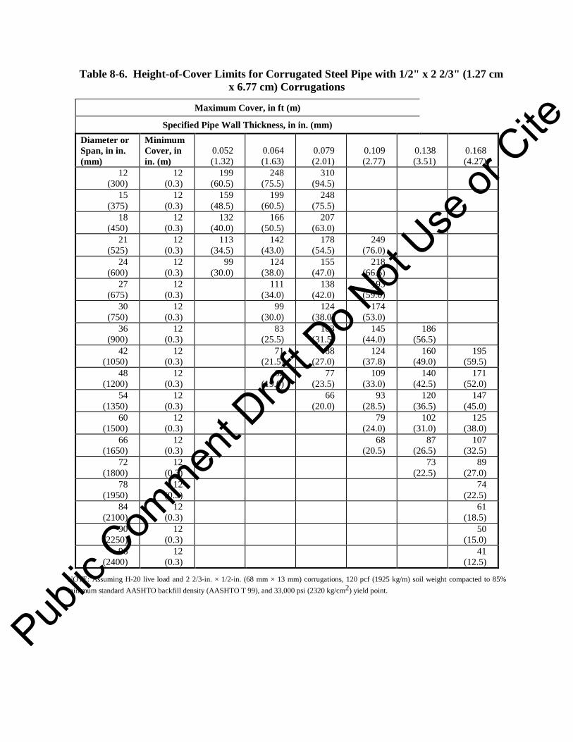
Table 8-6. Height-of-Cover Limits for Corrugated Steel Pipe with 1/2" x 2 2/3" (1.27 cm x 6.77 cm) Corrugations
Maximum Cover, in ft (m)
Specified Pipe Wall Thickness, in in. (mm) Diameter or Span, in in. (mm)
Minimum Cover, in in. (m)
0.052 (1.32)
0.064 (1.63)
0.079 (2.01)
0.109 (2.77)
0.138 (3.51)
0.168 (4.27)
12 (300)
12 (0.3)
199 (60.5)
248 (75.5)
310 (94.5)
15 (375)
12 (0.3)
159 (48.5)
199 (60.5)
248 (75.5)
18 (450)
12 (0.3)
132 (40.0)
166 (50.5)
207 (63.0)
21 (525)
12 (0.3)
113 (34.5)
142 (43.0)
178 (54.5)
249 (76.0)
24 (600)
12 (0.3)
99 (30.0)
124 (38.0)
155 (47.0)
218 (66.5)
27 (675)
12 (0.3)
111 (34.0)
138 (42.0)
193 (59.0)
30 (750)
12 (0.3)
99 (30.0)
124 (38.0)
174 (53.0)
36 (900)
12 (0.3)
83 (25.5)
103 (31.5)
145 (44.0)
186 (56.5)
42 (1050)
12 (0.3)
71 (21.5)
88 (27.0)
124 (37.8)
160 (49.0)
195 (59.5)
48 (1200)
12 (0.3)
62 (19.0)
77 (23.5)
109 (33.0)
140 (42.5)
171 (52.0)
54 (1350)
12 (0.3)
66 (20.0)
93 (28.5)
120 (36.5)
147 (45.0)
60 (1500)
12 (0.3)
79 (24.0)
102 (31.0)
125 (38.0)
66 (1650)
12 (0.3)
68 (20.5)
87 (26.5)
107 (32.5)
72 (1800)
12 (0.3)
73 (22.5)
89 (27.0)
78 (1950)
12 (0.3)
74 (22.5)
84 (2100)
12 (0.3)
61 (18.5)
90 (2250)
12 (0.3)
50 (15.0)
96 (2400)
12 (0.3)
41 (12.5)
NOTE: Assuming H-20 live load and 2 2/3-in. × 1/2-in. (68 mm × 13 mm) corrugations, 120 pcf (1925 kg/m) soil weight compacted to 85% minimum standard AASHTO backfill density (AASHTO T 99), and 33,000 psi (2320 kg/cm2) yield point.
Public
Com
ment D
raft D
o Not
Use or
Cite

Table 8-7. Bureau of Reclamation Values of E´ for Iowa Formula (Initial Flexible Pipe Deflection)
E´ for Degree of Compaction of Bedding (lb/in.2)
Soil Type-Pipe Bedding Material (Unified
Classification System) a
(1)
Dumped (2)
Slight, <85% Proctor, <40%
Relative Density (3)
Moderate, 85%–95% Proctor, 40%–70% Relative Density
(4)
High, >95% Proctor, >70% Relative Density
(5)
kPa (lb/in.2) kPa (lb/in.2) kPa (lb/in.2) kPa (lb/in.2) Fine-grained soils (LL > 50) b Soils with medium to high plasticity. (CH, MH, CH-MH)
No Data Available. Consult a Competent Soil Engineer. Otherwise use E´=0
Fine-grained soils (LL < 50) Soils with medium to no plasticity. (CL, ML, ML-CL) with less than 25% coarse-grained particles.
345 (50) 1,379 (200) 2,758 (400) 6,895 (1,000)
Fine-grained soils (LL < 50) Soils with medium to no plasticity. (CL, ML, ML-CL) with more than 25% coarse-grained particles. Coarse-grained soils with fines (GW, GP, SW, SP) c contains less than 12% fines
690 (100) 2,758 (400) 5,895 (1,000) 13,790 (2,000)
Coarse-grained soils with little or no fines (GW, GP, SW, SP) c contains less than 12% fines.
1,379 (200) 6,895 (1,000) 13,790 (2,000) 20,685 (3,000)
Crushed rock
6,895 (1,000)
20,685 (3,000) 20,685 (3,000) 20,685 (3,000)
Accuracy in terms of percentage deflection d
± 2 ± 2 ± 1 ± 0.5
NOTE: Values applicable only for fills less than 15 meters (50 ft). Table does not include any safety factor. For use in predicting initial deflections only, appropriate deflection lag factor should be applied for long-term deflections. If bedding falls on the borderline between two compaction categories, select lower E´ value or average the two values. Percentage Proctor based on laboratory maximum dry density from test standards using about 598,000 J/m3 (12,500 ft-lb/ft3) ASTM D698, AASHTO T 99, U.S. Bureau of Reclamation (USBR) Designation E-11 (Howard 1977).
aASTM Designation D2487, USBR Designation E-3 (Howard 1977). bLL = Liquid Limit. cOr any borderline soil beginning with one of these symbols (i.e., GM-GC, GC-SC, etc.) dFor 1% accuracy and predicted deflection of 3%, actual deflection would be between 2% and 4%.
Source: From Spangler, Merlin G., and Handy, Richard L, Soil Engineering, New York; Harper & Row, 1982, page 794. Used with permission.
Public
Com
ment D
raft D
o Not
Use or
Cite

Table 8-8. Typical* Pipe Properties for AASHTO M252 and M294 (HDPE Pipe)
Nominal Diameter
in in. (mm)
Typical Outside Diameter (OD) in in. (mm)
Minimum Pipe Stiffness, Pii
(kPa)
Cross-Sectional Area, as in.²/in. (mm2/mm)
Distance from Inside Diameter to Neutral Axis
(C) in in. (mm)
Moment of Inertia (I) in.4/in. (mm4/mm)
3 (75) 3.6 (91) 35 (241) 0.0448 (1.138) 0.1528 (3.881) 0.0004 (6.55)
4 (100) 4.6 (117) 35 (241) 0.0568 (1.443) 0.1917 (4.869) 0.0007 (11.47)
6 (150) 7.0 (178) 35 (241) 0.0837 (2.126) 0.3158 (8.021) 0.0033 (54.08)
8 (200) 9.9 (251) 35 (241) 0.1044 (2.652) 0.4345 (11.036) 0.0087 (142.57)
10 (250) 11.9 (302) 35 (241) 0.1117 (2.837) 0.5319 (13.510) 0.0185 (303.16)
12 (300) 14.0 (356) 50 (344) 0.1250 (3.175) 0.6250 (15.875) 0.0240 (393.29)
15 (375) 17.7 (450) 42 (289) 0.1592 (4.044) 0.8750 (22.225) 0.0530 (868.51)
18 (450) 21.1 (536) 40 (276) 0.1950 (4.953) 0.8510 (21.615) 0.0620 (1016.00)
24 (600) 27.5 (699) 34 (235) 0.2617 (6.647) 1.1340 (28.804) 0.1160 (1900.90)
30 (750) 34.1 (866) 28 (193) 0.3267 (8.298) 1.3500 (34.290) 0.1630 (2671.09)
36 (900) 41.0 (1041) 22 (152) 0.3750 (9.525) 1.6500 (41.910) 0.2220 (3637.93)
42 (1050) 48.0 (1219) 20 (138) 0.3906 (9.921) 1.7800 (45.212) 0.5742 (9409.45)
48 (1200) 54.0 (1372) 17 (117) 0.4294 (10.902) 1.8600 (47.244) 0.6919 (11338.21)
*These values are intended to represent typical measurements for a range of commercially available products. They should not be interpreted to represent minimum or maximum values unless stated. Contact the pipe manufacturer for specific information.
Table 8-9. Shape Factors (Df)
Gravel Sand
Pipe Stiffness, Psi (kPa)
Dumped to Slight
Moderate to High
Dumped to Slight
Moderate to High
9 (62) 5.5 7.0 6.0 8.0
18 (124) 4.5 5.5 5.0 6.5
36 (248) 3.8 4.5 4.0 5.5
72 (496) 3.3 3.8 3.5 4.5
NOTE: Please interpolate for intermediate pipe stiffness values.
Public
Com
ment D
raft D
o Not
Use or
Cite

Standard ASCE 46-XX / DRAFT 1
A S C E S TANDA R D ASCE/EWRI 46-XX
American Society of Civil Engineers Standard Guidelines for the Installation of Urban Stormwater Systems
Public
Com
ment D
raft D
o Not
Use or
Cite

Standard ASCE 46-XX / DRAFT 2
CONTENTS
Foreword .........................................................................................................................................
Acknowledgments .............................................................................................................................
1 Scope ...................................................................................................................................
2 Definitions ............................................................................................................................
3 Contract Documents...............................................................................................................
3.1 Plans ........................................................................................................................
3.2 Specifications .............................................................................................................
3.3 Other ........................................................................................................................
4 Reconstruction Site Inspection ..............................................................................................
4.1 Surface Features .........................................................................................................
4.2 Subsurface Features ...................................................................................................
4.2.1 Utilities ...........................................................................................................
4.2.2 Geologic Conditions ...................................................................................
5 Construction
5.1 Safety ......................................................................................................................
5.2 Soil Erosion and Sediment Control ..........................................................................
5.3 Site Preparation .........................................................................................................
5.4 Materials Receiving, Handling, and Storage .........................................................
5.5 Line and Grade ...........................................................................................................
5.6 Excavation ................................................................................................................
5.6.1 Excavation Limits .......................................................................................
5.6.2 Handling of Excavated Material ...................................................................
5.6.3 Sheathing and Shoring .................................................................................
5.6.4 Dewatering .................................................................................................
5.7 Foundation Preparation ..........................................................................................
Public
Com
ment D
raft D
o Not
Use or
Cite

Standard ASCE 46-XX / DRAFT 3
5.8 Placement of Drainage Materials .............................................................................
5.8.1 Pipe ...............................................................................................................
5.8.2 Geocomposite Drainage Materials .................................................................
5.8.3 Other Drainage Materials .............................................................................
5.9 Backfill .....................................................................................................................
5.10 Site Restoration .........................................................................................................
6 Inspection
6.1 Inspection of Materials ..........................................................................................
6.1.1 Prefabricated or Premanufactured Components ..........................................
6.1.2 Bedding, Backfill, and Envelope Materials ................................................
6.1.3 Storage of Materials ....................................................................................
6.2 Inspection of Equipment ........................................................................................
6.2.1 Safety ............................................................................................................
6.2.2 Suitability and Conformance .........................................................................
6.3 Inspection of Construction ......................................................................................
6.3.1 Sequencing .................................................................................................
6.3.2 Construction Layout ....................................................................................
6.3.3 Excavation and Dewatering .........................................................................
6.3.4 Construction ...............................................................................................
6.3.5 Backfilling......................................................................................................
6.3.6 Televising .......................................................................................................
6.3.7 Testing ...........................................................................................................
6.4 Acceptance of Construction ....................................................................................
6.5 Recording Observations ..........................................................................................
6.6 Record Drawings ......................................................................................................
7 References
Appendix I. Inspector’s Checklist for Preliminary Inspection Activities ........................................
Appendix II. Inspector’s Checklist for Construction Procedures ..................................................... Pub
lic C
ommen
t Draf
t Do N
ot Use
or C
ite

Standard ASCE 46-XX / DRAFT 4
Index ..........................................................................................................................................105
Public
Com
ment D
raft D
o Not
Use or
Cite

Standard ASCE 46-XX / DRAFT 5
FOREWORD
The Board of Direction approved revisions to the ASCE Rules for Standards Committees to govern the writing and maintenance of standards developed by ASCE. All such standards are developed by a consensus standards process managed by the ASCE Codes and Standards Committee (CSC). The consensus process includes balloting by a balanced standards committee and reviewing during a public comment period. All standards are updated or reaffirmed by the same process at intervals between five and 10 years. Requests for formal interpretations shall be processed in accordance with Section 7 of ASCE Rules for Standards Committees, which are available at www.asce.org. Errata, addenda, supplements, and interpretations, if any, for these standard guidelines also can be found at www.asce.org.
The Standard Guidelines for the Installation of Urban Stormwater Systems is a companion to the Standard Guidelines for the Design of Urban Stormwater Systems and Standard Guidelines for the Operation and Maintenance of Urban Stormwater Systems. These standard guidelines were developed by the Urban Drainage Standards Committee, which is responsible to the Environmental and Water Resources Institute of the American Society of Civil Engineers.
The provisions of this document are written in permissive language and, as such, offer to the user a series of options or instructions but do not prescribe a specific course of action. Significant judgment is left to the user of this document.
These standard guidelines may involve hazardous materials, operations, and equipment. These standard guidelines do not purport to address the safety problems associated with its application. It is the responsibility of whoever uses these standard guidelines to establish appropriate safety and health practices and to determine the applicability of regulatory and nonregulatory limitations.
These standard guidelines have been prepared in accordance with recognized engineering principles and should not be used without the user’s competent knowledge for a specific application. The publication of these standard guidelines by ASCE is not intended to warrant that the information contained therein is suitable for any general or specific use, and ASCE takes no position respecting the validity of patent rights. The user is advised that the determination of patent rights or risk of infringement is entirely his or her own responsibility.
Public
Com
ment D
raft D
o Not
Use or
Cite

Standard ASCE 46-XX / DRAFT 6
ACKNOWLEDGMENTS
The American Society of Civil Engineers (ASCE) acknowledges the work of the Urban Drainage
Standards Committee of the Environmental and Water Resources Institute of ASCE (EWRI of
ASCE).
This group comprises individuals from many backgrounds, including consulting engineering,
research, construction industry, education, and government. Those individuals who serve on the
Urban Drainage Standards Committee are
William Curtis Archdeacon, P.E., R.L.S., Past Chair
Kathlie Jeng-Bulloch, Ph.D., P.E., D.WRE, CFM, M.ASCE, Chair
William P. Bulloch, P.E., M.ASCE
Christopher B. Burke, Ph.D., P.E., D.WRE, F.ASCE
James C.-I. Chang, Ph.D., P.E.
Richard Field, P.E., D.WRE, BCEE, M.ASCE
Robert S. Giurato
Jeffrey S. Glenn, P.E., D.WRE, CFM, F.ASCE
S. David Graber, P.E., F.ASCE, Vice Chair & Corresp.Editor
Jay M. Herskowitz, P.E., M.ASCE
Conrad G. Keyes, Jr., Ph.D., P.E., L.S., D.WRE, Dist.M.ASCE
James H. Lenhart, Jr., P.E., D.WRE, M.ASCE
Lawrence M. Magura, P.E., M.ASCE, Secretary
Garvin J. Pederson, P.E., M.ASCE
Anthony N. Tafuri, P.E., D.WRE, M.ASCE
Kenneth E. Waite, P.E., M.ASCE
Keh-Han Wang, Ph.D., M.ASCE Pub
lic C
ommen
t Draf
t Do N
ot Use
or C
ite

Standard ASCE 46-XX / DRAFT 7
William J. Weaver, P.E., M.ASCE
Donald E. Woodward, P.E., F.ASCE
The corresponding editor recognizes the following committee members who were particularly
helpful in updating the standard guidelines: Jeffrey S. Glenn, Conrad G. Keyes, Jr., James H.
Lenhart, Kenneth E. Waite, William J. Weaver, and Donald E. Woodward.
Public
Com
ment D
raft D
o Not
Use or
Cite

Standard ASCE 46-XX / DRAFT 8
Chapter 1
SCOPE
The intent of this standard is to present construction guidance for urban stormwater systems. It
updates ASCE/EWRI 46-05 Standard Guidelines for the Installation of Urban Stormwater
Systems with material developed within the past eight years. The collection and conveyance of
surface stormwaters are within the purview of this standard for applications such as airports;
roads and other transportation systems; and industrial, residential, and recreation areas. This
document is intended for guidance during the urban stormwater system construction phase for
the engineer, project manager, inspector, and contractor.
Public
Com
ment D
raft D
o Not
Use or
Cite

Standard ASCE 46-XX / DRAFT 9
Chapter 2
DEFINITIONS
This section defines specific terms for use in these guidelines. References included in 11.0 of
ASCE/EWRI 45 also may be helpful in understanding the terms used in these guidelines.
Envelope—Permeable material placed around a pipe or drainage product to improve flow and
soil filtration conditions in the area immediately adjacent to the drain and for improving
bedding and structural backfill conditions.
Geomembrane—Sheet material intended to form an impermeable barrier.
Geosynthetic—Generic term for synthetic material or structure used as an integral part of a
project, structure, or system. Within this category are subsurface drainage and water
control products, such as geomembranes, geotextiles, and geocomposites.
Geotextile—Woven or nonwoven thermoplastic sheet material intended to allow the passage of
water, but not fines, and without collecting fines at the soil–textile interface.
Grade—May refer to either (1) the slope of the drain in vertical units or horizontal units, or (2)
the specified vertical location of the drain, depending on the context in which it is used.
ID—Inner diameter of a pipe measured from inside the wall. Sometimes the actual ID varies
from the nominal ID.
OD—Outer diameter of a pipe measured from outside the wall.
OSHA— Occupational Safety and Health Administration, the U.S. federal agency responsible
for safety and health concerns on construction jobsites and in the workplace.
ROW—Right-of-way, which is a distance of public access.
Subsurface Water—All water beneath the ground or pavement surface. Usually referred to as
groundwater.
Public
Com
ment D
raft D
o Not
Use or
Cite

Standard ASCE 46-XX / DRAFT 10
Chapter 3
CONTRACT DOCUMENTS
The construction contract includes the following documents: Contract Form; General, Special,
and Supplemental Conditions; Plans and Specifications; Bid Form; and Bond and Insurance
Requirements. Special reports, such as subsurface exploration and hydrology and copies of
relevant governmental permits, often are included as well.
3.1 PLANS
Plans are contract drawings, prepared to a scale, showing the proposed surface drainage system
and known surface and subsurface features that may affect the construction. The plans typically
show type, size, material, grade, and location of the drainage system in plan and profile views.
Different plan sheets can be used to illustrate different construction phases, such as clearing,
grading, sediment and erosion control features, utility plans (including storm drainage systems),
final grade plans showing locations and rim elevations of drainage features, and callouts for best
management practice (BMP) construction details.
3.2 SPECIFICATIONS
Specifications are written text and details that provide specifics of the construction. They
typically detail all appropriate standards required for the product and project. Construction
methods may be specified on a case-by-case basis.
3.3 OTHER
Many other publications are made part of the contract documents by reference only, such as
government requirements, permits, reports, or trade and industry specifications. Some of these
reports will include soil borings, past construction observations, and studies.
Public
Com
ment D
raft D
o Not
Use or
Cite

Standard ASCE 46-XX / DRAFT 11
Chapter 4
PRECONSTRUCTION SITE INSPECTION
It is necessary to examine the plans and specifications and make a personal examination of the
site and its surroundings prior to construction. This inspection should include reviews of both
surface and subsurface features. (See Appendix I, Inspector’s Checklist for Preliminary
Inspection Activities.) This is especially important if the site is subject to low impact
development (LID) design and construction approaches that seek to preserve existing vegetation
and natural drainage features while minimizing soil compaction.
4.1 SURFACE FEATURES
The surface features of the site should have been located through a topographic survey and
shown in the plans. The plans should be compared with existing field conditions to determine
whether there are any differences between the topographic survey and present conditions.
Discrepancies are to be brought to the attention of the engineer or project manager.
4.2 SUBSURFACE FEATURES
Subsurface features principally consist of utilities, water table level, and geologic conditions. All
subsurface features affecting the work should have been determined and shown in the plans.
Methods for identifying such features are discussed in 3.1.1 of the companion Standard
Guidelines for the Design of Urban Stormwater Systems. If called for in the plans, the contractor
should undertake a program of field surveys and test pits to verify subsurface conditions at
specific locations identified in the plans. In all cases, the contractor should immediately notify
the engineer of changed conditions and should not commence construction of work in areas
where discrepancies are noted until the engineer has issued written clarification.
4.2.1 Utilities
The location and size of sanitary sewers, drains, culverts, gas lines, water mains, electric lines,
telephone conduits, and other underground utilities and structures should be shown in the plans. Public
Com
ment D
raft D
o Not
Use or
Cite

Standard ASCE 46-XX / DRAFT 12
This information should have been obtained from both field surveys and other available records.
Utility locating organizations are usually available in urban areas to mark the position of lines.
4.2.2 Geologic Conditions
All appropriate and available geologic conditions should have been shown or noted in the plans.
An assessment should have been made with respect to rock and groundwater conditions.
Public
Com
ment D
raft D
o Not
Use or
Cite

Standard ASCE 46-XX / DRAFT 13
Chapter 5
CONSTRUCTION
Prior to construction, all documents, including plans and specifications, subsurface information,
standard details, product shop drawings, and special provisions should be reviewed and any
questions resolved. All materials should be inspected before they are used in the work. Materials
not meeting contract requirements, as determined by visual inspection, certification, or testing,
should be rejected. Communication procedures among the owner, engineer, and contractor
should be established clearly prior to construction as provided for in the contract documents. All
significant project activity—including daily inspections, and requests for changes in materials,
procedures, designs, cost or schedule—should be communicated in writing.
Construction should begin at the downstream terminus of the stormwater system (outlet) unless
otherwise approved and proceed upstream to the uppermost terminus. The contractor should take
the utmost care to protect the completed portions of the stormwater system if rainstorms occur
during construction. It should be the contractor’s responsibility to either bypass storm flows
around the construction site or pass the flows safely through the completed portions of the
stormwater system.
The design engineer may have specified when the contractor can construct the outlet works and
detention facilities, depending on when peak flows are anticipated.
5.1 SAFETY
The contractor is responsible for construction site safety. Federal regulations covering safety for
all types of construction are published in the Safety and Health Regulations for Construction
under the U.S. Department of Labor, Occupational Safety and Health Administration (OSHA).
Many states, municipalities, and other local agencies have established codes of safe practice
regarding construction. Typical construction activities include excavation and backfilling, but
also can include tunneling and, on rare occasions, blasting. In the United States, the regulations
apply to all these types of construction, as well as alteration and repair work. All personnel Public
Com
ment D
raft D
o Not
Use or
Cite
Standard ASCE 46-XX / DRAFT 14
associated with the construction should be familiar with the requirements applicable to drainage
system projects, especially in regard to safe trenching procedures.
The contractor has the authority and the responsibility for keeping unauthorized persons away
from hazardous activity on the jobsite. Any people allowed by the contractor on-site should be
supplied with hard hats and other appropriate personal protective equipment. Their movement
around the jobsite should be restricted as necessary to ensure their safety.
5.2 SOIL EROSION AND SEDIMENT CONTROL
Proper planning and scheduling of construction activities are major factors in controlling erosion
and sediment pollution. Erosion and sediment control at the site should be in accordance with
federal, state, municipal, and local agency regulations, and as otherwise established by the
contract plans and specifications.
5.3 SITE PREPARATION
Site preparation should be in accordance with the contract plans and specifications and may
include top- soil stripping, clearing and grubbing, pavement and sidewalk removal, rough
grading, protection or relocation of existing natural drainage, removal of unsuitable soil material,
construction of access roads, detours, and protection or relocation of existing structures and
utilities. (See Appendix I, Inspector’s Checklist for Preliminary Inspection Activities.)
5.4 MATERIALS RECEIVING, HANDLING, AND STORAGE
The contractor is responsible for proper receiving, handling, and storage of all construction
materials for the project. Materials damaged in shipment or at the site that cannot be repaired
should be marked or tagged and removed from the site. All materials should be unloaded and
handled with reasonable care.
Materials should be stockpiled as near as possible to where they will be installed, consistent with
municipal requirements, safety, and environmental considerations. All materials should be stored
as recommended by the manufacturer. All materials should be stockpiled in a safe manner. Public
Com
ment D
raft D
o Not
Use or
Cite

Standard ASCE 46-XX / DRAFT 15
5.5 LINE AND GRADE
The contractor is responsible for maintaining all line and grade, monuments, control points, and
stakes set by the surveyor until the project is completed and accepted.
All surface stormwater systems should be installed true to line and grade in accordance with the
contract plans and specifications. Adjustments to correct departures from specified line, and
grade should not exceed those permitted by contract documents or manufacturers’
recommendations, whichever are more restrictive, provided that such corrections never result in
a reversal of the slope in the drainage system. Moreover, realignments never should result in
damage to any flexible drainage materials or a reduction in the flow capacity of the system. The
return to specified line and grade should be made by adding or removing bedding material, and
the use of wedges or blocks is unacceptable. The maximum allowable departure from the
horizontal alignment should be specified by the contract documents. Departure distances should
be determined by measurement along common elements of the planned versus actual installation,
such as centerline-to-centerline measurements.
5.6 EXCAVATION
Excavation should be in accordance with contract plans and specifications and may include
trenching, backfilling, embankment construction, soil stabilization, and control of groundwater
and surface drainage. Adequate knowledge of subsurface conditions is required for all types of
excavation. Additional exploration and analysis are recommended if the subsurface information
in the plans is insufficient. The contractor should recognize latent conditions that are different
from those described in the contract documents. The contractor also should notify the owner and
the state or other appropriate historic preservation officer if archaeological items are encountered
during construction.
5.6.1 Excavation Limits
Excavation, installation, and backfill operations should be performed in a timely manner to
reduce open trench time. The length of open trench should comply with limits established by the
contract documents and applicable federal, state, and local regulations. Specified trench width
requirements for conduits should be maintained to ensure proper backfill construction. Trench Pub
lic C
ommen
t Draf
t Do N
ot Use
or C
ite

Standard ASCE 46-XX / DRAFT 16
depth and width should be in accordance with the contract plans and specifications. If the trench
width becomes greater than specified, the contractor should contact the engineer for a
reevaluation of the required pipe strength, bedding materials and methods, and backfilling
procedures to be used. (See Fig. 5-1, typical pipe installation.)
5.6.2 Handling of Excavated Material
Excavated material to be used as backfill should be stockpiled in accordance with the contract
plans and specifications and applicable safety regulations a safe distance back from the edge of
the trench. Generally, if trench walls are unsupported, the minimum distance from the trench side
to the excavated material should be either 3 ft (1 m) or half of the trench depth, whichever is
greater. If the trench walls are supported, the usual minimum distance from the trench side to the
excavated material should be 3 ft (1 m).
These general recommendations should not supersede job-specific requirements in the presence
of unstable soils or the potential for accumulation of water in the trenches.
For trencher installations where drainage material and backfill are placed simultaneously and
where personnel are not allowed in the trench, soil placement may be unrestricted. Unused
excavated materials should be disposed of in accordance with contract documents.
5.6.3 Sheathing and Shoring
OSHA and many states, municipalities, and other local agencies have established codes of safe
practice regarding support requirements for trench excavation. When required by established
codes, sheathing and shoring should be adequate to prevent cave-in of the trench walls or
subsidence of areas adjacent to the trench, and to prevent sloughing of the base of the excavation.
Sheathing and shoring should not extend into the soil envelope zone of the pipe or geocomposite
drainage system. Any sheathing placed below the top of the drainage product of flexible pipes or
geocomposite materials or the spring line of rigid pipes should remain in place after backfilling.
Movement of shoring following backfill placement may reduce the structural integrity of the
surrounding embedment material.
Public
Com
ment D
raft D
o Not
Use or
Cite

Standard ASCE 46-XX / DRAFT 17
The contractor is responsible for adequacy of any required sheathing and shoring. The strength
of support systems should be based on the principles of geotechnical and structural engineering
as applicable to the materials encountered.
5.6.3.1 Trench Boxes with Subtrench
Trench boxes provide a safer work area to install pipe in deep trenches or in soils that have
insufficient stability. Use of a trench box also may be required by the specifications for reasons
other than safety. Whereas trench boxes will work for most cohesive and noncohesive native
soils, highly unusual soil conditions may require further investigation. Some installations may
not require trench boxes if the trench sidewall can be sloped. The engineer should provide
specific guidance on acceptable slopes, but in no case should the trench wall slope be greater
than the angle of repose of the native soil. The length of the trench box should be suitable for the
pipe length.
The most effective way to maintain a sound subtrench system is to provide a subtrench within
which to place the pipe and backfill.
Backfill and compact according to the design specifications within the subtrench. The trench box
can be pulled along the top edge of the subtrench (Fig. 5-2) without affecting the pipe or the
backfill. Subtrench construction also makes it easier to use a geotextile around the backfill if it is
required by the project specifications. Line the subtrench with the geotextile, place the pipe and
backfill, and wrap the geotextile over the top of the pipe and backfill system within the trench
box.
5.6.3.2 Trench Boxes without Subtrench
In construction not involving a subtrench situation, dragging a trench box subjects the pipe to
stretching or a separated joint. The box should be lifted vertically until it is above the pipe and
reset into its new position. If it is necessary for a trench box to be dragged through a trench, do
not lower the box more than one-fourth of the nominal diameter below the crown (top) of the
pipe. This allows the backfill material to flow out of the bottom of the box around the pipe so
that backfill disturbance is kept to a minimum. An alternative for flexible stormwater system
when the box will be dragged is to use a well-graded granular backfill material two diameters on
either side of the pipe and compact it to a minimum of 90% standard Proctor density before Pub
lic C
ommen
t Draf
t Do N
ot Use
or C
ite

Standard ASCE 46-XX / DRAFT 18
moving the box. Immediately fill the area between the pipe and backfill structure and the trench
wall with a granular material. If the project requires a geotextile around the backfill, use a well-
graded granular backfill material and compact it to at least 90% standard Proctor density. Do not
drag the box; instead, lift it vertically. After the trench box is removed, immediately fill the area
between the pipe and backfill structure and the trench wall with a granular material and compact
according to project requirements. The geotextile manufacturer may be able to provide additional
information regarding the suitability of specific geotextiles for use with trench boxes. Although
trench boxes increase worker safety in difficult site conditions, precautions are required to ensure
a structurally sound pipe and backfill system. Construction of a subtrench is the most effective
means of maintaining a sound system. When a regular trench is used, techniques, such as lifting
the box, keeping the box about three-fourths the nominal diameter up from the trench bottom,
and providing a wide granular backfill envelope, will help provide a quality construction.
5.6.4 Dewatering
When necessary, all excavations should be dewatered prior to and during installation and
backfilling of the surface drainage. The contractor is responsible for dewatering operations and
compliance with related project specifications and should ensure that foundation and bedding
materials are not being removed through the dewatering system or that environmental or
property damage does not result.
5.7 FOUNDATION PREPARATION
Bedding for surface drainage systems should be as specified and completed to design line and
grade.
The intrusion of foreign material into any portion of the drainage system because of construction
and weather events should be prevented until the system is protected adequately by backfill.
5.8 PLACEMENT OF DRAINAGE MATERIALS
The placement of pipe, geocomposite materials, and other drainage materials is covered in the
following sections. Public
Com
ment D
raft D
o Not
Use or
Cite

Standard ASCE 46-XX / DRAFT 19
5.8.1 Pipe
A bedding material should be placed on the foundation, the pipe laid and connected, and backfill
placed, all in accordance with the contract plans and specifications.
5.8.2 Geocomposite Drainage Materials
Prefabricated geocomposite surface collector drains may be placed in trenches by hand or
machine. Construction methods should not cause damage to the interior core and geotextile
overwrap, including any factory-made seams and connections. Joints should be made using
connectors recommended by the manufacturer or in accordance with the contract plans and
specifications. Producers of geocomposite material generally provide construction guidelines to
be followed. All joints should be made soil-tight using tape, glue, or other sealing procedures
recommended by the manufacturer or in accordance with the contract plans and specifications. In
all cases, such sealing procedures should provide ensured long-term resistance to degradation in
wet subsurface environments.
5.8.3 Other Drainage Materials
Geomembranes, geotextiles, aggregates, and pump and lift stations should be installed in
accordance with the contract plans and specifications.
5.9 BACKFILL
Backfill material should be placed and compacted in accordance with the contract plans and
specifications. Backfill should not be dumped or dropped directly on any portion of the drainage
system. Heavy equipment operations should be controlled so as not to damage any portion of the
drainage system. Backfill material should be placed in layers in accordance with contract
documents and compacted at or near optimum moisture content or to specified densities.
5.10 SITE RESTORATION
Restoration of grass, shrubs, and other plantings should be performed in accordance with
contract documents. Until revegetation is complete, adequate protection against erosion and
runoff is necessary and should be in accordance with the contract documents and governing Public
Com
ment D
raft D
o Not
Use or
Cite

Standard ASCE 46-XX / DRAFT 20
regulations. All revegetation and tree repair should be in accordance with accepted horticultural
practice.
When replacing permanent pavement, the subgrade must be restored and compacted until smooth
and to specified densities. Thickness and type of pavement should be as established by contract
documents and applicable regulations.
Public
Com
ment D
raft D
o Not
Use or
Cite

Standard ASCE 46-XX / DRAFT 21
Chapter 6
INSPECTION
The duty of the inspector is to observe and report on the materials furnished and the work
performed to evaluate full compliance with the contract documents. A qualified inspector should
be on-site to observe all phases of the site preparation, materials receiving and handling,
installation, and site restoration. Observations of materials, workmanship, and, where specified
in the contract documents, methods and means of performing construction are required to
determine compliance with contract documents. It is not the function of the inspector to
supervise or direct the manner in which the work is performed.
The inspector should have unrestricted access to all areas where the preparation of the materials
and parts of work to be done are carried out and conducted. The contractor should provide access
to all facilities and assistance required to perform the inspection. (See Appendix II, Inspector’s
Checklist for Construction Procedures.)
6.1 INSPECTION OF MATERIALS
All construction materials must be inspected carefully and thoroughly prior to and during
placement. Inspection should be an ongoing process, because satisfactory materials first arriving
on-site can be damaged during handling, storage, and installation. No material of any kind
should be used prior to inspection and formal approval.
Project specifications and other product-specified information should form the basis for
determining the suitability of all materials. Should any doubt concerning suitability arise, the
product manufacturer should be consulted. Shipments of select fill materials and drainage
products should be accompanied by certified test reports. If such data are missing, laboratory
tests should be used to confirm appropriate properties.
All drainage products or drainage system components should be measured to check size, shape,
and fit. Public
Com
ment D
raft D
o Not
Use or
Cite

Standard ASCE 46-XX / DRAFT 22
All materials should be inspected to ensure that they are free of foreign deposits, defects, and
damage. Cleaning and removal of foreign matter may be acceptable, provided there is complete
assurance that the construction material or product is unharmed and in “like new” condition.
Damaged products or components should be removed immediately from the site. Repairs may be
performed on damaged goods following inspection and approval by the inspector and after
consultation with the manufacturer. The return of any previously rejected materials, products, or
components to the site is acceptable only after reinspection and approval following rework. Any
material or workmanship found at any time during the construction cycle not in accordance with
project specifications, for any reason, should be remedied immediately.
6.1.1 Prefabricated or Premanufactured Components
Prior to construction, all prefabricated and/or premanufactured components should be inspected
to establish conformity with the project specifications and to check for damage and the presence
of foreign matter. The manufacturer’s certificate of compliance and product drawings should
confirm compliance with the contract documents.
6.1.2 Bedding, Backfill, and Envelope Materials
The inspection of all materials for use in bedding, backfilling, and envelope materials, or as
otherwise used in surface drainage systems, should be checked for conformance to project
specifications. The supplier’s certificate of compliance should form the basis of the inspection.
Geosynthetic products should be inspected for damage and conformity to the project plans and
specifications. The manufacturer’s materials certificate should be the basic inspection document.
Any deviations from the contract specifications should be immediately referred to the project
engineer.
6.1.3 Storage of Materials
Storage of materials should be managed by the contractor to avoid impairing the usability and
quality of on-site materials. Observance of any special handling methods required should be
verified and recorded. Public
Com
ment D
raft D
o Not
Use or
Cite
Standard ASCE 46-XX / DRAFT 23
Storage or special protection required by the contract documents for certain items also should be
verified. Storage, especially topsoil and landscaping, should be in a manner that minimizes
effects from rainfall and runoff. The inspector is responsible for monitoring the contractor’s
observance of these requirements.
6.2 INSPECTION OF EQUIPMENT
All equipment used in the construction of the project should be subject to inspection and testing
where applicable.
6.2.1 Safety
All reasonable safety rules established by the contractor should be obeyed. Observations should
be performed in a manner that will not unreasonably impede or obstruct the contractor’s
operations.
6.2.2 Suitability and Conformance
Methods and means of construction are left to the option of the contractor on most items to allow
flexibility but may be specified on items where methods and means are critical to obtaining a
final desired product. Although means and methods may not be specified in full detail, minimum
elements frequently are identified. Where methods and means are specified in the contract
documents, verification is required for compliance.
6.3 INSPECTION OF CONSTRUCTION
The portions of inspection of construction that are covered in the following include sequencing,
construction layout, excavation and dewatering, construction, backfilling, televising, and testing.
6.3.1 Sequencing
The sequence of construction operations is an important consideration in projects that require
construction in a particular order. Sequencing also may be required to allow the existing facilities
to remain in operation during the construction phase. The contract documents normally allow as
much flexibility as possible in sequencing operations and may have no requirements other than
an overall completion date. The inspector should follow each stage of construction so that any Pub
lic C
ommen
t Draf
t Do N
ot Use
or C
ite

Standard ASCE 46-XX / DRAFT 24
construction errors can be resolved during construction rather than after. The inspector should
monitor all acceptance testing closely for the correct test procedure. Inspection activities
associated with each construction stage are summarized in Table 6-1, Inspection Activities
Associated with Construction of Urban Stormwater Systems.
6.3.2 Construction Layout
Survey controls should be established as referenced on the contract plans. It is the contractor’s
responsibility to stake and build the project from the controls. All necessary auxiliary staking
should be in place prior to construction. If an error in auxiliary staking is observed, detected, or
suspected, the error should be brought promptly to the contractor’s attention.
It is the responsibility of the inspector to ascertain that the survey control points are in place as
referenced. If there is any evidence that the control points have been disturbed, the inspector
should notify the engineer, who will arrange to have the points checked by the surveyor who
originally set the points or take other appropriate action.
6.3.3 Excavation and Dewatering
The inspector should confirm that all excavations and dewatering activities are performed in
accordance with the contract documents and that these activities will allow construction to be
completed according to plan. Proper disposal of water is the responsibility of the contractor.
Trenches should be excavated to depths and widths as specified for correct backfill, envelope
placement, and compaction. Water standing or flowing into the trench should be removed until
backfill and envelope materials are placed.
Prior to placement of drainage products and envelope materials, all finished excavations should
be inspected to ensure the absence of unsuitable materials.
6.3.4 Construction
Where the contract documents reference construction in accordance with the manufacturer’s
directions, such directions should be provided for use in verifying that construction is performed
in accordance with them. Public
Com
ment D
raft D
o Not
Use or
Cite

Standard ASCE 46-XX / DRAFT 25
6.3.5 Backfilling
The stormwater drain should be inspected for proper elevation, grade, alignment, and joint
spacing; collapsed, broken, or cracked pipe; and thickness of aggregate envelope before
backfilling. Backfill placement should be in accordance with 5.9 and as otherwise already stated.
6.3.6 Televising
The stormwater drain should be inspected by means of closed-circuit television or other
acceptable camera systems where appropriate. Permanent videotape or film should be furnished
in accordance with the contract documents.
6.3.7 Testing
A few definitive tests can be performed on installed surface stormwater drains that give
measurable indications of the functional effectiveness of the construction. The specifications
may require specific field tests to be performed. As appropriate, samples should be furnished by
the contractor or representative samples will be taken from delivered materials. The number of
samples should be sufficient to satisfy all testing requirements. Control testing should be
performed in the field or at such other locations as required. The engineer will specify the overall
testing program.
Complete records of the test and results should be retained. Specimens should be retained if they
are important to prove results of the specified tests. Before being accepted as completed, each
drain should be tested for obstructions.
6.4 ACCEPTANCE OF CONSTRUCTION
Acceptance of construction normally covers the entire job and is not done on an incremental
basis.
In normal day-to-day operations, field personnel may acknowledge apparent compliance with the
contract documents verbally. However, such acknowledgment should not constitute acceptance
of part or all of the construction. Public
Com
ment D
raft D
o Not
Use or
Cite

Standard ASCE 46-XX / DRAFT 26
6.5 RECORDING OBSERVATIONS
Work performed by the contractor on a shift basis should be recorded by the inspector to provide
a detailed record of the progress. All observations of noncompliance with the contract documents
should be recorded in the daily report. The report should cover any verbal statements made to
and by the contractor concerning the noncompliance. Photographs should be taken when they
assist in describing construction or noncompliance conditions.
On matters not immediately corrected, the inspector should give the contractor a separate written
Notice of Noncompliance within 24 hours. The notice should state specifically how the work
does not meet the requirements of the contract documents.
6.6 RECORD DRAWINGS
Record details of construction, as builts, should be incorporated into a final revision of the
construction drawings to represent the most reliable record for future use.
During construction, the contractor, inspector or both as specified should measure, reference,
and record the locations of all inlets, outlets, stubs for future connections, and other buried
facilities. All construction changes from the original plans, rock profiles, and other special
classes of excavated material also should be recorded. Contract drawings should be revised to
indicate this field information after the project is completed. A notation such as “revised
according to field construction records” or “record drawing” should be made on each sheet along
with the name, date, affiliation of the contractor, inspector, or both as specified. Records of such
plans should become a part of the owner’s permanent records.
For stormwater systems, the following minimum information should be included on the record
drawings:
1. Size and type of all stormwater drains on plan and profile sheets
2. Station and pipe invert elevation of all inlets or roof lateral connections, wyes,
cleanouts, manholes, and outfalls
3. Manholes and other critical points referenced as established survey control points Public
Com
ment D
raft D
o Not
Use or
Cite

Standard ASCE 46-XX / DRAFT 27
4. Surface management features in three dimensions.
Public
Com
ment D
raft D
o Not
Use or
Cite

Standard ASCE 46-XX / DRAFT 28
Chapter 7
REFERENCES
Standards, including those applicable to these guidelines, are given in 1.1 of ASCE/EWRI 45.
Other references, including those applicable to these guidelines, are given in 11.0 of
ASCE/EWRI 45.
Public
Com
ment D
raft D
o Not
Use or
Cite

FIGURE 5-1. Typical pipe installation.
<AUTHOR: This figure did not extract cleanly from Word document with all the text. Please provide a clean version in Word, JPEG or CAD format.>
FIGURE 5-2. Subtrench construction.
Public
Com
ment D
raft D
o Not
Use or
Cite

Table 6-1. Inspection Activities Associated with Construction of Urban Stormwater Systems
1Samples of filter aggregates for gradation tests should be taken from the layer after compaction.
Construction Activity Inspection Activity 1. Subgrade/foundation preparation Observation and verification of grades and type and condition of
material in subgrade
2. Receiving/storing materials Verification of type and condition of materials received at site and storage procedures
3. Trench excavation Observation and verification of width, locations, lines, and grades
4. Installation of surface drainage system Verification of lines and grades, and testing where necessary
5. Initial backfilling Verification of proper filter layer placement
Verification of use of proper placement and compaction technique Verification of specified gradations, thicknesses, and densities1
6. Final backfilling Verification of proper backfill material placement procedure and compaction procedure
Test verification of specified density and moisture content
7. Site restoration Verification of final site conditions as specified
Public
Com
ment D
raft D
o Not
Use or
Cite
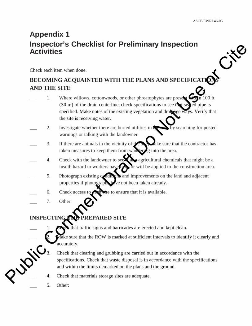
ASCE/EWRI 46-05
Appendix 1 Inspector’s Checklist for Preliminary Inspection Activities
Check each item when done.
BECOMING ACQUAINTED WITH THE PLANS AND SPECIFICATIONS AND THE SITE
___ 1. Where willows, cottonwoods, or other phreatophytes are present within 100 ft (30 m) of the drain centerline, check specifications to see that sealed pipe is specified. Make notes of the existing vegetation and drainage ways. Verify that the site is receiving water.
___ 2. Investigate whether there are buried utilities in the area by searching for posted warnings or talking with the landowner.
___ 3. If there are animals in the vicinity of the site, make sure that the contractor has taken measures to keep them from wandering into the area.
___ 4. Check with the landowner to see if any agricultural chemicals that might be a health hazard to workers have been or will be applied to the construction area.
___ 5. Photograph existing conditions and improvements on the land and adjacent properties if photographs have not been taken already.
___ 6. Check access to each site to ensure that it is available.
___ 7. Other:
INSPECTING THE PREPARED SITE
___ 1. Check that traffic signs and barricades are erected and kept clean.
___ 2. Make sure that the ROW is marked at sufficient intervals to identify it clearly and accurately.
___ 3. Check that clearing and grubbing are carried out in accordance with the specifications. Check that waste disposal is in accordance with the specifications and within the limits demarked on the plans and the ground.
___ 4. Check that materials storage sites are adequate.
___ 5. Other: Public
Com
ment D
raft D
o Not
Use or
Cite

ASCE/EWRI 46-05
INSPECTING EQUIPMENT
___ 1. Find out what equipment will be used on the project, and review inspection procedures for that equipment if necessary.
___ 2. Check contractor’s equipment to ensure compliance with the Reclamation Safety and Health Standards (U.S. Department of the Interior, Bureau of Reclamation 2009b), reference, and specifications requirements.
___ 3. Check fuel storage provisions.
___ 4. Check that available equipment is adequate to do the job. If it is not, discuss it with the contractor. However, equipment choice is the contractor’s responsibility except as limited by plans and specifications.
___ 5. Other:
INSPECTING MATERIALS
___ 1. If materials are to be stored for any length of time, check for proper storage techniques.
___ 2. Reinspect stored materials prior to use to make sure that they are still acceptable.
___ 3. Other:
Corrugated Plastic Pipe
___ 1. Make sure that the lot number is on the list of tested and approved pipe.
___ 2. Look for and reject any damaged sections.
___ 3. Make sure that perforations are cut cleanly and properly located and sized.
___ 4. Check that proper couplings are furnished. Ensure that the couplings meet the water-tightness specification. If welded, inspect all welds to ensure they meet specifications.
___ 5. Visually inspect pipe for defects.
___ 6. Other:
Rigid Plastic Pipe
___ 1. See that the pipe is certified properly. Pub
lic C
ommen
t Draf
t Do N
ot Use
or C
ite

ASCE/EWRI 46-05
___ 2. Look for and reject any damaged sections.
___ 3. If perforated, check the hole spacing and diameter, and make sure that perforations are cut cleanly.
___ 4. Check the pipe diameter against the specifications to determine whether it should be perforated.
___ 5. Other:
Clay and Concrete Pipe
___ 1. Find manufacturer’s markings, and make sure that the joint and pipe types have been approved.
___ 2. Look for and reject any damaged sections or those with manufacturer’s defects.
___ 3. Check the spacing and alignment lugs, if any.
___ 4. Examine the roundness of the pipe to make sure it is not elliptical.
___ 5. Other:
Corrugated Metal Pipe (CMP)
___ 1. Make sure that the size, gauge, and coating (if any) are those called for in the specifications.
___ 2. If coating is required by the specifications, check the integrity of the coating. (The contractor must repair damaged surfaces.)
___ 3. If the specifications call for reformed ends for helical CMP, check to see that it is so furnished.
___ 4. Check for proper couplers.
___ 5. Other:
Manholes
___ 1. Make sure that the pipe and bases are the correct size and have been plant inspected. Inspect all penetrations and grout or boot installations.
___ 2. Visually inspect the pipe and bases for damage, including hairline cracks. Ensure that the precast holes for drainpipes are at the correct location and elevation.
___ 3. Examine lids closely for signs of improper curing, cracking, or damage. Pub
lic C
ommen
t Draf
t Do N
ot Use
or C
ite
ASCE/EWRI 46-05
___ 4. Make sure that the lifting eyes and handles meet specifications and are functional.
___ 5. Other:
Gravel Envelope Material
___ 1. Look for and reject any gravel contaminated by vegetation or surface soils.
___ 2. Watch for “segregation” (sorting of the gravel by size because of improper handling).
___ 3. Other:
PROJECT SAFETY
___ 1. Make daily checks of the contractor’s equipment and construction techniques to ensure compliance with the Reclamation Safety and Health Standards (U.S. Department of the Interior, Bureau of Reclamation 2009b).
___ 2. Watch for workers who are not wearing required protective clothing, and inform the contractor’s representative of such occurrences.
___ 3. Attend the contractor’s weekly safety meetings, and submit a copy of the safety meeting report. The inspector should not provide safety guidance to the contractor.
___ 4. Ensure that vehicle parking does not cause safety hazards by restricting visibility.
___ 5. Other:
Public
Com
ment D
raft D
o Not
Use or
Cite
ASCE/EWRI 46-05
APPENDIX 2
Inspector’s Checklist for Construction Procedures
Check each item when completed.
EXCAVATION
___ 1. Frequently monitor the grade and alignment of the excavation.
___ 2. Consult and follow the guidelines for dust abatement procedures in the Reclamation Safety and Health Standards (U.S. Department of the Interior, Bureau of Reclamation 2009b) and the project specifications.
___ 3. Make sure that excavated materials are placed and retained at least 3 ft (1 m) from the edge of the excavation or as required by the OSHA standards.
___ 4. Overexcavate and stabilize in areas of unstable subgrade. Notify the engineer, and document fully in the daily and special reports.
___ 5. Other:
Classified Excavation
___ 1. Classify rock excavation with the contractor’s representative.
___ 2. Keep complete records of the amount of rock excavated.
___ 3. Other:
Separated Excavation
___ 1. Ascertain whether a plan for separated excavation has been submitted by the contractor and approved by the contracting officer.
___ 2. Make sure that topsoil is separated to the proper depth and width and stockpiled to ensure clean separation of materials.
___ 3. If it appears that separated excavation will be needed (or not needed) for certain reaches of the drain line, discuss the matter with the supervisor before processing.
___ 4. Other:
TRENCHING Pub
lic C
ommen
t Draf
t Do N
ot Use
or C
ite

ASCE/EWRI 46-05
___ 1. Watch for underground utilities not shown on plans or marked in the field by utility companies.
___ 2. If personnel are going to enter a trench that is more than 5 ft (1.5 m) deep, special precautions must be taken if the soil is not hard, dry, or dense, and stable enough so that there is no possibility of movement or cave-in. Be sure that the trench walls are sloped to the angle of repose or flatter, or that an engineered shoring system is installed.
___ 3. See that barricades, fences, and other safeguards are installed where needed to prevent accidental entry of persons or equipment into the trench.
___ 4. Make sure that escape ladders are placed within 25 ft (7.6 m) of workers in the trench, as required by the Reclamation Safety and Health Standards manual (U.S. Department of the Interior, Bureau of Reclamation 2009b).
___ 5. Using the Reclamation Safety and Health Standards Section 22, (U.S. Department of the Interior, Bureau of Reclamation 2009b), determine if shields are needed in the trench. If so, shields must be large enough to accommodate the pipe plus the required thickness of envelope material.
___ 6. Check the health certifications of all hoisting equipment operators employed by the contractor.
___ 7. Record soil types that are different from those shown in the specifications.
___ 8. Other:
LAYING THE PIPE
___ 1. Make sure that a surveyor’s level or other appropriate instrument is set up for checking grade whenever pipe is being laid, and monitor grade frequently during pipe installation.
___ 2. Verify that the grade is being checked frequently after the trencher has passed.
___ 3. Check for pulled joints if a shield is being used on an open joint pipe.
___ 4. If openings are provided on only one side, make sure that they are placed in the specified orientation.
___ 5. Other:
Gravel Envelope Public
Com
ment D
raft D
o Not
Use or
Cite

ASCE/EWRI 46-05
___ 1. Verify that gravel envelope material meets gradation requirements.
___ 2. Check for proper gravel envelope dimensions.
___ 3. Watch for contamination of gravel with soil or organic matter before being placed in the trencher hopper.
___ 4. Check gravel feed in the trenching machine hoppers and the gravel cover over pipe to ensure adequate coverage per specifications.
___ 5. Other:
Corrugated Plastic Tubing
___ 1. Conduct stretch tests at least once a shift, or more often on hot days, or when the contractor’s equipment is having trouble with the operation.
___ 2. Note percentage of stretch and stationing of the test on daily inspection report.
___ 3. Check that couplings are made properly.
___ 4. Verify that the pipe is the specified size.
___ 5. Other:
Other Pipe
___ 1. Make sure that the pipe is the specified diameter.
___ 2. Check that the bell or groove end is uphill.
___ 3. If it is sealed pipe, check the seals. For gasket joints, check that the gasket is properly seated and has not been distorted.
___ 4. Inspect the openings between pipe lengths. Specifications usually call for openings to be 1/8 in. (34 mm) wide, plus or minus 1/16 in. (17 mm).
___ 5. Other:
Corrugated Metal Pipe
___ 1. Check for proper size and gauge.
___ 2. Make sure that the outside of laps are placed upstream.
___ 3. Check for proper couplers.
___ 4. Visually inspect for seam rupture. Pub
lic C
ommen
t Draf
t Do N
ot Use
or C
ite

ASCE/EWRI 46-05
___ 5. Inspect the integrity of coatings, which may become damaged during installation.
___ 6. Other:
MANHOLES
___ 1. Make sure that a surveyor’s level is set up for checking grade whenever a manhole is being set, and monitor grade frequently during the construction process.
___ 2. Check for correct grade, plumb, and alignment.
___ 3. Ensure proper location and size of drainpipe inlet holes.
___ 4. Inspect the proper placement of filter gravel under inlet and outlet.
___ 5. Inspect the connection of drainpipes into the manhole, noting
___ a. Grade
___ b. Length of pipe inside manhole
___ c. Length of pipe of the first joint [18 in. (450 mm) minimum for concrete or tile]
___ d. Satisfactory joint outside of manhole, tongue and groove, clips, and mortar
___ 6. Make sure that, if called for, the gravel envelope is continuous around the lower part of the manhole.
___ 7. Check that the manhole is free of silt deposits.
___ 8. Oversee the backfilling and placement of the cover.
___ 9. Check the rim of the manhole for finish grade.
___ 10. Recheck the grade of the manhole after backfilling.
___ 11. Other:
OUTLETS
___ 1. Make sure that the outlet pipe is the proper gauge, is coated pipe, is specified, and has proper riprap protection.
___ 2. Check that the outlet end of the pipe is at the location and grade shown in the specifications.
Public
Com
ment D
raft D
o Not
Use or
Cite

ASCE/EWRI 46-05
___ 3. Make sure that earth backfill is compacted around the pipe over its full length and for a minimum of 1 ft (300 mm) above the pipe. More may be required. check the specifications.
___ 4. Other:
JACKED CROSSINGS
___ 1. Prior to commencement of jacking operations
___ a. Make sure that the contractor has notified the proper authorities that the crossing will take place and that adequate signs and barricades are installed.
___ b. If special pipe is required by the plans and specifications, be sure that the pipe on hand meets these requirements.
___ c. Review the part of the contractor’s safety program regarding jacking.
___ d. Make sure that all equipment has been safety checked.
___ e. Note any overhead or buried utilities.
___ 2. During the operation
___ a. Make sure that the jacking pits are constructed safely and that there are adequate access and escape routes for workers.
___ b. Check that the jacking equipment is set to proper grade and alignment.
___ c. Make sure that the pipe joints are mated properly.
___ d. Check that jacked pipe remains on grade.
___ e. Make sure that the boring or excavation does not get too far ahead of the jacked pipe. Check specifications for requirements.
___ f. Determine the grade of the pipe. Special cradles may be required if the grade has varied.
___ g. Verify that any special backfill requirements required by the owner are satisfied.
___ 3. After the operation
___ a. Check and record pipe grade at both ends.
___ b. Make sure that the jacking pits are backfilled and compacted properly.
___ c. Oversee the restoration of the ground surface to its original condition where practical.
Public
Com
ment D
raft D
o Not
Use or
Cite

ASCE/EWRI 46-05
___ d. Note any site damage.
___ 4. Other:
BACKFILLING
___ 1. Ensure that proper procedure is followed to prevent displacement of the pipe.
___ 2. See that no organic matter, large rocks, or ice are placed within the specified distance from the pipe.
___ 3. Check for clean separation in areas of separated excavation.
___ 4. Be sure that no compacting takes place except where specified.
___ 5. Make sure that backfilling occurs within the specified period of time and distance behind the trenching operation.
___ 6. Check that site restoration takes place on time.
___ 7. Record any site damage.
___ 8. Report measurements of damaged road surfacing.
___ 9. Other:
REPAIR OF DAMAGED SECTIONS
___ 1. Check use of safety equipment and procedures, since soils may be unstable and cave-ins could occur. CAVE-INS KILL PEOPLE.
___ 2. Inspect reestablishing of grade and alignment after repairs are made.
___ 3. Make sure that the gravel envelope is replaced, clean, and in the specified thickness.
___ 4. Retest pipe after backfilling has been completed.
___ 5. Document all pertinent details of the repair procedure.
___ 6. Other:
TESTING (Applicable for Certain Types of Pipe)
___ 1. The test device must be pulled through the installed pipe after backfilling has been completed.
___ 2. Mark ball and be sure that it cannot be retrieved from upper end of pipe. Pub
lic C
ommen
t Draf
t Do N
ot Use
or C
ite

ASCE/EWRI 46-05
___ 3. Observe and identify ball after it is recovered from downstream manhole or outlet.
___ 4. Make sure that excessive force is not used to flush the ball (or pull the plug).
___ 5. Note any unusual occurrences.
___ 6. Other:
SITE RESTORATION
___ 1. Oversee surface debris and rock pickup.
___ 2. Make sure that any required mound is placed over the pipe trench.
___ 3. Inspect cleanliness of manholes, and ensure that silt is removed if necessary.
___ 4. Check the contractor’s restoration of roads and fences on the ROW and on haul routes.
___ 5. Other:
Public
Com
ment D
raft D
o Not
Use or
Cite

Standard ASCE/EWRI 47-XX / DRAFT 1
A S C E S TANDA R D ASCE/EWRI 47-XX
American Society of Civil Engineers Standard Guidelines for the Operation and Maintenance of Urban Stormwater Systems
Public
Com
ment D
raft D
o Not
Use or
Cite

Standard ASCE/EWRI 47-XX / DRAFT 2
CONTENTS
Foreword ....................................................................................................................................
Acknowledgments..............................................................................................................................
1.0 Scope
2.0 Definitions
3.0 Operations and Maintenance Plan ........................................................................................
3.1 Scope ........................................................................................................................
3.2 Responsibilities .........................................................................................................
3.3 Design Criteria ..........................................................................................................
3.4 Scheduled Procedures ...............................................................................................
3.5 Unscheduled Operating Procedures ..........................................................................
3.5.1 Line Blockage ...............................................................................................
3.5.2 Control Structure Blockage ...........................................................................
3.5.3 Manholes and Catch Basin Blockage ...........................................................
3.5.4 Other Urban Stormwater System Components .............................................
3.6 Preventive Maintenance ............................................................................................
3.6.1 Checklists ......................................................................................................
3.6.2 Annual System Inspections ...........................................................................
3.7 Safety
3.7.1 Structures . .....................................................................................................
3.7.2 Mechanical ....................................................................................................
3.7.3 Electrical .......................................................................................................
3.7.4 Underground Procedures ..............................................................................
3.7.5 Other Safety Considerations
4.0 Water Quality
4.1 Environmental Indicators ..........................................................................................
4.2 Water Quality Standards
Public
Com
ment D
raft D
o Not
Use or
Cite
Standard ASCE/EWRI 47-XX / DRAFT 3
5.0 Periodic Inspection ................................................................................................................
5.1 Underground Safety ..................................................................................................
5.2 Inspection ..................................................................................................................
5.2.1 Closed Conduits ............................................................................................
5.2.2 Open Channels ..............................................................................................
5.2.3 Manholes and Confluence Structures ...........................................................
5.2.4 Catch Basins ..................................................................................................
5.2.5 Retention/Detention Ponds ...........................................................................
5.2.6 Major Structures ............................................................................................
5.2.7 Flapgates .......................................................................................................
5.2.8 Pump Stations ...............................................................................................
6.0 Maintenance
6.1 Cleaning ....................................................................................................................
6.2 Electrical ...................................................................................................................
6.3 Mechanical ................................................................................................................
6.4 Repair
6.5 Rehabilitation ............................................................................................................
6.6 Safety
7.0 Applicable Documents/References .......................................................................................
Index
Public
Com
ment D
raft D
o Not
Use or
Cite

Standard ASCE/EWRI 47-XX / DRAFT 4
FOREWORD
The Board of Direction approved revisions to the ASCE Rules for Standards Committees to
govern the writing and maintenance of standards developed by ASCE. All such standards are
developed by a consensus standards process managed by the ASCE Codes and Standards
Committee (CSC). The consensus process includes balloting by a balanced standards committee,
and reviewing during a public comment period. All standards are updated or reaffirmed by the
same process at intervals between five and 10 years. Requests for formal interpretations shall be
processed in accordance with Section 7 of ASCE Rules for Standards Committees, which are
available at www.asce.org. Errata, addenda, supplements, and interpretations, if any, for these
standard guidelines also can be found at www.asce.org.
The Standard Guidelines for the Operation and Maintenance of Urban Stormwater Systems is a
companion to the Standard Guidelines for the Design of Urban Stormwater Systems and
Standard Guidelines for the Installation of Urban Stormwater Systems. These standard
guidelines were developed by the Urban Drainage Standards Committee, which is responsible to
the Environmental and Water Resources Institute of the American Society of Civil Engineers.
The provisions of this document are written in permissive language and, as such, offer to the user
a series of options or instructions but do not prescribe a specific course of action. Significant
judgment is left to the user of this document.
These standard guidelines may involve hazardous materials, operations, and equipment. These
standard guidelines do not purport to address the safety problems associated with its application.
It is the responsibility of whoever uses these standard guidelines to establish appropriate safety
and health practices and to determine the applicability of regulatory and nonregulatory
limitations.
These standard guidelines have been prepared in accordance with recognized engineering
principles and should not be used without the user’s competent knowledge for a specific
application. The publication of these standard guidelines by ASCE is not intended to warrant that
the information contained therein is suitable for any general or specific use, and ASCE takes no Public
Com
ment D
raft D
o Not
Use or
Cite

Standard ASCE/EWRI 47-XX / DRAFT 5
position respecting the validity of patent rights. The user is advised that the determination of
patent rights or risk of infringement is entirely his or her own responsibility.
Public
Com
ment D
raft D
o Not
Use or
Cite

Standard ASCE/EWRI 47-XX / DRAFT 6
ACKNOWLEDGMENTS
The American Society of Civil Engineers (ASCE) acknowledges the work of the Urban Drainage
Standards Committee of the Environmental and Water Resources Institute of ASCE (EWRI of
ASCE).
This group comprises individuals from many backgrounds, including consulting engineering,
research, construction industry, education, and government. Those individuals who serve on the
Urban Drainage Standards Committee are
William Curtis Archdeacon, P.E., R.L.S., Past Chair
Kathlie Jeng-Bulloch, Ph.D., P.E., D.WRE, CFM, M.ASCE, Chair
William P. Bulloch, P.E., M.ASCE
Christopher B. Burke, Ph.D., P.E., D.WRE, F.ASCE
James C.-I. Chang, Ph.D., P.E.
Richard Field, P.E., D.WRE, BCEE, M.ASCE
Jeffrey S. Glenn, P.E., D.WRE, CFM, F.ASCE
Robert S. Giurato
S. David Graber, P.E., F.ASCE, Vice Chair & Corresp.Editor
Jay M. Herskowitz, P.E., M.ASCE
Conrad G. Keyes, Jr., Ph.D., P.E., L.S., D.WRE, Dist.M.ASCE
James H. Lenhart, Jr., P.E., D.WRE, M.ASCE
Lawrence M. Magura, P.E., M.ASCE, Secretary
Garvin J. Pederson, P.E., M.ASCE
Anthony N. Tafuri, P.E., D.WRE, M.ASCE
Kenneth E. Waite, P.E., M.ASCE
Keh-Han Wang, Ph.D., M.ASCE Pub
lic C
ommen
t Draf
t Do N
ot Use
or C
ite

Standard ASCE/EWRI 47-XX / DRAFT 7
William J. Weaver, P.E., M.ASCE
Donald E. Woodward, P.E., F.ASCE
The corresponding editor recognizes the following committee members who were particularly
helpful in updating the standard guidelines: Jeffrey S. Glenn, Conrad G. Keyes, Jr., James H.
Lenhart, Kenneth E. Waite, William J. Weaver, and Donald E. Woodward.
Public
Com
ment D
raft D
o Not
Use or
Cite

Standard ASCE/EWRI 47-XX / DRAFT 8
Chapter 1
SCOPE
The intent of this standard is to present operation and maintenance guidance for urban
stormwater systems. It updates ASCE/EWRI 47-05 Standard Guidelines for the Operation and
Maintenance of Urban Stormwater Systems with material developed within the past eight years.
The collection and conveyance of urban drainage waters is within the purview of these standard
guidelines for applications such as airports; roads and other transportation systems; and
industrial, commercial, residential, and recreation areas. Incidental subsurface drainage water is
also considered. This document is intended for guidance for the operation and maintenance phase
of urban stormwater systems.
Some of the applications these standard guidelines do not address include agricultural drainage,
landfills drainage, sanitary sewers, combined sewers, and groundwater recharge systems.
Public
Com
ment D
raft D
o Not
Use or
Cite

Standard ASCE/EWRI 47-XX / DRAFT 9
Chapter 2
DEFINITIONS
This section defines specific terms for use in these guidelines. The reference documents listed in
11.0 of ASCE/EWRI 45 also may be helpful in understanding the terms in this document.
Aquatic Vegetation—Vegetation that grows in water or water-saturated soils.
Benching—Excavation of trench walls in a stair-step pattern to prevent cave-ins.
Blockages—Obstructions in drainage pipes or open channels.
BOD—Biochemical Oxygen Demand, the amount of dissolved oxygen, measured in milligrams
per liter (mg/L), required by microorganisms in the chemical breakdown of organic
matter, in a specified amount of time.
Colorimetric Devices—Instruments used to measure the concentration of a known solution
constituent by comparison with colors of standard solution of that constituent.
Control Structure—Any structure designed and intended to control or modify the flow velocity,
quantity, or direction of stormwater through or over the structure.
DO—Dissolved oxygen in water measured in milligrams per liter (mg/L).
Detention Pond—An artificial or natural storage and flow-control facility that is used to
attenuate stormwater flow. It stores stormwater after a storm and discharges at a
controlled rate to a downstream water body. It may be a dry pond or a wet pond with
some water remaining between runoff events.
Duckbill Valve—A rubber valve used to prevent backflow.
Flapgate—A hinged cover on the end of a drainage pipe. It is intended to prevent surface water
and debris from entering the pipe during high-flow events in the receiving stream.
Hydraulic Flushing—Use of hydraulic heads greater than normal operating conditions to clear
minor blockages in pipe drains.
Jetting—High-pressure water method used to clean pipes.
NH3—Ammonia gas dissolved in water.
Organic N—Organically bound form of nitrogen that is the most reduced form (-3 oxidation
state). Organic nitrogen includes all nitrogenous organic compounds, such as proteins,
polypeptides, amino acids, and urea (H2NCONH2). Pub
lic C
ommen
t Draf
t Do N
ot Use
or C
ite

Standard ASCE/EWRI 47-XX / DRAFT 10
OSHA—Occupational Safety and Health Administration, the U.S, federal agency responsible for
safety and health concerns on construction jobsites and in the workplace.
Preventive Maintenance—Maintenance activity intended to prevent unnecessary wear and
maintenance breakdown of equipment or facilities.
Record Drawings—Drawings prepared during or after construction showing the final
measurements of the actual construction, including any deviations from the design
drawings and certain other field observations, such as tie-in locations.
Restricted Capacity—Partial blockage or obstruction in a drainage facility, such that the facility
cannot pass the design flow.
Retention Pond—Water-holding facility that has no positive outlet and is designed to capture
and retain a volume of runoff and reduce the water volume only by means of infiltration,
evaporation, or evapotranspiration or a combination of these.
Rodding—Mechanical method used to clean pipes.
Shoring—Bracing of vertical trench walls to prevent cave-ins.
Sloping—Excavation of trench walls to a stable angle to prevent cave-ins.
Spalling—Breaking of chips or flakes from concrete, rock, or iron surfaces.
Storm Drains—Drainage pipes or open channels intended solely to transport stormwater.
Surcharging—Introduction of water to the drainage system in quantities that create abnormally
high hydraulic heads.
Public
Com
ment D
raft D
o Not
Use or
Cite

Standard ASCE/EWRI 47-XX / DRAFT 11
Chapter 3
OPERATION AND MAINTENANCE PLAN
This section is a generalized format of what should be included in an operation and maintenance
plan (O&MP). It may be necessary to modify this plan to reflect more accurately the specific
drainage system under consideration. This is intended as the general standard guidelines for
preparing procedures and timetables related to routine operation and maintenance of urban
stormwater systems after construction. Technical personnel should be familiar with the basic
concepts of surface drainage facilities.
Operation and maintenance instruction materials submitted by manufacturers supplying
equipment for the urban stormwater systems components should be retained and incorporated
into the procedures document as needed. The manual should explain the general operational
relationships among the various system components of the facility and include any
manufacturers’ instructions or recommendations. Adherence to these procedures is essential to
retain the operating capacity of a facility throughout its expected service life.
3.1 SCOPE
Urban stormwater systems typically are complex integrated systems having features such as
drains, sewers, detention/retention facilities, pump stations, control structures, and water quality
protection/enhancement facilities. All such features of the system should be considered in the
O&MP for urban stormwater systems.
3.2 RESPONSIBILITIES
Development and implementation of the O&MP is the responsibility of the owner. The O&MP
should address safety to the public, safety of operating personnel, investment protection,
operational readiness, emergency contingency plans, and legal aspects of operating and
maintaining the urban stormwater system.
Public
Com
ment D
raft D
o Not
Use or
Cite

Standard ASCE/EWRI 47-XX / DRAFT 12
3.3 DESIGN CRITERIA
The O&MP should reflect the original design criteria in terms of capacity, maximum and
minimum flow velocities, materials, detention/retention times, primary and alternate power
sources, emergency overflows, and redundancy. It may not always be possible or desirable to
reproduce the original design criteria, but that is always the point of beginning. If the O&MP
correctly reflects the original design criteria, appropriate modifications can be made from an
informed position.
The location of the record drawings and final design report should be included in this section.
These are the official records of how the urban stormwater system was constructed and should be
operated. The original documents should be kept in a safe location. As future development takes
place and the stormwater system is expanded, an amended O&MP should be completed to
include the newer system.
3.4 SCHEDULED PROCEDURES
Normal operating procedures are those scheduled, routine activities that are required to keep the
urban stormwater system in good operating condition. They include but are not limited to
• Periodic inspection of system components
• Cleaning system components of silt, grit, and floatable debris
• Repair of minor damage caused by flooding, accidents, and vandalism
• Preventive maintenance on mechanical and electrical components
• Landscape maintenance including control and management of vegetation (i.e.,
mowing of grasslands)
• Chemical applications
• Adjustment to changing land use patterns.
Public
Com
ment D
raft D
o Not
Use or
Cite

Standard ASCE/EWRI 47-XX / DRAFT 13
3.5 UNSCHEDULED OPERATING PROCEDURES
The unscheduled operating procedures that should be included in the O&MP are line and control
structure blockage, failure hazard, manhole and catch basin blockage, and reduced performance
of other urban stormwater system components.
3.5.1 Line Blockage
If a pipeline becomes blocked, rodding or jetting may be required to clear it. Care should be
taken to avoid damaging the pipe. During cleaning operations, a careful watch should be
maintained at the downstream manhole for an indication of the cause of the blockage.
Cleanout assemblies and manholes may be located at periodic intervals along the pipeline as
shown on the record drawings. If a conveyance main becomes blocked, the nearest of these
cleanouts or manholes can be located and accessed, and cleaning equipment inserted.
Hydraulic flushing may be attempted to clear any pipeline. However, special care should be
taken to avoid damage caused by surcharging. For large-diameter pipe, or conduits, other types
of maintenance equipment may be needed to remove blockages.
Large-diameter conduit stormwater systems often are constructed on flat grades and therefore are
subject to deposits of sediment and debris. If a blockage occurs in these large conduits,
mechanical equipment most likely will be required to remove the material. Maintenance
personnel should review design documents and request access shafts large enough to permit
entrance of the proper equipment for cleaning the conduit.
The blockage material should be evaluated to identify possible remedial steps to minimize
recurrence.
3.5.2 Control Structure Blockage
Floating debris during storm events may restrict control structures. They should be inspected
after each significant event and cleaned as necessary to restore them to original capacity. In arid
climates where storm flows are infrequent, control structures should be checked and cleaned at
regular intervals of six to 12 months, depending on the local conditions. Public
Com
ment D
raft D
o Not
Use or
Cite

Standard ASCE/EWRI 47-XX / DRAFT 14
Each time the structure is cleaned, any structural damage should be noted and scheduled for
repair. Some spalling, cracking, and chipping of concrete should be expected and may not be
extensive enough to be considered as structural damage. Generally, if reinforcing steel is
exposed to corrosion or if displacement has occurred because of cracking, the structure should be
repaired.
If the control structure impounds enough water to pose a hazard to human life in the event of
failure, a licensed engineer should be consulted to determine whether structural damage has
occurred.
3.5.3 Manholes and Catch Basin Blockage
Blockages may cause local flooding and possibly damage to other components of the urban
stormwater system. These blockages should be removed as expeditiously as can be done within
reason. If the blockage must be removed while the storm event is in progress, it may be
necessary to evacuate the structure by pumping. In such cases, the capacity of the pump should
exceed the inflow to the structure, and a suitable bypass or disposal route should be established.
The O&MP should address these contingencies.
3.5.4 Other Urban Stormwater System Components
In the event of reduced performance of urban stormwater system components, the correction
procedures set forth in the owner’s O&MP should comply with manufacturers’ recommendations
if applicable.
3.6 PREVENTIVE MAINTENANCE PROCEDURES
Maintenance can be classified broadly as either corrective or preventive. Corrective maintenance
involves the repair of equipment after breakdown or failure to function. Equipment breakdown
usually is related to a failure of preventive maintenance. As the term implies, preventive
maintenance is intended to prevent disruptive breakdowns. Because many components of the
urban stormwater system that require different preventive maintenance actions at different time
intervals may be involved, preventive maintenance is performed best on a scheduled basis from a
checklist. Public
Com
ment D
raft D
o Not
Use or
Cite

Standard ASCE/EWRI 47-XX / DRAFT 15
3.6.1 Checklists
Checklists should be maintained for each component of the urban stormwater system with
recommended schedules for inspection clearly stated. Checklists should include each aspect of
the inspection such as damage to structure, evidence of restricted capacity, manufacturers’
recommended maintenance, and so on. A current copy of each checklist should be placed in an
appropriate location. Once all inspections outlined on the form have been completed, the form
should be replaced and the completed forms filed with the owners’ records.
3.6.2 Annual System Inspections
A general overview inspection of the entire system should be performed at least annually in
addition to the more intensive inspections performed as discussed in 5.0 of these standard
guidelines. Local conditions may make more frequent inspections of certain components
necessary. These may be adjusted as experience is gained in the operation of the system but in no
circumstances should the annual inspection be extended.
3.7 SAFETY
All personnel are responsible for keeping areas safe and clean. Guards should be in place on
operating equipment and all areas should be properly lighted. All enclosed space should be
adequately ventilated prior to personnel entering. All personnel should be sure they understand
the following:
• Location of all safety equipment
• Use of safety equipment and devices
• All safety rules for the location
• Need to be especially alert in “danger” areas
3.7.1 Structures
The primary safety concerns for structures are enclosed spaces, ladders, and slipping and falling.
Oxygen-deficient air and toxic gases are of particular concern in enclosed spaces associated with
storm drains. OSHA regulations 29CFR1910.146 for confined spaces and 29CFR1910.25, 26,
and 27 for ladders, or similar, should be adopted and followed.
Public
Com
ment D
raft D
o Not
Use or
Cite

Standard ASCE/EWRI 47-XX / DRAFT 16
3.7.2 Mechanical
Items that should be included under the mechanical equipment safety section are as follows:
• When working on pumps, be sure suction and discharge valves are fully closed.
• Maintenance on equipment in operation should be limited to lubrication, packing
adjustments, minor repair, or as allowed by the manufacturers’ instructions.
3.7.3 Electrical
Items that should be included under the electrical equipment safety section are as follows:
• Lock out and tag main switch of electrical equipment before working on it.
• Do not remove tag without first checking with person who initiated the tag.
• Report and log any unusual motor temperature, noise, vibration, and so on.
3.7.4 Underground Procedures
Where excavation of underground facilities is undertaken, OSHA-approved trenching procedures
must be followed in the United States. Sloping or shoring requirements vary with local geologic
and soil conditions. Requirements for sloping, benching, and shoring are found in OSHA
regulation 29 CFR 1926.652, Appendices A, B, C, and D. When excavating, the operators should
be alert to both overhead power lines and underground utilities that pose a hazard to excavation
equipment or personnel. Buried gas and electric lines pose the greatest hazard to operators, but
accidents involving communication lines, water lines, and other utilities can be very costly to
those causing the damage. Telephone numbers for all underground utility locators should be
included in the O&MP.
3.7.5 Other Safety Considerations
Workers entering structures during high-flow conditions or in areas of potential flash flooding
should be protected by safety lines, floatation devices, and lighting. System features and signage
designed to provide public safety should be kept in good condition. For further information, refer
to OSHA safety requirements for workers in confined spaces.
Public
Com
ment D
raft D
o Not
Use or
Cite
Standard ASCE/EWRI 47-XX / DRAFT 17
Chapter 4
WATER QUALITY
Studies have shown that a large percentage of pollutants often occur during the first flush of a
stormwater event and from either highly erodible or highly impervious areas. Also, it has been
proven that urban stormwater systems that incorporate sedimentation and infiltration provide an
effective means of improving water quality. Therefore, from an operation and maintenance
perspective, water quality should be dealt with at the originating source and at the control device.
Limitations may be imposed on the discharge based on the receiving waters. Water quality
standards limit the concentration of various parameters to be discharged. Standards generally are
established by federal, state, or local governments and are subject to continual revisions. These
standards can be used as a basis for evaluating water quality. The suggested list of parameters for
analysis include, as a minimum: temperature, color, odor, pH, dissolved oxygen, total suspended
solids, and turbidity. Considerations include inorganic chemicals, heavy metals, corrosiveness,
organic chemicals (pesticides/herbicides), and microbiological and radioactive materials.
Sampling points and frequency can be determined best in the field. Sampling points should be
located at strategic points throughout the system.
An important reference on water quality standards is American Society of Civil Engineers
(ASCE) 33-09, Comprehensive Transboundary Water Quality Management Agreement.
A broad-based discussion of maintenance factors important to water quality is provided in
Lenhart and Harbaugh (2000).
4.1 ENVIRONMENTAL INDICATORS
An adequate field inspection program is essential for identifying potentially adverse water
quality impacts. The most obvious pollution sources are ongoing construction activities where
sediment transport is a major concern. Steps should be taken to ensure that proposed erosion and
sediment control measures are installed and function as designed until final stabilization of the
site is achieved. Measures also should be in place to address off-site sediment discharges when Pub
lic C
ommen
t Draf
t Do N
ot Use
or C
ite
Standard ASCE/EWRI 47-XX / DRAFT 18
they occur. Unfortunately, many pollutants, such as leakage from motor vehicles and lawn care
products, are more difficult to address. Urban stormwater system managers should use
innovative design, public education programs, and other indirect methods to control nonpoint
sources of stormwater pollution.
For other, less obvious sources of pollutants, such as developed residential, commercial, and
industrial areas within the watershed, an inspection program that includes a dry weather
monitoring element to detect illicit connections or illegal dumping to the urban stormwater
system would be beneficial. Observed dry weather flows could be tested initially with
colorimetric devices to identify problem constituents and locate their sources. If concentrations
warrant it, more detailed test methods can be employed to characterize the pollutants of concern
further.
Periodic inspection of water quality control devices within the urban stormwater system provides
for improved operation and identifies needed maintenance. Indicators of possible water quality
impairment include the following:
• Growth of algae and larger aquatic vegetation, such as grass, and weeds
• Fish kills and nuisance odors
• Debris, sediment accumulation, or heavy turbidity
• Condition of hydraulic facilities such as pipes, channels, and outlet control devices
• Oil sheens and other floatables
4.2 WATER QUALITY STANDARDS
Water quality standards, where instituted, should be based on a specific environmental quality
objective as determined by the intended use of the receiving waters. Beneficial uses include
• Water supply—municipal and industrial
• Recreational—swimming, boating, and aesthetics
• Fisheries—commercial and sport
• Ecological balance. Water quality problems that affect desired uses include
Public
Com
ment D
raft D
o Not
Use or
Cite

Standard ASCE/EWRI 47-XX / DRAFT 19
o Low dissolved oxygen (DO)
o High levels of bacteria and other pathogens
o Excessive plant growth (eutrophication)
o High toxic chemical levels
o Oil sheens and other floatables
Water quality variables that may be subject to effluent limitations include but may not be limited
to BOD, total or suspended solids, pH, total petroleum hydrocarbons, NH3, organic N, organic
solids, DO, total and fecal coliform bacteria, fecal streptococci, nitrogen, phosphorus, metals,
pesticides, and herbicides.
Public
Com
ment D
raft D
o Not
Use or
Cite

Standard ASCE/EWRI 47-XX / DRAFT 20
Chapter 5
PERIODIC INSPECTION
The frequency of inspection of an urban stormwater system can vary greatly depending on a
number of factors and conditions. The purpose of the inspection is to determine if the system has
any adverse conditions or blockage problems. If such exist, then maintenance crews can be
dispatched to correct the situation and return the system to peak performance.
One of the major factors in determining the frequency of inspection is how the system was
designed and constructed. If the system was designed to be self-cleaning, then inspections can be
less frequent.
In areas where the system carries heavy sediment loads and the conduits are subject to invert
erosion, inspections may have to occur annually. Areas subject to the storm drain being loaded
with trash by the public also may require frequent inspections.
Experience has indicated that storm drains can be expected to intercept almost anything that can
get into the inlet appurtenances, and maintenance crews should be prepared to clean out a variety
of objects.
5.1 UNDERGROUND SAFETY
All persons inspecting conduits below the ground surface or any other confined space in the
system should take the utmost caution when entering these areas. Deadly gases, such as methane,
can be produced by decaying material within the storm drain, or these gases can seep in from
adjacent sewers or gas lines and be considered suspect even though they have numerous air inlets
to the surface. All storm drains should be considered suspect, even though they have numerous
air vents to the surface, because they can contain deposits of decaying material, which are
notorious for producing deadly gases.
In the United States, all persons entering underground conduits or other confined spaces are
required to conform to OSHA regulation 29CFR1910.146 for entry into confined spaces. All
drain inspectors should wear long-sleeved shirts or jackets, long pants, nonslip shoes, and gloves Pub
lic C
ommen
t Draf
t Do N
ot Use
or C
ite

Standard ASCE/EWRI 47-XX / DRAFT 21
to protect from encounters with insects and spiders, which frequent such places in many
locations. Inspectors also should wear safety harnesses to facilitate quick extraction from the
conduit in the event that the inspector becomes disabled. All inspection personnel should have
adequate safety training to a level of competence commensurate with the complexity of the
system.
5.2 INSPECTION
As indicated earlier, the frequency of inspection depends on a number of factors. The original
cost of the facility and the risk and consequences of failure should be considered when schedules
are determined. The following recommended schedules have worked well on a wide range of
facilities. They provide a starting point that may have to be adjusted to fit specific systems. As
experience is gained with each component of the urban stormwater system, the schedule may be
modified to fit local conditions and risk factors.
Record keeping is important. Complete records of previous inspections provide a gauge for
comparison to determine the rate and severity of deterioration.
5.2.1 Closed Conduits
The schedule for closed conduits should approach the following:
• Complete inspection once every six years. This is a walk-through, inspecting every
aspect of the conduit, such as wear on the invert, integrity of the joints, sediment
deposits, and structural integrity. Conduits that are too small for walking in can be
inspected by a person towed on a dolly. Even smaller conduits may require video
inspection.
• Spot inspection once every three years. Essentially, this is inspecting the conduit from
a manhole. If problems are spotted, a more extensive inspection may be required.
• Conduits subject to extensive invert wear may require annual inspections to be sure
the invert has not eroded beyond a point where repair is necessary.
• Conduits subject to heavy debris flows should be spot-checked annually. These spot
checks may require more inspection if extensive debris deposits are found. Pub
lic C
ommen
t Draf
t Do N
ot Use
or C
ite

Standard ASCE/EWRI 47-XX / DRAFT 22
5.2.2 Open Channels
The schedule for open channels should be as follows:
• Complete inspection every six years. This would be a channel walk-through,
inspecting the invert and channel walls for wear and cracking. Close attention should
be paid to any scouring or undermining of the channel walls or invert. Any settlement
of the channel should be investigated to determine its underlying cause. Also, if the
channel has fencing and access roads, they should be included in the inspection.
• Spot-check every three years. This would be inspecting the channel at street crossings
or other points of access.
• Channels subject to heavy sediment loads that cause invert wear should be inspected
annually.
• Channels carrying large debris loads also may have to be inspected annually at
locations where debris may deposit.
• Inspect system immediately after extreme and unusual flood events or earthquakes.
5.2.3 Manholes and Confluence Structures
Manholes and confluence structures should be included in the six-year complete inspection of
the storm drain. Confluence structures should be inspected for possible damage caused by
floating debris discharging from laterals. The manhole shafts on storm drains, if well-
constructed, are generally trouble-free.
The manhole frame and cover on the surface, however, can be subject to damage depending on
traffic, location, and street maintenance. It is important to check to see that manhole covers have
not been paved over as a result of street maintenance.
5.2.4 Catch Basins
Catch basins, especially those with curb opening inlets, are subject to being used as a trash
depository during dry seasons. In many locations, catch basins should be inspected annually to
determine if cleaning is necessary. A number of organizations use an inspection-cleanout
procedure. A maintenance crew with a vacuum truck should be available to the inspector. This Pub
lic C
ommen
t Draf
t Do N
ot Use
or C
ite

Standard ASCE/EWRI 47-XX / DRAFT 23
has proven to be economical in many areas. An inspection, inspection-cleanout, or both should
occur at least once every three years. Routine maintenance activities, such as grass cutting,
provide opportunities to observe the facility more casually. Inspections may be scheduled if
developing problems are noted. The frequency of inspection-cleanouts should be adjusted for
each stormwater system.
Also inspect the catch basins for mechanical damage. Damage can occur to the grates, cracking
or degradation of the structure or collars, or settling of the structure from traffic impacts. Some
catch basins have inverted elbows that are broken frequently by attempts to unclog them.
In many areas catch basins are equipped with trash exclusion screens that can clog rapidly;
hence, more frequent inspection may be warranted.
5.2.5 Retention/Detention Ponds
Retention/detention ponds may be located on the surface or underground. Because most
retention/detention ponds serve a critical function in the system, they should be spot-checked
annually for problems that could decrease capacity. A complete inspection should be made once
every six years to check the pond and all its appurtenances. More frequent inspections are
necessary if failure of the structure would threaten life and property.
The inspector should observe and note any sinkholes, cracks, or ruptures. Evidence of seepage,
including piping, embankment sloughing, or the presence of detrimental vegetation, should be
noted. Ponds should be examined to determine if sediment deposits are significant enough to
require removal, particularly if groundwater recharge is a joint function of the pond. All
associated valves, controls, venting, and cathodic protection systems should be examined.
Overflow drains should be checked to ensure that flows are directed away from the structure to
prevent undercutting. Concrete ponds should be examined for foundation settlement, wall
displacement, cracking or spalling, deterioration of roof supports, and any sign of leakage.
Inspection is critical for ponds, especially in populated areas that are provided with chain–link
fence or other means of protecting the public and discouraging unauthorized access, as well as
those with emergency escape facilities. The need to safeguard against acts of vandalism should
be considered during the inspection. Pub
lic C
ommen
t Draf
t Do N
ot Use
or C
ite

Standard ASCE/EWRI 47-XX / DRAFT 24
The depth and capacity of the retention or detention structure should be considered along with
the design storm frequency and other factors to assess the relative hazard posed by the structure.
This analysis should govern the frequency and level of detail for both periodic and special
inspections.
Retention/detention structures should be inspected immediately after extreme and unusual flood
events or earthquakes.
5.2.6 Major Structures
All major structures should be inspected immediately after extreme and unusual flood events or
earthquakes in addition to the following:
• Submerged outlets (lake or ocean) should be completely inspected once every six
years. If outlets experience heavy marine growth, they may require more frequent
inspection.
• Inlet-outlet structures should be completely inspected once every six years on the
same schedule as the storm drain or channel. If a particular location has problems
with debris, a more frequent inspection would be required.
• Riprap, gabions, or other fabricated slope control products should be inspected and
repair or replacement scheduled as necessary.
5.2.7 Flapgates and Duckbill Backflow Preventers
Flapgates and duckbill backflow preventers almost always serve a critical function on urban
stormwater drain systems. If they do not operate as intended, flooding probably will occur. An
annual inspection is therefore a good starting point. If experience indicates no problems, the
frequency of inspection can be decreased but not less than once every three years and
immediately after reports of malfunctioning.
5.2.8 Pump Stations
Pump stations on urban stormwater drain systems serve a critical function and should be
inspected annually. Pump stations should be operated during the inspection for a sufficient length
of time to ensure that all components are functioning properly. This includes the following: Public
Com
ment D
raft D
o Not
Use or
Cite

Standard ASCE/EWRI 47-XX / DRAFT 25
• Mechanical equipment
• Electrical equipment
• Fuel tanks and fuel lines
• Wet wells
• Trash racks
• Discharge lines
Public
Com
ment D
raft D
o Not
Use or
Cite

Standard ASCE/EWRI 47-XX / DRAFT 26
Chapter 6
MAINTENANCE
Provisions should be made to ensure the long-term maintenance of stormwater systems. Merely
assigning responsibility for maintenance often is not sufficient; usually the source of funding for
maintenance activities should be specified as well. Funding should be provided for scheduled
and unscheduled or emergency maintenance. A lack of routine preventive maintenance initially
will cause a reduction in the flow-carrying capacity of the system; eventually, this can lead to
conduit instability, which, if ignored, may result in conduit collapse and the complete blockage
of all flows. The O&MP described in 3.0 of these standard guidelines will serve as a guide to
most maintenance activities, whether routine or extraordinary.
6.1 CLEANING
Maintenance is a continuing responsibility, with the objective of retaining the functional
capability of the stormwater conduit and its associated structures to store or convey stormwater
flows in accordance with the original design and intended purpose.
The structures associated with stormwater conduits, while facilitating the conveyance of
stormwater flows, also generally are designed either to restrict the entry of large debris, such as
tree branches or rocks, or to facilitate the removal of finer sediments that could be transported
downstream. When debris removal utilizes large and heavy equipment, care should be taken not
to damage the structure. Structures, such as catch basins, ponds, manholes, and trash racks,
should be cleaned to minimize flow restrictions and prevent undue stress on the structure from
water buildup. The structures may not be designed to withstand the direct loading of heavy
equipment, especially when considerable vibration is associated with the removal process.
Some installations may not provide access for mechanical cleaning. In these installations,
chemical treatment may be necessary. In other installations, chemical treatment in place of or in
conjunction with mechanical cleaning may be the preferred economic alternative. However,
economics should not be the sole criterion. Chemical cleaning should be done in an
environmentally responsible manner considering water quality impacts. Acid solutions should be Pub
lic C
ommen
t Draf
t Do N
ot Use
or C
ite

Standard ASCE/EWRI 47-XX / DRAFT 27
contained and controlled until they are neutralized effectively. Some stormwater conduits and
their associated structures, such as retention ponds, may be cleaned by the use of herbicidal
sprays. These sprays are also chemicals and easily transported via air currents. Only trained and
licensed personnel should apply these sprays.
Cleaning also may include mowing grass in channels, repairing trails, maintaining vegetative
barriers, and cleaning unwanted growth from riprap, to name a few. Each drainage system will
have unique characteristics to challenge maintenance personnel.
The removal of sediment from retention/detention ponds should consider the potential presence
of hazardous waste and sampling needs. Watersheds tributary to urban stormwater systems can
include numerous pollutant sources. Consult with state, local, and federal regulatory agencies
about permit, construction, and disposal requirements prior to implementing a sediment removal
project.
6.2 ELECTRICAL
Pumps and motors that are integral parts of stormwater systems usually will have published
maintenance guidelines provided by the manufacturer. If none are available, the design engineer
should provide a maintenance guide. If operating conditions that are not covered in the published
maintenance guidelines are anticipated, the design engineer should prepare a special maintenance
guide. The special maintenance guide should be submitted to the manufacturer for approval; the
approval will indicate that the manufacturer agrees that the operating conditions are appropriate
for the equipment.
6.3 MECHANICAL
Appurtenances such as covers, valves, flapgates, or trash racks also may require occasional
attention. An appurtenance may be removed if it requires repair.
If an appurtenance is removed for repair, the continued normal operation of the stormwater
conveyance facility should be ensured. The equipment utilize during maintenance may not be
adequate for abnormal operating conditions. Any repair should restore the appurtenance to its
original condition. If such restoration is not possible, the appurtenance should be replaced. Pub
lic C
ommen
t Draf
t Do N
ot Use
or C
ite
Standard ASCE/EWRI 47-XX / DRAFT 28
6.4 REPAIR
All repairs should be scheduled as soon as the need for repair is identified. Qualified personnel
should determine priority of actual repair on a case-by-case basis. Cracks that develop should be
sealed; protective coatings applied where needed; and modifications, riprap, or other repairs,
such as damage made by burrowing rodents, undertaken immediately. Delays allow a small
repair job to become a large repair job or possibly may result in complete failure. Debris or other
obstructions should be removed immediately. All repairs should ensure that the conveyance
capacity of the stormwater system is maintained.
6.5 REHABILITATION
Rehabilitation of a stormwater system may involve a complete cleaning of all components; repair
or replacement of major structures, such as catch basins, retention ponds, manholes, and trash
racks; replacement of worn or outdated electrical components; replacement of appurtenances
such as covers, valves, and flapgates; or even the replacement of entire sections of the
stormwater system. The procedures for rehabilitation should be similar to those used during the
original construction, including engineering analyses and cost comparisons but also should
consider the selection of modern materials and any improved construction methods.
6.6 SAFETY
The safety requirements should be the same as those in effect during the original construction.
Maintenance crews should not assume that the short duration of their activities permits a
relaxation of those requirements. Postconstruction accumulations in storm drains can deplete
oxygen supplies or generate toxic gases that were not present during original construction. Cave-
ins are more prevalent in repair work than during original construction, because the previous
excavation has destroyed the natural soil structure. The safety rules associated with mechanical
equipment and electrical facilities continue to apply.
Public
Com
ment D
raft D
o Not
Use or
Cite

Standard ASCE/EWRI 47-XX / DRAFT 29
Chapter 7
APPLICABLE DOCUMENTS/REFERENCES
Standards, including those applicable to these guidelines, are given in 1.1 of ASCE/EWRI 45.
Other references, including those applicable to these guidelines, are given in 11.0 of
ASCE/EWRI 45.
Public
Com
ment D
raft D
o Not
Use or
Cite