ameriglide lap belt (11) holds you safely on ... manual winding tool ... for example, tools falling...
TRANSCRIPT
HORIZONInstallation Manual
Version: 05/30/17
AmeriGlideAccessibility
Solutions
Please download the most current Installation Manual atameriglide.com/horizon-install
Please have manual at hand if you call Technical Support.
Technical Support1 (800) 791-64198AM-5PM EST / Monday-Friday
WARNING: YOU MUST READ THIS INSTALLATION MANUAL BEFORE STARTING TO INSTALL THE STAIR LIFT.
2
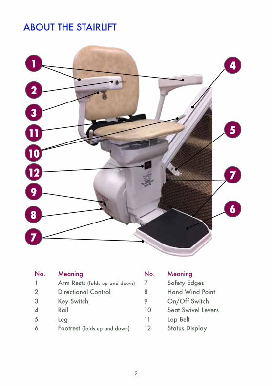
ABOUT THE STAIRLIFT
No. Meaning1 Arm Rests (folds up and down)
2 Directional Control3 Key Switch4 Rail5 Leg6 Footrest (folds up and down)
No. Meaning7 Safety Edges8 Hand Wind Point9 On/Off Switch10 Seat Swivel Levers11 Lap Belt12 Status Display
12
11
10
9
8
7
7
1
2
3
4
5
6
3
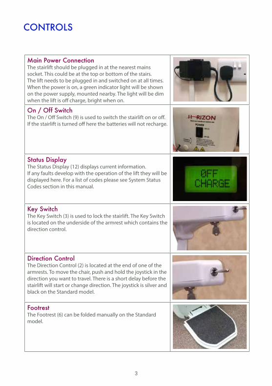
CONTROLS
Main Power ConnectionThe stairlift should be plugged in at the nearest mains socket. This could be at the top or bottom of the stairs. The lift needs to be plugged in and switched on at all times. When the power is on, a green indicator light will be shown on the power supply, mounted nearby. The light will be dim when the lift is off charge, bright when on.
On / Off SwitchThe On / Off Switch (9) is used to switch the stairlift on or off. If the stairlift is turned off here the batteries will not recharge.
Status DisplayThe Status Display (12) displays current information. If any faults develop with the operation of the lift they will be displayed here. For a list of codes please see System Status Codes section in this manual.
Key SwitchThe Key Switch (3) is used to lock the stairlift. The Key Switch is located on the underside of the armrest which contains the direction control.
Direction ControlThe Direction Control (2) is located at the end of one of the armrests. To move the chair, push and hold the joystick in the direction you want to travel. There is a short delay before the stairlift will start or change direction. The joystick is silver and black on the Standard model.
FootrestThe Footrest (6) can be folded manually on the Standard model.

4
SWIVEL SEAT
Swivel SeatFor safety, the seat is locked into one of two positions. In the normal travel position, the seat will be locked into position with your back parallel to the rail. This is so you do not catch your feet on the steps during travel. The lift will not travel unless the seat is locked into this position.
To swivel the seat, push down on one of the Seat Swivel Levers (10), and swivel towards the landing until the seat comes to a stop then release the lever to lock the seat in place. Make sure the seat is locked before you try to sit down or get up from it.
To return the seat to the normal travel position, push down on one of the Seat Swivel Levers (10) and swivel away from the landing until the seat comes to a stop then release the lever to lock the seat in place. The seat only swivels at the top of the stairs. If you try to swivel the seat whilst the lift is moving, the chair will stop.
Safety EdgesThe footrest and the motor unit are fitted with Safety Edges (7). These are pressure pads which will stop the lift if they come into contact with any obstructions. If the lift stops because it has encountered an obstruction, a fault code will be displayed on the diagnostic display. Wait two or three seconds, then reverse away from the obstruction.
Lap BeltThe Lap Belt (11) holds you safely on the seat as you climb or descend the stairs. The Standard model clips together in the center. Push the 2 plastic clips together to release. The lap belt must be used every time the stairlift is used. Do not undo the lap belt until the chair reaches the end of the track.
Seat Swivel Lever
5
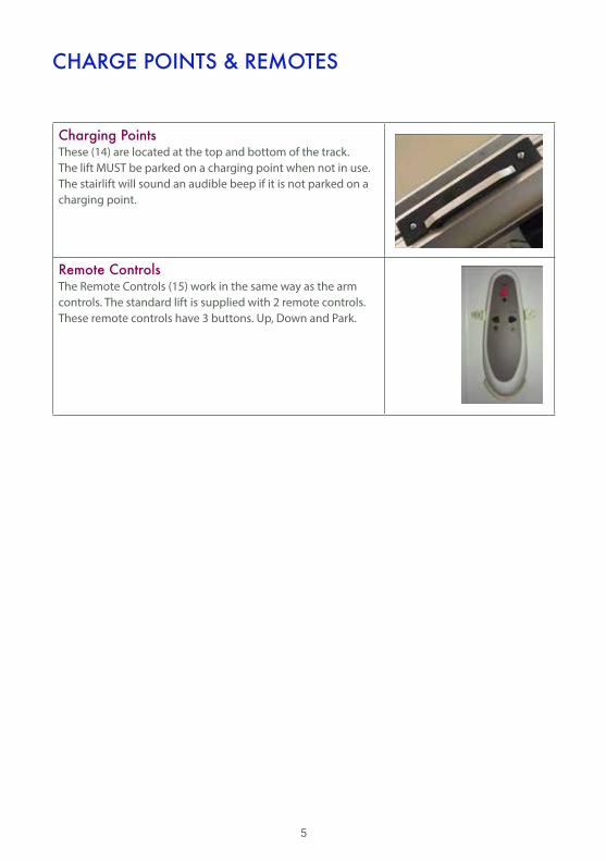
CHARGE POINTS & REMOTES
Charging PointsThese (14) are located at the top and bottom of the track. The lift MUST be parked on a charging point when not in use. The stairlift will sound an audible beep if it is not parked on a charging point.
Remote ControlsThe Remote Controls (15) work in the same way as the arm controls. The standard lift is supplied with 2 remote controls. These remote controls have 3 buttons. Up, Down and Park.

6
TYPICAL PACKAGE LIST
A typical installation will use the following supplied parts:
RAIL LEGS
END CAPS
END PLATE
CHARGING SPLITTER
CHARGING POINT
CABLE GLAND
REMOTE CONTROLHOLSTER HARDWARE END PLATE SCREWS
LEG SCREWSGEAR RACK BOLTS (EXTRA)
MANUAL WINDING TOOL
REMOTE CONTROLS, HOLSTERS & BATTERIES
GEAR LUBRICANT
TOP JOINTING PLATE BOTTOM JOINTING PLATE
7
• 5 x Rail clamps
• 5 x Legs
• 5 x Leg mounts
• 10 x M10 x 16 hex bolts
• 10 x M10 washers
• 10 x M8 x 20 Hex bolts
• 10 x M8 Plain nuts
• 20 x 6.3 x 38 Wood screws
• 1 x Assembled Top Jointing Plate
• 1 x Assembled Bottom Jointing Plate
• 2 x M6 x 10 Countersunk Hex screws
• 8 x M8 x 16 Button Head Hex screws
• 2 x Extrusion end plates
• 2 x Charge Points & insulators
• 4 x Charge Point captive nuts
• 4 x M4 x 10 Countersunk Hex screws
• 2 x Remote controls, holsters & batteries
• 1 x Mains – 27v Transformer & bracket
• 8 x Phillips wood screws
• 8 x Red wall plugs
• 2 x 12v 8.5aH Batteries
• 5m x Blue and Brown 2 core cable
• 2 x M5 x 12 Hex button head rack mounting bolts
• 2 x 2.25m Rails
• 1 x Horizon carriage
• 1 x Seat and Chassis Leg.
• Silicone or PTFE Lubricant for the racking
• 1 x Manual winding handle (to be left with the user)
• 1 x User Guide (to be left with the user)
• 1 x Installation Manual
8
INSTALLATION EQUIPMENT
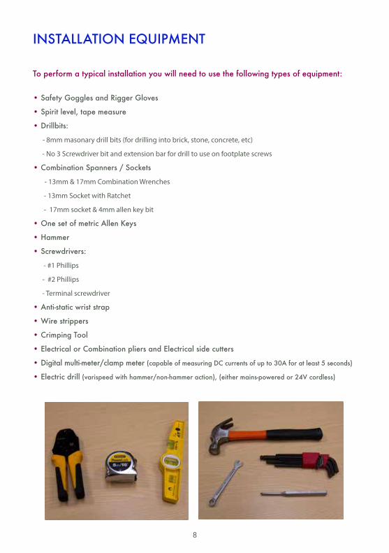
• Safety Goggles and Rigger Gloves
• Spirit level, tape measure
• Drillbits:
- 8mm masonary drill bits (for drilling into brick, stone, concrete, etc)
- No 3 Screwdriver bit and extension bar for drill to use on footplate screws
• Combination Spanners / Sockets
- 13mm & 17mm Combination Wrenches
- 13mm Socket with Ratchet
- 17mm socket & 4mm allen key bit
• One set of metric Allen Keys
• Hammer
• Screwdrivers:
- #1 Phillips
- #2 Phillips
- Terminal screwdriver
• Anti-static wrist strap
• Wire strippers
• Crimping Tool
• Electrical or Combination pliers and Electrical side cutters
• Digital multi-meter/clamp meter (capable of measuring DC currents of up to 30A for at least 5 seconds)
• Electric drill (varispeed with hammer/non-hammer action), (either mains-powered or 24V cordless)
To perform a typical installation you will need to use the following types of equipment:
9
HEALTH & SAFETY GUIDANCE
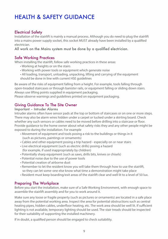
Electrical SafetyInstallation of the stairlift is mainly a manual process. Although you do need to plug the stairlift into a mains power supply socket, this socket MUST already have been installed by a qualified electrician.All work on the Mains system must be done by a qualified electrician.
Safe Working PracticesWhen installing the stairlift, follow safe working practices in these areas: • Working at heights or on the stairs • Working with power tools or equipment which generate noise • All loading, transport, unloading, unpacking, lifting and carrying of the equipment should be done in line with current HSE guidelines
Be aware of the risks of equipment falling from a height. For example, tools falling through open-treaded staircases or through banister rails, or equipment falling or sliding down stairs.Always use lifting points supplied in equipment packaging.Please observe warnings and guidelines printed on equipment packaging.
Giving Guidance To The Site OwnerImportant – Intruder AlarmsIntruder alarms often have sensor pads at the top or bottom of staircases or on one or more steps. There may also be alarm wires hidden under a carpet or tucked under a skirting board. Check whether any such sensors or cables need to be moved before drilling into a staircase or floor.Provide guidance to the home owner about what safety risks they and any other people might be exposed to during the installation. For example • Movement of equipment and tools posing a risk to the buildings or things in it (such as pictures, paintings or ornaments) • Cables and other equipment posing a trip hazard - especially on or near stairs • Live electrical equipment (such as electric drills) posing a hazard (for example, if used inappropriately by children) • Potentially sharp equipment (such as saws, drills bits, knives or chisels) • Potential noise due to the use of power tools • Potential creation of airborne dust • Remember to let the resident know you will take them through how to use the stairlift, so they can let some-one else know what time a demonstration might take place • Resident must keep boarding/exit areas of the stairlift clear and well lit to a level of 50 lux.
Preparing The WorkplaceBefore you start the installation, make sure of a Safe Working Environment, with enough space to assemble the stairlift assembly and for you to work around it.
Make sure any loose or fragile property (such as pictures or ornaments) are located in a safe place away from the potential working area. Inspect the area for potential obstructions such as central heating pipes, hidden cables, underfloor heating, etc. The work area should be well lit. If sufficient lighting is not available, temporary lighting should be used. The stair treads should be inspected for their suitability of supporting the installed machinery.
If in doubt, a qualified person should be engaged to check suitability.

10
INSTALLING THE STAIRLIFT
The stairlift must be fitted so that it does not prevent doors to and in the building from opening and closing.
Laying Out The ComponentsEach stairlift consists of 3 boxes, the Drive Unit, the Chair and the Chassis Leg. The Chassis leg box also contains the parts kit.

11
ASSEMBLING THE RAIL
RAIL PARTS
TOP JOINTING PLATE
BOTTOM JOINTING PLATE TOP VIEW BOTTOM JOINTING PLATE SIDE VIEW
x x
TOP RAIL SECTION
BOTTOM RAIL SECTIONCHARGING POINT CHARGING CABLE
TOP OF RAIL
BOTTOM OF RAIL
UPPER ENDLOWER END
12
TOP JOINTING PLATE
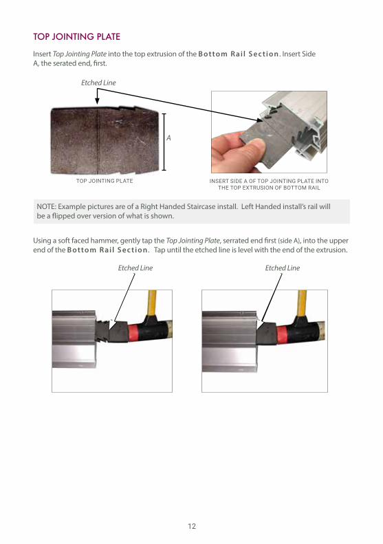
Insert Top Jointing Plate into the top extrusion of the B ottom R ai l S ec t ion . Insert Side A, the serated end, first.
Using a soft faced hammer, gently tap the Top Jointing Plate, serrated end first (side A), into the upper end of the B ottom R ai l S ec t ion . Tap until the etched line is level with the end of the extrusion.
TOP JOINTING PLATE INSERT SIDE A OF TOP JOINTING PLATE INTO THE TOP EXTRUSION OF BOTTOM RAIL
A
Etched Line
Etched Line Etched Line
NOTE: Example pictures are of a Right Handed Staircase install. Left Handed install’s rail willbe a flipped over version of what is shown.
13
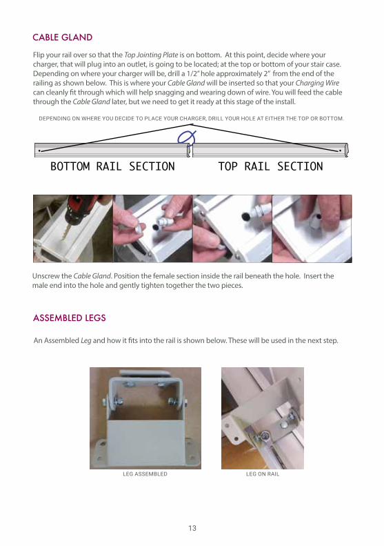
An Assembled Leg and how it fits into the rail is shown below. These will be used in the next step.
ASSEMBLED LEGS
LEG ASSEMBLED LEG ON RAIL
CABLE GLAND
Flip your rail over so that the Top Jointing Plate is on bottom. At this point, decide where your charger, that will plug into an outlet, is going to be located; at the top or bottom of your stair case. Depending on where your charger will be, drill a 1/2” hole approximately 2” from the end of the railing as shown below. This is where your Cable Gland will be inserted so that your Charging Wire can cleanly fit through which will help snagging and wearing down of wire. You will feed the cable through the Cable Gland later, but we need to get it ready at this stage of the install.
Unscrew the Cable Gland. Position the female section inside the rail beneath the hole. Insert the male end into the hole and gently tighten together the two pieces.
BOTTOM RAIL SECTION TOP RAIL SECTION
DEPENDING ON WHERE YOU DECIDE TO PLACE YOUR CHARGER, DRILL YOUR HOLE AT EITHER THE TOP OR BOTTOM.
14
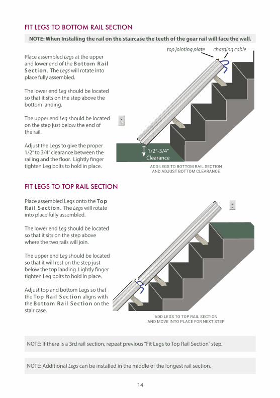
Place assembled Legs at the upper and lower end of the B ottom R ai l S ec t ion . The Legs will rotate into place fully assembled.
The lower end Leg should be located so that it sits on the step above the bottom landing.
The upper end Leg should be located on the step just below the end of the rail.
Adjust the Legs to give the proper 1/2” to 3/4” clearance between the railing and the floor. Lightly finger tighten Leg bolts to hold in place.
Place assembled Legs onto the Top R ai l S ec t ion . The Legs will rotate into place fully assembled.
The lower end Leg should be located so that it sits on the step above where the two rails will join.
The upper end Leg should be located so that it will rest on the step just below the top landing. Lightly finger tighten Leg bolts to hold in place.
Adjust top and bottom Legs so that the Top R ai l S ec t ion aligns with the B ottom R ai l S ec t ion on the stair case.
NOTE: When Installing the rail on the staircase the teeth of the gear rail will face the wall.
NOTE: If there is a 3rd rail section, repeat previous “Fit Legs to Top Rail Section” step.
NOTE: Additional Legs can be installed in the middle of the longest rail section.
FIT LEGS TO BOTTOM RAIL SECTION
FIT LEGS TO TOP RAIL SECTION
1/2”-3/4”Clearance
ADD LEGS TO BOTTOM RAIL SECTION AND ADJUST BOTTOM CLEARANCE
ADD LEGS TO TOP RAIL SECTION AND MOVE INTO PLACE FOR NEXT STEP
top jointing plate charging cable
15
TOP JOINTING PLATE
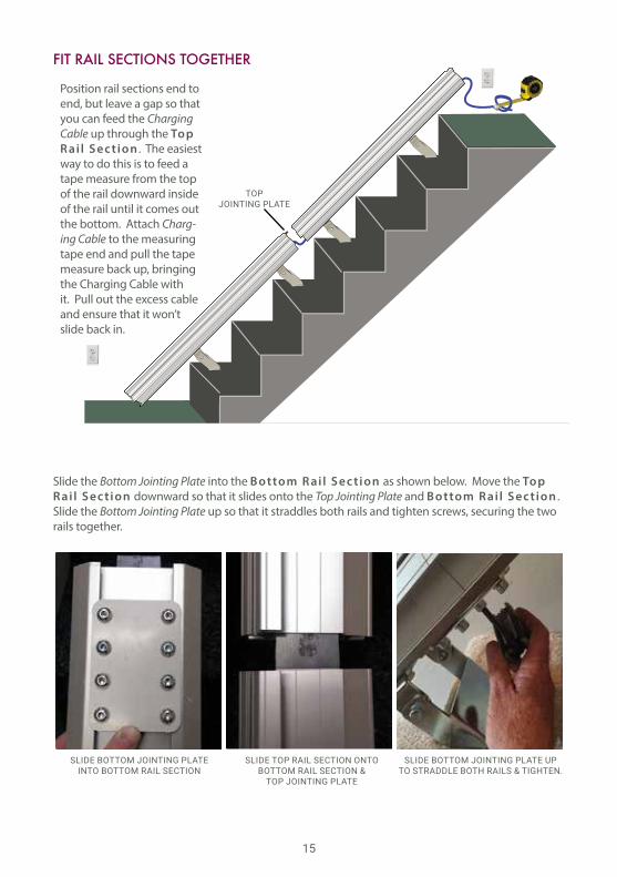
Position rail sections end to end, but leave a gap so that you can feed the Charging Cable up through the Top R ai l S ec t ion . The easiest way to do this is to feed a tape measure from the top of the rail downward inside of the rail until it comes out the bottom. Attach Charg-ing Cable to the measuring tape end and pull the tape measure back up, bringing the Charging Cable with it. Pull out the excess cable and ensure that it won’t slide back in.
FIT RAIL SECTIONS TOGETHER
SLIDE BOTTOM JOINTING PLATE INTO BOTTOM RAIL SECTION
SLIDE TOP RAIL SECTION ONTO BOTTOM RAIL SECTION &
TOP JOINTING PLATE
SLIDE BOTTOM JOINTING PLATE UP TO STRADDLE BOTH RAILS & TIGHTEN.
Slide the Bottom Jointing Plate into the B ottom R ai l S ec t ion as shown below. Move the Top R ai l S ec t ion downward so that it slides onto the Top Jointing Plate and B ottom R ai l S ec t ion . Slide the Bottom Jointing Plate up so that it straddles both rails and tighten screws, securing the two rails together.
16
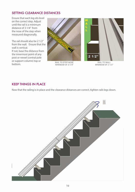
Ensure that each leg sits level on the correct step. Adjust until the rail is a minimum distance of 3 1/4” from the nose of the step when measured diagnonally.
The rail should also be 2 1/2” from the wall. Ensure that the wall is vertical. If not, base the distance from the innermost point of any post or newel (central pole or support column) top or bottom.
SETTING CLEARANCE DISTANCES
KEEP THINGS IN PLACE
WALL
2 1/2”RAIL TO STEP NOSEMINIMUM OF 3 1/4”
RAIL TO WALLMINIMUM OF 2 1/2”
NEW PICTURE
Now that the railing is in place and the clearance distances are correct, tighten rails legs down.

17
NEW PICTURE
Unpack Drive Unit and inspect the bottom of the Drive Unit to be sure limit switch buttons and springs are in place.
Load the Drive Unit at the top of the track carefully. When loading the Drive Unit, please be aware that it must be supported so that switches DO NOT contact the rail.
Ensure that the lower carriage rollers are located into rail extrusion channels correctly and that the drive and OSG (Over Speed Governor) pinions do not catch. Lower the Drive Unit slowly down the rail until the drive pinion rests against the lower gear rack section.
Do not allow Drive Unit to free roll down the rail. Manually lower until it rests against the gear rack.
UNPACK DRIVE UNIT
LOAD DRIVE UNIT
DRIVE UNIT
NOTE: Your stair lift should come with a Gear Rack pre-installed in the B ottom R ai l S ec t ion . If by some chance there isn’t one pre-installed, install only 1 Gear Rack by sliding it all the way down the rail, gear teeth facing outwards.
DRIVE UNITLIMIT SWITCH BUTTONS & SPRINGS
18
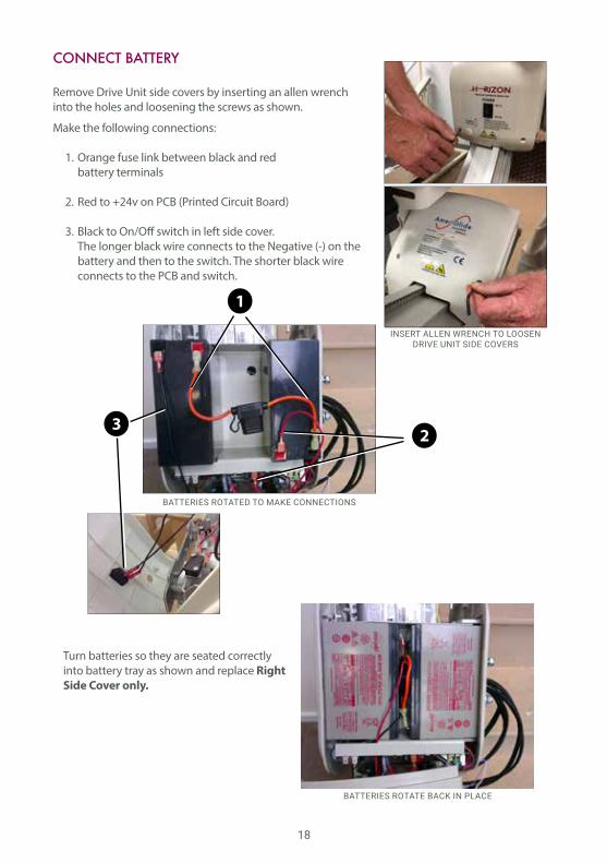
Make the following connections:
1. Orange fuse link between black and red battery terminals
2. Red to +24v on PCB (Printed Circuit Board)
3. Black to On/Off switch in left side cover. The longer black wire connects to the Negative (-) on the battery and then to the switch. The shorter black wire connects to the PCB and switch.
Remove Drive Unit side covers by inserting an allen wrench into the holes and loosening the screws as shown.
Turn batteries so they are seated correctly into battery tray as shown and replace Right Side Cover only.
INSERT ALLEN WRENCH TO LOOSEN DRIVE UNIT SIDE COVERS
CONNECT BATTERY
BATTERIES ROTATE BACK IN PLACE
BATTERIES ROTATED TO MAKE CONNECTIONS
2
1
3
19
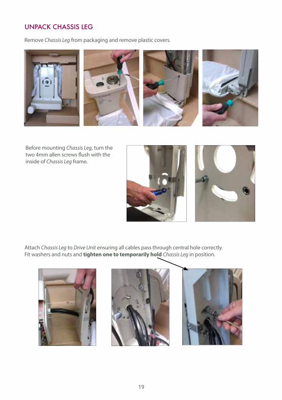
Remove Chassis Leg from packaging and remove plastic covers.
Attach Chassis Leg to Drive Unit ensuring all cables pass through central hole correctly. Fit washers and nuts and tighten one to temporarily hold Chassis Leg in position.
Before mounting Chassis Leg, turn the two 4mm allen screws flush with the inside of Chassis Leg frame.
UNPACK CHASSIS LEG
20
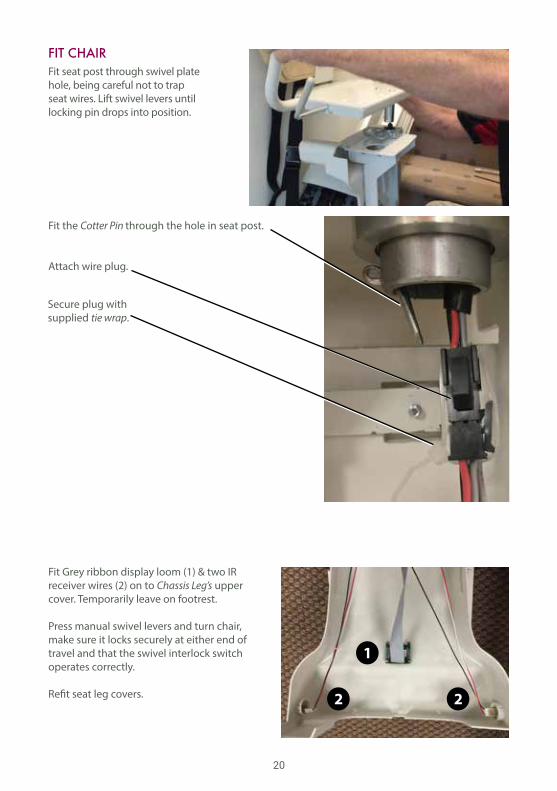
Fit seat post through swivel plate hole, being careful not to trap seat wires. Lift swivel levers until locking pin drops into position.
Fit the Cotter Pin through the hole in seat post.
Attach wire plug.
Fit Grey ribbon display loom (1) & two IR receiver wires (2) on to Chassis Leg’s upper cover. Temporarily leave on footrest.
Press manual swivel levers and turn chair, make sure it locks securely at either end of travel and that the swivel interlock switch operates correctly.
Refit seat leg covers.
FIT CHAIR
2 2
1
Secure plug withsupplied tie wrap.
21
The Key is attached to the arm with a tie wrap. Detach it, insert into keyswitch under the armrest and turn clockwise.
NOTE: The key must be installed and turned on for the lift to function.
NOTE: There will be a 3-5 second delay before the lift will move when the arm switch is activated.
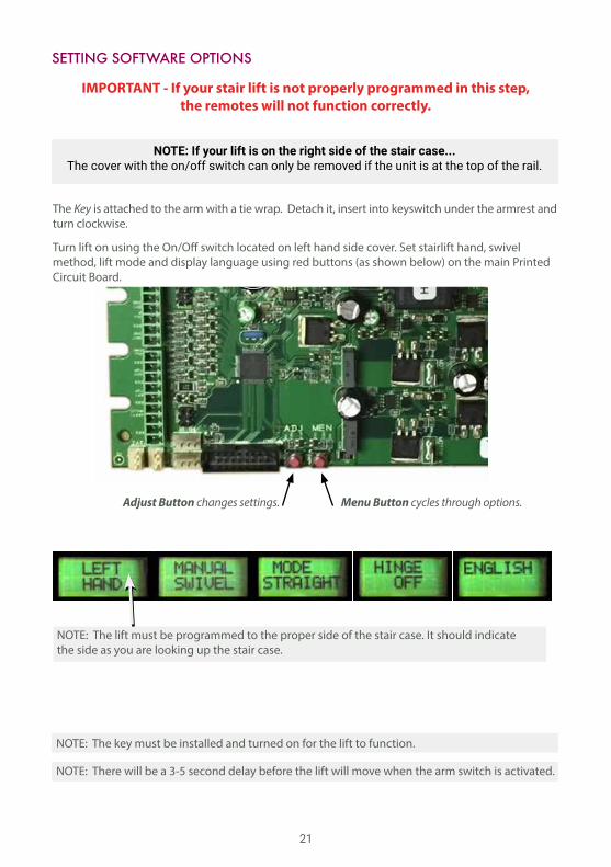
SETTING SOFTWARE OPTIONS
Turn lift on using the On/Off switch located on left hand side cover. Set stairlift hand, swivel method, lift mode and display language using red buttons (as shown below) on the main Printed Circuit Board.
NOTE: The lift must be programmed to the proper side of the stair case. It should indicate the side as you are looking up the stair case.
IMPORTANT - If your stair lift is not properly programmed in this step, the remotes will not function correctly.
Menu Button cycles through options.Adjust Button changes settings.
NOTE: If your lift is on the right side of the stair case...The cover with the on/off switch can only be removed if the unit is at the top of the rail.
22
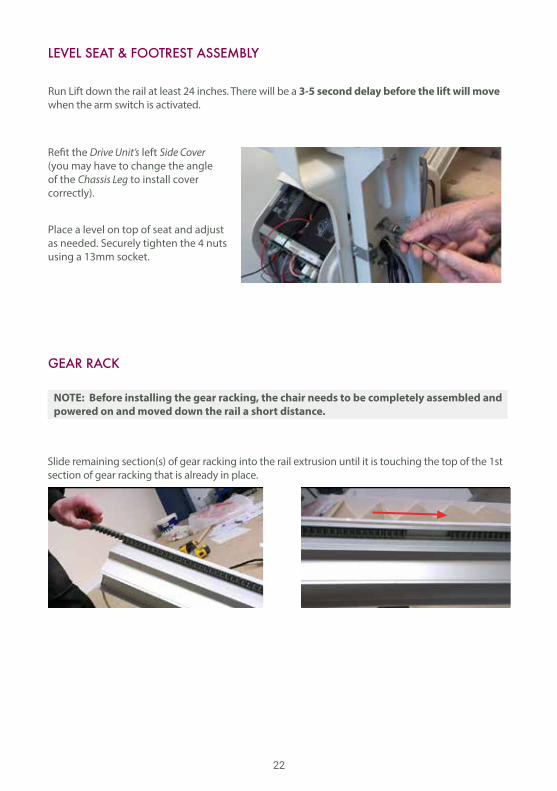
Place a level on top of seat and adjust as needed. Securely tighten the 4 nuts using a 13mm socket.
Refit the Drive Unit’s left Side Cover (you may have to change the angle of the Chassis Leg to install cover correctly).
LEVEL SEAT & FOOTREST ASSEMBLY
Run Lift down the rail at least 24 inches. There will be a 3-5 second delay before the lift will move when the arm switch is activated.
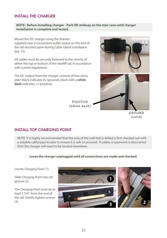
GEAR RACK
Slide remaining section(s) of gear racking into the rail extrusion until it is touching the top of the 1st section of gear racking that is already in place.
NOTE: Before installing the gear racking, the chair needs to be completely assembled and powered on and moved down the rail a short distance.
23
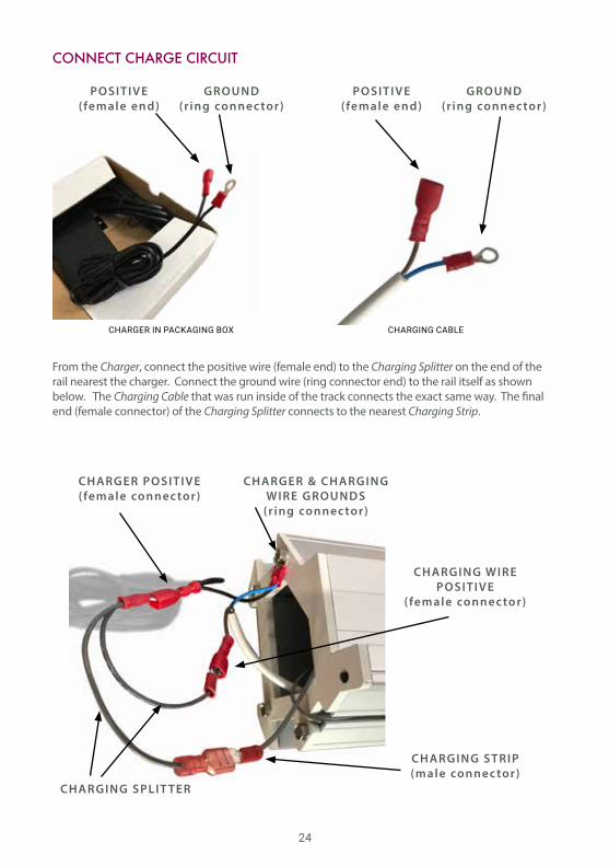
Mount the DC charger using the bracket supplied near a convenient outlet socket on the end of the rail decided upon during Cable Gland installation (pg. 13).
All cables must be securely fastened to the vicinity of either the top or bottom of the stairlift rail, in accordance with current regulations.
The DC output from the charger consists of two wires, plain black indicates 0v (ground), black with a white dash indicates +v (positive).
INSTALL THE CHARGER
NOTE: Before installing charger - Park lift midway on the stair case until charger installation is complete and tested.
POSITIVE(white dash)
GROUND(sol id)
INSTALL TOP CHARGING POINT
Locate Charging Point (1).
Slide Charging Point into rail groove (2).
The Charging Point must be at least 2 3/4” from the end of the rail. Gently tighten screws (3). 2
1
3
NOTE: It is highly recommended that the area of the wall that is drilled is first checked out with a suitable cable/pipe locator to ensure it is safe to proceed. If cables or pipework is discovered then the charger will need to be located elsewhere.
Leave the charger unplugged until all connections are made and checked.
24
From the Charger, connect the positive wire (female end) to the Charging Splitter on the end of the rail nearest the charger. Connect the ground wire (ring connector end) to the rail itself as shown below. The Charging Cable that was run inside of the track connects the exact same way. The final end (female connector) of the Charging Splitter connects to the nearest Charging Strip.
CONNECT CHARGE CIRCUIT
CHARGER IN PACKAGING BOX CHARGING CABLE
POSITIVE(female end)
POSITIVE(female end)
CHARGER POSITIVE(female connec tor)
GROUND(ring connec tor)
GROUND(ring connec tor)
CHARGER & CHARGING WIRE GROUNDS
(r ing connec tor)
CHARGING WIRE POSITIVE
(female connec tor)
CHARGING STRIP(male connec tor)
CHARGING SPLIT TER
25
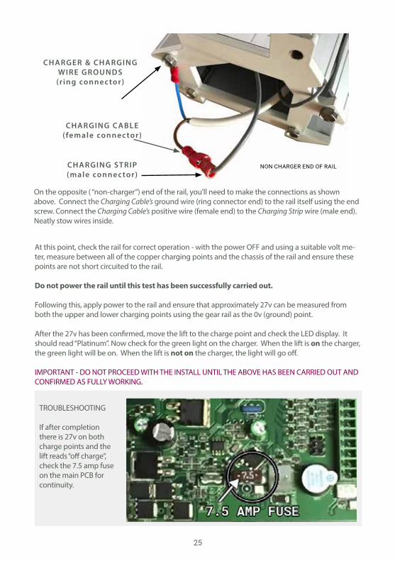
At this point, check the rail for correct operation - with the power OFF and using a suitable volt me-ter, measure between all of the copper charging points and the chassis of the rail and ensure these points are not short circuited to the rail.
Do not power the rail until this test has been successfully carried out.
Following this, apply power to the rail and ensure that approximately 27v can be measured from both the upper and lower charging points using the gear rail as the 0v (ground) point.
After the 27v has been confirmed, move the lift to the charge point and check the LED display. It should read “Platinum”. Now check for the green light on the charger. When the lift is on the charger, the green light will be on. When the lift is not on the charger, the light will go off.
IMPORTANT - DO NOT PROCEED WITH THE INSTALL UNTIL THE ABOVE HAS BEEN CARRIED OUT AND CONFIRMED AS FULLY WORKING.
NON CHARGER END OF RAIL
TROUBLESHOOTING
If after completion there is 27v on both charge points and the lift reads “off charge”, check the 7.5 amp fuse on the main PCB for continuity.
CHARGER & CHARGING WIRE GROUNDS
(r ing connec tor)
CHARGING STRIP(male connec tor)
CHARGING C ABLE(female connec tor)
On the opposite ( “non-charger”) end of the rail, you’ll need to make the connections as shown above. Connect the Charging Cable’s ground wire (ring connector end) to the rail itself using the end screw. Connect the Charging Cable’s positive wire (female end) to the Charging Strip wire (male end). Neatly stow wires inside.
26
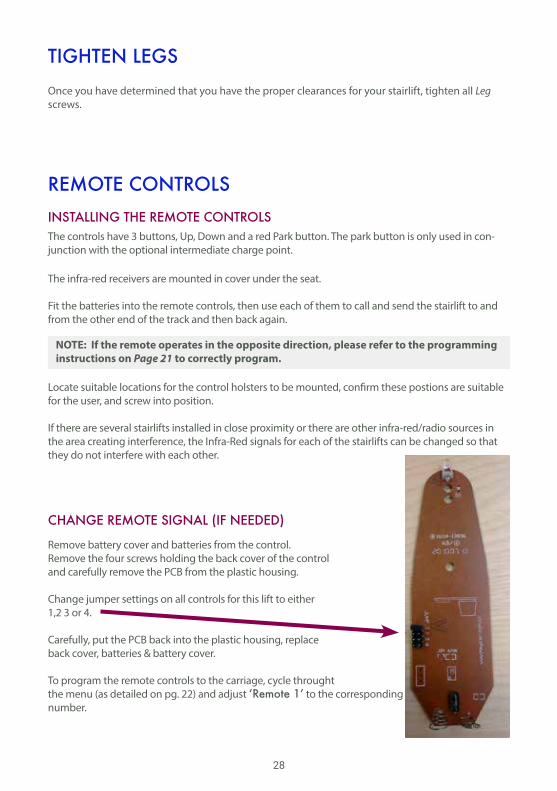
FIT ON END CAP
Fit End Caps onto the ends of the rails.
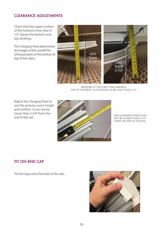
CLEARANCE ADJUSTMENTS
Check that the upper surface of the footrest is less than 6 1/2” above the bottom and top landings.
The Charging Point determines the height of the stairlift fin-ishing postion at the bottom & top of the stairs.
Adjust the Charging Point to suit the primary user’s height and comfort. It can not be closer than 2 3/4” from the end of the rail.
MEASURE AT TOP & BOTTOM LANDINGSTOP OF FOOTREST TO FLOOR HAS TO BE LESS THAN 6 1/2”
END CHARGING POINTS CAN NOT BE CLOSER THAN 2 3/4” FROM THE END OF THE RAIL
LESSTHAN6 1/2” LESS
THAN6 1/2”

27
STAIRLIFT TEST RUN PT. 1
Important: If there are any issues with the stairlift, the system may display System Status Codes.Refer to the System Status Codes section for more details of what these codes mean.
To test run the stairlift (unladen): Make sure the area covered by the movement of the stairlift is free of obstructions.
Fold down the footrest and swivel the seat into correct travel position. Leave the armrests in the upright position. Do not allow any weight to rest on the carriage as yet.
Run the unladen stairlift to the very bottom of the track. While the stairlift is travelling check:
1. Footrest, folded down, to riser clearance.
2. Armrest and seat back clearance, especially on staircases with low bulkheads.
3. Seat back clearance to wall or railing posts.
4. Arm rest clearance to wall when swivelled.
At the bottom check that the stairlift is charging correctly and the footrest is at the correct height to allow the user to easily access the stairlift. When the lift is properly charging, the word “Platinum” will be displayed on the LED screen.
Run the stairlift to the top of the track while checking all above points.
At the top check that the stairlift is charging correctly and the footrest is at the correct height to allow the user to easily access the stairlift. Also check the swivel radius to ensure that the downside armrest or seat back does not come into contact with the opposite side of the staircase.
TEST RUNNING STAIRLIFT - EMPTY
I f the footrest contac ts any step r ise. . .Fold arms, seat and footrest into the UP position. Remove foot screws and move entire rail forward by moving the feet positions closer to the nose of the step.
I f the chair contac ts wal l when swiveled. . .Move the entire rail farther away from the wall.
B e careful that the chair doesn’t t ip over whi le mak ing adjustments.
28
TIGHTEN LEGS
The controls have 3 buttons, Up, Down and a red Park button. The park button is only used in con-junction with the optional intermediate charge point.
The infra-red receivers are mounted in cover under the seat.
Fit the batteries into the remote controls, then use each of them to call and send the stairlift to and from the other end of the track and then back again.
Locate suitable locations for the control holsters to be mounted, confirm these postions are suitable for the user, and screw into position.
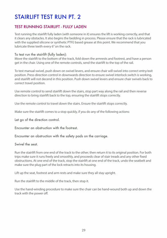
If there are several stairlifts installed in close proximity or there are other infra-red/radio sources in the area creating interference, the Infra-Red signals for each of the stairlifts can be changed so that they do not interfere with each other.
Remove battery cover and batteries from the control. Remove the four screws holding the back cover of the control and carefully remove the PCB from the plastic housing.
Change jumper settings on all controls for this lift to either 1,2 3 or 4.
Carefully, put the PCB back into the plastic housing, replace back cover, batteries & battery cover.
To program the remote controls to the carriage, cycle throught the menu (as detailed on pg. 22) and adjust ‘Remote 1’ to the corresponding jumper number.
REMOTE CONTROLSINSTALLING THE REMOTE CONTROLS
CHANGE REMOTE SIGNAL (IF NEEDED)
NOTE: If the remote operates in the opposite direction, please refer to the programming instructions on Page 21 to correctly program.
Once you have determined that you have the proper clearances for your stairlift, tighten all Leg screws.
29
Test running the stairlift fully laden (with someone in it) ensures the lift is working correctly, and that it clears any obstacles. It also begins the bedding in process. Please ensure that the rack is lubricated with the supplied silicone or synthetic PTFE based grease at this point. We recommend that you lubricate three teeth every 6” on the rack.
To test run the stairlift (fully laden): Move the stairlift to the bottom of the track, fold down the armrests and footrest, and have a person get in the chair. Using one of the remote controls, send the stairlift to the top of the rail.
To test manual swivel, push down on swivel levers, and ensure chair will swivel into correct entry/exit position. Press direction control in downwards direction to ensure swivel interlock switch is working, and stairlift will not decend in this position. Push down swivel levers and ensure chair swivels back to correct travel position.
Use remote control to send stairlift down the stairs, stop part way along the rail and then reverse direction to bring stairlift back to the top, ensuring the stairlift stops correctly.
Use the remote control to travel down the stairs. Ensure the stairlift stops correctly.
Make sure the stairlift comes to a stop quickly, if you do any of the following actions:
Let go of the direction control.
Encounter an obstruction with the footrest.
Encounter an obstruction with the safety pads on the carriage.
Swivel the seat.
Run the stairlift from one end of the track to the other; then return it to its original position. For both trips make sure it runs freely and smoothly, and proceeds clear of stair treads and any other fixed obstructions. At one end of the track, stop the stairlift at one end of the track, undo the seatbelt and make sure the plug part of the lock retracts into its housing. Lift up the seat, footrest and arm rests and make sure they all stay upright. Run the stairlift to the middle of the track, then stop it. Use the hand-winding procedure to make sure the chair can be hand-wound both up and down the track with the power off.
STAIRLIFT TEST RUN PT. 2TEST RUNNING STAIRLIFT - FULLY LADEN
30
Blac
k 0V
DC
Blue
0V
DC
Brow
n 24
-27v
DC
to
Opp
osite
end
Cha
rge
Strip
Grey
24-
27v
DC
to C
harg
e St
rip
Char
ger
Blac
k/W
hite
27
.6V
DC
Blac
k 0V
DC
OV/
Grou
nd to
Rai
l
Rail
Extr
usio
n
Wiri
ng D
iagr
am
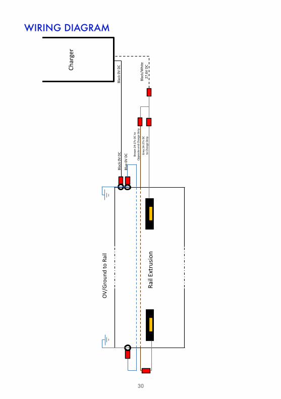
WIRING DIAGRAM
31
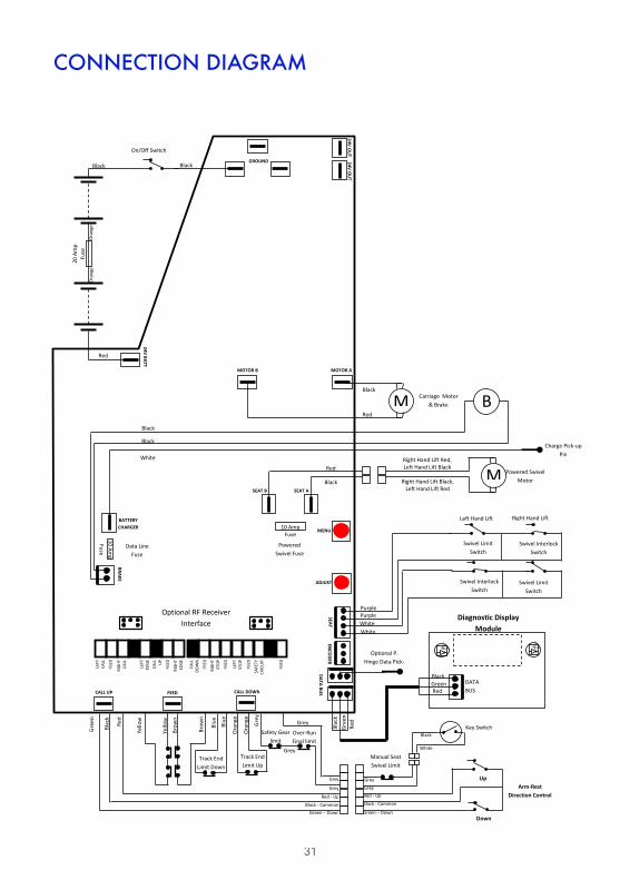
Connection Diagram
LEFT
CA
LL
FEED
RIGH
T CA
LL
LEFT
ED
GE
CALL
UP
FEED
RIGH
T ED
GE
CALL
DO
WN
FEED
RIGH
T ST
OP
FEED
LEFT
ST
OP
FEED
SAFE
TY
CIRC
UIT
FEED
10 Amp Fuse
GROUND
MOTOR B MOTOR A
SEAT B SEAT A
MENU
ADJUST
24V BATT
BATTERY CHARGER
BRAKE
DATA BUS
SEAT EN
CODER
CALL UP FEED CALL DOWN
24V OU
T 24V O
UT
Diagnostic Display Module
DATA BUS
Manual Seat Swivel Limit
Arm-Rest Direction Control
Grey
Grey
Red - Up
Black - Common
Green – Down
Black
White
Up
Down
Brow
n
Gre
en
Blac
k
Red
Blue
Yello
w
Yello
w
Brow
n
Key Switch
Track End Limit Down
Ora
nge
Track End Limit Up
Gre
y
Grey
Safety Gear limit
Over-Run Final limit
Grey
Green – Down Black - Common
Red - Up
Grey
Grey
Blue
Ora
nge
20 A
mp
Fuse
O
rang
e
On/Off Switch
M
Charge Pick-up Pin
Powered Swivel Motor
Carriage Motor & Brake B
M
Swivel Interlock Switch
Swivel Limit Switch
Black Black
Red
Red
Black
Red
Black
Black
Black
White
White White
Purple Purple
Black
Red Green
Blac
k
Red
Gre
en
Ora
nge
Swivel Interlock Switch
Swivel Limit Switch
Left Hand Lift Right Hand Lift
Optional RF Receiver Interface
Optional P. Hinge Data Pick-
up Pin
10 Amp
Fuse
Data Line Fuse
Powered Swivel Fuse
Fuse
Right Hand Lift Red, Left Hand Lift Black
Right Hand Lift Black, Left Hand Lift Red
CONNECTION DIAGRAM

32
TECHNICAL INFORMATION
Weight LimitsThe stairlift has been designed to carry one person only, in a seated position. The stairlift has a maximum weight limit of 300 lbs.
Operating Periods/Excessive UseThe stairlift has been designed to run for four minutes with a break of at least six minutes afterwards. If you use the stairlift too often without taking a break, the motor will not cool down between journeys and may become damaged.
Replacement BatteriesWe recommend that the batteries in each remote control are renewed at least every eighteen (18) months. This is the responsibilty of the customer.
MaintenanceTo maintain safe and reliable operation, the standard stairlift needs a annual safety inspection and service.
UpholsteryCarelessness with matches, cigarettes and so on can cause a fire. The upholstery material used on your stairlift has been tested for compliance with BS5852.
Hand Winding the StairliftIf necessary, for example to release the safety gear after the OSG has activated or to return the carriage from an over-run position, the stairlift can be manually hand-wound using the supplied winding handle. If the OSG has been activated, the carriage should only be hand-wound in the upwards direction. Hand winding should only be attempted by, or under the supervision of a competent stairlift engineer.
To hand-wind the stairlift:
•Turn power off.
•Fully insert the winding handle into the Emergency Hand Wind Mechanism Socket (8)
•Keeping the handle fully inserted, carefully rotate it as needed
•If you rotate the handle clockwise, this will move the chair to the right
•If you rotate the handle anti-clockwise, this will move the chair to the left
•Never use the stairlift when the winding handle is in the socket
•Never hand-wind the lift with a power drill
Important: Modifications which have not been expressly approved by the manufacturer may void the warranty and may cause damage. Your stairlift should be inspected and maintained by a Platinum approved service engineer.
33
Never exit seat without first turning towards staircase and ensuring that it locks into position.
Always exit upwards.
TECHNICAL INFORMATION
Outdoor LiftsThe supplied cover must be used when the stairlift is not in use.
Releasing a Trapped UserIf a user becomes trapped on the stairlift due to a fault, they should be assisted from the chair in the following way:
•Lift one of the manual swivel levers and rotate the carriage towards the staircase until seat locks into swivelled position.
•Release users seatbelt
•Lift manual swivel levers and return seat to original position.
34
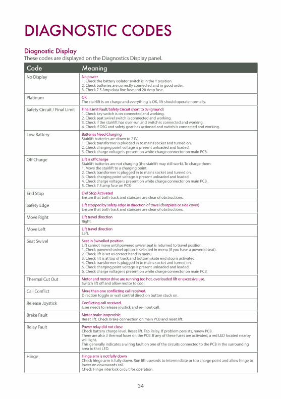
DIAGNOSTIC CODESDiagnostic DisplayThese codes are displayed on the Diagnostics Display panel.
Code MeaningNo Display No power
1. Check the battery isolator switch is in the ‘I’ position.2. Check batteries are correctly connected and in good order.3. Check 7.5 Amp data line fuse and 20 Amp fuse.
Platinum OKThe stairlift is on charge and everything is OK, lift should operate normally.
Safety Circuit / Final Limit Final Limit Fault/Safety Circuit short to 0v (ground)1. Check key switch is on connected and working.2. Check seat swivel switch is connected and working.3. Check if the stairlift has over-run and switch is connected and working.4. Check if OSG and safety gear has actioned and switch is connected and working.
Low Battery Batteries Need ChargingStairlift batteries are down to 21V.1. Check transformer is plugged in to mains socket and turned on.2. Check charging point voltage is present unloaded and loaded.3. Check charge voltage is present on white charge connector on main PCB.
Off Charge Lift is off ChargeStairlift batteries are not charging (the stairlift may still work). To charge them:1. Move the stairlift to a charging point.2. Check transformer is plugged in to mains socket and turned on.3. Check charging point voltage is present unloaded and loaded.4. Check charge voltage is present on white charge connector on main PCB.5. Check 7.5 amp fuse on PCB
End Stop End Stop ActivatedEnsure that both track and staircase are clear of obstructions.
Safety Edge Lift stopped by safety edge in direction of travel (footplate or side cover)Ensure that both track and staircase are clear of obstructions.
Move Right Lift travel directionRight.
Move Left Lift travel directionLeft.
Seat Swivel Seat in Swivelled positionLift cannot move until powered swivel seat is returned to travel position.1. Check powered swivel option is selected in menu (if you have a powered seat).2. Check lift is set as correct hand in menu.3. Check lift is at top of track and bottom skate end stop is activated. 4. Check transformer is plugged in to mains socket and turned on.5. Check charging point voltage is present unloaded and loaded.6. Check charge voltage is present on white charge connector on main PCB.
Thermal Cut Out Motor and motor drive are running too hot, overloaded lift or excessive use.Switch lift off and allow motor to cool.
Call Conflict More than one conflicting call received.Direction toggle or wall control direction button stuck on.
Release Joystick Conflicting call received.User needs to release joystick and re-input call.
Brake Fault Motor brake inoperable.Reset lift. Check brake connection on main PCB and reset lift.
Relay Fault Power relay did not closeCheck battery charge level. Reset lift. Tap Relay. If problem persists, renew PCB.There are also 3 thermal fuses on the PCB. If any of these fuses are activated, a red LED located nearby will light.This generally indicates a wiring fault on one of the circuits connected to the PCB in the surrounding area to that LED.
Hinge Hinge arm is not fully downCheck hinge arm is fully down. Run lift upwards to intermediate or top charge point and allow hinge to lower on downwards call. Check Hinge interlock circuit for operation.

35
ENGINEER’S MENUEngineer’s Diagnostics and SettingsFurther diagnostics and settings are available by cycling through the menu system.
Code MeaningPosition 12345 Lifts current position on rail. Bottom end stop is 00000. Press and hold menu button to re-program.
Remote 1/2/3/4 Shows current Remote channel selection. Press adjust button to change.
Right / Left Hand Shows current installation hand selected. Press adjust button to change.
Quiet Travel / Travel Alarm Shows current travel alarm selection. Press adjust button to change.
Landing Stop /Pass Shows current landing selection. Press adjust button to change.
Powered / Manual Swivel Shows current swivel selection. Press adjust button to change.
Edge 123 Number of sensitive edge trips since last engineer reset. Press adjust button to reset to 0.
Low Batt 123 Number of low battery events since last engineer reset. Press adjust button to reset to 0.
Trips 12345 Number of trips (up or down) done by control system. Not resettable.
Safety 123 Number of safety circuit trips since last engineer reset. Press adjust button to reset to 0.
Brake 123 Number of brake faults since last engineer reset. Press adjust button to reset to 0.
Relay 123 Number of relay faults since last engineer reset. Press adjust button to reset to 0.
Lost Position 123 Number of times position has been lost since last engineer reset. Press adjust button to reset to 0.
Battery Bar (bar display 1-8)
A bar display of battery voltage. Approx. 21V (all off) to 27V (all on).
Low battery Battery below 21V.
Mains Power, Battery Power and Power CutsThe DC charger supplies power to a set of large internal batteries. These batteries then power the motor which lifts the chair up and down the stairs. If the mains power fails, you can continue to use the stairlift for a short while as the batteries store enough power to allow you up and down the stairs a few times.
36
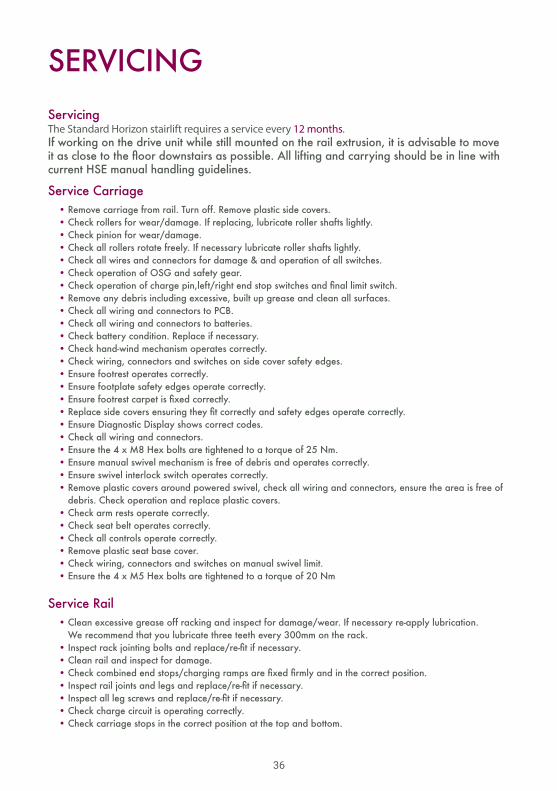
SERVICINGServicingThe Standard Horizon stairlift requires a service every 12 months. If working on the drive unit while still mounted on the rail extrusion, it is advisable to move it as close to the floor downstairs as possible. All lifting and carrying should be in line with current HSE manual handling guidelines.
Service Carriage • Remove carriage from rail. Turn off. Remove plastic side covers. • Check rollers for wear/damage. If replacing, lubricate roller shafts lightly. • Check pinion for wear/damage. • Check all rollers rotate freely. If necessary lubricate roller shafts lightly. • Check all wires and connectors for damage & and operation of all switches. • Check operation of OSG and safety gear. • Check operation of charge pin,left/right end stop switches and final limit switch. • Remove any debris including excessive, built up grease and clean all surfaces. • Check all wiring and connectors to PCB. • Check all wiring and connectors to batteries. • Check battery condition. Replace if necessary. • Check hand-wind mechanism operates correctly. • Check wiring, connectors and switches on side cover safety edges. • Ensure footrest operates correctly. • Ensure footplate safety edges operate correctly. • Ensure footrest carpet is fixed correctly. • Replace side covers ensuring they fit correctly and safety edges operate correctly. • Ensure Diagnostic Display shows correct codes. • Check all wiring and connectors. • Ensure the 4 x M8 Hex bolts are tightened to a torque of 25 Nm. • Ensure manual swivel mechanism is free of debris and operates correctly. • Ensure swivel interlock switch operates correctly. • Remove plastic covers around powered swivel, check all wiring and connectors, ensure the area is free of debris. Check operation and replace plastic covers. • Check arm rests operate correctly. • Check seat belt operates correctly. • Check all controls operate correctly. • Remove plastic seat base cover. • Check wiring, connectors and switches on manual swivel limit. • Ensure the 4 x M5 Hex bolts are tightened to a torque of 20 Nm
Service Rail • Clean excessive grease off racking and inspect for damage/wear. If necessary re-apply lubrication. We recommend that you lubricate three teeth every 300mm on the rack. • Inspect rack jointing bolts and replace/re-fit if necessary. • Clean rail and inspect for damage. • Check combined end stops/charging ramps are fixed firmly and in the correct position. • Inspect rail joints and legs and replace/re-fit if necessary. • Inspect all leg screws and replace/re-fit if necessary. • Check charge circuit is operating correctly. • Check carriage stops in the correct position at the top and bottom.

NOTES

3901 Commerce Park Drive • Raleigh, NC 27610
www.ameriglide.com
AmeriGlideAccessibility
Solutions
Please download the most current Installation Manual atameriglide.com/horizon-install
Please have manual at hand if you call Technical Support.Technical Support1 (800) 791-6419
8AM-5PM EST