ammonia fuel for rail transportation · ¥demonstration of locomotive in line-haul and military...
TRANSCRIPT

1Copyright © 2006 by Vehicle Projects LLC
AMMONIA FUEL FOR RAIL TRANSPORTATION
Arnold R. Miller, PhDPresident
Vehicle Projects LLC
Denver, Colorado, USA
9 October 2006
2Copyright © 2006 by Vehicle Projects LLC
LOCOMOTIVE PROGRAM OBJECTIVES
Develop and demonstrate prototype fuelcell-powered locomotivesleading to commercial locomotives that will:
• Reduce air pollution in urban rail yards, in particular, yards associated
with seaports
• Increase energy security of the rail transportation system by using a
fuel independent of imported oil
• Reduce atmospheric greenhouse-gas emissions
• Serve as a mobile backup power source (“power-to-grid”) for military
bases and civilian disaster relief efforts
3Copyright © 2006 by Vehicle Projects LLC
FUELCELL LOCOMOTIVE PROGRAM
Project 1: Develop and Demonstrate Pure Fuelcell (Non-hybrid) Road-Switcher
• Feasibility Analysis (completed one year from June 2003, funding from DOD)
• Conceptual Design (completed one year from June 2004, funding from DOD)
• Development of eight PM, 1.2-MW Road Locomotive
• Demonstration of Locomotive in Line-Haul and Military Power-to-Grid Applications
Project 2: Develop and Test Prototype Power Module (PM)
• Funding from Government of Japan and US Department of Energy
• PM delivered to Japan on 28 February 2006
• Presently undergoing shakedown tests in rail vehicle in Japan
Project 3: Develop and Demonstrate Fuelcell-Battery Hybrid Switcher
• Project commenced 14 July 2006
• Initial funding by BNSF and DOD
• To be demonstrated in Los Angeles basin

4Copyright © 2006 by Vehicle Projects LLC
FUELCELL LOCOMOTIVE PROGRAM CONSORTIUM
BNSF Railway Company
Defense NTG & Rail Equipment Center
DOT Volpe Nat’l Transportation Systems Center
Fuelcell Propulsion Institute
General Atomics/Power Inverters
MesoFuel/Intelligent Energy
Modine Manufacturing Co
New York City Transit
Railway Technical Research Institute, Japan
Regional Transportation District – Denver
To be determined
To be determined
Transportation Technology Center Inc
University of Nevada – Reno
Union Pacific Railroad
Vehicle Projects LLC
Washington Safety Management Solutions LLC
Port switching applications; switcher integration
Power-to-grid applications; road-switcher integration
Safety and economic analysis
Project advocacy
Power electronics
Ammonia fuel analysis
Heat exchangers
Advisor on subway transit applications
Advisor on passenger rail; test of prototype PM
Advisor on Light rail applications
Hybrid switcher power modules (PMs)
Metal-hydride or compressed-gas storage
Locomotive performance analysis
Refueling system
Advisor on freight applications
Prime contractor and consortium manager
Safety analysis
5Copyright © 2006 by Vehicle Projects LLC
BACKGROUND – FUELCELL MINE LOCOMOTIVE
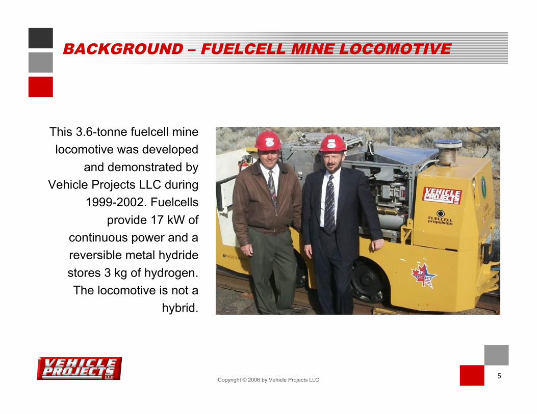
This 3.6-tonne fuelcell mine
locomotive was developed
and demonstrated by
Vehicle Projects LLC during
1999-2002. Fuelcells
provide 17 kW of
continuous power and a
reversible metal hydride
stores 3 kg of hydrogen.
The locomotive is not a
hybrid.
6Copyright © 2006 by Vehicle Projects LLC
BACKGROUND – FUELCELL MINE LOADER
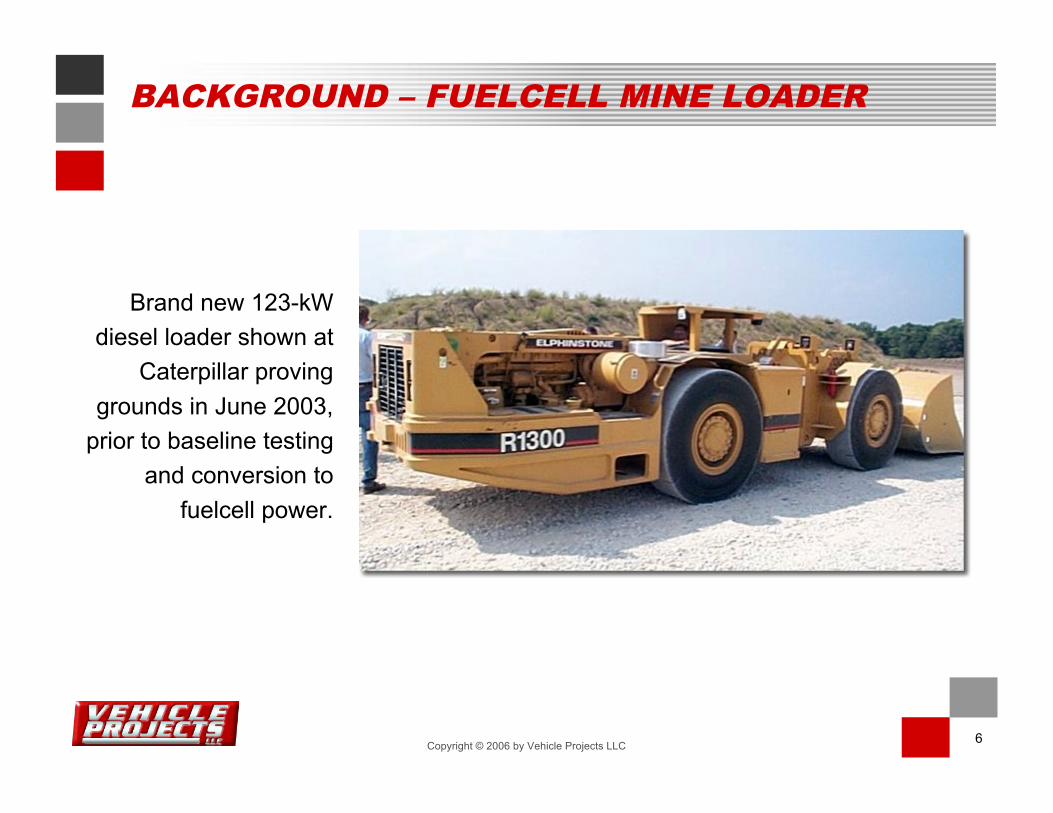
Brand new 123-kW
diesel loader shown at
Caterpillar proving
grounds in June 2003,
prior to baseline testing
and conversion to
fuelcell power.

7Copyright © 2006 by Vehicle Projects LLC
FUELCELL HYBRID POWERPLANT
160-kW fuelcell-battery hybrid
powerplant: Three fuelcell
stacks provide nominally 90
kW of continuous power; a 12-
kWh nickel metal-hydride
battery provides additional 70
kW of transient power and
absorbs energy during
regenerative braking.
With covers in place
With covers removed

8Copyright © 2006 by Vehicle Projects LLC
METAL-HYDRIDE STORAGE
Hydrogen fuel is stored as
a reversible metal hydride,
a safe and compact
method of storing hydrogen
as a solid. Photo shows
half of the hydride storage
system, the vehicle’s fuel
tank, being lowered into
the loader. The vehicle can
be refueled in 10-15
minutes.

9Copyright © 2006 by Vehicle Projects LLC
ASSEMBLY OF LOADER
The left half of the hydride-
storage unit sits in front of
the powerplant (labeled
“High Voltage”). The storage
units may be refueled in situ
or after removal from the
vehicle.

10Copyright © 2006 by Vehicle Projects LLC
Led by Vehicle Projects LLC,
a government-industry
consortium is developing a
127-tonne fuelcell-battery
hybrid switcher locomotive
with 250 kW of prime-mover
power. The vehicle will look
virtually identical to the diesel-
battery hybrid switcher at
right, one of four Green
Goats™ owned by the US
Army.Photo courtesy of RailPower Technologies
FUELCELL HYBRID SWITCHER LOCOMOTIVE
11Copyright © 2006 by Vehicle Projects LLC
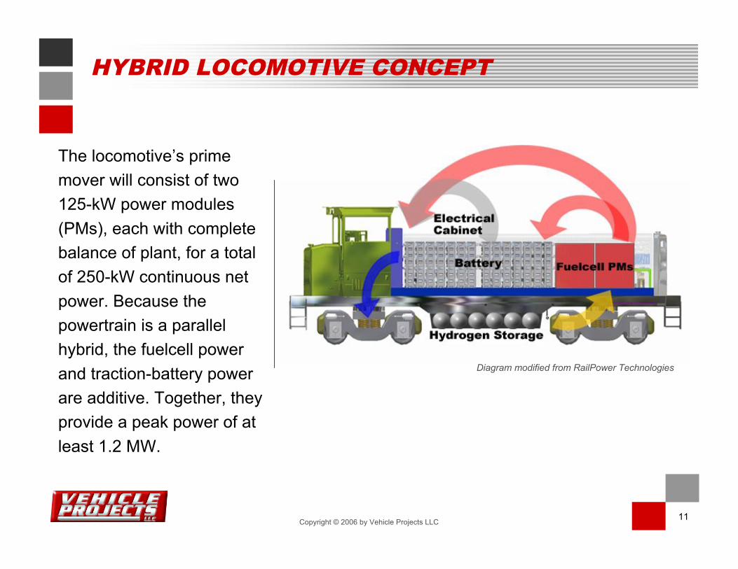
The locomotive’s prime
mover will consist of two
125-kW power modules
(PMs), each with complete
balance of plant, for a total
of 250-kW continuous net
power. Because the
powertrain is a parallel
hybrid, the fuelcell power
and traction-battery power
are additive. Together, they
provide a peak power of at
least 1.2 MW.
Diagram modified from RailPower Technologies
HYBRID LOCOMOTIVE CONCEPT

12Copyright © 2006 by Vehicle Projects LLC
Power
modulePower
Module
WEG HEX WEG HEX
Hydrogen
PM
Mounting
H2 System
Mounting
Battery Pack
600V
DC
600-850VDC
600VDC
HEX
Mounting
Loco aux
72VDC
24VDC
Start Up
BATTER
Y
Traction Motor
Blower
208VAC
Traction Motor
Blower
208VAC
coolant coolant
RailPower
Display
Fuel cell
Display
ISOLATED DC/DC
CONVERTER
coolant
Ele
ctr
ical
Cabin
et
600-850VDC
Tractionmotors (4)
TOTAL VEHICLE SYSTEM DIAGRAM

13Copyright © 2006 by Vehicle Projects LLC
Vehicle integration will
take place at the
BNSF Topeka Rail
Shop. The completed
chassis is being
loaded onto a flatcar
for transfer to
RailPower
Technologies for
addition of the body
shell, traction battery,
and vehicle controls.
BNSF TOPEKA RAIL SHOP

14Copyright © 2006 by Vehicle Projects LLC
LIMITS OF HYDROGEN VOLUMETRIC DENSITIES
99 g! = .79 g/mL, (T = 25 C)Methanolb
110 g! = 0.62 g/mL, (P = 7.2 bar, T = 15 C)Liquid Ammonia
125 g! = 8.3 g/mL, wt % = 1.5, 10 barMetal Hydride (AB5, LaNi5)
70 g! = .070 g/mL (P = 1 bar, T = bp)Liquid H2
25 g340 bar (5,000 psi)Gaseous H2
H2 MassConditions of StorageFuel Occupying 1 La
a Fuel only – container and processor excluded
b Requires water also: CH3OH + H2O ! 3H2 + CO2. In principle, water can be obtained from thefuelcell.

15Copyright © 2006 by Vehicle Projects LLC
System envelope
System Envelope Volume = 0.38 m3
Hydrogen Mass = 3.15 kg (340 bar)
Hydrogen Density = 8.29 kg/m3
System Envelope Volume = 0.38 m3
Hydrogen Mass = 7.0 kg (10 bar)
Hydrogen Density = 18.4 kg/m3
Compressed gasMetal hydride
PRACTICAL HYDROGEN VOLUMETRIC DENSITIES
16Copyright © 2006 by Vehicle Projects LLC
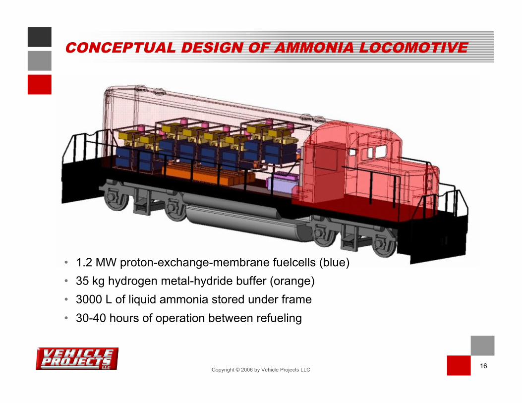
CONCEPTUAL DESIGN OF AMMONIA LOCOMOTIVE
• 1.2 MW proton-exchange-membrane fuelcells (blue)
• 35 kg hydrogen metal-hydride buffer (orange)
• 3000 L of liquid ammonia stored under frame
• 30-40 hours of operation between refueling
17Copyright © 2006 by Vehicle Projects LLC
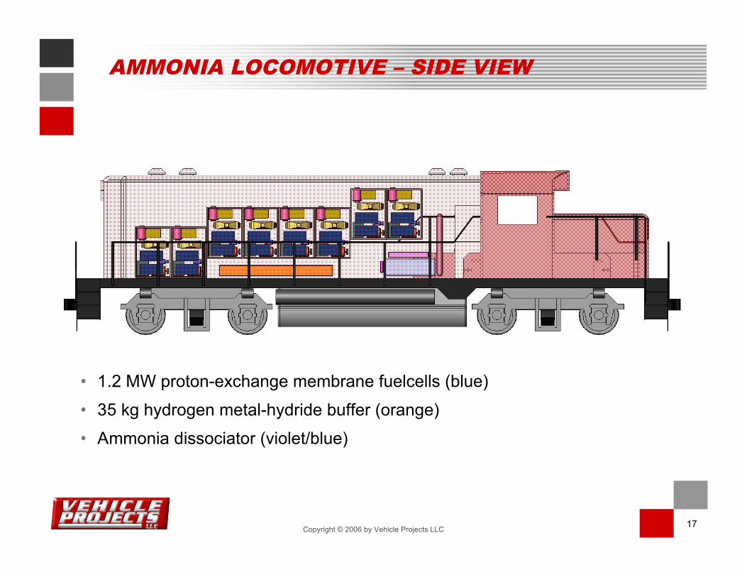
• 1.2 MW proton-exchange membrane fuelcells (blue)
• 35 kg hydrogen metal-hydride buffer (orange)
• Ammonia dissociator (violet/blue)
AMMONIA LOCOMOTIVE – SIDE VIEW

18Copyright © 2006 by Vehicle Projects LLC
PROCESS DIAGRAM FOR AMMONIA FUELCELL LOCOMOTIVE*
Ammonia Storage Tank
Adsorbent
Columns
Fuel
Cell
Stack
Re
acto
r
Co
mb
usto
r
N2, H
2O
Air
Air
N2, O
2,
& H2O
1 MWe
* From “Ammonia-Based Hydrogen Production for the Proposed Fuel-Cell Locomotive,” MesoFuel Inc, Albuquerque, NM, study
commissioned by Vehicle Projects LLC, Denver, CO, December 2003

19Copyright © 2006 by Vehicle Projects LLC
VOLUME OF SYSTEM COMPONENTS
NHNH33 TankTank
5300 L5300 L
Reactor &Reactor &
CombustorCombustor
400 L400 LHeatHeat
ExchangersExchangers
50 L50 L
AdsorbentAdsorbent
SystemSystem
150 L150 L
PipingPiping
& BOP& BOP
60 L60 L
Total = 5960 LTotal = 5960 L

20Copyright © 2006 by Vehicle Projects LLC
PROCESS FLOW DIAGRAM FOR AMMONIA DECOMPOSITION
25C 600C
Counterflow HXReactor/
Combustor
365 SCCM
Anhydrous NH3
75% H2
25% N2
1000 ppm NH3
Temperature
Fuel/Air Mixture
Combustion
Gas7 W
8W
14W
(100-W scaled unit)

21Copyright © 2006 by Vehicle Projects LLC
AMMONIA AS FUEL
• Produced on a massive scale (> 140 million tons/y)
• Mainly transported by rail car
• Pressure-temperature characteristics similar to
propane
• Classified as nonflammable but strong tissue irritant
• Detectible by odor at safe concentrations
• 17% hydrogen by weight and cleanly cracked
• Economical source of hydrogen ($1.70/kg H2)

22Copyright © 2006 by Vehicle Projects LLC
BENEFITS OF AMMONIA FUEL
• Renewable fuel – produced from hydrogen and
atmospheric nitrogen
• Zero emissions – water and nitrogen
• Energy-dense liquid capable of fueling line-haul freight
trains and high-speed rail

23Copyright © 2006 by Vehicle Projects LLC
FINANCIAL SUPPORT
US Department of Energy, Hydrogen Program
US Department of Energy, Office of Industrial Technologies
Government of Canada, Action Plan 2000 on Climate Change
Natural Resources Canada, Emerging Technologies Program
US Department of Defense, US Army National Automotive Center
Government of Japan, Railway Technical Research Institute
Fuelcell Propulsion Institute
BNSF Railway Company
Corporate cost-share contributors