amos iii - igvc.org
TRANSCRIPT
AMOS I I I
Team Members:
Harry Chan-maestas, James Letendre, Alan Meekins, Brian Rosenberger,
Zachery Shivers, Patrick Vidal, Josh Watts, Ziyan Zhou
Faculty Statement:
I hereby certify that the design and development of the robot discussed in this technical report
has involved significant contributions by the aforementioned team members, consistent with the
effort required in a senior design course.
________________________________________________
Dr. Ferat Sahin
Department of Electrical Engineering
Rochester Institute of Technology

IntroductionThe Rochester Institute of Technology (RIT) Multi-Disciplinary Robotics Club (MDRC) is pleased to announce
its entry AMOS III into the 2010 Intelligent Ground Vehicle Competition. We have added several new hardware
and software innovations including distributed probabilistic mapping, a more robust E-Stop system, and...
Innovations
Distributed, Probabilistic Mapping
A distributed map system was developed to provide 3D map storage for sensor fusion. While navigating the
course, the probability of an obstacle occupying an imaginary grid surrounding the robot is is calculated and is
accumulated from different sensor models for laser range finder and line detection algorithm.
Robust, Custom E-Stop System
A robust and long-range emergency stop system was implemented in-house. The system is capable of halting
locomotion within milliseconds at distances greater than 300 feet using unlicensed 900 MHz Zigbee transceivers.
Subsystem Simplicity
Throughout this report, you will notice how each hardware subsystem strives for maximum simplicity while
maintaining robust operation. Previous competitions have shown the that simple hardware subsystems are easier
to maintain, debug, and operate while providing solid primary functionality.
Team OrganizationMDRC is a small, highly focused team of motivated students. Since our organization is multi-disciplinary, each
team member brings his own unique perspectives and talents. Our approach has been to distribute tasks to the
team members most passionate about working with or learning about them. Since each member had a vested
interest in the robot's success, they remained passionate and productive in their tasks.
To ensure that each team member's work became integrated with the collective effort, work periods were
organized in which team members were encouraged to coordinate individual efforts into their larger modules,
discuss design decisions, and to generate and receive feedback on new ideas.
Design ProcessInitial designs focus on making each system modular to allow changes from troubleshooting to any portion of the
robot without requiring additional modifications in related areas. Electronics are also arranged to keep wiring
efficient while still having easy access to individual components. Once the individual system has been debugged
to confirm its operation separately, it is tested with the rest of the robot during mock runs to test operation with
the rest of the robot and check for conflicts.
Page 2 of 14

Training
Our main method for training less experienced members is to encourage them to participate in the collaborative
work sessions we hold to design and debug the robot. While we strive to maintain thorough documentation that is
accessible to all members which makes a strong starting point, working on current issues helps provide insight on
our design and troubleshooting processes; it also gives practical experience on how individual modules operate
and interact with one another. From there, they can begin to provide their unique perspective to help overcome
obstacles as they become more acquainted with the systems.
Planning
An overall project leader provides guidance throughout the months of development leading to the competition by
setting goals and deadlines for various subsystems. A clear goal for each subsystem is stated and consequent
deadlines are set based on achieving this goal in time for testing. This year, our goals focused on simplicity in
design and robust operation under widely varied conditions.
Implementation
Once tasks are assigned to the individual or group most interested in working on it, a Trac system is used to set
milestones and assign due dates for the individual tasks. Trac is an online project management system designed to
keep software projects on target. Trac integrates with our subversion code repository and allows code check-ins to
reference tickets with progress reports as work is being done. This makes it easy to make sure all tasks are
progressing as planned, and to add man power to tasks which are falling behind.
Testing and Integration
The AMOS platform has undergone rigorous testing from individual hardware and software components, up to
full navigation system testing. All algorithms were first tested within the Player/Stage robotic simulation
environment to assess their reliability.
Testing was performed throughout the building stage. This allowed each new subsystem to be tested when it
reached a point of minimal functionality. Once any bugs found were worked out, more features were added and
subsequently tested in the same manner. This helps to reduce testing and debugging time by helping bugs to be
found early in the development cycle and minimizing the number of changes that could have caused the bug.
Once all systems were tested and verified to be functioning correctly, system testing was performed to ensure all
the modules function correctly with one another.
Mechanical Design
Modularity
The upper frame was specifically designed with modularity in mind: the upper layers can be easily reconfigured
for different purposes. For example, if the payload was to increase in height, we would only have to unscrew 4
bolts and move it up a few inches on the graduated support poles. The lower chassis was designed with a slightly
Page 3 of 14

more rigid framework in mind as the components from the motor layer are rarely changed.
The LIDAR mount is also modular in that it can be moved vertically and tilted with simple tools. We have used
this ability to tweak the trade-off between range (by adjusting the angle) and angular resolution at small distances
(by adjusting height).
The upper and lower layers have the ability to be separated, which greatly facilitates transportation in vehicles.
The only connection between the lower motor layer and the above layers is a USB cable which is electrically
isolated to provide noise immunity. The benefit of minimizing interfaces between these layers is that it allows
simple physical disconnection as well as an abstracted, reusable motor layer for other projects.
Ruggedness
The AMOS chassis was custom built directly to accommodate our design needs. It is made of a steel rebar with
diagonal elements to reduce flexing and it includes slots specifically for our batteries and motors. Despite heavy
rain, rough terrain, and extensive test runs, the platform has remained solid and functional for several years.
Electrical Design
Power system
The power subsystem is extremely simple and self-contained by design: it consists only of four batteries, a relay
for the E-Stop, and two switches controlling the computer and motor layer power. All battery charging is done off-
board; this ensures we can quickly swap out batteries with freshly charged ones. All batteries are enclosed in the
motor layer, pushing the center of gravity down towards the ground. Each battery is a Genesis 12V 12Ah.
Computer system
Maximizing computing performance was crucial for a highly responsive system. As our AMOS platform expands
and matures, many design requirements need to be fulfilled for the present and future systems. The table below
summarizes the design criteria for the main computer:
Requirement Satisfied By Advantage Disadvantage
High performance
CPU
Intel Core 2 Quad
Q8200
-Excellent performance,
multiple cores.
-Facilitates multi-threaded
nature of Player/Stage
- Comparatively high power
consumption
High speed
memory access
4 GB of DDR2
SDRAM (in four
separate sticks)
- Fills all four motherboard
RAM slots, allowing max
simultaneous memory
access
- None
Page 4 of 14

Requirement Satisfied By Advantage Disadvantage
More than one
USB bus
Motherboard with 3
USB buses
-High I/O count
motherboard
-Meets USB requirements
-Form factor is within
shelving space
-Comparatively expensive
motherboard
Shock and
vibration
resistance
32 GB Solid state drive -Unaffected by heavy
vibration and shock
-Extremely fast read and
write speeds compared to
conventional hard drive
- Much higher cost per GB
than conventional hard drives
High efficiency
power conversion
High efficiency 250W
DC-to-DC converter
-Small
-No need to convert from
AC back to DC within the
supply
- None
Additionally, a laptop is connected to the top layer of the robot to act as a debug terminal. This debug terminal can
be used to see data in real-time to help track down and fix errors as well as initialize initialize the robot through
Player/Stage.
Emergency stop system
A completely new and custom emergency stop
system was built for AMOS this year; it was
designed with reliability and safety in mind.
The complete E-stop system consists of a remote
(handheld) unit and a local (robot) unit. Both local
and remote modules utilize the ATMega168
microcontroller and a XBee-PRO 900 radio
modem. The remote is powered by a rechargeable
battery which will last approximately 4 hours with
continuous use, while the local module is powered
by the 12V power-rail from the robot's power
system. Both units have a pair of LEDs for
monitoring current state and error conditions.
Page 5 of 14
Figure 1: Emergency stop module 3D mockup

When turned on, the remote unit immediately begins
broadcasting the state of the E-Stop button several times
per second at 115200 baud. Upon receiving these
broadcasts, the robot checks the CRC provided by the
XBee to ensure a complete message. If the message
passes the CRC check, it notes the current time and
checks the contents of the message. If the message
contains the "STOP" command, or no valid message has
been received for more than the 2.1 times the inter-
broadcast delay, the robot will immediately disable the
motors, bringing AMOS to a halt. Once halted, the robot
will not re-enable itself until it has received the "GO"
signal for more than 5 consecutive seconds without error.
In the previous year's implementation we used standard XBee-PRO modules which worked well around our
college campus, but failed on the competition grounds due to high interference from the multitude of 2.4 GHz
spectrum devices. After evaluating last year's failure, we identified several key features that must be present in
this year's choice of radio-modem. The XBee-PRO 900 meets every one of our design requirements:
Goal Xbee-PRO 900
Operates in a non 2.4GHz spectrum - Operates in the 900MHz ISM band, out of the crowded Wi-Fi
frequency range
Provides good resistance to nearby
signals and EMI
- Frequency-hopping Spread-spectrum (FHSS) algorithm allows a more
powerful transmitter due to limited use of individual frequencies
- Reasonable level of protection against noise in specific frequencies
Reliable data-transport - API includes a checksum for all transmitted and received data,
allowing the local module to trust every bit in the received message
Motor controller
An in-house motor controller was created to abstract the low-level control of the robot's movement. The controller
uses a closed loop, velocity-based PID controller with high resolution optical encoders on both wheels providing
feedback.
Experience has shown that high resolution encoders provide much smoother PID control when properly tuned.
Low speeds can cause problems with low resolution encoders due to lack of data while the robot is slowly rolling.
Page 6 of 14
Figure 2: Block diagram of emergency stop system

Our new encoder selection offers very high precision:
Direct Angular Resolution 180 ticks / revolution
Linear Resolution ~1500 ticks / wheel revolution
or 62 micron / tick
Though much of the linear precision is lost due to slippage on the terrain or slack in the motor assembly, the high
angular resolution is still directly beneficial for our control system.
The motor controller is based on the Arduino Diecimila (with the ATMega328 microcontroller running at 20
MHz). This controller was chosen due to its widespread commercial availability and open source support. The
GCC toolchain - which includes a C compiler and other valuable tools - provided easy setup and integration
process.
The motor-controller board has a custom PCB attached to it which provides a point of connection for the PWM
signal to the motors, the signals from the encoders, and the measurements from the power monitoring circuit.
Instead of using the Arduino's built-in USB to serial UART, the attached PCB includes it's own USB to serial
UART which is optically isolated from the rest of the Arduino and motor-layer. Power for the UART and USB
side of the optical isolator is derived from the USB port, while the Arduino powers the non-USB side of the
isolator. This provides over a kilovolt of protection between the computer and the base layer and blocks any back-
EMF noise induced by the motors from reaching the computer.
The motor controller is command by the main computer via serial data stream. Velocity commands are constantly
issued by the computer as well as requests for encoder data. If the controller does not receive any velocity
commands for greater than 500 milliseconds, it immediately halts locomotion. This is a safety feature designed to
keep the robot from losing control if USB cable is somehow disconnected.
Sensors
LIDAR
For near-field obstacle detection and avoidance we make use a Light Detecting and Ranging module, made by
SICK. A spinning mirror inside the device directs the laser over a 360 degree path (180 of which actually visible
through the device's shield). At each finite degree, the distance the laser travels is measured and the angle plus
distance is returned as part of a sweep. This is done many times per second to produce a horizontal line of points
out to a distance of a meter or two.
dGPS
For absolute positioning, AMOS uses a differential GPS made by Trimble. It receives signals from the standard
Page 7 of 14

GPS satellites, as well as differential corrections from ground towers and satellites. Using the differential
corrections, the AgGPS132 can achieve sub-meter accuracy anywhere in the continental United States.
Compass
To steer towards specific GPS waypoints, AMOS uses a digital compass from Robotics Connection. The CMPS03
is an I2C peripheral which provides the current heading in tenths of degrees.
Webcams
AMOS is outfitted with three commercial USB webcams. This three camera setup utilizes one high quality
webcam, to provide detailed frontal images for use in mapping, and two lower cost cameras to provide peripheral
vision. The peripheral cameras can be used to detect dangerous situations that are out side of the field of view of
both the LIDAR and the primary imagery.
Current/Voltage
The motor controller uses a combination voltage/current sensor to monitor for exceptional conditions of the
motors. Current is software limited per motor to 20 amperes. Voltage sensing also provides a method of testing if
the robot's E-stop system is activated.
Encoders
High resolution optical encoders provide quadrature angular velocity measurements of the shaft of each motor.
Quadrature capabilities quadruple our resolution as well as give the direction of spinning.
Software Design
Overview
AMOS software uses the open source player robotics framework. Player has a server/client architecture, allowing
algorithms and different components of the software to run on different machines and processes. Player robotics
also dramatically the reuse ability of software code since a set of standard abstract hardware and software
interfaces are defined.
A small number of built-in player drivers are utilized in AMOS software to interface with common hardware,
including:
• sicklms200 - communication interface for the SICK LIDAR 2D range finder
• camerauvc - frame grabber from USB video camera
• camerav4l - frame grabber using the video4linux system
• garminnmea - driver for DGPS receiver
• festival - interface for voice synthesis to provide status announcement
Page 8 of 14
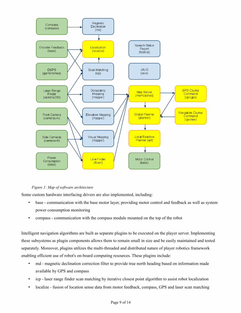
Some custom hardware interfacing drivers are also implemented, including:
• base - communication with the base motor layer, providing motor control and feedback as well as system
power consumption monitoring
• compass - communication with the compass module mounted on the top of the robot
Intelligent navigation algorithms are built as separate plugins to be executed on the player server. Implementing
these subsystems as plugin components allows them to remain small in size and be easily maintained and tested
separately. Moreover, plugins utilizes the multi-threaded and distributed nature of player robotics framework
enabling efficient use of robot's on-board computing resources. These plugins include:
• md - magnetic declination correction filter to provide true north heading based on information made
available by GPS and compass
• icp - laser range finder scan matching by iterative closest point algorithm to assist robot localization
• localize - fusion of location sense data from motor feedback, compass, GPS and laser scan matching
Page 9 of 14
Figure 1: Map of software architecture

Plugins continued:
• mapper - sensor fusion mapping plugin to map ground elevation, visual data and occupancy probability
• cspace - plugin to automatically create and update configuration space map based on the occupancy
probability map
• planner - global planner using A* search algorithm to find optimal path on configuration space map given
current location and goal
• igvcgps - command unit for IGVC GPS course challenge, solves traveling salesmen problem
continuously to determine the order of visit for waypoints based on the latest information available on the
map
• lfcam - line finder vision algorithm to identify lines from camera frame
• igvcnav - command unit for IGVC autonomous navigation challenge
The map server is implemented using the fast and distributed memcached server. It provides simultaneous read
and write access to the multi-channel map for all components that utilizes the map. The map itself is formated in
tiles and can be stored into and loaded from a sqlite3 database.
Localization
Precise localization is very difficult based on any single source of pose information. To minimize the errors in
using encoders for position sensing, compass and GPS data are combined to make a correction. The encoders
keep track of an (x, y) offset from the initial position as well as an offset angle. When updates from the compass
are received, the error in the angle is calculated, and used for future updates. When a new GPS position is
received, the encoder position offset by the error in the angle is calculated, and then the x and y errors are
calculated. Between updates from the compass and GPS the encoders are corrected by first rotating by the angle
error, and then by translating it by the x and y error. This scheme provides corrections for any wheel slipping.
Mapping
Map Server
A distributed map system is developed to provide 3D map storage for sensor fusion. This new mapping system
divides the grid map into small tiles of user defined size. Each tile only gets created and stored when data for such
tile is modified. The map can grow without boundary in all directions and remains efficient in using storage space.
Each map also has multiple channels allowing probability data, configuration space data, visual data and elevation
data to be stored separately for each cell.
Page 10 of 14

The map system uses memcached, a high-
performance, distributed memory object
caching system, to provide super fast transfer
of tile data with low delay. Client library is
provided for multiple components of the robot
software system to read and write the shared
map simultaneously. The client library also
takes care of tile loading, locking, and saving,
hiding away the internal tile structure from
end programmers. And finally, the map that
lives on the memcached server during robot
operation can be saved onto a harddisk in the
sqlite3 database format. These databases can
be loaded back into the memcached server if
continue exploration of the same area is desired.
Occupancy Probability
The probability of occupancy for each cell is calculated and accumulated from different sensor models for laser
range finder and line detection algorithm. A probability of 0.5 representing unknown spaced is assumed for new
map cells. When this probability will gradually grow to near 1.0 as the evidence of obstacles within the cell
accumulates. On the other hand, free space accumulates towards a probability of 0.0.
Configuration Space
Configuration space map is generated and
continuously updated by a process that
monitors the probability map for changes.
Obstacles are grown in size by the maximum
radius of the robot, such that robot is
represented as a single point of mass in the
configuration space. This dimensionless
representation of the robot simplifies path
planning by eliminating the need to consider
the physical size of the robot when
determining whether a path is feasible. Buffer
zones are also created near all obstacles. These
areas are intentionally marked with higher
costs depending on its distance from the closest obstacle. Buffer zones provides a guidance for the path planning
Page 11 of 14
Figure 3: Configuration space map. Red regions are fully traversable,
blue shades indicate undesirable traversability scores
Figure 2: 2D Visualization of map data. Red areas indicate no obstacles,
blue and green indicate increasing probability of obstacles

algorithm to avoid being too close to any obstacle while not prohibiting such path if it is truly necessary.
Visualizer
Along with the mapping system, a visualizer is
developed to render the different channels of a map
in 3D. The visualizer uses OpenGL and physical
graphic card support to provide fast render of
massive amount of sensor data collected in the map.
The visualizer is a great tool for analyzing
previously recorded map. But it is an even more
vital debugging tool for displaying various data in
real time. While the robot is in operation, the
visualizer shows the location of the robot in the
changing environment as well as the path planning
decision it is making.
Global Path Planning
Global path planning is achieved using a combination of A* search algorithm and the concorde traveling salesman
problem solver. A* search algorithm provides the optimal path and cost between two given points on our
probability map. Concorde TSP solver focus on computing the optimal order of waypoints to be visited. The
system re-plans the path based on the latest information available in the map.
The A* algorithm is computed using the probability map to determine to cost of each cell..
where c = new cumulative cost and c' = cumulative cost to parent.
Local Path Planning
For more reactive path planning, a potential field approach is used. This approach allows input from various
sensors to be accumulated easily. The algorithm uses obstacles to repel the robot from them, while the robot has a
Page 12 of 14
Figure 4: 3D visualization of the probabilistic obstacle map

desire to drive forward, or toward a GPS waypoint. The robot will drive close to the mid-point between obstacles
because this is the point of equilibrium in the current view. The local path planning allows the robot to react to
obstacles not yet present on the map which are missed by the global planner. It also allows the robot to react to a
changing environment.
Visual Lane Detection
When a frame is acquired the image is converted to the normalized RGB color space. This transformation helps
reduce the effect of changing lighting conditions. Next color segmentation is used to select areas in the image
which are closest to the expected color of the white lines. The above color distance image shows the result of
measuring the error for all pixels to the expected color value. The dark regions are close to the desired color while
lighter areas have colors which are far from the desired value. A threshold is applied to the distance image and
tested against the model of white lines. The model will only select masked areas which are narrow enough to
possibly be white line segments. The location of the masked areas are projected into the the robot's coordinate
frame and are then passed to the local planner as the coordinates of obstacles which must be avoided.
Step 1: Input imageStep 2: Normalized RGB
Step 3: Color “distance”. Step 4: Thresholded final image of lane lines
Page 13 of 14

JAUS Compliance
We use Jr. Middleware's open source implementation of JAUS SAE-AS4 standards in a custom Player driver and
device proxy to realize JAUS compliance. The Player driver and device proxy break down JAUS communication
into a simple API and signaling process to minimize the amount of processing code required.
Conclusion
Performance Analysis
Attribute Design Goal Final Product
Speed 5 mph 4.5 mph
Reaction Time Near Instantaneous 100 ms
Battery Life 2 Hours (normal operation) 2 Hours
Obstacle detection distance 8 meters 8 meters
Vehicle performance with obstacles No collisionsNo collisions under normal
circumstances
Navigation point accuracy 0.2 meter 1 meter
Bill of Materials
Page 14 of 14
Category Part Part No QtyChassis Frame materials (steel) Metal Supermarket - 30 Ft $100 $100 $100
Frame materials (alum) Metal Supermarket - 15 Ft $75 $75 $75Misc. hardware Various - - - $75 $75Misc. elec. connectors Various - - - $40 $40Motors Unknown - 2 $500 $1,000 $0
Sensors LIDAR SICK LMS-291 1 $5,000 $5,000 $0dGPS Trimble AgGPS132 1 $500 $500 $0Digital compass Robotics Connection CMPS03 1 $57 $57 $57Optical encoders US Digital E8P 2 $38 $76 $76Front webcam Logitech QuickCam Pro 9000 1 $80 $80 $0Side webcams Lego Legocam 2 $30 $60 $0
Computer Motherboard Newegg N82E16813128358 1 $135 $135 $135CPU Newegg N82E16819115055 1 $169 $169 $169Memory Newegg N82E16820231144 2 $32 $64 $64DC-DC power supply Minibox M4-ATX 1 $90 $90 $90
E-Stop XBee-PRO 900 Digi XBP09-DPSIT-156 2 $45 $90 $90ATMega168 Atmel ATMEGA1284P-PU 2 $8 $16 $16Emergency Stop Switch Omron A165E-S-01 1 $41 $41 $41
Batteries Genesis 12V 12Ah Genesis G12V26AH10EP 4 $120 $480 $480Totals: $7627 $987
Manufacturer / Vendor
Unit Cost (Market)
Subtotal (Market)
Unit Cost (Actual)