ampair pacific 300 wind turbine manual - reps · date: 02 feb 2011 ampair ® 300 (mk1,...
TRANSCRIPT
Date: 02 Feb 2011 Ampair ® 300 (Mk1, “Pacific”) Wind Turbine Manual CD 2300
Issue: 1.2 Page 1 of 34
- 1 - © Ampair, April 2007
Ampair ®
300 Wind Turbine
Operation & Maintenance Manual

Date: 02 Feb 2011 Ampair ® 300 (Mk1, “Pacific”) Wind Turbine Manual CD 2300
Issue: 1.2 Page 2 of 34
- 2 - © Ampair, April 2007
1 INTRODUCTION .................................................................................................................................... 3
1.1 Labelling ........................................................................................................................................... 3
1.2 Applications ...................................................................................................................................... 3
2 SAFETY INSTRUCTIONS ..................................................................................................................... 4
2.1 Disclaimer: ........................................................................................................................................ 4
2.2 Potential sources of danger .............................................................................................................. 4
3 TECHNICAL CHARACTERISTICS ........................................................................................................ 7
3.1 Required space ................................................................................................................................ 7
3.2 Technical data .................................................................................................................................. 7
3.3 System description ........................................................................................................................... 8
4 INSTALLATION ...................................................................................................................................... 9
4.1 Installation sequence ........................................................................................................................ 9
4.2 Wind turbine packing list................................................................................................................. 10
4.3 Accessories packing lists................................................................................................................ 11
4.4 Tools ............................................................................................................................................... 12
4.5 Choosing a mounting...................................................................................................................... 13
4.6 Electrical installation ....................................................................................................................... 16
4.7 Electrical components .................................................................................................................... 19
4.8 Final assembly ................................................................................................................................ 23
5 OPERATION & PERFORMANCE ........................................................................................................ 25
5.1 Starting and stopping...................................................................................................................... 25
5.2 Performance ................................................................................................................................... 26
6 INSPECTION & MAINTENANCE ......................................................................................................... 27
6.1 Major disassembly .......................................................................................................................... 27
6.2 Drawings and component list ......................................................................................................... 31
6.3 Recommended spares ................................................................................................................... 33
7 WARRANTY ......................................................................................................................................... 33
8 SERVICING, REPAIRS, & DISPOSAL ................................................................................................ 33
Disclaimer:
The information in this manual is believed to be correct and reliable. However Ampair assumes no responsibility for inaccuracies and omissions. The user of this information and product assumes full responsibility and risk.
All specifications are subject to change without notice.
Wind turbines, electrical power and battery systems, and wind turbine mounting systems are all capable of causing death or serious injury or fire if incorrectly installed, operated, or maintained. If in doubt, ensure that all activities are carried out by trained and competent personnel.

Date: 02 Feb 2011 Ampair ® 300 (Mk1, “Pacific”) Wind Turbine Manual CD 2300
Issue: 1.2 Page 3 of 34
- 3 - © Ampair, April 2007
1 INTRODUCTION Thank you for purchasing an Ampair 300 wind turbine.
Ampair has been producing high quality wind turbines for over thirty years. The Pacific 300 is designed and manufactured to give you many years of trouble free power generation. However, as with any other wind turbine, reliable and effective operation will depend on where it is located and how it is assembled and connected. Periodic inspection and maintenance is required. Furthermore there are safety hazards associated with all wind turbines and this is why we ask that you read this manual carefully.
1.1 Labelling This manual applies to the Ampair 300 manufactured by Ampair.
Ampair Energy Ltd
Unit 2 Milborne Business Centre, Blandford Hill
Milborne St Andrew, BLandford Forum, Dorset, DT11 0HZ
UK
Tel. +44 (0)1258 837 266
Fax. +44 (0)1258 837 496
Internet www.ampair.com
Email [email protected]
Ampair™ is a business of Boost Energy Systems Ltd, manufacturers of distributed energy systems for fifty years. Ampair™ and PowerFurl™ are trademarks of Ampair and Boost Energy Systems Ltd.
The label with the model type and nominal voltage is on the electrical box cover where the name Ampair is shortened to AMPAIR.
The serial number of the wind turbine is stamped on the lower left side of the main body casting on the outside of the tail fin flange.
1.2 Applications The electrical power produced by the Pacific 300 wind turbine charges 12 volt or 24 volt DC batteries. Alternating current (AC) electrical appliances can be supplied by connecting a 220/240 volt or 110 volt inverter to the batteries.
For over thirty years wind turbines manufactured by Ampair have powered a wide variety of locations including sailing yachts; remote houses; medical facilities; holiday homes; emergency shelters; navigational aids; scientific and environmental monitoring stations; telecommunications systems; cathodic protection systems; remote industrial locations; caravans and mobile homes; and increasingly are being used to decrease dependence on centrally generated electricity in grid-connected homes, offices, and commercial property.
Date: 02 Feb 2011 Ampair ® 300 (Mk1, “Pacific”) Wind Turbine Manual CD 2300
Issue: 1.2 Page 4 of 34
- 4 - © Ampair, April 2007
Ampair recommends that most clients install wind turbines in combination with a proportionate amount of solar photovoltaic panels (solar PV) as wind and solar power are highly complementary sources of renewable, carbon neutral, non-polluting energy.
2 SAFETY INSTRUCTIONS Please read this manual carefully before starting assembly and installation, or before conducting maintenance. This manual provides information that is critical to ensuring your safety during assembly, operation, and in case of trouble. If you have further questions please contact your dealer, an Ampair service partner, or Ampair itself.
2.1 Disclaimer:
The information in this manual is believed to be correct and reliable. However Ampair assumes no responsibility for inaccuracies and omissions. The user of this information and product assumes full responsibility and risk.
All specifications are subject to change without notice.
Wind turbines, electrical power and battery systems, and wind turbine mounting systems are all capable of causing death or serious injury or fire if incorrectly installed, operated, or maintained. If in doubt, ensure that all activities are carried out by trained and competent personnel.
2.2 Potential sources of danger Wind turbines are electrical machines with high speed rotating parts which are typically mounted at height. Thus there are a variety of sources of potential hazards which can result in death or serious injury. These dangers exist during installation, operation, or inspection and maintenance.
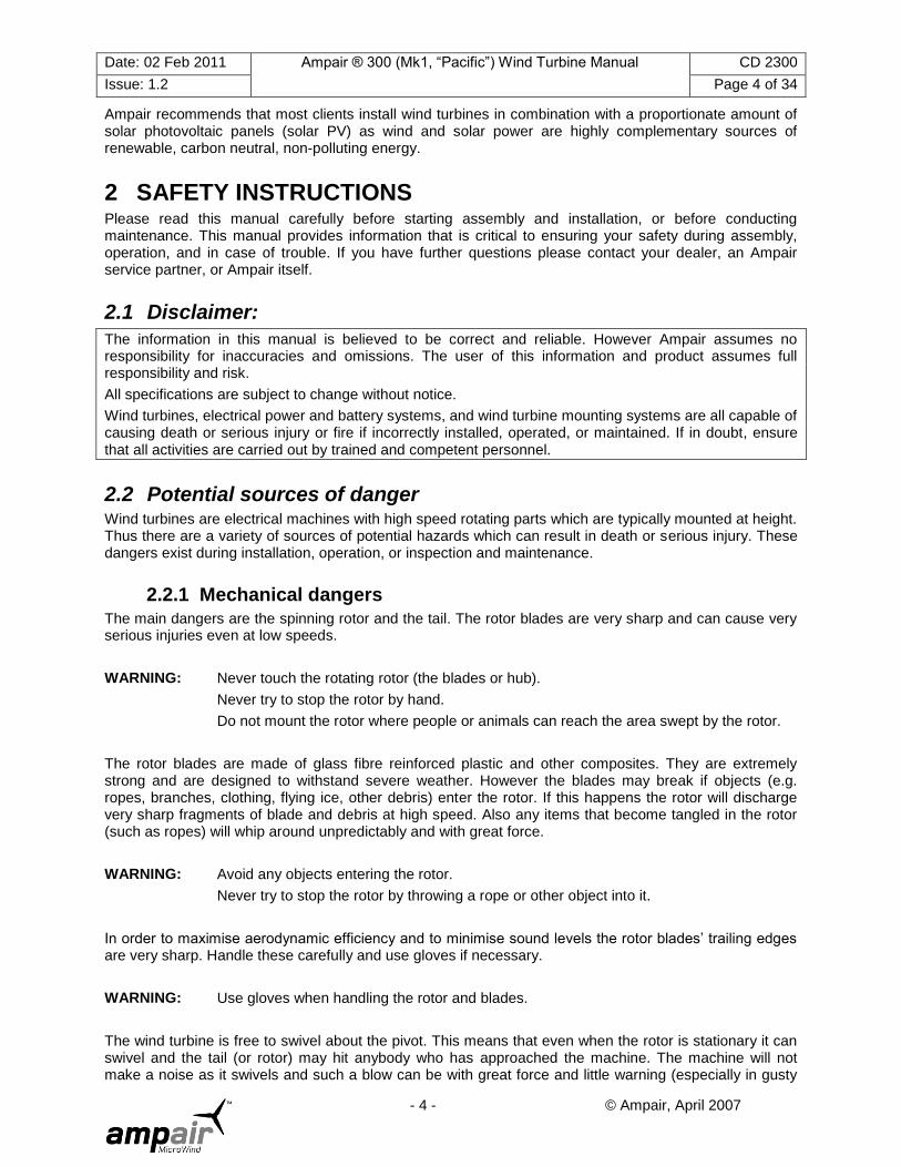
2.2.1 Mechanical dangers
The main dangers are the spinning rotor and the tail. The rotor blades are very sharp and can cause very serious injuries even at low speeds.
WARNING: Never touch the rotating rotor (the blades or hub).
Never try to stop the rotor by hand.
Do not mount the rotor where people or animals can reach the area swept by the rotor.
The rotor blades are made of glass fibre reinforced plastic and other composites. They are extremely strong and are designed to withstand severe weather. However the blades may break if objects (e.g. ropes, branches, clothing, flying ice, other debris) enter the rotor. If this happens the rotor will discharge very sharp fragments of blade and debris at high speed. Also any items that become tangled in the rotor (such as ropes) will whip around unpredictably and with great force.
WARNING: Avoid any objects entering the rotor.
Never try to stop the rotor by throwing a rope or other object into it.
In order to maximise aerodynamic efficiency and to minimise sound levels the rotor blades‟ trailing edges are very sharp. Handle these carefully and use gloves if necessary.
WARNING: Use gloves when handling the rotor and blades.
The wind turbine is free to swivel about the pivot. This means that even when the rotor is stationary it can swivel and the tail (or rotor) may hit anybody who has approached the machine. The machine will not make a noise as it swivels and such a blow can be with great force and little warning (especially in gusty
Date: 02 Feb 2011 Ampair ® 300 (Mk1, “Pacific”) Wind Turbine Manual CD 2300
Issue: 1.2 Page 5 of 34
- 5 - © Ampair, April 2007
wind conditions and/or on a boat). It will swivel extremely unpredictably if the rotor is fitted but the tail is not fitted.
WARNING: Prevent the machine swivelling before entering the radius of the tail and rotor.
Wear a safety helmet before entering the radius of the tail and rotor.
2.2.2 Electrical dangers
The generator can produce open circuit voltages of up to 60 volts ACrms (12 volt version) and 120 volts ACrms (24 volt version) in the wiring run between the turbine and rectifier. This is in no load operation with the stop switch in the „on‟ position and at a wind speed of approximately 30 miles per hour (approximately 15 metres per second).
WARNING: Avoid handling bare open circuit wiring tails unless the rotor is physically stopped.
The charging current can reach up to 25 amps DC (12 volt version) and 12.5 amps DC (24 volt version) in the wiring run between the rectifier and the battery (or load).
WARNING: Install cables with sufficient cross sectional area of conductor. Inadequately sized cables can rapidly overheat and create a fire hazard.
Install electrical components of sufficient voltage and current capacity at all points in the circuit.
The battery must never be short circuited as the fault current is extremely high. If you do so there is a serious risk that you will set the battery and cabling on fire, as well as releasing flammable and potentially explosive gases (hydrogen) from the battery, and you will probably destroy the battery.
WARNING: Never short circuit the battery.
Install fuses immediately adjacent to the wind turbine side of the battery (but not within the battery compartment as the spark from a blowing fuse could ignite an explosive hydrogen/air mixture).
Charging lead acid batteries releases flammable and potentially explosive hydrogen gas. Unsealed lead acid batteries have vent caps to release this gas, which can detonate if it is mixed with air and a spark is present (e.g. from a switch or a blowing fuse) or other ignition source (e.g. naked flame or hot surface such as an exhaust).
WARNING: Provide sufficient ventilation to the battery compartment.
Do not locate ignition sources within the battery compartment.
The regulators manufactured by Ampair are charge control regulators. However if you have chosen to install (perhaps) cheaper and (definitely) less effective dump regulators then you should be aware that these can become very hot. They must not be mounted on flammable surfaces.
WARNING: Do not install dump regulators on or near flammable materials.
2.2.3 Dangers when mounting the wind turbine or working at height
Very careful attention must be given to the strength and integrity of the mounting. As a minimum this should be capable of withstanding a peak horizontal load of 50 kg (100 lbs). If mounting the wind turbine
Date: 02 Feb 2011 Ampair ® 300 (Mk1, “Pacific”) Wind Turbine Manual CD 2300
Issue: 1.2 Page 6 of 34
- 6 - © Ampair, April 2007
on a boat, note that the mounting has to withstand both the thrust from the wind, as well as the weight of the turbine, and the inertial loads arising from vessel motions.
WARNING: Only use adequately designed mounting systems.
A fall from the height at which a wind turbine is ordinarily mounted will often result in death or serious injury. Therefore whenever practicable carry out as much work as possible on the wind turbine at deck or ground level. If it is necessary to work on an installed wind turbine then use an appropriate access system such as a mast that is designed to carry the load of a person; a „man-rated‟ winch or rope access system; a hydraulic lift or other safe working platform. Wear appropriate safety equipment and make the general working area as a tidy and safe as possible. If possible work during daylight on windless days (and in calm seas if on a boat). Above all else think carefully about what you need to do and plan your work carefully, have all the tools and equipment ready before you start, then brief all the members of the work team thoroughly – including the actions in the event of an accident and/or injury.
WARNING: Whenever possible work on the ground or deck, not at a height.
Use safety harnesses, safety helmets, and safety slings, etc.
Use „man-rated‟ lifting equipment and access systems
Work in daylight, on windless days (and in calm seas).
Keep the work area clear, plan your work, have your entire equipment ready, and brief the team before starting the job.
Falling objects are potentially fatal. Do not step underneath hanging loads or folding/tilted masts. Make sure that onlookers are kept back beyond the collapse radius of any masts. Ensure that any suspended objects or tools are secured (e.g. by safety lanyards). Prevent onlookers from approaching (e.g. erect a safety barrier and warning signs).
WARNING: Secure any objects that might fall.
Do not go underneath hanging loads and the work area; wear safety helmets.
Keep onlookers at a safe distance.
When working on the wind turbine, especially when working at height, it is important to make sure it is first electrically safe. Therefore prevent it generating (use the stop switch, turn it out of wind, and/or tie one of the rotor blades to the mounting system or mast) and disconnect it from the battery system.
WARNING: Disconnect all batteries and other power sources.
Prevent the generator from unintended starting.
Never approach the running rotor.

Date: 02 Feb 2011 Ampair ® 300 (Mk1, “Pacific”) Wind Turbine Manual CD 2300
Issue: 1.2 Page 7 of 34
- 7 - © Ampair, April 2007
3 TECHNICAL CHARACTERISTICS
3.1 Required space The Pacific 300 is designed for installation on 2" and 3" mounting systems. The diagram below shows the external dimensions in millimetres (mm):
3.2 Technical data Nominal power 300 Watts
Rated wind speed for nominal power 12.6 metres per second
(25 knots, or 29 miles per hour)
Cut in wind speed 3 metres per second
(6 knots, or 6.9 miles per hour)
Thermal cut out None
Survival wind speed Storm proof
Rotor diameter 1.2 metre
Number of blades 3
Blade material Glass reinforced polyester (GRP)
Date: 02 Feb 2011 Ampair ® 300 (Mk1, “Pacific”) Wind Turbine Manual CD 2300
Issue: 1.2 Page 8 of 34
- 8 - © Ampair, April 2007
Rotor speed 500-1400 rpm
Generator type Permanent magnet, three phase with external rectifier
(rare earth neodymium magnets)
Nominal voltage 12 volt DC or 24 volt DC
Speed regulation Blade pitch control above 13 metres per second
(27 knots, 30 miles per hour)
Power regulation Blade pitch control above 13 metres per second
Brake Generator short circuit (optional 'stop' switch)
Weight 12 kg
Housing Die cast aluminium (powder coated)
Colour White with red hub (other colours available on request)
Rotor thrust (at 20 metres per second) 160 Newtons
3.3 System description The Ampair 300 is a wind driven generator (a wind turbine) capable of supplying up to 300 Watts of electrical power at either 12 or 24 volts for charging batteries. A complete system includes the generator, the rectifier, the field wiring, and normally a stop switch and a regulator, plus of course batteries and a mounting.
3.3.1 The generator The unit consists of a two part cast aluminium body, the two parts sealed by an "O" ring. One twelve pole permanent magnet rotor runs on a stainless steel shaft. The shaft runs in two sealed grease-packed ball bearings. One three phase stator is located within the body.
The three phase alternating current output of the stator passes to three carbon brushes mounted in brush holders located behind the lower body section, accessible through the electrical cover plate. The carbon brushes carry the output to three brass slip rings mounted on the stationary pivot shaft, allowing the machine to rotate to follow the wind. The output is electrically isolated from the case.
The body is mounted on the pivot shaft where it runs on sealed grease packed ball bearings at the top and a composite plain bearing at the base. The top bearing is captive in the body; the lower bearing is located in the body by a stainless steel spiral retaining ring. The pivot section contains an "O" ring around the lower bearing to body junction and a "V" seal where the pivot shaft passes through the lower bearing.
The pivot axis passes through the centre of gravity of the assembled machine. This is necessary to ensure alignment into the wind in light breezes without undue spinning, and to allow the wind turbine to be used on small boats.
The rotor disc and hub together make up the unique PowerFurl™ furling mechanism. The three cambered and twisted glass reinforced polyester (GRP) moulded blades have been designed to be perfectly balanced and aerodynamically and acoustically efficient. They are mounted on an aluminium hub (shaped like a nose cone). The purpose of the PowerFurl™ furling mechanism is to simultaneously twist all three blades along their axis when the wind speed becomes excessive, whilst still keeping the wind turbine facing into the wind and generating power. The three special pitching weights form an integral part of the PowerFurl™ mechanism. The hub is fitted to the generator shaft by an M10 cap screw.
The blades have a relatively broad root section to enable them to start up in low wind speeds. This is important as for much of the time the wind only blows at low speeds. The blades are of a rigid construction to minimise pulsating aerodynamic noise caused by blade deflection (fluttering)
An aluminium alloy tail vane is clamped to the rear of the generator body using three M8 x 25mm stainless steel screws, six plain washers and three lock nuts. The tail vane is provided with a grab hole at its lower corner to facilitate turning the unit cross-wind to stop the wind turbine rotating when required (e.g. using a boat hook).
All Ampair 300 units are constructed of marine grade materials. All aluminium parts are alacromed and powder coated inside and out, or anodised. All other parts are stainless steel or composite, except for elastomers.

Date: 02 Feb 2011 Ampair ® 300 (Mk1, “Pacific”) Wind Turbine Manual CD 2300
Issue: 1.2 Page 9 of 34
- 9 - © Ampair, April 2007
3.3.1.1 Low temperature operation Plastic materials do not perform well in extreme cold, becoming brittle and breaking. This applies to wind turbine blades, whether glass filled or not. Operation at around 0°C should not be a problem, but most materials are vulnerable at –20°C and cannot be warranted to survive indefinitely. Ampair‟s glass filled polyester blades are superior to nylon, carbon polymer or other plastics in this respect. However, when ice factors are also considered, the prediction of blade reliability is even more difficult.
Other materials are also suspect. For this reason Ampair uses Neoprene components where possible and "Arctic" grade PVC cables. Grease used in sealed bearings allows performance to –30°C or below, but component tolerances (ball and ring) can lead to greater friction and increased wear causing reduced bearing life.
3.3.2 The rectifier It is best to transmit electrical power as AC at as high a voltage and as low a current as possible so as to minimise losses due to the resistance of the wiring system. For this reason the rectifier of the Pacific 300 is not fitted inside the generator but is instead supplied as a separate unit for fitting adjacent to the regulator and or battery. The rectifier is a three way bridge rectifier mounted on a heat sink.
3.3.3 Other system components The basic wind turbine package only consists of the generator and rectifier. The other components which can be linked together in a modular manner are described elsewhere in this manual.
4 INSTALLATION
4.1 Installation sequence A lot of problems can be prevented if the following sequence is adhered to:
1. First check that your order is complete and undamaged, and that you have received the correct voltage generator (12 or 24 volt). See the packing lists below to assist in this.
2. Gather your tool kit. See tool list below.
3. Plan your installation. See guidance notes below.
4. Mechanically install the mounting system.
5. Run the electrical wiring and mechanically mount any accessories (including the rectifiers on their heatsink) but do not connect to the batteries.
6. Mechanically install the wind turbine generator, and then electrically connect it.
7. Connect to the batteries.
8. Check correct operation & installation.

Date: 02 Feb 2011 Ampair ® 300 (Mk1, “Pacific”) Wind Turbine Manual CD 2300
Issue: 1.2 Page 10 of 34
- 10 - © Ampair, April 2007
4.2 Wind turbine packing list The Pacific 300 Wind Turbine is packaged in recyclable cardboard cartons. The cartons contain:

Date: 02 Feb 2011 Ampair ® 300 (Mk1, “Pacific”) Wind Turbine Manual CD 2300
Issue: 1.2 Page 11 of 34
- 11 - © Ampair, April 2007
A 1 pcs Generator and hub
B 1 pcs Tail fin
C 1 pcs Operation manual
D 1 pcs Tail fin pad
E 9 pcs Tail fin mounting nuts and washers
F 6 pcs Turbine blade mounting nuts and washers
G 6 pcs Blade mounting bolts M6 × 30 Hex Bolts
H 3 pcs Tail fin mounting bolts (no pad) M8 × 25 Bolts
I 3 pcs Tail fin mounting bolts (with pad) M8 × 35 Bolts
J 2 pcs Allen keys 5mm and 6mm
K 3 pcs Rotor blade
4.3 Accessories packing lists
4.3.1 Basic Pacific 300 stern mount kit (SMK)
The basic Ampair 300 Stern Mount Kit (SMK) carton contains:
A 1 pcs Pole A, 800mm, Four 6.5mm holes each end, two 10.2mm holes centrally
B 1 pcs Pole B, 800mm, Four 6.5mm holes each end.
C 1 pcs Pole C, 970mm, 25mm OD, strut pole,
D 2 pcs Stay wires Terminated by thimbles and "D" ring nuts.
E 1 pcs Bag 1 Containing: yoke, two angle feet and backstay clamp shell.
F 1 pcs Bag 2 Containing: one anodised aluminium alloy joiner tubes.
G 1 pcs Kit 1: Strut, yoke & feet fixings
1 pcs M6 x 40mm screw
2 pcs M6 x 35 hex screw
3 pcs M6 shakeproof washers
3 pcs M6 Nyloc nuts
1 pcs M10 threaded rod 75mm
2 pcs M10 shakeproof washers
1 pcs M8 x 60mm hex bolt
2 pcs M8 plain washers
1 pcs M8 Nyloc nut
H 1 pcs Kit 2: Joiner tube fixings 16 pcs M6 x 10mm screws
16 pcs M6 shakeproof washers
This arrangement, places the blade tips 2 metres (7 feet) above the base fixing. If there is a raised area adjacent upon which people may stand, raise this base accordingly.
4.3.2 Pacific 300 mizzen bracket
The Ampair 300 Mizzen Bracket carton contains:
O 1 pcs Bracket
P 2 pcs threaded rod Ml0 x 150mm threaded rod

Date: 02 Feb 2011 Ampair ® 300 (Mk1, “Pacific”) Wind Turbine Manual CD 2300
Issue: 1.2 Page 12 of 34
- 12 - © Ampair, April 2007
Q 8 pcs Nuts MI0 nuts
R 8 pcs plain washers Ml0 plain washers
4 pcs Shakeproof washers MI0 shakeproof washers
4.3.3 Pacific 300 gantry mount
The Ampair 300 Gantry Mount carton contains:
O 1 pcs Bracket Pole with double welded base flange
4.3.4 Pacific 100 to Pacific 300 mounting adaptor
The Ampair 100 to Pacific 300 mounting adaptor bag contains:
O 1 pcs Adaptor tube Pole with female to male cross-over
4.3.5 Pacific 300 land mounting systems Mounting systems are available for land use of the Ampair 300, but most users choose to fabricate their own from local materials. See guidance notes further on, or ask Ampair if you wish to purchase a system suitable for your site.
4.3.6 Pacific 300 basic regulator The Ampair 300 Basic Regulator comes in two versions: the 12 volt or the 24 volt version. It is not possible to convert these from one to the other. The carton contains:
A 1 pcs Regulator 12 volt or 24 volt version
B 1 pcs Operation manual
4.3.7 Pacific 300 advanced regulator
The Ampair 300 Advanced Regulator comes in only one version which can be configured for either 12 volt or 24 volt use (by Ampair authorised dealers). The carton contains:
A 1 pcs Regulator Configurable
B 1 pcs Operation manual
4.3.8 Pacific 300 stop (parking) switch
The Ampair 300 Stop Switch carton contains:
A 1 pcs Stop (parking) switch
B 1 pcs Operation manual
4.3.9 Fuse holder and fuses The bag of fuse holders and fuses contains:
A 1 pcs Fuse holder For 30 Amp, slow blow
B 1 pcs Fuse 30 Amp, slow blow
4.4 Tools For installation of your Ampair 300 the necessary Allen keys are supplied. In addition to any specialist tools required for locally fabricated mounting systems, the following general tools will also be helpful:
Screw drivers
Spanners
Wire strippers

Date: 02 Feb 2011 Ampair ® 300 (Mk1, “Pacific”) Wind Turbine Manual CD 2300
Issue: 1.2 Page 13 of 34
- 13 - © Ampair, April 2007
Wire crimpers
Heat shrink and/or electrical tape
Multimeter
4.5 Choosing a mounting Where and how to mount a wind turbine is critical. The consequences of selecting a poor location can be unsafe operation, poor reliability, and low power output – or all three. As well as reading these guidance notes, if in doubt please consult Ampair or your distributor for advice.
4.5.1 Siting land based units
The wind turbine should be sited as high as practicable, clear of windbreaks or buildings and away from sources of turbulence. These conditions are shown diagrammatically below.
WARNING: Before a wind turbine is installed in an excessively windy location, the operators must satisfy themselves that the site is suitable. It may be necessary to log site wind speed and direction data at various heights prior to installing the machine.
Any indication of turbulence means that the generator should be re-sited or raised above the turbulence. Wind data must be from exactly where the turbine is to be sited, not merely close by.
If possible avoid roof-top mounting which can give rise to turbulence, shock loads and vibration. If roof-top mounting is selected then ask Ampair for a vibration-isolated mounting system.
4.5.2 Mechanical installation of land based units Free-standing installations should generally conform to the figure on the right. The main components are:

Date: 02 Feb 2011 Ampair ® 300 (Mk1, “Pacific”) Wind Turbine Manual CD 2300
Issue: 1.2 Page 14 of 34
- 14 - © Ampair, April 2007
Mast: of steel tube (water pipe or scaffold tube), alloy
tube or wood (telegraph pole). If the guys are unsuitable (grazing cattle or small children) then use a telegraph pole one third buried, or a lattice tower as an expensive alternative.
Guys: Usually galvanised steel wire protected by
plastic sheath and fitted with end thimbles. Don‟t use a material that will stretch or deteriorate. Three equally spaced guys (120°) will assist raising and lowering the assembled mast. A high mast will require intermediary guying: the top guys hold the mast upright, and the lower guys prevent it from buckling.
The top fixing point for the guys should allow for minimum overhang of the wind turbine generator, i.e. be only a short distance below the wind turbine blade tips. This prevents the top section of the mast from swaying too much.
Tensioners: These are the simple and easiest method of tensioning guys, but adjustment must be
uniform, since it is the guys that resist the thrust of the wind turbine. Do not over tension – a guy should be snugly taut, but not drum tight.
Ground anchors: These should be suitable eyebolts fixed
in the ground and in line with the guys. Anchors in soft earth may require concrete blocks or „dead men‟. Gravel or clay soils require “auger” type anchors (see inset picture) and rocky ground may need drilling and expanding rock anchors. Only the eye should be visible above ground. Avoid waterlogged soils which have poor holding properties. Install anchor below the frost level or otherwise „frost heave‟ will eject them.
Base: This is to carry the weight of the generator and mast
only. Fixing again depends on the ground state but metal pegs driven into soil are often sufficient. A lattice tower would need a concrete base with expansion bolt fixings („rawlbolts‟). It is often convenient to make a pivot arrangement for the base in-line with one guy anchor to aid raising and lowering.
Lightning: Directly earth all metalwork. Bury output cables (minimum ½ metre depth) between mast
and battery position for better protection than suspending in air. Either run cabling through plastic conduit or use a type specified for burying by local building or electrical codes.
4.5.3 Siting boat based units
There are four basic alternatives in the confined quarters of most small boats:
a) On a tall stayed pole on the stern of a boat (either the basic or the de luxe stern mount kit).
b) On a bracket on the mizzen mast of a yacht (mizzen bracket).
c) On a custom made welded „pushpit‟ structure, "A" frame, davit gantry etc. (gantry mount).
d) At the main or mizzen masthead of a yacht.
Date: 02 Feb 2011 Ampair ® 300 (Mk1, “Pacific”) Wind Turbine Manual CD 2300
Issue: 1.2 Page 15 of 34
- 15 - © Ampair, April 2007
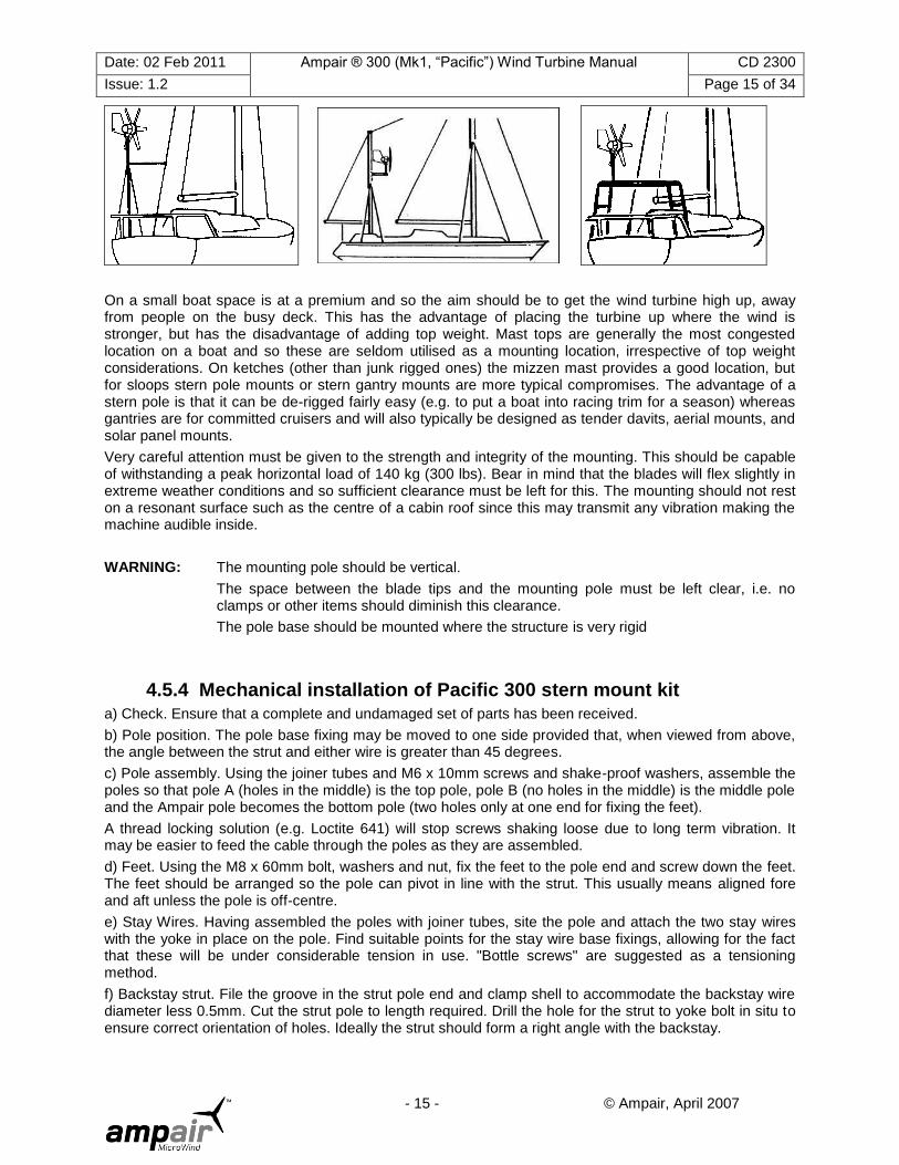
On a small boat space is at a premium and so the aim should be to get the wind turbine high up, away from people on the busy deck. This has the advantage of placing the turbine up where the wind is stronger, but has the disadvantage of adding top weight. Mast tops are generally the most congested location on a boat and so these are seldom utilised as a mounting location, irrespective of top weight considerations. On ketches (other than junk rigged ones) the mizzen mast provides a good location, but for sloops stern pole mounts or stern gantry mounts are more typical compromises. The advantage of a stern pole is that it can be de-rigged fairly easy (e.g. to put a boat into racing trim for a season) whereas gantries are for committed cruisers and will also typically be designed as tender davits, aerial mounts, and solar panel mounts.
Very careful attention must be given to the strength and integrity of the mounting. This should be capable of withstanding a peak horizontal load of 140 kg (300 lbs). Bear in mind that the blades will flex slightly in extreme weather conditions and so sufficient clearance must be left for this. The mounting should not rest on a resonant surface such as the centre of a cabin roof since this may transmit any vibration making the machine audible inside.
WARNING: The mounting pole should be vertical.
The space between the blade tips and the mounting pole must be left clear, i.e. no clamps or other items should diminish this clearance.
The pole base should be mounted where the structure is very rigid
4.5.4 Mechanical installation of Pacific 300 stern mount kit
a) Check. Ensure that a complete and undamaged set of parts has been received.
b) Pole position. The pole base fixing may be moved to one side provided that, when viewed from above, the angle between the strut and either wire is greater than 45 degrees.
c) Pole assembly. Using the joiner tubes and M6 x 10mm screws and shake-proof washers, assemble the poles so that pole A (holes in the middle) is the top pole, pole B (no holes in the middle) is the middle pole and the Ampair pole becomes the bottom pole (two holes only at one end for fixing the feet).
A thread locking solution (e.g. Loctite 641) will stop screws shaking loose due to long term vibration. It may be easier to feed the cable through the poles as they are assembled.
d) Feet. Using the M8 x 60mm bolt, washers and nut, fix the feet to the pole end and screw down the feet. The feet should be arranged so the pole can pivot in line with the strut. This usually means aligned fore and aft unless the pole is off-centre.
e) Stay Wires. Having assembled the poles with joiner tubes, site the pole and attach the two stay wires with the yoke in place on the pole. Find suitable points for the stay wire base fixings, allowing for the fact that these will be under considerable tension in use. "Bottle screws" are suggested as a tensioning method.
f) Backstay strut. File the groove in the strut pole end and clamp shell to accommodate the backstay wire diameter less 0.5mm. Cut the strut pole to length required. Drill the hole for the strut to yoke bolt in situ to ensure correct orientation of holes. Ideally the strut should form a right angle with the backstay.
Date: 02 Feb 2011 Ampair ® 300 (Mk1, “Pacific”) Wind Turbine Manual CD 2300
Issue: 1.2 Page 16 of 34
- 16 - © Ampair, April 2007
4.5.5 Mechanical installation of Pacific 300 mizzen bracket
The major load that the bracket has to withstand is one of torsion, hence the box section. At 100mm wide this is close to the width of many mizzen masts and any slight difference can be accommodated by bending the end plates to suit or by spacing with nuts and washers.
Drill through the end plates and mizzen and fit using the M10 fixings provided. Monel rivets are the best attachment method for aluminium masts. Studs are best for wooden masts. If using studs on aluminium masts then fit spacers so as not to crush the mast.
If there is any danger of running rigging becoming entangled in the wind turbine then install stays to keep the turbine guarded.
4.6 Electrical installation Electrical installation should only be performed by competent personnel who have studied this manual. If in doubt ask Ampair.
First mechanically mount the main system components (except the wind turbine), then run the field cabling, then make the connections, then install the wind turbine and connect to it. Only then connect to the battery.
WARNING: Do not assemble the generator, vane and turbine until the electrical installation is completed
4.6.1 Wiring diagrams
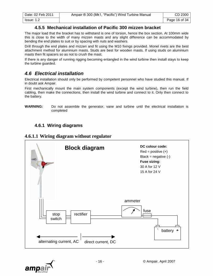
4.6.1.1 Wiring diagram without regulator
rectifier
battery + -
stop switch
fuse
ammeter
DC colour code:
Red = positive (+)
Black = negative (-)
Fuse sizing:
30 A for 12 V
15 A for 24 V
Block diagram
alternating current, AC direct current, DC
Date: 02 Feb 2011 Ampair ® 300 (Mk1, “Pacific”) Wind Turbine Manual CD 2300
Issue: 1.2 Page 17 of 34
- 17 - © Ampair, April 2007
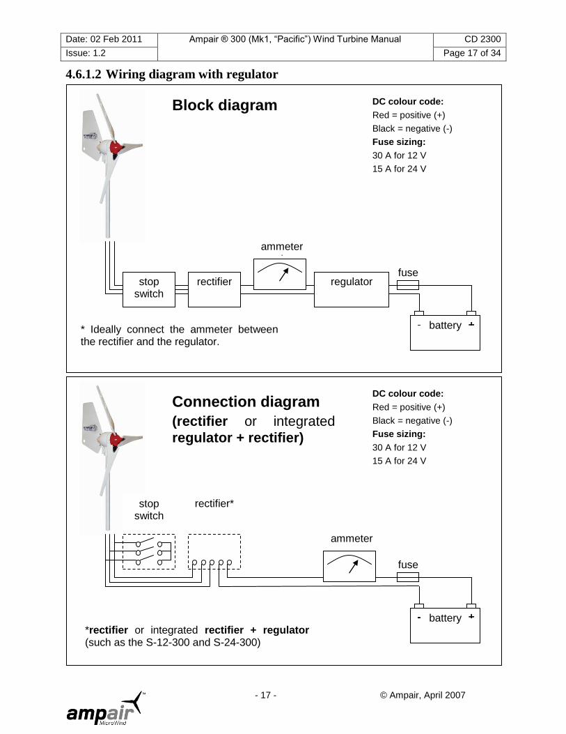
4.6.1.2 Wiring diagram with regulator
battery + -
fuse
ammeter
DC colour code:
Red = positive (+)
Black = negative (-)
Fuse sizing:
30 A for 12 V
15 A for 24 V
stop switch
rectifier*
*rectifier or integrated rectifier + regulator (such as the S-12-300 and S-24-300)
Connection diagram
(rectifier or integrated
regulator + rectifier)
battery + -
rectifier
fuse stop
switch
ammeter*
DC colour code:
Red = positive (+)
Black = negative (-)
Fuse sizing:
30 A for 12 V
15 A for 24 V
regulator
Block diagram
* Ideally connect the ammeter between the rectifier and the regulator.

Date: 02 Feb 2011 Ampair ® 300 (Mk1, “Pacific”) Wind Turbine Manual CD 2300
Issue: 1.2 Page 18 of 34
- 18 - © Ampair, April 2007
battery + -
fuses
DC colour code:
Red = positive (+)
Black = negative (-)
Fuse sizing:
30 A for 12 V
15A for 24 V
stop switch
rectifier / heat sink
*separate rectifier and regulator such as NC25A used in single in / single out configuration
Connection diagram
(separate regulator and
rectifier)
ammeter bat+
regulator
in+
sense
- sense+
battery + -
fuse
DC colour code:
Red = positive (+)
Black = negative (-)
Fuse sizing:
30 A for 12 V
15A for 24 V
stop switch
rectifier / heat sink
*separate rectifier and regulator such as PR-300 used in single in / single out configuration
Connection diagram
(separate regulator and
rectifier)
regulator
gen1+
gen2+
gen- bat-
bat2+
bat1+
ammeter

Date: 02 Feb 2011 Ampair ® 300 (Mk1, “Pacific”) Wind Turbine Manual CD 2300
Issue: 1.2 Page 19 of 34
- 19 - © Ampair, April 2007
If the Pacific 300 wind turbine is connected on the load side of the battery isolator switch, it may damage electrical equipment. Under these conditions it is possible to run the wind turbine whilst the battery is isolated, but this can subject the system to excess voltage.
WARNING: Connect the wind turbine to batteries, not to loads.
4.7 Electrical components
4.7.1 Wiring After deciding where the wind turbine is to be mounted measure the length of the wiring that will actually run to the battery in both the AC section (the three wire section from the turbine to the rectifier) and the DC section (the two wire section from the rectifier to the battery). Then select the minimum cross sectional area per cable from the table below. Wherever possible locate the rectifier as close to the battery so as to minimise the DC cable length and to maximise the AC cable length.
Minimum AC cable size for 12 volt wind turbine:
Total AC section length Up to 8 m
Up to 27 ft
8 to 12 m
27 to 40 ft
12 to 18 m
40 to 60 ft
18 to 30 m
60 to 100 ft
30 to 50 m
100 to 166 ft
30 to 76 m
166 to 253 ft
76 to 100 m
253 to 333 ft
Minimum cross sectional area per cable
2.5 mm2
14 AWG
4 mm2
12 AWG
6 mm2
10 AWG
10 mm2
8 AWG
16 mm2
6 AWG
25 mm2
4 AWG
35 mm2
2 AWG
Minimum DC cable size for 12 volt wind turbine:
Total DC section length Up to 5 m
Up to 16 ft
5 to 10 m
16 to 32 ft
10 to 18 m
32 to 60 ft
18 to 28 m
60 to 90 ft
28 to 44 m
90 to 145 ft
44 to 68 m
145 to 220 ft
68 to 110 m
220 to 360 ft
Minimum cross sectional area per cable
4 mm2
12 AWG
6 mm2
10 AWG
10 mm2
8 AWG
16 mm2
6 AWG
25 mm2
4 AWG
35 mm2
2 AWG
50 mm2
1 AWG
Minimum AC cable size for 24 volt wind turbine:
Total AC section length Up to 8 m
Up to 27 ft
8 to 12 m
27 to 40 ft
12 to 18 m
40 to 60 ft
18 to 30 m
60 to 100 ft
30 to 50 m
100 to 166 ft
30 to 76 m
166 to 253 ft
76 to 100 m
253 to 333 ft
Minimum cross sectional area per cable
1.5 mm2
16 AWG
2.5 mm2
14 AWG
4 mm2
12 AWG
6 mm2
10 AWG
10 mm2
8 AWG
16 mm2
6 AWG
25 mm2
4 AWG
Minimum DC cable size for 24 volt wind turbine:
Total DC section length Up to 5 m
Up to 16 ft
5 to 10 m
16 to 32 ft
10 to 18 m
32 to 60 ft
18 to 28 m
60 to 90 ft
28 to 44 m
90 to 145 ft
44 to 68 m
145 to 220 ft
68 to 110 m
220 to 360 ft
Minimum cross sectional area per cable
2.5 mm2
14 AWG
2.5 mm2
14 AWG
4 mm2
12 AWG
6 mm2
10 AWG
10 mm2
8 AWG
16 mm2
6 AWG
25 mm2
4 AWG
WARNING: Insufficient cross sectional area of conductor will cause the cable to heat up and create a fire hazard all along the cable, at the same time.
WARNING: Always use tinned stranded conductors for best corrosion protection on boats.
WARNING: Connect with the correct polarity. When wiring the DC system be aware that if the wind turbine is connected to the battery by the reverse polarity the output rectifiers may be destroyed or the internal soldered connections to the brush holders may melt. Check and double-check DC polarity before final connection.
BROWN or RED = + Positive

Date: 02 Feb 2011 Ampair ® 300 (Mk1, “Pacific”) Wind Turbine Manual CD 2300
Issue: 1.2 Page 20 of 34
- 20 - © Ampair, April 2007
stop switch
Connection diagram
(stop switch)
BLUE or BLACK = - Negative (YELLOW is preferred colour in the USA)
When mounting the Ampair 300 on its mounting pole or bracket, the cable needs to be fed down through the mounting. When arranging this cable make sure it cannot chafe at the point where it leaves the mounting pole. Either lead the cable out of the bottom of the pole in a gentle curve or, drill an exit hole in the pole large enough to take a rubber grommet to protect the cable from the sharp edges of the hole.
In marine environments cables with tinned multi-strand conductors are recommended to prevent salt air corrosion which will otherwise cause substantial performance reductions in a short time.
Wiring between the generator (or junction box, connector, etc.) and the battery area should be clipped at regular intervals to the structure for safety and a neat job.
On boats, to carry power from the Ampair to internal wiring we recommend that a good quality water-tight connector be fitted
Cable hanging inside masts can be quite heavy. We recommend fitting a strain relief at the top so that the weight is not carried by the wind turbine. Arrange this strain relief so that if the cable is disconnected from the wind turbine (so as to remove the wind turbine for maintenance) then the end of the cable can be secured and not fall down inside the mast.
If there is any danger of the cable „slatting‟ noisily inside a hollow mast, then place some closed cell foam pipe insulation over it as anti-slatting collars.
Maintain a consistent colour scheme throughout the cable runs, and mark line ends with a positive (+) and negative (-) symbol to minimise risk of errors. At different times and in different countries the colour schemes used in wiring systems have varied. If reusing old cable runs the only way to be sure is to carefully trace all the cables and „loop test‟ them yourself during initial installation,
4.7.2 Fuses and circuit breakers
Fuses or miniature circuit breakers (MCBs) should always be fitted. The simplest possible arrangement feeds the power from the Ampair directly to the battery via an in-line fuse in the positive line near to the battery.
WARNING: Always install a fuse. The fuse should be next to the battery terminal since, in the event of a fault or damage to the cable, the battery will supply the fault-current.
Do not place the fuse inside the battery compartment itself as, in the event of a build up of explosive hydrogen/air mixture in the battery compartment, the spark from a blowing fuse could provide the detonation source.
4.7.3 Parking (stop) switch
We recommend installing a „stop‟ switch which should be more correctly thought of as a „parking‟ switch. Just as the parking brake in a car should not be relied on to stop a car at high speed, so the parking switch of the Ampair wind turbine should not be relied on to stop the rotor disc in high winds. Instead it is best to apply it before the arrival of very high winds, or if needing to ensure that the rotor does not move in low winds (e.g. when approaching the rotor for maintenance).
The switch should be wired as shown in the diagram above. If wired in this way the wind turbine will be stopped with the switch in the „ON‟ or „1‟ position, and will run normally with the
switch in the „OFF‟ or „0‟ position. IMPORTANT NOTE: The „stop‟ switch is only to be used for stopping the turbine in order that it can be inspected or to carry out maintenance. In the event of high winds the
Date: 02 Feb 2011 Ampair ® 300 (Mk1, “Pacific”) Wind Turbine Manual CD 2300
Issue: 1.2 Page 21 of 34
- 21 - © Ampair, April 2007
turbine should be allowed to keep running, or if possible tied to its mast– never set the ‘stop’ switch to short in these conditions as your turbine may be damaged.
4.7.4 Ammeter
We recommend installing a basic ammeter so as to monitor the performance of the system. It should be wired in series (assuming it to be of the internal shunt variety) with one line, normally the positive. This will allow the machine output to be seen at all times. As shown, the positive (+) connection of the ammeter is made to the generator, whilst the negative (-) is made to the battery. It is best to connect the ammeter in the section of cable between the rectifier and the regulator as otherwise the voltage drop across the ammeter prevents the regulator seeing the battery voltage. This point is particularly important if a poor quality ammeter is fitted. It does not apply if 'sense' wires are used.
WARNING: Never connect an ammeter across the supply.
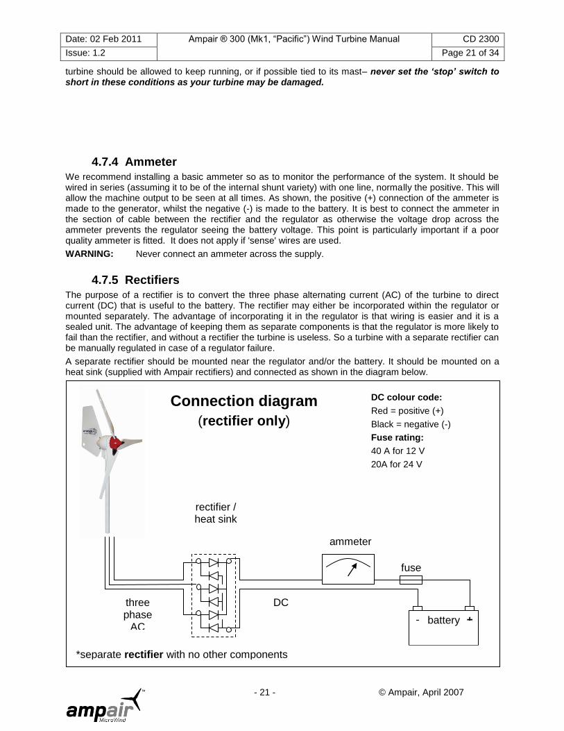
4.7.5 Rectifiers
The purpose of a rectifier is to convert the three phase alternating current (AC) of the turbine to direct current (DC) that is useful to the battery. The rectifier may either be incorporated within the regulator or mounted separately. The advantage of incorporating it in the regulator is that wiring is easier and it is a sealed unit. The advantage of keeping them as separate components is that the regulator is more likely to fail than the rectifier, and without a rectifier the turbine is useless. So a turbine with a separate rectifier can be manually regulated in case of a regulator failure.
A separate rectifier should be mounted near the regulator and/or the battery. It should be mounted on a heat sink (supplied with Ampair rectifiers) and connected as shown in the diagram below.
battery + -
fuse
ammeter
DC colour code:
Red = positive (+)
Black = negative (-)
Fuse rating:
40 A for 12 V
20A for 24 V
rectifier / heat sink
*separate rectifier with no other components
Connection diagram
(rectifier only)
three phase
AC
DC

Date: 02 Feb 2011 Ampair ® 300 (Mk1, “Pacific”) Wind Turbine Manual CD 2300
Issue: 1.2 Page 22 of 34
- 22 - © Ampair, April 2007
4.7.6 Regulators
Ampair manufactures charge control regulators for protecting lead acid batteries from overcharge. They are not "shunt" type regulators, which dissipate excess charge as heat, but an electronic power switch which disconnects the generator from the battery at the regulation voltage. When the generator is disconnected it will „freewheel‟ at a faster speed.
Three different regulators are available for the Ampair 300. The S-12-300 and the S-24-300 are encapsulated regulators with integral rectifiers. They only have one input channel and one output channel. The correct regulator must be purchased to suit the turbine and battery bank layout, i.e. 12 volt or 24 volt. No user configuration is possible of the S-12-300 or S-24-300.
The battery voltage is sensed at the regulator output connection, therefore install the regulator as near the battery as practicable and keep the connecting cables short. The regulators charging continuously until a Lo or Hi voltage is reached, depending on the battery output used. The generator is then disconnected from the battery. Off-charge the battery voltage will fall. At a voltage of 0.5V below the regulation voltage a 30-second time delay is activated. This delay prevents the regulator from oscillation (hunting) when charging batteries under load.
The PR-300 is a user configurable regulator which must be installed with a separate external rectifier. It can be configured as either a 12 volt unit or a 24 volt unit by inserting the appropriate fused links. It can also be configured to provide either two inputs (two wind turbines or a wind turbine and solar panels) or two outputs (two separate battery banks). The PR-300 regulator voltage set point can be adjusted using internal links. In the PR-300 fuses are used in other links to set 12/24 volt operation and to determine the input and output channels. The PR-300 has its own output fuse (i.e. no separate fuse is required in the battery compartment). There are status lamps on the PR-300.
4.7.6.1 Installation of regulators At initial start-up, allow a gap of 1 minute for circuit timing functions to become active.
Fuse Warning: Never omit fuses, simple in-line fuse carriers may be used, they protect your system from excessive battery currents in the event of a serious electrical fault. If they keep blowing, find out why.
The external fuses must be near to the battery terminals since, in the event of a fault, the batteries would source the fault current. Check and double-check polarities before making connections, insert the fuses in the fuse carriers last of all.
All multistage regulators are internally protected by an SAE cartridge fuse. These are not substitutes for battery protection fuses.
Corrosion: This is the enemy of all electrical connections, especially in marine environments. Site regulators in a weather proof location, as dry as possible and splash proof. Inspect all terminations and connections for signs of corrosion. Rectify by cleaning, remaking etc. Use tinned copper wire for extension leads to prevent corrosion spreading inside cable insulation.
Operating Problems: A digital multimeter is useful for checking operation/fault finding if no permanent monitoring instruments are used. Battery voltage levels and those of the charging source can be read directly. Charging current readings will require the multimeter to be installed in line. In this way currents into and out of the regulator can be observed. Do not remove battery connections since regulator operation depends on a very small supply current. If the regulator is suspect then it can be temporarily bypassed by connecting the source positive direct to a battery positive. The negative connections are common and do not need disturbing unless regulator replacement is necessary. Use the multimeter continuity range to confirm all cable runs are low resistance.
Operation: When installed, the generator and regulator will run and maintain the batteries automatically. The unit may be run in conjunction with any other charge-source with no known interactive problems. Regular battery inspection and topping up must still be carried out to obtain maximum battery life.
Faulty regulator ? If the regulator is suspect, then it can be temporarily bypassed i.e. connect the rectified output of the Ampair directly to the battery terminals observing correct polarity. If this reinstates correct charging, then the regulator must be serviced or replaced. Regulators draw a small current (typically 1mA at 12V; more on the PR-300 because of the status lamps) from the battery to activate the sense and control circuits. Without this connection the regulator will be inoperative.
Date: 02 Feb 2011 Ampair ® 300 (Mk1, “Pacific”) Wind Turbine Manual CD 2300
Issue: 1.2 Page 23 of 34
- 23 - © Ampair, April 2007
WARNING: Do not service regulators with the wind turbine running. First stop the wind turbine, then remove wires (or fuses), then service the regulator.
4.7.7 Batteries We recommend large battery banks. A minimum 300 AmpHour battery bank is advisable, and 400 or 500 AmpHours would be sensible.
4.8 Final assembly
Assemble the blades onto the generator before putting the tailfin on and then putting the entire unit on the mounting system.
CAUTION: This is the reverse of the sequence that was advised in the previous manual. The tailfin
must be put on the generator before putting the entire unit on the mounting system.
CAUTION: The blades are very sharp. Safety gloves must be worn when handling blades.
The outline process is:
1. Item checking 2. Blade mounting 3. Further steps
4.8.1 Item checking
The following items will be used during the assembly process. Check all are present before starting:
1 pcs Generator / Hub
3 pcs Rotor blade
1 pcs Blade mounting bolt kit
The blade mounting bolt kit includes:
6 pcs Blade mounting bolt M6×30 SS socket button headed capscrew
12 pcs Blade mounting washer M6 large plain washer
6 pcs Blade mounting nut M6 hex nyloc nut
1 pcs Allan key 4.0mm allan key
4.8.2 Blade Mounting
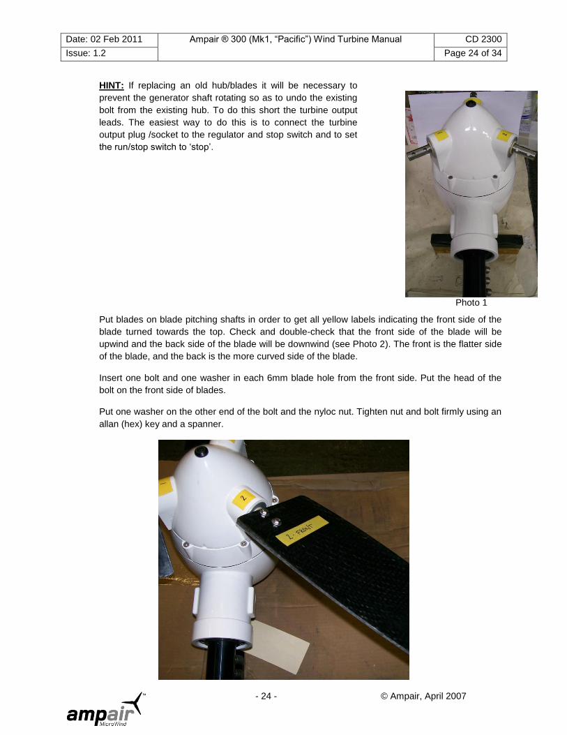
Put the generator body on a flat surface with the rear of the body down and the hub on the top. Put the hub onto the generator and rotate the hex bolt until it is firmly engaged (see Photo 1). Depending on whether you are being supplied with a new unit or whether you are replacing blades/hub on an old unit this may already have been done for you.
Date: 02 Feb 2011 Ampair ® 300 (Mk1, “Pacific”) Wind Turbine Manual CD 2300
Issue: 1.2 Page 24 of 34
- 24 - © Ampair, April 2007
HINT: If replacing an old hub/blades it will be necessary to
prevent the generator shaft rotating so as to undo the existing
bolt from the existing hub. To do this short the turbine output
leads. The easiest way to do this is to connect the turbine
output plug /socket to the regulator and stop switch and to set
the run/stop switch to „stop‟.
Put blades on blade pitching shafts in order to get all yellow labels indicating the front side of the
blade turned towards the top. Check and double-check that the front side of the blade will be
upwind and the back side of the blade will be downwind (see Photo 2). The front is the flatter side
of the blade, and the back is the more curved side of the blade.
Insert one bolt and one washer in each 6mm blade hole from the front side. Put the head of the
bolt on the front side of blades.
Put one washer on the other end of the bolt and the nyloc nut. Tighten nut and bolt firmly using an
allan (hex) key and a spanner.
Photo 1

Date: 02 Feb 2011 Ampair ® 300 (Mk1, “Pacific”) Wind Turbine Manual CD 2300
Issue: 1.2 Page 25 of 34
- 25 - © Ampair, April 2007
Photo 2
4.8.3 Further Steps a) Remove all labels
b) Clamp the tail vane using the M8 x 25mm screws washers and lock nuts.
c) Set stop switch to „stop‟.
d) Mount the Ampair. Put a thin film of grease on the pivot shaft and its fixing screw threads to prevent corrosion. Bring the Ampair body to the mounting arrangement, pass the three core cable down the mounting pole, insert the pivot shaft of the Ampair into the top and secure the fasteners. The top of the pole is made to compress the lower pivot bearing "V" seal by about 2mm - if you have made your own fixing tube, be aware of this point to ensure free turning and weather proof sealing.
WARNING: Put a rope over the Ampair passing through the blades to prevent its turning as you carry out the final checks. Once the mounting is complete, make sure all personnel are clear, turn the Ampair to face the wind and whilst holding the vane step back and remove the rope.
Check all fixings at regular intervals, especially after severe winds.
e) Connect the plug and socket of the generator electrical output and make the final electrical
connections to the battery, as shown in the electrical section. Insert the fuse or fuses in
their carriers.
5 OPERATION & PERFORMANCE
5.1 Starting and stopping Starting up. It is assumed that the wind turbine has been assembled and installed as above. If
so then remove any ropes that prevent it swivelling or the blades rotating, stand well clear, and
turn the parking / stop switch to „OFF‟ or „0‟. Provided there is sufficient wind and the turbine has
been correctly installed it will commence turning clockwise, when standing in front of the turbine
looking downwind. This direction of rotation causes the hub bolt to tighten.
Stopping. The wind turbine has been designed to survive storms, however, it is a good plan to stop the machine if a hurricane is expected or to carry out inspection. Ideally stop the wind turbine using the parking / stop switch, by turning the switch to 'ON' or '1'. If one has not been fitted then proceed with caution, approach the Ampair from downwind and grasp the tail vane (use a boathook if available). The hole in the bottom rear of the tail fin is intended to make this easier. Carefully turn the machine off wind and when the blades stop, throw a rope over them and tie down. Never throw a rope into the turning blades.
WARNING: To avoid personal injury wear sturdy gloves as a precaution. The wind turbine blades are capable of causing grave personal injury and should be treated with the same respect as an aircraft propeller.

Date: 02 Feb 2011 Ampair ® 300 (Mk1, “Pacific”) Wind Turbine Manual CD 2300
Issue: 1.2 Page 26 of 34
- 26 - © Ampair, April 2007
5.2 Performance The graph shows the output for a range of wind speeds. The drag due to the wind turbine is about 160 Newtons (16 kg / 35lbs) at 20 metres per second (40 knots) wind speed.
Power & Speed Curves
0
50
100
150
200
250
300
350
0 5 10 15 20
Wind Speed (m sec-1)
Po
we
r (W
atts)
0
400
800
1200
1600
Sp
ee
d (
RP
M)
Power
RPM
Charging Current
0
5
10
15
20
25
30
0 5 10 15 20
Wind Speed (m sec-1)
Curr
ent
(Am
ps)
0
5
10
15
20
25
30
Curr
ent
(Am
ps)Current (12 volts)
Current (24 volts)
Open Circuit Voltage
0
10
20
30
40
50
60
70
0 500 1000 1500 2000
RPM
Open C
ircuit p
d -
Volts

Date: 02 Feb 2011 Ampair ® 300 (Mk1, “Pacific”) Wind Turbine Manual CD 2300
Issue: 1.2 Page 27 of 34
- 27 - © Ampair, April 2007
6 INSPECTION & MAINTENANCE First stop the machine, see section on Stopping.
WARNING: The wind turbine blades are capable of causing grave personal injury and should be treated with the same respect as an aircraft propeller.
Put a rope over the Ampair passing through the blades to prevent its turning as you carry out the final checks. Once the mounting is complete, make sure all personnel are clear, turn the Ampair to face the wind and whilst holding the vane step back and remove the rope.
Check all fixings at regular intervals, especially after severe winds.
To avoid personal injury wear sturdy gloves as a precaution.
Regularly inspect the following:
Blade fasteners & nuts
Hub cap fixing (centre) screw
Wind turbine blades
Tail vane screws
Pole mount screws
The Ampair wind turbine generator should be inspected regularly, particularly after stormy weather, for signs of accidental damage. Any minor nicks in the edge of a blade may be filled with epoxy, but blades must be replaced if there is any sign of damage or cracking near the root. All three blades undergo very similar stresses in service and so if one blade needs replacing then all three must be replaced.
WARNING: Never allow the machine to run out of balance.
The blade material has good fatigue resistance which is of the utmost importance in hostile locations such as tropical sunshine and mountain tops. The material is, however, subject to slow degradation due to ultra violet light which increases towards the tropics and with altitude. This process is slow and when it becomes apparent as a slight crazing of the blade surface, particularly along leading and trailing edges.
The design of the blades makes the Ampair a very quiet running machine. If vibration is encountered, this is evidence that the turbine is running out of balance. To prevent any resultant noise and the risk of fixings working loose, it is most important to take action. Remove the turbine, take out the blades and examine them. If they are unbalanced and/or damaged then replace them. If they appear fine but vibration still occurs then it is possible that there is internal damage or a mounting system fault.
Any other machine noise should also be investigated. Only after very extended running life should there be any detectable bearing noise. If this is the case, refer to the maintenance section for instructions on their replacement.
The lower pivot bearing and "O" seal should be renewed after 2 - 3 years of regular use. The bearings should be replaced when they become noisy. Regularly check the security of the fixings on hub, vane and pole. If damage to the paint occurs, clean off any corrosion and repaint. Clean the brushes, taking care not to damage the brush springs when handling.
6.1 Major disassembly a) Stop the wind turbine rotating.
b) Disconnect from the batteries, removing the fuses first.
Date: 02 Feb 2011 Ampair ® 300 (Mk1, “Pacific”) Wind Turbine Manual CD 2300
Issue: 1.2 Page 28 of 34
- 28 - © Ampair, April 2007
c) Remove the wind turbine‟s hub and blades. The hub centre cap screw has a conventional right handed thread. A smart tap on an Allen key (hex wrench) may be necessary to disengage it from the freewheeling alternator. Pull the hub away from the machine. Depending on circumstances it may be easier to take the blades off individually and then the hub.
d) Remove the tail vane.
e) Feed some excess cable length up the pole.
f) Remove the fasteners from the pivot and lift the machine off the pole.
6.1.1.1 Hub section The hub (the nose cone) which contains the PowerFurl ™ furling mechanism is not a user serviceable component and a sealed replacement unit should be installed.
If it is necessary for a user to dismantle the hub in an emergency then great care should be taken to keep the assembly clean and dust free. If dismantling the hub little or no lubrication is required – just a very light smear of chain oil on the slider and crank pins. No special tools are required for hub disassembly other than circlip pliers and parallel sided punches, but a decent workbench with a vice and some wood blocks will be useful.
6.1.1.2 Pivot section With the machine on the bench, undo the electrical box cover and disengage the three brushes and remove the brushes to a safe place. Prise out the end of the spiral retaining ring from around the pivot lower bearing. Withdraw the pivot assembly; a good tug may be needed. Inspect the slip rings, clean if necessary. Badly corroded/pitted slip rings should be lightly skimmed on a lathe.
Inspect the lower bearing, if this is loose, obtain a replacement. Inspect the top bearing in the pivot housing. Inspect the "O" rings and "V" seal, replace if worn. It is sometimes easier to remove the Ampair generator head with the pivot in situ. Disconnect the battery first and remove the brushes. Uncoil the retaining ring and lift the body over the pivot. The exposed slip-ring must be protected from the environment if the generator is removed for further servicing.
When reassembling put silicone grease (not petroleum grease or jelly) around the shaft where it passes through the lower bearing. Slide the bearing and "V" seal down the shaft about 20mm and wipe grease around the shaft. Slide the bearing back up the shaft and remove the excess grease, wipe a fillet of grease around the point where the "V" seal sits and slide the "V" seal into place. Before reinsertion wipe the slip rings to remove any trace of contamination due to handling and put grease around the lower bearing "O" ring. Gently slide into place and wind the spiral retaining ring into its grove. Clean and replace the brushes (spare brushes are available but brushes have a very long life due to the low rotational speeds). Re-check the pivot for excess side play, if this is suspect replace the lower bearing and "O" ring. Failure to do so may wear the pivot. If the electrical box cover is removed, it must be totally resealed before returning the Ampair to service.
6.1.1.3 Electrical section A simple method of checking the machine's output is to disconnect it from the battery and short together its three AC output leads whilst turning the shaft by hand. A marked increase in resistance to turning should be felt as the shorting occurs (this is what the stop switch does).
Possible faults to consider if reduced output is suspected:
Corroded wiring: By far the most common cause of reduced output is corroded wiring between Ampair and battery. Before suspecting the machine, check any screw terminal or crimp connections and all cable runs between Ampair and battery.
Poor wiring connections: Inspect all the screw terminals in the Ampair circuit for signs of fatigue or corrosion.
Brush-gear: Sticking brushes or associated brush-gear contact problems. See Pivot Section.
Faulty stator: Check AC input to rectifiers or check for coil continuity and isolation from the case. The resistance should be less than two Ohms (approx. three Ohms 24V units)
Date: 02 Feb 2011 Ampair ® 300 (Mk1, “Pacific”) Wind Turbine Manual CD 2300
Issue: 1.2 Page 29 of 34
- 29 - © Ampair, April 2007
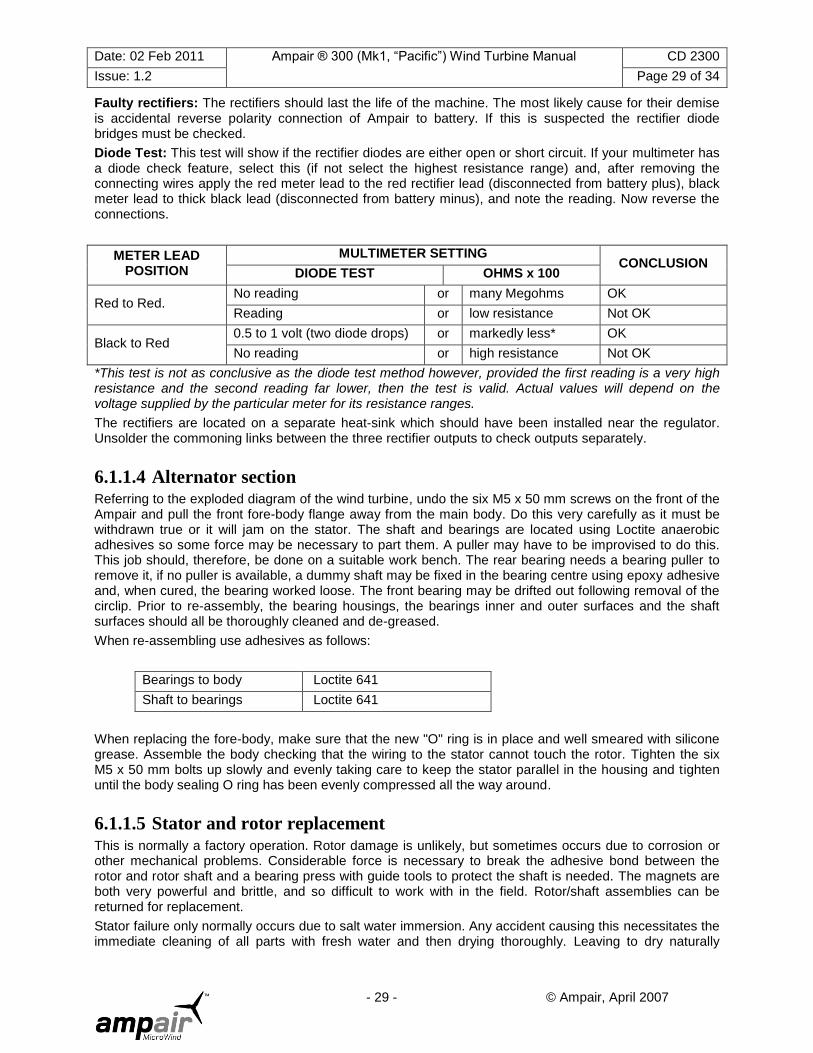
Faulty rectifiers: The rectifiers should last the life of the machine. The most likely cause for their demise is accidental reverse polarity connection of Ampair to battery. If this is suspected the rectifier diode bridges must be checked.
Diode Test: This test will show if the rectifier diodes are either open or short circuit. If your multimeter has a diode check feature, select this (if not select the highest resistance range) and, after removing the connecting wires apply the red meter lead to the red rectifier lead (disconnected from battery plus), black meter lead to thick black lead (disconnected from battery minus), and note the reading. Now reverse the connections.
METER LEAD POSITION
MULTIMETER SETTING CONCLUSION
DIODE TEST OHMS x 100
Red to Red. No reading or many Megohms OK
Reading or low resistance Not OK
Black to Red 0.5 to 1 volt (two diode drops) or markedly less* OK
No reading or high resistance Not OK
*This test is not as conclusive as the diode test method however, provided the first reading is a very high resistance and the second reading far lower, then the test is valid. Actual values will depend on the voltage supplied by the particular meter for its resistance ranges.
The rectifiers are located on a separate heat-sink which should have been installed near the regulator. Unsolder the commoning links between the three rectifier outputs to check outputs separately.
6.1.1.4 Alternator section Referring to the exploded diagram of the wind turbine, undo the six M5 x 50 mm screws on the front of the Ampair and pull the front fore-body flange away from the main body. Do this very carefully as it must be withdrawn true or it will jam on the stator. The shaft and bearings are located using Loctite anaerobic adhesives so some force may be necessary to part them. A puller may have to be improvised to do this. This job should, therefore, be done on a suitable work bench. The rear bearing needs a bearing puller to remove it, if no puller is available, a dummy shaft may be fixed in the bearing centre using epoxy adhesive and, when cured, the bearing worked loose. The front bearing may be drifted out following removal of the circlip. Prior to re-assembly, the bearing housings, the bearings inner and outer surfaces and the shaft surfaces should all be thoroughly cleaned and de-greased.
When re-assembling use adhesives as follows:
Bearings to body Loctite 641
Shaft to bearings Loctite 641
When replacing the fore-body, make sure that the new "O" ring is in place and well smeared with silicone grease. Assemble the body checking that the wiring to the stator cannot touch the rotor. Tighten the six M5 x 50 mm bolts up slowly and evenly taking care to keep the stator parallel in the housing and tighten until the body sealing O ring has been evenly compressed all the way around.
6.1.1.5 Stator and rotor replacement This is normally a factory operation. Rotor damage is unlikely, but sometimes occurs due to corrosion or other mechanical problems. Considerable force is necessary to break the adhesive bond between the rotor and rotor shaft and a bearing press with guide tools to protect the shaft is needed. The magnets are both very powerful and brittle, and so difficult to work with in the field. Rotor/shaft assemblies can be returned for replacement.
Stator failure only normally occurs due to salt water immersion. Any accident causing this necessitates the immediate cleaning of all parts with fresh water and then drying thoroughly. Leaving to dry naturally

Date: 02 Feb 2011 Ampair ® 300 (Mk1, “Pacific”) Wind Turbine Manual CD 2300
Issue: 1.2 Page 30 of 34
- 30 - © Ampair, April 2007
causes the loss of stator winding insulation due to salt corrosion resulting in electrical leakage and shorted turns.

Date: 02 Feb 2011 Ampair ® 300 (Mk1, “Pacific”) Wind Turbine Manual CD 2300
Issue: 1.2 Page 31 of 34
- 31 - © Ampair, April 2007
6.2 Drawings and component list
6.2.1 Exploded drawing

Date: 02 Feb 2011 Ampair ® 300 (Mk1, “Pacific”) Wind Turbine Manual CD 2300
Issue: 1.2 Page 32 of 34
- 32 - © Ampair, April 2007
6.2.2 Key to exploded drawing
Part Number Spares Kit Description
CIRCI47-1 Front bearing retaining circlip
WSHR47-4
AM SP3054
Front bearing washer
BRNG-6204-2RS Front bearing
BRNG-6202-2RSR Rear bearing
ORG1585IX353 Main body O ring
METL00019 Outer bearing spacer
METL00020 Inner bearing spacer
METL00006-1 Alternator shaft
ASMB00013 Slip ring assembly
BRNG-6202-2RSR
AM SP6026
Pivot top bearing
NMETL00002 Pivot lower plain bearing
ORG59IX533 Lower plain bearing O ring
SPRG00002 Spiral retaining ring
SEAL-VA-040 AM SP1030 Pivot shaft V seal
METL00021 Pivot shaft
CBLSR-PG11 Cable gland
ASMB00002 Brush holder assembly
BRSH00001 AM SP3035 Brush set (3 off)
SCRM4x8-06SS M4x8 machine screws
CSTM00005 Electrical box lid
NMETL00006 Insulating washer
SCRM4x12-12SS M4x12 self tapping screws
METL00025 Tail fin
SCRM8x20-01SS M8x20 bolts
NTSM8-01 M8 nuts
CSTM00003 Main body
ASMB00014 Rotor assembly
ASMB00017 Stator assembly
CSTM00002 Front cover
SCRM5x50-01SS M5x50 bolts
ASMB00005 AM SP3012 Hub assembly
NMETL00008 AM SP3014 Blade set (3 off)
METL00014 AM SP3051 Hub cap screw
AM SP3037 Rectifier assembly & heat-sink

Date: 02 Feb 2011 Ampair ® 300 (Mk1, “Pacific”) Wind Turbine Manual CD 2300
Issue: 1.2 Page 33 of 34
- 33 - © Ampair, April 2007
6.3 Recommended spares Depending on location spares worth considering are:
Short term spares:
Spares Kit Comments
Blade set (3 off) AM SP3014 On all sailing boats or at remote locations a spare set of (three) blades should be carried in case of accidental damage.
Pivot seal AM SP1030 In case of loss during servicing
Hub cap screw AM SP3051 In case of loss during assembly
Brush set (3 off) AM SP3035 In case of loss during servicing
Long term spares:
Spares Kit Comments
Pivot seal & bearings AM SP6026 Replacement may be required after several years
Main bearing set AM SP3054 Unlikely to be required but an insurance policy
Rectifier assembly AM SP3037 Unlikely to be required unless polarity is accidentally reversed, however, another insurance policy
Hub AM SP3012 Unlikely to be required but an insurance policy
No special tools are required (except circlip pliers).
7 WARRANTY The Ampair is warranted for two years from the date of purchase.
Any faulty part will be replaced free of charge and any faulty workmanship will be rectified free of charge upon prepaid return of a unit to Ampair or any authorised agents. The unit will then be returned to the customer and freight charged to the customer.
This guarantee does not cover mishandling, accidental damage or faulty installation. Nor can Ampair or its authorised agents be liable for any consequential damage.
Ampair will, nevertheless, go to considerable lengths to ensure customer satisfaction and fully appreciate the problems of those in far away places.
8 SERVICING, REPAIRS, & DISPOSAL Ampair wind turbines may be returned for servicing and repair to:
AMPAIR ENERGY LTD Tel. +44 (0) 1258 837 266
Unit 2 Milborne Business Centre, Fax. +44 (0) 1258 837 496
Blandford Hill, Milborne St Andrew, E-mail [email protected]
Blandford Forum Web site: www.ampair.com
Dorset, DT11 0HZ
UK
At the end of an Ampair 300‟s service life it may be disposed of via normal local recycling facilities. Lead free solders have been used; the main metal components are iron, stainless steel, aluminium, copper, and brass; no unusual coatings have been applied; and the blades do not contain carbon fibre. The Ampair

Date: 02 Feb 2011 Ampair ® 300 (Mk1, “Pacific”) Wind Turbine Manual CD 2300
Issue: 1.2 Page 34 of 34
- 34 - © Ampair, April 2007
300 complies with the WEE and RoHS directives. The packaging materials are only cardboard. Expanded foams have deliberately not been used as a packaging material.