ampconnect isc user manual - listen, inc · ampconnect isctm instruction manual listen software...
TRANSCRIPT
PA©
PA©
AmpConnect ISC™
Microphone & Loudspeaker Test Interface
Instruction Manual
Feb 2017
© Copyright 2009 - 2017 Listen, Inc.
Sound Measurements Make Sound Products
580 Harrison Ave, Suite 3W • Boston, MA 02118 • 617-556-4104 • Fax 617-556-4145 • www.listeninc.com
Listen, Inc. 580 Harrison Ave, Suite 3W, Boston, MA 02118
Listen, Inc. 580 Harrison Ave, Suite 3W, Boston, MA 02118Tel: (617) 556-4104 Fax: (617) 556-4145 Web: www.listeninc.com
Sales: [email protected] Support: [email protected]
AmpConnect ISCUser Manual
TM
N: 8070 REV 092016MPCONNECT ISC USER MANUAL COPYRIGHT 2009-2016 LISTEN, INC.
N: 8070 Rev 052417MPCONNECT ISC USER MANUAL COPYRIGHT 2009-2017 LISTEN, INC.
Tel: (617) 556-4104 Fax: (617) 556-4145 Web: www.listeninc.comSales: [email protected] Support: [email protected], Inc. 580 Harrison Ave, Suite 3W, Boston, MA 02118. Tel: (617) 556-4104.
Web: www.listeninc.com Sales: [email protected] Support: [email protected]

Rev 052417

Contents
Contents. . . . . . . . . . . . . . . . . . . . . . . . . . . . . . . . . . . . . . . . . . . . . . . . . . . . . . . . . . . . . i
Listen Software License Agreement . . . . . . . . . . . . . . . . . . . . . . . . . . . . . . . . . . . . . iii
Limited Warranty. . . . . . . . . . . . . . . . . . . . . . . . . . . . . . . . . . . . . . . . . . . . . . . . . . . . . ix
Introduction . . . . . . . . . . . . . . . . . . . . . . . . . . . . . . . . . . . . . . . . . . . . . . . . . . . . . . . . . 1Control . . . . . . . . . . . . . . . . . . . . . . . . . . . . . . . . . . . . . . . . . . . . . . . . . . . . . . . . . . . . . . . . . . . . . . . . 1Connection . . . . . . . . . . . . . . . . . . . . . . . . . . . . . . . . . . . . . . . . . . . . . . . . . . . . . . . . . . . . . . . . . . . . 1Key Features . . . . . . . . . . . . . . . . . . . . . . . . . . . . . . . . . . . . . . . . . . . . . . . . . . . . . . . . . . . . . . . . . . . 2Test Setup Comparison . . . . . . . . . . . . . . . . . . . . . . . . . . . . . . . . . . . . . . . . . . . . . . . . . . . . . . . . . . 3
Installation . . . . . . . . . . . . . . . . . . . . . . . . . . . . . . . . . . . . . . . . . . . . . . . . . . . . . . . . . . 5Requirements . . . . . . . . . . . . . . . . . . . . . . . . . . . . . . . . . . . . . . . . . . . . . . . . . . . . . . . . . . . . . . . . . . 5Software Installation. . . . . . . . . . . . . . . . . . . . . . . . . . . . . . . . . . . . . . . . . . . . . . . . . . . . . . . . . . . . . 5Audio Device Settings . . . . . . . . . . . . . . . . . . . . . . . . . . . . . . . . . . . . . . . . . . . . . . . . . . . . . . . . . . . 6System Settings . . . . . . . . . . . . . . . . . . . . . . . . . . . . . . . . . . . . . . . . . . . . . . . . . . . . . . . . . . . . . . . . 7Physical Installation . . . . . . . . . . . . . . . . . . . . . . . . . . . . . . . . . . . . . . . . . . . . . . . . . . . . . . . . . . . . . 8
Hardware and Calibration. . . . . . . . . . . . . . . . . . . . . . . . . . . . . . . . . . . . . . . . . . . . . . 9SoundCheck System Hardware. . . . . . . . . . . . . . . . . . . . . . . . . . . . . . . . . . . . . . . . . . . . . . . . . . . . 9Self Test Sequence . . . . . . . . . . . . . . . . . . . . . . . . . . . . . . . . . . . . . . . . . . . . . . . . . . . . . . . . . . . . . 12Amplifier Calibration. . . . . . . . . . . . . . . . . . . . . . . . . . . . . . . . . . . . . . . . . . . . . . . . . . . . . . . . . . . . 13
Front Panel Functions . . . . . . . . . . . . . . . . . . . . . . . . . . . . . . . . . . . . . . . . . . . . . . . 17Headphone Output . . . . . . . . . . . . . . . . . . . . . . . . . . . . . . . . . . . . . . . . . . . . . . . . . . . . . . . . . . . . . 17Control . . . . . . . . . . . . . . . . . . . . . . . . . . . . . . . . . . . . . . . . . . . . . . . . . . . . . . . . . . . . . . . . . . . . . . . 17Input - Physical Inputs on Rear Panel. . . . . . . . . . . . . . . . . . . . . . . . . . . . . . . . . . . . . . . . . . . . . . 19Output - Physical Input Routing to Internal Audio Interface . . . . . . . . . . . . . . . . . . . . . . . . . . . 20Amplifier . . . . . . . . . . . . . . . . . . . . . . . . . . . . . . . . . . . . . . . . . . . . . . . . . . . . . . . . . . . . . . . . . . . . . 21
Rear Panel Connections. . . . . . . . . . . . . . . . . . . . . . . . . . . . . . . . . . . . . . . . . . . . . . 23Reference (Microphone) Input . . . . . . . . . . . . . . . . . . . . . . . . . . . . . . . . . . . . . . . . . . . . . . . . . . . . 23DUT (Microphone) Input . . . . . . . . . . . . . . . . . . . . . . . . . . . . . . . . . . . . . . . . . . . . . . . . . . . . . . . . . 24Amplifier . . . . . . . . . . . . . . . . . . . . . . . . . . . . . . . . . . . . . . . . . . . . . . . . . . . . . . . . . . . . . . . . . . . . . 24Digital I/O . . . . . . . . . . . . . . . . . . . . . . . . . . . . . . . . . . . . . . . . . . . . . . . . . . . . . . . . . . . . . . . . . . . . . 24USB . . . . . . . . . . . . . . . . . . . . . . . . . . . . . . . . . . . . . . . . . . . . . . . . . . . . . . . . . . . . . . . . . . . . . . . . . 24
Contents
AmpConnect ISCTM Instruction Manual Contents i

USB Control Via SoundCheck . . . . . . . . . . . . . . . . . . . . . . . . . . . . . . . . . . . . . . . . . 25Create Message Step . . . . . . . . . . . . . . . . . . . . . . . . . . . . . . . . . . . . . . . . . . . . . . . . . . . . . . . . . . . 25AmpConnect Message Step . . . . . . . . . . . . . . . . . . . . . . . . . . . . . . . . . . . . . . . . . . . . . . . . . . . . . . 26Configure AmpConnect in SoundCheck 14 and Later. . . . . . . . . . . . . . . . . . . . . . . . . . . . . . . . . 27Configure AmpConnect in SoundCheck 13 and Previous Versions . . . . . . . . . . . . . . . . . . . . . 29Custom Step Conversion . . . . . . . . . . . . . . . . . . . . . . . . . . . . . . . . . . . . . . . . . . . . . . . . . . . . . . . . 30
Digital I/O Connections . . . . . . . . . . . . . . . . . . . . . . . . . . . . . . . . . . . . . . . . . . . . . . . 33Reading External Switch Closures . . . . . . . . . . . . . . . . . . . . . . . . . . . . . . . . . . . . . . . . . . . . . . . . 33AmpConnect ISC Message Step . . . . . . . . . . . . . . . . . . . . . . . . . . . . . . . . . . . . . . . . . . . . . . . . . . 37
Test Connections and Procedures . . . . . . . . . . . . . . . . . . . . . . . . . . . . . . . . . . . . . 39Single Loudspeaker Test . . . . . . . . . . . . . . . . . . . . . . . . . . . . . . . . . . . . . . . . . . . . . . . . . . . . . . . . 39Two Loudspeaker Test . . . . . . . . . . . . . . . . . . . . . . . . . . . . . . . . . . . . . . . . . . . . . . . . . . . . . . . . . . 40Microphone Test . . . . . . . . . . . . . . . . . . . . . . . . . . . . . . . . . . . . . . . . . . . . . . . . . . . . . . . . . . . . . . . 41User Setup Notes . . . . . . . . . . . . . . . . . . . . . . . . . . . . . . . . . . . . . . . . . . . . . . . . . . . . . . . . . . . . . . 42
Headphone Testing . . . . . . . . . . . . . . . . . . . . . . . . . . . . . . . . . . . . . . . . . . . . . . . . . . 43Required Changes. . . . . . . . . . . . . . . . . . . . . . . . . . . . . . . . . . . . . . . . . . . . . . . . . . . . . . . . . . . . . . 43Setup & Calibration . . . . . . . . . . . . . . . . . . . . . . . . . . . . . . . . . . . . . . . . . . . . . . . . . . . . . . . . . . . . . 44AmpConnect Front Panel Settings . . . . . . . . . . . . . . . . . . . . . . . . . . . . . . . . . . . . . . . . . . . . . . . . 45AmpConnect Message Step . . . . . . . . . . . . . . . . . . . . . . . . . . . . . . . . . . . . . . . . . . . . . . . . . . . . . . 46Sequence Results . . . . . . . . . . . . . . . . . . . . . . . . . . . . . . . . . . . . . . . . . . . . . . . . . . . . . . . . . . . . . . 47
AmpConnect ISC Block Diagram . . . . . . . . . . . . . . . . . . . . . . . . . . . . . . . . . . . . . . . 49Block Diagram Explanations . . . . . . . . . . . . . . . . . . . . . . . . . . . . . . . . . . . . . . . . . . . . . . . . . . . . . 50
Internal Jumper Settings. . . . . . . . . . . . . . . . . . . . . . . . . . . . . . . . . . . . . . . . . . . . . . 51
AmpConnect ISC Specifications . . . . . . . . . . . . . . . . . . . . . . . . . . . . . . . . . . . . . . . 53
INDEX . . . . . . . . . . . . . . . . . . . . . . . . . . . . . . . . . . . . . . . . . . . . . . . . . . . . . . . . . . . . . 55
ii Contents AmpConnect ISCTM Instruction Manual

Listen Software License Agreement
READ THE TERMS AND CONDITIONS OF THIS LICENSE AGREEMENT CAREFULLY BEFORE INSTALLING THIS SOFTWARE. THE SOFTWARE IS COPYRIGHTED AND LICENSED (NOT SOLD). BY INSTALLING THIS SOFTWARE, YOU ARE ACCEPTING AND AGREEING TO THE TERMS OF THIS LICENSE AGREEMENT. IF YOU ARE NOT WILLING TO BE BOUND BY THE TERMS OF THIS LICENSE AGREEMENT, YOU SHOULD RETURN THE SOFTWARE, HARDWARE KEY, AND DOCUMENTATION WITHIN THIRTY (30) DAYS OF YOUR INVOICE DATE, AND YOU WILL RECEIVE A CREDIT OR A REFUND.
The enclosed Software is provided to the purchaser of the Software ("End-User") by LISTEN, Inc., ("Licen-sor") for use only under the terms set forth in this Agreement. Licensor reserves any right not expressly granted to the End-User. The End-User owns the disk on which the Software is recorded, but Licensor retains ownership of all copies of the Software itself. The End-User assumes sole responsibility for the installation, use and results obtained from use of the Software.
1. License. Licensor grants to End-User a limited, non-exclusive and nontransferable license to install, maintain and use the Software in object code form on a single computer owned or leased by End-User solely in connection with the End-User's own business. End-User may make one copy of the Software, in machine-readable form, solely for backup or archival purposes for the computer on which the Software is installed. The Software is protected by copyright law. As an express condition of this License, the End-User must reproduce on the copy Licensor's copyright notice and any other proprietary legends on the original copy supplied by Licensor.
2. Restrictions. End-User agrees that the Software is a proprietary product and that all right, title and inter-est in and to the Software, including all associated intellectual property rights, are and shall at all times remain with Licensor. End-User may NOT sublicense, assign, or distribute copies of the Software to others. THE END-USER MAY NOT DECOMPILE, REVERSE ENGINEER, DISASSEMBLE, OR OTHERWISE REDUCE THE SOFTWARE TO A HUMAN READABLE FORM. THE END-USER MAY NOT MODIFY, ADAPT, TRANSLATE, RENT, LEASE, LOAN, RESELL FOR PROFIT, DISTRIBUTE, OR OTHERWISE ASSIGN OR TRANSFER THE SOFTWARE, OR CREATE DERIVATIVE WORKS BASED UPON THE SOFTWARE OR ANY PART THEREOF.
3. Protection and Security. End-User agrees that the Software contains trade secrets, proprietary informa-tion and copyrighted material of Licensor. End-User agrees to use its best efforts and to take all reasonable steps to safeguard the Software to ensure that no unauthorized person shall have access thereto and that no unauthorized copy, publication, disclosure or distribution, in whole or in part, in any form, shall be made. End-User acknowledges that the Software contains valuable confidential information and that unauthorized use and/or copying are harmful to Licensor. End-User agrees to assist and cooperate with Licensor in the identification and removal of illegal copies of Listen software or software based on Listen’s source-code located on the End-User’s computer, computer system, or at End-User’s place of business. End-User agrees to only install and use authorized, genuine and licensed versions of the Software. Installation or use of any unlicensed or illegal copies, or software based on Listen’s source code shall be deemed a material breach of this Agreement.
4. Termination. This License is effective until terminated. This License will terminate immediately without notice from Licensor if the End-User fails to comply with any of its provisions. Upon termination the End-User must destroy the Software and all copies thereof. End-User may terminate this License at any time by destroying the Software and all copies thereof.
AmpConnect ISCTM Instruction Manual Listen Software License Agreement iii

5. Limited Warranty. Licensor warrants that, for ninety (90) days from the date of shipment by Licensor (i) the media on which the software is furnished will be free of defects in materials and workmanship under normal use; and (ii) the Software conforms to its published functional specifications current at the time of shipment. Except for the foregoing, the Software is provided AS IS. If, during the warranty period, a defect appears, End-User shall return the Software to Licensor and Licensor's only obligation shall be, at Licen-sor's election, to replace the defective Software or refund the purchase price. The End-User agrees that the foregoing constitutes the End-User's sole and exclusive remedy for breach by Licensor under any warran-ties made under this Agreement. This warranty does not apply if the Software (i) has been altered or changed in any way by anyone other than Licensor; (ii) has not been installed, operated, repaired or main-tained in accordance with instructions supplied by Licensor (including the use of other Software versions) or (iii) has been subjected to abnormal physical or electrical stress, misuse, negligence or accident. Licensor is not responsible for problems associated with or caused by incompatible operating systems or equipment, or for problems in the interaction of the Software with software not furnished by Licensor.
No oral or written information or advice given by Licensor or its dealers, distributors, employees or agents shall in any way extend, modify or add to the foregoing warranty.
THE WARRANTY AND REMEDY PROVIDED ABOVE ARE EXCLUSIVE AND IN LIEU OF ALL OTHER WARRANTIES, EXPRESS OR IMPLIED, INCLUDING BUT NOT LIMITED TO THE IMPLIED WARRAN-TIES OF MERCHANTABILITY AND FITNESS FOR A PARTICULAR PURPOSE. THE END-USER ASSUMES ALL RISK AS TO THE SUITABILITY, QUALITY, AND PERFORMANCE OF THE SOFTWARE.
6. LIMITATION OF LIABILITY. IN NO EVENT WILL LICENSOR, OR ITS DIRECTORS, OFFICERS, EMPLOYEES, CONSULTANTS, INDEPENDENT CONTRACTORS, AGENTS OR AFFILIATES, BE LIA-BLE TO THE END-USER FOR ANY CONSEQUENTIAL, INCIDENTAL, INDIRECT, SPECIAL OR EXEM-PLARY DAMAGES (INCLUDING DAMAGES FOR LOSS OF BUSINESS REVENUES OR PROFITS, BUSINESS INTERRUPTION, LOSS OF DATA OR BUSINESS INFORMATION, AND THE LIKE), HOW-EVER CAUSED AND REGARDLESS OF THE THEORY OF LIABILITY, INCLUDING NEGLIGENCE, ARISING OUT OF THE USE OF OR INABILITY TO USE THE SOFTWARE OR ACCOMPANYING WRIT-TEN MATERIALS, EVEN IF LICENSOR HAS BEEN ADVISED OF THE POSSIBILITY OF SUCH DAM-AGES.
LICENSOR'S LIABILITY TO THE END-USER (IF ANY) FOR ACTUAL DIRECT DAMAGES, HOWEVER CAUSED AND REGARDLESS OF THE THEORY OF LIABILITY, INCLUDING NEGLIGENCE, WILL BE LIMITED TO, AND IN NO EVENT SHALL EXCEED, THE AMOUNT ORIGINALLY PAID TO LICENSOR FOR THE LICENSE OF THE SOFTWARE.
7. Enhancements. From time to time Licensor may, in its sole discretion, advise the End-User of updates, upgrades, enhancements or improvements to the Software and/or new releases of the Software (collec-tively, "Enhancements"), and may license the End-User to use such Enhancements upon payment of prices as may be established by Licensor from time to time. All such Enhancements to the Software provided to the End-User shall also be governed by the terms of this License. IN ORDER FOR THE END-USER TO BE ASSURED THAT IT WILL BE ADVISED OF AND LICENSED TO USE ANY ENHANCEMENTS TO THE SOFTWARE, THE END-USER MUST REGISTER THEIR SOFTWARE AT www.listeninc.com/register.
8. Export Regulations. Software, including technical data, is subject to U.S. export control laws, including the U.S. Export Administration Act and its associated regulations, and may be subject to export or import regulations of other countries. End-User agrees to strictly comply with all such regulations and acknowl-edges that it has the responsibility to obtain licenses to export, re-export or import Software.
AmpConnect ISCTM Instruction Manual Listen Software License Agreement iv

9. General. This License will be governed by and construed in accordance with the laws of the Common-wealth of Massachusetts and the United States, and shall inure to the benefit of Licensor and End-User and their successors, assigns and legal representatives. Any action, suit or proceeding arising out of under or in connection with this Agreement whether, brought for equitable relief or money damages shall be brought exclusively in either state or federal court in Suffolk County, Massachusetts. Licensee irrevocably and unconditionally submits to the exclusive jurisdiction and venue of such courts and agrees to take any and all future action necessary to submit to the jurisdiction of such courts. Final judgment in any such suit shall be conclusive and may be enforced in other jurisdictions by suit on the judgment, a certified or true copy of which shall be conclusive evidence of the fact and the amount of any liability therein described, or by appro-priate proceedings under any applicable treaty or otherwise. If any provision of this License is held by a court of competent jurisdiction to be invalid or unenforceable to any extent under applicable law, that provi-sion will be enforced to the maximum extent permissible and the remaining provisions of this License will remain in full force and effect. Any notices or other communications to be sent to Licensor must be mailed first class, postage prepaid, to the following address:
LISTEN, Inc.
580 Harrison Ave.,
Suite 3W,
Boston, MA 02118
This Agreement constitutes the entire agreement between the parties with respect to the subject matter hereof, and all prior proposals, agreements, representations, statements and undertakings are hereby expressly cancelled and superseded. This Agreement may not be changed or amended except by a written instrument executed by a duly authorized officer of Licensor.
10. Acknowledgment. BY OPENING THIS PACKAGE AND/OR INSTALLING THIS SOFTWARE, THE END-USER ACKNOWLEDGES THAT IT HAS READ THIS LICENSE, UNDERSTANDS IT, AND AGREES TO BE BOUND BY ITS TERMS AND CONDITIONS. Should you have any questions concerning this License, contact Licensor at the address set forth above.
AmpConnect ISCTM Instruction Manual Listen Software License Agreement v

LISTEN
(30)
LISTEN, Inc.( )
1.
2.
3.
/
4.
5. 90 iii
iii
iii
AmpConnect ISCTM Instruction Manual Listen Software License Agreement vi
6.
7. //“ ”
www.listeninc.com/register <http://www.listeninc.com/register>
8.
9.
LISTEN, Inc.
580 Harrison Ave.,
Suite 2A,
Boston, MA 02118
LISTEN, Inc.
580 Harrison Ave.,
Suite 3W,
Boston, MA 02118
AmpConnect ISCTM Instruction Manual Listen Software License Agreement vii

10. /
AmpConnect ISCTM Instruction Manual Listen Software License Agreement viii
Limited Warranty
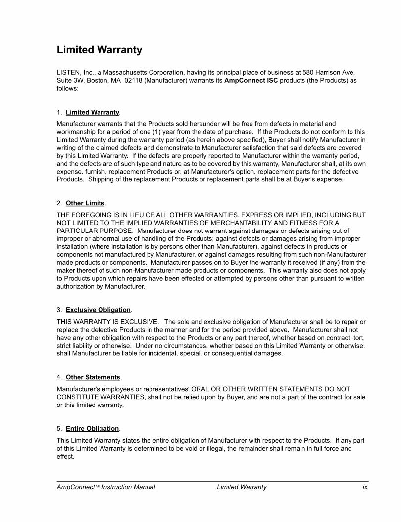
LISTEN, Inc., a Massachusetts Corporation, having its principal place of business at 580 Harrison Ave, Suite 3W, Boston, MA 02118 (Manufacturer) warrants its AmpConnect ISC products (the Products) as follows:
1. Limited Warranty.
Manufacturer warrants that the Products sold hereunder will be free from defects in material and workmanship for a period of one (1) year from the date of purchase. If the Products do not conform to this Limited Warranty during the warranty period (as herein above specified), Buyer shall notify Manufacturer in writing of the claimed defects and demonstrate to Manufacturer satisfaction that said defects are covered by this Limited Warranty. If the defects are properly reported to Manufacturer within the warranty period, and the defects are of such type and nature as to be covered by this warranty, Manufacturer shall, at its own expense, furnish, replacement Products or, at Manufacturer's option, replacement parts for the defective Products. Shipping of the replacement Products or replacement parts shall be at Buyer's expense.
2. Other Limits.
THE FOREGOING IS IN LIEU OF ALL OTHER WARRANTIES, EXPRESS OR IMPLIED, INCLUDING BUT NOT LIMITED TO THE IMPLIED WARRANTIES OF MERCHANTABILITY AND FITNESS FOR A PARTICULAR PURPOSE. Manufacturer does not warrant against damages or defects arising out of improper or abnormal use of handling of the Products; against defects or damages arising from improper installation (where installation is by persons other than Manufacturer), against defects in products or components not manufactured by Manufacturer, or against damages resulting from such non-Manufacturer made products or components. Manufacturer passes on to Buyer the warranty it received (if any) from the maker thereof of such non-Manufacturer made products or components. This warranty also does not apply to Products upon which repairs have been effected or attempted by persons other than pursuant to written authorization by Manufacturer.
3. Exclusive Obligation.
THIS WARRANTY IS EXCLUSIVE. The sole and exclusive obligation of Manufacturer shall be to repair or replace the defective Products in the manner and for the period provided above. Manufacturer shall not have any other obligation with respect to the Products or any part thereof, whether based on contract, tort, strict liability or otherwise. Under no circumstances, whether based on this Limited Warranty or otherwise, shall Manufacturer be liable for incidental, special, or consequential damages.
4. Other Statements.
Manufacturer's employees or representatives' ORAL OR OTHER WRITTEN STATEMENTS DO NOT CONSTITUTE WARRANTIES, shall not be relied upon by Buyer, and are not a part of the contract for sale or this limited warranty.
5. Entire Obligation.
This Limited Warranty states the entire obligation of Manufacturer with respect to the Products. If any part of this Limited Warranty is determined to be void or illegal, the remainder shall remain in full force and effect.
AmpConnectTM Instruction Manual Limited Warranty ix

page intentionally left blank
x Limited Warranty AmpConnectTM Instruction Manual
Introduction
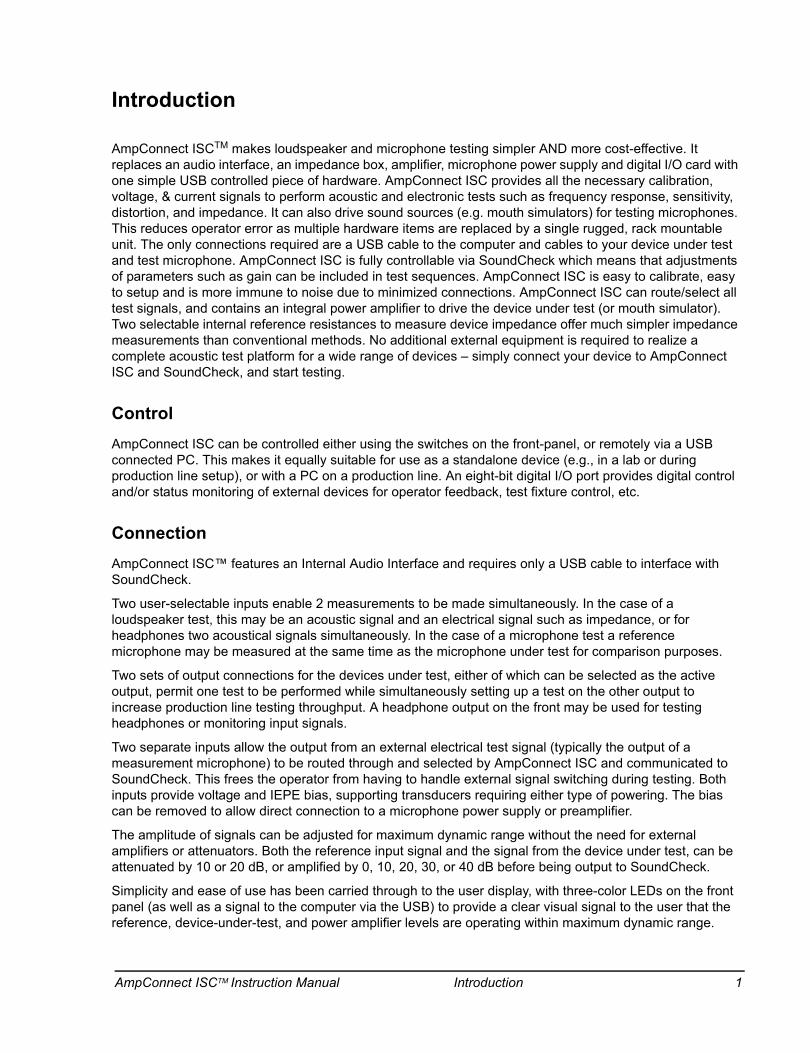
AmpConnect ISCTM makes loudspeaker and microphone testing simpler AND more cost-effective. It replaces an audio interface, an impedance box, amplifier, microphone power supply and digital I/O card with one simple USB controlled piece of hardware. AmpConnect ISC provides all the necessary calibration, voltage, & current signals to perform acoustic and electronic tests such as frequency response, sensitivity, distortion, and impedance. It can also drive sound sources (e.g. mouth simulators) for testing microphones. This reduces operator error as multiple hardware items are replaced by a single rugged, rack mountable unit. The only connections required are a USB cable to the computer and cables to your device under test and test microphone. AmpConnect ISC is fully controllable via SoundCheck which means that adjustments of parameters such as gain can be included in test sequences. AmpConnect ISC is easy to calibrate, easy to setup and is more immune to noise due to minimized connections. AmpConnect ISC can route/select all test signals, and contains an integral power amplifier to drive the device under test (or mouth simulator). Two selectable internal reference resistances to measure device impedance offer much simpler impedance measurements than conventional methods. No additional external equipment is required to realize a complete acoustic test platform for a wide range of devices – simply connect your device to AmpConnect ISC and SoundCheck, and start testing.
ControlAmpConnect ISC can be controlled either using the switches on the front-panel, or remotely via a USB connected PC. This makes it equally suitable for use as a standalone device (e.g., in a lab or during production line setup), or with a PC on a production line. An eight-bit digital I/O port provides digital control and/or status monitoring of external devices for operator feedback, test fixture control, etc.
ConnectionAmpConnect ISC™ features an Internal Audio Interface and requires only a USB cable to interface with SoundCheck.
Two user-selectable inputs enable 2 measurements to be made simultaneously. In the case of a loudspeaker test, this may be an acoustic signal and an electrical signal such as impedance, or for headphones two acoustical signals simultaneously. In the case of a microphone test a reference microphone may be measured at the same time as the microphone under test for comparison purposes.
Two sets of output connections for the devices under test, either of which can be selected as the active output, permit one test to be performed while simultaneously setting up a test on the other output to increase production line testing throughput. A headphone output on the front may be used for testing headphones or monitoring input signals.
Two separate inputs allow the output from an external electrical test signal (typically the output of a measurement microphone) to be routed through and selected by AmpConnect ISC and communicated to SoundCheck. This frees the operator from having to handle external signal switching during testing. Both inputs provide voltage and IEPE bias, supporting transducers requiring either type of powering. The bias can be removed to allow direct connection to a microphone power supply or preamplifier.
The amplitude of signals can be adjusted for maximum dynamic range without the need for external amplifiers or attenuators. Both the reference input signal and the signal from the device under test, can be attenuated by 10 or 20 dB, or amplified by 0, 10, 20, 30, or 40 dB before being output to SoundCheck.
Simplicity and ease of use has been carried through to the user display, with three-color LEDs on the front panel (as well as a signal to the computer via the USB) to provide a clear visual signal to the user that the reference, device-under-test, and power amplifier levels are operating within maximum dynamic range.
AmpConnect ISCTM Instruction Manual Introduction 1
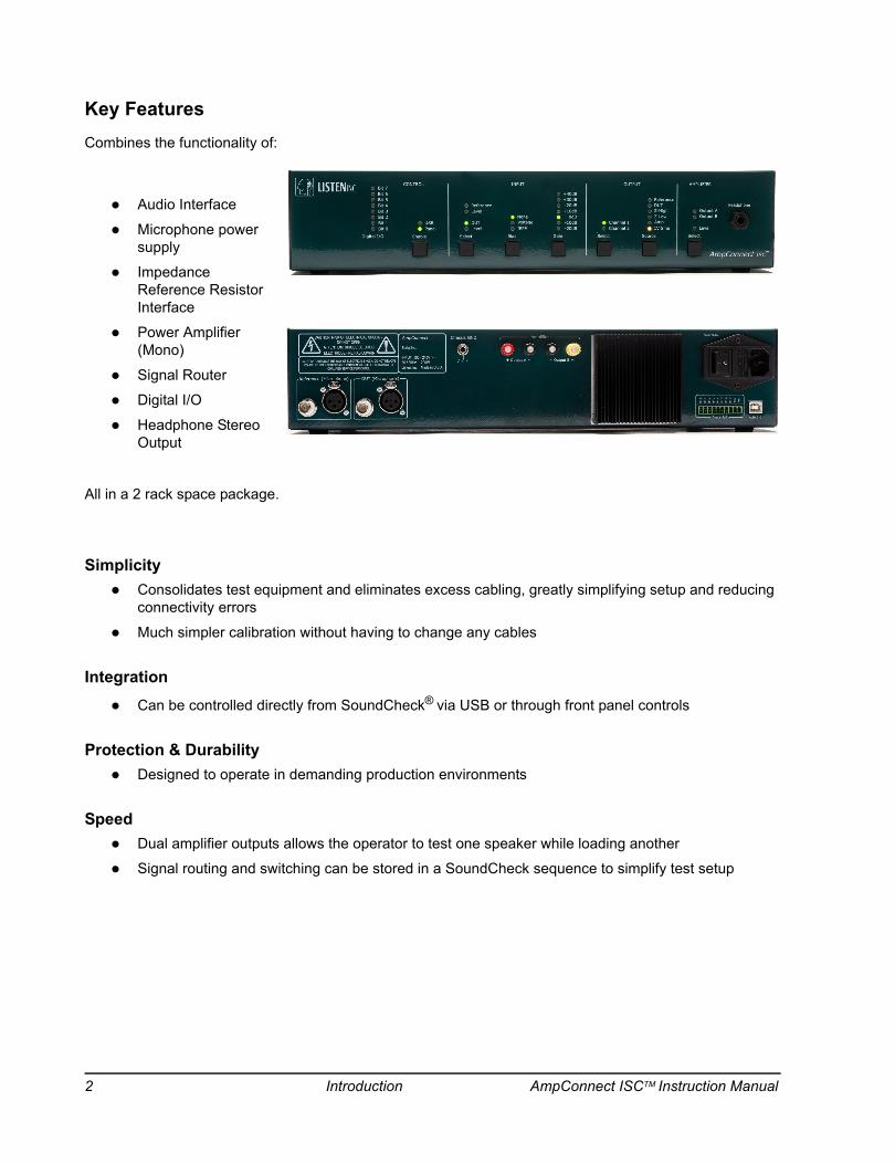
Key FeaturesCombines the functionality of:
Audio Interface
Microphone power supply
Impedance Reference Resistor Interface
Power Amplifier (Mono)
Signal Router
Digital I/O
Headphone Stereo Output
All in a 2 rack space package.
SimplicityConsolidates test equipment and eliminates excess cabling, greatly simplifying setup and reducing connectivity errors
Much simpler calibration without having to change any cables
IntegrationCan be controlled directly from SoundCheck® via USB or through front panel controls
Protection & DurabilityDesigned to operate in demanding production environments
SpeedDual amplifier outputs allows the operator to test one speaker while loading another
Signal routing and switching can be stored in a SoundCheck sequence to simplify test setup
2 Introduction AmpConnect ISCTM Instruction Manual
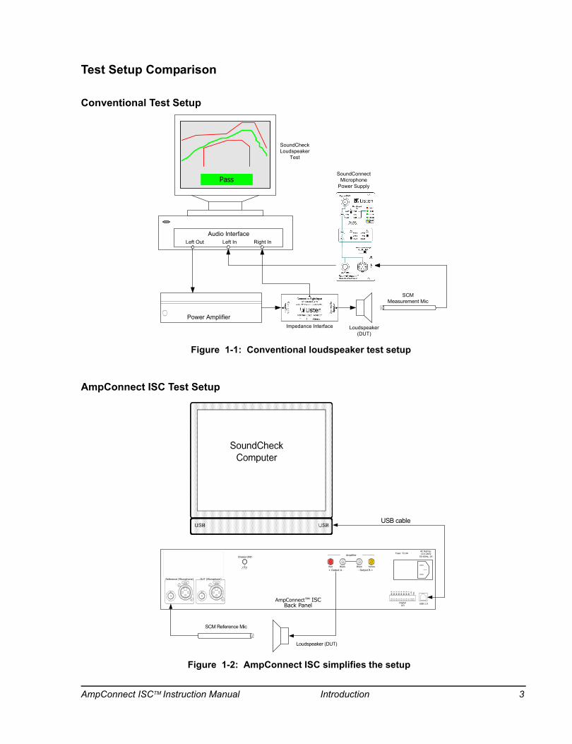
Test Setup Comparison
Conventional Test Setup
AmpConnect ISC Test Setup
SCMMeasurement Mic
Loudspeaker (DUT)
Power Amplifier
Audio Interface
Pass
Left Out Left In Right In
Impedance Interface
SoundConnectMicrophone
Power Supply
SoundCheckLoudspeaker
Test
Figure 1-1: Conventional loudspeaker test setup
PUSH
CAUTIONRISK OF ELECTRICAL
SHOCKDO NOT OPEN
CAUTION: TO REDUCE THE RISK OF ELECTRICAL SHOCK, DO NOT REMOVE COVER. NO USER-SERVICABLE PARTS INSIDE. REFER
SERVICING TO QUALIFIED SERVICE PERSONNEL.
Reference (Microphone) DUT (Microphone)
USB 2.0DigitalI/O
AC Rating:110-240V
50-60Hz, 2AFuse: T2.0A
Bit
0B
it 1
Bit
2B
it 3
Bit
4B
it 5
Bit
6B
it 7
+5V
Ret
.
PUSH
Chassis GND
SCM Reference Mic
Loudspeaker (DUT)
USB cable
- Output B ++ Output A -
Amplifier
Red Black Black Yellow
AmpConnect™ ISCBack Panel
Figure 1-2: AmpConnect ISC simplifies the setup
AmpConnect ISCTM Instruction Manual Introduction 3
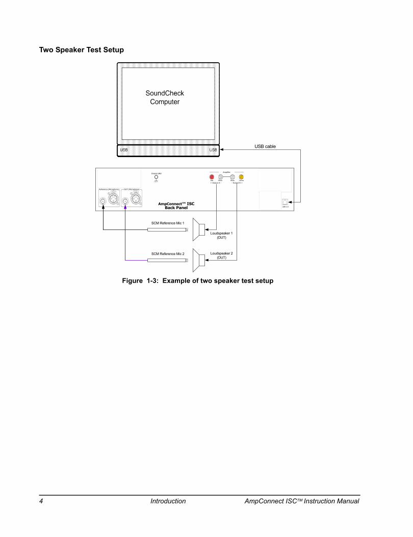
Two Speaker Test Setup
PUSH
CAUTIONRISK OF ELECTRICAL
SHOCKDO NOT OPEN
CAUTION: TO REDUCE THE RISK OF ELECTRICAL SHOCK, DO NOT REMOVE COVER. NO USER-SERVICABLE PARTS INSIDE. REFER
SERVICING TO QUALIFIED SERVICE PERSONNEL.
Reference (Microphone) DUT (Microphone)
USB 2.0DigitalI/O
AC Rating:110-240V
50-60Hz, 2AFuse: T2.0A
Bit
0Bit
1Bit
2Bit
3Bit
4Bit
5Bit
6Bit
7+
5VR
et.
PUSH
Chassis GND
SCM Reference Mic 1
Loudspeaker 1(DUT)
USB cable
- Output B ++ Output A -
Amplifier
Red Black Black Yellow
Loudspeaker 2(DUT)
AmpConnect™ ISCBack Panel
SCM Reference Mic 2
Figure 1-3: Example of two speaker test setup
4 Introduction AmpConnect ISCTM Instruction Manual

Installation
RequirementsSoundCheck 10.11 minimum (or SoundCheck ONE) is required in order to control AmpConnect ISC™ via USB
The SoundCheck computer must have an available USB 2.0 connection
Note: It is recommended that AmpConnect ISC be mounted in a ventilated rack mount enclosure for proper cooling.
Software Installation
Important! Rockey Hardware Key only: Make sure the SoundCheck USB hardware key is not connected to the computer. If it is connected while installing AmpConnect ISC or SoundCheck, the hardware key could be destroyed. Do not unplug the hardware key while SoundCheck is running. Doing so could destroy the hardware key.
Install SoundCheck first!Before connecting AmpConnect ISC to a USB port of your SoundCheck System, SoundCheck must be installed. The AmpConnect ISC driver installation is part of the SoundCheck software install process.
Important! As of SoundCheck 13, a new driver for AmpConnect ISC has been included in the SoundCheck installation process. The new driver will not work in versions prior to SoundCheck 13. To use AmpConnect ISC with SoundCheck 12 (and previously supported versions), you will need to manually rollback the device driver in Windows Device Manager. See AmpConnect Driver Rollback Procedure on page 1.
Important! After installing SC 14, prior versions of SoundCheck will not have control over the device. Additionally, the serial number of the AmpConnect audio interface will not be read properly which changes the name of the device in the Hardware Editor.
AmpConnect ISCTM Instruction Manual Installation 5
Prior to SoundCheck 13AmpConnect ISC requires Microsoft .NET Framework 2.0 sp1 (or later). SoundCheck 11 and 12 include .NET Framework 2.0.
The SoundCheck 11 installation process will check to see if .NET Framework is installed. If not, you are prompted to install the required application.
Note: An internet connect is required in order to download the Microsoft application. If the SoundCheck system does not have internet access, the NET framework installer can be download on a different PC and then copied to the system manually.
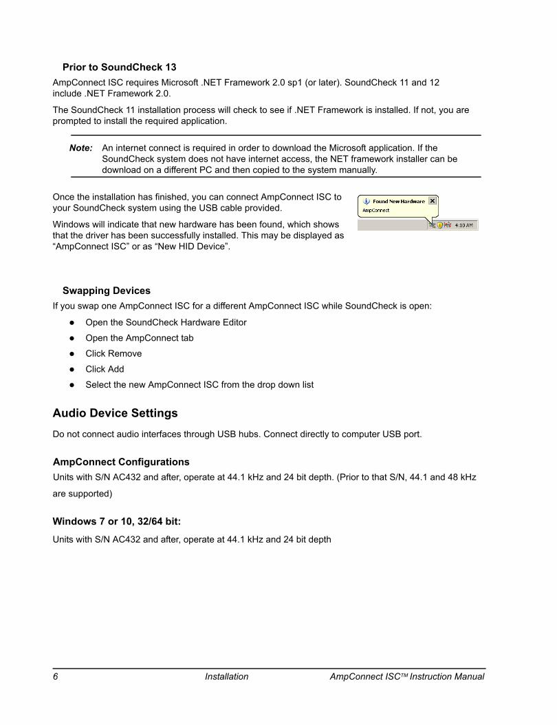
Once the installation has finished, you can connect AmpConnect ISC to your SoundCheck system using the USB cable provided.
Windows will indicate that new hardware has been found, which shows that the driver has been successfully installed. This may be displayed as “AmpConnect ISC” or as “New HID Device”.
Swapping DevicesIf you swap one AmpConnect ISC for a different AmpConnect ISC while SoundCheck is open:
Open the SoundCheck Hardware Editor
Open the AmpConnect tab
Click Remove
Click Add
Select the new AmpConnect ISC from the drop down list
Audio Device SettingsDo not connect audio interfaces through USB hubs. Connect directly to computer USB port.
AmpConnect ConfigurationsUnits with S/N AC432 and after, operate at 44.1 kHz and 24 bit depth. (Prior to that S/N, 44.1 and 48 kHz
are supported)
Windows 7 or 10, 32/64 bit:
Units with S/N AC432 and after, operate at 44.1 kHz and 24 bit depth
6 Installation AmpConnect ISCTM Instruction Manual
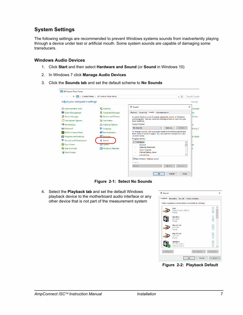
System SettingsThe following settings are recommended to prevent Windows systems sounds from inadvertently playing through a device under test or artificial mouth. Some system sounds are capable of damaging some transducers.
Windows Audio Devices1. Click Start and then select Hardware and Sound (or Sound in Windows 10)
2. In Windows 7 click Manage Audio Devices
3. Click the Sounds tab and set the default scheme to No Sounds
4. Select the Playback tab and set the default Windows playback device to the motherboard audio interface or any other device that is not part of the measurement system
Figure 2-1: Select No Sounds
Figure 2-2: Playback Default
AmpConnect ISCTM Instruction Manual Installation 7

5. Select the Recording tab and set the default recording device to the motherboard sound card or any other device that is not part of the measurement system
6. Click OK and close the remaining Control Panel windows
Physical Installation
Airflow around the heat sink must remain unobstructed during use
DO NOT install AmpConnect inside an enclosure without a ventilation fan
When installed in a rack, AmpConnects should not be installed on top of each other. Leave airspace for cooling.
Figure 2-3: Recording Default
8 Installation AmpConnect ISCTM Instruction Manual
Hardware and Calibration
AmpConnect ISC acts as a complete audio interface for test and measurement with SoundCheck software.
The Hardware Configuration in SoundCheck must be setup for use with AmpConnect.
SoundCheck System Hardware
Important! This section is for use with the full version of SoundCheck. The System Hardware Configuration in SoundCheck ONE is preset for use with AmpConnect ISC. The features noted are only available in the full version of SoundCheck.
Important! As of SoundCheck 11, Hardware and Calibration are “System Level” configurations. They are unique to a specific SoundCheck system and are used by all sequences. Individual steps are no longer used. Settings from these steps can be imported in the Hardware and Calibration Configuration Editors. Refer to the main SoundCheck manual for more information.
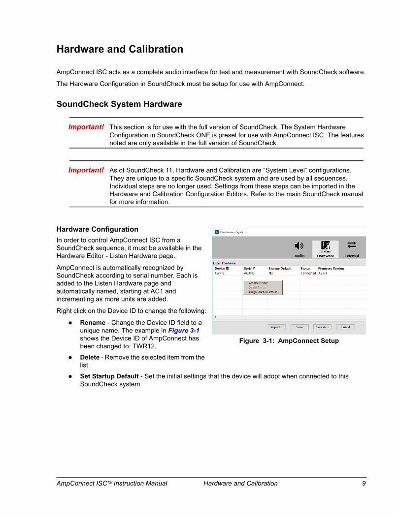
Hardware ConfigurationIn order to control AmpConnect ISC from a SoundCheck sequence, it must be available in the Hardware Editor - Listen Hardware page.
AmpConnect is automatically recognized by SoundCheck according to serial number. Each is added to the Listen Hardware page and automatically named, starting at AC1 and incrementing as more units are added.
Right click on the Device ID to change the following:
Rename - Change the Device ID field to a unique name. The example in Figure 3-1 shows the Device ID of AmpConnect has been changed to: TWR12.
Delete - Remove the selected item from the list
Set Startup Default - Set the initial settings that the device will adopt when connected to this SoundCheck system
Figure 3-1: AmpConnect Setup
AmpConnect ISCTM Instruction Manual Hardware and Calibration 9
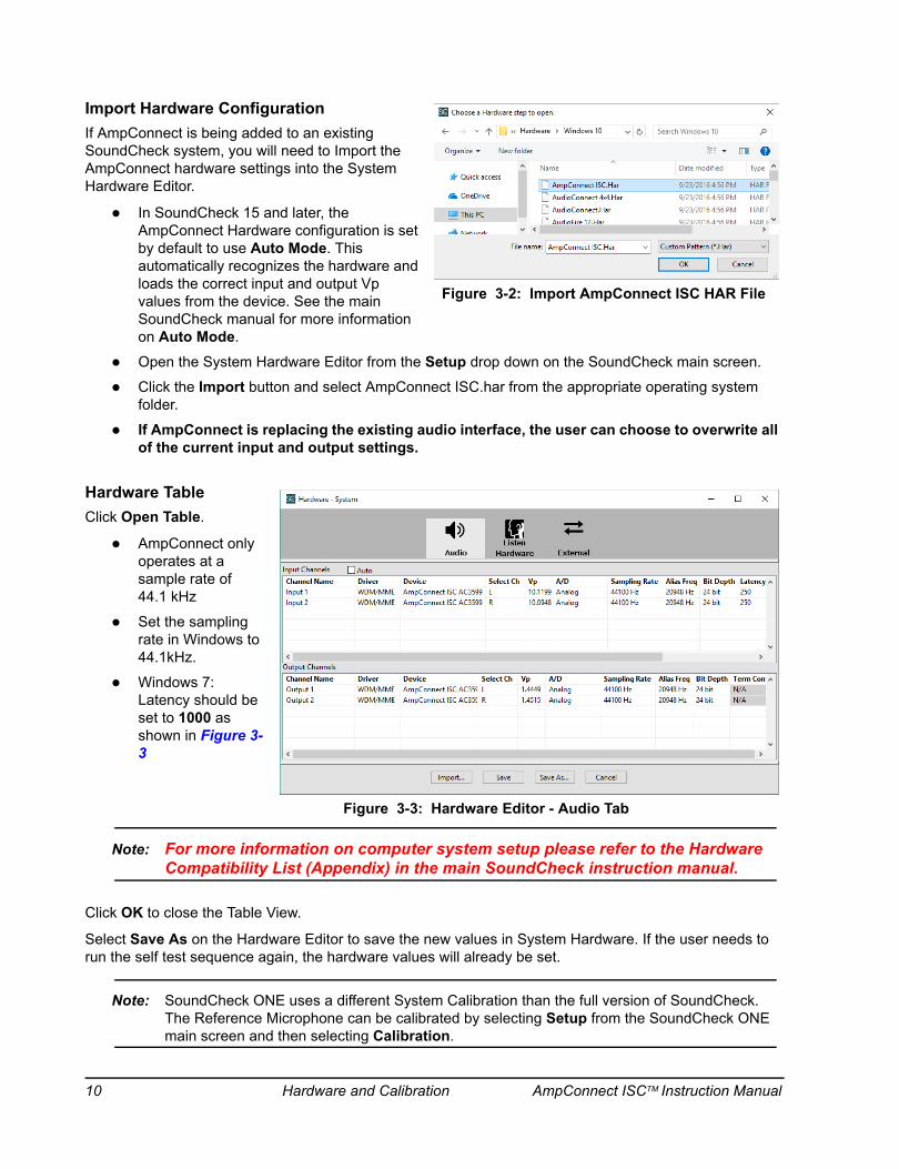
Import Hardware ConfigurationIf AmpConnect is being added to an existing SoundCheck system, you will need to Import the AmpConnect hardware settings into the System Hardware Editor.
In SoundCheck 15 and later, the AmpConnect Hardware configuration is set by default to use Auto Mode. This automatically recognizes the hardware and loads the correct input and output Vp values from the device. See the main SoundCheck manual for more information on Auto Mode.
Open the System Hardware Editor from the Setup drop down on the SoundCheck main screen.
Click the Import button and select AmpConnect ISC.har from the appropriate operating system folder.
If AmpConnect is replacing the existing audio interface, the user can choose to overwrite all of the current input and output settings.
Hardware TableClick Open Table.
AmpConnect only operates at a sample rate of 44.1 kHz
Set the sampling rate in Windows to 44.1kHz.
Windows 7: Latency should be set to 1000 as shown in Figure 3-3
Note: For more information on computer system setup please refer to the Hardware Compatibility List (Appendix) in the main SoundCheck instruction manual.
Click OK to close the Table View.
Select Save As on the Hardware Editor to save the new values in System Hardware. If the user needs to run the self test sequence again, the hardware values will already be set.
Note: SoundCheck ONE uses a different System Calibration than the full version of SoundCheck. The Reference Microphone can be calibrated by selecting Setup from the SoundCheck ONE main screen and then selecting Calibration.
Figure 3-2: Import AmpConnect ISC HAR File
Figure 3-3: Hardware Editor - Audio Tab
10 Hardware and Calibration AmpConnect ISCTM Instruction Manual

AmpConnect ISC Hardware ConfigurationThe AmpConnect ISC Hardware settings are included in the default steps with SoundCheck.
SoundCheck 11 (and higher) will need to import the AmpConnect ISC settings as shown in Import Hardware Configuration on page 10. The AmpConnect.Har configuration file is preset with the Inputs and Outputs that would normally be used in a SoundCheck sequence.
SC One Hardware ConfigurationThe default latency in the SC ONE hardware configuration changed after version 11.0.
SC One users should make sure the hardware configuration settings are updated to the current values. See Hardware Table on page 10.
SoundCheck System Calibration
Important! As of SoundCheck 11, Calibration is a “System Level” configuration. It is unique to a specific SoundCheck system and is used by all sequences. Individual Calibration Steps are no longer used. Settings from these steps can be imported in the Calibration Configuration Editor. Refer to the main SoundCheck manual for more information.
Figure 3-4 shows the Calibration Editor with the default Signal Paths used in SoundCheck.
Amp Ch 1 uses the AmpConnect.dat calibrated device. There is only one amp channel.
Headphone Amp L and R use the Headphone Amp.dat calibrated device.
Figure 3-4: System Calibration
AmpConnect ISCTM Instruction Manual Hardware and Calibration 11
Self Test SequenceAfter the Hardware and Calibration configurations are complete, you can run one of the self test sequences to verify the performance of your AmpConnect.
These sequences are found in: C:\SoundCheck x.x\Sequences\Calibration\
AmpConnect Self Test.sqc - Requires optional module 2006 - Time Selective Response
AmpConnect Self Test Stepped Sine.sqc - Included for users who do not have Time Selective Response
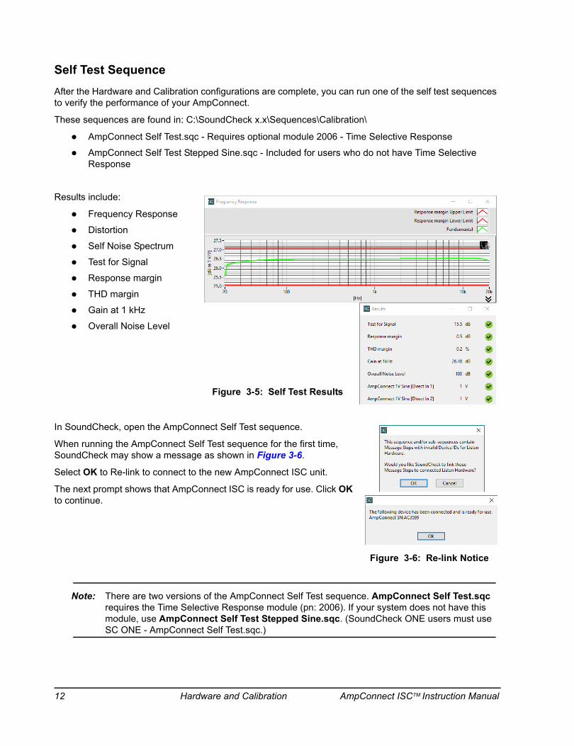
Results include:
Frequency Response
Distortion
Self Noise Spectrum
Test for Signal
Response margin
THD margin
Gain at 1 kHz
Overall Noise Level
In SoundCheck, open the AmpConnect Self Test sequence.
When running the AmpConnect Self Test sequence for the first time, SoundCheck may show a message as shown in Figure 3-6.
Select OK to Re-link to connect to the new AmpConnect ISC unit.
The next prompt shows that AmpConnect ISC is ready for use. Click OK to continue.
Note: There are two versions of the AmpConnect Self Test sequence. AmpConnect Self Test.sqc requires the Time Selective Response module (pn: 2006). If your system does not have this module, use AmpConnect Self Test Stepped Sine.sqc. (SoundCheck ONE users must use SC ONE - AmpConnect Self Test.sqc.)
Figure 3-5: Self Test Results
Figure 3-6: Re-link Notice
12 Hardware and Calibration AmpConnect ISCTM Instruction Manual

Amplifier CalibrationThe gain of AmpConnect is fixed at 26.4 dB. This is the value in the stock System Calibration Configuration. The mono power amplifier in AmpConnect ISC can be calibrated in SoundCheck if a more precise value is required. Since it is a mono amp, only one channel is required for calibration.
AmpConnect ISC SettingsThe Front Panel of AmpConnect ISC must be set as shown in Figure 3-7.
No external connects are required
Panel is selected on the AmpConnect front panel
Ref and DUT Inputs - Bias and Gain settings not applicable
Output Select Channel 1
Select Amp - This routes the amp to a 20 dB attenuator, then to internal audio interface input Channel 1
Amplifier output on AmpConnect ISC should be Off (since it is internally connected to audio interface input 1) or disconnect any external load
Important! The Sensitivity of the “Direct In 1” channel in the SoundCheck System Calibration must be Unity Gain (0 dB). Figure 3-8 shows Direct In 1 selected as the Input Signal Channel.
INPUT
ReferenceLevel
DUTLevel
NoneVoltageIEPE
+40dB+30dB+20dB+10dB
0dB-10dB-20dB
Bias Gain Setup Source Select
Channel 1Channel 2
Output AOutput B
Level
CONTROL OUTPUT AMPLIFIER
SetupEnable
USBPanel
Digital I/O
Bit 6Bit 5Bit 4Bit 3Bit 2Bit 1Bit 0
Bit 7
Z-HighZ-LowAmp
ReferenceDUT
1V Sine
AmpConnect ISC™
Headphone
Figure 3-7: Front Panel Settings
AmpConnect ISCTM Instruction Manual Hardware and Calibration 13
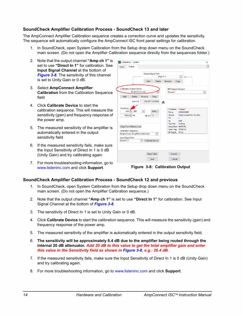
SoundCheck Amplifier Calibration Process - SoundCheck 13 and laterThe AmpConnect Amplifier Calibration sequence creates a correction curve and updates the sensitivity. The sequence will automatically configure the AmpConnect ISC front panel settings for calibration.
1. In SoundCheck, open System Calibration from the Setup drop down menu on the SoundCheck main screen. (Do not open the Amplifier Calibration sequence directly from the sequences folder.)
2. Note that the output channel “Amp ch 1” is set to use “Direct In 1” for calibration. See Input Signal Channel at the bottom of Figure 3-8. The sensitivity of this channel is set to Unity Gain or 0 dB.
3. Select AmpConnect Amplifier Calibration from the Calibration Sequence field
4. Click Calibrate Device to start the calibration sequence. This will measure the sensitivity (gain) and frequency response of the power amp.
5. The measured sensitivity of the amplifier is automatically entered in the output sensitivity field
6. If the measured sensitivity fails, make sure the Input Sensitivity of Direct In 1 is 0 dB (Unity Gain) and try calibrating again.
7. For more troubleshooting information, go to www.listeninc.com and click Support.
SoundCheck Amplifier Calibration Process - SoundCheck 12 and previous1. In SoundCheck, open System Calibration from the Setup drop down menu on the SoundCheck
main screen. (Do not open the Amplifier Calibration sequence.)
2. Note that the output channel “Amp ch 1” is set to use “Direct In 1” for calibration. See Input Signal Channel at the bottom of Figure 3-8.
3. The sensitivity of Direct In 1 is set to Unity Gain or 0 dB.
4. Click Calibrate Device to start the calibration sequence. This will measure the sensitivity (gain) and frequency response of the power amp.
5. The measured sensitivity of the amplifier is automatically entered in the output sensitivity field.
6. The sensitivity will be approximately 6.4 dB due to the amplifier being routed through the internal 20 dB attenuator. Add 20 dB to this value to get the total amplifier gain and enter this value in the Sensitivity field as shown in Figure 3-8, e.g.: 26.4 dB.
7. If the measured sensitivity fails, make sure the Input Sensitivity of Direct In 1 is 0 dB (Unity Gain) and try calibrating again.
8. For more troubleshooting information, go to www.listeninc.com and click Support.
Figure 3-8: Calibration Output
14 Hardware and Calibration AmpConnect ISCTM Instruction Manual

Microphone CalibrationThe REF and/or DUT microphone inputs should be calibrated when using either as an input for a reference microphone.
This procedure allows the user to check a reference microphone’s sensitivity against the microphone manufacturer’s specifications.
1. Open the Calibration Editor and select the Input tab. The Calibration Sequence should be set to Microphone.
2. Click Calibrate.
3. Select your calibrator model # from the pull-down menu or select Other Calibrator and enter the acoustic calibrator’s reference level and frequency.
The microphone calibrator's reference level should be indicated in its specifications as a given dBSPL value (relative to 20 µPa) at a reference frequency.
e.g., for the Brüel & Kjær Type 4231 Acoustic Calibrator:
Sound Pressure Level: 94.00 dB ± 0.20 dB
Frequency: 1000 Hz ± 0.1%
4. Note the gain or attenuation value, in dB, from the AmpConnect ISC channel settings that the reference microphone is connected to. Enter this value in the Pre-Gain numeric field of the Calibration Step.
5. Select your measurement microphone model number from the drop down menu. If your microphone is not listed in the drop down menu, choose Add New Mic. Refer to the SoundCheck Instruction Manual for more information.
6. Place the acoustic calibrator on the reference microphone and click Calibrate to measure its sensitivity.
The measured sensitivity of the reference microphone is displayed under Measured Sensitivity in mV/Pa after clicking Calibrate. If the measured sensitivity is outside the manufacturer’s specifications, a flashing FAILED message will appear. Check first to see if the connections are correct or if the calibrator is turned on before assuming something is wrong with the microphone.
The FAILED message can also appear if the Calibrator’s frequency is not correct. If a Reference Frequency of 1000 Hz is entered, but the Calibrator’s actual frequency is 1008 Hz, the Calibration may Fail. To verify the Calibrator’s frequency, use the Spectrum Analyzer under the Operate menu.
The meter on the right side indicates the corresponding dB level relative to 1 Volt per Pascal. If it varies by a few tenths of a dB from the last calibration measurement, do not be alarmed, this is normal. If it varies by more than 1 dB or failed the sensitivity test, the microphone should be checked by a qualified calibration lab.
Figure 3-9: Microphone Calibration
AmpConnect ISCTM Instruction Manual Hardware and Calibration 15

page intentionally left blank
16 Hardware and Calibration AmpConnect ISCTM Instruction Manual
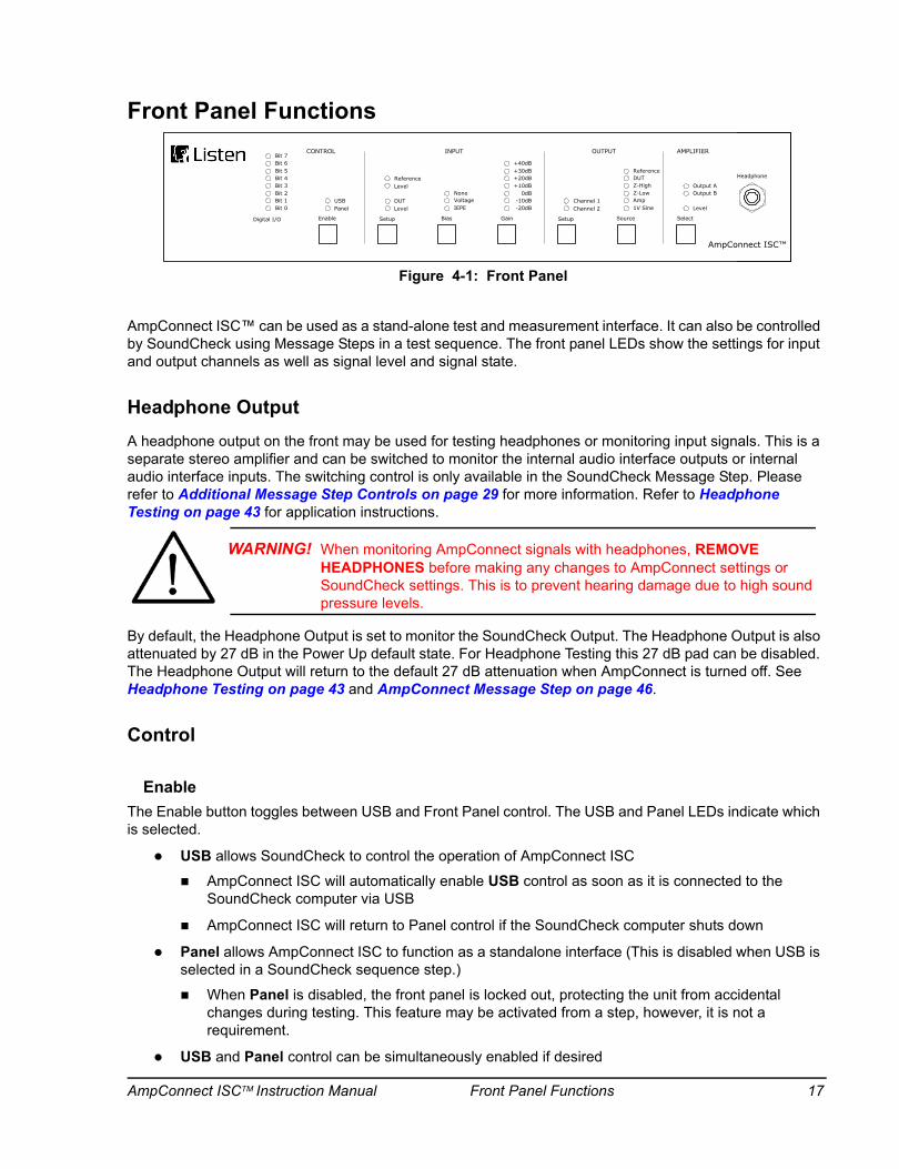
Front Panel Functions
AmpConnect ISC™ can be used as a stand-alone test and measurement interface. It can also be controlled by SoundCheck using Message Steps in a test sequence. The front panel LEDs show the settings for input and output channels as well as signal level and signal state.
Headphone OutputA headphone output on the front may be used for testing headphones or monitoring input signals. This is a separate stereo amplifier and can be switched to monitor the internal audio interface outputs or internal audio interface inputs. The switching control is only available in the SoundCheck Message Step. Please refer to Additional Message Step Controls on page 29 for more information. Refer to Headphone Testing on page 43 for application instructions.
By default, the Headphone Output is set to monitor the SoundCheck Output. The Headphone Output is also attenuated by 27 dB in the Power Up default state. For Headphone Testing this 27 dB pad can be disabled. The Headphone Output will return to the default 27 dB attenuation when AmpConnect is turned off. See Headphone Testing on page 43 and AmpConnect Message Step on page 46.
Control
EnableThe Enable button toggles between USB and Front Panel control. The USB and Panel LEDs indicate which is selected.
USB allows SoundCheck to control the operation of AmpConnect ISC
AmpConnect ISC will automatically enable USB control as soon as it is connected to the SoundCheck computer via USB
AmpConnect ISC will return to Panel control if the SoundCheck computer shuts down
Panel allows AmpConnect ISC to function as a standalone interface (This is disabled when USB is selected in a SoundCheck sequence step.)
When Panel is disabled, the front panel is locked out, protecting the unit from accidental changes during testing. This feature may be activated from a step, however, it is not a requirement.
USB and Panel control can be simultaneously enabled if desired
INPUT
ReferenceLevel
DUTLevel
NoneVoltageIEPE
+40dB+30dB+20dB+10dB
0dB-10dB-20dB
Bias Gain Setup Source Select
Channel 1Channel 2
Z-HighZ-LowAmp
ReferenceDUT
1V Sine
Output AOutput B
Level
CONTROL OUTPUT AMPLIFIER
SetupEnable
USBPanel
Digital I/O
Bit 6Bit 5Bit 4Bit 3Bit 2Bit 1Bit 0
Bit 7
AmpConnect ISC™
Headphone
Figure 4-1: Front Panel
WARNING! When monitoring AmpConnect signals with headphones, REMOVE HEADPHONES before making any changes to AmpConnect settings or SoundCheck settings. This is to prevent hearing damage due to high sound pressure levels.
AmpConnect ISCTM Instruction Manual Front Panel Functions 17

Panel Control
Important! The default power up state is user defined. Thirty seconds after the front panel settings have been changed, the new settings are stored and will be used as the new default state the next time the unit is powered on.
The initial power up default settings from Listen, Inc., are those most commonly used for loudspeaker testing:
Digital I/O: all Bits are Low (LEDs off). (Digital I/O is not available when used as a stand-alone interface)
Input Reference: Mic Bias set to Voltage with +20 dB of gain
Input DUT: Not selected since it is not used in for loudspeaker testing [DUT default settings]
Output Channel 1: Reference Mic
Output Channel 2: Z-Low
Amplifier: Output routed to Output A
USB ControlUSB control of front panel functions through a SoundCheck sequence step
When USB is selected in a SoundCheck sequence step, the Front Panel controls are disabled to prevent accidental changes
Digital I/O8 bits of digital I/O that can be written and read directly in SoundCheck
Used to control relay boards and switches, e.g. footswitch for Start and Stop
Communicate with PLCs in automated production lines
Receive TTL signals from other test equipment
See Digital I/O Connections on page 33
Digital I/O StatesBits can be used as either input or output. The state of the Bit is indicated by the LEDs:
LED off - Bit is low
LED on - Bit is high
When set to Read - In the AmpConnect message step, you click on the Bit LED to set the state: On = High, Off = Low. See General rules on page 33.
The Digital I/O function can only be used when AmpConnect ISC is controlled by SoundCheck through USB
18 Front Panel Functions AmpConnect ISCTM Instruction Manual
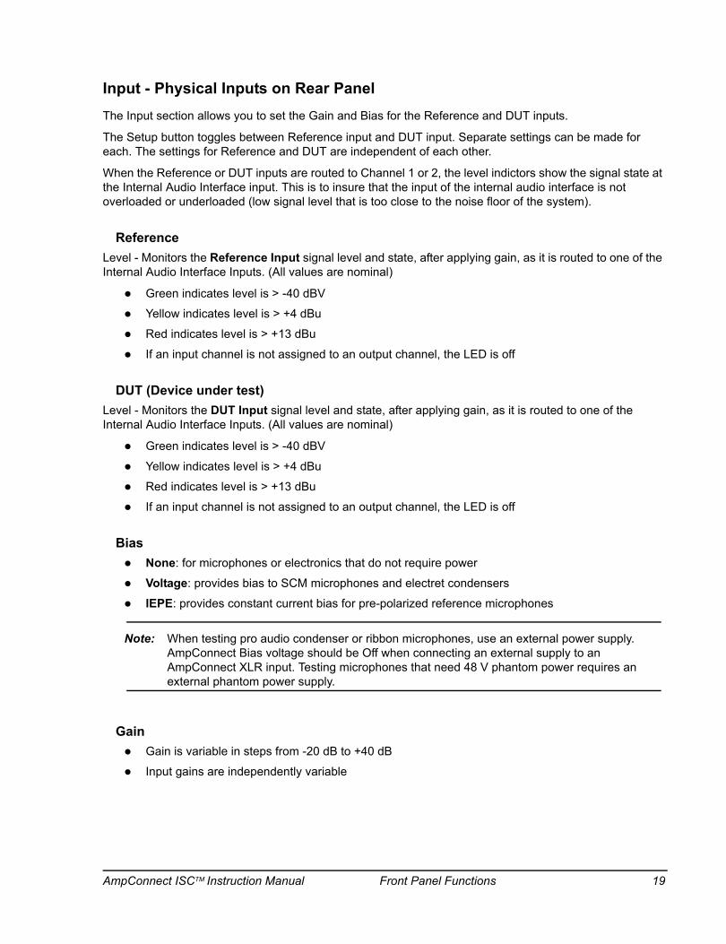
Input - Physical Inputs on Rear PanelThe Input section allows you to set the Gain and Bias for the Reference and DUT inputs.
The Setup button toggles between Reference input and DUT input. Separate settings can be made for each. The settings for Reference and DUT are independent of each other.
When the Reference or DUT inputs are routed to Channel 1 or 2, the level indictors show the signal state at the Internal Audio Interface input. This is to insure that the input of the internal audio interface is not overloaded or underloaded (low signal level that is too close to the noise floor of the system).
ReferenceLevel - Monitors the Reference Input signal level and state, after applying gain, as it is routed to one of the Internal Audio Interface Inputs. (All values are nominal)
Green indicates level is > -40 dBV
Yellow indicates level is > +4 dBu
Red indicates level is > +13 dBu
If an input channel is not assigned to an output channel, the LED is off
DUT (Device under test)Level - Monitors the DUT Input signal level and state, after applying gain, as it is routed to one of the Internal Audio Interface Inputs. (All values are nominal)
Green indicates level is > -40 dBV
Yellow indicates level is > +4 dBu
Red indicates level is > +13 dBu
If an input channel is not assigned to an output channel, the LED is off
BiasNone: for microphones or electronics that do not require power
Voltage: provides bias to SCM microphones and electret condensers
IEPE: provides constant current bias for pre-polarized reference microphones
Note: When testing pro audio condenser or ribbon microphones, use an external power supply. AmpConnect Bias voltage should be Off when connecting an external supply to an AmpConnect XLR input. Testing microphones that need 48 V phantom power requires an external phantom power supply.
GainGain is variable in steps from -20 dB to +40 dB
Input gains are independently variable
AmpConnect ISCTM Instruction Manual Front Panel Functions 19
Output - Physical Input Routing to Internal Audio InterfaceThis allows you to route the Physical Input Signals and Internal Source Signals to the inputs of the Internal Audio Interface. Settings for Channels 1 and 2 are independent of each other. The user can choose which signals are routed to each from the Front Panel or via USB control.
Any of the following source signals can be routed to Channel 1 or 2 of the internal audio interface:
Reference (Microphone) Input: Signal from the Reference microphone input
DUT (Microphone) Input: Signal from the DUT microphone input
Z-High: The voltage across a 1 Ω current reference resistor (for loudspeaker impedance test)
Output signal is 1 Volt/Amp
An alternate resistor value is available as a factory installed option from Listen, Inc.
Z-Low: The voltage across a 0.1 Ω current reference resistor (for loudspeaker impedance test)
Output signal is 100 mVolt/Amp
Fixed value - cannot be changed
Amp: the output voltage of the power amplifier, attenuated by 20 dB (x 0.1)
The power amp output can be routed to an internal audio interface input when calibrating the amp
Only one internal audio interface input at a time may use this source
Output Impedance: Actively minimized to nearly 0 Ω
1V Sine: a reference 1 Volt, 1 kHz sine
Constant signal generated by AmpConnect ISC
Route to either internal audio interface input in order to test audio interface connections and settings
Cannot be routed to amplifier output
Quiet: Output channel is defeated (All source LEDs are set to Off). If AmpConnect ISC is accidentally disconnected from USB or if the computer is shut off, AmpConnect ISC will automatically switch to Quiet. The power amplifier outputs are also set to Off. This is to minimize transients. Re-enable the channel outputs and power amp outputs by re-selecting them.
20 Front Panel Functions AmpConnect ISCTM Instruction Manual
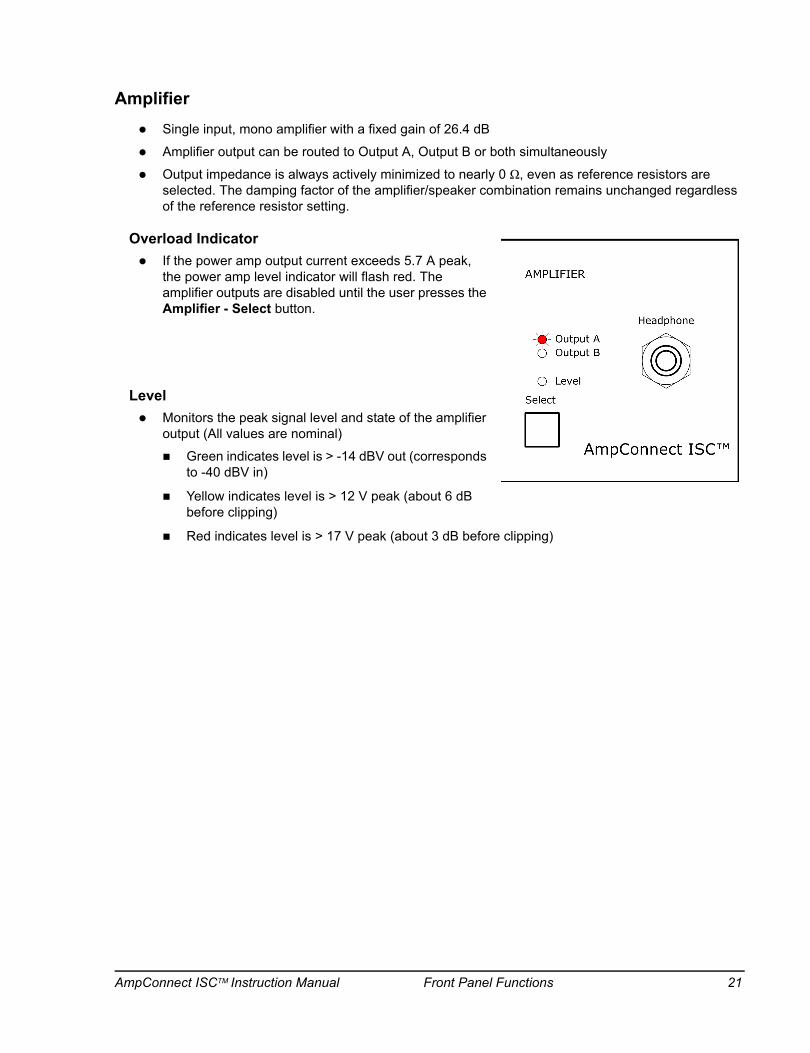
AmplifierSingle input, mono amplifier with a fixed gain of 26.4 dB
Amplifier output can be routed to Output A, Output B or both simultaneously
Output impedance is always actively minimized to nearly 0 Ω, even as reference resistors are selected. The damping factor of the amplifier/speaker combination remains unchanged regardless of the reference resistor setting.
Overload IndicatorIf the power amp output current exceeds 5.7 A peak, the power amp level indicator will flash red. The amplifier outputs are disabled until the user presses the Amplifier - Select button.
LevelMonitors the peak signal level and state of the amplifier output (All values are nominal)
Green indicates level is > -14 dBV out (corresponds to -40 dBV in)
Yellow indicates level is > 12 V peak (about 6 dB before clipping)
Red indicates level is > 17 V peak (about 3 dB before clipping)
AmpConnect ISCTM Instruction Manual Front Panel Functions 21

page intentionally left blank
22 Front Panel Functions AmpConnect ISCTM Instruction Manual
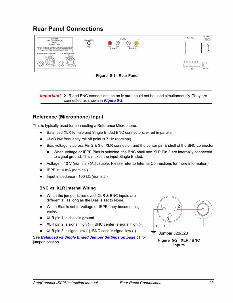
Rear Panel Connections
Important! XLR and BNC connections on an input should not be used simultaneously. They are connected as shown in Figure 5-2.
Reference (Microphone) InputThis is typically used for connecting a Reference Microphone.
Balanced XLR female and Single Ended BNC connectors, wired in parallel
-3 dB low frequency roll off point is 7 Hz (nominal)
Bias voltage is across Pin 2 & 3 of XLR connector, and the center pin & shell of the BNC connector
When Voltage or IEPE Bias is selected, the BNC shell and XLR Pin 3 are internally connected to signal ground. This makes the input Single Ended.
Voltage = 10 V (nominal) (Adjustable: Please refer to Internal Connections for more information)
IEPE = 10 mA (nominal)
Input impedance - 100 kΩ (nominal)
BNC vs. XLR Internal Wiring
When the jumper is removed, XLR & BNC inputs are differential, as long as the Bias is set to None.
When Bias is set to Voltage or IEPE, they become single ended.
XLR pin 1 is chassis ground
XLR pin 2 is signal high (+), BNC center is signal high (+)
XLR pin 3 is signal low (-), BNC case is signal low (-)
See Balanced vs Single Ended Jumper Settings on page 51 for jumper location.
PUSH
CAUTIONRISK OF ELECTRICAL
SHOCKDO NOT OPEN
CAUTION: TO REDUCE THE RISK OF ELECTRICAL SHOCK, DO NOTREMOVE COVER. NO USER-SERVICABLE PARTS INSIDE. REFER
SERVICING TO QUALIFIED SERVICE PERSONNEL.
Reference (Microphone) DUT (Microphone)
USB 2.0DigitalI/O
AC Rating:110-240V
50-60Hz, 2AFuse: T2.0A
Bit
0Bit
1Bit
2Bit
3Bit
4Bit
5Bit
6Bit
7+
5VRet
.
- Output B ++ Output A -
PUSH
Amplifier
Red Black Black Yellow
Chassis GND
Figure 5-1: Rear Panel
1 2
3
Jumper J20/J28Figure 5-2: XLR / BNC
Inputs
AmpConnect ISCTM Instruction Manual Rear Panel Connections 23
DUT (Microphone) InputThis connection can be used for connecting a “Device Under Test” Microphone. This connection is used typically for microphone testing.
Features are the same as the Reference Input
Note: In cases where a DC Bias Voltage could damage a mic or power supply, e.g.: pro audio condenser or ribbon microphones, use an external power supply. AmpConnect Bias voltage should be OFF. Testing microphones that need 48 V phantom power requires an external phantom power supply.
AmplifierThe internal audio interface Left Output is directly connected to the mono power amplifier input.
Amplifier Output A
Connects to a transducer via the binding post connectors.
Note: There is only one, mono power amp channel in AmpConnect ISC. This amp channel can be switched to either Output A, Output B or A + B.
Amplifier Output B
Connects to a second transducer via the binding post connectors.
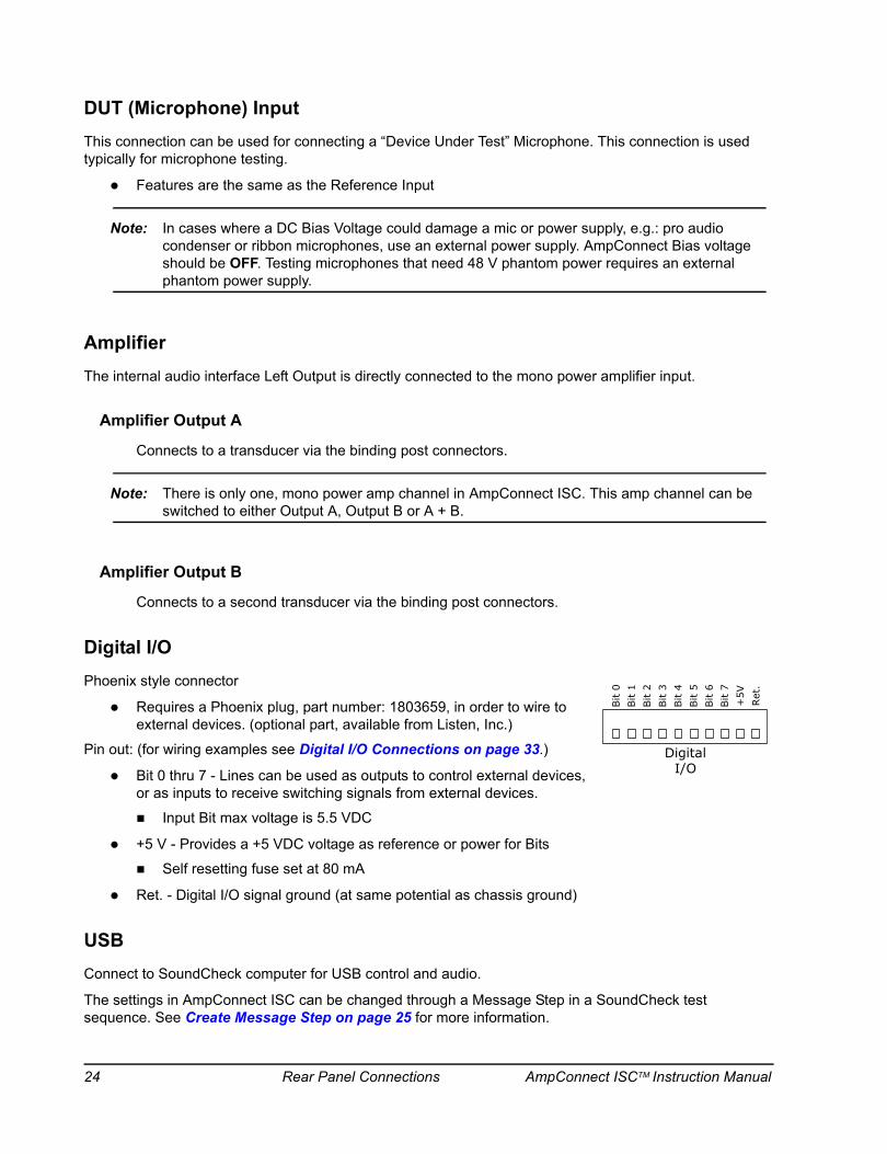
Digital I/OPhoenix style connector
Requires a Phoenix plug, part number: 1803659, in order to wire to external devices. (optional part, available from Listen, Inc.)
Pin out: (for wiring examples see Digital I/O Connections on page 33.)
Bit 0 thru 7 - Lines can be used as outputs to control external devices, or as inputs to receive switching signals from external devices.
Input Bit max voltage is 5.5 VDC
+5 V - Provides a +5 VDC voltage as reference or power for Bits
Self resetting fuse set at 80 mA
Ret. - Digital I/O signal ground (at same potential as chassis ground)
USBConnect to SoundCheck computer for USB control and audio.
The settings in AmpConnect ISC can be changed through a Message Step in a SoundCheck test sequence. See Create Message Step on page 25 for more information.
DigitalI/O
Bit
0Bit
1Bit
2Bit
3Bit
4Bit
5Bit
6Bit
7+
5VR
et.
24 Rear Panel Connections AmpConnect ISCTM Instruction Manual
USB Control Via SoundCheck
AmpConnect ISC is fully controllable via a SoundCheck Message Step. This allows adjustments of parameters such as gain and signal routing to be included in test sequences. All Front Panel settings can be changed via USB during the run of a test sequence. An eight-bit digital I/O port provides digital control and/or status monitoring of external devices for operator feedback, test fixture control, etc. Digital I/O is only accessed by USB through SoundCheck. The following example shows how to use a Message Step in SoundCheck to control AmpConnect ISC. (AmpConnect ISC must be enabled in the Hardware Step. See Hardware Configuration on page 9.)
Important! The default Message Step included with SoundCheck, “AmpConnect.MES”, is “Read Only“ and should not be modified. It is reserved for use in SoundCheck ONE.
Note: In SoundCheck ONE, the user does not have access to creating a new Message Step. Only the settings in the existing step can be changed. SoundCheck ONE users should skip to AmpConnect Message Step on page 26.
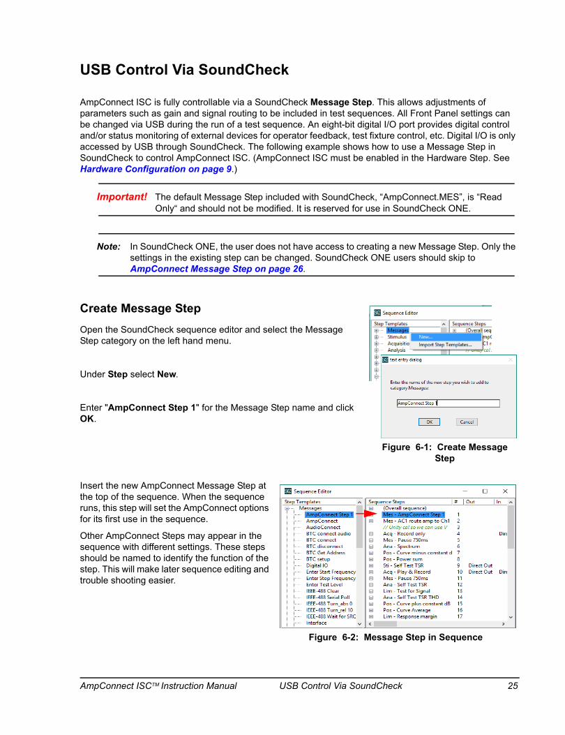
Create Message StepOpen the SoundCheck sequence editor and select the Message Step category on the left hand menu.
Under Step select New.
Enter "AmpConnect Step 1" for the Message Step name and click OK.
Insert the new AmpConnect Message Step at the top of the sequence. When the sequence runs, this step will set the AmpConnect options for its first use in the sequence.
Other AmpConnect Steps may appear in the sequence with different settings. These steps should be named to identify the function of the step. This will make later sequence editing and trouble shooting easier.
Figure 6-1: Create Message Step
Figure 6-2: Message Step in Sequence
AmpConnect ISCTM Instruction Manual USB Control Via SoundCheck 25

Note: AmpConnect settings can be changed during the run of a test sequence. This will require individual Message Steps at various points in the sequence. Prior to SoundCheck 12, only the Device ID field is Sequence-specific (Blue Field). Changes to this item will appear only in the sequence being edited. All other items are Step-Specific (Black Fields). Changes to these fields will appear in all sequences that use this step. As of SoundCheck 12, all fields in step editors are Sequence-Specific.
AmpConnect Message StepOpen the AmpConnect Message Step from the Active Sequence in the right hand section of the editor, as shown in Figure 6-2.
Message Title - This is the text that will be in the top of the step window as it is run.
Message - The example in Figure 6-3 shows that the Message Step is set to AmpConnect.
Device ID - The user can select which AmpConnect should be used, if multiple AmpConnects are on the system.
Configure AmpConnect (Configure Listen Hardware) - Set the front panel settings of AmpConnect (see below)
Settings - The user selects the Pass/Fail state the step will yield in the Results section of the Memory List.
Wait - Allows the user to set a time period for the step to pause the run of the sequence. This allows for “switch closure times” associated with external devices connected to the Digital I/O of AmpConnect.
Apply - Click Apply to switch AmpConnect ISC to the new settings from Configure AmpConnect without having to run the sequence. This is useful for testing the settings.
Note: SoundCheck ONE users will only have access to the default AmpConnect Step. To modify the settings, click on Setup from the SoundCheck ONE main screen. Then click on Messages as shown in Figure 6-4. Click on Configure Listen Hardware to change settings.
Figure 6-3: AmpConnect Settings
Figure 6-4: SC ONE AmpConnect Message
26 USB Control Via SoundCheck AmpConnect ISCTM Instruction Manual
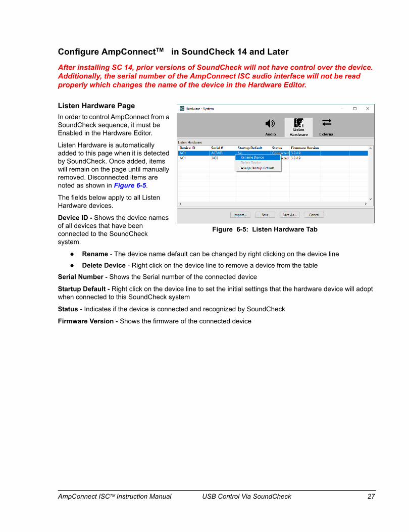
Configure AmpConnect in SoundCheck 14 and Later
After installing SC 14, prior versions of SoundCheck will not have control over the device. Additionally, the serial number of the AmpConnect ISC audio interface will not be read properly which changes the name of the device in the Hardware Editor.
Listen Hardware PageIn order to control AmpConnect from a SoundCheck sequence, it must be Enabled in the Hardware Editor.
Listen Hardware is automatically added to this page when it is detected by SoundCheck. Once added, items will remain on the page until manually removed. Disconnected items are noted as shown in Figure 6-5.
The fields below apply to all Listen Hardware devices.
Device ID - Shows the device names of all devices that have been connected to the SoundCheck system.
Rename - The device name default can be changed by right clicking on the device line
Delete Device - Right click on the device line to remove a device from the table
Serial Number - Shows the Serial number of the connected device
Startup Default - Right click on the device line to set the initial settings that the hardware device will adopt when connected to this SoundCheck system
Status - Indicates if the device is connected and recognized by SoundCheck
Firmware Version - Shows the firmware of the connected device
TM
Figure 6-5: Listen Hardware Tab
AmpConnect ISCTM Instruction Manual USB Control Via SoundCheck 27
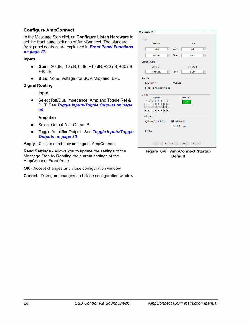
Configure AmpConnectIn the Message Step click on Configure Listen Hardware to set the front panel settings of AmpConnect. The standard front panel controls are explained in Front Panel Functions on page 17.
Inputs
Gain: -20 dB, -10 dB, 0 dB, +10 dB, +20 dB, +30 dB, +40 dB
Bias: None, Voltage (for SCM Mic) and IEPE
Signal Routing
Input
Select Ref/Dut, Impedance, Amp and Toggle Ref & DUT. See Toggle Inputs/Toggle Outputs on page 30.
Amplifier
Select Output A or Output B
Toggle Amplifier Output - See Toggle Inputs/Toggle Outputs on page 30.
Apply - Click to send new settings to AmpConnect
Read Settings - Allows you to update the settings of the Message Step by Reading the current settings of the AmpConnect Front Panel
OK - Accept changes and close configuration window
Cancel - Disregard changes and close configuration window
Figure 6-6: AmpConnect Startup Default
28 USB Control Via SoundCheck AmpConnect ISCTM Instruction Manual

Configure AmpConnect in SoundCheck 13 and Previous VersionsClick on Configure AmpConnect to set the front panel settings of AmpConnect ISC.
Read Settings - Allows the user to update the settings of the Message Step by Reading the current settings of the AmpConnect ISC Front Panel.
Apply - Click to send new settings to AmpConnect ISC.
OK - Accept changes and close configuration window.
Cancel - Disregard changes and close configuration window.
View Settings ChangesThe front panel of AmpConnect can only show the settings for one input and one output at a time.
On the physical front panel of AmpConnect, click Enable to turn on Panel (Panel Control)
Click the Select button in the Input section to switch between Reference or DUT
Click the Select button in the Output section to switch between Channels 1 and 2
Click Apply in the Message Step. You will see that your changes are being implemented as you use the Select buttons to toggle between channels.
Microphone Bias “On Time”If you turn the microphone bias voltage on during the run of a sequence, you may need to set a “Wait” period before proceeding to an Acquisition Step. The microphone connected to the Ref or Dut input may require 2 seconds (approx) to fully turn on after voltage is applied. You must allow for the microphone turn on time before an Acquisition Step using that mic is run in the sequence. See Sequence Editor > Step Configuration in the SoundCheck manual for instructions on setting “Wait time” in a Message Step.
Additional Message Step ControlsThe standard front panel controls are available in the Message Step. These are explained in Front Panel Functions on page 17. In addition to the standard front panel controls, Configure AmpConnect also includes:
Control - Digital I/O (must be set to USB)Bit 0 thru 7: Shows the state that the Bit expects to see when set to Read. If the actual state of the input agrees with the setting, the step result will be “Pass“. If it does not agree, the result will be “Fail“. When set to write, this is the state that the Bit will change to when the Message Step runs in the sequence.
Figure 6-7: AmpConnect ISC Message Step in SC13
AmpConnect ISCTM Instruction Manual USB Control Via SoundCheck 29
Toggle Inputs/Toggle OutputsThe Toggle control can be used to switch the Microphone Input and Amplifier Output as a test sequence runs in Continuous or Loop operation. This can be used to test a loudspeaker on one test fixture while setting up a different speaker on another fixture. (The fixtures and test microphones should be identical.)
Toggle Inputs (Ch.1): Switches so that on the first pass of the sequence, Channel 1 uses the Reference Microphone Input and the second pass uses the DUT Microphone Input. (Output section.) This works on Channel 1 only.
Toggle Outputs: Switches so that the first pass of the sequence uses Amplifier Output A and the second pass uses Amplifier Output B.
Headphone SettingsInserting the Message Step turns off the Headphone Output 27 dB pad (power up default)
The Headphone Output will return to the default 27 dB attenuation when AmpConnect is turned off
SoundCheck Output - Sends the SoundCheck Stimulus to the headphone output
Input Monitor - Allows you to monitor the Left Input of the internal audio interface
Gain - Allows you to adjust the level of the Headphone Out. The default setting is 0 dB. (Available only when Input Monitor is selected.)
Gain is greyed out when SoundCheck Output is selected
Mute - Mute signal to headphone output
Custom Step ConversionSoundCheck 9 users will need to upgrade to SoundCheck 11.x (or later) to control AmpConnect ISC. The Custom Step from SoundCheck 9 will need to be re-created as a Message Step in SoundCheck 11.x and up.
Please use the following procedure.
1. Open the AmpConnect Custom Step(s) in SoundCheck 9.
2. Write down the settings for the step. (See User Setup Notes on page 42 for a blank front panel drawing, which makes notation of settings easier.)
3. In SoundCheck 11(and later), configure the System Hardware Configuration for AmpConnect. See AmpConnect in the Hardware Chapter of the main SoundCheck manual.
4. Make a new Message Step in SoundCheck and enter the settings from the front panel notation.
5. SoundCheck 10 (and later) will not open AmpConnect Custom Steps.
30 USB Control Via SoundCheck AmpConnect ISCTM Instruction Manual
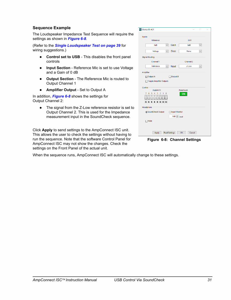
Sequence ExampleThe Loudspeaker Impedance Test Sequence will require the settings as shown in Figure 6-8.
(Refer to the Single Loudspeaker Test on page 39 for wiring suggestions.)
Control set to USB - This disables the front panel controls
Input Section - Reference Mic is set to use Voltage and a Gain of 0 dB
Output Section - The Reference Mic is routed to Output Channel 1
Amplifier Output - Set to Output A
In addition, Figure 6-8 shows the settings for Output Channel 2:
The signal from the Z-Low reference resistor is set to Output Channel 2. This is used for the Impedance measurement input in the SoundCheck sequence.
Click Apply to send settings to the AmpConnect ISC unit. This allows the user to check the settings without having to run the sequence. Note that the software Control Panel for AmpConnect ISC may not show the changes. Check the settings on the Front Panel of the actual unit.
When the sequence runs, AmpConnect ISC will automatically change to these settings.
Figure 6-8: Channel Settings
AmpConnect ISCTM Instruction Manual USB Control Via SoundCheck 31

page intentionally left blank
AmpConnect ISCTM Instruction Manual USB Control Via SoundCheck 32
Digital I/O Connections
Reading External Switch Closures
The Digital I/O (DIO) of AmpConnect ISC can read external TTL voltage levels and switch closures in a SoundCheck test sequence. DIO settings are made in an AmpConnect ISC Message Step used in the sequence. The DIO settings of AmpConnect ISC can only be accessed through a SoundCheck Message Step. See AmpConnect ISC Message Step on page 37
The DIO layout is 8 Bit; 0 thru 7, with the option to set any Bit as Read or Write.
When the Bit Light is On, the Bit is set High. When Off, the Bit is set Low.
The Read/Write state of the Bit determines if it acts an Output or an Input. (See General Rules below.)
Note: Individual AmpConnect ISC Message Steps are required in a SoundCheck sequence to perform various DIO operations. Each step can have different settings including different Bit configurations.
Note: Digital I/O control is not available in SoundCheck ONE.
General rulesBits are at ground when set Low (LED Off)
Bits are at +5 V when set High (LED On)
This corresponds to the Front Panel LEDs and software control settings
When set to Read (configured as an input), the Bit is pulled high through an internal 100K resistor
Bits set to Read will act as Inputs. In the AmpConnect Message Step, click on the Bit LED to set the state: On = High, Off = Low
The setting of the Bit indicates the state that you expect to read. That state is then used in a comparison with what is actually read to produce the PASS/FAIL result for the step.
In the AmpConnect Message Step, set a Bit # to Read and click on that Bit LED to turn it On. When the sequence runs, this step will expect the Bit to be pulled High in order to produce a "PASS" result. If the Bit is Low, the step result will be “FAIL”. (See Read Input: Bit set to Read on page 35.)
The PASS/FAIL state of a step with a Bit set to Read is determined at the time the step is executed in the sequence.
If any Bit set to Read disagrees with the actual status of the Input, the step will issue a "FAIL" verdict. This is then used by the Step Configuration for sequence logic. See Step Configuration in the main SoundCheck Manual for more information.
If all Bits set to Read agree with the actual status of the Input, the step will issue a PASS verdict.
Bits set to Write will act as Outputs
Lines for Bits 0 thru 7 have an internal 470Ω resistor in series with each
AmpConnect ISCTM Instruction Manual Digital I/O Connections 33
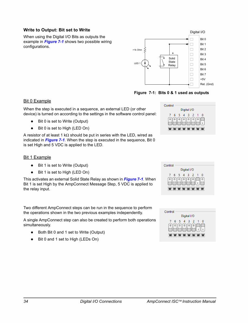
Write to Output: Bit set to WriteWhen using the Digital I/O Bits as outputs the example in Figure 7-1 shows two possible wiring configurations.
Bit 0 Example
When the step is executed in a sequence, an external LED (or other device) is turned on according to the settings in the software control panel:
Bit 0 is set to Write (Output)
Bit 0 is set to High (LED On)
A resistor of at least 1 kΩ should be put in series with the LED, wired as indicated in Figure 7-1. When the step is executed in the sequence, Bit 0 is set High and 5 VDC is applied to the LED.
Bit 1 Example
Bit 1 is set to Write (Output)
Bit 1 is set to High (LED On)
This activates an external Solid State Relay as shown in Figure 7-1. When Bit 1 is set High by the AmpConnect Message Step, 5 VDC is applied to the relay input.
Two different AmpConnect steps can be run in the sequence to perform the operations shown in the two previous examples independently.
A single AmpConnect step can also be created to perform both operations simultaneously.
Both Bit 0 and 1 set to Write (Output)
Bit 0 and 1 set to High (LEDs On)
Digital I/O
>1k Ohm
Bit 0
Bit 1
Bit 2
Bit 3
Bit 4
Bit 5
Bit 6
Bit 7
+5V
Ret. (Gnd)
LED 1
+SolidStateRelay
Figure 7-1: Bits 0 & 1 used as outputs
34 Digital I/O Connections AmpConnect ISCTM Instruction Manual
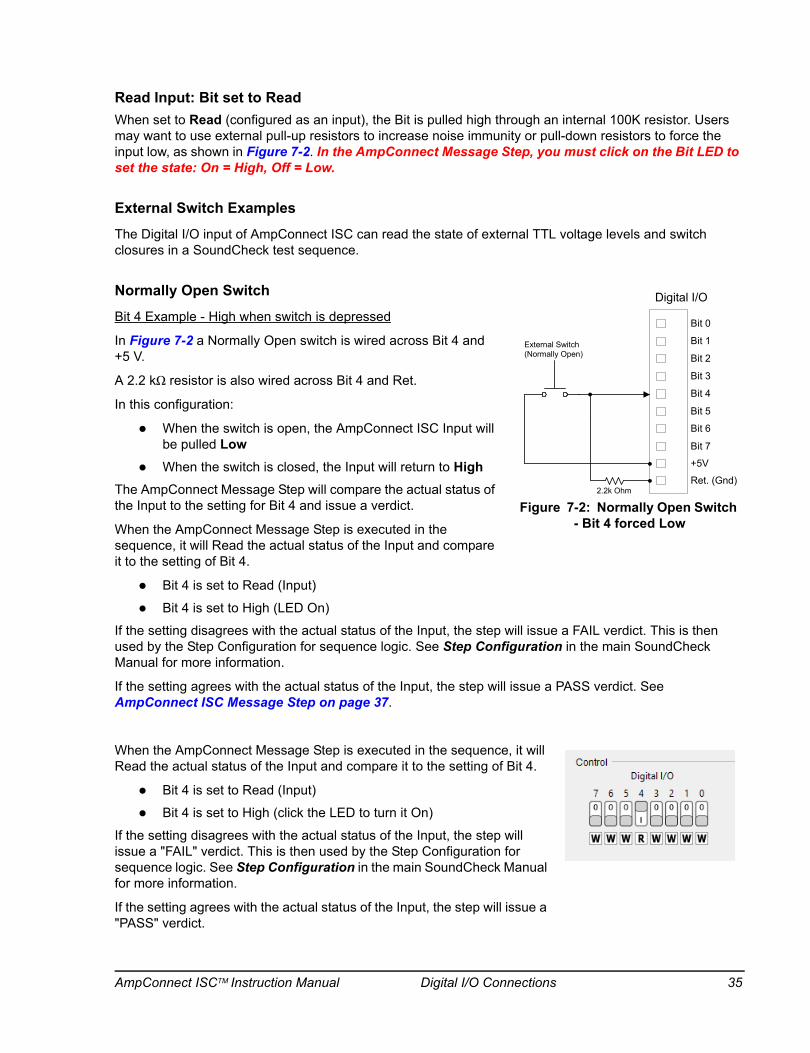
Read Input: Bit set to ReadWhen set to Read (configured as an input), the Bit is pulled high through an internal 100K resistor. Users may want to use external pull-up resistors to increase noise immunity or pull-down resistors to force the input low, as shown in Figure 7-2. In the AmpConnect Message Step, you must click on the Bit LED to set the state: On = High, Off = Low.
External Switch Examples
The Digital I/O input of AmpConnect ISC can read the state of external TTL voltage levels and switch closures in a SoundCheck test sequence.
Normally Open Switch
Bit 4 Example - High when switch is depressed
In Figure 7-2 a Normally Open switch is wired across Bit 4 and +5 V.
A 2.2 kΩ resistor is also wired across Bit 4 and Ret.
In this configuration:
When the switch is open, the AmpConnect ISC Input will be pulled Low
When the switch is closed, the Input will return to HighThe AmpConnect Message Step will compare the actual status of the Input to the setting for Bit 4 and issue a verdict.
When the AmpConnect Message Step is executed in the sequence, it will Read the actual status of the Input and compare it to the setting of Bit 4.
Bit 4 is set to Read (Input)
Bit 4 is set to High (LED On)
If the setting disagrees with the actual status of the Input, the step will issue a FAIL verdict. This is then used by the Step Configuration for sequence logic. See Step Configuration in the main SoundCheck Manual for more information.
If the setting agrees with the actual status of the Input, the step will issue a PASS verdict. See AmpConnect ISC Message Step on page 37.
When the AmpConnect Message Step is executed in the sequence, it will Read the actual status of the Input and compare it to the setting of Bit 4.
Bit 4 is set to Read (Input)
Bit 4 is set to High (click the LED to turn it On)
If the setting disagrees with the actual status of the Input, the step will issue a "FAIL" verdict. This is then used by the Step Configuration for sequence logic. See Step Configuration in the main SoundCheck Manual for more information.
If the setting agrees with the actual status of the Input, the step will issue a "PASS" verdict.
Digital I/O
Bit 0
Bit 1
Bit 2
Bit 3
Bit 4
Bit 5
Bit 6
Bit 7
+5V
Ret. (Gnd)2.2k Ohm
External Switch(Normally Open)
Figure 7-2: Normally Open Switch - Bit 4 forced Low
AmpConnect ISCTM Instruction Manual Digital I/O Connections 35
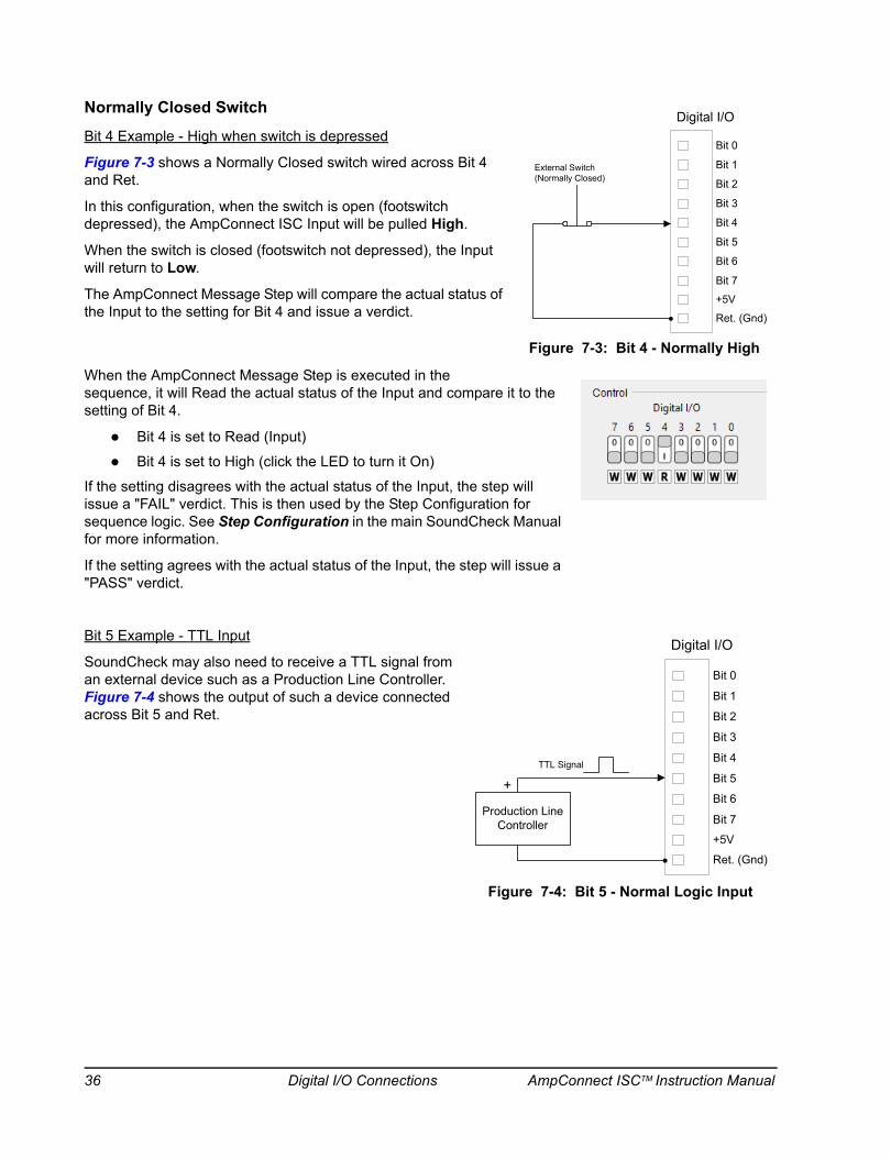
Normally Closed Switch
Bit 4 Example - High when switch is depressed
Figure 7-3 shows a Normally Closed switch wired across Bit 4 and Ret.
In this configuration, when the switch is open (footswitch depressed), the AmpConnect ISC Input will be pulled High.
When the switch is closed (footswitch not depressed), the Input will return to Low.
The AmpConnect Message Step will compare the actual status of the Input to the setting for Bit 4 and issue a verdict.
When the AmpConnect Message Step is executed in the sequence, it will Read the actual status of the Input and compare it to the setting of Bit 4.
Bit 4 is set to Read (Input)
Bit 4 is set to High (click the LED to turn it On)
If the setting disagrees with the actual status of the Input, the step will issue a "FAIL" verdict. This is then used by the Step Configuration for sequence logic. See Step Configuration in the main SoundCheck Manual for more information.
If the setting agrees with the actual status of the Input, the step will issue a "PASS" verdict.
Bit 5 Example - TTL Input
SoundCheck may also need to receive a TTL signal from an external device such as a Production Line Controller. Figure 7-4 shows the output of such a device connected across Bit 5 and Ret.
Digital I/O
Bit 0
Bit 1
Bit 2
Bit 3
Bit 4
Bit 5
Bit 6
Bit 7
+5V
Ret. (Gnd)
External Switch(Normally Closed)
Figure 7-3: Bit 4 - Normally High
Digital I/O
Bit 0
Bit 1
Bit 2
Bit 3
Bit 4
Bit 5
Bit 6
Bit 7
+5V
Ret. (Gnd)
+TTL Signal
Production LineController
Figure 7-4: Bit 5 - Normal Logic Input
36 Digital I/O Connections AmpConnect ISCTM Instruction Manual
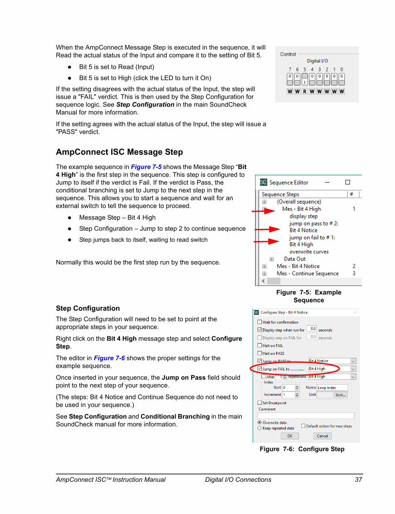
When the AmpConnect Message Step is executed in the sequence, it will Read the actual status of the Input and compare it to the setting of Bit 5.
Bit 5 is set to Read (Input)
Bit 5 is set to High (click the LED to turn it On)
If the setting disagrees with the actual status of the Input, the step will issue a "FAIL" verdict. This is then used by the Step Configuration for sequence logic. See Step Configuration in the main SoundCheck Manual for more information.
If the setting agrees with the actual status of the Input, the step will issue a "PASS" verdict.
AmpConnect ISC Message StepThe example sequence in Figure 7-5 shows the Message Step “Bit 4 High” is the first step in the sequence. This step is configured to Jump to itself if the verdict is Fail. If the verdict is Pass, the conditional branching is set to Jump to the next step in the sequence. This allows you to start a sequence and wait for an external switch to tell the sequence to proceed.
Message Step – Bit 4 High
Step Configuration – Jump to step 2 to continue sequence
Step jumps back to itself, waiting to read switch
Normally this would be the first step run by the sequence.
Step ConfigurationThe Step Configuration will need to be set to point at the appropriate steps in your sequence.
Right click on the Bit 4 High message step and select Configure Step.
The editor in Figure 7-6 shows the proper settings for the example sequence.
Once inserted in your sequence, the Jump on Pass field should point to the next step of your sequence.
(The steps: Bit 4 Notice and Continue Sequence do not need to be used in your sequence.)
See Step Configuration and Conditional Branching in the main SoundCheck manual for more information.
Figure 7-5: Example Sequence
Figure 7-6: Configure Step
AmpConnect ISCTM Instruction Manual Digital I/O Connections 37
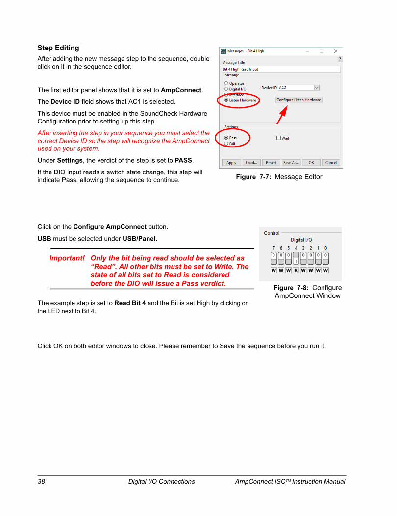
Step EditingAfter adding the new message step to the sequence, double click on it in the sequence editor.
The first editor panel shows that it is set to AmpConnect.
The Device ID field shows that AC1 is selected.
This device must be enabled in the SoundCheck Hardware Configuration prior to setting up this step.
After inserting the step in your sequence you must select the correct Device ID so the step will recognize the AmpConnect used on your system.
Under Settings, the verdict of the step is set to PASS.
If the DIO input reads a switch state change, this step will indicate Pass, allowing the sequence to continue.
Click on the Configure AmpConnect button.
USB must be selected under USB/Panel.
Important! Only the bit being read should be selected as “Read”. All other bits must be set to Write. The state of all bits set to Read is considered before the DIO will issue a Pass verdict.
The example step is set to Read Bit 4 and the Bit is set High by clicking on the LED next to Bit 4.
Click OK on both editor windows to close. Please remember to Save the sequence before you run it.
Figure 7-7: Message Editor
Figure 7-8: Configure AmpConnect Window
38 Digital I/O Connections AmpConnect ISCTM Instruction Manual
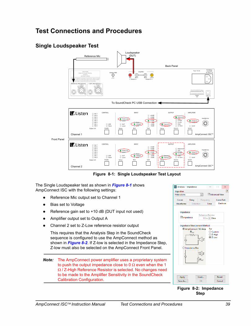
Test Connections and Procedures
Single Loudspeaker Test
The Single Loudspeaker test as shown in Figure 8-1 shows AmpConnect ISC with the following settings:
Reference Mic output set to Channel 1
Bias set to Voltage
Reference gain set to +10 dB (DUT input not used)
Amplifier output set to Output A
Channel 2 set to Z-Low reference resistor output
This requires that the Analysis Step in the SoundCheck sequence is configured to use the AmpConnect method as shown in Figure 8-2. If Z-low is selected in the Impedance Step, Z-low must also be selected on the AmpConnect Front Panel.
Note: The AmpConnect power amplifier uses a proprietary system to push the output impedance close to 0 Ω even when the 1 Ω / Z-High Reference Resistor is selected. No changes need to be made to the Amplifier Sensitivity in the SoundCheck Calibration Configuration.
INPUT
ReferenceLevel
DUTLevel
NoneVoltageIEPE
+40dB+30dB+20dB+10dB
0dB-10dB-20dB
Bias Gain Setup Source Select
Channel 1Channel 2
Output AOutput B
Level
CONTROL OUTPUT AMPLIFIER
SetupEnable
USBPanel
Digital I/O
Bit 6Bit 5Bit 4Bit 3Bit 2Bit 1Bit 0
Bit 7
Z-HighZ-LowAmp
ReferenceDUT
1V Sine
INPUT
ReferenceLevel
DUTLevel
NoneVoltageIEPE
+40dB+30dB+20dB+10dB
0dB-10dB-20dB
Bias Gain Setup Source Select
Channel 1Channel 2
Output AOutput B
Level
CONTROL OUTPUT AMPLIFIER
SetupEnable
USBPanel
Digital I/O
Bit 6Bit 5Bit 4Bit 3Bit 2Bit 1Bit 0
Bit 7
Z-HighZ-LowAmp
ReferenceDUT
1V Sine
CAUTIONRISK OF ELECTRICAL
SHOCKDO NOT OPEN
CAUTION: TO REDUCE THE RISK OF ELECTRICAL SHOCK, DO NOT REMOVE COVER. NO USER-SERVICABLE PARTS INSIDE. REFER
SERVICING TO QUALIFIED SERVICE PERSONNEL.
PUSH
Reference (Microphone) DUT (Microphone)
USB 2.0DigitalI/O
AC Rating:110-240V
50-60Hz, 2AFuse: T2.0A
Bit
0Bit
1Bit
2Bit
3Bit
4Bit
5Bit
6Bit
7+
5VRet
.
- Output B ++ Output A -
PUSH
Amplifier
Red Black Black Yellow
Chassis GND
Reference MicLoudspeaker
(DUT)
Channel 1
Channel 2
Back Panel
Front Panel
To SoundCheck PC USB Connection
AmpConnect ISC™
Headphone
AmpConnect ISC™
Headphone
Figure 8-1: Single Loudspeaker Test Layout
Figure 8-2: Impedance Step
AmpConnect ISCTM Instruction Manual Test Connections and Procedures 39

Two Loudspeaker Test
Figure 8-3 shows AmpConnect ISC setup to test two loudspeakers simultaneously. (This does not include impedance measurement.)
Reference Mic 1 output set to Channel 1
Bias set to Voltage
Reference gain set to +10 dB
DUT Mic (Reference Mic 2) output set to Channel 2
Bias set to Voltage
DUT gain set to +10 dB
Amplifier output set to Output A and B
Note: Connecting two loudspeakers in parallel to one amplifier output reduces the impedance of the load, e.g., 8 Ω in parallel with 8 Ω equals 4 Ω. When testing speaker loads between 3 and 4 Ω, one of the Output Channels must be set to Z-High so that the 1 Ω reference resistor will increase the load as seen by AmpConnect ISC. This will reduce the output power of AmpConnect ISC proportionately by the ratio of the reference resistor divided by the “loudspeaker plus reference resistor” impedance. Example: A 3 Ω loudspeaker with a 1 Ω reference resistor will reduce the power output by ¼ x 60 watts = 15 Watts, leaving 45 Watts available to drive the load. Also, because of AmpConnect ISC’s extra dissipated power internally, its upper operating temperature limit may be lowered.
Note: The AmpConnect power amplifier uses a proprietary system to push the output impedance close to 0 Ω even when the 1 Ω / Z-High Reference Resistor is selected. No changes need to be made to the Amplifier Sensitivity in the SoundCheck Calibration Configuration.
INPUT
ReferenceLevel
DUTLevel
NoneVoltageIEPE
+40dB+30dB+20dB+10dB
0dB-10dB-20dB
Bias Gain Setup Source Select
Channel 1Channel 2
Output AOutput B
Level
CONTROL OUTPUT AMPLIFIER
SetupEnable
USBPanel
Digital I/O
Bit 6Bit 5Bit 4Bit 3Bit 2Bit 1Bit 0
Bit 7
Z-HighZ-LowAmp
ReferenceDUT
1V Sine
INPUT
ReferenceLevel
DUTLevel
NoneVoltageIEPE
+40dB+30dB+20dB+10dB
0dB-10dB-20dB
Bias Gain Setup Source Select
Channel 1Channel 2
Output AOutput B
Level
CONTROL OUTPUT AMPLIFIER
SetupEnable
USBPanel
Digital I/O
Bit 6Bit 5Bit 4Bit 3Bit 2Bit 1Bit 0
Bit 7
Z-HighZ-LowAmp
ReferenceDUT
1V Sine
CAUTIONRISK OF ELECTRICAL
SHOCKDO NOT OPEN
CAUTION: TO REDUCE THE RISK OF ELECTRICAL SHOCK, DO NOT REMOVE COVER. NO USER-SERVICABLE PARTS INSIDE. REFER
SERVICING TO QUALIFIED SERVICE PERSONNEL.
PUSH
Reference (Microphone) DUT (Microphone)
USB 2.0DigitalI/O
AC Rating:110-240V
50-60Hz, 2AFuse: T2.0A
Bit
0Bit
1Bit
2Bit
3Bit
4Bit
5Bit
6Bit
7+
5VRet
.
- Output B ++ Output A -
PUSH
Amplifier
Red Black Black Yellow
Chassis GND
Loudspeaker (DUT) 1
Loudspeaker (DUT) 2
Channel 1
Channel 2
Reference Mic 2
Reference Mic 1
Back Panel
Front Panel
To SoundCheck PC USB Connection
AmpConnect ISC™
Headphone
AmpConnect ISC™
Headphone
Figure 8-3: Two Loudspeaker Test Layout
40 Test Connections and Procedures AmpConnect ISCTM Instruction Manual
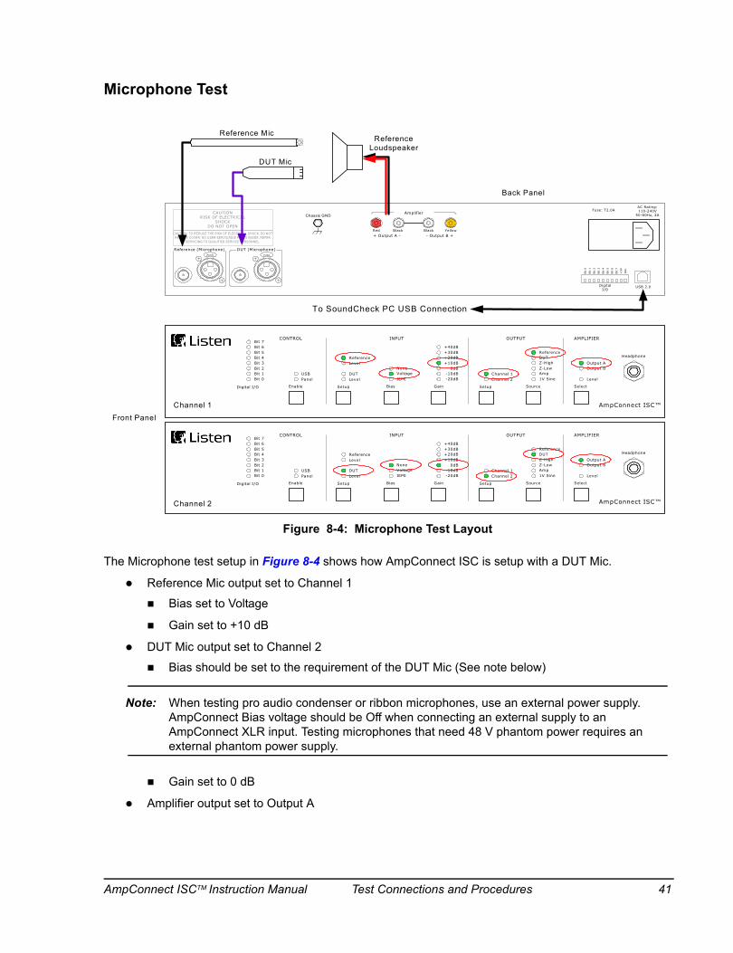
Microphone Test
The Microphone test setup in Figure 8-4 shows how AmpConnect ISC is setup with a DUT Mic.
Reference Mic output set to Channel 1
Bias set to Voltage
Gain set to +10 dB
DUT Mic output set to Channel 2
Bias should be set to the requirement of the DUT Mic (See note below)
Note: When testing pro audio condenser or ribbon microphones, use an external power supply. AmpConnect Bias voltage should be Off when connecting an external supply to an AmpConnect XLR input. Testing microphones that need 48 V phantom power requires an external phantom power supply.
Gain set to 0 dB
Amplifier output set to Output A
INPUT
ReferenceLevel
DUTLevel
NoneVoltageIEPE
+40dB+30dB+20dB+10dB
0dB-10dB-20dB
Bias Gain Setup Source Select
Channel 1Channel 2
Output AOutput B
Level
CONTROL OUTPUT AMPLIFIER
SetupEnable
USBPanel
Digital I/O
Bit 6Bit 5Bit 4Bit 3Bit 2Bit 1Bit 0
Bit 7
Z-HighZ-LowAmp
ReferenceDUT
1V Sine
INPUT
ReferenceLevel
DUTLevel
NoneVoltageIEPE
+40dB+30dB+20dB+10dB
0dB-10dB-20dB
Bias Gain Setup Source Select
Channel 1Channel 2
Output AOutput B
Level
CONTROL OUTPUT AMPLIFIER
SetupEnable
USBPanel
Digital I/O
Bit 6Bit 5Bit 4Bit 3Bit 2Bit 1Bit 0
Bit 7
Z-HighZ-LowAmp
ReferenceDUT
1V Sine
CAUTIONRISK OF ELECTRICAL
SHOCKDO NOT OPEN
CAUTION: TO REDUCE THE RISK OF ELECTRICAL SHOCK, DO NOT REMOVE COVER. NO USER-SERVICABLE PARTS INSIDE. REFER
SERVICING TO QUALIFIED SERVICE PERSONNEL.
PUSH
Reference (Microphone) DUT (Microphone)
USB 2.0DigitalI/O
AC Rating:110-240V
50-60Hz, 2AFuse: T2.0A
Bit
0
Bit
1
Bit
2
Bit
3
Bit
4
Bit
5
Bit
6
Bit
7
+5V
Ret
.
- Output B ++ Output A -
PUSH
Amplifier
Red Black Black Yellow
Chassis GND
Reference Loudspeaker
Channel 1
Channel 2
Reference Mic
Back Panel
Front Panel
AmpConnect ISC™
Headphone
AmpConnect ISC™
Headphone
DUT Mic
To SoundCheck PC USB Connection
Figure 8-4: Microphone Test Layout
AmpConnect ISCTM Instruction Manual Test Connections and Procedures 41
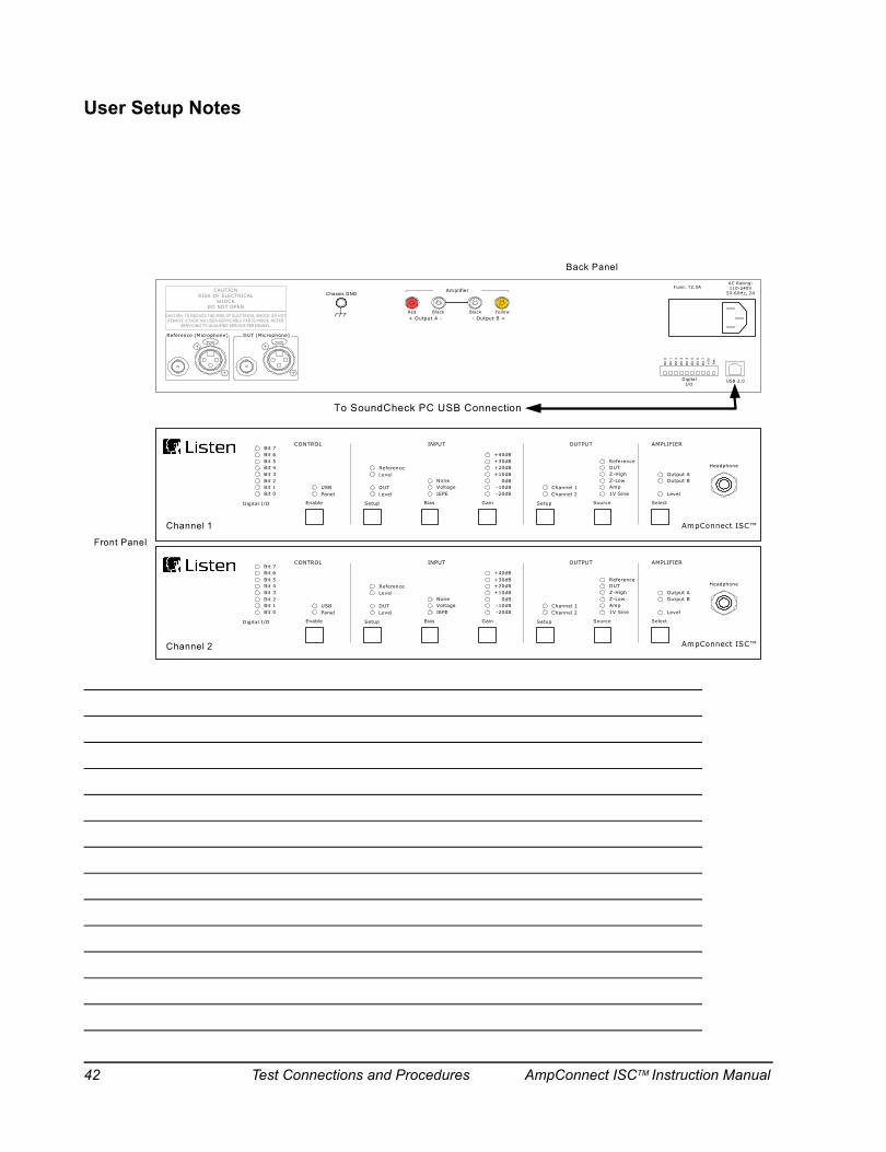
User Setup Notes
INPUT
ReferenceLevel
DUTLevel
NoneVoltageIEPE
+40dB+30dB+20dB+10dB
0dB-10dB-20dB
Bias Gain Setup Source Select
Channel 1Channel 2
Output AOutput B
Level
CONTROL OUTPUT AMPLIFIER
SetupEnable
USBPanel
Digital I/O
Bit 6Bit 5Bit 4Bit 3Bit 2Bit 1Bit 0
Bit 7
Z-HighZ-LowAmp
ReferenceDUT
1V Sine
INPUT
ReferenceLevel
DUTLevel
NoneVoltageIEPE
+40dB+30dB+20dB+10dB
0dB-10dB-20dB
Bias Gain Setup Source Select
Channel 1Channel 2
Output AOutput B
Level
CONTROL OUTPUT AMPLIFIER
SetupEnable
USBPanel
Digital I/O
Bit 6Bit 5Bit 4Bit 3Bit 2Bit 1Bit 0
Bit 7
Z-HighZ-LowAmp
ReferenceDUT
1V Sine
CAUTIONRISK OF ELECTRICAL
SHOCKDO NOT OPEN
CAUTION: TO REDUCE THE RISK OF ELECTRICAL SHOCK, DO NOT REMOVE COVER. NO USER-SERVICABLE PARTS INSIDE. REFER
SERVICING TO QUALIFIED SERVICE PERSONNEL.
PUSH
Reference (Microphone) DUT (Microphone)
USB 2.0DigitalI/O
AC Rating:110-240V
50-60Hz, 2AFuse: T2.0A
Bit
0
Bit
1
Bit
2
Bit
3
Bit
4
Bit
5
Bit
6
Bit
7
+5V
Ret
.
- Output B ++ Output A -
PUSH
Amplifier
Red Black Black Yellow
Chassis GND
Channel 1
Channel 2
Back Panel
Front Panel
To SoundCheck PC USB Connection
AmpConnect ISC™
Headphone
AmpConnect ISC™
Headphone
42 Test Connections and Procedures AmpConnect ISCTM Instruction Manual
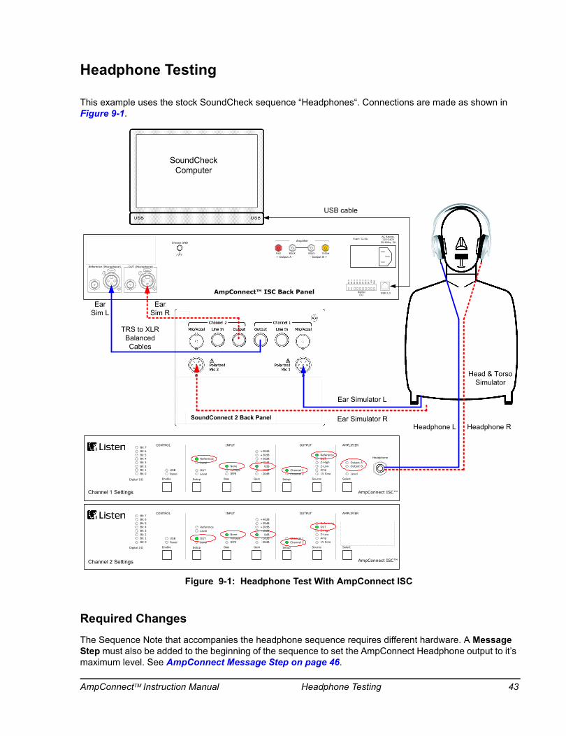
Headphone Testing
This example uses the stock SoundCheck sequence “Headphones“. Connections are made as shown in Figure 9-1.
Required ChangesThe Sequence Note that accompanies the headphone sequence requires different hardware. A Message Step must also be added to the beginning of the sequence to set the AmpConnect Headphone output to it’s maximum level. See AmpConnect Message Step on page 46.
PUSH
CAUTIONRISK OF ELECTRICAL
SHOCKDO NOT OPEN
CAUTION: TO REDUCE THE RISK OF ELECTRICAL SHOCK, DO NOT REMOVE COVER. NO USER-SERVICABLE PARTS INSIDE. REFER
SERVICING TO QUALIFIED SERVICE PERSONNEL.
Reference (Microphone) DUT (Microphone)
USB 2.0DigitalI/O
AC Rating:110-240V
50-60Hz, 2AFuse: T2.0A
Bit
0Bit
1Bit
2Bit
3Bit
4Bit
5Bit
6Bit
7+
5VR
et.
PUSH
Chassis GND
USB cable
- Output B ++ Output A -
Amplifier
Red Black Black Yellow
AmpConnect™ ISC Back Panel
INPUT
ReferenceLevel
DUTLevel
NoneVoltageIEPE
+40dB+30dB+20dB+10dB
0dB-10dB-20dB
Bias Gain Setup Source Select
Channel 1Channel 2
Output AOutput B
Level
CONTROL OUTPUT AMPLIFIER
SetupEnable
USBPanel
Digital I/O
Bit 6Bit 5Bit 4Bit 3Bit 2Bit 1Bit 0
Bit 7
Z-HighZ-LowAmp
ReferenceDUT
1V Sine
Channel 1 Settings AmpConnect ISC™
Headphone
INPUT
ReferenceLevel
DUTLevel
NoneVoltageIEPE
+40dB+30dB+20dB+10dB
0dB-10dB-20dB
Bias Gain Setup Source Select
Channel 1Channel 2
Output AOutput B
Level
CONTROL OUTPUT AMPLIFIER
SetupEnable
USBPanel
Digital I/O
Bit 6Bit 5Bit 4Bit 3Bit 2Bit 1Bit 0
Bit 7
Z-HighZ-LowAmp
ReferenceDUT
1V Sine
Channel 2 Settings AmpConnect ISC™
Headphone
Ear Simulator R
Ear Simulator L
Ear Sim R
Ear Sim L
Headphone RHeadphone L
Head & Torso Simulator
SoundConnect 2 Back Panel
TRS to XLR Balanced Cables
SoundCheckComputer
Figure 9-1: Headphone Test With AmpConnect ISC
AmpConnectTM Instruction Manual Headphone Testing 43
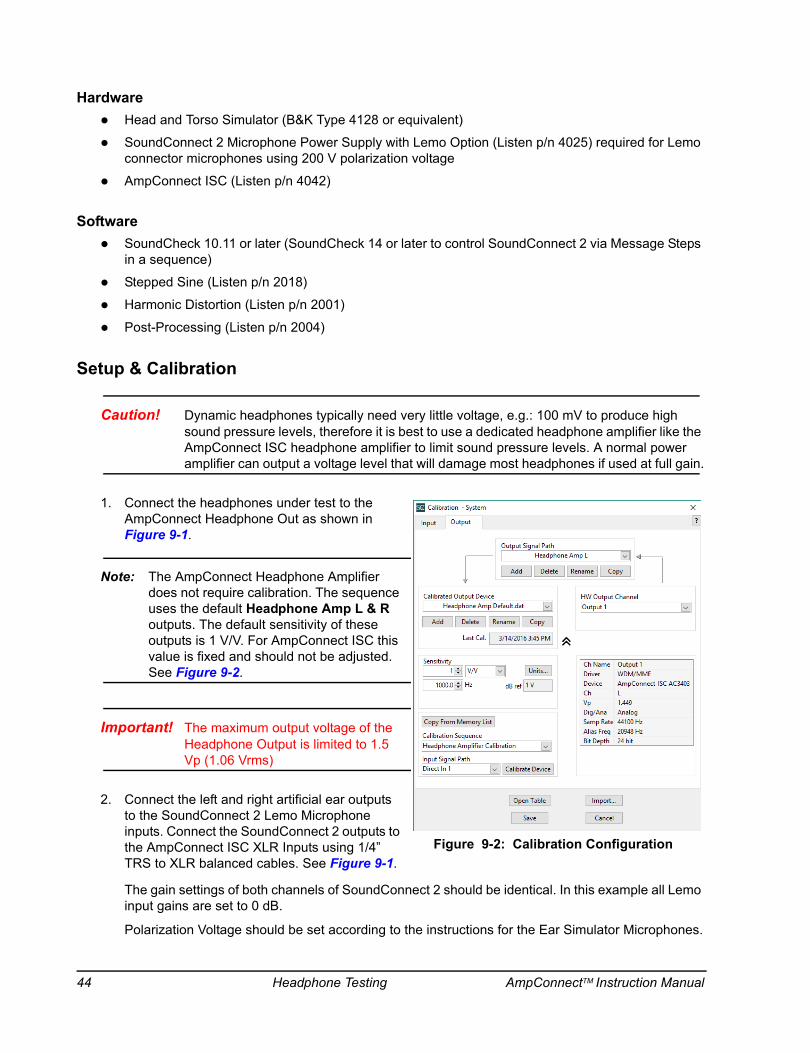
HardwareHead and Torso Simulator (B&K Type 4128 or equivalent)
SoundConnect 2 Microphone Power Supply with Lemo Option (Listen p/n 4025) required for Lemo connector microphones using 200 V polarization voltage
AmpConnect ISC (Listen p/n 4042)
SoftwareSoundCheck 10.11 or later (SoundCheck 14 or later to control SoundConnect 2 via Message Steps in a sequence)
Stepped Sine (Listen p/n 2018)
Harmonic Distortion (Listen p/n 2001)
Post-Processing (Listen p/n 2004)
Setup & Calibration
Caution! Dynamic headphones typically need very little voltage, e.g.: 100 mV to produce high sound pressure levels, therefore it is best to use a dedicated headphone amplifier like the AmpConnect ISC headphone amplifier to limit sound pressure levels. A normal power amplifier can output a voltage level that will damage most headphones if used at full gain.
1. Connect the headphones under test to the AmpConnect Headphone Out as shown in Figure 9-1.
Note: The AmpConnect Headphone Amplifier does not require calibration. The sequence uses the default Headphone Amp L & R outputs. The default sensitivity of these outputs is 1 V/V. For AmpConnect ISC this value is fixed and should not be adjusted. See Figure 9-2.
Important! The maximum output voltage of the Headphone Output is limited to 1.5 Vp (1.06 Vrms)
2. Connect the left and right artificial ear outputs to the SoundConnect 2 Lemo Microphone inputs. Connect the SoundConnect 2 outputs to the AmpConnect ISC XLR Inputs using 1/4” TRS to XLR balanced cables. See Figure 9-1.
The gain settings of both channels of SoundConnect 2 should be identical. In this example all Lemo input gains are set to 0 dB.
Polarization Voltage should be set according to the instructions for the Ear Simulator Microphones.
Figure 9-2: Calibration Configuration
44 Headphone Testing AmpConnectTM Instruction Manual

3. The Head and Torso Simulator (HATS) has both left and right ear simulators which need to be calibrated before measuring the headphones. (Refer to the HATS manual for further instructions on mounting a microphone calibrator on the artificial ears.)
4. In the SoundCheck Microphone Calibration Editor, select B&K 4231 & UA 1546 ear adapter for calibrating the B&K 4128 HATS artificial ears (similar in sensitivity to the B&K 4134 pressure mic).
5. Use the manual Signal Generator and Multimeter to determine the appropriate test level that yields the desired headphone output SPL, e.g.:
Determine test voltage level for 100 dBSPL for measuring distortion
Set the Signal Generator to 1 kHz. Start at a low voltage, 20 mV, and increase until the Multimeter shows 100 dB SPL.
Use the level in the Signal Generator for the Test Level in the Sequence.
AmpConnect Front Panel Settings
Input SectionReference Input - Routed to Ear Sim L - according to the SoundCheck default Calibration Configuration
Dut Input - Routed to Ear Sim R - according to the SoundCheck default Calibration Configuration
Both Reference and DUT channels set to 0 dB gain
Bias is off for both channels
Output SectionChannel 1 set to Reference
Channel 2 set to DUT
Amplifier SectionPower amp A & B outputs set to Off
Important! Impedance testing is only available when connecting to the AmpConnect main power amplifier binding posts. Since this is a mono power amplifier, all headphone measurements can only be done on one channel at a time.
Note: Headphones with impedances greater than 50 Ω may need to be tested using the AmpConnect power amp output. Refer to AmpConnect ISC Specifications on page 53.
WARNING! When monitoring AmpConnect signals with headphones, REMOVE HEADPHONES before making any changes to AmpConnect settings or SoundCheck settings. This is to prevent hearing damage due to high sound pressure levels.
AmpConnectTM Instruction Manual Headphone Testing 45

AmpConnect Message StepAmpConnect ISC can be controlled with a Message Step in the SoundCheck test sequence. The example in Figure 9-3 shows the settings used in this example. This is the first step in the sequence.
All controls are the same as the front panel controls noted in AmpConnect Front Panel Settings on page 45, with the addition of the Headphone Monitor Control. This function is only available in the SoundCheck Message Step. See Headphone Settings on page 30.
Inserting this step turns off the 27 dB output pad on the Headphone Output (AmpConnect default)
The Headphone Output will return to the default 27 dB attenuation when AmpConnect is turned off.
Select SoundCheck Output in order to send the SoundCheck Stimulus to the headphones
Gain is greyed out since this is set in the Calibration Configuration
Figure 9-3: Message Step Settings
46 Headphone Testing AmpConnectTM Instruction Manual
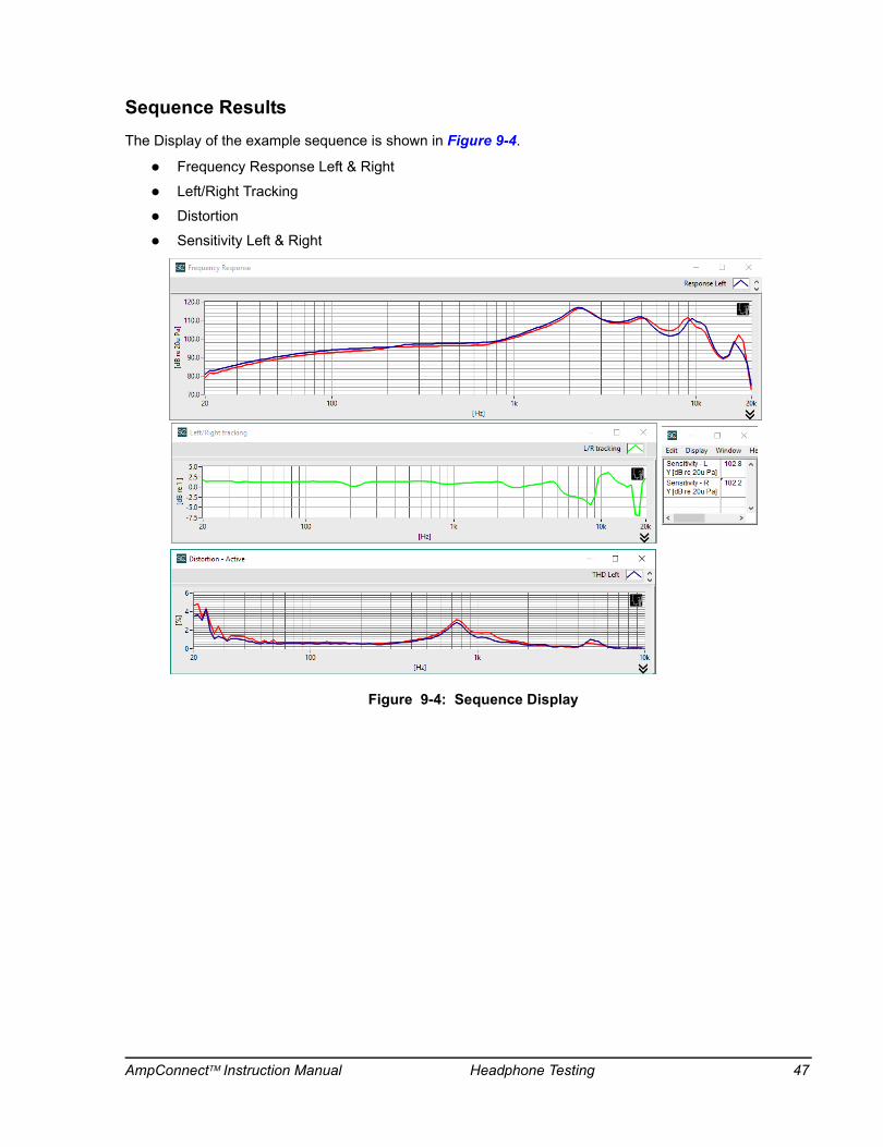
Sequence ResultsThe Display of the example sequence is shown in Figure 9-4.
Frequency Response Left & Right
Left/Right Tracking
Distortion
Sensitivity Left & Right
Figure 9-4: Sequence Display
AmpConnectTM Instruction Manual Headphone Testing 47

page intentionally left blank
AmpConnectTM Instruction Manual Headphone Testing 48
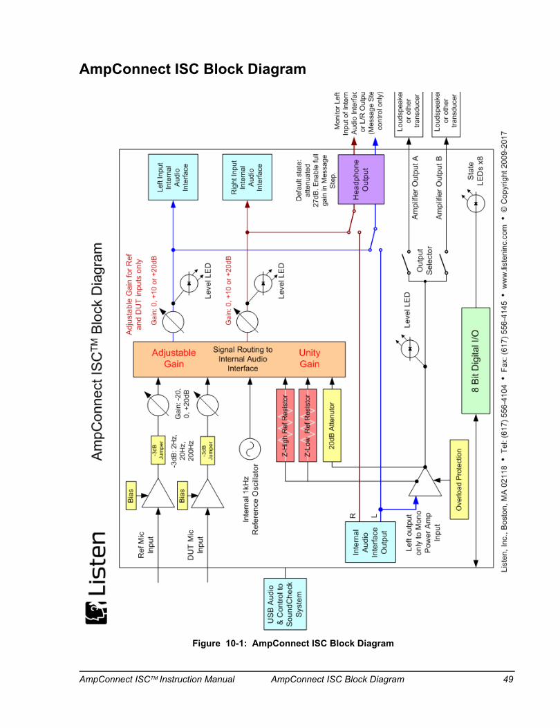
AmpConnect ISC Block Diagram
Figure 10-1: AmpConnect ISC Block Diagram
AmpConnect ISCTM Instruction Manual AmpConnect ISC Block Diagram 49

Block Diagram ExplanationsSignal routing controlled from AmpConnect ISC front panel or from SoundCheck Message Step.
Ref and DUT Input signals routed to Internal Audio Interface inputs
Adjustable Gain after routing for Ref and DUT inputs only
Internal 1 kHz Reference Oscillator can be routed to Internal Audio Interface inputs
Internal Audio Interface L + R outputs can be routed to stereo Headphone output
Power Up default state: Headphone Output is attenuated by 27 dB. You must use a Message Step in SoundCheck to enable full gain on the Headphone Output. See AmpConnect Message Step on page 46.
The Headphone Output will return to the default 27 dB attenuation when AmpConnect is turned off.
Only the Left channel of Internal Audio Interface Output is routed to input of mono power amplifier
Power amp outputs can be routed to Outputs A, B or A + B
Power amp can be internally routed through 20 dB attenuator, to internal audio interface inputs for calibration or monitoring
All signals that can be routed to Internal Audio Interface inputs can also be routed to stereo Headphone output for signal monitoring
Ref Mic Input
DUT Mic Input
Internal 1kHz Reference Oscillator
Right Input Internal Audio
Interface
Gain: -20, 0, +20dB
Gain: 0, +10 or +20dB
Gain: 0, +10 or +20dB
Bias
Level LED
Level LED
Bias-3dB: 2Hz,
20Hz, 200Hz
Left Input Internal Audio
Interface
Signal R
outing toInternal A
udio Interface
Adjustable Gain for Ref and DUT inputs only
-3dBJumper
-3dBJumper
Z High Ref Resistor
Adjustable G
ain
Monitor Left Input of Internal Audio Interface or L/R Output
(Message Step control only)
Headphone Output
Internal Audio
Interface Output
20dB Attenutor
R
L
Step.
Left output only to MonoPower Amp
Input
O l d P t ti
Internal Audio
Interface Output
R
L
Left output only to MonoPower Amp
Input
Amplifier Output A
Amplifier Output B
Loudspeaker or other
transducer
Loudspeaker or other
transducerOverload Protection
Level LEDOutput
Selector
Left output only to MonoPower Amp
Input
Le
Internal Audio
Interface Output
ty n
20dB Attenutor
R
L
50 AmpConnect ISC Block Diagram AmpConnect ISCTM Instruction Manual

Internal Jumper Settings
Important! Only the noted jumpers and potentiometers should be adjusted. Other internal settings should not be changed! These are set at the factory and should only be changed with instruction from Listen, Inc.
Bias Voltage
The Bias Voltage of the Reference and DUT Inputs can be adjusted. See Figure 10-2.
R188 - Reference Bias Potentiometer
R157 - DUT Bias Potentiometer
Default: 10 VDC
Range: 500 mV to 12 VDC
Measure voltage across BNC connector or Pins 2 and 3 of XLR connector
IEPE Voltage is not adjustable
Balanced vs Single Ended Jumper Settings
The XLR inputs function as Balanced Inputs.
Adding the jumper across pins 2 & 3 of J20 and J28 will set the XLR inputs to Single Ended.
The jumper connects pin 3 (-) to pin 1 (Gnd) on the XLR connectors.
AmpConnect ISC ships with J20 & J28 jumpers OFF by default.
Open the AmpConnect case if you need to verify the current jumper settings.
The wiring diagram for the connectors is shown in Figure 5-2 on page 23.
3 dB Down Point
The 3 dB Down Point (Low Frequency Roll-Off) of the Reference (J30) and DUT (J24) Inputs can be set using Jumpers on the PC board. See Figure 10-2.
As of SN1536, the default jumper position is 2 Hz: Jumper removed.
2 Hz - No Jumper. (default position) Recommended when using the BNC input(s) for electronic input signals.
20 Hz - Jumper across pins 1 and 2, 1st order (6 dB per octave)
200 Hz - Jumper across pins 2 and 3, 1st order (6 dB per octave)
123
123
Reference InputXLR
DUTInputXLR
R157 DUT/V
R188 REF/V
J30 REF
J24 DUT
Back of AmpConnect
Right side of PC board
123 123
J28 REF
J20 DUT
DUTBNC
REFBNC
Figure 10-2: Internal Adjustments
AmpConnect ISCTM Instruction Manual AmpConnect ISC Block Diagram 51

page intentionally left blank
52 AmpConnect ISC Block Diagram AmpConnect ISCTM Instruction Manual
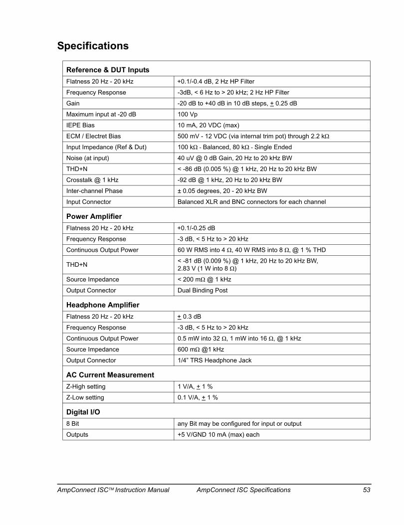
Specifications
Reference & DUT InputsFlatness 20 Hz - 20 kHz +0.1/-0.4 dB, 2 Hz HP Filter
Frequency Response -3dB, < 6 Hz to > 20 kHz; 2 Hz HP Filter
Gain -20 dB to +40 dB in 10 dB steps, + 0.25 dB
Maximum input at -20 dB 100 Vp
IEPE Bias 10 mA, 20 VDC (max)
ECM / Electret Bias 500 mV - 12 VDC (via internal trim pot) through 2.2 kΩ
Input Impedance (Ref & Dut) 100 kΩ - Balanced, 80 kΩ - Single Ended
Noise (at input) 40 uV @ 0 dB Gain, 20 Hz to 20 kHz BW
THD+N < -86 dB (0.005 %) @ 1 kHz, 20 Hz to 20 kHz BW
Crosstalk @ 1 kHz -92 dB @ 1 kHz, 20 Hz to 20 kHz BW
Inter-channel Phase ± 0.05 degrees, 20 - 20 kHz BW
Input Connector Balanced XLR and BNC connectors for each channel
Power AmplifierFlatness 20 Hz - 20 kHz +0.1/-0.25 dB
Frequency Response -3 dB, < 5 Hz to > 20 kHz
Continuous Output Power 60 W RMS into 4 Ω, 40 W RMS into 8 Ω, @ 1 % THD
THD+N < -81 dB (0.009 %) @ 1 kHz, 20 Hz to 20 kHz BW, 2.83 V (1 W into 8 Ω)
Source Impedance < 200 mΩ @ 1 kHz
Output Connector Dual Binding Post
Headphone AmplifierFlatness 20 Hz - 20 kHz + 0.3 dB
Frequency Response -3 dB, < 5 Hz to > 20 kHz
Continuous Output Power 0.5 mW into 32 Ω, 1 mW into 16 Ω, @ 1 kHz
Source Impedance 600 mΩ @1 kHz
Output Connector 1/4” TRS Headphone Jack
AC Current MeasurementZ-High setting 1 V/A, + 1 %
Z-Low setting 0.1 V/A, + 1 %
Digital I/O8 Bit any Bit may be configured for input or output
Outputs +5 V/GND 10 mA (max) each
AmpConnect ISCTM Instruction Manual AmpConnect ISC Specifications 53
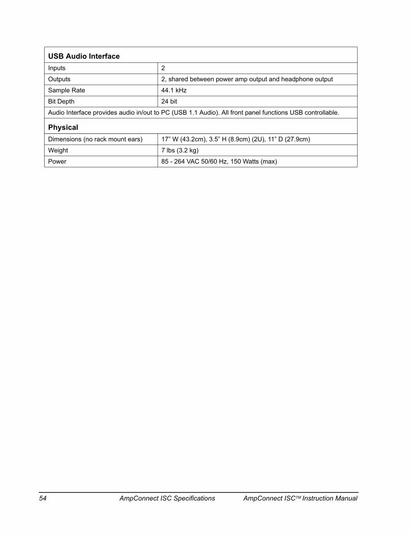
USB Audio InterfaceInputs 2
Outputs 2, shared between power amp output and headphone output
Sample Rate 44.1 kHz
Bit Depth 24 bit
Audio Interface provides audio in/out to PC (USB 1.1 Audio). All front panel functions USB controllable.
PhysicalDimensions (no rack mount ears) 17” W (43.2cm), 3.5” H (8.9cm) (2U), 11” D (27.9cm)
Weight 7 lbs (3.2 kg)
Power 85 - 264 VAC 50/60 Hz, 150 Watts (max)
54 AmpConnect ISC Specifications AmpConnect ISCTM Instruction Manual

INDEX
AAmpConnect ...................................................................27AmpConnect ISC Message Step ...................................37AmpConnect ISC Test Setup ...........................................3AmpConnect Setup in Windows XP ................................9Amplifier Calibration .......................................................13Audio Devices - Windows 7 .............................................7Audio Devices - Windows XP ..........................................7
BBias ..................................................................................19Bit set to Read ................................................................35Bit set to Write .................................................................34Block Diagram .................................................................49Blue Field ........................................................................26
CCalibration .......................................................................15Calibration Sequence .....................................................15Control .......................................................................17, 29Custom Step ....................................................................25
DdB level ............................................................................15Digital I/O ...................................................... 18, 24, 29, 33Digital I/O General rules .................................................33DUT (Microphone) Input ...........................................20, 24
EExternal Switch ...............................................................35
FFront Panel control .........................................................17
HHardware Configuration .................................................10Headphone Amplifier ......................................................15Headphone Output .........................................................17Headphone Output Pad ..................................... 17, 30, 46Headphone Testing .........................................................43
IIEPE .................................................................................19Import ..............................................................................10Input Monitor ...................................................................30Internal Jumper Settings ................................................51
LLevel ................................................................................15
MMessage Step ........................................ 25, 26, 37, 43, 46Microphone Calibration ..................................................15Microphone manufacturer’s specifications ....................15Monitor Control ...............................................................46
NNET framework .................................................................6
PPanel Control ..................................................................18
QQuiet ................................................................................20
RReading External Switch Closures ................................33Reference (Microphone) Input .................................20, 23Requirements ....................................................................5
SSelf Test Sequence .........................................................12Sequence-specific ..........................................................26Sound pressure level ......................................................15Specifications ..................................................................15System Calibration .......................................................... 11System Hardware .............................................................9
TTest ....................................................................................3Test Connections and Procedures ................................39Toggle Inputs ...................................................................30Toggle Outputs ................................................................30TTL Input .........................................................................36
UUSB Control ....................................................................18USB Panel control ..........................................................17
ZZ-High ..............................................................................20Z-Low ...............................................................................20
AmpConnect ISCTM Instruction Manual INDEX 55

page intentionally left blank
56 INDEX AmpConnect ISCTM Instruction Manual
AmpConnect ISCTM Instruction Manual 57
Rev 052417
Contact Information
Contact the Listen office at 617-556-4104, Monday thru Friday, between 9 AM and 5 PM EST.
or email:
Sales - [email protected]
Technical Support - [email protected]
Listen Website: www.listeninc.com/
© Listen, Inc 2009 - 2017. All rights reserved.
SoundCheck®, HarmonicTrak™, STWEEP™, SoundCheck ONE™, SoundMap™, NoiseCheck™, SoundConnect™, DC Connect™, AmpConnect™, AmpConnect ISC™, SC Amp™, SoundConnect 2™, AudioConnect™ and AudioConnect 4x4™ are trademarks of Listen, Inc.
® Microsoft, Windows, Windows NT and Active X are registered trademarks of Microsoft Corporation. Pentium is a registered trademark of Intel Corporation. Test Stand and LabVIEW are trademarks of National Instruments Corporation. Oracle is a registered trademark of Oracle Corporation. ICP is a registered trademark of PCB Group. Bluetooth is a registered trademark of Bluetooth SIG.