amphenol - jrh electronics ®amphenol ®/pyle connectors ... when wires are passed through the rigid...
TRANSCRIPT

Amphenol


Contents Star-Line®SeriesOverview..........................................................................................2
Star-LineEX®SeriesOverview....................................................................................3
EnvironmentalHighlights,DoubleLeadAcmeThreadFeatures, WireLimitationGuide...................................................................................................4
ContactInsertFeatures-ModI,ModII........................................................................5
ConnectorComponentOrderingDetails................................................................ 6-9
PlugHardwareAssemblies................................................................................ 10-13
ReceptacleHardwareAssemblies..................................................................... 14-22
StarlineEX®ProductInstructions....................................................................... 23-24
StarlineEX®OrderingDetails,EExdCableTypes............................................ 25-27
StarlineEX®Hardware...................................................................................... 28-30
StarlineEX®DescriptionofEquipment&PartNumberCodeLogic..........................31
StarlineEX®AssemblyandTerminationInstructions......................................... 32-40
SinglePolePowerConnectors.......................................................................... 41-45
InsertConfigurationListing,ElectricalRatings................................................... 46-47
SpareReplacementContactsforMODIIInserts.......................................................48
TerminationData........................................................................................................49
ThermocoupleContacts.............................................................................................50
InsertConfigurationIndex.................................................................................. 51-53
InsertConfigurations.......................................................................................... 54-81
V.F.D.InsertConfigurations................................................................................ 82-83
ConnectorComponents,SpareParts,CableAdaptersandAccessories.......... 84-89
ProtectionCoversandCapsAccessories.......................................................... 90-91
ConduitSystemAccessories.............................................................................. 92-93
Crimping,InsertionandRemovalTools............................................................. 94-95
ConnectorAssemblyandTerminationInstructions....................................................96
ConnectorswithRADSOK®HighAmperageContactsand OtherAmphenol®/Pyle®Connectors................................................................... 97-99
SalesOfficesandDistributorsListing......................................................................100
Cataloginformationforreferenceonly.Formoreassistance,contactyourlocalAmphenolfieldsalesofficeor:
AmphenolIndustrialOperations40-60DelawareAvenue,Sidney,NY13838-1395Phone:1-888-364-9011Fax:1-520-397-7169Technicalemail:[email protected]
ThiscatalogandmostallAmphenolcatalogsareavailableforviewing,printinganddownloadingonwebsites:www.amphenol-industrial.comwww.amphenol-aerospace.com


TheStar-LineEXSeriesisahybridformoftheparentStarline productline.TheseriesiscertifiedforuseinaZone1-IIchaz ardousenvironment.Classifiedfacilitiessuchaspetrochemical refineries,landandoffshoredrillingsystemsarebutafewof theapplicationsforthisbroadproductseries.• ATEXCERTIfIED–forZone1-IIchazardousenvironment.For
certificatecontactfactory• IECExCERTIfIED–
Forcertificatecontactfactory• CENELECIP68-8RATED–
ListedunderEExdIIcT6.PlugsandreceptacleslistedunderEExdeIIcT6.
• HARDANODICCOATING–Allmachinedaluminumparts finishedwithahard,scratch-resistantcoatingperMIL-A-8625,
TypeIII.Dielectricstrength1800volts.Heatresistanceof750°F.• SOLDER,CRIMPANDPRESSURETERMINALSAVAILABLE• REVERSIBLEINSERTS–Afullrangeofcontactinsertsforpower,signalandmixedapplicationsareavailable.All
areinterchangeableandreversibletosuitspecificneeds.• EASILYACCESSIBLEWIRETERMINALS–Conductorsarereadilyterminatedtocontacts.Cablehousingsare
slippedoverconductorsorleadsafterterminating.Cumbersomehandlingandseatingofinsertswithconductorsattachediseliminated.
• LARGEWIRINGSPACE–Amplewiringspaceisprovidedincablehousingsandhardware.
• HIGHTENSILESTRENGTHALUMINUM–BarStockComponentsprecisionmachined.Pointsofimpactdesignedforextrastrength.
• CABLEOPTIONS–StarlineEXSeriescanbeterminatedontounarmoredorarmoredandsheathedcablesbuilttoIEEE-45/UL1309,IEC,BS,DINandJICstandards.FlexiblecableslikeSOOW-A,W,G-GCandDLOconstructionscanalsobeusedwiththisSeries.
• EXCABLEGLANDS–WidevarietyofglandsareavailableforStar-LineEXconnectors.FormoreinformationaskfornewAmphenolCableGlandsandCordGripscatalog12-055.
• INSERTVARIETY–Abroadrangeofinsertsareofferedrangingfromsingle-contactto143contacts.Highamperageupto1135ampsat1000V/ACorDC.Contactsarehighqualitycopperwithsilverplating.(Goldplatingavailableasanoption)Compositeinsertsforpower,controlandinstrumentationserviceavailable.For Amphenol Star-Line product insert de-rating information per the National Electric Code, please consult the Amphenol Industrial website, www.amphenol-industrial.com. Chart is located under LItErAtUrE tab.
• RADSOK®HIGHAMPERAGECONTACTS–SpecialarrangementsareavailablewithRADSOKhighamperagecontacts.StandardStar-lineEXinsertsarenotinterchangeablewithnewRADSOKcontactinsertarrangements.
• RoHSCOMPLIANTPRODUCTAVAILABLE–ConsultAmphenolIndustrialOperations
STAR-LINE®EXSeries
RoHS
Amphenol
EU / 2002 / 95 / EC
Star-Line EX Connector with EX gland (EX-13-3 style shown)
Star-Line EX Series connectors are certified for use in Zone 1-IIc hazardous environment
3

EnvironmentalHighlights
Thedouble-leadAcmethreadisamoderatetorquequick-couplingthreadwhichpermitscompletecouplinginapproximatelyoneturnofthecouplingnut.Inaddition,thereareactuallytwoparallelthreadshavingstartingpoints180degreesapart.Allofthisensuresthatplugsandreceptaclesarebeingmatedorunmatedaxially.Thethreadcontourmakesitself-cleaning.
MIL-5015 REqUIREMENTS CLASSESA,B,E STAR-LINE,STAR-LOKPROPERTY J&R CONNECTORS
TEMPERATURE -67°Fto225°F TemperatureClassesA,B,E, (-55°Cto107°C) JandRcanwithstand257°F continuously.Forshortduration high-temperaturelife, consultfactory.
PRESSURE Norequirement 300PSIexternal (coupledconnectors) 200PSIinternal (withpinandsocketinserts)
AIRLEAKAGE 1cubicinch/ ExceedsClassesE hourmaximum andRspecifications
HUMIDITYAND 11/2timesA.C. ExceedsClassesMOISTURE voltageratingafter EandR.RESISTANCE 14days. MIL-5015 Exposureto MeetsMIL-STD-202B, 95%relative Method106A humidityat160°F.
CORROSION 48Hours– Saltspray:300daysRESISTANCE Method1001 –Noexposureofbasemetal. MIL-STD-1344 Noexposureof basemetal.
CHEMICAL Norequirement Oil,mostacidsRESISTANCE andalkalis.
DUST Norequirement MeetsMIL-STD-202B,RESISTANCE Method110,ConditionB
SHOCK 50Gminimum Exceeds60G’sRESISTANCE Certaininsertsavailable to200G.
VIBRATION Method2005 ExceedsMethodII& MethodII MIL-STD-167-1(Ships). MIL-STD-1344
TESTPROBE Contactsize ExceedsMIL-5015ABUSE No.16andNo.18 onallcontacts No.18through4/0.
WhytheDouble-LeadAcmeThread?
Therearerestrictionstothemaximumdiameterofwireastheyrelatetotherearorwiresideoftheconnectorinsertasfollows.ModI.Whenwiresarepassedthroughtherigidbackinsulationforeaseofsoldering: Wiresize Maximumdiameter #4/0 .747” #1/0 .555” #4 .400” #8 .262” #10 .201” #12 .150” #16 .107” #18 .086”ModII&III #10 .248” #12 .193” #16 .130” #18 .110”
WireLimitationGuide
One parallel thread removed to show actual thread angle.
Standard double-lead Acme. two parallel threads.
STAR-LINE®
4

AmphenolINDUSTRIAL
PressurizingSleeve
Green
Contact Seal
InsertSeal
Shell SealAdapter Seal Adapter Washer
Red
Cable Adapter
Coupling Nut
Plug Barrel
Rigid Insulator
Double LeadAcme Thread
Resilient Insulator
Receptacle Barrel
Pressure Sleeve
PressurePad
Double Lead Acme Thread
Shell SealAdapter Seal Adapter
Washer
PressurePad
Cable Adapter
Coupling Nut
Plug Shell
Rigid Front Insulator
Resilient Contact Seal Laminant
Rigid Rear Insulator
ReceptacleShell
MODIIinsulationshaveonelessrigiddiscthantheirMODIcounterparts.Individualunmountedcontactsarecrimpedtotheirrespectivewiresoutsideoftheconnectorwhereampleworkingspaceisavailable.Thecrimpingoperationcanbebyhandorpoweroperatedtool.Contactswithcrimpedjointintactareinsertedonebyone,withahandtool,intotheinsulationpremountedwithintheconnectorbarrelshell.Theresilientportionoftheinsertfunctionstosealaroundthecontactsandpreventleakagethroughcontactcavities,seal
Thecombined“sandwich”providesalltheadvantagesofresilientmountingplusalltheadvantagesofrigidmounting,withnoneoftheshortcomingsofeither.Underpressure,betweenashoulderandathrustwasher,thesiliconereactsasafluidandbeingnon-compressible,flowsagainstallsurfacestoaffectareliablesealaroundtheperipheryoftheinsertandaroundallcontactswheretheypenetratetheinsulation.Contactcavitiesareclearlynumberedonthefrontandrearinsertfacetofacilitateidentificationduringassembly,inspectionandmaintenance.Socketinsulatorcontactcavitiesareofabellmouthguidedentrydesign.Thesechamferedlead-insinsureeasyandpositivematingofmalecontacts.
Self-sealingConstruction:allMODIcaptivecontactinsertsarecapableofbeingterminatedafterassemblyinthebasicbarrelandarecompletelyself-sealingwhenpressurizedbyanyselectedadapter.Water,gas,vapor,moistureordustpositivelycannotpassineitherdirectionthroughoraroundtheinsulation.The“sandwich”constructionofMODIinsertsconsistsofaresilientsiliconelaminatebetweentworigidplasticinsulators.Theresilientlaminatesealsabsorbsshockandvibrationandallowsthecontactstoalignthemselvesfreely.Therigidfacedplasticinsulatorsimpartjusttherightamountofrestrainttoretainthecontactsinplace.
againstleakagebetweentheinsertandshell,absorbshockandvibration,provideelectricalinsulationbetweencontactsandretainthecontactsintheconnector.Contactsmaybeinsertedandremovedwithoutdegradationoftheretentionorenvironmentalcapability.Thefrontrigidportionoftheinsertfunctionstostabilizeandensurepositivealignmentofthecontacts.Contactcavitiesareclearlynumberedonthefrontandrearinsertfacetofacilitateidentificationduringassembling,inspectionandmaintenance.Socketinsulatorcontactcavitiesareofabellmouthguidedentrydesign.Thesechamferedlead-insensureeasyandpositivematingofmalecontacts.
CaptiveContactInsertsMODI
Insertable/RemovableCrimpContactInsertsMODII
AmphenolINDUSTRIAL
5
STAR-LINE®

OrderingInformationAllplugandreceptacleassembliesrequiretwopartnumbers:A.Thecatalognumberofthedesiredinsert.B.Thecatalognumberoftheselectedplugorreceptaclehardware.
ToOrderCompleteAssemblies1. Determinesupplyvoltage,amperageandnumberofcontactsdesired.
2. Selectinsertconfigurationfrompages37-63.WritedownDashNumber,ShellSizeandMODnumberofinsert.Voltageandamperageinformationcanbefoundonpage30.Example:3#12contacts–27P(MALE)and27S(FEMALE);MODI;ShellSize12(page37).
3. Selectdesiredplugandreceptaclehardwarefrompages9-28.Makecertainthattheshellsizeofthehardwarecorrespondswiththeshellsizeofthedesiredinsert.Determineoutsidediameterofcable.Example:MalePlugwithBasketWeave.Cableis3conductor#12(.635outsidediameter).ZPLK-1212-27P(page15).
FemaleReceptaclemountedtoJunctionBoxwith45°AngleAdapterand1”ConduitHub.ZRLBB-312-27S(page23).
4.Ordertoolsfrompages76-77.
PowerConnectors–20-30-60-100-200-325-700Amperes,1thru10ContactsControl&InstrumentationConnectors–3thru143Contacts
Thefollowingpagespresentconnectorsub-assemblieswhichareavailableandcanbeusedinconjunctionwiththeinsertslisted.
CustomBuildyourOwnConnectors
ToOrderAssembliesWithoutTheInsert(Forlargeusersstockingconnectorcomponentsinbulk)
1.IfaMODIinsertwillbeused,orderthehardwarebythecatalognumberandeliminatetheasterisk.Example:ZPLD-1212(page12).
2.IfaMODIIinsertwillbeused,orderbythecatalognumberbutsubstitutea200fortheasterisk.Example:ZPLD-1212-200
3. MODIIIinsertsmustbeorderedassembledintheirbasicbarrel(consultAmphenolIndustrialOperations).
PININSERTCONFIGURATION
PLUGCONFIGURATION
RECEPTACLECONFIGURATION
SOCKETINSERTCONFIGURATION
6
STAR-LINE®

AmphenolINDUSTRIAL
�
STAR-LINE®
Connector Assemblies
1. Hardwarewithalongercablehousingshouldbeusediftheinserthas:
A.Anypressurecontact–lineorground. B.Morethan10contacts-anysize. C.Morethan4#10orlargercontacts.
2. Ajackcouplingnutshouldbeusediftheinserthas: A. A configuration with shorter relay contacts.
B. A configuration of 37 or more contacts. AJACKCOUPLINGNUTSHOULDNOTBEUSEDON ANYPOWERINSERTCONNECTORTHATISTOBE
DISCONNECTEDUNDERLOAD
Shell Size Torque Setting (lb. ft.) 12 11.0 16 13.5 20 15.5 C20 15.5 24 23.0 C24 23.0 28 31.0 C28 31.0
NOTE: The N.E.C. circuit breaking and non-circuit breakingratings are based on test results of contacts and connectors.Consult the N.E.C. when selecting wire/cable for specificapplications. Under certain conditions, a wire size may be rated higherorlowerthanourtableindicatesforagivencontactsize.
please Read Carefully:
Typical mod I plug Components
Typical mod I Receptacle Components
3. To insure proper coupling the following torque values shouldbeusedonthecouplingnut:
ENVIRONMENTAL �COVER-FEMALE
FLANGE �GASKET
SOCKET �CONTACTS
INSERT �CLAMPNUT
SQUAREFLANGE �RECEPTACLE
FEMALE �INSERT
MECHANICAL �CLAMPNUT GROMMET
MALE �INSERT
COUPLING �NUT
ENVIRONMENTAL �COVER-MALE
WASHER CABLEADAPTER PIN �CONTACTS
MALE �SKIRT

AmphenolINDUSTRIAL
AmphenolINDUSTRIAL
�
STAR-LINE®
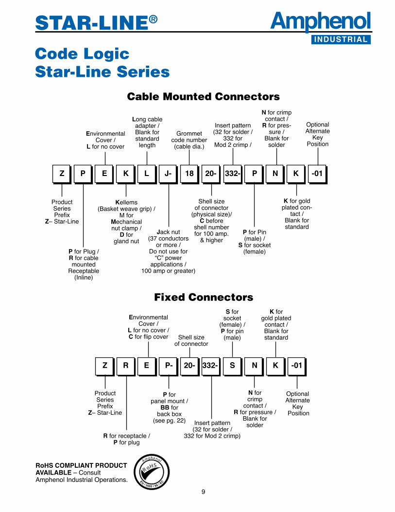
Code LogicStar-Line Series
Kellems(Basketweavegrip)/
MforMechanicalnut clamp /
Dforglandnut
332-Z P E K L J- 18 20- P N K -01
ProductSeriesPrefix
Z–Star-Line
PforPlug/Rforcablemounted
Receptable(Inline)
EnvironmentalCover/
Lfornocover
Longcableadapter/Blankforstandard
length
Jacknut(37 conductors
or more / Donotusefor
“C”powerapplications/
100 amp or greater)
Grommetcode number(cabledia.)
Shellsizeofconnector
(physicalsize)/Cbefore
shell numberfor 100 amp.
&higher
Insertpattern(32 for solder /
332 for Mod 2 crimp /
PforPin(male) /
Sforsocket(female)
N for crimpcontact/
Rforpres-sure/
Blankforsolder
Kforgoldplatedcon-
tact/Blankforstandard
OptionalAlternate
KeyPosition
Cable mounted Connectors
P forpanel mount /
BBforback box
(seepg.22)
Z R E P- 20- 332- S N K -01
Rforreceptacle/Pforplug
EnvironmentalCover/
Lfornocover/C for flip cover
Insertpattern(32 for solder /
332 for Mod 2 crimp)
Fixed ConnectorsS for
socket(female) /Pforpin(male)
N forcrimp
contact/Rforpressure/
Blankforsolder
K forgoldplated
contact/Blankforstandard
OptionalAlternate
KeyPosition
ProductSeriesPrefix
Z–Star-Line
Shellsizeofconnector
RoHS COMPLIANT PRODUCT AVAILABLE–ConsultAmphenol Industrial Operations.
RoHS
Amphenol
EU / 2002 / 95 / EC

AmphenolINDUSTRIAL
10
STAR-LINE®
Size Shell Cat. No. DIMENSIONS Catalog No. Cable Size With Standard WITH STANDARD CABLE ADAPTER With Jack Coupling Nut A B C Coupling Nut 12 ZPLD-▲-12-* 5-3/8 1-13/16 5-31/32 ZPLDJ-▲-12-* 16 ZPLD-▲-16-* 5-5/8 2-5/16 5-7/32 ZPLDJ-▲-16-* 20 ZPLD-▲-20-* 6-1/8 2-13/16 6-23/32 ZPLDJ-▲-20-* C20 ZPLD-▲-C20-* 6-5/8 2-13/16 7-7/32 ZPLDJ-▲-C20-* 24 ZPLD-▲-24-* 6-5/8 3-5/16 7-7/32 ZPLDJ-▲-24-* Select C24 ZPLD-▲-C24-* 7-1/8 3-5/16 7-23/32 ZPLDJ-▲-C24-* from 28 ZPLD-▲-28-* 7-1/8 3-13/16 7-23/32 ZPLDJ-▲-2�-*TableBelow C2� ZPLD-▲-C28-* 7-5/8 3-13/16 8-7/32 ZPLDJ-▲-C2�-* andSubstitute 12 ZPLDL-▲-12-* 7-5/8 1-13/16 8-7/32 ZPLDLJ-▲-12-*Symbol No. 16 ZPLDL-▲-16-* 7-7/8 2-5/16 8-15/32 ZPLDLJ-▲-16-*forDelta▲ 20 ZPLDL-▲-20-* 8-3/8 2-13/16 8-31/32 ZPLDLJ-▲-20-* C20 ZPLDL-▲-C20-* 8-7/8 2-13/16 9-15/32 ZPLDLJ-▲-C20-* 24 ZPLDL-▲-24-* 8-7/8 3-5/16 9-15/32 ZPLDLJ-▲-24-* C24 ZPLDL-▲-C24-* 9-3/8 3-5/16 9-31/32 ZPLDLJ-▲-C24-* 2� ZPLDL-▲-28-* 9-1/8 3-13/16 9-23/32 ZPLDLJ-▲-2�-* C2� ZPLDL-▲-C28-* 9-5/8 3-13/16 10-7/32 ZPLDLJ-▲-C2�-*
Straight plugwith Standard Compression Nut
To specify plug with environmental cover,changethirdletterinPartNo.“L’to“E’.Example: ZPLD changes to ZPED.
Shell Shell Shells Shells Shells Shell Shell Shell Shells Shells Cable Dia. 12 16 20 & C20 24 & C24 28 & C28 Cable Dia. 12 16 20 & C20 24 & C24 28 & C28
.062 to .125 02 – – – – 1.500 to 1.625 – – 26 26 26
.125 to .250 04 – – – – 1.625 to 1.750 – – 28 28 28
.250 to .375 06 06 – – – 1.750 to 1.875 – – 30 30 30
.375 to .500 08 08 – – – 1.875 to 1.937 – – 31 – –
.500 to .625 10 10 10 – – 1.937 to 2.000 – – – 32 32
.625 to .750 12 12 12 – – 2.000 to 2.125 – – – 34 34
.750 to .875 14 14 14 – – 2.125 to 2.250 – – – 36 36
.875 to .937 15 – – – – 2.250 to 2.375 – – – 38 38
.937 to 1.000 – 16 16 16 – 2.375 to 2.437 – – – 39 –1.000 to 1.125 – 18 18 18 – 2.437 to 2.500 – – – – 40
1.125 to 1.250 – 20 20 20 – 2.500 to 2.625 – – – – 421.250 to 1.375 – 22 22 22 – 2.625 to 2.750 – – – – 441.375 to 1.437 – 23 – – – 2.750 to 2.875 – – – – 461.437 to 1.500 – – 24 24 24
OIL-RESISTANT RUBBER GROMMETS—SYMBOL NUMBERS OF SIZES AVAILABLE Substitute the symbol number for the Delta ▲in the catalog number of plug. Example: ZPLD-▲ -12-* for .500 to .625 Dia. Cable changes to ZPLD-10 12-*
To specify a complete plug, substitute the Dash No. of the contact insert selected, for the Asterisk (*) in the Catalog No. below.
WITH LONG CABLE ADAPTER
Types ZPLD ZPED
A B
Safetywireholes(3) .062 DIA.
C
C
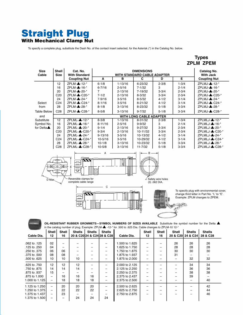
Size Shell Cat.No. DIMENSIONS CatalogNo. Cable Size WithStandard WITHSTANDARDCABLEADAPTER WithJack CouplingNut A B C D E CouplingNut 12 ZPLM-▲-12-* 6-1/8 1-13/16 6-23/32 2-3/8 1-3/4 ZPLMJ-▲-12-* 16 ZPLM-▲-16-* 6-7/16 2-5/16 7-1/32 3 2-1/4 ZPLMJ-▲-16-* 20 ZPLM-▲-20-* 7 2-13/16 7-19/32 3-3/4 2-3/4 ZPLMJ-▲-20-* C20 ZPLM-▲-C20-* 7-1/2 2-13/16 8-3/32 3-3/4 2-3/4 ZPLMJ-▲-C20-* 24 ZPLM-▲-24-* 7-9/16 3-5/16 8-5/32 4-1/2 3-1/4 ZPLMJ-▲-24-* Select C24 ZPLM-▲-C24-* 8-1/16 3-5/16 8-21/32 4-1/2 3-1/4 ZPLMJ-▲-C24-* from 28 ZPLM-▲-28-* 8-1/8 3-13/16 8-23/32 5-1/8 3-3/4 ZPLMJ-▲-28-*TableBelow C28 ZPLM-▲-C28-* 8-5/8 3-13/16 9-7/32 5-1/8 3-3/4 ZPLMJ-▲-C28-* andSubstitute 12 ZPLML-▲-12-* 8-3/8 1-13/16 8-31/32 2-3/8 1-3/4 ZPLMLJ-▲-12-*SymbolNo. 16 ZPLML-▲-16-* 8-11/16 2-5/16 9-9/32 3 2-1/4 ZPLMLJ-▲-16-*forDelta▲ 20 ZPLML-▲-20-* 9-1/4 2-13/16 9-27/32 3-3/4 2-3/4 ZPLMLJ-▲-20-* C20 ZPLML-▲-C20-* 9-3/4 2-13/16 10-11/32 3-3/4 2-3/4 ZPLMLJ-▲-C20-* 24 ZPLML-▲-24-* 9-13/16 3-5/16 10-13/32 4-1/2 3-1/4 ZPLMLJ-▲-24-* C24 ZPLML-▲-C24-* 10-5/16 3-5/16 10-29/32 4-1/2 3-1/4 ZPLMLJ-▲-C24-* 28 ZPLML-▲-28-* 10-1/8 3-13/16 10-23/32 5-1/8 3-3/4 ZPLMLJ-▲-28-* C28 ZPLML-▲-C28-* 10-5/8 3-13/16 11-7/32 5-1/8 3-3/4 ZPLMLJ-▲-C28-*
Straight Plugwith Mechanical Clamp Nut
Tospecifyplugwithenvironmentalcover,changethirdletterinPartNo.“L’to“E’.Example:ZPLMchangestoZPEM.
Shell Shell Shells Shells Shells Shell Shell Shell Shells Shells CableDia. 12 16 20&C2024&C2428&C28 CableDia. 12 16 20&C20 24&C24 28&C28
.062to.125 02 – – – – 1.500to1.625 – – 26 26 26
.125to.250 04 – – – – 1.625to1.750 – – 28 28 28
.250to.375 06 06 – – – 1.750to1.875 – – 30 30 30
.375to.500 08 08 – – – 1.875to1.937 – – 31 – –
.500to.625 10 10 10 – – 1.875to2.000 – – – 32 32
.625to.750 12 12 12 – – 2.000to2.125 – – – 34 34
.750to.875 14 14 14 – – 2.125to2.250 – – – 36 36
.875to.937 15 – – – – 2.250to2.375 – – – 38 38
.875to1.000 – 16 16 16 – 2.375to2.437 – – – 39 –1.000to1.125 – 18 18 18 – 2.375to2.500 – – – – 40
1.125to1.250 – 20 20 20 – 2.500to2.625 – – – – 421.250to1.375 – 22 22 22 – 2.625to2.750 – – – – 441.375to1.437 – 23 – – – 2.750to2.875 – – – – 461.375to1.500 – – 24 24 24
OIL-RESISTANT RUBBER GROMMETS—SYMBOL NUMBERS OF SIZESAVAILABLE Substitute the symbol number for the Delta▲inthecatalognumberofplug.Example:ZPLM-▲-12-*for.500to.625Dia.CablechangestoZPLM-1012-*
Tospecifyacompleteplug,substitutetheDashNo.ofthecontactinsertselected,fortheAsterisk(*)intheCatalogNo.below.
WITHLONGCABLEADAPTER
TypesZPLMZPEM
A
DMax. Reversibleclampsfor �completecablerange
E
B
Safetywireholes �(3).062DIA.
AmphenolINDUSTRIAL11STAR-LINE®

12
STAR-LINE®
CB
GSQ.
SafetyWireHoles(3).062Dia.
A
HSQ.
JHoleDia.
Straight Plugwith Conduit Adapter (for flexible conduit fittings) Tospecifyacompleteplug,substitutethedashno.ofthecontactinsertselectedfortheasterisk(*)Inthecatalogno.below.APLUGWITHJACKCOUPLINGNUTSHOULDBEUSEDWITHINSERTSHAVING37ORMORECONTACTS.
Shell Open CatalogNo. DIMENSIONS CatalogNo. Size Back WithStandard WithJack CouplingNut A B C G H J CouplingNut 12 ZPLP-12-* 2-3/8 1-13/16 2-31/32 1-17/64 1-5/8 3/16 ZPLPJ-12-* 16 ZPLP-16-* 2-13/32 2-5/16 3 1-11/16 2-1/8 7/32 ZPLPJ-16-* 20 ZPLP-20-* 2-7/16 2-13/16 3-1/32 2-3/32 2-5/8 9/32 ZPLPJ-20-* C20 ZPLP-C20-* 2-15/16 2-13/16 3-17/32 2-3/32 2-5/8 9/32 ZPLPJ-C20-* 24 ZPLP-24-* 2-15/32 3-5/16 3-1/16 2-17/32 3-1/8 11/32 ZPLPJ-24-* C24 ZPLP-C24-* 2-31/32 3-5/16 3-9/16 2-17/32 3-1/8 11/32 ZPLPJ-C24-* 28 ZPLP-28-* 2-15/32 3-13/16 3-1/16 3-1/32 3-3/4 11/32 ZPLPJ-28-* C28 ZPLP-C28-* 2-31/32 3-13/16 3-9/16 3-1/32 3-3/4 11/32 ZPLPJ-C28-*
Use with or without
Potting Sleeve
Tospecifyplugwithenvironmentalcover,changethirdletterinPartNo.“L”to“E”.Example:ZPLTchangestoZPET.
Shell Size CatalogNo. CatalogNo. Size Conduit WithStandard WithJack CouplingNut A B C D CouplingNut 12 3/4 ZPLT-212-* 4-1/4 1-13/16 4-27-32 3/4 ZPLTJ-212-* 16 1-1/4 ZPLT-416-* 4-3/8 2-5/16 4-31/32 1-1/4 ZPLTJ-416-* 20 1-1/2 ZPLT-520-* 4-1/2 2-13/16 5-3/32 1-1/2 ZPLTJ-520-* C20 1-1/2 ZPLT-5C20-* 5 2-13/16 5-19/32 1-1/2 ZPLTJ-5C20-* 24 2 ZPLT-624-* 4-5/8 3-5/16 5-7/32 2 ZPLTJ-624-* C24 2 ZPLT-6C24-* 5-1/8 3-5/16 5-23/32 2 ZPLTJ-6C24-* 28 2-1/2 ZPLT-728-* 5-3/32 3-13/16 5-11/16 2-1/2 ZPLTJ-728-* C28 2-1/2 ZPLT-7C28-* 5-19/32 3-13/16 6-3/16 2-1/2 ZPLTJ-7C28-*
DIMENSIONS
TypesZPLTZPET
AD �NPTThreadSize
B
SafetyWireHoles(3).062DIA.C
Straight Male PlugPanel MountTospecifyacompleteplug,substitutethedashno.ofthecontactinsertselectedfortheasterisk(*)inthecatalogno.below.APLUGWITHJACKCOUPLINGNUTSHOULDBEUSEDWITHINSERTSHAVING37ORMORECONTACTS. Types
ZPLPZPEP
Tospecifyplugwithenvironmentalcover,changethirdletterinPartNo.“L”to“E”.Example:ZPLPchangestoZPEP.

AmphenolINDUSTRIAL
13
STAR-LINE®
Shell Shell Shells Shells Shells Shell Shell Shell Shells ShellsCableDia. 12 16 20&C2024&C2428&C28 CableDia. 12 16 20&C20 24&C2428&C28
.062to.125 02 – – – – 1.500to1.625 – – 26 26 26
.125to.250 04 – – – – 1.625to1.750 – – 28 28 28
.250to.375 06 06 – – – 1.750to1.875 – – 30 30 30
.375to.500 08 08 – – – 1.875to1.937 – – 31 – –
.500to.625 10 10 10 – – 1.875to2.000 – – – 32 32
.625to.750 12 12 12 – – 2.000to2.125 – – – 34 34
.750to.875 14 14 14 – – 2.125to2.250 – – – 36 36
.875to.937 15 – – – – 2.250to2.375 – – – 38 38
.875to1.000 – 16 16 16 – 2.375to2.437 – – – 39 –1.000to1.125 – 18 18 18 – 2.437to2.500 – – – – 40
1.125to1.250 – 20 20 20 – 2.500to2.625 – – – – 421.250to1.375 – 22 22 22 – 2.625to2.750 – – – – 441.375to1.437 – 23 – – – 2.750to2.875 – – – – 461.375to1.500 – – 24 24 24
12 ZPLkL-▲-12-* 7-5/8 1-13/16 8-7/32 ZPLkJ-▲-12-* 16 ZPLkL-▲-16-* 7-7/8 2-5/16 8-15/32 ZPLkJ-▲-16-* 20 ZPLkL-▲-20-* 8-3/8 2-13/16 8-31/32 ZPLkJ-▲-20-* C20 ZPLkL-▲-C20-* 8-7/8 2-13/16 9-15/32 ZPLkJ-▲-C20-* 24 ZPLkL-▲-24-* 8-7/8 3-5/16 9-15/32 ZPLkJ-▲-24-* C24 ZPLkL-▲-C24-* 9-3/8 3-5/16 9-31/32 ZPLkJ-▲-C24-* 28 ZPLkL-▲-28-* 9-1/8 3-13/16 9-23/32 ZPLkJ-▲-28-* C28 ZPLkL-▲-C28-* 9-5/8 3-13/16 10-7/32 ZPLkJ-▲-C28-*
Selectfrom
TableBelowandSubsti-
tuteSymbolNo.forDelta▲ WITHLONGCABLEADAPTER
TypesZPLKZPEK
B
Safetywireholes(3).062DIA.
ASeecablegripcomponentspageforbasketweavegriplengths
C
Size Shell CatalogNo. DIMENSIONS CatalogNo. Cable Size WithStandard WITHSTANDARDCABLEADAPTER WithJack CouplingNut A B C CouplingNut 12 ZPLk-▲-12-* 5-3/8 1-13/16 5-31/32 ZPLkJ-▲-12-* 16 ZPLk-▲-16-* 5-5/8 2-5/16 6-7/32 ZPLkJ-▲-16-* 20 ZPLk-▲-20-* 6-1/8 2-13/16 6-23/32 ZPLkJ-▲-20-* C20 ZPLk-▲-C20-* 6-5/8 2-13/16 7-7/32 ZPLkJ-▲-C20-* 24 ZPLk-▲-24-* 6-5/8 3-5/16 7-7/32 ZPLkJ-▲-24-* C24 ZPLk-▲-C24-* 7-1/8 3-5/16 7-23/32 ZPLkJ-▲-C24-* 28 ZPLk-▲-28-* 7-1/8 3-13/16 7-23/32 ZPLkJ-▲-28-* C28 ZPLk-▲-C28-* 7-5/8 3-13/16 8-7/32 ZPLkJ-▲-C28-*
Straight Plugwith Basketweave Cable GripTospecifyacompleteplug,substitutetheDashNo.ofthecontactinsertselectedfortheasterisk(*)inthecatalogno.below.APLUGWITHJACKCOUPLINGNUTSHOULDBEUSEDWITHINSERTSHAVING37ORMORECONTACTS
Tospecifyplugwithenvironmentalcover,changethirdletterinPartNo.“L”to“E”.Example:ZPLkchangestoZPEk.
OIL-RESISTANTRUBBERGROMMETS—SYMBOLNUMBERSOFSIZESAVAILABLESubstitutethesymbolnumberfortheDelta▲inthecatalognumberofplug.Example:ZPLk-▲-12-*for.500to.625Dia.CablechangestoZPLk-1012-*

14
STAR-LINE®
In-Line Receptacle with Mechanical Clamp NutTospecifyacompletereceptacle,substitutethedashno.ofthecontactinsertselectedfortheasterisk(*)inthecatalogno.below.
OIL-RESISTANTRUBBERGROMMETS—SYMBOLNUMBERSOFSIZESAVAILABLESubstitutethesymbolnumberfortheDelta▲inthecatalognumberofplug.Example:ZRLM-▲-12-*for.500to.625Dia.cablechangestoZRLM-1012-*
Shell Shell Shells Shells Shells Shell Shell Shell Shells ShellsCableDia. 12 16 20&C2024&C2428&C28 CableDia. 12 16 20&C20 24&C24 28&C28
.062to.125 02 – – – – 1.500to1.625 – – 26 26 26
.125to.250 04 – – – – 1.625to1.750 – – 28 28 28
.250to.375 06 06 – – – 1.750to1.875 – – 30 30 30
.375to.500 08 08 – – – 1.875to1.937 – – 31 – –
.500to.625 10 10 10 – – 1.875to2.000 – – – 32 32
.625to.750 12 12 12 – – 2.000to2.125 – – – 34 34
.750to.875 14 14 14 – – 2.125to2.250 – – – 36 36
.875to.937 15 – – – – 2.250to2.375 – – – 38 38
.875to1.000 – 16 16 16 – 2.375to2.437 – – – 39 –1.000to1.125 – 18 18 18 – 2.437to2.500 – – – – 40
1.125to1.250 – 20 20 20 – 2.500to2.625 – – – – 421.250to1.375 – 22 22 22 – 2.625to2.750 – – – – 441.375to1.437 – 23 – – – 2.750to2.875 – – – – 461.375to1.500 – – 24 24 24
TypesZRLMZREM
Tospecifyreceptaclewiththreadedenvironmentalcover,changethirdletterinPartNo.“L”to“E”.Example:ZRLMchangestoZREM.
DIMENSIONS Size Shell Cat.No. Cable Size A C D E F G 12 ZRLM-▲-12-* 6-1/8 6-3/4 1-3/4 1-61/64 1-3/4 2-3/8 16 ZRLM-▲-16-* 6-7/16 7-1/16 2-1/4 2-31/64 2-1/4 3 20 ZRLM-▲-20-* 7 7-5/8 2-3/4 3-1/32 2-3/4 3-3/4 C20 ZRLM-▲-C20-* 7-1/2 8-1/8 2-3/4 3-1/32 2-3/4 3-3/4 24 ZRLM-▲-24-* 7-9/16 8-3/16 3-1/4 3-9/16 3-1/4 4-1/2 C24 ZRLM-▲-C24-* 8-1/16 8-11/16 3-1/4 3-9/16 3-1/4 4-1/2 28 ZRLM-▲-28-* 8-1/8 8-3/4 3-3/4 4-1/16 3-3/4 5-1/8 C28 ZRLM-▲-C28-* 8-5/8 9-1/4 3-3/4 4-1/16 3-3/4 5-1/8WITHLONGCABLEADAPTER 12 ZRLML-▲-12-* 8-3/8 9 1-3/4 1-61/64 1-3/4 2-3/8 16 ZRLML-▲-16-* 8-11/16 9-5/16 2-1/4 2-31/64 2-1/4 3 20 ZRLML-▲-20-* 9-1/4 9-7/8 2-3/4 3-1/32 2-3/4 3-3/4 C20 ZRLML-▲-C20-* 9-3/4 10-3/8 2-3/4 3-1/32 2-3/4 3-3/4 24 ZRLML-▲-24-* 9-13/16 10-7/16 3-1/4 3-9/16 3-1/4 4-1/2 C24 ZRLML-▲-C24-* 10-5/16 10-15/16 3-1/4 3-9/16 3-1/4 4-1/2 28 ZRLML-▲-28-* 10-1/8 10-3/4 3-3/4 4-1/16 3-3/4 5-1/8 C28 ZRLML-▲-C28-* 10-5/8 11-1/4 3-3/4 4-1/16 3-3/4 5-1/8
Selectfrom
TableBelowandSubsti-
tuteSymbolNo.forDelta▲
A

AmphenolINDUSTRIAL
15
STAR-LINE®
In-Line Receptaclewith Standard Compression NutTo specify a complete receptacle, substitute the dash no. of the contact insert selected for the asterisk (*) in the catalog no. below.
Dimensions Size Shell Cat.No. Cable Size A C D E 12 ZRLD-▲-12-* 5-3/8 6 1-3/4 1-61/64 16 ZRLD-▲-16-* 5-5/8 6-1/4 2-1/4 2-31/64 20 ZRLD-▲-20-* 6-1/8 6-3/4 2-3/4 3-1/32 C20 ZRLD-▲-C20-* 6-5/8 7-1/4 2-3/4 3-1/32 24 ZRLD-▲-24-* 6-5/8 7-1/4 3-1/4 3-9/16 C24 ZRLD-▲-C24-* 7-1/8 7-3/4 3-1/4 3-9/16 28 ZRLD-▲-28-* 7-1/8 7-3/4 3-3/4 4-1/16 C28 ZRLD-▲-C28-* 7-5/8 8-1/4 3-3/4 4-1/16 12 ZRLDL-▲-12-* 7-5/8 8-1/4 1-3/4 1-61/64 16 ZRLDL-▲-16-* 7-7/8 8-1/2 2-1/4 2-31/64 20 ZRLDL-▲-20-* 8-3/8 9 2-3/4 3-1/32 C20 ZRLDL-▲-C20-* 8-7/8 9-1/2 2-3/4 3-1/32 24 ZRLDL-▲-24-* 8-7/8 9-1/2 3-1/4 3-9/16 C24 ZRLDL-▲-C24-* 9-3/8 10 3-1/4 3-9/16 28 ZRLDL-▲-28-* 9-1/8 9-3/4 3-3/4 4-1/16 C28 ZRLDL-▲-C28-* 9-5/8 10-1/4 3-3/4 4-1/16
Shell Shell Shells Shells Shells Shell Shell Shell Shells ShellsCableDia. 12 16 20&C2024&C2428&C28 CableDia. 12 16 20&C20 24&C2428&C28
.062to.125 02 – – – – 1.500to1.625 – – 26 26 26
.125to.250 04 – – – – 1.625to1.750 – – 28 28 28
.250to.375 06 06 – – – 1.750to1.875 – – 30 30 30
.375to.500 08 08 – – – 1.875to1.937 – – 31 – –
.500to.625 10 10 10 – – 1.875to2.000 – – – 32 32
.625to.750 12 12 12 – – 2.000to2.125 – – – 34 34
.750to.875 14 14 14 – – 2.125to2.250 – – – 36 36
.875to.937 15 – – – – 2.250to2.375 – – – 38 38
.875to1.000 – 16 16 16 – 2.375to2.437 – – – 39 –1.000to1.125 – 18 18 18 – 2.437to2.500 – – – – 40
1.125to1.250 – 20 20 20 – 2.500to2.625 – – – – 421.250to1.375 – 22 22 22 – 2.625to2.750 – – – – 441.375to1.437 – 23 – – – 2.750to2.875 – – – – 461.375to1.500 – – 24 24 24
Selectfrom
TableBelowandSubsti-
tuteSymbolNo.forDelta▲
With Long Cable Adapter
TypesZRLDZRED
SafetyWireHoles(3).062Dia.
D
E
A
C
Tospecifyreceptaclewiththreadedenvironmentalcover,changethirdletterinPartNo.“L”to“E”.Example:ZRLDchangestoZRED.
OIL-RESISTANTRUBBERGROMMETS—SYMBOLNUMBERSOFSIZESAVAILABLESubstitutethesymbolnumberfortheDelta▲inthecatalognumberofplug.Example:ZRLD-▲-12-*for.500to.625Dia.cablechangestoZRLD-1012-*

16
STAR-LINE®
SafetyWireHoles(3).062Dia.
D
E
ASeecablegripcomponentspageforbasketweavegriplengths
TypesZRLKZREK
Shell Shell Shells Shells Shells Shell Shell Shell Shells ShellsCableDia. 12 16 20&C2024&C2428&C28 CableDia. 12 16 20&C20 24&C2428&C28
.062to.125 02 – – – – 1.500to1.625 – – 26 26 26
.125to.250 04 – – – – 1.625to1.750 – – 28 28 28
.250to.375 06 06 – – – 1.750to1.875 – – 30 30 30
.375to.500 08 08 – – – 1.875to1.937 – – 31 – –
.500to.625 10 10 10 – – 1.875to2.000 – – – 32 32
.625to.750 12 12 12 – – 2.000to2.125 – – – 34 34
.750to.875 14 14 14 – – 2.125to2.250 – – – 36 36
.875to.937 15 – – – – 2.250to2.375 – – – 38 38
.875to1.000 – 16 16 16 – 2.375to2.437 – – – 39 –1.000to1.125 – 18 18 18 – 2.437to2.500 – – – – 40
1.125to1.250 – 20 20 20 – 2.500to2.625 – – – – 421.250to1.375 – 22 22 22 – 2.625to2.750 – – – – 441.375to1.437 – 23 – – – 2.750to2.875 – – – – 461.375to1.500 – – 24 24 24
In-Line Receptaclewith Basketweave Cable GripTo specify a complete receptacle, substitute the dash no. of the contact insert selected for the asterisk (*) in the catalog no. below.
OIL-RESISTANTRUBBERGROMMETS—SYMBOLNUMBERSOFSIZESAVAILABLESubstitutethesymbolnumberfortheDelta▲inthecatalognumberofplug.Example:ZRLk-▲-12-*for.500to.625Dia.cablechangestoZRLk-1012-*
Dimensions Size Shell Cat.No. Cable Size A C D E 12 ZRLk-▲-12-* 5-3/8 6 1-3/4 1-61/64 16 ZRLk-▲-16-* 5-5/8 6-1/4 2-1/4 2-31/64 20 ZRLk-▲-20-* 6-1/8 6-3/4 2-3/4 3-1/32 C20 ZRLk-▲-C20-* 6-5/8 7-1/4 2-3/4 3-1/32 24 ZRLk-▲-24-* 6-5/8 7-1/4 3-1/4 3-9/16 C24 ZRLk-▲-C24-* 7-1/8 7-3/4 3-1/4 3-9/16 28 ZRLk-▲-28-* 7-1/8 7-3/4 3-3/4 4-1/16 C28 ZRLk-▲-C28-* 7-5/8 8-1/4 3-3/4 4-1/16 12 ZRLkL-▲-12-* 7-5/8 8-1/4 1-3/4 1-61/64 16 ZRLkL-▲-16-* 7-7/8 8-1/2 2-1/4 2-31/64 20 ZRLkL-▲-20-* 8-3/8 9 2-3/4 3-1/32 C20 ZRLkL-▲-C20-* 8-7/8 9-1/2 2-3/4 3-1/32 24 ZRLkL-▲-24-* 8-7/8 9-1/2 3-1/4 3-9/16 C24 ZRLkL-▲-C24-* 9-3/8 10 3-1/4 3-9/16 28 ZRLkL-▲-28-* 9-1/8 9-3/4 3-3/4 4-1/16 C28 ZRLkL-▲-C28-* 9-5/8 10-1/4 3-3/4 4-1/16
Selectfrom
TableBelowandSubsti-
tuteSymbolNo.forDelta▲
With Long Cable Adapter
Tospecifyreceptaclewiththreadedenvironmentalcover,changethirdletterinPartNo.“L”to“E”.Example:ZRLkchangestoZREk.
C

AmphenolINDUSTRIAL
17
STAR-LINE®
Dimensions Shell Size Size Conduit Cat.No. A B C D E 12 3/4 ZRLT-212-* 4-1/4 3/4 4-7/8 1-3/8 1-61/64 16 1-1/4 ZRLT-416-* 4-3/8 1-1/4 5 2-1/4 2-15/32 20 1-1/2 ZRLT-520-* 4-1/2 1-1/2 5-1/8 2-3/4 3-1/32 C20 1-1/2 ZRLT-5C20-* 5 1-1/2 5-5/8 2-3/4 3-1/32 24 2 ZRLT-624-* 4-5/8 2 5-1/4 3-1/4 3-9/16 C24 2 ZRLT-6C24 5-1/8 2 5-3/4 3-1/4 3-9/16 28 2-1/2 ZRLT-728-* 5-3/32 2-1/2 5-23-32 3-3/4 4-1/16 C28 2-1/2 ZRLT-7C28-* 5-19/32 2-1/2 6-7/32 3-3/4 4-1/16
In-Line Receptaclewith Conduit Adapter(for flexible conduit fittings)
To specify a complete receptacle, substitute the dash no. of the contact insert selected, for the asterisk (*) in the catalog no. below. To specify receptacle with threaded environmental cover, change third letter in part no. “L” to “E””.
TypesZRLTZRET
Tospecifyreceptaclewiththreadedenvironmentalcover,changethirdletterinPartNo.“L”to“E”.Example:ZRLTchangestoZRET.
A
B�NPT�Thread
D
E
SafetyWireHoles�(3).062Dia.
C
B�NPT�Thread

18
STAR-LINE®
G
5/8FN Maxpanelthickness �
whenbackmounted �usingjacknut�plugs.**
1/16"GasketFits �frontorback�offlange.
Square Flange Receptacle Tospecifyacompletereceptacle,substitutethedashno.ofthecontactinsertselected,fortheasterisk(*)inthecatalogno.below.
TypesZRLPZRCPZREP
Drillholeinpanel1/64”largerthanDimension“k”forfrontmountingordimension“C”forbackmounting**Maximumpanelthicknessmaybeincreased1/8”whenusingStandardCouplingNutPlugs.
E �hole �Dia.
ASq.BSq.
LJ
3/16
C
Modified �Acme �thread
k
WITHTHREADEDENVIRONMENTALCOVERANDSASHCHAIN
WITHHINGEDSPRINGCOVER
Tospecifyreceptaclewithspringdoorcover,changethirdletterinpartnumberfrom“L”to“C”.Example:ZRLPchangestoZRCP.
Tospecifyreceptaclewiththreadedenvironmentalcover,changethirdletterinpartnumberfrom“L”to“E”.Example:ZRLPchangestoZREP.
12 Usewith ZRLP-12-* 1-3/4 1-3/8 1-1/12 11/64 2-15/16 2-1/8 1 1-11/32 2-21/64 1/4 16 orwithout ZRLP-16-* 2-1/4 1-11/16 2 13/64 2-15/16 2-1/8 1 1-27/32 2-21/64 1/4 20 Potting ZRLP-20-* 2-3/4 2-3/32 2-1/2 7/32 2-15/16 2-3/16 1 2-11/32 2-21/64 1/4 C20 Sleeves ZRLP-C20-* 2-3/4 2-3/32 2-1/2 7/32 3-7/16 2-11/16 1-1/2 2-11/32 2-53/64 3/4 24 ZRLP-24-* 3-1/4 2-17/32 3 9/32 2-15/16 2-3/16 1 2-27/32 2-21/64 1/4 C24 ZRLP-C24-* 3-1/4 2-17/32 3 9/32 3-7/16 2-11/16 1-1/2 2-27/32 2-53/64 3/4 28 ZRLP-28-* 3-3/4 3-1/32 3-1/2 11/32 2-15/16 2-3/16 1 3-11/32 2-21/64 1/4 C28 ZRLP-C28* 3-3/4 3-1/32 3-1/2 11/32 3-7/16 2-11/16 1-1/2 3-11/32 2-53/64 3/4
DIMENSIONS Shell Open WITHSTANDARDCABLEADAPTER Size Back CatalogNo. A B C* E F G J K L N
E �HoleDia.


20
STAR-LINE®
Square Flange Receptaclewith Basketweave Cable GripTo specify a complete receptacle, substitute the dash no. of the contact insert selected for the asterisk (*) in the catalog no. below.
Dimensions Size Shell Catalog Cable Size Number A B C D E F G 12 ZRLPk-▲-12-* 5-3/8 1-3/4 6 1-3/8 11/64 1-1/2 1/4 16 ZRLPk-▲-16-* 5-5/8 2-1/4 6-1/4 1-11/16 13/64 2 1/4 20 ZRLPk-▲-20-* 6-1/8 2-3/4 6-3/4 2-3/32 7/32 2-1/2 1/4 C20 ZRLPk-▲-C20-* 6-5/8 2-3/4 7-1/4 2-3/32 7/32 2-1/2 3/4 24 ZRLPk-▲-24-* 6-5/8 3-1/4 7-1/4 2-17/32 9/32 3 1/4 C24 ZRLPk-▲-C24-* 7-1/8 3-1/4 7-3/4 2-17/32 9/3 3 3/4 28 ZRLPk-▲-28-* 7-1/8 3-3/4 7-3/4 3-1/32 11/32 3-1/2 1/4 C28 ZRLPk-▲-C28-* 7-5/8 3-3/4 8-1/4 3-1/32 11/32 3-1/2 3/4 WithLongCableAdapter 12 ZRLPkL-▲-12-* 7-5/8 1-3/4 8-1/4 1-3/8 11/64 1-1/2 1/4 16 ZRLPkL-▲-16-* 7-7/8 2-1/4 8-1/2 1-11/16 13/64 2 1/4 20 ZRLPkL-▲-20-* 8-3/8 2-3/4 9 2-3/32 7/32 2-1/2 1/4 C20 ZRLPkL-▲-C20-* 8-7/8 2-3/4 9-1/2 2-3/32 7/32 2-1/2 3/4 24 ZRLPkL-▲-24-* 8-7/8 3-1/4 9-1/2 2-17/32 9/32 3 1/4 C24 ZRLPkL-▲-C24-* 9-3/8 3-1/4 10 2-17/32 9/32 3 3/4 28 ZRLPkL-▲-28-* 9-1/8 3-3/4 9-3/4 3-1/32 11/32 3-1/2 1/4 C28 ZRLPkL-▲-C28-* 9-5/8 3-3/4 10-1/4 3-1/32 11/32 3-1/2 1/4
Selectfrom
TableBelowandSubsti-
tuteSymbolNo.forDelta▲
A
F
C
G
E �HoleDia.
Tospecifyreceptaclewiththreadedenviron-mentalcover,changethirdletterinPartNo.“L”to“E”.Example:ZRLPkchangestoZREPR.
Tospecifyreceptaclewithspringdoorcover,changethirdletterinPartNo.“L”to“C”.Example:ZRLPMchangestoZRCPR.
Shell Shell Shells Shells Shells Shell Shell Shell Shells ShellsCableDia. 12 16 20&C2024&C2428&C28 CableDia. 12 16 20&C20 24&C2428&C28
.062to.125 02 – – – – 1.500to1.625 – – 26 26 26
.125to.250 04 – – – – 1.625to1.750 – – 28 28 28
.250to.375 06 06 – – – 1.750to1.875 – – 30 30 30
.375to.500 08 08 – – – 1.875to1.937 – – 31 – –
.500to.625 10 10 10 – – 1.875to2.000 – – – 32 32
.625to.750 12 12 12 – – 2.000to2.125 – – – 34 34
.750to.875 14 14 14 – – 2.125to2.250 – – – 36 36
.875to.937 15 – – – – 2.250to2.375 – – – 38 38
.875to1.000 – 16 16 16 – 2.375to2.437 – – – 39 –1.000to1.125 – 18 18 18 – 2.437to2.500 – – – – 40
1.125to1.250 – 20 20 20 – 2.500to2.625 – – – – 421.250to1.375 – 22 22 22 – 2.625to2.750 – – – – 441.375to1.437 – 23 – – – 2.750to2.875 – – – – 461.375to1.500 – – 24 24 24
Drillholeinpanel1/64”largerthanDimension“H”forbackmounting..
OIL-RESISTANTRUBBERGROMMETS—SYMBOLNUMBERSOFSIZESAVAILABLESubstitutethesymbolnumberfortheDelta▲inthecatalognumberofplug.Example:ZRLk-▲-12-*for.500to.625Dia.cablechangestoZREk-1012-*
ZRLPK,ZRCPK,ZREPK

AmphenolINDUSTRIAL
21
STAR-LINE®
Shell Hub Dimensions Size Size† Cat.No. A B C D E F G H 3/4 ZRLBB-212-* 5-1/4 4-5/8 4-3/16 3-9/16 2-3/8 2-13/16 2-7/16 9/32 1 ZRLBB-312-* 5-1/4 4-5/8 4-3/16 3-9/16 2-3/8 2-13/16 2-7/16 9/32 1 ZRLBB-316-* 5-1/4 4-5/8 4-3/16 3-9/16 2-3/8 2-15/16 2-17/32 9/32 1-1/4 ZRLBB-416-* 5-1/4 4-5/8 4-3/16 3-9/16 2-5/8 2-15/16 2-17/32 9/32 1-1/2 ZRLBB-516-* 5-1/4 4-5/8 4-3/16 3-9/16 2-5/8 2-15/16 2-17/32 9/32 1-1/4 ZRLBB-420-* 6 5-1/4 4-1/2 3-7/8 3-3/4 3-39/64 3 9/32 1-1/2 ZRLBB-520-* 6 5-1/4 4-1/2 3-7/8 3-3/4 3-39/64 3 9/32 2 ZRLBB-620-* 6 5-1/4 4-1/2 3-7/8 3-3/4 3-39/64 3 9/32 1-1/4 ZRLBB-4C20-* 6 5-1/4 4-1/2 3-7/8 3-3/4 3-39/64 3-3/8 9/32 1-1/2 ZRLBB-5C20-* 6 5-1/4 4-1/2 3-7/8 3-3/4 3-39/64 3-3/8 9/32 2 ZRLBB-6C20-* 6 5-1/4 4-1/2 3-7/8 3-3/4 3-39/64 3-3/8 9/32 2-1/2 ZRLBB-724-* 8 7 3-3/4 3-33/64 2-19/64 7/16 3 ZRLBB-824-* 8 7 4-1/2 3-33/64 2-19/64 7/16 2-1/2 ZRLBB-7C24-* 8 7 3-3/4 3-33/64 2-21-32 7/16 3 ZRLBB-8C24-* 8 7 4-1/2 3-33-64 2-21-32 7/16 2-1/2 ZRLBB-728-* 8 7 3-3/4 3-1/2 2-7/64 7/16 3 ZRLBB-828-* 8 7 4-1/2 3-1/2 2-7/64 7/16 2-1/2 ZRLBB-7C28-* 8 7 3-3/4 3-1/2 2-15/32 7/16 3 ZRLBB-8C28-* 8 7 4-1/2 3-1/2 2-15/32 7/16
Receptacle Mounted to Junction Boxwith Angle Adapter
SeeDrawingBelow
12
16
20
C20
24
C24
28
C28
TypesZRLBBZRCBBZREBB
SHELLSIZES12-16-20-C20 SHELLSIZES24-C24-28-C28
Tospecifyacompletereceptacle,substitutethedashno.ofthecontactinsertselected,fortheasterisk(*)inthecatalogno.below.
HUB �SIZE
DCBA
H
A C DB
E F
G
8 H
9-1/2
5/8
5/8
6-3/4HUB �SIZE 5-3/8
87
�
Tospecifyreceptaclewithspringdoorcover,changethirdletterinpartnumberfrom“L”to“C”.Example:ZRLBBchangestoZRCBB
Tospecifyreceptaclewiththreadedenvironmentalcover,changethirdletterinpartnumberfrom“L”to“E”.Example:ZRLBBchangestoZREBB
WITHTHREADEDENVIRONMENTALCOVERANDSASHCHAIN
WITHHINGEDSPRINGCOVER
†Otherhubsizesareavailable.ConsultAmphenolIndustrialOperations.

Receptacle Mounted to Junction Boxwith Straight AdapterTospecifyacompletereceptacle,substitutethedashno.ofthecontactinsertselected,fortheasterisk(*)inthecatalogno.below. Types
ZRLAZRCAZREA
Shell Hub Dimensions Size Size† Cat.No. A B C D E F G H 3/4 ZRLA-212-* 5-1/4 4-5/8 4-3/16 3-9/16 2-3/8 1-27/32 1 9/32 1 ZRLA-312-* 5-1/4 4-5/8 4-3/16 3-9/16 2-3/8 1-27/32 1 9/32 1 ZRLA-316-* 5-1/4 4-5/8 4-3/16 3-9/16 2-3/8 1-27/32 1 9/32 1-1/4 ZRLA-416-* 5-1/4 4-5/8 4-3/16 3-9/16 2-5/8 1-27/32 1 9/32 1-1/2 ZRLA-516-* 5-1/4 4-5/8 4-3/16 3-9/16 2-5/8 1-27/32 1 9/32 1-1/4 ZRLA-420-* 6 5-1/4 4-1/2 3-7/8 3-3/4 3-1/16 1-7/32 9/32 1-1/2 ZRLA-520-* 6 5-1/4 4-1/2 3-7/8 3-3/4 3-1/16 1-7/32 9/32 2 ZRLA-6-20-* 6 5-1/4 4-1/2 3-7/8 3-3/4 3-1/16 1-7/32 9/32 1-1/4 ZRLA-4C20-* 6 5-1/4 4-1/2 3-7/8 3-3/4 2-9/16 1-7/32 9/32 1-1/2 ZRLA-5C20-* 6 5-1/4 4-1/2 3-7/8 3-3/4 2-9/16 1-7/32 9/32 2 ZRLA-6C20-* 6 5-1/4 4-1/2 3-7/8 3-3/4 2-9/16 1-7/32 9/32 2-1/2 ZRLA-724-* 8 7 3-3/4 2-11/32 1-1/2 7/16 3 ZRLA-824-* 8 7 4-1/2 2-11/32 1-1/2 7/16 2-1/2 ZRLA-7C24-* 8 7 3-3/4 2-27/32 1-1/2 7/16 3 ZRLA-8C24-* 8 7 4-1/2 3-33-64 1-1/2 7/16 2-1/2 ZRLA-728-* 8 7 3-3/4 2-27/32 1-1/2 7/16 3 ZRLA-828-* 8 7 4-1/2 2-9/32 1-1/2 7/16 2-1/2 ZRLA-7C28-* 8 7 3-3/4 2-25/32 1-1/2 7/16 3 ZRLA-8C28-* 8 7 4-1/2 2-25/32 1-1/2 7/16
SeeDrawingBelow
12
16
20
C20
24
C24
28
C28
SHELLSIZES12-16-20-C20 SHELLSIZES24-C24-28-C28
Tospecifyreceptaclewithspringdoorcover,changethirdletterinpartnumberfrom“L”to“C”.Example:ZRLAchangestoZRCA.
Tospecifyreceptaclewiththreadedenvironmentalcover,changethirdletterinpartnumberfrom“L”to“E”.Example:ZRLAchangestoZREA.
WITHTHREADEDENVIRONMENTALCOVERANDSASHCHAIN
WITHHINGEDSPRINGCOVER
HUB �SIZE
DCBA
H
A C DB
E F
G
8 H
9-1/2
5/8
5/8
6-3/4HUB �SIZE 5-3/8
87
�
†Otherhubsizesareavailable.ConsultAmphenolIndustrialOperations.
22
STAR-LINE®

Amphenol® Star-Line EX®
Product Instructions
SectionsContents:• HazardousLocationPage• PartNumberGuide• EXGlandCodeGuide• EX-13Plug• EX-15InlineReceptacle• EX-17PanelMountReceptacle• Familiarization&AssemblyInformation• Assembly&Termination• MixingInstructions• PottingInstructions
23
AmphenolINDUSTRIAL
STAR-LINE EX®

IntrinsicSafety iaibic
60079-1160079-1160079-11
Zone0Zone1Zone2
iaDibD
61241-1161241-11
Zone20Zone21
123
Flameproof d 60079-1 Zone1 2
Enclosure tD 61241-1 Zone20,21,22
Purge&Pressurization pxpypz
60079-260079-260079-2
Zone1Zone1Zone2
223
Pressurized pD 612441-4 Zone21,22
IncreasedSafety e 60079-7 Zone1 2
Encapsulation mamb
60079-1860079-18
Zone0Zone1
maDmbD
61241-1861241-18
Zone20Zone21
12
OilImmersion o 60079-6 Zone1 2
PowderFilled q 60079-5 Zone1 2
NonIncendive nA,nC,nL,nR 60079-15 Zone2 3
Rooms(draft) p 60079-13 Zone1 2
OpticalRadiation op.. 60079-28 Zone0 1
Star-Line EX® Hazardous Certification Information
ProtectionMethodIEC/EN(ATEX)ATEX ExCodeGasExCodeDustCategory
Temperature RatingsUEC,EU(Europe) SurfaceUSA(NEC505) TemperatureCanada
85C(185F) T6
Hazardous Area Equipment Mark
MarkingsforIEC/EN(ATEX)IEC/ATEX(76/117/EEC)
Explosionprotection Protectionmethod GasGroup TemperatureClass EquipmentProtectionLevel ExdIICT6 Gb
European(EU)ATEXDirective(94/9/EC)CEmarking ID#ofNotifiedBodyfortheQASystem EUExplosiveAtmospheresymbol Aboveground Category Gas,Dust 0518 II 2GD
Ingress Protection(IP) Ratings
0NoProtection0NoProtection
1Objectsgreaterthan50mm1Verticallydrippingwater
2Objectsgreaterthan12mm275to90drippingwater
3Objectsgreaterthan2.5mm3Sprayedwater
4Objectsgreaterthan1mm4Splashedwater
5Dust-protected5Waterjets
6Dust-tight6HeavySeas
7Temporaryimmersion
FirstNumberSecondNumberProtectionagainstsolidbodiesProtectionagainstLiquids
6Dust-tight
8Indefiniteimmersion
HazLoc Hand Chart
*
*
*
Flameproof d 60079-1 2
IncreasedSafety e 60079-7 Zone1 2Note:Star-LineEx®
productscertificationdenotedwitha*.
*
*
*
***
Enclosure tD 61241-1 Zone20,21,22
GeneralRequirements
Class.ofHazardousAreasElectricalInstallations
60079-0
60079-160079-14
61241-0
450C(842F)T1 300C(572F)T2 200C(392F)T3 135C(275F)T4 100C(212F)T5*
Inspection&Maintenance 60079-17
24
STAR-LINE EX®

Code Logic Star-Line EX
EX 13 3
ProductSeriesPrefix
13forMalePlug/15forFemaleInline/
17forFemalePanelMount18forPanelMountCircularFlange
19forThruBulkhead-DualMateReceptacle
“##”codeforgrommetsusedw/type“2”or“4”
hardwarestyles(Seepage67)/Lettercodedesignationfor
EExdglandsizes(seechartbelow)
Example:EX-13-3-C-20-332PNMalePlugwithEEXglandforacablewith0.95”24.1mmO.D.,20ea#12awg/4mm2malecontacts.EX-15-4-1620-332SNFemaleInlinewithbasketweavegripforacablewith0.95”24.1mmO.D.,20ea#12awg/4mm2femalecontacts.EX-17-1-20-332SNFemalePanelMount,20ea#12awg/4mm2femalecontacts.EX-13-3-C-16-22PR-BSMalePlugwithEEXglandforanarmoredcablewith1.25”/31.75mmO.D.,4ea#4awg/25mm2malecontacts.EX-17-3-C-16-22SR-BSFemalePanelMountwithcableadapterwithandEEXglandforanarmoredandsheathedcable.
ForAmphenolStar-Lineproductinsertde-ratinginformationpertheNationalElectricCode,pleaseconsulttheAmphenolIndustrialwebsite,www.amphenol-industrial.com.ChartislocatedunderLITERATUREtab.
C
ConnectorShellSize
(12,16,20,24,28,C20,C24,C28)
20 332 P N -BS
InsertConfiguration
ContactGenderPforMalePin/
SforFemaleSocket
OptionalAlternate
KeyPositions
TerminationMethodNforcrimpcontact/
Rforpressure/Blankforsolder
CableTypeOmitifunarmored.
-BSor-BSR(seecabletype
inchartsonnextpage)
-01
HardwareStyle
(seepgs.25-28)
Callouttodesignate
T5temperaturerating
-20oCto55oC
A376S
BlankAluminumS=StainlessSteel
B=Brass
AmphenolINDUSTRIAL
STAR-LINE EX®
25


EExd Unarmored Armored&Sheathed Armored&Sheathed Cable Cable Cable withreducedbore Gland Nodeviationif -BS -BSR SizeCode Unarmored UA Standard OD-Reduced Min Max Min Max Min Max Min Max
EEx d Cable Types
Star-LineEXPlugwithEXGland
Amphenoloffersanextensivelineofexplosionproofandgeneraldutycableglands.ConsultAmphenolIndustrialOperationsandaskfornewcatalog12-055,AmphenolCableGlandsandCordGrips.
CablescanbedesignedwithacustomovermoldtoanyAmphenolcylindricalconnectorforanyindustrialapplication.ConsultAmphenolIndustrialOperationsforfurtherinformation.
A1 .1575(4.0) .3307(8.4) .1339(3.4) .3307(8.4) .3543(9.0) .5315(13.5) .2638(6.7) .4055(10.3) A2 .2835(7.2) .4606(11.7) .2835(7.2) .4606(11.7) .4528(11.5) .6299(16.0) .3701(9.4) .4921(12.5) A .3780(9.6) .5512(14.0) .3701(9.4) .5512(14.0) .6102(15.5) .8307(21.1) .4724(12.0) .6929(17.6) B .5315(13.5) .7874(20.0) .5315(13.5) .7874(20.0) .7992(20.3) 1.079(27.4) .6614(16.8) .9409(23.9) C .7677(19.5) 1.035(26.3) .7677(19.5) 1.035(26.3) 1.051(26.7) 1.339(34.0) .9134(23.2) 1.201(30.5) C2 .9055(23.0) 1.268(32.2) .9055(23.0) 1.268(32.2) 1.299(33.0) 1.598(40.6) 1.126(28.6) 1.425(36.2) D 1.110(28.2) 1.504(38.2) 1.106(28.1) 1.504(38.2) 1.551(39.4) 1.839(46.7) 1.370(34.8) 1.669(42.4) D2 1.307(33.2) 1.736(44.1) 1.303(33.1) 1.736(44.1) 1.799(45.7) 2.094(53.2) 1.618(41.1) 1.909(48.5) E 1.547(39.3) 1.972(50.1) 1.543(39.2) 1.969(50.0) 2.051(52.1) 2.343(59.5) 1.870(47.5) 2.157(54.8) E2 1.839(46.7) 2.205(56.0) 1.839(46.7) 2.205(56.0) 2.299(58.4) 2.591(65.8) 2.118(53.8) 2.409(61.2) F 2.059(52.3) 2.441(62.0) 2.051(52.1) 2.441(62.0) 2.551(64.8) 2.843(72.2) 2.370(60.2) 2.677(68.0) F2 2.287(58.1) 2.677(68.0) 2.283(58.0) 2.677(68.0) 2.799(71.1) 3.071(78.0) 2.618(66.5) 2.890(73.4) G 2.453(62.3) 2.835(72.0) 2.449(62.2) 2.835(72.0) 3.031(77.0) 3.307(84.0) –
AmphenolINDUSTRIAL
STAR-LINE EX®
27

Plug with Mechanical Clamp (POTTINGREQUIRED) EX-13-2 Style
Hardware
Dimension A* B* C D E F Shell 12 7-7/16(189) 3-9/16(91) 2-1/8(54) 2(51) 15/16(24) 2-3/8(60) 16 9-1/2(241) 3-9/16(91) 2-5/8(67) 2-1/16(52) 1-7/16(37) 3(76) 20 9-9/16(243) 3-9/16(91) 3-1/8(79) 2-1/8(54) 1-15/16(49) 3-3/4(95) 24 9-5/8(245) 3-9/16(91) 3-5/8(92) 2-3/16(56) 2-7/16(62) 4-1/2(114) 28 9-11/16(246) 3-9/16(91) 4-1/8(105) 21/4(57) 2-7/8(73) 5-1/8(130)
Plug with EEx d Gland (POTTINGISNOTREQUIRED) EX-13-3 StyleNote: ‘D’Dimensionvariesaccordingtocablegland.Detailedcabledimensionsandtyperequired.
Glandisincludedwiththeconnector.
Dimension A* B* C Gland Shell Thread 12 6-1/16(154) 3-9/16(91) 2-1/8(54) M25 16 8-1/16(205) 3-9/16(91) 2-5/8(67) M40 20 8-1/16(205) 3-9/16(91) 3-1/8(79) M50 24 8-1/16(205) 3-9/16(91) 3-5/8(92) M63 28 8-1/16(205) 3-9/16(91) 4-1/8(105) M75
Plug with Basketweave Cable Grip (POTTINGREQUIRED) EX-13-4 Style
Dimension A* B* C D E F G Shell 12 6-1/16(154) 3-9/16(91) 2-1/8(54) 1-1/4(32) 15/16(24) 1-9/32(33) 8(203) 16 8-1/16(205) 3-9/16(91) 2-5/8(67) 1-1/4(32) 1-7/16(37) 1-25/32(45) 10-1/2(267) 20 8-1/16(205) 3-9/16(91) 3-1/8(79) 1-1/4(32) 1-15/16(49) 2-9/32(58) 14-1/2(368) 24 8-1/16(205) 3-9/16(91) 3-5/8(92) 1-1/4(32) 2-7/16(62) 2-25/32(71) 17-1/2(445) 28 8-1/16(205) 3-9/16(91) 4-1/8(105) 1-1/4(32) 2-7/8(73) 3-9/32(83) 19(483)
D B
C �(MAX)
A
E
F
G(MAX) D
A
B
C �(MAX)
F �(MAX)
E(MAX)
A(NOM)
B
C �(MAX)
D
*Notes: For“C”lengthinserts,add1/2”tobothdimensions“A”&“B”.
(MAX)
28
STAR-LINE EX®

In-line Receptacle with Mechanical Clamp (POTTINGREQUIRED) EX-15-2 Style
In-line Receptacle with EEx d Gland (POTTINGISNOTREQUIRED) EX-15-3 StyleNote: ‘D’Dimensionvariesaccordingtocablegland.Detailedcabledimensionsandtyperequired. Glandisincludedwiththeconnector.
In-line Receptacle with Basketweave Cable Grip (POTTINGREQUIRED) EX-15-4 Style
Dimension A* B* C D E F Shell 12 7(178) 1-7/16(37) 1-1/2(38) 2(51) 15/16(24) 2-3/8(60) 16 9-1/16(230) 1-7/16(37) 2(51) 2-1/16(52) 1-7/16(37) 3(76) 20 9-1/8(232) 1-7/16(37) 2-1/2(64) 2-1/8(54) 1-15/16(49) 3-3/4(95) 24 9-3/16(233) 1-7/16(37) 3(76) 2-3/16(56) 2-7/16(62) 4-1/2(114) 28 9-1/4(235) 1-7/16(37) 3-1/2(89) 2-1/4(57) 2-7/8(73) 5-1/8(130)
Dimension A* B* C Gland Shell Thread 12 5-5/8(143) 1-7/16(37) 1-1/2(38) M25 16 7-5/8(194) 1-7/16(37) 2(51) M40 20 7-5/8(194) 1-7/16(37) 2-1/2(64) M50 24 7-5/8(194) 1-7/16(37) 3(76) M63 28 7-5/8(194) 1-7/16(37) 3-1/2(89) M75
*Notes: For“C”lengthinserts,add1/2”tobothdimensions“A”&“B”.
Dimension A* B* C D E F G Shell 12 6-1/4(159) 1-7/16(37) 1-1/2(38) 1-1/4(32) 15/16(24) 1-9/32(33) 8(203) 16 8-1/4(210) 1-7/16(37) 2(51) 1-1/4(32) 1-7/16(37) 1-25/32(45) 10-1/2(267) 20 8-1/4(210) 1-7/16(37) 2-1/2(64) 1-1/4(32) 1-15/16(49) 2-9/32(58) 14-1/2(368) 24 8-1/4(210) 1-7/16(37) 3(76) 1-1/4(32) 2-7/16(62) 2-25/32(71) 17-1/2(445) 28 8-1/4(210) 1-7/16(37) 3-1/2(89) 1-1/4(32) 2-7/8(73) 3-9/32(83) 19(483)
A
B
CE
D F(MAX)
C
B
A
DF(MAX)
G �(MAX)
E
C
D
A
B

Panel Mount Receptacle (POTTINGREQUIRED) EX-17-1 Style Dimension A* B* C D E F Shell 12 47/16 1.765 1-1/2(38) 1.654(42) 2-1/4(57) M40 16 47/16 1.765 2(51) 2.047(52) 2-5/8(67) M50 20 47/16 1.765 2-1/2(64) 2.441(62) 3(76) M63 24 47/16 1.765 3(76) 2.835(72) 3-1/2(89) M75 28 47/16 1.765 3-1/2(89) 3.228(82) 4(102) M90
Fixed In-Line Receptacle with Mechanical Clamp (POTTINGREQUIRED) EX-17-2 Style Dimension A* B* C D E F Shell 12 7(178) 1-7/16(27) 1-1/2(38) 2(51) 5/16(24) 2-3/8(60) 16 9-1/16(230) 1-7/16(27) 2(51) 2-1/16(52) 1-7/16(37) 3(76) 20 9-1/8(229) 1-7/16(27) 2-1/2(64) 2-1/8(54) 1-15/16(49) 3-3/4(95) 24 9-3/16(233) 1-7/16(27) 3(76) 2-3/16(56) 2-7/16(62) 4-1/2(114) 28 9-1/4(235) 1-7/16(27) 3-1/2(89) 2-1/4(57) 2-7/8(73) 5-1/8(130)
Fixed In-Line Receptacle with EEx d Gland (POTTINGISNOTREQUIRED) EX-17-3 StyleNote:‘D’Dimensionvariesaccordingtocablegland.Detailedcabledimensionsandtyperequired.Glandisincludedwiththeconnector.
*Notes: For“C”lengthinserts,add1/2”tobothdimensions“A”&“B”.
Dimension A* B* C Gland Shell Thread 12 5-5/8(143) 1-7/16(37) 1-1/2(38) M25 16 7-7/8(194) 1-7/16(37) 2(51) M40 20 7-7/8(194) 1-7/16(37) 1-/12(64) M50 24 7-7/8(194) 1-7/16(37) 3(76) M63 28 7-7/8(194) 1-7/16(37) 3-1/2(89) M75
Fixed In-Line Receptacle with Basketweave Cable Grip (POTTINGREQUIRED)EX-17-4 Style Dimension A* B* C D E F G Shell 12 6-1/4(159) 1-7/16(27) 1-1/2(38) 1-1/4(32) 15/16(24) 1-9/32(33) 8(203) 16 8-1/4(210) 1-7/16(27) 2(51) 1-1/4(32) 1-7/16(37) 1-25/32(45) 10-1/2(267) 20 8-1/4(210) 1-7/16(27) 2-1/2(64) 1-1/4(32) 1-15/16(49) 2-9/32(58) 14-1/2(368) 24 8-1/4(210) 1-7/16(27) 3(76) 1-1/4(32) 2-7/16(62) 2-25/32(71) 17-1/2(445) 28 8-1/4(210) 1-7/16(27) 3-1/2(89) 1-1/4(32) 2-7/8(73) 3-9/32(83) 19(483)
A
B
CE
D F(MAX)
C
B
A
DF(MAX)
G �(MAX)
E
#10(M5)
AB
F �(THREAD)
C
E �Square
D �Square
23/32(MIN.FULL �THREAD)
C
D
A
B
(MAX)
(MAX)
30
STAR-LINE EX®

AmphenolINDUSTRIAL
STAR-LINE EX®
31
Description of equipment
The Star-line EX series of connectors is comprised of metallic bodied plug and receptacle shells, to form in line cable connections. Externally the main bodies are fitted with suitably certified cable glands. In-ternally the main bodies each contain an insulator insert fitted with solder or pressure type contacts of either a pin or socket variety. The plug and receptacle shells together form an in-line connector. When connected together they form a spigotted flamepath and are mechanically interlocked by means of a threaded nut retained by a grub screw.
Additionally, the receptacle connector is available in a bulkhead mounted version that contains an exter-nally threaded flamepath for mounting to certified EX enclosures with suitable internal mating thread. This variety of bulkhead mount connector, must be internally potted, as described within this document.
The range is comprised of seven body (forms) sizes, each with a number of pin/socket size combina-tions between 1 and 143 contacts. The connector shell size, pin configuration and rating are reflected in the individual type designations.
Design Option are described below and include, alternative keying options, and pin or sleeve contacts in either the plug or receptacle bodies.
Part Number Code Logic: EX(a) - (b) - (c) - (d)- (e) - (f)(g)(h)(j) - (k)
Connector series type designation EX
Shell material (a) Aluminium (default, omit code) B-BrassS-Stainless steel
Shell configuration (b) 13- Inline Receptacle, w/ accompanying blanking cap 15- Inline Plug, w/ accompanying blanking cap. 17 - Flange Mount Receptacle, w/ accompanying blanking cap. 18 - Circular Bulkhead Mount Receptacle, w/ cap.
Cable Adapter style (c) 1– Bulkhead Mount (w/ potting adapter; requires potting) 2– Mechanical Clamp (requires potting) 3– Threaded for use with EX certified Gland 4– Basketweave Grip (requires potting)
Grommet ID (d) See catalog for available sizes and codes
Shell Size (e) 12, 16, 20, C20, 24, C24, 28, C28
Contact Insulation (f) See catalog for configurations
Contact Gender (g) P - Pin, S - Socket
Termination Style (h) N - Crimp, R - Pressure
Insert Rotation (j) Normal (default, omit code) For alternates, refer to catalog
Planned Additions (k) Certified Variations
32
STAR-LINE EX®
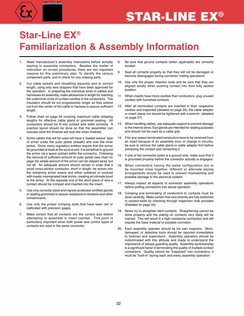
1. Read manufacturer’s assembly instructions before actuallystarting to assemble connectors. Besides the matter ofinstruction on correct procedures, there are two importantreasons for this preliminary step: To identify the variouscomponentparts,andtocheckforanymissingparts.
2. Cut cable jackets and sheathing squarely and to correctlength,usingonlywirestrippersthathavebeenapprovedfortheoperation.Inpreparingtheindividualwiresincablesandharnessesforassembly,makeallowancesinlengthforreachingtheoutermostcircleofcontactcavitiesintheconductors.Theinsulationshouldbecutprogressivelylongerastheyextendout from the center of the cable or harness to assure sufficient length.
3. Followchartonpage34coveringmaximumcablestrippinglengths for effective cable gland or grommet sealing. Allconductors should be fit into contact wire wells correctly. A practice layout should be done so that the assembler canoversee what the finished will look like when finished.
4. Somecablesthatwillbeusedwillhavea‘basketweave’typeofarmorunder theouter jacket (sheath)andover the innerjacket.Sincemanyregulatoryentitiesrequirethatthearmorbe grounded at least at the source end, it is beneficial to ground thearmorviaasparecontactwithintheconnector.Followingthe removal of sufficient amount of outer jacket (see chart on page34)ampleamountofthearmorcanbeclippedaway,butnotall. Anadequateamountshould remain inorder thatasmallcross-sectionconductor,shortinlength,bewovenintothe remainingarmorweaveandeither solderedor coveredwithmasticimpregnatedheatshrink,creatinganintimatebondtothearmor.Attheoppositeendoftheshortpieceofwireacontactshouldbecrimpedandinsertedintotheinsert.
5. Use only correctly sized and ingress protected certified glands orsealinggrommetstoassureresistancetomoistureandothercontaminants.
6. Use only the proper crimping tools that have been set orcalibratedwithprecisiongages.
7. Make certain that all contacts are the correct size beforeattempting to assemble in insert cavities. This point isparticularly importantwhenbothpowerandcontrol typesofcontactsareusedinthesameconnector.
8. Besure thatgroundcontacts (whenapplicable) are correctlylocated.
9. Seatallcontactsproperlysothattheywillnotbedamagedorbecomedisengagedduringconnectormatingoperations
10. Useonly theproper insertion toolsandbesure that theyarealigned axially when pushing contact into their fully seatedposition.
11. Wheninsertshavemorecavitiesthanconductors,plugunusedcavitieswithfurnishedcontacts.
12. After all terminated contacts are inserted in their respectivecavitiesandinspected(detailedonpage34),thecableadapterorinsertclampnutshouldbetightenedwithawrench.(detailedonpage37).
13. Whenhandlingcables,useadequatesupporttopreventdamagetotheinternalwires.Exdglandsareintendedforsealingpurposesandshouldnotbeusedasacablegrip.
14. Ifforanyreasonterminatedconductorshavetoberemovedfromaninsertbecauseofanassemblyerrororchangeincircuitry,be sure to remove the cable gland or cable adapter first before extractingthecontactandreinsertingit.
15. Ifoneoftheconnectorpolesisagroundwire,makesurethatitisgroundedproperlybeforetheconnectoractuallyisengaged.
16. When connectors having the same configuration are tobe mounted close together, different or alternate keyingarrangements should be used to prevent mismatching andpossibledamagetotheelectricalsystem.
17. Always inspectall aspectsof connectorassemblyoperationsbeforeputtingconnectorsintoactualoperation.
18. Crimping and terminating of conductors to contacts must bedonecarefully.Makecertainthatwirestrandsarefullybottomedincontact-wellsbycheckingthroughinspectionholeprovided(Detailedonpage34).
19. Nevertrytostraightenbentcontacts.Straighteningcannotbedone properly and the plating on contacts very likely will bemarred.Thiswillresultinahighresistanceconnectionandwillexposethebasematerialtopossiblecorrosion.
20. Eachassemblyoperatorshouldbehisown inspector. Worn,damaged, or defective tools should be reported immediatelyto foreman and supervisors. Assembly operators should beindoctrinated with this attitude and made to understand theimportanceofalwaysguardingquality.Assemblyworkmanshipis a significant factor in terminating the quality of multiple contact connectors. Qualitycannotbe “inspected” intoconnectors; itmustbe“built-in”duringeachandeveryassemblyoperation.
Star-Line EX®
Familiarization & Assembly Information

AmphenolINDUSTRIAL
STAR-LINE EX®
33Page 4
Star-Line EX®Cable Types
It is the responsibility of the specifier/user to select the appro-priate cable to be used with the EX Star-Line connector sys-tem. The specifier/user should favor the use of cables con-structed with flexible conductors (IEC class 5 or higher/ICEA type H or higher) as well as a flexible armor type (basket weave) if required. Armor systems such as those identified in IEC 92-3 or IEEE455 or UL1309 are recommended. An imper-vious jacket should always be furnished over the armor. IEC/BS cables such as armored with SWA (X), tape(Z), and NEC style cables such as ‘interlocked’ or MC are not recommended with the EX connector system.
The armor system should be grounded at the source point. Periodically the specifier/user should investigate the need for armor grounding (earthing) within the plug or in-line connec-tor itself. In addition to the weaving of the armor grounding conductor, soldering and/or heat shrink and/or strong adhe-sive electrical takes, and/or ‘tension banding’ should be ap-plied on the armor and conductor to insure a permanent bond. The armor grounding wire should be terminated (solder or crimp) to an appropriate sized contact, and inserted into the connector insert.
The armor system should not be confused or associated with shielding which is employed with instrumentation/telecommunication cables. Shielding for pairs/triads have their own individual drain wires which should be terminated onto dedicated contacts. These drain wires should be insulated with heat shrink within the connector body to prevent contact with other drain wires or pair/triad shield faces. The above procedure does not apply to single conductor ca-bles, i.e., 444-1111mcm (150mm-500mm), or multiconductor power or control cables.
Single conductor Cables Periodically single conductor cables will be required in an armored and sheathed construction.
Since there is no armor grounding contact path provided within the connector assembly, a suitable external method must be employed. It is recommended that a small strip of outer jacket be cut away a reasonable distance from the en-trance to the cable gland of the connector. A durable insu-lated conductor with a cross section not smaller than #14awg/4mm should be bonded to the exposed armor. Pro-tective tapes or heat or cold shrink (3M PST) should be applied to protect this bonding point. The opposite end of this grounding conductor should be terminated at the correspond-ing receptacles’ panel via one of the receptacles’ fastening screws or a dedicated grounding lug or bar. In an ‘in-line’ configuration, a mirror image of the above should be used with a simple mating point in close proximity to the connector set.
In summary the specifier/user should be versed in acceptable applications that are allowed by the regulatory/certifying bod-ies having jurisdiction. Periodic inspection of this grounding arrangement should be implemented.
All connectors are furnished with a protective cover. In actual-ity this cover is viewed as a critical part of the connector. The cover is compared to a cover on a flameproof (Eexd) enclo-sure. Absence of the cover voids the Ex certification. The covers should not be viewed as an incidental protection to the external elements, but a required component of a hazardous certified device. When the connectors are plugged together the covers can be screwed into each other to protect the threads from damage. When the connectors are not mated, it is required that the covers be installed and the set screws on the covers be fully driven into the body of the connector. Replacement covers and ‘NYLOK’ set screws are available on request.
SIRA Product Labeling InformationInformation below must be attached to connectors via non-removable label.
AmphenolSidney NY 13838 USA
Star-Line, Size Ref
Work Order Number; Date Code; Facility Code
0518 II 2 GD
IP68-8
Marking for all connectors used in standard(+40°C max.) ambient:
Ex d IIC T6 Gb (Inline Plugs and Receptacles) Ex tb IIIC T80°C Db IP68 (Inline Plugs and Receptacles) Ex de IIC T6 Gb (Panel mount receptacle filled w/ cement) Ex tb IIIC T80°C Db IP68 (Panel mount receptacle filled w/ cement) -20ºC Ò TambÒ +40°C
Marking for inline connectors, used in +55°C max. ambient:(INCREASED TEMP RANGE ONLY ALLOWABLE FOR CONNECTORS (EX-13-3, EX-15-3, EX-17-3) EMPLOYING SUITABLE EX CERTI-FIED GLANDS. THIS MARKING IS NOT APPLICABLE FOR CE-MENTED CONFIGURATIONS)
Ex d IIC T5 Gb (Inline Plugs and Receptacles) Ex tb IIIC T95°C Db IP68 (Inline Plugs and Receptacles) -20ºC Ò Tamb Ò +55°C
Sira 03ATEX1101X & IECEx SIR 10.0064X
“Max volts, Max amp, Current rating per pin”
DO NOT SEPARATE WHEN ENERGIZED

34
STAR-LINE EX®
The following instructions apply to equipment covered by certificate numbers:
Sira 03ATEX1101X & IECEx SIR 10.0064X
The equipment may be used with flammable gases and vapours with apparatus group(s) IIA, IIB, & IIC and with tempe-rature classes T6, T5, T4, T3, T2 & T1.
The equipment is only certified for use in ambient temperatures in the range -20°C to +40oC and should not be used outside this range.
The product complies with the following standards:
Installation shall be carried out by suitably-trained personnel in accordance with the applicable code of practice e.g.
EN/IEC 60079-14 or EN/IEC 61241-14. It is the end user’s responsibility to ensure that the product, as specified and confirmed by the product label, is suitable for it intended application.
Inspection and maintenance of this equipment shall be carried out by suitably trained personnel in accordance with the applicable code of practice e.g. EN/IEC 60079-17 or EN/IEC 61241-17.
Repair of this equipment shall be carried out by suitably trained personnel in accordance with the applicable code of practice e.g. EN/IEC 60079-19.
Components to be incorporated into or used as replacement parts of the equipment shall be fitted by suitably trained personnel, using only components purchased from Amphenol or an Amphenol approved distributor. Any use of non-approved components/suppliers will invalidate the certification for that product.
The certification of this equipment relies upon the following materials used in its construction:
1. Connector Materials:
(Standard Base Material) ASTM B211 or B221 Alloy 6061-T6, Aluminum (<7%Mg, <7%Ti),
(Optional Base Material) ASTM 5640, Alloy 303, Stainless Steel,
(Optional Base Material) ASTM B455, Alloy C38500, Brass.
2. Seal Materials:
Buna Rubber w/ Durometer of 70 SHORE A.
If the equipment is likely to come into contact with aggressive substances, then it is the responsibility of the user to take suitable precautions that prevent it from being adversely affected, thus ensuring that the type of protection provided by the equipment is not compromised. Aggressive substances: e.g. acidic liquids or gases that may attack metals, or solvents that may affect polymeric materi-als.
Suitable precautions: e.g. regular checks as part of routine inspections or establishing from the material’s data sheets that it is resistant to specific chemicals.
EN 60079-0:2006 (IEC 60079-0:2007 5th Ed)
General requirements for electrical apparatus for explo-sive gas atmospheres
EN 60079-1:2007 (IEC 60079-1:2007 6th Ed)
Electrical apparatus for explosive gas atmospheres - Part 1: Flameproof enclosures "d
EN 60079-7:2007 (IEC 60079-7:2006 4th Ed)
Electrical apparatus for explosive gas atmospheres – Part 7: Increased safety "e"
EN 61241-0:2006 (IEC 61241-1:2004 1st Ed + Corr Nov 05)
General requirements for electrical apparatus for use in the presence of combustible dust
EN 61241-1:2004 (IEC 61241-1:2004 1st Ed)
Electrical apparatus for use in the presence of combusti-ble dust. Protection by enclosures “tD”

AmphenolINDUSTRIAL
STAR-LINE EX®
35
SPECIAL CONDITIONS FOR SAFE USE/CONDITIONS OF CERTIFICATIONThe following must be adhered to in full for safety and as to not invalidate product certification.
1. The panel mounted variants may be installed in suitably certified and dimensioned flameproof equipment providing that the certification of this flameproof equipment will allow such installation.
2. The panel mounted variants may be fitted in an increased safety enclosure when the free internal space is filled with epoxy resin and providing the certification of the enclosure will allow such installation. An electric strength test in accordancewithEN60079-7:2007andIEC60079-7:2007Clause7.1willbeperformedoneachunitafterinstal-lationoftheepoxyresin.
3. The Ex-18 range of panel-mounted variants may be installed in a suitably certified and dimensioned flameproof equipment providing that the certification of this flameproof equipment will allow such installation. They have the following dimensionedspigotjointsandaresuitableforGroupIIA,IIBorIIC,dependentupontheassociatedappa-ratusentrydimensions.
1.TheEx-18rangeofreceptaclesshallonlybeusedwherethetemperatureatthepointofentryinserviceontheassociatedenclosureisbetween-20°Cto+70.2°C.
2.TheEx-18rangeconnectordoesnotincorporateanexternalearthfacility.Itistheresponsibilityoftheuserorinstallertoensureadequateearthcontinuitybymeansofguidancegivenwithinthemanufac-turer’sinstallationinstructions.
Shell Size Spigot diameter (mm) Spigot length (mm)
12 39.90/39.85 46 (+/-1)
16 49.90/49.85 46 (+/-1)
20 62.90/62.85 46 (+/-1)
24 74.90/74.85 46 (+/-1)
28 89.90/89.85 46 (+/-1)
Star-Line EX® Connector Mating, Securement and Certification Compliance
TheStarlineEXseriesutilizesatraditionalthreaded(ACME)couplingscheme,withanadditionalenhancement.Thecouplingsleeveispartofanactualassembly.Theassemblyiscomprisedofacouplingsleeve,andtwo(2)grubscrews(setscrews).Theseset screws and their proper implementation, are a requirement of the Certificate of Conformity.
Oncetheconnectorsaremated,andthecouplingnuthasbeentightened,itisarequirementthattheGrubScrewsbothbetightenedusingapropertool(allenkey;suppliedwithconnector).Thispreventsthecouplingnutfrombackingoff,andminimizes“unauthorizeddecoupling”ofthematedconnectorpair.TheGrubScrewswouldhavetobeintentionallyloosened,inorderforthecouplingnuttoberetracted,andtheconnectorsunmated.
WARNING: Compliance with the Certificate of Conformity is satisfied when: 1) the male and female connectors are completely mated, and 2) the coupling sleeve is fully engaged, and 3) the grub screws are fully engaged, and 4) all the above are established before the circuit is energized.
WARNING: When circuits are de-energized, and the connectors, all plugs and receptacles, are un- mated, the respective flameproof blanking caps must be installed, and all grub screws secured. Flame- proof blanking caps are a part of the certification, and their use is required, to maintain flameproof wor- thiness of the connector halves independently, should the circuit be re-energized.

36
STAR-LINE EX®
Star-Line EX®
Assembly & Terminating InstructionsCable Jacket & Wire Stripping
Shell Contact Mod 1 (Solder Contact) Mod 1 (Pressure Contact) Mod 2 & 3 (Crimp Contact) Size Size Strip Lengths (mm) Strip Lengths (mm) Strip Lengths (mm)
AWG(mm) Conductor Jacket Conductor Jacket Conductor Jacket
12 18 (0.75mm) 7.2mm 99.2mm - 90.5mm 11.5mm 90.5mm 16 (1.5mm) 7.2mm 99.2mm - 90.5mm 14.6mm 90.5mm 12 (4.0mm) 8.7mm 99.2mm 17.5mm 90.5mm 15.5mm 90.5mm 10 (6.0mm) 11.9mm 99.2mm 14.3mm 84.1mm 17.1mm 92.1mm
16 18 (0.75mm) 7.2mm 105.5mm - 96.8mm 11.5mm 96.8mm 16 (1.5mm) 7.2mm 105.5mm - 96.8mm 14.6mm 96.8mm 12 (4.0mm) 8.7mm 105.5mm - 96.8mm 15.5mm 96.8mm 10 (6.0mm) 11.9mm 105.5mm - 90.5mm 17.1mm 98.4mm 8 (10.0mm) 15.1mm 105.5mm - 88.9mm 21.0mm 98.4mm 4 (25.0mm) 16.7mm 105.5mm 17.5mm 87.3mm 23.0mm 101.6mm
20 18 (0.75mm) 7.2mm 118.2mm - 109.5mm 11.5mm 109.6mm 16 (1.5mm) 7.2mm 118.2mm - 109.5mm 14.6mm 109.6mm 12 (4.0mm) 8.7mm 118.2mm - 109.5mm 15.5mm 109.6mm 10 (6.0mm) 11.9mm 118.2mm - 103.2mm 17.1mm 111.12mm 8 (10.0mm) 15.1mm 118.2mm - 101.6mm 21.0mm 111.12mm 4 (25.0mm) 16.7mm 118.2mm 17.5mm 101.6mm 23.0mm 113.9mm 1/0 (50.0mm) 18.3mm 118.2mm 19.1mm 98.4mm 31.0mm 115.2mm
535MCM(240mm) 50.0mm 118.2mm - 90.0mm - -
24/C24 18 (0.75mm) 7.2mm 130.9mm - 122.2mm 11.5mm - 16 (1.5mm) 7.2mm 130.9mm - 122.2mm 14.6mm - 12 (4.0mm) 8.7mm 130.9mm - 122.2mm 15.5mm -
10 (6.0mm) 11.9mm 130.9mm - 115.9mm 17.1mm - 8 (10.0mm) 15.1mm 130.9mm - 114.3mm 21.0mm - 4 (25.0mm) 16.7mm 130.9mm 17.5mm 100.0mm 23.0mm - 1/0 (50mm) 18.3mm 130.9mm 19.1mm 117.5mm 31.0mm - 4/0 (120mm) 18.3mm 130.9mm 19.1mm 127.0mm 31.6mm -
535 MCM (240mm) 50.0mm 130.9mm - 90.0mm - -
777 MCM (400mm) 50.0mm 130.9mm - 90.0mm - -
28/C28 18 (0.75mm) 7.2mm 137.3mm - 125.6mm 11.5mm - 16 (1.5mm) 7.2mm 137.3mm - 125.6mm 14.6mm - 12 (4.0mm) 8.7mm 137.3mm - 125.6mm 15.5mm - 10 (6.0mm) 11.9mm 137.3mm - 122.2mm 17.1mm - 8 (10.0mm) 15.1mm 137.3mm - 120.7mm 21.0mm - 4 (25.0mm) 16.7mm 137.3mm 17.5mm 106.4mm 23.0mm - 1/0 (50mm) 18.3mm 137.3mm 19.1mm 123.8mm 31.0mm - 4/0 (120mm) 18.3mm 137.3mm 19.1mm 133.4mm 31.6mm -
350 MCM (185mm)
21.4mm 137.3mm - 130.1mm 33.5mm -

AmphenolINDUSTRIAL
STAR-LINE EX®
37
Thefollowingtablegivesthewiresizesandcord/cabletypestobeusedwiththeStar-lineplugs,receptaclesandcableconnectors.Theplugsandcableconnectorsareintendedforconnectionto3,4or5conductorcords/cables depending on the contact insert configuration.
Thecordsealinggripsrangeforplugsandcordconnectorsis1/8”.Forinstance,ifinsidedia.ofgrommetis3/4”itwillsealandgripacorddia.intherangeof.750dia.max.to.625diamin.Insidediameterofgrommetsareinsixteenthofaninchincrements.
There are two types of contacts used in Mod I style inserts, one is solder, the other is pressure. The pressure contacts apply termination force via a set screw, and require being torque to values provided in the table below:
AmperesRating Conductor TypeofDevice SizeAWG Cord/Cable
20 #14 S,SO30 #12,#10 S,SO60 #6,#4 W100 #0,#1,#2 W200 #3/0,#4/0 W
20amp. 30amp. 40amp. 60amp. 100amp. 200amp. #12contact #10contact #8contact #4contact #1/0contact #4/0contact
Lb-in N/A 15 25 20 50 100N-M N/A 1.7 2.8 2.3 5.7 11.3
NOTE1.Photo“YY”isanexampleofEX-13-3SeriesPlugusingExdgland.
Star-Line EX®
Assembly & Terminating InstructionsElectrical Connectors with MOD I Inserts
A.Prepareendofcablebystrippingjacketandinsulationpertablesshown on previous page. Remove any ridges or grooves by scarfing the edgestoprovideasmoothsurfaceonthecabletoinsuregoodgrommetsealing.Tinconductorstobesolderedtowithin1/16”ofinsulation.Useonly resin flux for all soldering.
B.SlidetheEXglandnut,cablegrip,oranti-frictionwasher,grommetandcableadapter,overthecableintheordernamed.BesuretherightsizeEXglandorgrommethasbeenselectedtoobtainaproperseal.Seephoto“YY”.
C.Solder conductors in contacts, if solder type. TO ENSUREENVIRONMENTALSEALING,ALLCONTACTSMUSTREMAININPLACEEVENIFEVERYONEISNOTBEINGUSED.Thesiliconeinsulationisheatresistant,butreasonablecaremustbeexercisedtopreventunnecessaryheating.ItisrecommendedthataDCinductionsolderingunitbeusedifpossible. Do not use open flame soldering. It is recommended that heat shrink be applied over finished termination point.
D. Support thebarrelassembly inavisehavingsmooth-faced jaws;with female receptacle have flange secured in vice for holding steady. Theplugandreceptaclekeyways/keysaredesignedtowithstandtheassemblytorque.Seephoto“MM”.
E. Applycableadaptororinsulationclampnutbystrapwrench,turningcounterclockwise(lefthandthread)untilhand-tight.APPLYSTRAPWRENCHTOCABLEADAPTERORINSULATIONCLAMPANDTIGHTENUNTILITSHOULDERSFULLYONBARREL. Substantial resistance should be felt by assembler as he rotates adapter on final revolution. See photo“PP”.
F. SlideExglandorgrommetintocableadapterandengageeithercablegrip,orglandwasherandglandnut.DRAW UP TIGHT WITH WRENCH. If mechanical clamp nut is used, tighten clamp screws as final step.
MM PP
YY

38
STAR-LINE EX®
Individualcontactsarecrimpedtotheirrespectiveconductorsoutsideoftheconnectorwhereampleworkingspaceisavailable.Thecrimpingoperationcanbedonebyhandorpoweroperatedtools.Referencepage86ofthiscatalogforpropertoolinformation.
Terminatedcontactsareindividuallyinsertedintotheinsulationwithacontactinsertiontool.Seephoto“JJ”.Contactsmaybeinsertedandremovedwithoutdegradingcontactretentionorenvironmentalcapability.Thefrontrigidportionoftheinsertfunctionstostabilizeandensurepositivealignmentofthecontacts.
Contactcavitiesareclearlynumberedonthefrontandrearinsertfacetofacilitateidentification during assembly, inspection, and maintenance.
Allcontactcavities,whetherusedornot,must be populated in order to maintain certification andproperenvironmentalsealing.
For Electrical Connectors with MOD III Inserts ModIIIconnectorscontaininsulationsthatarefactoryinstalledandlockedintopositionwithanon-removableretainingring.Eachinsulatorassemblycontainsaresilientsealinterposedbetweentworigidplasticinsulators.ModIIIcontactsarerearinsert-ableandrearrelease-ableforquickandeasycircuitchanges.ModIIIcontactsareretainedintheirrespectivecavitiesbymeansofcollapsiblemetalcollets.Themainadvantageofcolletstyleretentionarelowerinsertionforces,eliminatingneedforinsertiontools,andhigherretentionforces.Contactcavitiesareclearlynumberedonthefront and rear insert face to facilitate identification during assembly, inspection, and maintenance. All contact cavities, whetherusedornot,must be populated in order to maintain certification and proper environmental sealing.
All connectors are shipped with the inserts factory installed in the barrel shell, and in the specified key position.
CRIMPING CONTACTS: Contactsarecrimpedoutsideoftheconnectorwithapropertool.Checkthroughtheinspectionholeincontacttomakecertainwiresarefullybottomedinwellbeforecrimping.
1.The panel receptacle is comprised of two basic pieces. The first is the actual panelreceptacleassembly,wherethematingplugenters,andthesecondisthepaneladapter/pottingchamber.
2. Followingtheterminationand/orinsertionofthecontactsintotheirrepresentative cavities, the panel adapter is the firmly tightened all the way until travelceases.
3. Thepottingstepcanthenbecompleted.Afterthepottingcompoundhashardened,thecompletedreceptacleassemblycanbeinstalledintotheenclosure.
4. Thesquarepanelgasketisfurnishedforinstallationontheoutersurfaceoftheenclosure behind the square flange. The sealing washer and brass locknut shouldbefullytightenedwithpropertools.Followingthisstepfourproperlength 10mm screws should be installed into holes in corner of front flange. (Brasslocknutisnotrequiredwhenthreadingreceptacleassemblyintoaflameproof enclosure.
5. Forallincreasedsafetypanelmountreceptacles:InaccordancewithEN50019:2000,Clause7.1,theincreasedsafetyenclosurecertificate must include the use of the device as well as an electric strength test on the finished assembly.
6. The panel mount variant shall be installed in a suitably certified and dimensioned flameproof equipment when it’s certificate allows such installation.
Star-Line EX®
Assembly & Terminating InstructionsElectrical Connectors with MOD II Inserts
JJ
Panel Gasket
Brass LocknutSealing Washer
Panel Mounting a Receptacle

AmphenolINDUSTRIAL
STAR-LINE EX®
39
All cable adapters, other than ones suited for mating with an EX-certified gland, must be filled with encapsulant (potted). The material certified for use in filling this connector line is to be supplied by Amphenol Industrial part number 10-838535.Theuserorinstallershallconsidertheperformanceofthesematerialswithregardtoattackbyaggressivesubstancesthatmaybepresentinthehazardousarea.Thismaterialisatwo-componentcastingsystemwitha1:1volumetricmixratio.Ithaslowexothermicqualities,peakingatonly102°Fduringcure.Thematerialstartstohardeninunder2hoursandfullycuresatroomtemperaturein24.Itcanbequickcuredin2hoursat140°F.Theproductisavailableineasy“mix&dispense”cartridges.Moreinformationisavailablebycontacting:
Amphenol Industrial Operations, Technical Support Phone: (520) 285-5130
Filling DepthsThe Cable Adapter should be filled with the encapsu-lanttothefollowinglevels:
Cable Adapter• In-line cable adapters are filled to within one & three
quarterinches(1¾”)oftheendoftheadapter.Thegoal is to have all the volume filled without interrupting thecablegrommetfromseatingwhenthestrainreliefnutisinstalled.
Panel Adapter (shown above)• Bulkhead adapters should be filled to within
1/16”ofthetop.
Mixing Instructions1. CAUTION:Weargogglesorothereyeprotectionduringall
operations.2. Removethetapebandfromthemid-sectionofthecartridge.3. Squeezecartridgeslightlyinareaoftheremovedtapeband
todeformfoilbarrier.4. Pushthethreadedendofthemixingrodintosmallandfully
threadedintoit’smatingthreadwithinthetube.5. Pushthemixingrodtothebottomofcartridgeandbegin
plungingthemixingrod,thefulllengthofthecartridge,whilerotatingthemixingrodapproximately90°witheachstroke.Mixforthetotalnumberof50strokes.Astrokeisonecompleteinandoutcycle.Onthelaststroke,mixingrodshouldbefullyextendedoutward.
6. Grasp the cartridge firmly at the neck of the tube, and unscrewthemixingrodbyturningcounterclock-wiseapproximately3turns.Removemixingrod.
7. Installnozzleandremovebottomcap.8. Loadtubeintoastandardpainterscaulkgun.9. Potconnectorsinmatedconditiontoassurecontact
alignment.10.PottingnotrequiredwhenusingExd/Exeglandoptionfor
plugsandin-linereceptacles.
Filled With Compound
1-3/4" Empty
Star-Line EX®
Potting Instructions

The following chart illustrates how much potting compound is needed per connector. This is based on fill lengths of 3-7/8”(in-lineadapters)and1-3/4”(Panelmountadapters)andthesmallestallowablecablediameterincludedforeachparticularshell.
ShellSize Approx.Cementusage Approx.Cement ina6”cableadapter* usageinabulkhead adapter* (FluidOunces) (FluidOunces)
12 1.6 .5
16 3.5 1.1
20 6.1 2.1
24 9.0 3.3
28 11.1 4.5
* Note: These volumes are estimated. Necessary volumes may vary depending on conductor count, insulation, and jacket thickness.
RecommendationsItisrecommendedwherepossible,thatwhenmatedsetsofconnectorsarepottedthattheconnectorwiththefemaleinsertbe potted first, allowed to set and then the male be potted while it is mated to the previously potted female connector. This willensurethatthemalecontactswillbeseatedor ‘aimed’properlyatthefemalesocketcontactoppositeit. Themalecontactshaveagivenamountofmovementwhilenotengaged,andifduringinitialpottingproceduresthemalecontactsarepositionedbeyondthismovementrange,theywillnotproperlymakecontactwiththesocketcontact.
Cartridge
Foil Barrier
Plunger
Bottom Cap
Base Compound
Tape Band
Catalyst
Mixing Rod
Star-Line EX®
Potting InstructionsVolume Chart
40
STAR-LINE EX®

41
STAR-LINE®
Plug w/ Mech. Clamp Dead Front Pin (Line side) RIG-10P▲-XX-M-◆ RIG-R10P▲-XX-M-◆ Plug w/ Mech. Clamp Socket Contact (Load Side) RIG-10S▲-XX-M-◆ RIG-R10S▲-XX-M-◆ Cable Receptacle w/ Mech. Clamp Dead Front Pin (Line side) RIG-15P▲-XX-M-◆ RIG-R15P▲-XX-M-◆ Cable Receptacle w/ Mech. Clamp Socket Contact (Load Side) RIG-15S▲-XX-M-◆ RIG-R15S▲-XX-M-◆ Fixed CableReceptacle w/ Mech. Clamp Dead Front Pin (Line side) RIG-17P▲-XX-M-◆ RIG-R17P▲-XX-M-◆ Fixed Cable Receptacle w/ Mech. Clamp Socket Contact (Load Side) RIG-17S▲-XX-M-◆ RIG-R17S▲-XX-M-◆ Panel Mount Receptacle (Bus Bar) Dead Front Pin (Line side) RIG-17PR-◆ RIG-R17PR-◆ Panel Mount Receptacle (Bus Bar) Socket Contact (Load Side) RIG-17SR-◆ RIG-R17SR-◆ Panel Mount Receptacle (Direct Cable Entry) Dead Front Pin (Line side) RIG-17PN-◆ RIG-R17PN-◆ Panel Mount Receptacle (Direct Cable Entry) Socket Contact (Load Side) RIG-17SN-◆ RIG-R17SN-◆
Rig-Power® Connectors (1000v AC/DC)
RIG-Power Grommet Selection Guide (XX)
* ▲ Select Cable Size. See Cable Size & Amperage Guide below. XX - Select Cable Diameter Code #. See Grommet Selection Guide below.
M designates Mechanical Clamp (For basketweave grip substitute K for M). ◆ Select standard color code from Color Code options below. Use Crimp Tool: T&B #TBM15
Connector Standard RIG-Radsok® Style Insert Gender Part Number* Part Number*
Standard Color Code Blue Orange Yellow Brown Red White Black Green PartNumberSuffix◆ -BL -OR -Y -BR -R -W -BK -G
Current Type DC AC
NOTE: Radsok® version not backward compatible with original contact design
1.000-1.125 18 1.125-1.250 20 1.250-1.375 22 1.375-1.500 24 1.500-1.625 26 1.625-1.750 28 1.750-1.875 30
Cable Diameter Code No. (XX)
Cable Size & AmperageSelection Guide (p)
Color Code Options (t)
Single Pole Power
NOTE: It is the responsibility of the user to ensure other components of their system have equal/greater amperage carrying capacity.
AmphenolINDUSTRIAL
2 = 313 kcmil 625 925 76 3 = 373 kcmil 700 1000 87 4 = 444 kcmil 800 1200 107 5 = 535 kcmil 900 1350 107 6 = 646 kcmil 1000 1500 107 7 = 777 kcmil 1135 1500 115
Standard RIG-Radsok® TBM 15 Cable Size Amperage Amperage Die Code No.

8.703
PLUG RIG-10X -XX-M
PANEL MOUNT RECEPTACLERIG-17X
8.734
.297 DIA. 4 HOLES
2.531 SQ.
3.250 SQ.
NOTE: See page 20, shell size C24 for full mounting dimensions.
RIG-R17SR-RRIG-Power® Receptacle w/Radsok ®
Busbar Socket (Color Code Red)
RIG-R10P7-22-M-RRIG-Power® Plug w/Radsok® Pin (Color Code Red)
EX-13-3-D2-C24-R386PNStarLine EX Plug w/Radsok® Pin
Mated Pair Starline EX Rig-Power w/Radsok®
EX-17-1-C24-R386SRStarline EX Receptacle w/Radsok® Socket
4242
Single Pole Power

PANEL BOARD SOCKETTMPC-41777-L
DIA. MOUNTING HOLE1.066 DIA. OVER KNURL1.062
1.052
2.250
3.5006.000
.547 MIN.PANEL THICKNESS
CLEVIS PIN
5.969
2.750 .547 MIN. PANEL THICKNESS
.750 2.250
1.066 DIA. OVER KNURLMOUNTING HOLE DIA.
1.0621.052
PANEL BOARD SOCKETP-500126-BS
1.875
3.6251.375 BOOT
1.250 D.955 D
PIN
.750 D2.656 D
6.813
PIN P-500126-P
1.875
3.6251.375 BOOT
1.375 D1.062 D
PIN
.750 D2.656 D
6.813
PIN PD-501-L
Wire Type of Part Boot Part # Cable Ampacity Size Termination Gender Number (See Color Code) Sealing Range
P-500TM / PD-501 POWER Connectors
900* – Stud Socket P-500126-BS-◆ – – 900* 535MCM Solder Pin PD-501-L TMPC-10-◆ 1.125 - 1.500 900* 535MCM Crimp Pin P-500126-P TMPC-10-◆ 1.125 - 1.500 325 313MCM Solder Pin PD-501-S TMPC-10-◆ 1.125 - 1.500
1.875
3.6251.375 BOOT
1.187 D.875 D
PIN
.750 D2.656 D
6.813
PIN PD-501-S
Note: Connectors are rated at 1000 Volts AC/DC when mounted on 5" centers.Copper alloy, silver plated contacts for maximum conductivity.Crimp tool required for P-500126-P is Thomas & Betts hex crimp using Tool # TBM15 &
die catalog #15505 or BURNDY “YA”* When used with 125° C rated cable.
With Standard With Radsok Contacts Contacts Cable Type of Part Current Part Current Wire Boot Sealing Gender Termination Number Range Number Range Size Part No. Range
Note: TMPC Connectors are rated at 1000 Volts AC/DC when mounted on 5" centers.Material is copper alloy, silver plated for maximum conductivity and corrosion resistance.Recommended crimping tools are as follows: Anderson (Square D) Versa Crimp VC8 (four indent).
TMPCTM Connectors
.656 DIA. 2 HOLES
6.000
1.750
MOTOR BUS BAR MOUNT�SOCKET TMPC-41777-24L�
Single Pole Power Connectors
COLOR CODE DOT
4-1/16 REF.
1-1/8 DIA.
Socket 7/8" Stud/Panel Board TMPC-41777-L-◆ 900-1135 amps TMPC-41777-RL-◆ 1500 N/A N/A N/A Socket 2 Hole Bus Bar TMPC-41777-24L 900-1135 amps TMPC-41777-R24L 1500 N/A N/A N/A Pin Crimp TMPC-40535-L 900 amps TMPC-40535-RL 1500 444-535 kcmil TMPC-10-◆ 1.125-1.500 Pin Crimp TMPC-40777-L 900-1135 amps TMPC-40777-RL 1500 646-777 kcmil TMPC-10-◆ 1.125-1.500
TMPC-10-R
43
Single Pole Power AmphenolINDUSTRIAL

AmphenolINDUSTRIAL
44
STAR-LINE® AmphenolINDUSTRIAL
TMPC POWER MOUNT
Amphenol® TMPC POWER MOUNT Flange Mounted Traction Motor Power Connector series featuring RADSOK® Contacts.
Amphenol Industrial Operations introduces the addition of our “NEW” TMPC Power Mount flange mounted connector series. The New TMPC Power Mount series is an addition to our time tested TMPC Single Pin power connector line. The TMPC Power Mount incorporates our existing TMPC connectors with RADSOK® contacts into our new thermoplastic molded receptacle flange.
Available in color codes per the NEC AC/DC Electrical requirements, the TMPC Power Mount series is designed to work with current IEEE Type P drilling cables (sizes range from 313 MCM through 777 MCM). The RADSOK® contacts allow for higher amperages and reduced insertion/removal forces when compared to similar products in the market.
Features & Benefits: • RADSOK contact provide increased
amperages than competition • Contacts rated at 1500 amp for 777 MCM
cables • Contacts machined from high grade
aluminum to offer longer life, more mating cycles
• Lower insertion/removal forces is a by-product of our RADSOK contacts
• Molded flange base mounts directly to Stainless or Aluminum panels, thus eliminating the need for added secondary mounting fixtures
• Color coded mounting bases and cable side boots available to help prevent cross mating, while allowing easier electrical phase identification
• Connector series comes complete with molded Hypalon caps and insulation boots
• Patent Pending
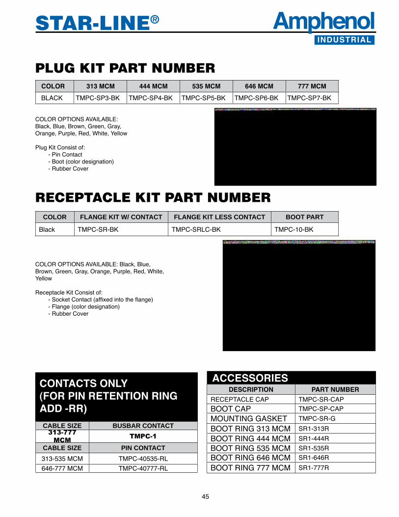
AmphenolINDUSTRIAL
AmphenolINDUSTRIAL
45
STAR-LINE®
PLUG KIT PART NUMBERCOLOR 313 MCM 444 MCM 535 MCM 646 MCM 777 MCMBLACK TMPC-SP3-BK TMPC-SP4-BK TMPC-SP5-BK TMPC-SP6-BK TMPC-SP7-BK
COLOR OPTIONS AVAILABLE: Black, Blue, Brown, Green, Gray, Orange, Purple, Red, White, Yellow
Plug Kit Consist of:- Pin Contact- Boot (color designation)- Rubber Cover
RECEPTACLE KIT PART NUMBERCOLOR FLANGE KIT W/ CONTACT FLANGE KIT LESS CONTACT BOOT PART
Black TMPC-SR-BK TMPC-SRLC-BK TMPC-10-BK
COLOR OPTIONS AVAILABLE: Black, Blue, Brown, Green, Gray, Orange, Purple, Red, White, Yellow
Receptacle Kit Consist of:-SocketContact(affixedintotheflange)- Flange (color designation)- Rubber Cover
CABLE SIZE BUSBAR CONTACT313-777
MCM TMPC-1
CABLE SIZE PIN CONTACT313-535 MCM TMPC-40535-RL646-777 MCM TMPC-40777-RL
CONTACTS ONLY (FOR PIN RETENTION RING ADD -RR)
DESCRIPTION PART NUMBERRECEPTACLE CAP TMPC-SR-CAPBOOT CAP TMPC-SP-CAPMOUNTING GASKET TMPC-SR-GBOOT RING 313 MCM SR1-313RBOOT RING 444 MCM SR1-444RBOOT RING 535 MCM SR1-535RBOOT RING 646 MCM SR1-646RBOOT RING 777 MCM SR1-777R
ACCESSORIES

AmphenolINDUSTRIAL
46
STAR-LINE® AmphenolINDUSTRIAL
Insert ConfigurationListingFor Amphenol®/ Pyle® Star-Line, Star-Lok and Star-Line EX Connectors
IntroductionTheAmphenol/PyleStar-LineInsertConfigurationListingisissuedprimarilytoidentifyvariouscontactinsertarrangements.Fortheengineer,itprovidesvisualselectionoftheinsertconfigurationneededtosatisfyhisrequirements.For the end user, the list provides general information useful in the termination of plugs and receptacles. To aid the reader, theinsertconfigurationsarepresentedinnumericalorder,basedonthenumberofcontactsineach.
The male insert illustration shown left (and those on the following pages) is shown as it appears when viewed from the front. Contacts are shown by both physical positionwithintheconfigurationandbycontactnumber.The contact number corresponds to the contact position shown on the rear face of the insert illustrated as well as to both the front and rear faces of the mating insert. The symbol used to show contact location is indicative of contact size. For example, the contact symbol in this illustration represents a #8 contact. An explanation of contact symbols is presented on each page of the listing. Each drawing also provides data on normal and alternate key positions. Drawings are reduced from actualsizeoftheinsertconfiguration.
NOTE: Alternate keying or insert polarization is intended to resist improper intermating of plugs and receptacles of like shell sizes and like insert arrangements.
Contact Insert Ordering
Plug and receptacle contact inserts are selected according to requirements for Service Voltage Rating, Number of Contacts, Wire Size and Ampere Rating.
Mod I and II inserts may be purchased separately for assembly into the basic barrel. The Catalog Number for each is shown on the chart accompanying each drawing. Pin or socket inserts are interchangeable in male and female barrels.
Mod III inserts, as a unit, cannot be purchased separately because contact inserts are factory assembled to, and sealed in,thebasicbarrel.TheDashNumbergivenwitheachModIllconfigurationmustbeshownasasuffixtothebasicbarrelCatalog Number to identify the insert desired.
Arrangements are available with high amperage RADSOK®contactsspecificallydesignedforStar-Lineinserts.Thesearedesignated with an ‘R’ in the part number. For example: ZP-C28-R42PR would designate an insert with size 4/0 RADSOK pin contacts. ZP-C28-R42SR would designate an insert with size 4/0 socket contacts.

AmphenolINDUSTRIAL
AmphenolINDUSTRIAL
47
STAR-LINE®
Three Classifications of Ampere RatingsMS Ampere Ratings: (MIL-C-39029)Based on the combination of the following:The amount of current which an individual pin and socket contact may carry is a function of contact material and design efficiencyofthepinandsocketsystemaswellastheabilityoftheprimaryconductorinsulationtoresisttemperaturerisesdue to inherent copper losses and bundling factors.Total current carrying capacity of the connector is a function of the insert temperature which is rated at 225° F (107° C) for continuous operation. The total operating temperature is the summation of the ambient temperature plus the temperature rise resulting from the thermal losses of each contact.MIL-W-5088specificationsmaybeusedasageneralreferenceonthesubjectinasmuchaspertinentcablederatingdatais included.
N.E.C. Non-Circuit-Breaking or Disconnect Ampere RatingsThe non-interrupting current ratings, shown in the table, are based on the temperature of the contacts being within the rangespecifiedbyUnderwriter’sLaboratories,Inc.whenwiresizesareselectedinaccordancewiththeNational Electrical Code.When multiple conductors are used, the load factor and temperature rise based on ambient and total insert temperature must be taken into consideration..
Service Voltage RatingsThe voltage to which contact inserts are limited is a function of the dielectric separation between adjacentcontactsandbetweencontacts and shell.The voltage rating is designated by a service voltage rating letter which is shown in the service voltage rating table with each contact configurationlisting.
ELECTRICAL Ratings
NOTE: The N.E.C. circuit breaking and non-circuit breaking ratings are based on test results of contacts and connectors. ConsulttheN.E.C.whenselectingwire/cableforspecificapplications. Under certain conditions, a wire size may be rated higher or lower than the table indicates for a given contact size.
† Measurements made at extreme ends of mated contacts with probe touching contact and wire (MIL-5015 specifications).
** Based on temperature rise (National Electrical Code Requirement).
*** Based on Arcing Control (National Electrical Code Requirement).
MIlitary N.E.C. Ratings Ratings MIL-5015 Non- Circuit Over Specifications Circuit Breaking Surface Thru-Air Non-Circuit Distance Spacing Breaking Inches Inches Service D.C. A.C. D.C. A.C. Nominal Nominal Voltage Volts Volts RMS RMS RMS RMS
Instrument 250 200 – – 1/16 – A 700 500 250 240 1/8 1/16 D 1250 900 600 600 3/16 1/8 E 1750 1250 600 600 1/4 3/16 B 2450 1750 600 600 5/16 1/4 C 4200 3000 600 600 1 5/16
Non-Circuit Breaking † MV Drop Contact Ampere Rating Size AWG/ MS N.E.C. Solder Crimp MCM *** Contacts Contacts
#18 – 9 22 30 #16 13 16 21 29 #12 23 30 20 27 #10 33 40 16 26 # 8 46 50 12 23 # 4 80 90 10 22 #1/0 150 155 10 22 #4/0 225 225 8 22 350 MCM – 325 8 – 500 MCM – 750 – 30 535 MCM – 839 – – 646 MCM – 937 – – 777 MCM – 1048 – –
For Amphenol Star-Line product insert de-rating information per the National Electric Code, please consult the Amphenol Industrial website, www.amphenol-industrial.com. Chart is located under LItErAturE tab.

AmphenolINDUSTRIAL
48
STAR-LINE® AmphenolINDUSTRIAL
Spare/Replacement Contacts for MOD II and MOD III InsertsContacts are machined copper alloy ranging in size (AWG) from #18 to 500 MCM. Standard line contacts are silver plated but can also be furnished with gold over silver, gold over nickel, and other combinations of plating systems available upon request. Pin contacts are of blended geometry to provide extra strength and protection against damage. Socket contacts are the closed entry type. Contacts for MOD I inserts are not listed because these inserts are factory assembled and damage may be done to the resilient centerinsulationifcontactsareinsertedorremovedbyinexperiencedpersonnelinthefield.
18 Pin ZP-4018-36L 18 Socket ZP-4118-36L 16 Pin ZP-4016-36L ZP-4016-37L 16 Socket ZP-4116-36L 12 Pin ZP-4012-36L ZP-4012-37L3 12 Socket ZP-4112-36L 10 Pin ZP-4010-36L ZP-4010-37L2 10 Socket ZP-4110-36L 8 Pin ZP-4008-66L 8 Socket ZP-4108-66L 4 Pin ZP-4004-66L ZP-4804-66L 4 Socket ZP-4104-66L ZP-4904-66L 1/0 Pin ZP-4000-66LB ZP-4800-66LKB 1/0 Socket ZP-4100-66L ZP-4900-66LK 4/0 Pin ZP-4041-76LB 4/0 Socket ZP-4141-76L 500 MCM Pin P-206053-CP 500 MCM Socket P-206053-CS 535 MCM Pin RIG-C24-535PN 535 MCM Socket RIG-C24-535SN 646-777 MCM Pin RIG-C24-386PN 646-777 MCM Socket RIG-C24-386SN
“W” length represents standard insert length for sizes 12, 16, 20 24 and 28. “C” length represents longer insert length for sizes C20, C24 and C28. Contacts in “C” length inserts are 1/2” longer than standard. Ground contacts are 1/8” longer than standard. Ground clips are part of inserts. “C’ length ground contacts are 1/8” longer than “C” length line contacts.
MOD II Size “W” “C” “W” Polarizing Polarizing Awg/MCM Length Length Ground Standard “C”
For Amphenol Star-Line product insert de-rating information per the National Electric Code, please consult the Amphenol Industrial website, www.amphenol-industrial.com. Chart is located under LITERATURE tab.

AmphenolINDUSTRIAL
AmphenolINDUSTRIAL
49
STAR-LINE®
Contact WIRE WELL DIMENSIONS Size Solder Mod I Crimp* Mod II Crimp* Mod III AWG (mm) Diameter Depth Diameter Depth Diameter Depth #18 (0.75) .060” (1.52) 13/64” (5.15) .059” (1.49) 3/8” (9.52) .058” (1.47) 3/8” (9.52) #16 (1.5) .079” (2.00) 13/64” (5.15) .079” (2.00) 1/2” (12.70) .079” (2.00) 1/2” (12.70) #12 (4.0) .117” (2.97) 17/64” (6.47) .113” (2.87) 17/32” (6.74) .113” (2.87) 17/32” (13.49) #10 (6.0) .142” (3.61) 25/64” (9.92) .142” (3.60) 19/32” (15.09) .142” (3.60) 19/32” (15.08) #8 (10.0) .210” (5.33) 33/64” (9.12) .189” (4.80) 3/4” (19.05) .188” (4.77) 3/4” (19.05) #4 (25.0) .333” (8.45) 37/64” (14.63) .289” (7.34) 53/64” (21.03) .278” (7.06) 53/64” (21.03) 1/0 (50.0) .470” (11.94) 41/64” (16.27) .445” (11.30) 1-1/8” (28.58) .455” (11.56) 15/16” (23.81) 4/0 (120.00) .656” (16.7) 57/64” (22.62) .656” (16.7) 15/16” (23.81) 350MCM (185.00) .798” (20.27) 1-1/8” (28.58) 500 MCM (240.00) 1.00” (25.40) 1-3/8” (34.93)
Termination DataAmphenol – Pyle Connectors Corporation’s tools for contact crimping, insertion and removal are required for terminating and assembling contacts.
Contact Dimensions
Torque Data forPressure Contacts
MOD I Contact/Conductor Torque Req. Retention Force Size/Awg (mm) In./Lbs. (N•m) Lbs. (N) 4/0 (120.00) 100 (11.3) 4/0 450 (2001.7) 3/0 350 (1556.9) 2/0 300 (1334.5) 1/0 (50.0) 50 (5.7) 1/0 250 (1112.0) #1 200 (889.6) #2 180 (800.7)
#4 (25.0) 20 (2.3) #4 140 (622.8) #6 100 (444.8) #8 90 (400.3)
#8 (10.0) 25 (2.8) #8 75 (333.6)
#10 (6.0) 15 (1.7) #10 80 (355.9) #12 70 (311.4) #14 60 (266.9)
* Crimp contacts have inspection hole.
Crimp Data Conductor Crimp Retention Contact Wire Size (AWG) Min. Force Size Crimped Lbs. (N)
#18 38 (169.0) #18 (0.75) #20 19 (84.5) #22 15 (66.7) #16 50 (222.4) #16 (1.5) #18 38 (169.0) #20 19 (84.5) #12 110 (489.3) #12 (4.0) #14 70 (311.4) #16 50 (222.4) #10 180** (800.7) #10 (6.0) #12 110 (489.3) #14 70 (311.4) #8 225 (1000) #8 (10.0) to #10 180 (800) #4 400 (1779) #4 (25.0) to #6 300 (1334) #2 550 (2447) 1/0 (50.0) to 1/0 700 (3114) 4/0 875 (3892) 4/0 (120.00) 3/0 825 (3670) 2/0 750 (3336) 500(240.00) 500 MCM 2500 (11120) 535 Recommend using Thomas & Betts 646 TBM 15 crimp tool with appropriate 777 sized dies.
** Stranded wire


Insert MOD MOD MOD Radsok Total 18 16 12 10 8 4 1/04/0313MCM350MCM373MCM444MCM 535MCM 646-777 Page Arrangement I II III Contacts Number (0.75) (1.5) (4.0) (6.0) (10.0) (250) (50.0) (120.0) (185.0) (240.0)(300-400)No. Number ofContacts
Insert Configuration IndexFor drawings and further information of insert arrangements listed see the referenced page numbers. Arrangements with RADSOK contacts are designated with an ‘R’ in front of the dash number in the part number. For availability of other arrangements, consult Amphenol Industrial Operations.
RIG-C24-386 X 1 1 54 RIG-C24-R386 X X 1 1 54 RIG-C24-535 X 1 1 54 RIG-C24-R535 X X 1 1 54RIG-C24-313X1 54 RIG-C24-R313XX1 54RIG-C24-373X1 54 RIG-C24-R373XX1 54RIG-C24-444X1 54 RIG-C24-R444XX1 54 ZP-12-310 X(G) X 7 7 64 ZP-12-14 X 4 4 56 ZP-12-314 X 4 4 56 ZP-12-316 X 4 4 56 ZP-12-22 X(G) 4 4 56 ZP-12-322 X(G) 4 4 56 ZP-12-323 X 17 17 70 ZP-12-24 X 5 5 59 ZP-12-324 X X 5 5 59 ZP-12-326 X 5 3 2 61 ZP-12-27 X 3 3 55 ZP-12-327 X X 3 3 55 ZP-12-330 X(G) X 3 3 55 ZP-12-33 X 4 4 56 ZP-12-333 X 4 4 56 ZP-12-334 X(G) 10 10 67 ZP-12-348 X 7 7 64 ZP-12-53 X(G) 5 5 59 ZP-12-653 X(G) 5 5 59 ZP-12-354 X X 7 7 65 ZP-12-355 X 10 10 67 ZP-12-56 X(G) 3 3 55 ZP-C-16-341X1 54 ZP-16-312 X(G) X 19 19 71 ZP-16-16 X 5 5 59 ZP-16-316 X 5 5 59 ZP-16-321 X 37 37 74 ZP-16-22 X 4 4 57 ZP-16-322 X 4 4 57 ZP-16-324 X 18 16 2 70 ZP-16-325 X 16 16 69 ZP-16-28 X 4 4 57 ZP-16-328 X 4 4 57 ZP-16-29 X 9 8 1 66 ZP-16-333 X 61 61 79 ZP-16-335 X 27 24 3 73 ZP-16-37 X 26 18 4 4 73 ZP-16-38 X(G) 4 4 57 ZP-16-638 X(G) 4 4 57 ZP-16-640 X 55 55 77 ZP-16-344 X 21 11 10 72 ZP-16-346 X 9 6 3 66 ZP-16-349 X 14 12 2 68 ZP-16-355 X 19 19 71
(G) depicts arrangement with grounded contact
11
1
1
1
1
AmphenolINDUSTRIAL
51
STAR-LINE®

AmphenolINDUSTRIAL
52
STAR-LINE® AmphenolINDUSTRIAL
Insert MOD MOD MOD Radsok Total 18 16 12 10 8 4 1/0 4/0 350MCM 500MCM 646-777 Page Arrangement I II III Contacts Number (0.75) (1.5) (4.0) (6.0) (10.0) (250) (50.0) (120.0) (185.0) (240.0) (300-400) No. Number ofContacts
Insert Configuration IndexFor drawings and further information of insert arrangements listed see the referenced page numbers. Arrangements with RADSOK contacts are designated with an ‘R’ in front of the dash number in the part number. For availability of other arrangements, consult Amphenol Industrial Operations.
(G) depicts arrangement with grounded contact
ZP-16-70 X 3 3 55 ZP-16-371 X 46 45 45 1 76
ZP-16-373 X(G) 27 24 3 73
ZP-16-74 X(G) 3 3 55
ZP-16-75 X(G) 5 5 59
ZP-16-376 X(G) 10 6 4 67
ZP-16-377 X X 19 19 70
ZP-16-378 X(G) 7 7 65
ZP-16-381 X 10 6 4 67
ZP-20-313 X 68 68 79
ZP-20-323 X 38 35 3 75
ZP-20-329 X 64 62 2 79
ZP-20-331 X 22 20 2 73
ZP-20-32 X 20 20 72
ZP-20-332 X X 20 20 72
ZP-20-334 X 20 16 4 72
ZP-20-35 X 60 60 78
ZP-20-38 X(G) 5 5 60
ZP-C20-40 X(G) 4 4 57
ZP-C20-640 X(G) 4 4 57
ZP-C20-42 X 4 4 58
ZP-20-43 X(G) 6 2 4 62&82
ZP-20-643 X(G) 6 2 4 62
ZP-20-344 X 81 70 11 80
ZP-20-345 X 90 90 80
ZP-20-46 X 6 4 2 62
ZP-20-646 X 6 4 2 62
ZP-20-48 X 6 3 3 62
ZP-20-648 X 6 3 3 62
ZP-20-49 X 5 3 2 61
ZP-20-649 X 5 3 2 61
ZP-20-350 X(G) X 37 37 75
ZP-20-354 X 47 45 2 76
ZP-20-55 X 10 8 2 68
ZP-20-358 X 16 16 70
ZP-20-359 X 7 7 65
ZP-20-673 X 50 46 4 77
ZP-20-374 X 27 25 2 74
ZP-20-375 X 12 12 68
ZP-20-376 X X 19 19 71
ZP-C20-379 X 1 1 54
ZP-20-84 X 5 5 60
ZP-20-384 X 5 5 60
ZP-20-386 X X 37 37 74
ZP-20-387 X(G) X 20 20 72
ZP-20-388 X(G) 19 19 71
ZP-24-313 X 100 100 81
ZP-C24-26 X(G) 4 4 58

AmphenolINDUSTRIAL
AmphenolINDUSTRIAL
53
STAR-LINE®
Insert MOD MOD MOD Radsok Total 18 16 12 10 8 4 1/0 4/0 350MCM 500MCM 646-777 Page Arrangement I II III Contacts Number (0.75) (1.5) (4.0) (6.0) (10.0) (250) (50.0) (120.0) (185.0) (240.0) (300-400) No. Number ofContacts
Insert Configuration IndexFor drawings and further information of insert arrangements listed see the referenced page numbers. Arrangements with RADSOK contacts are designated with an ‘R’ in front of the dash number in the part number. For availability of other arrangements, consult Amphenol Industrial Operations.
(G) depicts arrangement with grounded contact
ZP-24-331 X 60 53 7 78
ZP-C24-36 X 37 35 2 75
ZP-C24-38 X 4 4 58
ZP-24-40 X 15 10 5 69
ZP-C24-47 X 15 10 5 69
ZP-C24-48 X 5 2 3 61
ZP-C24-49 X(G) 5 5 60
ZP-24-352 X(G) X 58 58 78
ZP-C24-353 X 8 4 4 65
ZP-24-354 X 75 61 11 3 80
ZP-24-362 X 62 62 79
ZP-24-371 X 37 37 75
ZP-C24-72 X 6 3 3 63
ZP-C24-79 X 5 5 60
ZP-C24-680 X(G) 10 6 4 68
ZP-C24-81 X(G) 15 10 5 69
ZP-24-83 X 4 4 58
ZP-24-84 X 58 58 77
ZP-24-384 X X 58 58 77
ZP-24-385 X 100 100 81
ZP-24-388 X 72 72 80
ZP-24-389 X 60 60 78
ZP-28-314 X 100 83 17 81
ZP-C28-15 X 47 43 3 1 76
ZP-C28-18 X 6 2 4 63&82
ZP-C28-R18 X 6 2 4 82
ZP-C28-21 X 8 4 4 66
ZP-28-322 X 143 143 81
ZP-C28-23 X(G) 5 5 61
ZP-28-324 X 55 41 5 3 6 77
ZP-C28-327 X 6 6 63
ZP-C28-328 X 29 23 2 4 74
ZP-28-339 X X 42 42 76
ZP-C28-42 X(G) 6 2 4 64&83
ZP-C28-43 X(G) 8 4 4 66
ZP-C28-R44 X X 7 1 3 4 64&83
ZPC28-R44 83
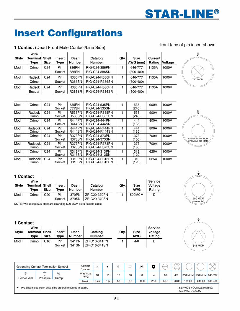
AmphenolINDUSTRIAL
54
STAR-LINE® AmphenolINDUSTRIAL
Insert Configurations1 Contact (Dead Front Male Contact/Line Side) Wire Style Terminal Shell Insert Dash Catalog Qty. Size Current Type Size Type Number Number AWG (mm) Rating Voltage Mod II Crimp C24 Pin 386PN RIG-C24-386PN 1 646-777 1135A 1000V Socket 386SN RIG-C24-386SN (300-400) Mod II Radsok C24 Pin R386PN RIG-C24-R386PN 1 646-777 1135A 1000V Crimp Socket R386SN RIG-C24-R386SN (300-400)
front face of pin insert shown
N
777 MCM
Mod II Radsok C24 Pin R386PR RIG-C24-R386PR 1 646-777 1135A 1000V Busbar Socket R386SR RIG-C24-R386SR (300-400)
Mod II Crimp C24 Pin 535PN RIG-C24-535PN 1 535 900A 1000V Socket 535SN RIG-C24-535SN (240) Mod II Radsok C24 Pin R535PN RIG-C24-R535PN 1 535 900A 1000V Crimp Socket R535SN RIG-C24-R535SN (240)Mod II Crimp C24 Pin R444PN RIG-C24-444PN 1 444 800A 1000V Socket R444SN RIG-C24-444SN (185)Mod II Radsock C24 Pin R444PN RIG-C24-R444PN 1 444 800A 1000V Crimp Socket R444SN RIG-C24-R444SN (185)Mod II Crimp C24 Pin R373PN RIG-C24-373PN 1 373 700A 1000V Socket R373SN RIG-C24-373SN (150)Mod II Radsock C24 Pin R373PN RIG-C24-R373PN 1 373 700A 1000V Crimp Socket R373SN RIG-C24-R373SN (150)Mod II Crimp C24 Pin R313PN RIG-C24-313PN 1 313 625A 1000V Socket R313SN RIG-C24-313SN (120)Mod II Radsock C24 Pin R313PN RIG-C24-R313PN 1 313 625A 1000V Crimp Socket R313SN RIG-C24-R313SN (120)
N
535 MCM, 444 MCM373 MCM, 313 MCM
1 Contact Wire Service Style Terminal Shell Insert Dash Catalog Qty. Size Voltage Type Size Type Number Number AWG Rating Mod II Crimp C20 Pin 379PN ZP-C20-379PN 1 500MCM D Socket 379SN ZP-C20-379SN
N
NOTE: Will accept 535 standard stranding 500 MCM extra flexible cable.
Contact Symbols
Wire Size AWG
18 16 12 10 8 4 1/0 4/0 350 MCM 500 MCM 646-777
Metric 0.75 1.5 4.0 6.0 10.0 25.0 50.0 120.00 185.00 240.00 300-400
Grounding Contact Termination Symbol
Solder Well Pressure Crimp
★ Pre-assembled insert should be ordered mounted in barrel. SERVICE VOLTAGE RATING A = 240V, D = 600V
1 Contact Wire Service Style Terminal Shell Insert Dash Catalog Qty. Size Voltage Type Size Type Number Number AWG Rating Mod II Crimp C16 Pin 341PN ZP-C16-341PN 1 4/0 D Socket 341SN ZP-C16-341SN
N
341 MCM

AmphenolINDUSTRIAL
AmphenolINDUSTRIAL
55
STAR-LINE®
3 Contacts Wire Service Style Terminal Shell Insert Dash Catalog Qty. Size Voltage Type Size Type Number Number AWG Rating Mod I Solder 12 Pin 27P ZP-12-27P 3 12 D Socket 27S ZP-12-27SMod II Radsok 12 Pin 327PN ZP-12-327PN Crimp Socket 327SN ZP-12-327SN
N
2
3
101
36o
0272o
03108o
04
144o05
180oUL® �
Insert Configurations
3 Contacts Wire Service Style Terminal Shell Insert Dash Catalog Qty. Size Voltage Type Size Type Number Number AWG Rating Mod II Crimp 12 Pin 330PN ZP-12-330PN 3 12 D Radsok Socket 330SN ZP-12-330SN
front face of pin insert shown
3 Contacts Wire Service Style Terminal Shell Insert Dash Catalog Qty. Size Voltage Type Size Type Number Number AWG Rating Mod I Solder 12 Pin 56P ZP-12-56P 3 8 A Socket 56S ZP-12-56S
Mod I Solder 16 Pin 74P ZP-16-74P 3 4 D Socket 74S ZP-16-74S Mod I Pressure 16 Pin 74PR ZP-16-74PR Socket 74SR ZP-16-74SR
3 Contacts Wire Service Style Terminal Shell Insert Dash Catalog Qty. Size Voltage Type Size Type Number Number AWG Rating Mod I Solder 16 Pin 70P ZP-16-70P 3 4 D Socket 70S ZP-16-70S Mod I Pressure 16 Pin 70PR ZP-16-70PR Socket 70SR ZP-16-70SR
N
1
23
04
220o
180o140o
80o01
0203
01
02
01
N
2
3
101
36o
0272o
03108o
04
144o05
180o
Contact Symbols
Wire Size AWG
18 16 12 10 8 4 1/0 4/0 350 MCM 500 MCM 646-777
Metric 0.75 1.5 4.0 6.0 10.0 25.0 50.0 120.00 185.00 240.00 300-400
Grounding Contact Termination Symbol
Solder Well Pressure Crimp
★ Pre-assembled insert should be ordered mounted in barrel. SERVICE VOLTAGE RATING A = 240V, D = 600V
3 Contacts Wire Service Style Terminal Shell Insert Dash Catalog Qty. Size Voltage Type Size Type Number Number AWG Rating

AmphenolINDUSTRIAL
56
STAR-LINE® AmphenolINDUSTRIAL
4 Contacts Wire Service Style Terminal Shell Insert Dash Catalog Qty. Size Voltage Type Size Type Number Number AWG Rating Mod I Solder 12 Pin 33P ZP-12-33P 4 16 D Socket 33S ZP-12-33S Mod II Crimp 12 Pin 333PN ZP-12-333PN Socket 333SN ZP-12-333SN
4 Contacts Wire Service Style Terminal Shell Insert Dash Catalog Qty. Size Voltage Type Size Type Number Number AWG Rating Mod I Solder 12 Pin 14P ZP-12-14P 4 10 D Socket 14S ZP-12-14S Mod I Pressure 12 Pin 14PR ZP-12-14PR Socket 14SR ZP-12-14SR Mod II Crimp 12 Pin 314PN ZP-12-314PN Socket 314SN ZP-12-314SN
4 Contacts Wire Service Style Terminal Shell Insert Dash Catalog Qty. Size Voltage Type Size Type Number Number AWG RatingMod I Solder 12 Pin 22P ZP-12-22P 4 10 D Socket 22S ZP-12-22S Mod I Pressure 12 Pin 22PR ZP-12-22PR Socket 22SR ZP-12-22SR Mod II Crimp 12 Pin 322PN ZP-12-322PN Socket 322SN ZP-12-322SN
Insert Configurationsfront face of pin insert shown
UL® �
UL® �
4 Contacts Wire Service Style Terminal Shell Insert Dash Catalog Qty. Size Voltage Type Size Type Number Number AWG RatingMod II Crimp 12 Pin 316PN ZP-12-316PN 4 10 D Socket 316SN ZP-12-316SN
UL® �
Contact Symbols
Wire Size AWG
18 16 12 10 8 4 1/0 4/0 350 MCM 500 MCM 646-777
Metric 0.75 1.5 4.0 6.0 10.0 25.0 50.0 120.00 185.00 240.00 300-400
Grounding Contact Termination Symbol
Solder Well Pressure Crimp
★ Pre-assembled insert should be ordered mounted in barrel. SERVICE VOLTAGE RATING A = 240V, D = 600V
N
12
3 4
04
324o
03252o
0136o
108o02

AmphenolINDUSTRIAL
AmphenolINDUSTRIAL
57
STAR-LINE®
4 Contacts Wire Service Style Terminal Shell Insert Dash Catalog Qty. Size Voltage Type Size Type Number Number AWG Rating Mod I Solder 16 Pin 22P ZP-16-22P 4 4 D Socket 22S ZP-16-22S Mod I Pressure 16 Pin 22PR ZP-16-22PR Socket 22SR ZP-16-22SR Mod II Crimp 16 Pin 322PN ZP-16-322PN Socket 322SN ZP-16-322SN
Insert Configurationsfront face of pin insert shown
4 Contacts Wire Service Style Terminal Shell Insert Dash Catalog Qty. Size Voltage Type Size Type Number Number AWG Rating Mod I Solder 16 Pin 38P ZP-16-38P 4 4 D Socket 38S ZP-16-38S Mod I Pressure 16 Pin 38PR ZP-16-38PR Socket 38SR ZP-16-38SR Mod III Crimp 16 Pin 638PN ★ Socket 638SN ★
UL® �
UL® �
N
1
23
4
01 105o
02135o
0403
240o
255o
N
12
3
4G 01105o
120o02
315o330o
345o
050403
4 Contacts Wire Service Style Terminal Shell Insert Dash Catalog Qty. Size Voltage Type Size Type Number Number AWG Rating Mod I Solder 16 Pin 28P ZP-16-28P 4 8 D Socket 28S ZP-16-28SMod II Crimp 16 Pin 328PN ZP-16-328PN Socket 328SN ZP-16-328SN
N
1
2
3
4
0145o
02
NOTE: Cannot be �used with short �cable adapter
112o30'UL® �
Contact Symbols
Wire Size AWG
18 16 12 10 8 4 1/0 4/0 350 MCM 500 MCM 646-777
Metric 0.75 1.5 4.0 6.0 10.0 25.0 50.0 120.00 185.00 240.00 300-400
Grounding Contact Termination Symbol
Solder Well Pressure Crimp
★ Pre-assembled insert should be ordered mounted in barrel. SERVICE VOLTAGE RATING A = 240V, D = 600V
4 Contacts Wire Style Terminal Shell Insert Dash Catalog Qty. Size Current Type Size Type Number Number AWG Rating Mod I Solder C20 Pin 40P ZP-C20-40P 4 1/0 D Socket 40S ZP-C20-40S Mod I Pressure C20 Pin 40PR ZP-C20-40PR Socket 40SR ZP-C20-40SR Mod III Crimp C20 Pin 640PN ★ Socket 640SN ★
UL® �
N
12
3
4G
02165o
01
15o

AmphenolINDUSTRIAL
58
STAR-LINE® AmphenolINDUSTRIAL
4 Contacts Wire Service Style Terminal Shell Insert Dash Catalog Qty. Size Voltage Type Size Type Number Number AWG Rating Mod I Solder 24 Pin 83P ZP-24-83P 4 4/0 D Socket 83S ZP-24-83S
N
1
2
3
0145o
4�
4 Contacts Wire Service Style Terminal Shell Insert Dash Catalog Qty. Size Voltage Type Size Type Number Number AWG Rating Mod I Solder C24 Pin 26P ZP-C24-26P 4 4/0 D Socket 26S ZP-C24-26S Mod I Pressure C24 Pin 26PR ZP-C24-26PR Socket 26SR ZP-C24-26SR
4 Contacts Wire Service Style Terminal Shell Insert Dash Catalog Qty. Size Voltage Type Size Type Number Number AWG Rating Mod I Solder C24 Pin 38P ZP-C24-38P 4 4/0 D Socket 38S ZP-C24-38S Mod II Pressure C24 Pin 38PR ZP-C24-38PR Socket 38SR ZP-C24-38SR
N
1203
02225o
240o
34
01
15o
UL® �
UL® �
N
12
3
02
165o
4G
01
15o
Insert Configurations
Contact Symbols
Wire Size AWG
18 16 12 10 8 4 1/0 4/0 350 MCM 500 MCM 646-777
Metric 0.75 1.5 4.0 6.0 10.0 25.0 50.0 120.00 185.00 240.00 300-400
Grounding Contact Termination Symbol
Solder Well Pressure Crimp
★ Pre-assembled insert should be ordered mounted in barrel. SERVICE VOLTAGE RATING A = 240V, D = 600V
Wire Service Style Terminal Shell Insert Dash Catalog Qty. Size Voltage Type Size Type Number Number AWG Rating Mod I Solder C20 Pin 42P ZP-C20-42P 4 1/0 D Socket 42S ZP-C20-42S Mod I Pressure C20 Pin 42PR ZP-C20-42PR Socket 42SR ZP-C20-42SR
UL® �
4 Contacts N
12
3 4
01
02
225o
15o
front face of pin insert shown
01 keyposition not available in pressuretermination

AmphenolINDUSTRIAL
AmphenolINDUSTRIAL
59
STAR-LINE®
Insert Configurations5 Contacts Wire Service Style Terminal Shell Insert Dash Catalog Qty. Size Voltage Type Size Type Number Number AWG RatingMod I Solder 12 Pin 53P ZP-12-53P 5 12 D Socket 53S ZP-12-53S Mod III Crimp 12 Pin 653PN ★ Socket 653SN ★
5 Contacts Wire Service Style Terminal Shell Insert Dash Catalog Qty. Size Voltage Type Size Type Number Number AWG Rating ModI Solder 12 Pin 24P ZP-12-24P 5 12 D Socket 24S ZP-12-24S Mod II Radsok 12 Pin 324PN ZP-12-324PN Crimp Socket 324SN ZP-12-324SN
N
12
34G5
01 key �position not �available in �presssure �termination
N
1
23
4
501
48o
02 97o30'
UL® �
5 Contacts Wire Service Style Terminal Shell Insert Dash Catalog Qty. Size Voltage Type Size Type Number Number AWG Rating Mod I Solder 16 Pin 16P ZP-16-16P 5 8 D Socket 16S ZP-16-16S Mod II Crimp 16 Pin 316PN ZP-16-316PN Socket 316SN ZP-16-316SN
front face of pin insert shown
5 Contacts Wire Service Style Terminal Shell Insert Dash Catalog Qty. Size Voltage Type Size Type Number Number AWG Rating Mod I Solder 16 Pin 75P ZP-16-75P 5 8 D Socket 75S ZP-16-75S
UL® �
UL® �
N
1
2
3
4
501
36o
N
1
23
4G5
Contact Symbols
Wire Size AWG
18 16 12 10 8 4 1/0 4/0 350 MCM 500 MCM 646-777
Metric 0.75 1.5 4.0 6.0 10.0 25.0 50.0 120.00 185.00 240.00 300-400
Grounding Contact Termination Symbol
Solder Well Pressure Crimp
★ Pre-assembled insert should be ordered mounted in barrel. SERVICE VOLTAGE RATING A = 240V, D = 600V

AmphenolINDUSTRIAL
60
STAR-LINE®
Insert Configurations5 Contacts Wire Service Style Terminal Shell Insert Dash Catalog Qty. Size Voltage Type Size Type Number Number AWG RatingMod I Solder 20 Pin 84P ZP-20-84P 5 4 D Socket 84S ZP-20-84S Mod I Pressure 20 Pin 84PR ZP-20-84PR Socket 84SR ZP-20-84SR Mod II Crimp 20 Pin 384PN ZP-20-384PN Socket 384SN ZP-20-384SN
5 Contacts Wire Service Style Terminal Shell Insert Dash Catalog Qty. Size Voltage Type Size Type Number Number AWG Rating Mod I Solder 20 Pin 38P ZP-20-38P 5 4 D Socket 38S ZP-20-38S Mod I Pressure 20 Pin 38PR ZP-20-38PR Socket 38SR ZP-20-38SR
UL® �
UL® �
N
1
2
3
4
5
N
101
15o
2
3
4G
5
5 Contacts Wire Service Style Terminal Shell Insert Dash Catalog Qty. Size Voltage Type Size Type Number Number AWG Rating Mod I Solder C24 Pin 79P ZP-C24-79P 5 1/0 E Socket 79S ZP-C24-79S Mod I Pressure C24 Pin 79PR ZP-C24-79PR Socket 79SR ZP-C24-79SR
5 Contacts Wire Service Style Terminal Shell Insert Dash Catalog Qty. Size Voltage Type Size Type Number Number AWG Rating Mod I Solder C24 Pin 49P ZP-C24-49P 5 1/0 E Socket 49S ZP-C24-49S Mod I Pressure C24 Pin 49PR ZP-C24-49PR Socket 49SR ZP-C24-49SR
N
12
3
45
01108o
N
101
36o
2
3
4G
5
front face of pin insert shown
UL® �
UL® �
Contact Symbols
Wire Size AWG
18 16 12 10 8 4 1/0 4/0 350 MCM 500 MCM 646-777
Metric 0.75 1.5 4.0 6.0 10.0 25.0 50.0 120.00 185.00 240.00 300-400
Grounding Contact Termination Symbol
Solder Well Pressure Crimp
★ Pre-assembled insert should be ordered mounted in barrel. SERVICE VOLTAGE RATING A = 240V, D = 600V

AmphenolINDUSTRIAL
61
STAR-LINE®
Wire ServiceStyle Terminal Shell Insert Dash Catalog Qty. Size Voltage Type Size Type Number Number AWG RatingModI Solder 20 Pin 49P ZP-20-49P 2 1/0 E Socket 49S ZP-20-49S 3 12 EModIII Crimp 20 Pin 649PN ★ Socket 649SN ★
5Contacts Wire ServiceStyle Terminal Shell Insert Dash Catalog Qty. Size Voltage Type Size Type Number Number AWG RatingModI Solder C24 Pin 48P ZP-C24-48P 3 4/0 D Socket 48S ZP-C24-48S 2 12 A
N
A
B
CD
E01 80o
02 110o03250o
04280o
�
N
1
2
3
4
5
0145o
02157o30'
03292o
Insert Configurationsfrontfaceofpininsertshown5Contacts
Wire ServiceStyle Terminal Shell Insert Dash Catalog Qty. Size Voltage Type Size Type Number Number AWG RatingModI Solder C28 Pin 23P ZP-C28-23P 5 4/0 D Socket 23S ZP-C28-23SModI Pressure C28 Pin 23PR ZP-C28-23PR Socket 23SR ZP-C28-23SR
5Contacts Wire ServiceStyle Terminal Shell Insert Dash Catalog Qty. Size Voltage Type Size Type Number Number AWG RatingModII Crimp 12 Pin 326PN ZP-12-326PN 2 8 A Socket 326SN ZP-12-326SN 3 16 A
UL® �
N
1
90o01
02126o
03
180o
2
3
4G
5
N
1
23
4
5 0145o
02 90o
03115o04
180o
05270o
® �
5Contacts
Contact Symbols
WireSize AWG
18 16 12 10 8 4 1/0 4/0 350MCM 500MCM 646-777
Metric 0.75 1.5 4.0 6.0 10.0 25.0 50.0 120.00 185.00 240.00 300-400
GroundingContactTerminationSymbol
SolderWell Pressure Crimp
★ Pre-assembledinsertshouldbeorderedmountedinbarrel. SERVICEVOLTAGERATINGA=240V,D=600V

AmphenolINDUSTRIAL
62
STAR-LINE® AmphenolINDUSTRIAL
Insert Configurationsfrontfaceofpininsertshown6Contacts
Wire ServiceStyle Terminal Shell Insert Dash Catalog Qty. Size Voltage Type Size Type Number Number AWG RatingModI Pressure 20 Pin 43PR ZP-20-43PR 4 4 D Socket 43SR ZP-20-43SR 2 10 DModIII Crimp 20 Pin 643PN ★ Socket 643SN ★
6Contacts Wire ServiceStyle Terminal Shell Insert Dash Catalog Qty. Size Voltage Type Size Type Number Number AWG RatingModI Solder 20 Pin 46PR ZP-20-46P 2 1/0 A Socket 46SR ZP-20-46S 4 4 AModIII Crimp 20 Pin 646PN ★ Socket 646SN ★
N
101
30o
02120o
03
180º �
04
05270o
240o
2
3 4G
56
N
A
B
C
D
E
F
01
02244º �
03270º �
04
334º � 26º �
® �
6Contacts Wire ServiceStyle Terminal Shell Insert Dash Catalog Qty. Size Voltage Type Size Type Number Number AWG RatingModI Solder 20 Pin 48P ZP-20-48P 3 1/0 D Socket 48S ZP-20-48S 3 12 DModIII Crimp 20 Pin 648PN ★ Socket 648SN ★
N
A
B
CD
E
F01
70º �
145º �
0203
215º �
04290º �
Contact Symbols
WireSize AWG
18 16 12 10 8 4 1/0 4/0 350MCM 500MCM 646-777
Metric 0.75 1.5 4.0 6.0 10.0 25.0 50.0 120.00 185.00 240.00 300-400
GroundingContactTerminationSymbol
SolderWell Pressure Crimp
★ Pre-assembledinsertshouldbeorderedmountedinbarrel. SERVICEVOLTAGERATINGA=240V,D=600V

AmphenolINDUSTRIAL
AmphenolINDUSTRIAL
63
STAR-LINE®
6Contacts Wire ServiceStyle Terminal Shell Insert Dash Catalog Qty. Size Voltage Type Size Type Number Number AWG RatingModI Solder C28 Pin 18P ZP-C28-18P 4 350MCM D Socket 18S ZP-C28-18S 2 12 E
N
1
2
3
4
5
6
0160o
02
03
195o
120o
Insert Configurationsfrontfaceofpininsertshown
6Contacts Wire ServiceStyle Terminal Shell Insert Dash Catalog Qty. Size Voltage Type Size Type Number Number AWG RatingModI Solder C24 Pin 72P ZP-C24-72P 3 4/0 D Socket 72S ZP-C24-72S 3 12 D
6Contacts Wire ServiceStyle Terminal Shell Insert Dash Catalog Qty. Size Voltage Type Size Type Number Number AWG RatingModII Crimp C28 Pin 327PN ZP-C28-327PN 6 1/0 D Socket 327SN ZP-C28-327SN
N
1
2
34
5
601
70o
02
04290o
215o
03145o
N
1
2
34
56
0130o
0260o
03 90o
04120o
05230o
Contact Symbols
WireSize AWG
18 16 12 10 8 4 1/0 4/0 350MCM 500MCM 646-777
Metric 0.75 1.5 4.0 6.0 10.0 25.0 50.0 120.00 185.00 240.00 300-400
GroundingContactTerminationSymbol
SolderWell Pressure Crimp
★ Pre-assembledinsertshouldbeorderedmountedinbarrel. SERVICEVOLTAGERATINGA=240V,D=600V

AmphenolINDUSTRIAL
64
STAR-LINE® AmphenolINDUSTRIAL
Insert Configurationsfrontfaceofpininsertshown
6Contacts Wire ServiceStyle Terminal Shell Insert Dash Catalog Qty. Size Voltage Type Size Type Number Number AWG RatingModI Solder C28 Pin 42P ZP-C28-42P 4 4/0 D Socket 42S ZP-C28-42S 2 10 DModI Pressure C28 Pin 42PR ZP-C28-42PR Socket 42SR ZP-C28-42SRModI Radsok C28 Pin R42PR ZP-C28-R42PR Pressure Socket R42SR ZP-C28-R42SR
7Contacts Wire ServiceStyle Terminal Shell Insert Dash Catalog Qty. Size Voltage Type Size Type Number Number AWG RatingModII Crimp 12 Pin 348PN ZP-12-348PN 7 16 A Socket 348SN ZP-12-348SN
7Contacts Wire ServiceStyle Terminal Shell Insert Dash Catalog Qty. Size Voltage Type Size Type Number Number AWG RatingModII Radsok 12 Pin 310PN ZP-12-310PN 7 12 A Crimp Socket 310SN ZP-12-310SN
N
1
2
3
4G
5 6
01 90o
02126o
03
180o
N
12
3
45
6 7
01
30o
0260º �
03 90o
04120o05
150o06
180o
07
210o
08240o
09270o
10300o 11
330o
N
Groundterminalmethod �sameascorresponding �
linecontacts
12
34
5
6 7
UL® �
® �
® �
Contact Symbols
WireSize AWG
18 16 12 10 8 4 1/0 4/0 350MCM 500MCM 646-777
Metric 0.75 1.5 4.0 6.0 10.0 25.0 50.0 120.00 185.00 240.00 300-400
GroundingContactTerminationSymbol
SolderWell Pressure Crimp
★ Pre-assembledinsertshouldbeorderedmountedinbarrel. SERVICEVOLTAGERATINGA=240V,D=600V
Wire ServiceStyle Terminal Shell Insert Dash Catalog Qty. Size Voltage Type Size Type Number Number AWG RatingModI Radsok C28 Pin R44PR ZP-C28-R44PR 3 4/0 D Pressure Socket R44SR ZP-C28-R44SR 3 8 D 1 10 D
7Contacts
N

AmphenolINDUSTRIAL
AmphenolINDUSTRIAL
65
STAR-LINE®
Insert Configurationsfrontfaceofpininsertshown
ModII Radsok 12 Pin 354PN ZP-12-354PN 7 12 A
N

AmphenolINDUSTRIAL
66
STAR-LINE®
8Contacts Wire ServiceStyle Terminal Shell Insert Dash Catalog Qty. Size Voltage Type Size Type Number Number AWG RatingModI Solder C28 Pin 21P ZP-C28-21P 4 350MCM D Socket 21S ZP-C28-21S 4 12Relay E
Insert Configurationsfrontfaceofpininsertshown
8Contacts Wire ServiceStyle Terminal Shell Insert Dash Catalog Qty. Size Voltage Type Size Type Number Number AWG RatingModI Solder C28 Pin 43P ZP-C28-43P 4 350MCM D Socket 43S ZP-C28-43S 4 12Relay E
9Contacts Wire ServiceStyle Terminal Shell Insert Dash Catalog Qty. Size Voltage Type Size Type Number Number AWG RatingModI Solder 16 Pin 29P ZP-16-29P 1 4 D Socket 29S ZP-16-29S 8 16 D
9Contacts Wire ServiceStyle Terminal Shell Insert Dash Catalog Qty. Size Voltage Type Size Type Number Number AWG RatingModII Crimp 16 Pin 346PN ZP-16-346PN 6 12 A Socket 346SN ZP-16-346SN 3 8 A
N
1
2
3
4
5
6
7
8
0160o
N
1
2
3
4G5
67
8
0175o
N
12
3
45
6
7
89
0160o
02120o
03
180o
04240o
05300o
N
12
3
456
7
89
0130o
0260o
03 90o
04120o05
230o
® �
Contact Symbols
WireSize AWG
18 16 12 10 8 4 1/0 4/0 350MCM 500MCM 646-777
Metric 0.75 1.5 4.0 6.0 10.0 25.0 50.0 120.00 185.00 240.00 300-400
GroundingContactTerminationSymbol
SolderWell Pressure Crimp
★ Pre-assembledinsertshouldbeorderedmountedinbarrel. SERVICEVOLTAGERATINGA=240V,D=600V

AmphenolINDUSTRIAL
67
STAR-LINE®
Insert Configurationsfront face of pin insert shown
10 Contacts Wire Service Style Terminal Shell Insert Dash Catalog Qty. Size Voltage Type Size Type Number Number AWG Rating Mod II Crimp 12 Pin 355PN ZP-12-355PN 10 16 A Socket 355SN ZP-12-355SN
® �
10 Contacts Wire Service Style Terminal Shell Insert Dash Catalog Qty. Size Voltage Type Size Type Number Number AWG Rating Mod II Crimp 12 Pin 334PN ZP-12-334PN 10 16 A Socket 334SN ZP-12-334SN
® �
N
123
45 6
78
910 01
75o
N
1
23
45
67
89
10
0270o
03
145o
10 Contacts Wire Service Style Terminal Shell Insert Dash Catalog Qty. Size Voltage Type Size Type Number Number AWG Rating Mod II Crimp 16 Pin 381PN ZP-16-381PN 4 10 D Socket 381SN ZP-16-381SN 6 12 D
® �
N
1
23
4
5
6
7
89 �10 �
0130o
0245o
10 Contacts Wire Service Style Terminal Shell Insert Dash Catalog Qty. Size Voltage Type Size Type Number Number AWG Rating Mod II Crimp 16 Pin 376PN ZP-16-376PN 4 10 D Socket 376SN ZP-16-376SN 6 12 D
N
1 2
34G
5
6
7
8
9
10
0135o
Contact Symbols
Wire Size AWG
18 16 12 10 8 4 1/0 4/0 350 MCM 500 MCM 646-777
Metric 0.75 1.5 4.0 6.0 10.0 25.0 50.0 120.00 185.00 240.00 300-400
Grounding Contact Termination Symbol
Solder Well Pressure Crimp
★ Pre-assembled insert should be ordered mounted in barrel. SERVICE VOLTAGE RATING A = 240V, D = 600V

AmphenolINDUSTRIAL
68
STAR-LINE® AmphenolINDUSTRIAL
Insert Configurationsfront face of pin insert shown
10 Contacts Wire Service Style Terminal Shell Insert Dash Catalog Qty. Size Voltage Type Size Type Number Number AWG Rating Mod I Solder 20 Pin 55P ZP-20-55P 2 1/0 D Socket 55S ZP-20-55S 8 12 D
® �
10 Contacts Wire Service Style Terminal Shell Insert Dash Catalog Qty. Size Voltage Type Size Type Number Number AWG Rating Mod III Crimp C24 Pin 680PN ★ 4 1/0 D Socket 680SN ★ 6 12 D
® �
12 Contacts Wire Service Style Terminal Shell Insert Dash Catalog Qty. Size Voltage Type Size Type Number Number AWG Rating Mod II Crimp 20 Pin 375PN ZP-20-375PN 12 10 D Socket 375SN ZP-20-375SN
® �
N
1
2
3
4
5
6
7
8
9
10
0130o
0260o
03
04120o
90o
N
1 2
34G
5
6
7
8
910
0135o
N
12
3
456
7
8
910
1112
01
27o
0267o
03107o
04133o
05
173o
06214o
14 Contacts Wire Service Style Terminal Shell Insert Dash Catalog Qty. Size Voltage Type Size Type Number Number AWG Rating Mod II Crimp 16 Pin 349PN ZP-16-349PN 2 4 D Socket 349SN ZP-16-349SN 12 16 A
N
12
3
4
5
6
7
89
10
11
12
13
14
0130o
0260o
03 90o
04112o
05135o06
157o
Contact Symbols
Wire Size AWG
18 16 12 10 8 4 1/0 4/0 350 MCM 500 MCM 646-777
Metric 0.75 1.5 4.0 6.0 10.0 25.0 50.0 120.00 185.00 240.00 300-400
Grounding Contact Termination Symbol
Solder Well Pressure Crimp
★ Pre-assembled insert should be ordered mounted in barrel. SERVICE VOLTAGE RATING A = 240V, D = 600V

AmphenolINDUSTRIAL
AmphenolINDUSTRIAL
69
STAR-LINE®
Insert Configurationsfront face of pin insert shown
15 Contacts Wire Service Style Terminal Shell Insert Dash Catalog Qty. Size Voltage Type Size Type Number Number AWG Rating Mod I Solder 24 Pin 40P ZP-24-40P 5 1/0 D Socket 40S ZP-24-40S 10 16 D
15 Contacts Wire Service Style Terminal Shell Insert Dash Catalog Qty. Size Voltage Type Size Type Number Number AWG Rating Mod I Solder C24 Pin 47P ZP-C24-47P 5 1/0 D Socket 47S ZP-C24-47S 10 12 A
15 Contacts Wire Service Style Terminal Shell Insert Dash Catalog Qty. Size Voltage Type Size Type Number Number AWG Rating Mod I Solder C24 Pin 81P ZP-C24-81P 5 1/0 D Socket 81S ZP-C24-81S 10 12 A
® �
16 Contacts Wire Service Style Terminal Shell Insert Dash Catalog Qty. Size Voltage Type Size Type Number Number AWG Rating Mod II Crimp 16 Pin 325PN ZP-16-325PN 16 16 D Socket 325SN ZP-16-325SN

AmphenolINDUSTRIAL
70
STAR-LINE®
Insert Configurationsfront face of pin insert shown
16 Contacts Wire Service Style Terminal Shell Insert Dash Catalog Qty. Size Voltage Type Size Type Number Number AWG Rating Mod II Crimp 20 Pin 358PN ZP-20-358PN 16 8 A Socket 358SN ZP-20-358SN
® �
17 Contacts Wire Service Style Terminal Shell Insert Dash Catalog Qty. Size Voltage Type Size Type Number Number AWG Rating Mod II Crimp 12 Pin 323PN ZP-12-323PN 17 18 A Socket 323SN ZP-12-323PN
® �
18 Contacts Wire Service Style Terminal Shell Insert Dash Catalog Qty. Size Voltage Type Size Type Number Number AWG Rating Mod II Crimp 16 Pin 324PN ZP-16-324PN 2 10 D Socket 324SN ZP-16-324SN 16 16 D
® �
19 Contacts Wire Service Style Terminal Shell Insert Dash Catalog Qty. Size Voltage Type Size Type Number Number AWG Rating Mod II Radsok 16 Pin 377PN ZP-16-377PN 19 12 A Crimp Socket 377SN ZP-16-377SN
® �
N
12