amplifier models - precision power manuals/precision_power_d... · amplifier models d500/1 d1000/1...
TRANSCRIPT
AMPLIFIER MODELS
D500/1 D1000/1 D2000/1 D3000/1
TABLE OF CONTENTS
Congratulations . . . . . . . . . . . . . . . . . . . . . . . . . . . . . . . . . . . . . . .2Service . . . . . . . . . . . . . . . . . . . . . . . . . . . . . . . . . . . . . . . . . . . . . .2Caution . . . . . . . . . . . . . . . . . . . . . . . . . . . . . . . . . . . . . . . . . . . . .2Features . . . . . . . . . . . . . . . . . . . . . . . . . . . . . . . . . . . . . . . . . . . . .3What’s Included . . . . . . . . . . . . . . . . . . . . . . . . . . . . . . . . . . . . . . .3CEA Specifications . . . . . . . . . . . . . . . . . . . . . . . . . . . . . . . . . . . .3Specifications . . . . . . . . . . . . . . . . . . . . . . . . . . . . . . . . . . . . . . . .4Amplifier Status LEDs . . . . . . . . . . . . . . . . . . . . . . . . . . . . . . . . . .6Tools/Parts for Installation . . . . . . . . . . . . . . . . . . . . . . . . . . . . . . .7Wiring . . . . . . . . . . . . . . . . . . . . . . . . . . . . . . . . . . . . . . . . . . . . . .7Ground Wiring . . . . . . . . . . . . . . . . . . . . . . . . . . . . . . . . . . . . . . . .9Charging System . . . . . . . . . . . . . . . . . . . . . . . . . . . . . . . . . . . . .10Current Draw . . . . . . . . . . . . . . . . . . . . . . . . . . . . . . . . . . . . . . . .10Power Wire Size . . . . . . . . . . . . . . . . . . . . . . . . . . . . . . . . . . . . .11PowerLock Connectors . . . . . . . . . . . . . . . . . . . . . . . . . . . . . . . .12Front Plate Diagrams . . . . . . . . . . . . . . . . . . . . . . . . . . . . . . . . . .13End Plate Diagrams . . . . . . . . . . . . . . . . . . . . . . . . . . . . . . . . . . .14Inputs . . . . . . . . . . . . . . . . . . . . . . . . . . . . . . . . . . . . . . . . . . . . . .15Advanced Instrumentation Input . . . . . . . . . . . . . . . . . . . . . . . . .15QBASS PLUS Specifications . . . . . . . . . . . . . . . . . . . . . . . . . . .16QBASS PLUS/QBASS Remote . . . . . . . . . . . . . . . . . . . . . . . . . .17TC-X Crossover . . . . . . . . . . . . . . . . . . . . . . . . . . . . . . . . . . . . . .18Crossover Detent Chart . . . . . . . . . . . . . . . . . . . . . . . . . . . . . . . .19Adjusting Input Gain . . . . . . . . . . . . . . . . . . . . . . . . . . . . . . . . . .20High Mass Internal Heatsink . . . . . . . . . . . . . . . . . . . . . . . . . . . .20AP-IV Protection Circuit . . . . . . . . . . . . . . . . . . . . . . . . . . . . . . . .20Troubleshooting . . . . . . . . . . . . . . . . . . . . . . . . . . . . . . . . . . . . . .20
1

CONGRATULATIONS
Thank you for choosing Precision PowerTM audio equipment.Designed and engineered in the USA, this product combinesinnovative technology with the finest materials to consistently deliverAbsolutely State of the Art™ performance, sound quality, reliability,and value. This Precision PowerTM product reflects our commitmentto offer you unparalleled performance and quality for years ofdependable service and listening enjoyment.
SERVICE
Do not attempt to service Precision PowerTM products yourself.Performing maintenance on your audio equipment will void thewarranty. Many parts of the Precision PowerTM product are custombuilt to our specifications. Our factory parts are not madeavailable to anyone else nor are they for sale. Our goal is tomake sure that your Precision PowerTM product will always sound asgood as the day it was purchased. Contact your AuthorizedPrecision PowerTM Dealer about obtaining any warranty servicethrough Precision PowerTM. (See the Warranty on the outside of theback cover).
CAUTION
Extended use of a high powered audio system may result in hearingloss or damage. While Precision PowerTM systems are capable of“Concert Level” volumes with incredible accuracy, they are alsodesigned for you to enjoy at more reasonable levels all of the sonicsubtleties created by musicians. Please observe all local soundordinances.
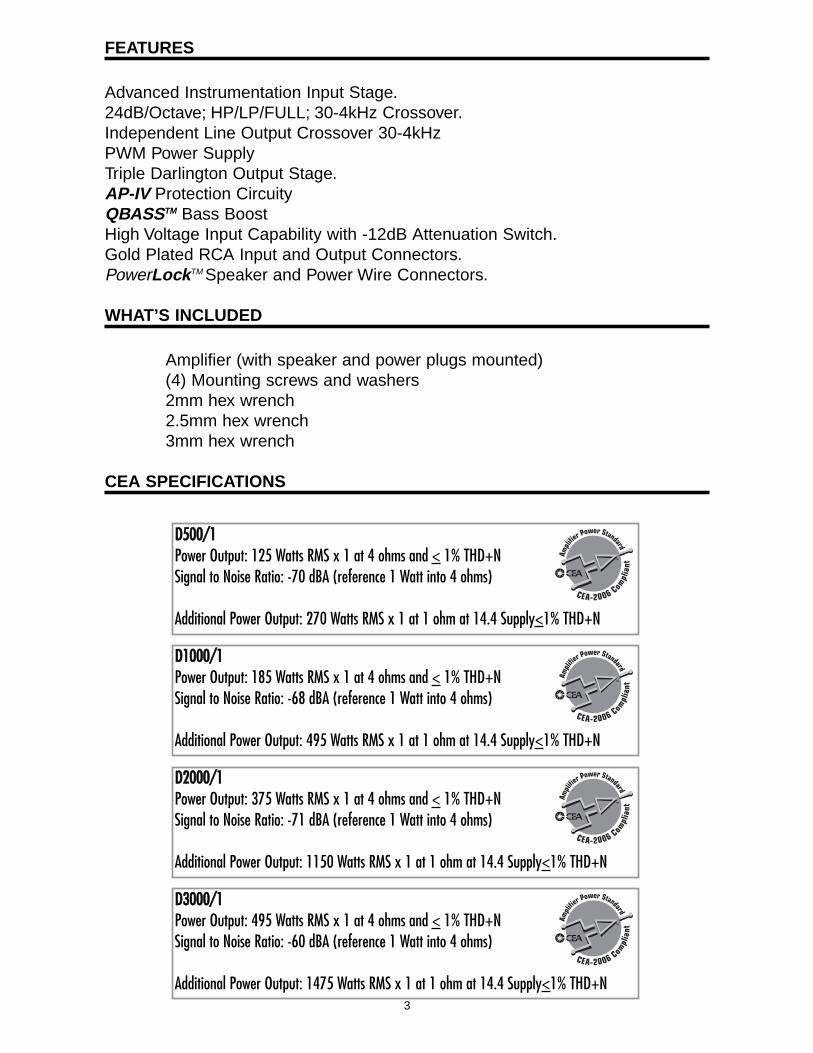
FEATURES
Advanced Instrumentation Input Stage.24dB/Octave; HP/LP/FULL; 30-4kHz Crossover.Independent Line Output Crossover 30-4kHzPWM Power SupplyTriple Darlington Output Stage.AP-IV Protection CircuityQBASSTM Bass BoostHigh Voltage Input Capability with -12dB Attenuation Switch.Gold Plated RCA Input and Output Connectors.PowerLockTM Speaker and Power Wire Connectors.
WHAT’S INCLUDED
Amplifier (with speaker and power plugs mounted)(4) Mounting screws and washers2mm hex wrench2.5mm hex wrench3mm hex wrench
CEA SPECIFICATIONS
3
DD550000//11Power Output: 125 Watts RMS x 1 at 4 ohms and < 1% THD+NSignal to Noise Ratio: -70 dBA (reference 1 Watt into 4 ohms)
Additional Power Output: 270 Watts RMS x 1 at 1 ohm at 14.4 Supply<1% THD+N
DD11000000//11Power Output: 185 Watts RMS x 1 at 4 ohms and < 1% THD+NSignal to Noise Ratio: -68 dBA (reference 1 Watt into 4 ohms)
Additional Power Output: 495 Watts RMS x 1 at 1 ohm at 14.4 Supply<1% THD+N
DD22000000//11Power Output: 375 Watts RMS x 1 at 4 ohms and < 1% THD+NSignal to Noise Ratio: -71 dBA (reference 1 Watt into 4 ohms)
Additional Power Output: 1150 Watts RMS x 1 at 1 ohm at 14.4 Supply<1% THD+N
DD33000000//11Power Output: 495 Watts RMS x 1 at 4 ohms and < 1% THD+NSignal to Noise Ratio: -60 dBA (reference 1 Watt into 4 ohms)
Additional Power Output: 1475 Watts RMS x 1 at 1 ohm at 14.4 Supply<1% THD+N
SPECIFICATIONS
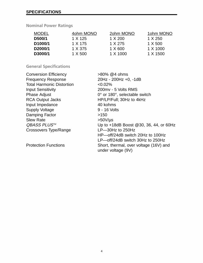
Nominal Power Ratings
MODEL 4ohm MONO 2ohm MONO 1ohm MONOD500/1 1 X 125 1 X 200 1 X 250D1000/1 1 X 175 1 X 275 1 X 500D2000/1 1 X 375 1 X 600 1 X 1000D3000/1 1 X 500 1 X 1000 1 X 1500
General Specifications
Conversion Efficiency >80% @4 ohmsFrequency Response 20Hz - 200Hz +0, -1dBTotal Harmonic Distortion <0.02%Input Sensitivity 200mv - 5 Volts RMSPhase Adjust 0° or 180°, selectable switchRCA Output Jacks HP/LP/Full; 30Hz to 4kHzInput Impedance 40 kohmsSupply Voltage 9 - 16 VoltsDamping Factor >150Slew Rate >50V/µsQBASS PLUSTM Up to +18dB Boost @30, 36, 44, or 60HzCrossovers Type/Range LP—30Hz to 250Hz
HP—off/24dB switch 20Hz to 100HzLP—off/24dB switch 30Hz to 250Hz
Protection Functions Short, thermal, over voltage (16V) and under voltage (9V)
4

5
Fuse Requirements
You will need to install an in-line fuse or circuit breaker in the powerwire within 18” of the battery. This fuse or circuit breaker is to protectyour vehicle from fire in case the power wire shorts to the vehiclebody. If you are only using one amplifier, use the fuse ratingindicated in this chart. If you are using more than one amplifier, addup the fuse ratings for all the amplifiers. This sum is the rating foryour fuse or circuit breaker. You may also want to add a powerdistribution block near your amplifiers to distribute large gaugepower cable to multiple amplifiers.
Dimensions
Length Width HeightD500/1 12-½” 10-½” 2-¾”
D1000/1 21-½” 10-½” 2-¾”
D2000/1 24-¾” 10-½” 2-¾”
D3000/1 29-3/8” 10-½” 2-¾”
Amp FuseD500/1 40 AD1000/1 50 AD2000/1 100 AD3000/1 150 A
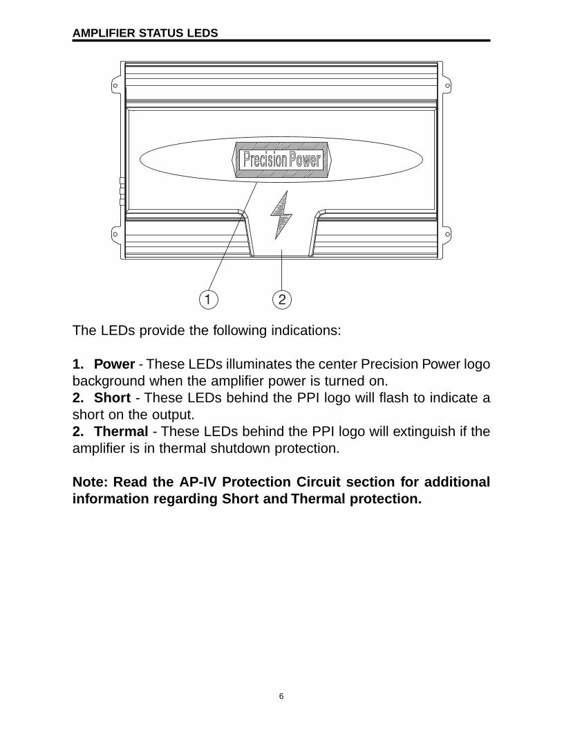
AMPLIFIER STATUS LEDS
The LEDs provide the following indications:
1. Power - These LEDs illuminates the center Precision Power logobackground when the amplifier power is turned on.2. Short - These LEDs behind the PPI logo will flash to indicate ashort on the output.2. Thermal - These LEDs behind the PPI logo will extinguish if theamplifier is in thermal shutdown protection.
Note: Read the AP-IV Protection Circuit section for additionalinformation regarding Short and Thermal protection.
1 2
6
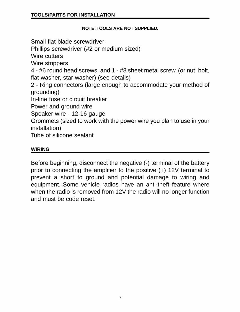
TOOLS/PARTS FOR INSTALLATION
NOTE: TOOLS ARE NOT SUPPLIED.
Small flat blade screwdriverPhillips screwdriver (#2 or medium sized)Wire cuttersWire strippers4 - #6 round head screws, and 1 - #8 sheet metal screw. (or nut, bolt,flat washer, star washer) (see details)2 - Ring connectors (large enough to accommodate your method ofgrounding)In-line fuse or circuit breakerPower and ground wireSpeaker wire - 12-16 gaugeGrommets (sized to work with the power wire you plan to use in yourinstallation)Tube of silicone sealant
WIRING
Before beginning, disconnect the negative (-) terminal of the batteryprior to connecting the amplifier to the positive (+) 12V terminal toprevent a short to ground and potential damage to wiring andequipment. Some vehicle radios have an anti-theft feature wherewhen the radio is removed from 12V the radio will no longer functionand must be code reset.
7
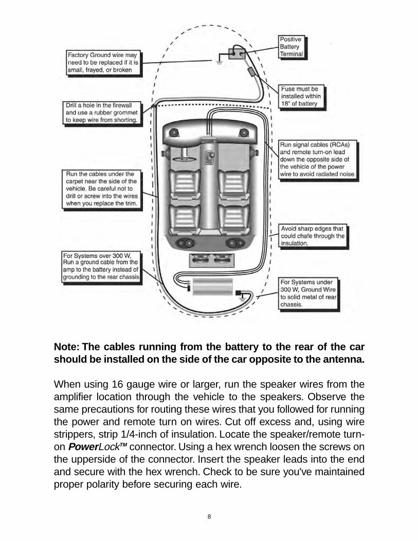
Note: The cables running from the battery to the rear of the carshould be installed on the side of the car opposite to the antenna.
When using 16 gauge wire or larger, run the speaker wires from theamplifier location through the vehicle to the speakers. Observe thesame precautions for routing these wires that you followed for runningthe power and remote turn on wires. Cut off excess and, using wirestrippers, strip 1/4-inch of insulation. Locate the speaker/remote turn-on PowerLockTM connector. Using a hex wrench loosen the screws onthe upperside of the connector. Insert the speaker leads into the endand secure with the hex wrench. Check to be sure you've maintainedproper polarity before securing each wire.
8
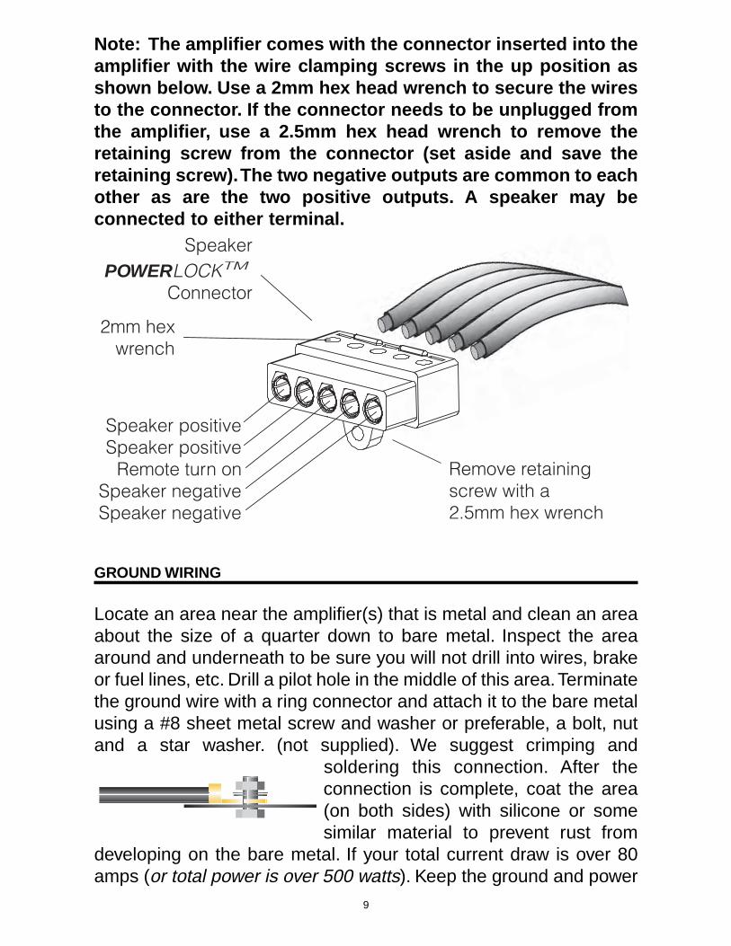
Note: The amplifier comes with the connector inserted into theamplifier with the wire clamping screws in the up position asshown below. Use a 2mm hex head wrench to secure the wiresto the connector. If the connector needs to be unplugged fromthe amplifier, use a 2.5mm hex head wrench to remove theretaining screw from the connector (set aside and save theretaining screw).The two negative outputs are common to eachother as are the two positive outputs. A speaker may beconnected to either terminal.
GROUND WIRING
Locate an area near the amplifier(s) that is metal and clean an areaabout the size of a quarter down to bare metal. Inspect the areaaround and underneath to be sure you will not drill into wires, brakeor fuel lines, etc. Drill a pilot hole in the middle of this area.Terminatethe ground wire with a ring connector and attach it to the bare metalusing a #8 sheet metal screw and washer or preferable, a bolt, nutand a star washer. (not supplied). We suggest crimping and
soldering this connection. After theconnection is complete, coat the area(on both sides) with silicone or somesimilar material to prevent rust from
developing on the bare metal. If your total current draw is over 80amps (or total power is over 500 watts). Keep the ground and power
SpeakerPOWERLOCKTM
Connector
Speaker positiveSpeaker positive
Remote turn onSpeaker negativeSpeaker negative
2mm hexwrench
Remove retainingscrew with a2.5mm hex wrench
9
wires as close together as possible, and use the same gauge wirefor both.This will ensure that you have a good ground path, and mayeliminate such potential problems as engine noise and overheatedamplifiers.
CHARGING SYSTEM
If your total current draw is over 100 amps (or total output power isover 600 watts), you are probably exceeding the capability of yourcharging system. Dimming lights and fluctuating voltage are solidindicators that you need to upgrade your alternator, battery, or both.You should also check the condition and current capacity of thestock battery negative cable and connections, and replace orupgrade as necessary. Keep in mind that your amplifiers simplyconvert electrical energy to acoustical energy, and any electricaldeficiency will compromise the performance of your sound system.For more information about charging system upgrades, see youlocal authorized Precision PowerTM Dealer or call Precision PowerTM
Technical Support at 1-800-62POWER x2033.
CURRENT DRAW
The following is a basic formula to be used as a guide to determinecurrent draw. Your new amplifier is more efficient than most otheramplifiers. This formula is to be used as a guideline. Using wire of alarger gauge can only improve the current transfer of your system.Do NOT use smaller wire gauge.
Total RMS output X 1.3 = Total Input Wattage
Total Input Wattage = Current Draw (in Amps)Supply Voltage
Example: A PPI amplifier has one channel at 1000 watts RMSrating into 4 ohms.
You would use the formula in the following way:
1000 W X 1.3 = 1300 watts
10

1300W = 108 Amps total current draw12V
If the same amplifier is driven into a 2 ohm load, double it’s 4 ohmRMS rating. These amplifiers will effectively double their power atthis load.
1000W X 1.3 X 2 = 2600 watts
2600W = 217 Amps total current draw12V
If you are using more than one amplifier, add up the total currentdraw for all of them and choose the appropriate gauge based on thegrand total.
POWER WIRE SIZE
A minimum of 8 gauge or a maximum of 4 gauge wire isrecommended dependent on the application.
The ground wire must be the same gauge as the power wire.
11
POWERLOCK CONNECTORS
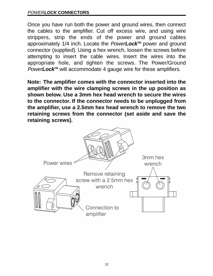
Once you have run both the power and ground wires, then connectthe cables to the amplifier. Cut off excess wire, and using wirestrippers, strip the ends of the power and ground cablesapproximately 1/4 inch. Locate the PowerLockTM power and groundconnector (supplied). Using a hex wrench, loosen the screws beforeattempting to insert the cable wires. Insert the wires into theappropriate hole, and tighten the screws. The Power/GroundPowerLockTM will accommodate 4 gauge wire for these amplifiers.
Note: The amplifier comes with the connector inserted into theamplifier with the wire clamping screws in the up position asshown below. Use a 3mm hex head wrench to secure the wiresto the connector. If the connector needs to be unplugged fromthe amplifier, use a 2.5mm hex head wrench to remove the tworetaining screws from the connector (set aside and save theretaining screws).
Power wires
Connection toamplifier
3mm hexwrench
Remove retainingscrew with a 2.5mm hex
wrench
12

FRONT PLATE DIAGRAMS
1. Cooling Plenums: Maintain a minimum 2” clearance aroundcooling plenums for proper amplifier cooling.2. Speaker/Remote Connector: The PowerLockTM speakerconnector.3. Output Freq. Control: Use this control to adjust the sub bassoutput signal crossover frequency from 30Hz to 4kHz. (See theCrossover Frequency chart in this manual).4. Output HP/LP/FULL Switch: Select the desired crossoversetting HP/LP/FULL for the signal of the RCA outputs.5. LPF Frequency Control: Allows adjustment of the LPF between30Hz and 250Hz.6 & 7. QBASSTM 1 and QBASSTM 2 Freq.: Use these switches,QBASSTM 1 and QBASSTM 2 to program the QBASS PLUSTM circuitfrequency.8. Xover FULL/LP/HP Switch: Select the desired crossover settingFULL/HP.9. Sub Sonic Adjustment: Adjusts the crossover between 20Hzand 100Hz.10. Gain: Use this control to match the output level of the sourceunit to the amplifier.11. Input: Plug in the RCA leads from your source here.
���
�
������� ��
��
��� �����������
����������������������� ������ ����������������������������������������������
�
�����������
�
����������� �����
�
�������
�����
���������
����������
� � � ����
���������
������������
13
12. -12dB Input Attenuation: Push this switch ‘IN’ for high voltage(4V-12V) capability. This button pushed ‘IN’ must be used forspeaker level input on common ground head-units or for highvoltage line drivers.13. Phase: These switch sets the phase of the output relative to theamplifier input.14. RCA Outputs: RCA outputs provide HP/LP/FULL 30-4kHzsignal to another amplifier.
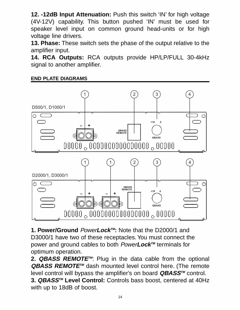
END PLATE DIAGRAMS
1. Power/Ground PowerLockTM: Note that the D2000/1 andD3000/1 have two of these receptacles. You must connect thepower and ground cables to both PowerLockTM terminals foroptimum operation.2. QBASS REMOTETM: Plug in the data cable from the optionalQBASS REMOTETM dash mounted level control here. (The remotelevel control will bypass the amplifier’s on board QBASSTM control.3. QBASSTM Level Control: Controls bass boost, centered at 40Hzwith up to 18dB of boost.
�� ������
��
����������
� � ��
������� ��������
�
�� ������
��
�����������
� � � �
����� ��������
14

4. Cooling Plenums: Maintain a minimum 2” clearance aroundcooling plenums for proper amplifier cooling.
INPUTS
There are two sets of RCA jacks on the front end of your amplifier.The RCA cables from your source unit go in the set labeledINPUTS. If your source unit doesn’t have RCA outputs, then add aset of RCA plugs (available at your dealer) to your front or rear setof speaker leads (see drawing below). Plug them into the inputjacks, and push in the -12dB input attenuation switch.
ADVANCED INSTRUMENTATION INPUT
The Advanced Instrumentation Input has been incorporated fromthe legendary Precision PowerTM 2500F1. This circuit completelyisolates the chassis ground from the audio circuit of the amplifierand reduces noise radiated into your signal cables by up to 40dB.This is equivalent to a noise reduction of approximately one hundredtimes what the noise level would be without this circuitry. It providesall the benefits of a true balanced line without the need of anyspecial cables (see diagram below). This type of input works withany conventional RCA cables.
(+) Positive
(-) Negative
LEFT input
(+) Positive
(-) Negative
RIGHT input
eject
VOLUME
BASS TREBLE
RIGHTLEFT
BALANCE TRACK
REVERSEFOWARD
1 2 3 4
8765
PPI MAR KET ING DPT
Trk 1
SOURCE Headunit
15
QBASS PLUS SPECIFICATIONS
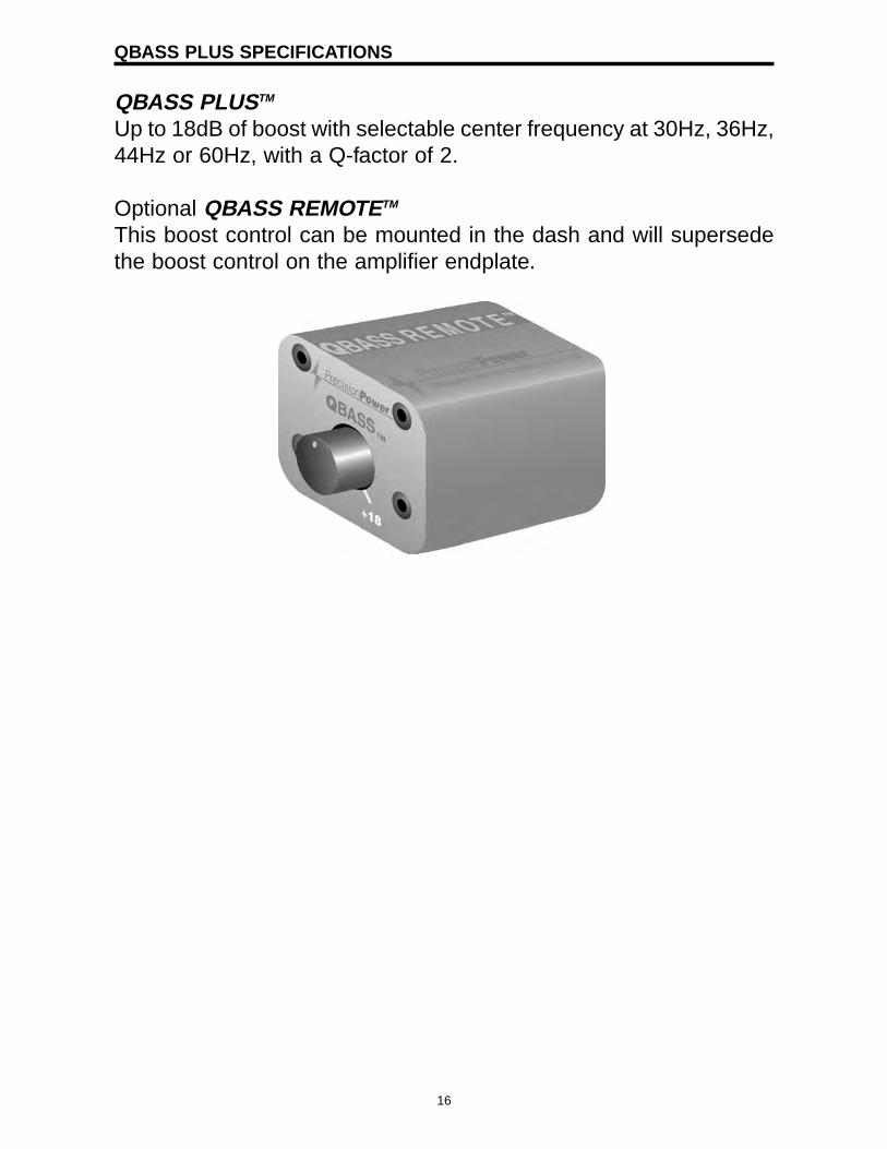
QBASS PLUSTM
Up to 18dB of boost with selectable center frequency at 30Hz, 36Hz,44Hz or 60Hz, with a Q-factor of 2.
Optional QBASS REMOTETM
This boost control can be mounted in the dash and will supersedethe boost control on the amplifier endplate.
16
QBASS PLUS/QBASS REMOTE
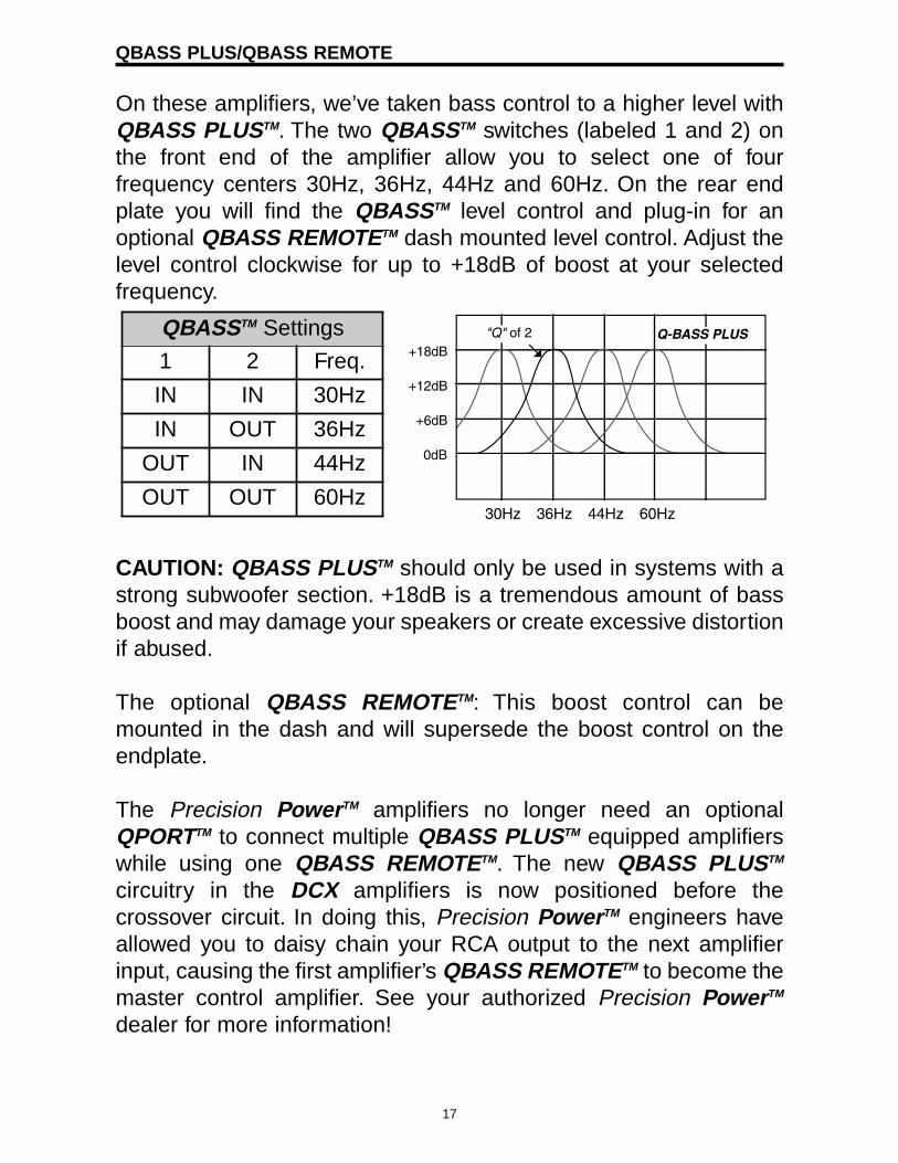
On these amplifiers, we’ve taken bass control to a higher level withQBASS PLUSTM. The two QBASSTM switches (labeled 1 and 2) onthe front end of the amplifier allow you to select one of fourfrequency centers 30Hz, 36Hz, 44Hz and 60Hz. On the rear endplate you will find the QBASSTM level control and plug-in for anoptional QBASS REMOTETM dash mounted level control. Adjust thelevel control clockwise for up to +18dB of boost at your selectedfrequency.
CAUTION: QBASS PLUSTM should only be used in systems with astrong subwoofer section. +18dB is a tremendous amount of bassboost and may damage your speakers or create excessive distortionif abused.
The optional QBASS REMOTETM: This boost control can bemounted in the dash and will supersede the boost control on theendplate.
The Precision PowerTM amplifiers no longer need an optionalQPORTTM to connect multiple QBASS PLUSTM equipped amplifierswhile using one QBASS REMOTETM. The new QBASS PLUSTM
circuitry in the DCX amplifiers is now positioned before thecrossover circuit. In doing this, Precision PowerTM engineers haveallowed you to daisy chain your RCA output to the next amplifierinput, causing the first amplifier’s QBASS REMOTETM to become themaster control amplifier. See your authorized Precision PowerTM
dealer for more information!
QBASSTM Settings
1 2 Freq.
IN IN 30Hz
IN OUT 36Hz
OUT IN 44Hz
OUT OUT 60Hz
17

TC-X CROSSOVER
Your new amplifier has a TC-X Crossover (Total Control X-over®)30Hz-4kHz (see this guide for Crossover Chart).12dB per octavephase correlated crossover built-in to provide superior systemflexibility without the added expense and installation of an outboardcrossover. The speaker outputs of your amplifier are high pass, lowpass, or all-pass according to the HP/LP/FULL switch on the frontendplate. You would choose low pass (middle position of switch) touse this amplifier for subwoofers, choose high pass (left position ofswitch), or full (right position of switch) to use this amplifier for fullrange speakers.
The RCA outputs are controlled by a separate HP/LP/FULL switch,and are always independent of the speaker output crossover. Aswell as being able to independently select HP/LP/FULL, your newamplifier allows independent selection of frequencies from 30Hz-4kHz (see Crossover Detent Chart in this guide).
D500/1, D1000/1, D2000/1, and D3000/1
Output - 24dB/Octave, Detented High Pass 30Hz-4kHzOutput - 12dB/Octave, Detented; HP/LP/FULLSub-Sonic - 12dB/Octave Detented; High Pass; 5Hz-80HzQBASS PLUSTM - on Front Channel - up to 18dB @ 30, 36, 44, 60Hz
18

CROSSOVER DETENT CHART
Detent #Low Pass
Frequency (Hz)@ -3dB
High PassFrequency (Hz)
@ -3dB1234567891011121314151617181920212223242526272829303132333435363738394041
3131313232343639424550555865717888
100115119124131137142149157165176190205210213216220224228234238242242
272828282829303133353740424548505255586270757580808285859095
100100103108108108108110110110110
19
ADJUSTING INPUT GAIN
1. Adjust all amplifier input gain controls to just above minimumsensitivity (fully counterclockwise).
2. Using the cleanest music source (CD) playing, turn up the headunit source volume until you can hear distortion. Now turn it down abit until you cannot hear the distortion (usually just below fullvolume).
3. Increase the amplifier gain (clockwise) until the onset of audibledistortion. Then decrease the gain to the point just before thedistortion starts. This setting minimizes background noise andprevents overload.
4. Repeat step 3 for any remaining independently controlledamplifiers (rear and subwoofer gain controls) in the system.
HIGH MASS INTERNAL HEATSINK
The unique heatsink on your amplifier has been designed with finson the inside of the aluminum extrusion. This allows for the transferof heat from the circuitry to the heatsink fins and out through thevents in the endplates. Be sure you provide ample space around theamplifier for cooling: at least 2” on all sides.
AP-IV PROTECTION CIRCUIT
Short Circuit Protection engaged: These amplifiers will turn off andtry to come back on immediately. The amplifier will cycle like thisindefinitely with “blips” of sound each time. If this is the case, checkyour speakers and wiring for low impedance and short circuits.Thermal Protection engaged. The amplifier will turn off and after aminute or so will come back on. In this case, ensure that there isnothing blocking the normal convection airflow of the amplifier. Noobstruction should be within 2” of the amplifier on all sides.
Note: Low battery voltage will cause the amplifier to runwarmer and possibly damage the amplifier.TROUBLESHOOTING
20

NO SOUND Is the LED illuminated?YES NO
Check Power and Remoteturn-on wire for voltage.Make sure the ground wire is secure.
STILL NO SOUNDSee your Authorized Precision PowerTM Dealer or call 1-800-62POWER.
SOUND IN ONE CHANNEL ONLY
Reverse the left and right speakers by unplugging the speaker connector,turning it over and plugging it back in.
SOUND IS NOW INOPPOSITE CHANNEL SAME CHANNELReverse RCA inputs. Problem is in the speaker or
speaker wire of the silent channel.
SOUND IS NOW INOPPOSITE CHANNEL SAME CHANNELReverse RCA inputs Problem is in the amplifier.at head unit. See your local Authorized
Precision PowerTM Dealer or call 1-800-62POWER.
SOUND IS NOW INOPPOSITE CHANNEL SAME CHANNELProblem is in the head Problem is in the RCA unit or before the amplifier. cables.
21

LIMITED TWO YEAR CONSUMER WARRANTY:
Directed Electronics promises to the original purchaser, to replace this productshould it prove to be defective in workmanship or material under normal use, fora period of two years from the date of purchase by the dealer as indicated by thedate code marking of the product PROVIDED the product was installed by anauthorized Directed dealer. During this two-year period, there will be no charge forthis replacement PROVIDED the unit is returned to Directed, shipping pre-paid. Ifthe unit is installed by anyone other than an authorized Directed dealer, thewarranty period will be 1 year from the date of purchase by the dealer as indicatedby the date code marking of the product. During this 1-year period there will be nocharge for this replacement PROVIDED the unit is returned to Directed, shippingpre-paid. This warranty is non-transferable and does not apply to any unit that hasbeen modified or used in a manner contrary to its intended purpose, and does notcover damage to the unit caused by installation or removal of the unit. Thiswarranty is void if the product has been damaged by accident or unreasonableuse, neglect, improper service or other causes not arising out of defects inmaterials or construction. ALL WARRANTIES INCLUDING BUT NOT LIMITEDTO EXPRESS WARRANTY, IMPLIED WARRANTY, WARRANTY OFMERCHANTABILITY, FITNESS FOR PARTICULAR PURPOSE, ANDWARRANTY OF NON-INFRINGEMENT OF INTELLECTUAL PROPERTY AREEXPRESSLY EXCLUDED TO THE MAXIMUM EXTENT ALLOWED BY LAW,AND DIRECTED NEITHER ASSUMES NOR AUTHORIZES ANY PERSON TOASSUME FOR IT ANY LIABILITY IN CONNECTION WITH THE SALE OF THEPRODUCT. DIRECTED HAS ABSOLUTELY NO LIABILITY FOR ANY AND ALLACTS OF THIRD PARTIES INCLUDING ITS AUTHORIZED DEALERS ORINSTALLERS. Unit must be returned to Directed, postage pre-paid, with:consumer’s name, telephone number, and address, authorized dealer’s name andaddress, and product description. IN ORDER FOR THIS WARRANTY TO BEVALID, YOUR UNIT MUST BE SHIPPED WITH PROOF OF INSTALLATION BYAN AUTHORIZED DIRECTED DEALER. ALL UNITS RECEIVED BY DIRECTEDFOR WARRANTY REPAIR WITHOUT PROOF OF DIRECTED DEALERINSTALLATION WILL BE COVERED BY THE LIMITED 1-YEAR PARTS ANDLABOR WARRANTY. Note: This warranty does not cover labor costs for theremoval and reinstallation of the unit. BY PURCHASING THIS PRODUCT, THECONSUMER AGREES AND CONSENTS THAT ALL DISPUTES BETWEEN THECONSUMER AND Directed SHALL BE RESOLVED IN ACCORDANCE WITHCALIFORNIA LAWS IN SAN DIEGO COUNTY, CALIFORNIA.
© 2005 Directed Electronics, All rights reserved. G48300.05.10.15 12-05