amtek training aman (11 me-06)
TRANSCRIPT

INDUSTRIAL TRAINING REPORT
MPT AMTEK AUTOMOTIVE LTD.
(RING GEAR PRODUCTION)
9th Feb 2015 - 9th Aug 2015
Department of Mechanical Engineering B.M. COLLEGE OF TECHNOLOGY & MANAGEMENT
M.D. UNIVERSITY, ROHTAK (HR)
Submitted by
AMAN KUMAR
Roll No. 11-ME-06
Under the Guidance of
Mr. MANISH KUMAR Mr. MAHENDER SINGH
(Faculty Coordinator) (Production Head) H.O.D, Mechanical Engg. MPT AMTEK AUTOMOTIVE LTD. BMCTM, M.D. University Dharuhera, Rewari

2
MAY -2015
DECLARATION
I hereby declare that the project work entitled “Ring Gear Production” is an authentic record
of my own work carried out at MPT AMTEK AUTO LTD. As requirements of six month
Industrial Training for the award of the degree of B.Tech. At B.M. College Technology &
Management, M.D University, Rohatak under the guidance of Mr. Mahender Singh from 9th Feb
2015 to 9th Aug. 2015.
_______________
Aman Kumar
(11-ME-06)
Date: ____________
Certified that the above statement made by the student is correct to the best of our knowledge and
belief.
Mr. MANISH KUMAR Mr. MAHENDER SINGH
(Faculty Coordinator) (Production Head)
H.O.D, Mechanical Engg. MPT AMTEK AUTOMOTIVE LTD. BMCTM, M.D. University Dharuhera, Rewari

3
ACKNOWLEDGEMENT
Industrial training is an indispensable part of our engineering curriculum. It provides the students
an opportunity to gain experience on the practical applications of their knowledge. My training at
MPT AMTEK AUTO LTD. Dharuhera has been very fruitful. I sure that the hands of
experience I am gaining here will go a long way towards making me a competent engineer.
I would like to start the series of thanks, which might not be covered in this page, with my Industry
Guide Mr. PAWAN TYAGI who always entertained me and clear my doubts in the plant where
the production takes place. Even though he has a busy schedule he never left me, feel alone in the
plant. Mr. PAWAN TYAGI is a Senior Executive Engineer in Plant at MPT AMTEK PVT LTD,
Dharuhera.
I would like to thank production head Mr. MAHENDER SINGH who made me feel encouraged
and confident throughout the training period so that I can do my best in the Industry with ever-
filled confidence and patience.
My training would not be possible without the Human Resources Department of Mpt Amtek Pvt
Ltd. I would like to thank Mr. V S Yadav Hr head.
Last but not the least I would like to thank Mr. Deepak and all experienced engineers for providing
constant encouragement, support and valuable suggestion during the Training.
I hereby also declare that the contents in this report are true to the best of my knowledge.
AMAN KUMAR

4
ABSTRACT
I have done my training at “AMTEK MAGNA POWERTRAIN LTD.” On the basis
of what I have learnt in the company I am here by submitting a report. The report is
about the production products of AMTEK MAGNA Powertrain Auto Ltd .It also
include the specification of the products like ring gear specifications etc . A well
planned and properly executed industrial training helps a lot in calculating good
work culture. It is also about the company plant .The main motive of the industrial
training is to understanding the production of the company. The basic idea of the
training is to understand the production of the products made in MPT AMTEK. My
main focus on the production department. My report will also be consisting some
extra relevant information, as this information is the part of the whole procedure.
I hope you will like the Report and will appreciate its’ content and layout and will
find it useful for further study of the Ring Gear as a component. However I have
tried, my best to avoid any sort of errors but as I also belong to the Homo sapiens
species so one can except some errors or faults.
5
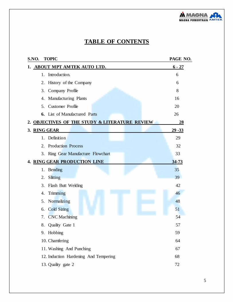
TABLE OF CONTENTS
S.NO. TOPIC PAGE NO.
1. ABOUT MPT AMTEK AUTO LTD. 6 - 27
1. Introduction. 6
2. History of the Company 6
3. Company Profile 8
4. Manufacturing Plants 16
5. Customer Profile 20
6. List of Manufactured Parts 26
2. OBJECTIVES OF THE STUDY & LITERATURE REVIEW 28
3. RING GEAR 29 -33
1. Definition 29
2. Production Process 32
3. Ring Gear Manufacture Flowchart 33
4. RING GEAR PRODUCTION LINE 34-73
1. Bending 35
2. Slitting 39
3. Flash Butt Welding 42
4. Trimming 46
5. Normalizing 48
6. Cold Sizing 51
7. CNC Machining 54
8. Quality Gate 1 57
9. Hobbing 59
10. Chamfering 64
11. Washing And Punching 67
12. Induction Hardening And Tempering 68
13. Quality gate 2 72

6
1.1 INTRODUCTION.
Amtek is a leading multi-national manufacturer of automotive components and assemblies with
production facilities located strategically across Asia, Europe and USA. The Group’s extensive
manufacturing capabilities encompass Iron and Aluminum Casting, Forging, Machining &
Assemblies.
Amtek Auto Ltd. has established itself amongst the top players in the Indian auto
ancillary industry and has also grown to become one of the largest manufacturers of Forgings,
Castings, Machined Components and Assemblies, which includes Piston Connecting Rod modules
and Gear Shifter Forks and Yokes, Flywheel Ring Gears in the country. Amtek also holds the
distinction of being among the largest manufacturer of Flywheel Ring Gear Assemblies and
Turbocharger Housings in the World. The uptrend in outsourcing by global OEM majors due to
rising cost pressures, the booming domestic Auto industry, particularly the high – growth diesel
engine segment, and Amtek’s aggressive acquisition and expansion strategy have propelled the
Company into a higher growth trajectory.
1.2 HISTORY OF THE COMPANY
The Amtek Group was established in the year 1985 with the incorporation of the Flagship
Company, Amtek Auto Limited. Over the course of next two decades, the group grew rapidly to
emerge as a global frontrunner in the automotive industry through a number of strategic
acquisitions across India, Europe and the USA, production segment rationalization measures. The
current turnover of the group exceeds $ 750 million.
ABOUT MPT AMTEK AUTO LTD. 1
UNIT

7
Amtek Group is a leading international manufacturer of automotive components and assemblies
with production facilities located strategically across North America, Europe & Asia. The Group's
extensive manufacturing capabilities encompass Sub assemblies, Iron, Gravity & Aluminum
Castings, Forgings, Complex Machining & Ring Gears Flywheel Assembly.
AAL entered into a joint venture with Benda Kogyo of Japan to form Benda Amtek in 1997 for
manufacturing of flywheel ring gears located Gurgoan. Later, in 1999 the company entered a JV
with Ateliers de Siccardi to form Amtek Siccardi for manufacturing crankshafts at Manesar. In
2001 the company acquired auto component manufacturing firm Wesman Halverscheidt Forgings.
The same year it also acquired Indusial Auto components Coimbatore (India).
In 2002 the company established an iron casting facility at Bhiwadi. The same year AAL acquired
14.8% equity stake in Ahmednagar Forgings. The next year in 2003 the company acquired an
additional 20% stake in Ahmednagar Forgings.
In 2006 the company formed 50:50 JV with Canada based Magna Power train to commence
manufacturing facility for 2–piece flex plate assemblies for automotive applications. It also
established a new manufacturing facility at Dharuhera (India) the same year.
In order to manufacture fractured connecting rod modules company entered JV with Magna
Powertrain to form MPT Magna India.The company set up another manufacturing facility at
Sanaswadi, Pune for forging, casting and machining in the year of 2007. The same year it acquired
Triplex– Ketlon Group– which was amongst the largest automotive precision machining
companies and it also had presence in UK.
In February 2008, the company formed 50:50 joint venture with American Railcar Industries in
order to diversify by the setting up of the company's Amtek Transportations systems division. In
June 2008 Amtek Transportation Systems became subsidiary of AAL
Amtek acquired Ahmednagar Forgings Limited (AFL) in order to establish a manufacturing
business in Western India, as there were a number of automotive companies which were being
supplied by AFL in that region. On 10 October 2002 the Company acquired 1,183,790 fully paid–
up equity shares of Rs.10 each in AFL, representing 14.8 percent. Of its issued, subscribed and
paid–up equity share capital, at a price of Rs. 34.50 per share from the promoters of AFL, their
friends, relatives and associates. The Company also entered into an agreement with the promoters
of AFL on 10 October 2002 to acquire from them an additional 2,457,660 fully paid equity shares
8
of Rs. 10 each, representing 30.72 percent. Of the issued, subscribed and paid–up capital of AFL,
at a price of Rs. 34.50 per share.
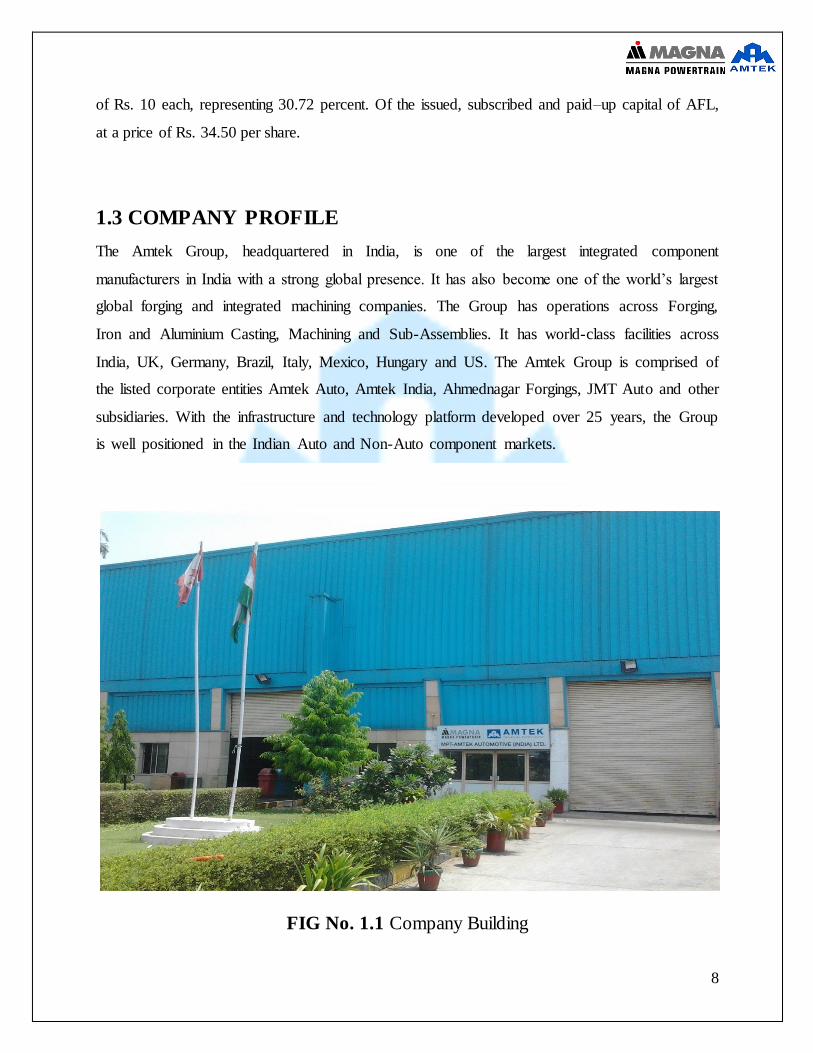
1.3 COMPANY PROFILE
The Amtek Group, headquartered in India, is one of the largest integrated component
manufacturers in India with a strong global presence. It has also become one of the world’s largest
global forging and integrated machining companies. The Group has operations across Forging,
Iron and Aluminium Casting, Machining and Sub-Assemblies. It has world-class facilities across
India, UK, Germany, Brazil, Italy, Mexico, Hungary and US. The Amtek Group is comprised of
the listed corporate entities Amtek Auto, Amtek India, Ahmednagar Forgings, JMT Auto and other
subsidiaries. With the infrastructure and technology platform developed over 25 years, the Group
is well positioned in the Indian Auto and Non-Auto component markets.
FIG No. 1.1 Company Building
9
Magna Powertrain and Amtek Establish a Joint Venture in India Magna Powertrain, an operating unit of Canadianbased
Magna International Inc., and Amtek Auto Limited today signed a joint venture
Agreement to establish a
Manufacturing facility outside of Delhi, India, for two piece
Flex plate assemblies for automotive applications.
Aurora, Ontario, Canada and New Delhi, India, October 31, 2006 — Magna Powertrain, an
operating unit of Canadian based
Magna International Inc., and Amtek Auto
Limited today signed a jointventure
Agreement to establish a manufacturing facility outside of Delhi, India, for two-piece
Flex plate assemblies for automotive applications.
Manufacturing operations of the joint venture are expected to commence late in 2007. The joint
venture will initially export flex plate assemblies entirely to European
Markets, with production to follow for the Indian market. Flex plate assemblies are used in
automobiles with automatic transmission systems.
The 50/50 joint venture between Magna Powertrain and Amtek expands on Amtek’s existing
relationship as a supplier of ring gears to Magna Powertrain’s North American
Operations. The joint venture represents a step forward in the expansion of Amtek’s customer base
and product portfolio, as well as its technological capabilities, and is
Expected to enhance the competitive positions of both Amtek and Magna Powertrain.
Günther Apfalter, President, Magna Powertrain Europe and Asia stated: “For Magna Powertrain
the joint venture is an important first step into the Indian market. Through
The formation of an alliance with Amtek, Magna Powertrain can make use of Amtek’s special
knowhow
In ring gear
Manufacturing and will benefit from the competitive cost level
In India.”

10
Regarding the agreement, John Flintham, CEO Worldwide
Operations of Amtek said: “This joint venture will be another milestone for the Amtek Group and
a step forward in
Expanding its customer base and product portfolio, as well as attaining a technological and
competitive edge in automotive component manufacturing.”
About Amtek
Amtek is market leader in the manufacture of a variety of fully finished automotive components
and assemblies for use in engine/drivetrain, transmission/powertrain and
Suspension systems for the global automotive industry
About Amtek
Amtek is market leader in the manufacture of a variety of fully finished automotive components
and assemblies for use in engine/drivetrain, transmission/powertrain and
Suspension systems for the global automotive industry.
About Magna Powertrain
Magna Powertrain, an operating unit of Magna International Inc., is engaged in the business of
the design, development, manufacture, assembly and supply of powertrain
and drivetrain products (and related devices) such as transaxles, gear boxes, PTO units, transfer
cases, four wheel drive and all-wheel drive units, and a wide variety of
Engine and transmission components, modules and systems for the global automotive industry.
Fig No. 1.2
11
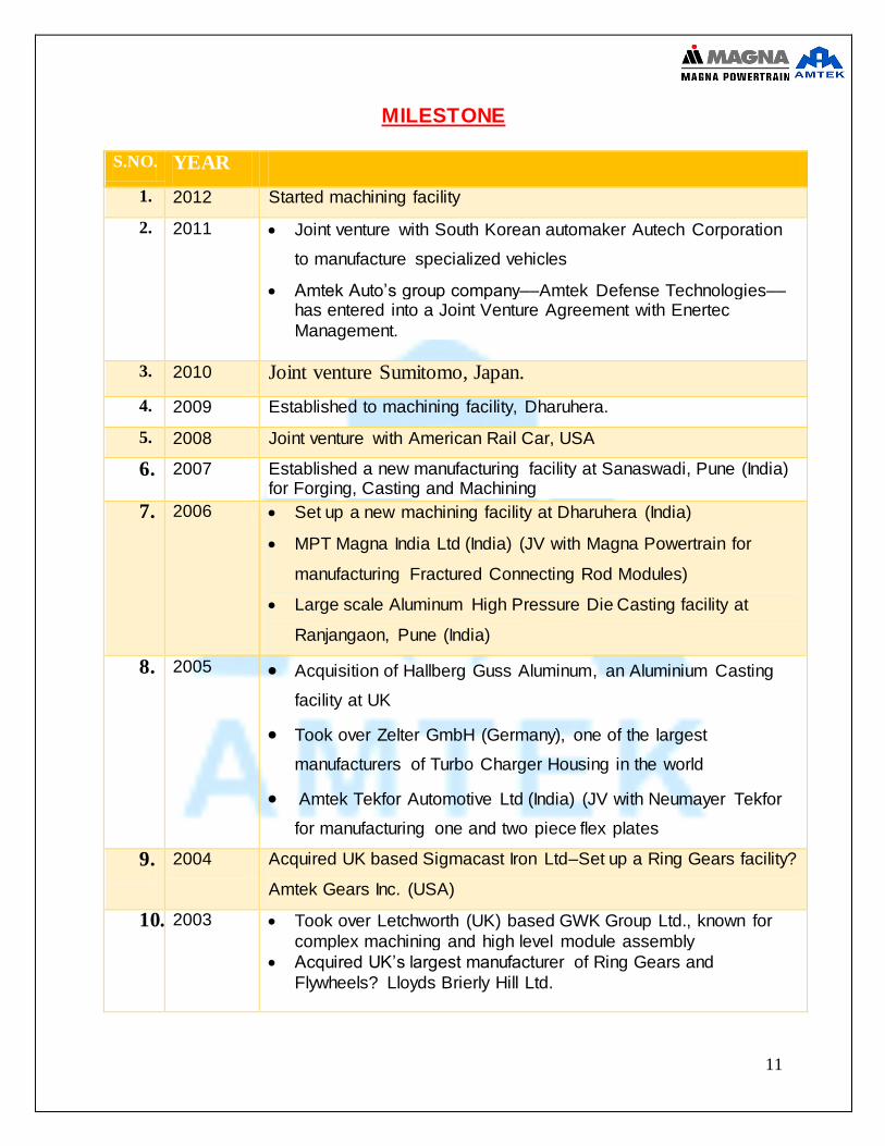
MILESTONE
S.NO. YEAR
1. 2012 Started machining facility
2. 2011 Joint venture with South Korean automaker Autech Corporation
to manufacture specialized vehicles
Amtek Auto’s group company––Amtek Defense Technologies––has entered into a Joint Venture Agreement with Enertec
Management.
3. 2010 Joint venture Sumitomo, Japan.
4. 2009 Established to machining facility, Dharuhera.
5. 2008 Joint venture with American Rail Car, USA
6. 2007 Established a new manufacturing facility at Sanaswadi, Pune (India) for Forging, Casting and Machining
7. 2006 Set up a new machining facility at Dharuhera (India)
MPT Magna India Ltd (India) (JV with Magna Powertrain for
manufacturing Fractured Connecting Rod Modules)
Large scale Aluminum High Pressure Die Casting facility at
Ranjangaon, Pune (India)
8. 2005 Acquisition of Hallberg Guss Aluminum, an Aluminium Casting
facility at UK
Took over Zelter GmbH (Germany), one of the largest
manufacturers of Turbo Charger Housing in the world
Amtek Tekfor Automotive Ltd (India) (JV with Neumayer Tekfor
for manufacturing one and two piece flex plates
9. 2004 Acquired UK based Sigmacast Iron Ltd–Set up a Ring Gears facility?
Amtek Gears Inc. (USA)
10. 2003 Took over Letchworth (UK) based GWK Group Ltd., known for
complex machining and high level module assembly
Acquired UK’s largest manufacturer of Ring Gears and
Flywheels? Lloyds Brierly Hill Ltd.

12
11. 2002 Acquired Midwest Mfg, a US based ring gears manufacturer
Ahmednagar Forgings (India) was taken over
Established an Iron Casting facility at Bhiwadi (India)
12. 2001 Acquisition of auto component manufacturing firm, Wesman
Halverscheidt Forgings (India)
Indusial Auto components Coimbatore (India), a fully automated
foundry with machining facilities, was taken over
13. 1999 Amtek Siccardi, Manesar (India) (JV with Ateliers de Siccardi for
Crankshaft manufacturing
14. 1998 A new Machining unit was set up at Gurgaon (India)
15. 1997 Benda Amtek Ltd Gurgaon (India) (JV with Benda Kogyo Japan for
Flywheel Ring Gears manufacturing)
16. 1996 Established a Machining unit at Gurgaon (India)
17. 1993 Initiation of forging operations at Gurgaon, India
18. 1987 Start of manufacturing at the Machining facility based at Sohna, India
Table No. 1.1
Different divisions of the company are:
Amtek Centre of Excellence (ACE)
Amtek Forging Division (AFD)
Amtek Iron Casting Division (AICD)
Amtek Aluminum Casting Division (AACD)
Amtek Automotive Machining Division (AAMD)
Amtek Ring Gear Division(ARGD)
Amtek JVS

13
Business Divisions
Forgings: -
Forging is the process of forming hot / cold metal. The Forging divisions of the group are Baddi
(H.P). Connecting Rods, Crankshafts, Steering Knuckles, Gears shifter Forks, Sector Gears &
Shafts, Stub Axles, Front Impact Beams etc. are some of the products in the Amtek Forging suite.
Castings: -
Casting is the process of forming from molten metal. The Group has facilities for Iron Castings at
Bhiwadi (Rajasthan), Baddi (H.P), Coimbatore (Tamil Nadu) & Tipton (UK). Besides Iron
Castings, Amtek has facilities for Aluminum Castings at Bourne (U.K) and is in the process of
commissioning another Aluminum Casting facility at Ranjangaon (Mah.).
Machining:-
Machining is the term used for a set of metal – cutting processes which are performed on Forgings
and / or Castings to give them the exact shape and size for assembling in the vehicle. The Group
has Machining facilities within India at Gurgaon (Haryana), Sanaswadi (Mah), Manesar &
Dharuhera (both in Haryana), Baddi (H.P), and across the World at Letch worth, Coventry &
Bourne (in U.K) & Hennef (Germany), Stanberry, Bay City & Kellogg (in USA).
Assembly: -
The Assembling activities are carried at Letch worth, Coventry, Gurgaon, Dharuhera, & Hennef
(Germany). The products include Bridge Fork Assemblies, Strut Assemblies, Wheel Corner
Modules, Axle Assemblies, Turbochargers, Piston Cylinder Modules, Spindle Assemblies, and
Fuel Delivery Systems.
14
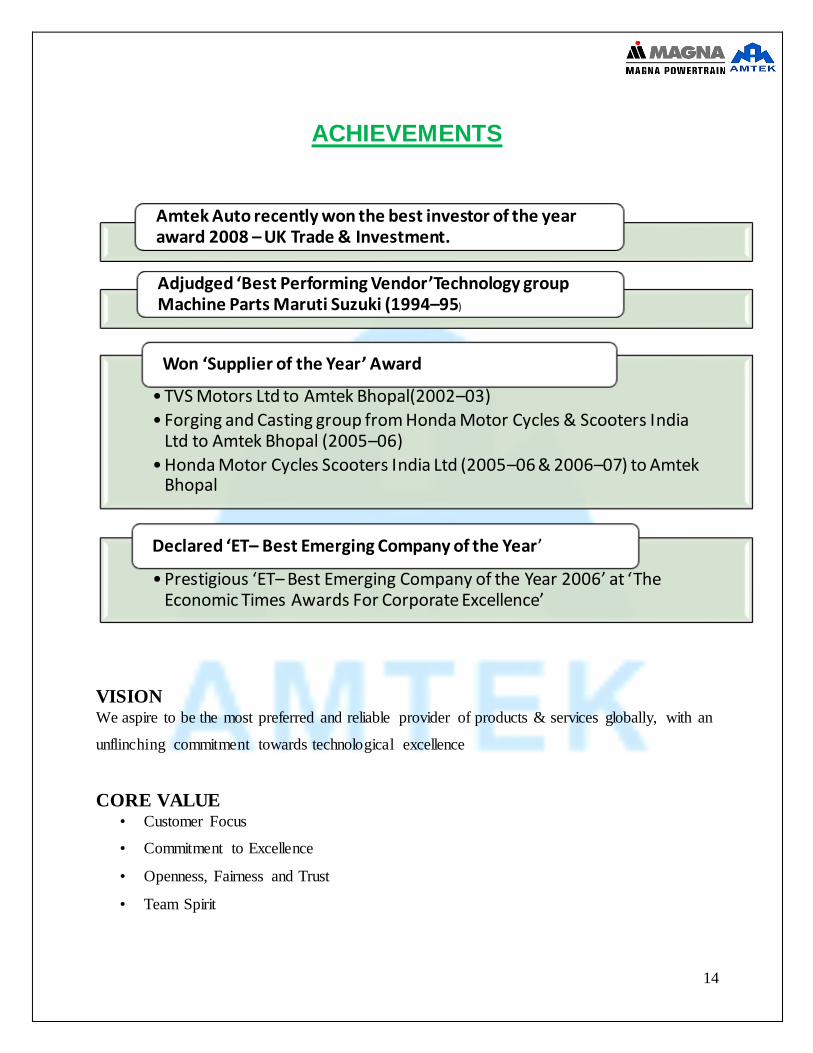
ACHIEVEMENTS
VISION
We aspire to be the most preferred and reliable provider of products & services globally, with an
unflinching commitment towards technological excellence
CORE VALUE • Customer Focus
• Commitment to Excellence
• Openness, Fairness and Trust
• Team Spirit
Amtek Auto recently won the best investor of the year award 2008 – UK Trade & Investment.
Adjudged ‘Best Performing Vendor’Technology group Machine Parts Maruti Suzuki (1994–95)
• TVS Motors Ltd to Amtek Bhopal(2002–03)
• Forging and Casting group from Honda Motor Cycles & Scooters India Ltd to Amtek Bhopal (2005–06)
• Honda Motor Cycles Scooters India Ltd (2005–06 & 2006–07) to Amtek Bhopal
Won ‘Supplier of the Year’ Award
• Prestigious ‘ET– Best Emerging Company of the Year 2006’ at ‘The Economic Times Awards For Corporate Excellence’
Declared ‘ET– Best Emerging Company of the Year’
15
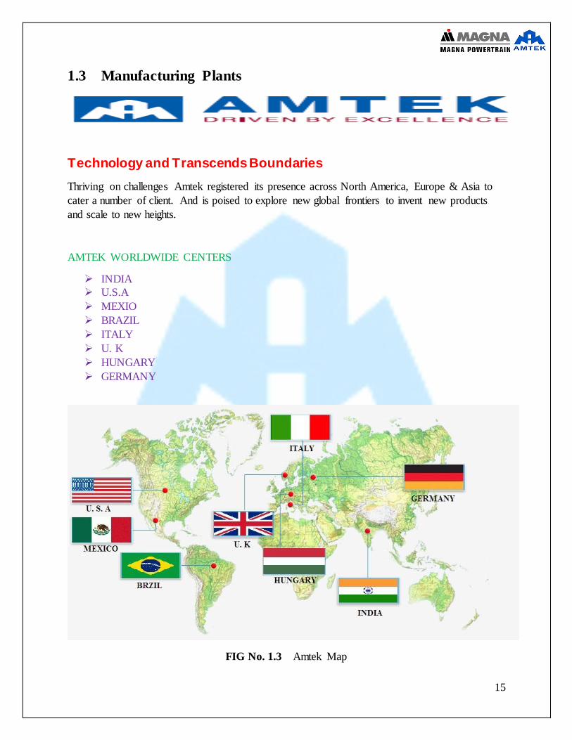
1.3 Manufacturing Plants
Technology and Transcends Boundaries
Thriving on challenges Amtek registered its presence across North America, Europe & Asia to
cater a number of client. And is poised to explore new global frontiers to invent new products
and scale to new heights.
AMTEK WORLDWIDE CENTERS
INDIA
U.S.A
MEXIO
BRAZIL
ITALY
U. K
HUNGARY
GERMANY
FIG No. 1.3 Amtek Map
16
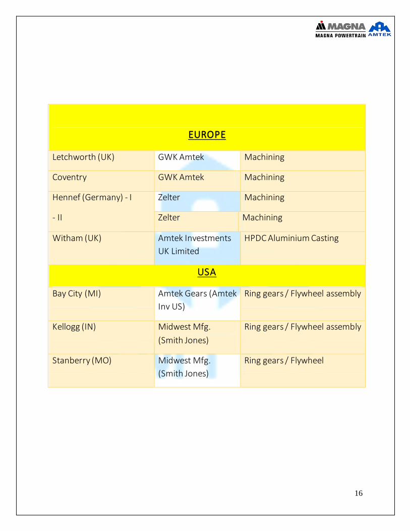
EUROPE
Letchworth (UK) GWK Amtek Machining
Coventry GWK Amtek Machining
Hennef (Germany) - I
- II
Zelter Machining
Zelter Machining
Witham (UK) Amtek Investments
UK Limited
HPDC Aluminium Casting
USA
Bay City (MI) Amtek Gears (Amtek
Inv US)
Ring gears / Flywheel assembly
Kellogg (IN) Midwest Mfg.
(Smith Jones)
Ring gears / Flywheel assembly
Stanberry (MO) Midwest Mfg.
(Smith Jones)
Ring gears / Flywheel
17
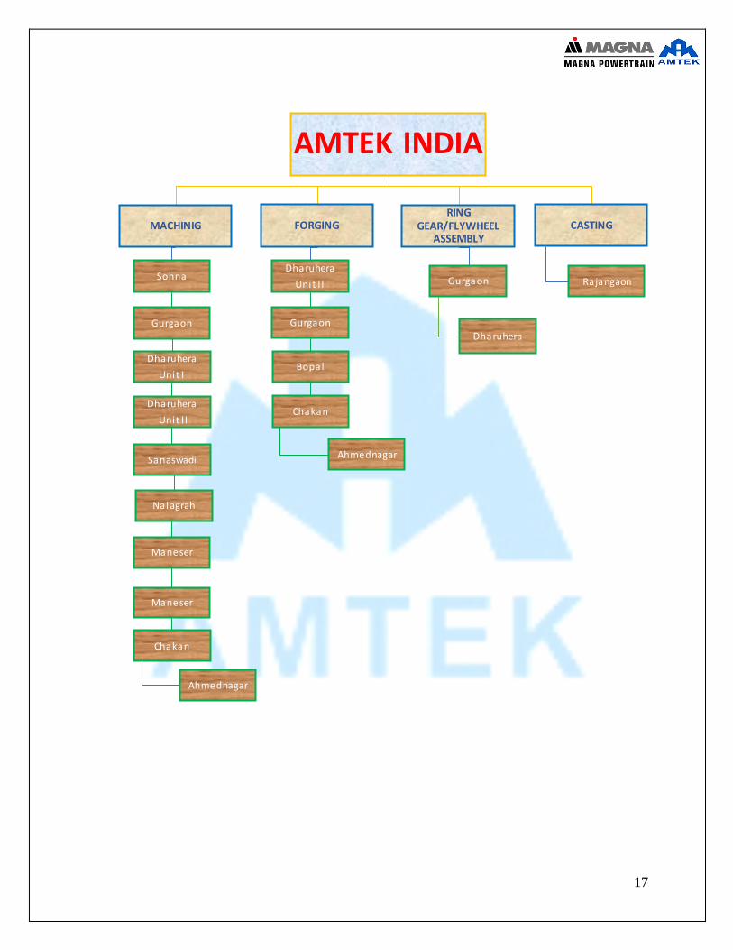
AMTEK INDIA
RING GEAR/FLYWHEEL
ASSEMBLY
Gurgaon
Dharuhera
CASTING
Rajangaon
FORGING
Dharuhera
Unit I I
Gurgaon
Bopal
Chakan
Ahmednagar
MACHINIG
Sohna
Gurgaon
Dharuhera
Unit I
Dharuhera
Unit I I
Sanaswadi
Nalagrah
Maneser
Maneser
Chakan
Ahmednagar

18
FIG No.1.4 Amtek across India
19
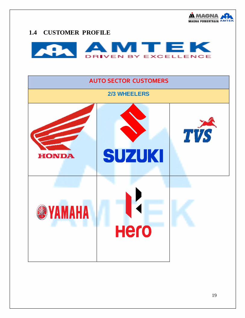
1.4 CUSTOMER PROFILE
AUTO SECTOR CUSTOMERS
2/3 WHEELERS

20
PASSENGER CARS

21
22
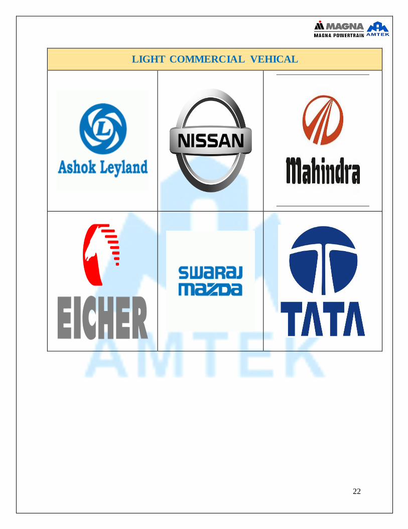
LIGHT COMMERCIAL VEHICAL

23
HEAVY COMMERCIAL VEHICAL
OIHER
24
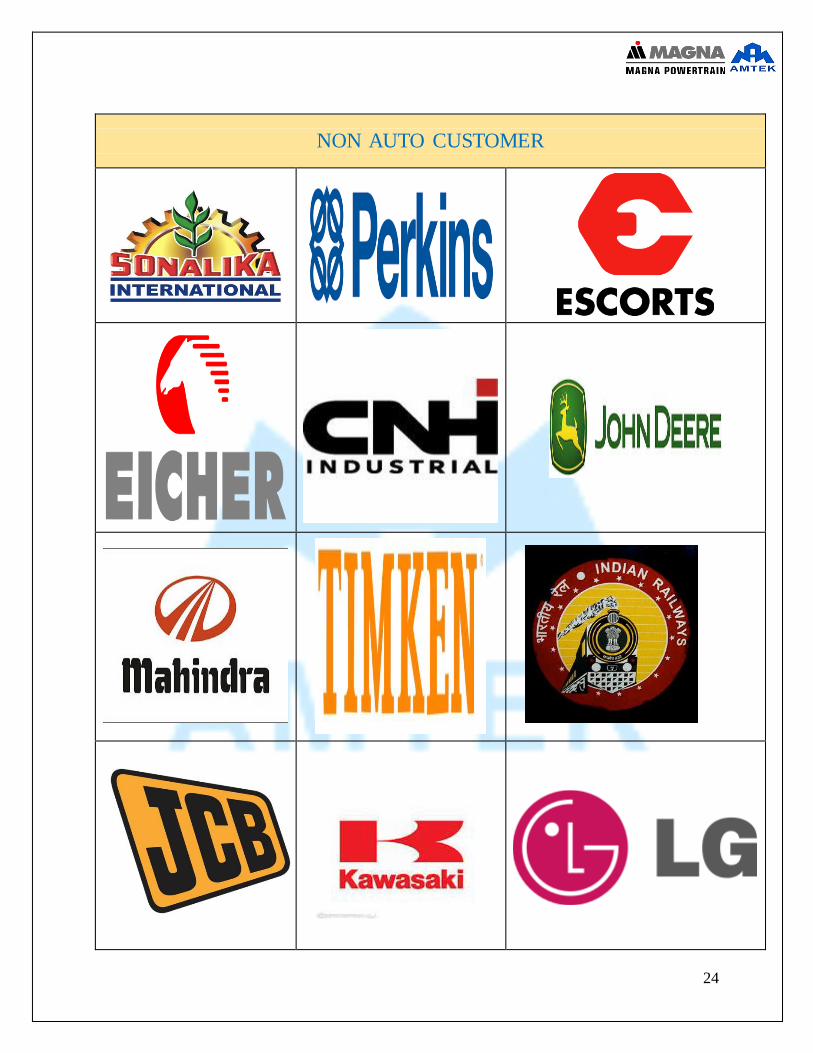
NON AUTO CUSTOMER
25
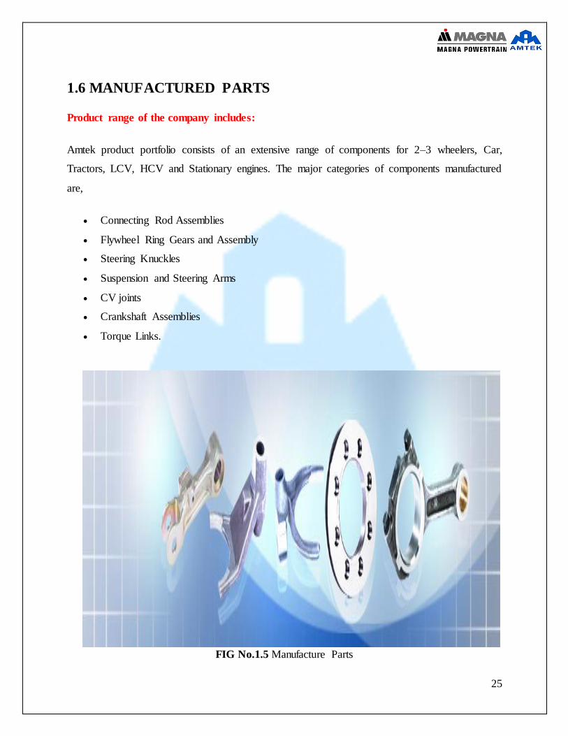
1.6 MANUFACTURED PARTS
Product range of the company includes:
Amtek product portfolio consists of an extensive range of components for 2–3 wheelers, Car,
Tractors, LCV, HCV and Stationary engines. The major categories of components manufactured
are,
Connecting Rod Assemblies
Flywheel Ring Gears and Assembly
Steering Knuckles
Suspension and Steering Arms
CV joints
Crankshaft Assemblies
Torque Links.
FIG No.1.5 Manufacture Parts

26
MODEL OF RING GEAR

27
The main objective of the Training is to study the Production process of the Amtek MAGNA
Powertrain Ltd. And to analyses the Production process and defects of the Amtek MAGNA
Powertrain Ltd... The study includes the study of all control plans of the products and machining
processes etc. The main objective in working with the production process is to calculate the
production rates with in time and without any defects.
My duty in company was to understanding and studies the production of Ring gears process. MPT
AMTEK deals with the production or machining of ring gear. It is a joint venture of Amtek group
OBJECTIVES OF THE STUDY & LITERATURE REVIEW 2
UNIT
28
DEFINITION:-
A starter ring gear, sometimes called a starter ring or ring gear, is a medium carbon steel ring
with teeth that is fitted on the periphery of a flex plate or flywheel of an internal combustion engine,
mostly for automotive or aircraft applications. The teeth of the starter ring are driven by the smaller
gear (the pinion) of the starter motor.
The primary function of the starter ring is to transfer torque from the starter motor pinion to the
flywheel or flex plate to rotate the engine to begin the cycle.
Manufacture
The starter ring gear is most commonly made by forming a length of square or rectangular steel
bar into a circle and welding the ends together. There then follow various operations such as
normalising (to remove stresses and improve the properties in the weld area), turning, generating
the teeth by gear hobbing and finally a heat-treatment operation(s). The teeth of the starter ring
need to be hardened in order to increase their strength and resist wear. The normal hardness at
pitch circle diameter is 45-55 HRC. The body of the ring is generally left untreated which gives
some ductility for shrinking onto a flywheel or welding to a flex plate.
Attachment
Engines with manual transmission usually have a heavy flywheel, typically 5 to 10 kg of cast iron,
with the starter ring gear shrunk onto the outside. This is done by heating the ring to around 200
°C to expand the ring which is then placed onto the flywheel, often held in firmly against a location
shoulder until cool. The interference fit renders the starter ring firmly attached to the flywheel. [1]
Engines with automatic transmissions instead have a pressed steel plate with the starter ring gear
usually welded onto the outside of the plate
RING GEAR 3
UNIT

29
FIG No. 3.1 Ring Gear
Fig No. 3.2 Ring Gear Use
30
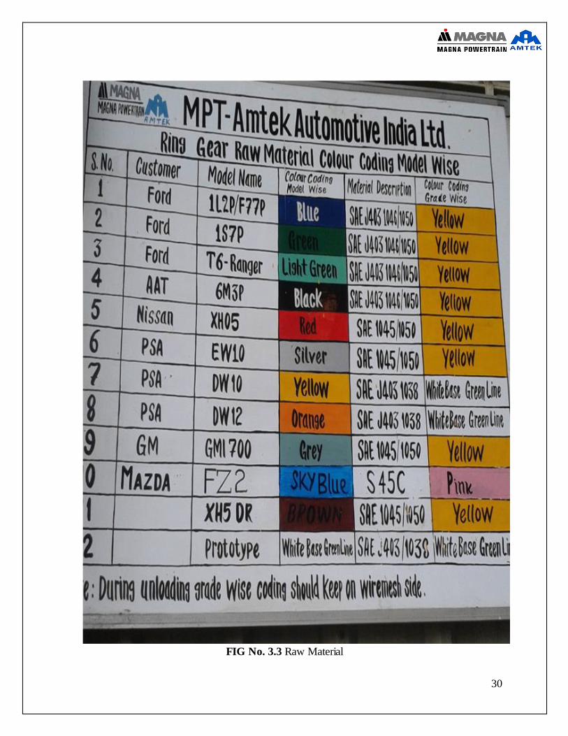
FIG No. 3.3 Raw Material
31
PRODUCTION PROCESS
Ring Gear Manufacturing
1. Blanking: Blanking process the rolling of a straight trapezoidal bar of steel into a coiled form; slitting the entire coil at a point to separate each steel loop of the coil which in the
form of ring but silt at point; flash butt welding together of the separate end of the loop together to form a complete ring; removal of extra welding flash from the ring; tempering
of the welded ring to revealed the stress created in the ring during welding and finally this operation is followed by the shot blasting operation, which is done to remove the scales form during the normalizing operation. After this operation being completed the ring are
press on the hydraulic press to rectify any deformation created during the previous processes. Now the ring is ready for machining.
2. Machining: the machining processes involved is turning. Basically the turning operation on a ring is done in two step. In the first step & the internal diameter is turned to specific
size and surface finish. The cycle time to this operation is varies between 1-1.5 minutes depending on the size of the ring. In the second step outer diameter & outer face is turned
and the cycle time varies between 1 - 1.5
3. Hobbing: The term hobbing is refer to the process of cutting the outer diameter of the machining ring into the shape of gear teeth by a specially designed cutting tool is called
the hob cutter. The profile and the shape of the cutter on the hob. Gera hobbing is performed on special purpose machine called the gear hobber and the fixture on which rings are held during the hobbing process is called the colleted type hobbing fixture which has a highly
intricate design which allow the fixture to contract and expand for the purpose of ring loading and unloading and after hobbing respectively. The cycle time of the operation
varies between 30-45 min.
4. Chamfering: In the chamfering process the sharp edges of the gear teeth on the clutch
side of the gear are removed to facilitate easy engagement of gear teeth with the pinion gear of the electric starter motor of the engine as to avoid any kind of friction, which may
occur otherwise during actual use. The approx. cycle time of the operation is between 50sec -120sec depending on the component.
5. Debarring & washing punching: In the process the loose chips of the metal which may
have stuck of the ring are removed and the gear are washed using antirust oil. This operation take around one minute. Punching of the batch code and the supplier code is alose done after this process.
6. Induction hardening: This is the operation of raising the surface hardness of the gear teeth
up to a specific level and the depth of the hardness is also controlled to achieve a specific case as per the design requirement of the costumer. Immediately after the induction Harding the gear are lowered in the quenching tank which contains any three liquid that is,

32
oil, polymer or water. The cycle time for the operation varies between 20-40sec depending on the size the component and hardness required.
Ring Gear Manufacturing Process
RAW MATERIAL
(Trapizodial Bar Of Alloy Steel)
INWARD INSPECTION
(To Verify The Dimensional And Metallurgical Parameter )
BLANKING
MACHINING
HOBBING
CHAMFERING
WASHING
INDUCTION HARDENING
FINISHED COMPONENT
33
There are several processes on the different machines is involves to produces the ring gear on the
production line. Product and machines have different specification at several processes.
FLOW CHART OF RING GEAR PRODUCTION LINE
RING GEAR PRODUCTION LINE 4
UNIT
RAW MATERIAL (QUALITY
CHECK)
BENDING MACHINE
SLITTING MACHINE
BUTT WELDING MACHINE
TRIMING MACHINE
NORMALIZING
MACHINE
COLD SIZING MACHINE
CNC
MANCHINEQUALITY GATE 1
HOBBING
MACHINE
CHAMFERING MACHINE
PUNCHING
MACHINE
WASHING MACHINE
INDUCTION HARDENING
MACHINE
QUALITY GATE 2
34
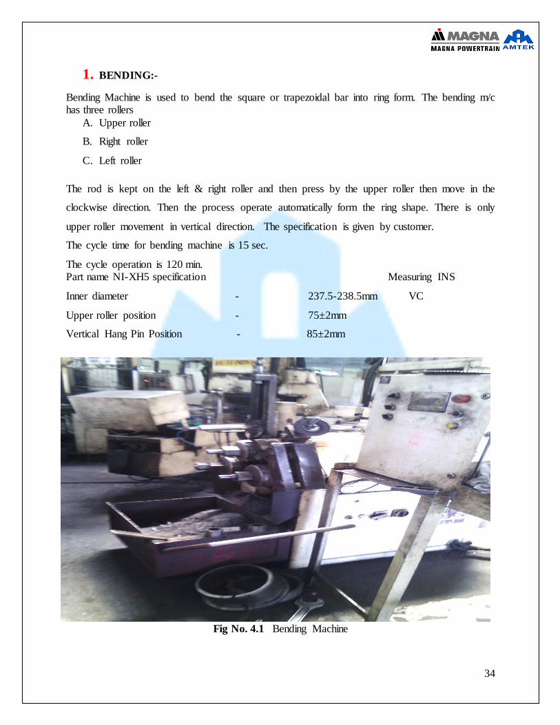
1. BENDING:-
Bending Machine is used to bend the square or trapezoidal bar into ring form. The bending m/c has three rollers
A. Upper roller
B. Right roller
C. Left roller
The rod is kept on the left & right roller and then press by the upper roller then move in the
clockwise direction. Then the process operate automatically form the ring shape. There is only
upper roller movement in vertical direction. The specification is given by customer.
The cycle time for bending machine is 15 sec.
The cycle operation is 120 min. Part name NI-XH5 specification Measuring INS
Inner diameter - 237.5-238.5mm VC
Upper roller position - 75±2mm
Vertical Hang Pin Position - 85±2mm
Fig No. 4.1 Bending Machine

35
Fig No. 4.2 Bending Processes
After the bending processes raw material will be produced as shown in fig
Fig No. 4.3 after Bending

36
OK SAMPLE PRODUCT
Fig No. 4.4
DEFECTIVE PRODUCT
Fig No. 4.5
37
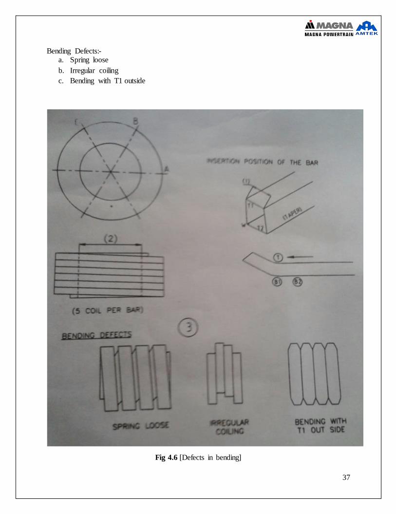
Bending Defects:- a. Spring loose
b. Irregular coiling
c. Bending with T1 outside
Fig 4.6 [Defects in bending]
38
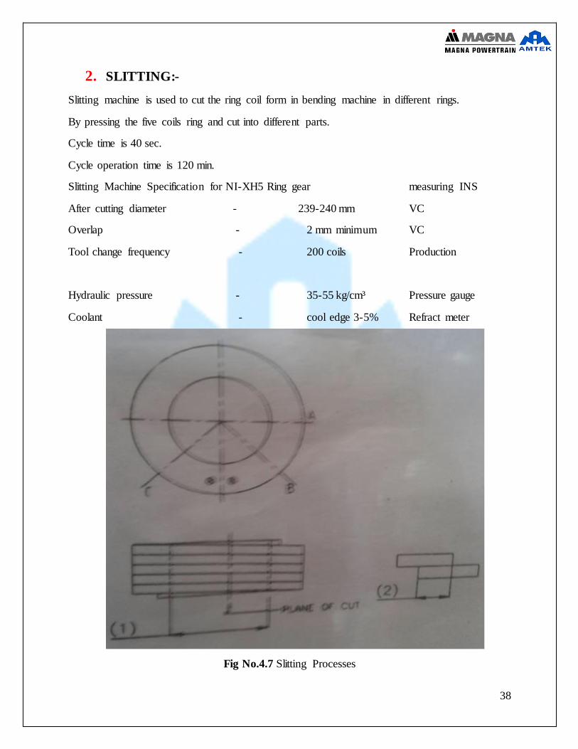
2. SLITTING:-
Slitting machine is used to cut the ring coil form in bending machine in different rings.
By pressing the five coils ring and cut into different parts.
Cycle time is 40 sec.
Cycle operation time is 120 min.
Slitting Machine Specification for NI-XH5 Ring gear measuring INS
After cutting diameter - 239-240 mm VC
Overlap - 2 mm minimum VC
Tool change frequency - 200 coils Production
Hydraulic pressure - 35-55 kg/cm³ Pressure gauge
Coolant - cool edge 3-5% Refract meter
Fig No.4.7 Slitting Processes

39
PRODUCT ON SALTTING
Fig No. 4.8 Slatted product
40
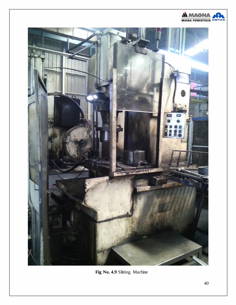
Fig No. 4.9 Slitting Machine

41
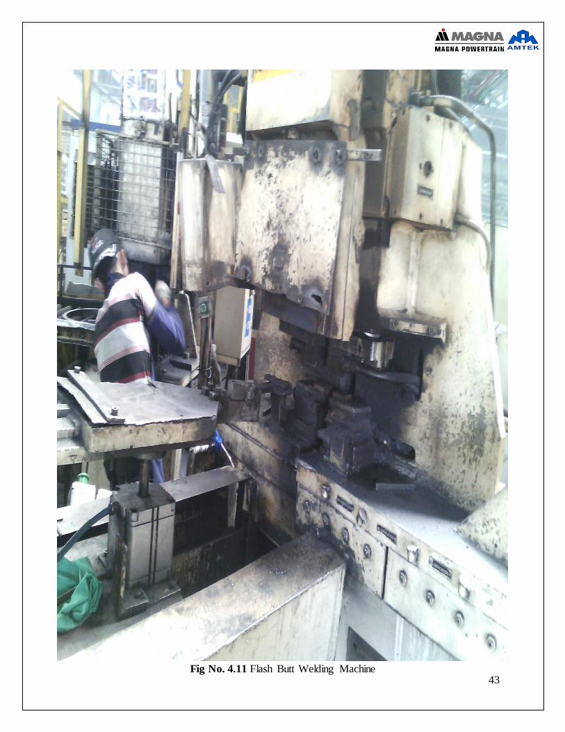
3. FLASH BUTT WELDING & TRIMMING:-
Flash butt welding is a type of resistance welding without using any filler metal. It is used for
joining two metal parts together using heat and force. Each of the two parts to be joined is clamped
against an electrode, usually a copper alloy. The electrodes themselves being connected to the
secondary side of a transformer. The ends are brought slowly together until they just touch. At this
point a high current flows through the touching points, rapidly heating and melting the metal at
the points of contact. The molten metal is then expelled by its own rapid expansion. This part of
the welding cycle is called the flashing and generally creates a spectacular shower of sparks.
Voltage used is generally low (typically between 4 and 20 volts) but the current usually very high,
often in the tens of thousands of amps. The heat generated raises the temperature of either side of
the joint. Once the temperature is above the forging temperature (typically around 1,250°C for
steel) the ends are rapidly pushed together with great force. The high speed expels any remaining
molten metal and the high force generates enough pressure at the joint (around 90 megapascals for
steel) to 'forge weld' the ends together.
THE DIFFERENT CYCLES USED
Pre-Heating
Sometimes an optional pre-heating operation is used to heat the joint area using Joules energy from
passing a current through the joint area directly without any flashing. This heats the whole area
between the electrodes. Pre-heating itself is sometime preceded by a 'Burn off' cycle which
prepares the ends for better contact in the pre-heating cycle.
Flashing Operation
An important parameter is to attain the proper forging temperature around the joint. This is
generally dependent on the amount of heat generated by the flashing cycle. Flashing is typically
determined by either a pre-set amount of time (seconds) or a pre-set distance to be flashed away
(mm). Whereas pre-heating will heat the whole joint area that is between the electrodes, flashing
will instead generate heat only at the joint interface. Heat will then be conducted back into the joint
parent metal.
Butting a.k.a. upsetting
Once the correct temperature profile has been generated then the ends of the joint are rapidly forced
together. Initially a high velocity 'squirts' out any impure molten metal at the joint interface before
it solidifies. Further movement as the joint cools swells the joint area through an upsetting action
until the pressure at the joint, along with the temperature is sufficient to 'forge-weld' the ends
together.
Hold Time
At the end of upsetting there is commonly a 'hold time' during which the joint is held still to allow
the joint to cool and the two pieces of metal to completely bond.

42
Applications I. Railway Lines (Flash butt welding machines are often transported to the work site on
a road-rail vehicle) II. Chains
III. Steel wheels IV. Sheets or rods of steel in rolling mills. V. Starter rings
Fig No. 4.10 Butt Welding Processes
PARTS OF TRIMMING AND BUTT WELDING:-
I. Flash butt welding and trimming machine
II. Top clamp
III. Electrode
IV. Trimming resting pad
V. Trimming bit
VI. Horizontal cassete
VII. Vertical cassete
43
Fig No. 4.11 Flash Butt Welding Machine

44
PRODUCT AND MACHINE SPECIFICATION
Specification for NI-XH5 Part
Internal Diameter - 237-238 mm
Welding strength - 542 Nmm² minimum
Ovality - 2 mm max without weld area
Trimming depth on both faces - 0.3 mm max
Trimming depth on ID - 0.3 mm max
Trimming depth on OD - 0.3 mm max
Electrode change after - 1500 pcs
Welding start position - 40±5 mm
Fleshing length - 4±1 mm
Butting length - 4±1 mm
Preheat - off
Free heat pressure - 0
Free heat count - 0.0
Initial fleshing velocity - 3.7±0.20 mm/sec
Initial current feedback - 2.0±0.20 amp
Acceleration - 4.0±1 mm/ sec²
Butting hold time - 1.2±20 sec
Fleshing time - 2±0.50 sec
Clamping pressure - 40±5 kg/cm²
Butting pressure - 30±5 kg/cm²
45
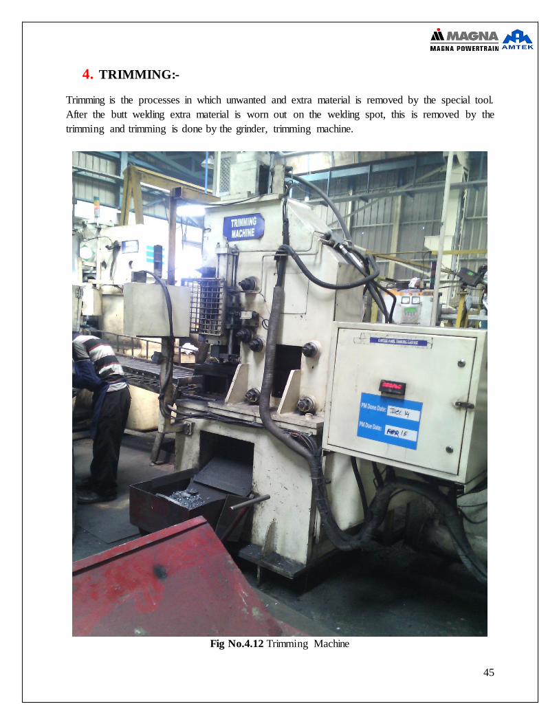
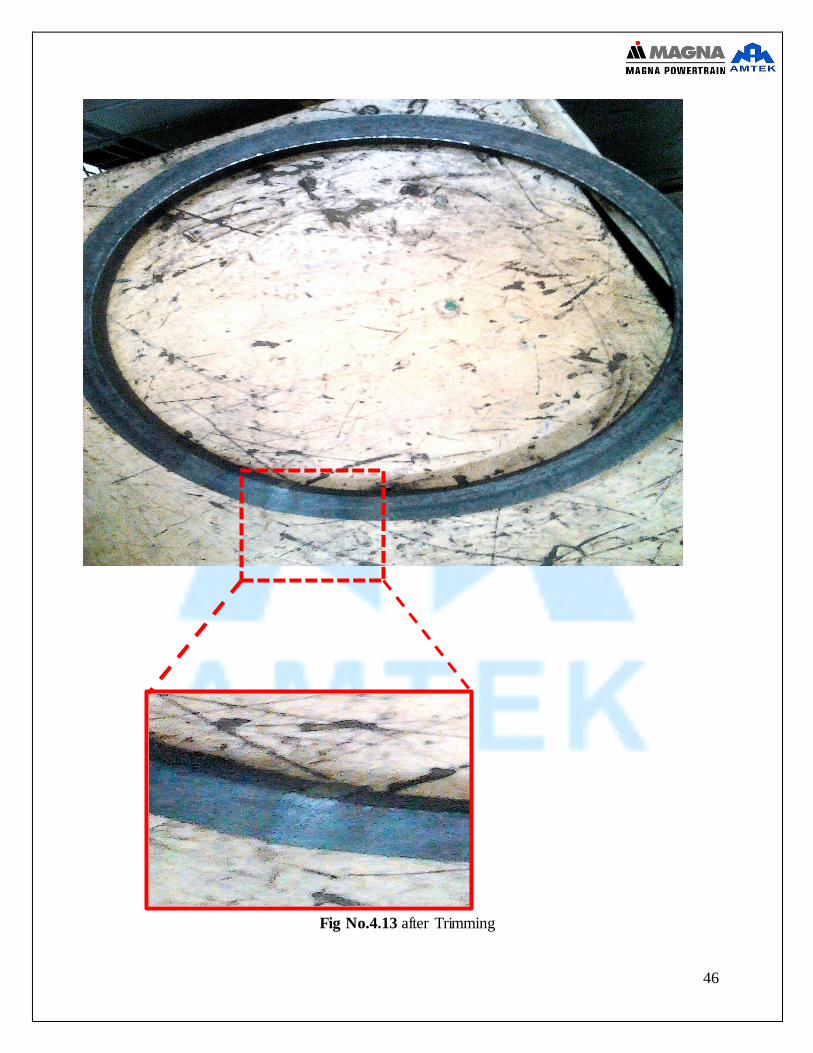
4. TRIMMING:-
Trimming is the processes in which unwanted and extra material is removed by the special tool.
After the butt welding extra material is worn out on the welding spot, this is removed by the
trimming and trimming is done by the grinder, trimming machine.
Fig No.4.12 Trimming Machine
46
Fig No.4.13 after Trimming

47
5. NORMALIZING:-
Importance of Normalizing
A necessary first step in the heat treatment process involves "normalizing," a process
designed to present a homogenous microstructure to the carburizing process. To reduce
overall part distortion, it is highly undesirable to have this homogenization take place during
the carburizing cycle of a finished gear component. A separate normalizing cycle removes
the problems associated with pearlite and ferrite segregation. Ferritic areas do not transform
to the same hardness and stress levels as pearlitic areas when homogenized during the
carburizing cycle, resulting in more--not less--distortion.
Normalizing is a process that involves heating a part above the upper critical temperature and
then typically air cooling outside the furnace to relieve residual stresses in a gear blank and to
aid dimensional stability. Normalizing is often considered from both a thermal and
microstructural standpoint. In the thermal sense, normalizing is austenitizing followed by
cooling in still or slightly agitated air or nitrogen. In a microstructural sense, the areas of the
microstructure that contain about 0.8 % carbon are pearlitic, while the areas of low carbon
are ferrite. A normalized part is very machinable but harder than an annealed part. It also
relieves any residual stresses present from the steel making and forging processes that could
cause later distortion during carburizing.
A good normalizing cycle consists of holding the rough material "at temperature" for two
hours minimum, or one hour per inch of section thickness. The temperature should be the
same or higher than the carburizing temperature later used
PRODUCT AND MACHINE SPECIFICATION
Hardness - 85-95 HRB Grain size - 5-8 ASTM
Micro structure - normalized structure Uniformly distributed ferrite with pearlite
Power level - 24%-28% Heating time - 20-25 sec Min temperature - 800 ·c
Max temperature - 890 ·c
48
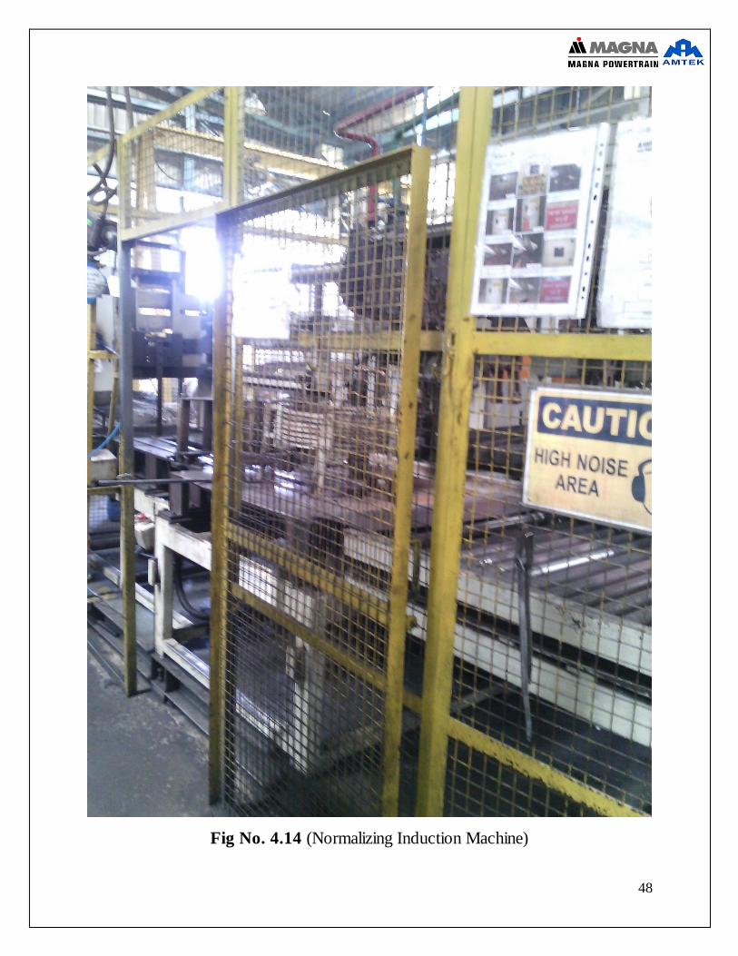
Fig No. 4.14 (Normalizing Induction Machine)

49
Fig No. 4.15 (Normalizing Induction Coil)
Product at the Normalizing Processes
Fig No. 4.16 Normalizing Ring Gear

50
6. COLD SIZING:-
Cold sizing is a squeezing operation performed at temperatures significantly below the melting
point to finish the surface of a work piece to ensure better dimensional accuracy and surface
finish.
The sizing operation is a squeezing operation that minimizes the thickness of the metal. Sizing
is performed in an open die and only the surface where the die and work piece touch will be
sized. Many ferrous metal castings are sized to sharpen corners and flatten holes around
piercings. Sizing pressure is determined by area to be sized, the metal used, and the change in
metal thickness from the operation. Sizing is usually performed on semi-finished parts or parts
that require an accurate finish. Stop blocks are used to ensure close tolerances.
Cold sizing, like all other cold forming processes, has a hot process counterpart. In addition to
semi-finished parts, cold forming may be used on metal stock, sheet, bar, and rod stock. Cold
sizing can be performed on various metals, both ferrous and non-ferrous, and even materials
like polymers and plastics. Sizing is related to other squeezing operations like swaging,
coining, hobbing, staking and riveting, thread rolling, and extruding.
Although the whole work piece may be inserted into the die, the sizing operation can give
dimensional accuracy to a portion of the part based on the contact with the die. Sizing is mostly
used to give a forged or cast part better dimensional accuracy. Mated surfaces between
touching parts like gears are often sized. The sizing operation also provides a better surface
hardness and finish to the work piece. Also, the sized surface of the work piece gets denser and
stronger when the operation is performed. The dimensional tolerance of the operation is about
0.025 millimetres (0.00098 in). Primary pressing or a compacting die are typically used when
sizing small batches of compact. To keep costs down, larger batches of compact usually have
a specialized die made specifically for the operation.
Parts of cold sizing machine
Press machine and Core bar

51
Fig No. 4.17 Cold Sizing Machine
52
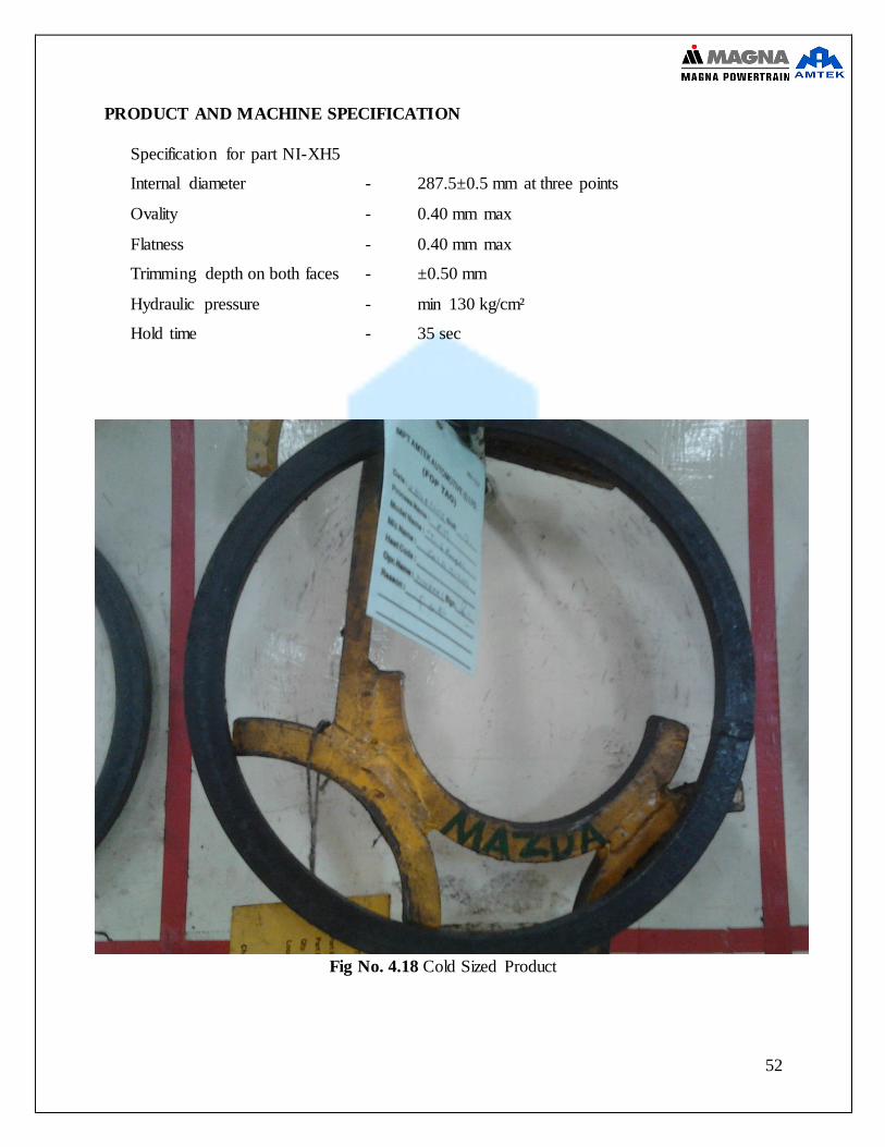
PRODUCT AND MACHINE SPECIFICATION
Specification for part NI-XH5
Internal diameter - 287.5±0.5 mm at three points
Ovality - 0.40 mm max
Flatness - 0.40 mm max
Trimming depth on both faces - ±0.50 mm
Hydraulic pressure - min 130 kg/cm²
Hold time - 35 sec
Fig No. 4.18 Cold Sized Product
53
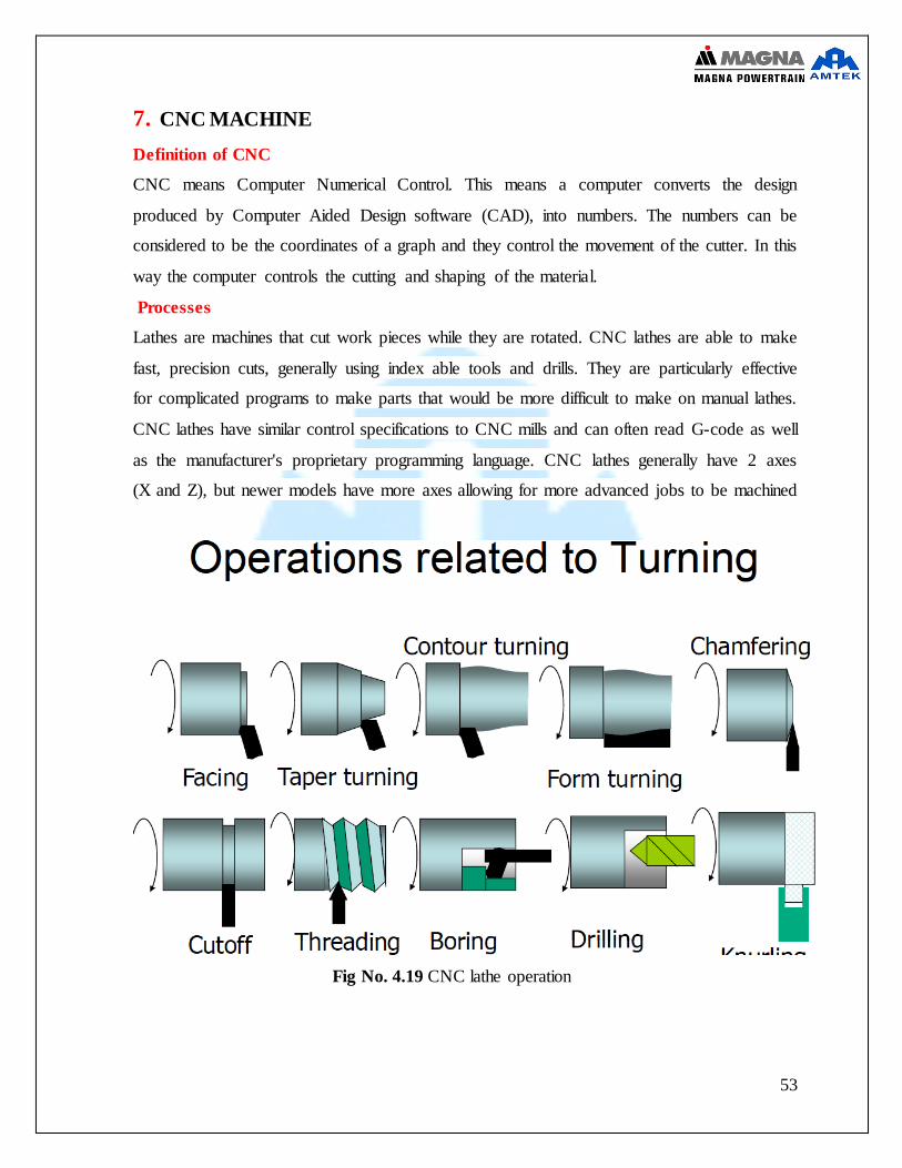
7. CNC MACHINE
Definition of CNC
CNC means Computer Numerical Control. This means a computer converts the design
produced by Computer Aided Design software (CAD), into numbers. The numbers can be
considered to be the coordinates of a graph and they control the movement of the cutter. In this
way the computer controls the cutting and shaping of the material.
Processes
Lathes are machines that cut work pieces while they are rotated. CNC lathes are able to make
fast, precision cuts, generally using index able tools and drills. They are particularly effective
for complicated programs to make parts that would be more difficult to make on manual lathes.
CNC lathes have similar control specifications to CNC mills and can often read G-code as well
as the manufacturer's proprietary programming language. CNC lathes generally have 2 axes
(X and Z), but newer models have more axes allowing for more advanced jobs to be machined
Fig No. 4.19 CNC lathe operation

54
Fig No. 4.20 CNC lathe machine
ADVANTAGES 1. CNC machines are programmed with a design which can then be manufactured hundreds
or even thousands of times. Each manufactured product will be exactly the same.
2. CNC machines can be updated by improving the software used to drive the machines
3. Less skilled/trained people can operate CNCs unlike manual lathes / milling machines etc.
which need skilled engineers
4. CNC machines can be used continuously 24 hours a day, 365 days a year and only need to
be switched off for occasional maintenance.
5. CNC machines can be programmed by advanced design software such as Pro/DESKTOP®,
enabling the manufacture of products that cannot be made by manual machines, even those
used by skilled designers / engineers.
55
6. Modern design software allows the designer to simulate the manufacture of
his/her idea. There is no need to make a prototype or a model. This saves time
and money
DISADVANTAGES
1. CNC machines are more expensive than manually operated machines, although costs are
slowly coming down.
2. The CNC machine operator only needs basic training and skills, enough to supervise
several machines. In years gone by, engineers needed years of training to operate Centre
lathes, milling machines and other manually operated machines. This means many of the
old skills are been lost.
3. Less workers are required to operate CNC machines compared to manually operated
machines. Investment in CNC machines can lead to unemployment
4. Many countries no longer teach pupils / students how to use manually operated lathes /
milling machines etc... Pupils / students no longer develop the detailed skills required by
engineers of the past. These include mathematical and engineering skills
APPLICATION 1. Industries for Fabricating Metals
2. Electrical Discharge Machining (EDM) Industry
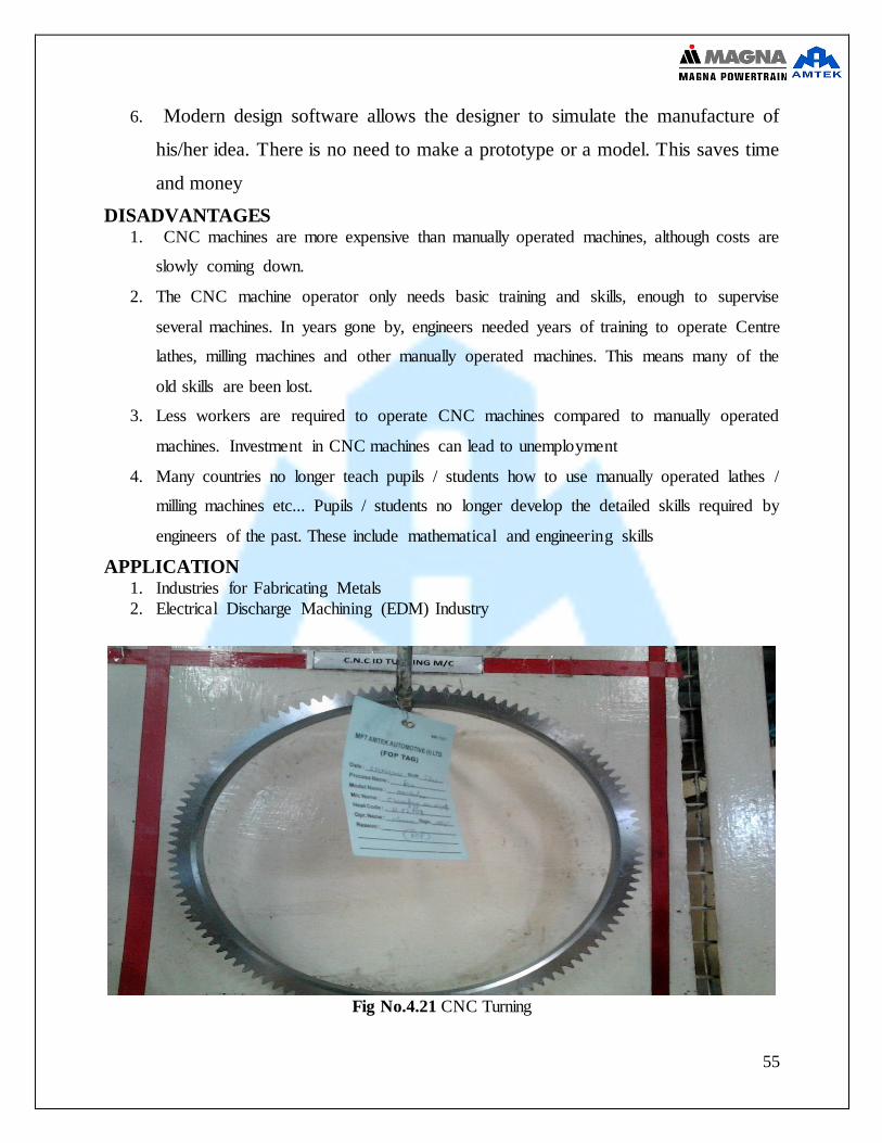
Fig No.4.21 CNC Turning
56
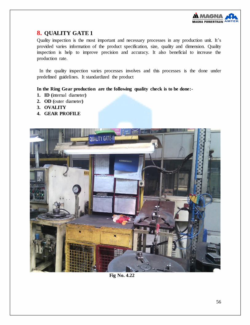
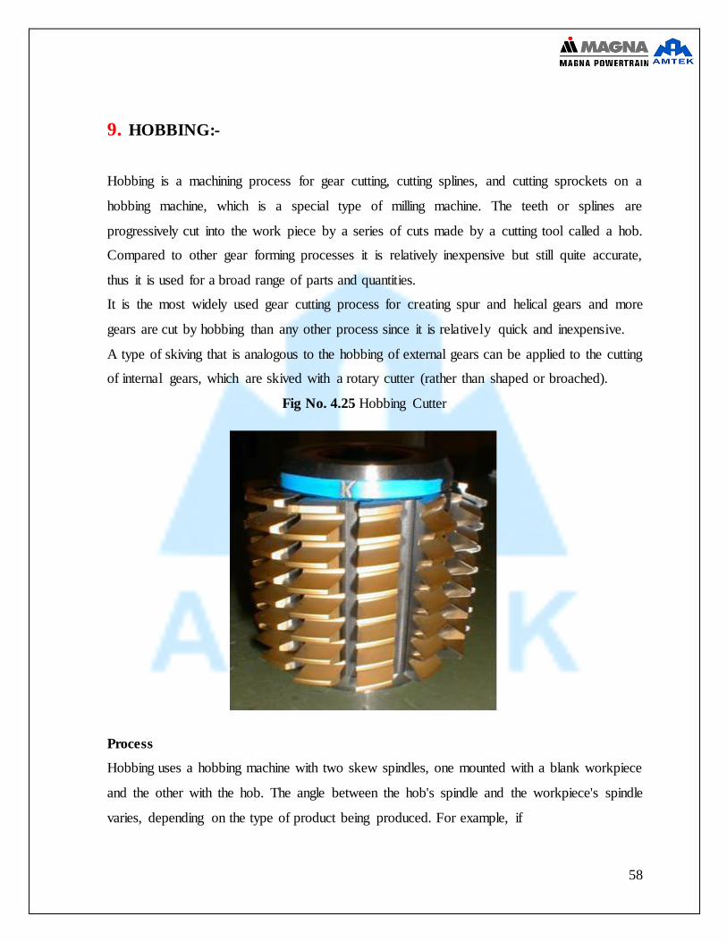
8. QUALITY GATE 1
Quality inspection is the most important and necessary processes in any production unit. It’s
provided varies information of the product specification, size, quality and dimension. Quality
inspection is help to improve precision and accuracy. It also beneficial to increase the
production rate.
In the quality inspection varies processes involves and this processes is the done under
predefined guidelines. It standardized the product
In the Ring Gear production are the following quality check is to be done:-
1. ID (internal diameter)
2. OD (outer diameter)
3. OVALITY
4. GEAR PROFILE
Fig No. 4.22
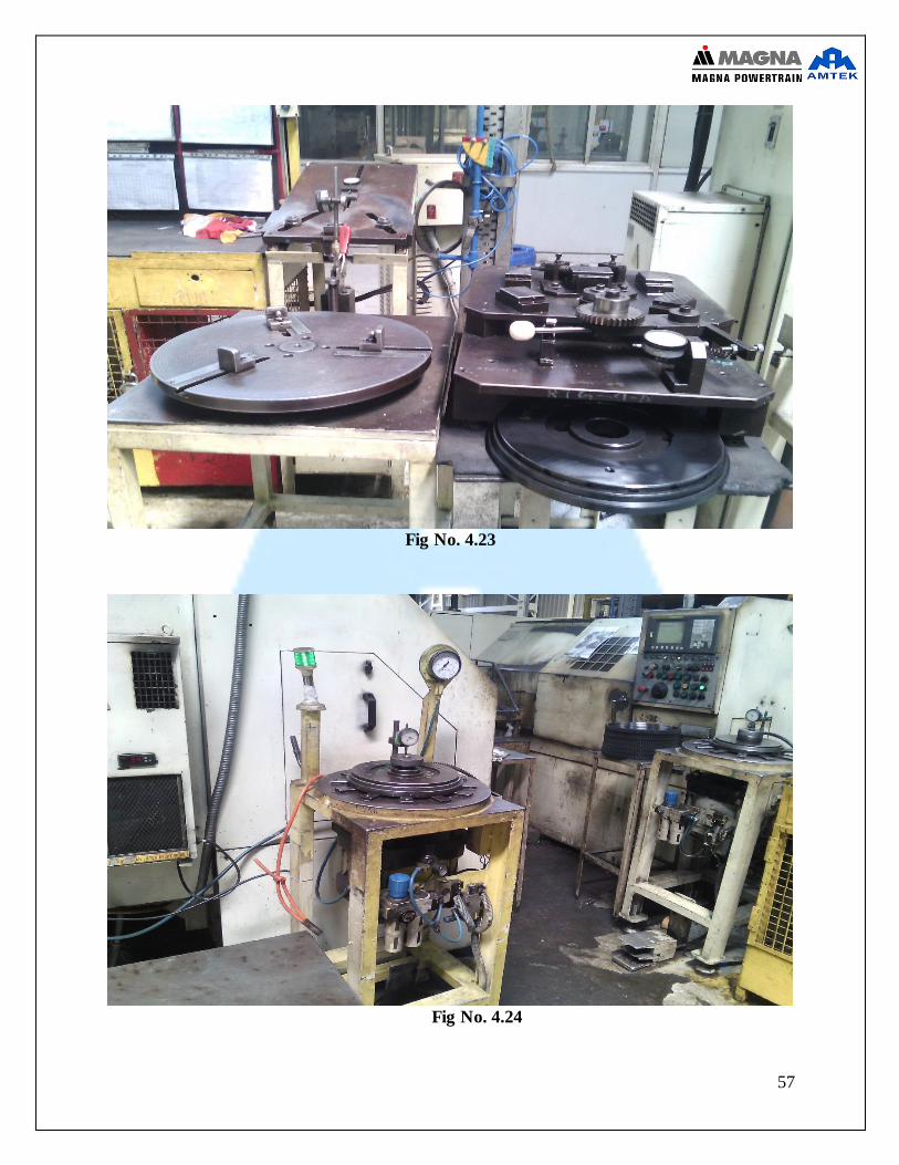
57
Fig No. 4.23
Fig No. 4.24
58
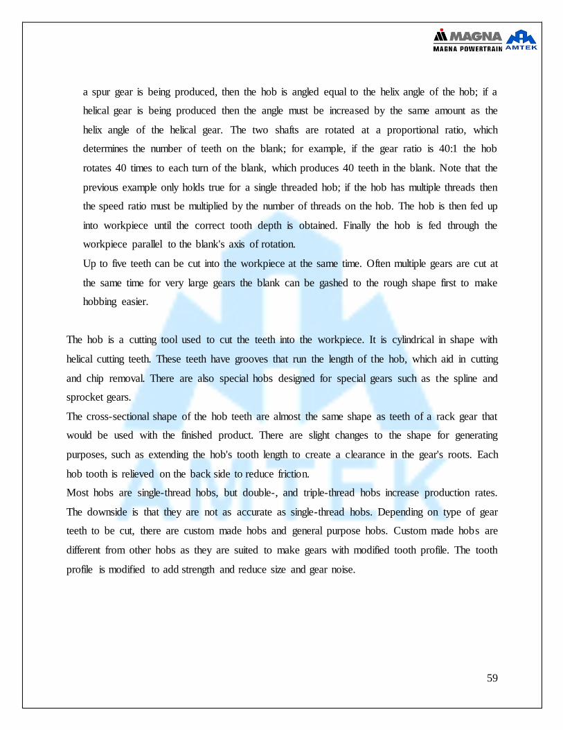
9. HOBBING:-
Hobbing is a machining process for gear cutting, cutting splines, and cutting sprockets on a
hobbing machine, which is a special type of milling machine. The teeth or splines are
progressively cut into the work piece by a series of cuts made by a cutting tool called a hob.
Compared to other gear forming processes it is relatively inexpensive but still quite accurate,
thus it is used for a broad range of parts and quantities.
It is the most widely used gear cutting process for creating spur and helical gears and more
gears are cut by hobbing than any other process since it is relatively quick and inexpensive.
A type of skiving that is analogous to the hobbing of external gears can be applied to the cutting
of internal gears, which are skived with a rotary cutter (rather than shaped or broached).
Fig No. 4.25 Hobbing Cutter
Process
Hobbing uses a hobbing machine with two skew spindles, one mounted with a blank workpiece
and the other with the hob. The angle between the hob's spindle and the workpiece's spindle
varies, depending on the type of product being produced. For example, if
59
a spur gear is being produced, then the hob is angled equal to the helix angle of the hob; if a
helical gear is being produced then the angle must be increased by the same amount as the
helix angle of the helical gear. The two shafts are rotated at a proportional ratio, which
determines the number of teeth on the blank; for example, if the gear ratio is 40:1 the hob
rotates 40 times to each turn of the blank, which produces 40 teeth in the blank. Note that the
previous example only holds true for a single threaded hob; if the hob has multiple threads then
the speed ratio must be multiplied by the number of threads on the hob. The hob is then fed up
into workpiece until the correct tooth depth is obtained. Finally the hob is fed through the
workpiece parallel to the blank's axis of rotation.
Up to five teeth can be cut into the workpiece at the same time. Often multiple gears are cut at
the same time for very large gears the blank can be gashed to the rough shape first to make
hobbing easier.
The hob is a cutting tool used to cut the teeth into the workpiece. It is cylindrical in shape with
helical cutting teeth. These teeth have grooves that run the length of the hob, which aid in cutting
and chip removal. There are also special hobs designed for special gears such as the spline and
sprocket gears.
The cross-sectional shape of the hob teeth are almost the same shape as teeth of a rack gear that
would be used with the finished product. There are slight changes to the shape for generating
purposes, such as extending the hob's tooth length to create a clearance in the gear's roots. Each
hob tooth is relieved on the back side to reduce friction.
Most hobs are single-thread hobs, but double-, and triple-thread hobs increase production rates.
The downside is that they are not as accurate as single-thread hobs. Depending on type of gear
teeth to be cut, there are custom made hobs and general purpose hobs. Custom made hobs are
different from other hobs as they are suited to make gears with modified tooth profile. The tooth
profile is modified to add strength and reduce size and gear noise.
60
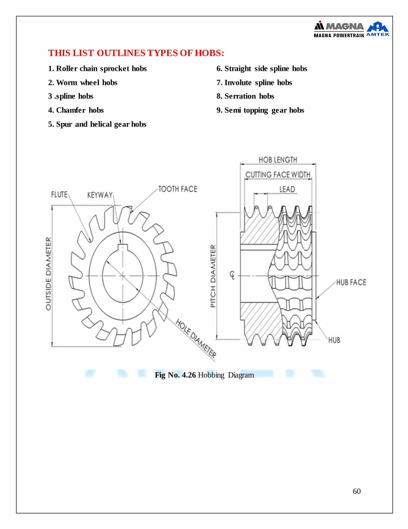
THIS LIST OUTLINES TYPES OF HOBS:
1. Roller chain sprocket hobs
2. Worm wheel hobs
3 .spline hobs
4. Chamfer hobs
5. Spur and helical gear hobs
6. Straight side spline hobs
7. Involute spline hobs
8. Serration hobs
9. Semi topping gear hobs
Fig No. 4.26 Hobbing Diagram

61
Fig No. 4.27 HOBBING MACHINE

62
PRODUCT AND MACHINE SPECIFICATION
Specification for part Mazda fz2 Measurement of teeth over 14 teeth - 105.39±0.07 mm
MOT variation - 0.10 max Root diameter - 291.95±0.10 mm Gear profile - deflection should not be more than
0.35 mm on dial indicator No. of teeth - 117
Hobb cutter specification Clamping pressure - 30-40 kg/cm²
Axial feed - 1.4-1.9 mm Hob run out - 0.05 max
Fixture run out - 0.04 max RPM of hob - 100-150 Stack height - 11 nos
Fig No. 4.28 after hobbing processes
63
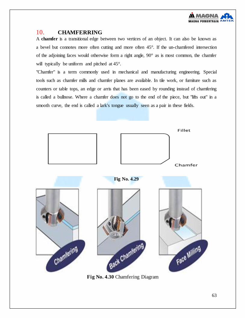
10. CHAMFERRING A chamfer is a transitional edge between two vertices of an object. It can also be known as
a bevel but connotes more often cutting and more often 45°. If the un-chamfered intersection
of the adjoining faces would otherwise form a right angle, 90° as is most common, the chamfer
will typically be uniform and pitched at 45°.
"Chamfer" is a term commonly used in mechanical and manufacturing engineering. Special
tools such as chamfer mills and chamfer planes are available. In tile work, or furniture such as
counters or table tops, an edge or arris that has been eased by rounding instead of chamfering
is called a bullnose. Where a chamfer does not go to the end of the piece, but "lifts out" in a
smooth curve, the end is called a lark's tongue usually seen as a pair in these fields.
Fig No. 4.29
Fig No. 4.30 Chamfering Diagram
64
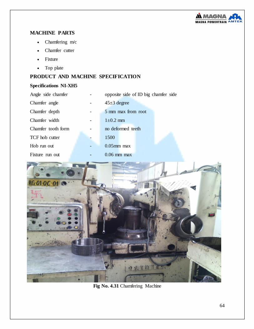
MACHINE PARTS
Chamfering m/c
Chamfer cutter
Fixture
Top plate
PRODUCT AND MACHINE SPECIFICATION
Specifications NI-XH5
Angle side chamfer - opposite side of ID big chamfer side
Chamfer angle - 45±3 degree
Chamfer depth - 5 mm max from root
Chamfer width - 1±0.2 mm
Chamfer tooth form - no deformed teeth
TCF hob cutter - 1500
Hob run out - 0.05mm max
Fixture run out - 0.06 mm max
Fig No. 4.31 Chamfering Machine

65
Ring gear after the chamfering processes
Fig No. 4.32 Chamfered Product
Chamfering is not done all the model of the ring gear

66
11. PUNCHING AND WASHING
Punching:-
Punching is a metal forming process that uses a punch press to force a tool, called a punch,
through the work piece to create a hole via shearing. The punch often passes through the work
into a die. A scrap slug from the hole is deposited into the die in the process
This is use to punch the batch/lot number on face of ring gear.
WASHING:-
Washing is basically an industrial bath. In this processes ring gear is washed out the industrial
chemical which remove the unwanted material and provide a protection layer to ring gear from
the corrosion.
Fig No. 4.33 Washing Machine
67
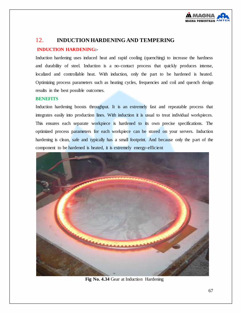
12. INDUCTION HARDENING AND TEMPERING
INDUCTION HARDENING:-
Induction hardening uses induced heat and rapid cooling (quenching) to increase the hardness
and durability of steel. Induction is a no-contact process that quickly produces intense,
localized and controllable heat. With induction, only the part to be hardened is heated.
Optimizing process parameters such as heating cycles, frequencies and coil and quench design
results in the best possible outcomes.
BENEFITS
Induction hardening boosts throughput. It is an extremely fast and repeatable process that
integrates easily into production lines. With induction it is usual to treat individual workpieces.
This ensures each separate workpiece is hardened to its own precise specifications. The
optimized process parameters for each workpiece can be stored on your servers. Induction
hardening is clean, safe and typically has a small footprint. And because only the part of the
component to be hardened is heated, it is extremely energy-efficient
Fig No. 4.34 Gear at Induction Hardening

68
TEMPERING:-
Induction tempering is a heating process that optimizes mechanical properties such as
toughness and ductility in workpieces that have already been hardened.
BENEFITS
The main advantage of induction over furnace tempering is speed. Induction can temper
workpieces in minutes, sometimes even seconds. Furnaces typically take hours. And as
induction tempering is perfect for inline integration, it minimizes the number of components
in process. Induction tempering facilitates quality control of individual workpieces. Integrated
induction temper stations also save valuable floor space.
Fig No. 4.35 Gear at Induction Tempering

69
PARTS OF THE MACHINE
Induction hardening and tempering machine
Hardening fixture
Tempering block
Tempering coil
Fig No. 4.36 Induction Hardening and Tempering Machine
70
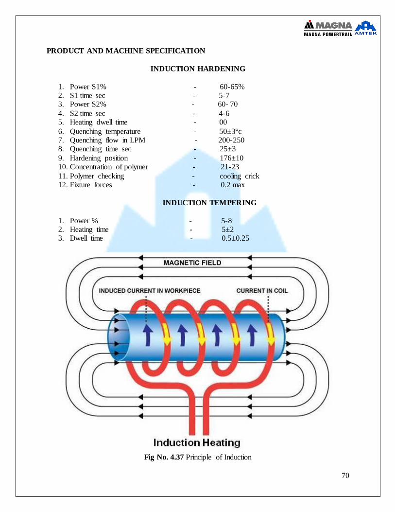
PRODUCT AND MACHINE SPECIFICATION
INDUCTION HARDENING
1. Power S1% - 60-65% 2. S1 time sec - 5-7 3. Power S2% - 60- 70
4. S2 time sec - 4-6 5. Heating dwell time - 00
6. Quenching temperature - 50±3°c 7. Quenching flow in LPM - 200-250 8. Quenching time sec - 25±3
9. Hardening position - 176±10 10. Concentration of polymer - 21-23
11. Polymer checking - cooling crick 12. Fixture forces - 0.2 max
INDUCTION TEMPERING
1. Power % - 5-8 2. Heating time - 5±2 3. Dwell time - 0.5±0.25
Fig No. 4.37 Principle of Induction

71
13. QUALITY GATE 2 Quality control, or QC for short, is a process by which entities review the quality of all
factors involved in production. ISO 9000 defines quality control as "A part of quality management focused on fulfilling quality requirements"
This approach places an emphasis on three aspects
1. Elements such as controls, job management, defined and well managed processes, performance and integrity criteria, and identification of records
2. Competence, such as knowledge, skills, experience, and qualifications 3. Soft elements, such as personnel, integrity, confidence, organizational
culture, motivation, team spirit, and quality relationships.
Controls include product inspection, where every product is examined visually, and often using a stereo microscope for fine detail before the product is sold into the external market.
Inspectors will be provided with lists and descriptions of unacceptable product defects such as cracks or surface blemishes for example. .
Fig No. 4.38

72
Fig No. 4.39

73