an 846: intel® stratix® 10 forward error correction · figure 1. types of codes ecc codes block...
TRANSCRIPT
AN 846: Intel® Stratix® 10 ForwardError Correction
SubscribeSend Feedback
AN-846 | 2018.07.02Latest document on the web: PDF | HTML
Contents
1. Introduction................................................................................................................... 4
2. Necessity of Error Correction.......................................................................................... 52.1. Solutions to Transmission Errors.............................................................................. 5
2.1.1. Parity and Cyclic Redundancy Check.............................................................52.1.2. Error Correction Code (ECC) Block Coding.....................................................5
2.2. Error Correction Codes........................................................................................... 62.3. What is FEC?.........................................................................................................6
2.3.1. FEC Definitions..........................................................................................7
3. FEC Selection.................................................................................................................. 83.1. Key Considerations when Choosing a FEC..................................................................8
4. FEC in Intel Stratix 10 H-Tile Devices............................................................................104.1. Fire Code (802.3ap, 10GBASE-KR)......................................................................... 10
4.1.1. FEC Block Format.....................................................................................104.1.2. FEC Block Composition............................................................................. 114.1.3. FEC Sublayer for BASE-R PHYs...................................................................124.1.4. L-Tile/H-Tile Implementation......................................................................13
5. FEC in Intel Stratix 10 E-Tile Devices............................................................................ 155.1. Types of RS-FEC.................................................................................................. 15
5.1.1. RS (528, 514, t = 7, m = 10).................................................................... 165.1.2. RS (544, 514, t = 15, m = 10).................................................................. 185.1.3. Supported RS-FEC Modes in E-Tile Devices.................................................. 19
5.2. 100GBASE-KR4................................................................................................... 205.2.1. 100GBASE-KR4 Mapping (IEEE802.3bj Clause 91)........................................22
5.3. 100GBASE-KP4....................................................................................................225.3.1. 100GBASE-KP4 Mapping (IEEE802.3bj Clause 91)........................................ 23
5.4. FEC Decoders......................................................................................................235.5. Specifications...................................................................................................... 245.6. Functions Within the RS-FEC Sublayer.................................................................... 25
5.6.1. Lane Block Synchronization....................................................................... 255.6.2. Alignment Lock and Deskew...................................................................... 265.6.3. Lane Re-order......................................................................................... 265.6.4. Alignment Marker Removal........................................................................265.6.5. 64B/66B to 256B/257B Transcoder.............................................................26
6. FEC Implementation Using the E-Tile Channel Placement Tool......................................28
7. FEC in Practical Application...........................................................................................307.1. Datacenter Applications Scenario........................................................................... 30
8. Hardware Results......................................................................................................... 328.1. Test Design.........................................................................................................328.2. Test Setup.......................................................................................................... 328.3. Insertion Loss Plots..............................................................................................348.4. FEC Statistics Tool................................................................................................358.5. Hardware Data.................................................................................................... 35
Contents
AN 846: Intel® Stratix® 10 Forward Error Correction2
8.6. Comparison to the Specification.............................................................................368.7. References..........................................................................................................37
9. Document Revision History for AN 846: Intel Stratix 10 Forward Error Correction....... 38
Contents
AN 846: Intel® Stratix® 10 Forward Error Correction3
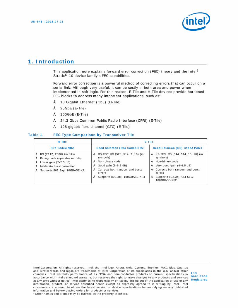
1. IntroductionThis application note explains forward error correction (FEC) theory and the Intel®Stratix® 10 device family's FEC capabilities.
Forward error correction is a powerful method of correcting errors that can occur on aserial link. Although very useful, it can be costly in both area and power whenimplemented in soft logic. For this reason, E-Tile and H-Tile devices provide hardenedFEC blocks to address many important applications, such as:
• 10 Gigabit Ethernet (GbE) (H-Tile)
• 25GbE (E-Tile)
• 100GbE (E-Tile)
• 24.3 Gbps Common Public Radio Interface (CPRI) (E-Tile)
• 128 gigabit fibre channel (GFC) (E-Tile)
Table 1. FEC Type Comparison by Transceiver Tile
H-Tile E-Tile
Fire Code—NRZ Reed Solomon (RS) Code—NRZ Reed Solomon (RS) Code—PAM4
• RS (2112, 2080) (in bits)• Binary code (operates on bits)• Lower gain (2-2.5 dB)• Moderate burst correction• Supports 802.3ap, 10GBASE-KR
• RS-FEC: RS (528, 514, 7 ,10) (insymbols)
• Non-binary code• Good gain (5-5.5 dB)• Corrects both random and burst
errors• Supports 802.3bj, 100GBASE-KR4
• KP-FEC: RS (544, 514, 15, 10) (insymbols)
• Non-binary code• Very good gain (6-6.5 dB)• Corrects both random and burst
errors• Supports 802.3bj, CEI 56G,
100GBASE-KP2
AN-846 | 2018.07.02
Intel Corporation. All rights reserved. Intel, the Intel logo, Altera, Arria, Cyclone, Enpirion, MAX, Nios, Quartusand Stratix words and logos are trademarks of Intel Corporation or its subsidiaries in the U.S. and/or othercountries. Intel warrants performance of its FPGA and semiconductor products to current specifications inaccordance with Intel's standard warranty, but reserves the right to make changes to any products and servicesat any time without notice. Intel assumes no responsibility or liability arising out of the application or use of anyinformation, product, or service described herein except as expressly agreed to in writing by Intel. Intelcustomers are advised to obtain the latest version of device specifications before relying on any publishedinformation and before placing orders for products or services.*Other names and brands may be claimed as the property of others.
ISO9001:2008Registered
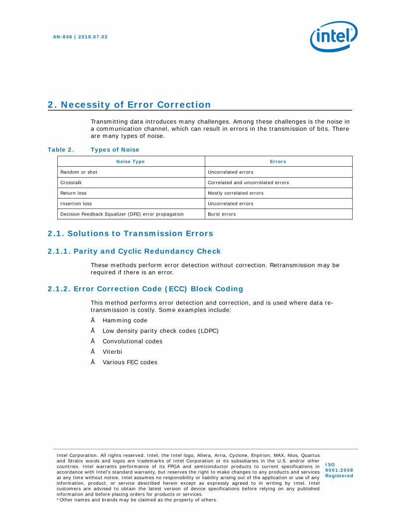
2. Necessity of Error CorrectionTransmitting data introduces many challenges. Among these challenges is the noise ina communication channel, which can result in errors in the transmission of bits. Thereare many types of noise.
Table 2. Types of Noise
Noise Type Errors
Random or shot Uncorrelated errors
Crosstalk Correlated and uncorrelated errors
Return loss Mostly correlated errors
Insertion loss Uncorrelated errors
Decision Feedback Equalizer (DFE) error propagation Burst errors
2.1. Solutions to Transmission Errors
2.1.1. Parity and Cyclic Redundancy Check
These methods perform error detection without correction. Retransmission may berequired if there is an error.
2.1.2. Error Correction Code (ECC) Block Coding
This method performs error detection and correction, and is used where data re-transmission is costly. Some examples include:
• Hamming code
• Low density parity check codes (LDPC)
• Convolutional codes
• Viterbi
• Various FEC codes
AN-846 | 2018.07.02
Intel Corporation. All rights reserved. Intel, the Intel logo, Altera, Arria, Cyclone, Enpirion, MAX, Nios, Quartusand Stratix words and logos are trademarks of Intel Corporation or its subsidiaries in the U.S. and/or othercountries. Intel warrants performance of its FPGA and semiconductor products to current specifications inaccordance with Intel's standard warranty, but reserves the right to make changes to any products and servicesat any time without notice. Intel assumes no responsibility or liability arising out of the application or use of anyinformation, product, or service described herein except as expressly agreed to in writing by Intel. Intelcustomers are advised to obtain the latest version of device specifications before relying on any publishedinformation and before placing orders for products or services.*Other names and brands may be claimed as the property of others.
ISO9001:2008Registered
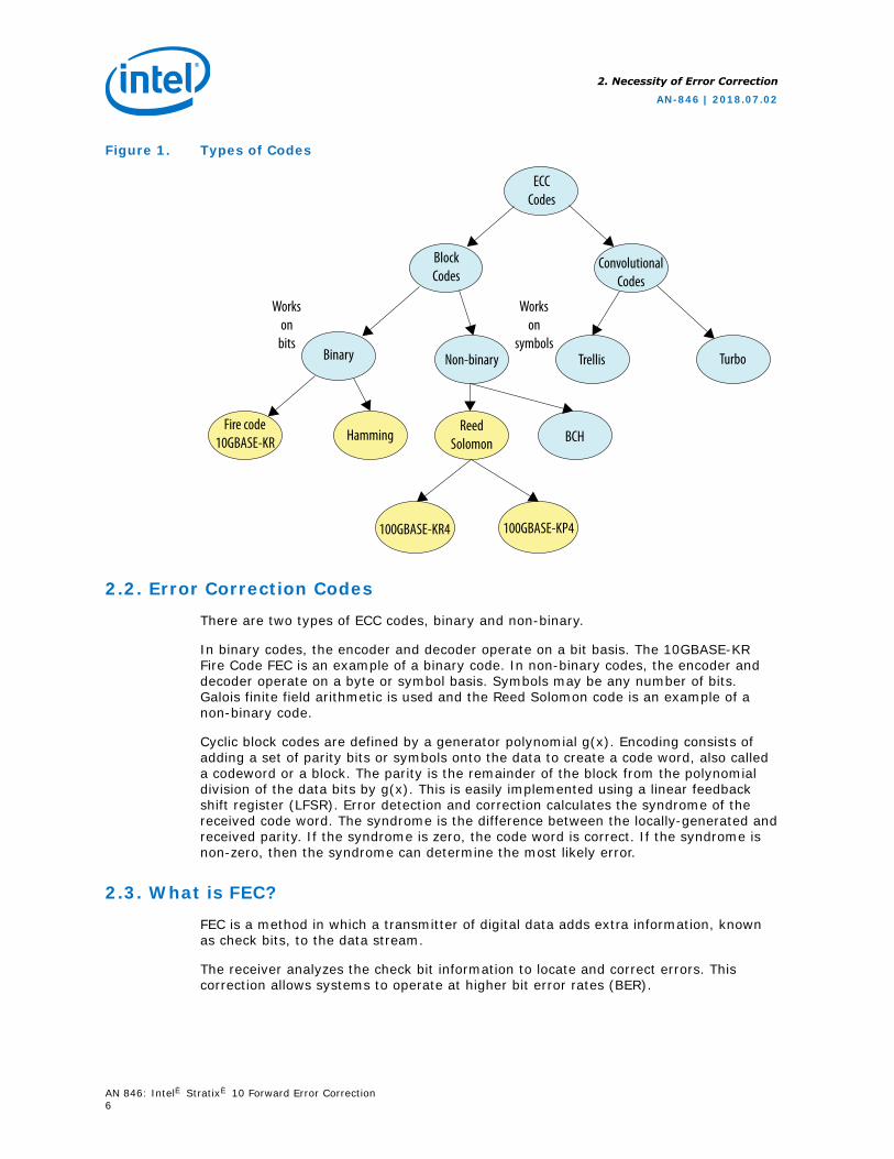
Figure 1. Types of Codes
ECCCodes
BlockCodes
ConvolutionalCodes
Binary Non-binary TurboTrellis
Fire code10GBASE-KR Hamming
ReedSolomon
100GBASE-KR4 100GBASE-KP4
BCH
Workson
bits
Workson
symbols
2.2. Error Correction Codes
There are two types of ECC codes, binary and non-binary.
In binary codes, the encoder and decoder operate on a bit basis. The 10GBASE-KRFire Code FEC is an example of a binary code. In non-binary codes, the encoder anddecoder operate on a byte or symbol basis. Symbols may be any number of bits.Galois finite field arithmetic is used and the Reed Solomon code is an example of anon-binary code.
Cyclic block codes are defined by a generator polynomial g(x). Encoding consists ofadding a set of parity bits or symbols onto the data to create a code word, also calleda codeword or a block. The parity is the remainder of the block from the polynomialdivision of the data bits by g(x). This is easily implemented using a linear feedbackshift register (LFSR). Error detection and correction calculates the syndrome of thereceived code word. The syndrome is the difference between the locally-generated andreceived parity. If the syndrome is zero, the code word is correct. If the syndrome isnon-zero, then the syndrome can determine the most likely error.
2.3. What is FEC?
FEC is a method in which a transmitter of digital data adds extra information, knownas check bits, to the data stream.
The receiver analyzes the check bit information to locate and correct errors. Thiscorrection allows systems to operate at higher bit error rates (BER).
2. Necessity of Error Correction
AN-846 | 2018.07.02
AN 846: Intel® Stratix® 10 Forward Error Correction6
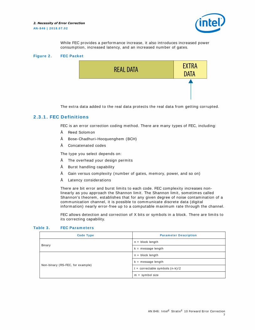
While FEC provides a performance increase, it also introduces increased powerconsumption, increased latency, and an increased number of gates.
Figure 2. FEC Packet
EXTRADATAREAL DATA
The extra data added to the real data protects the real data from getting corrupted.
2.3.1. FEC Definitions
FEC is an error correction coding method. There are many types of FEC, including:
• Reed Solomon
• Bose-Chadhuri-Hocquenghem (BCH)
• Concatenated codes
The type you select depends on:
• The overhead your design permits
• Burst handling capability
• Gain versus complexity (number of gates, memory, power, and so on)
• Latency considerations
There are bit error and burst limits to each code. FEC complexity increases non-linearly as you approach the Shannon limit. The Shannon limit, sometimes calledShannon's theorem, establishes that for any given degree of noise contamination of acommunication channel, it is possible to communicate discrete data (digitalinformation) nearly error-free up to a computable maximum rate through the channel.
FEC allows detection and correction of X bits or symbols in a block. There are limits toits correcting capability.
Table 3. FEC Parameters
Code Type Parameter Description
Binaryn = block length
k = message length
Non-binary (RS-FEC, for example)
n = block length
k = message length
t = correctable symbols (n-k)/2
m = symbol size
2. Necessity of Error Correction
AN-846 | 2018.07.02
AN 846: Intel® Stratix® 10 Forward Error Correction7
3. FEC SelectionEach protocol committee has its own requirement to use certain FEC modes. Theselection depends on the factors discussed in this section.
This section also includes an Ethernet benchmarking example to help you select thebest FEC mode for the 100GbE application in this application note.
3.1. Key Considerations when Choosing a FEC
The primary considerations when choosing a FEC include:
• Hardware complexity
• Coding gain
• Latency
• Power
Coding Gain
Generally, the performance of a transmission line is characterized by the BER, whereBER is the ratio of bits that have errors with respect to the total number of bitsreceived over a transmission line. Additionally, the performance of a data transmissioncode is characterized as a function of the average energy per data bit (Eb) to noisepower spectral density (N0) of the waveform. Eb can be expressed as the signal power(S) times the bit time (Tb). N0 can be expressed as the noise power (N) divided bythe bandwidth. Therefore, Eb/N0 is equal to the SNR (bandwidth/bit rate).
The effectiveness of a FEC code is determined by the reduction in the Eb/N0 needed toensure the specific BER. Coding gain is the reduction in the required Eb/N0 at thesame BER for an uncoded versus a coded system. For example, an uncodedcommunication system operates at a BER of 10−5 at an Eb/N0 of 10 dB. Adding astrong FEC code to this communication system could reduce the ratio of Eb/N0.
Net coding gain (NCG) accounts for the bandwidth expansion needed for the FEC code,and this is associated with increased noise in the receiver side. Coding gain does notaccount for this. This means that the data rate had to increase by a certain percentagein order to transmit both the real data and the extra data (FEC).
AN-846 | 2018.07.02
Intel Corporation. All rights reserved. Intel, the Intel logo, Altera, Arria, Cyclone, Enpirion, MAX, Nios, Quartusand Stratix words and logos are trademarks of Intel Corporation or its subsidiaries in the U.S. and/or othercountries. Intel warrants performance of its FPGA and semiconductor products to current specifications inaccordance with Intel's standard warranty, but reserves the right to make changes to any products and servicesat any time without notice. Intel assumes no responsibility or liability arising out of the application or use of anyinformation, product, or service described herein except as expressly agreed to in writing by Intel. Intelcustomers are advised to obtain the latest version of device specifications before relying on any publishedinformation and before placing orders for products or services.*Other names and brands may be claimed as the property of others.
ISO9001:2008Registered
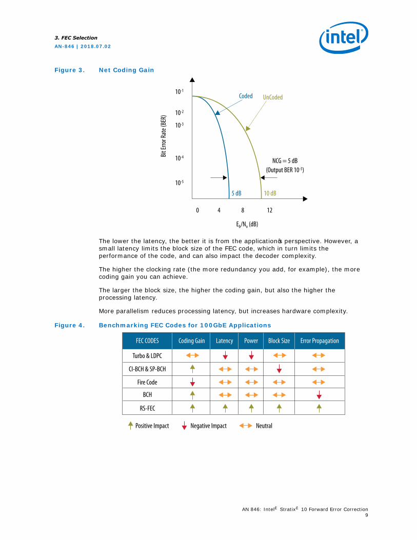
Figure 3. Net Coding Gain
10-1
10-2
10-3
10-4
10-5
0 4 8
5 dB 10 dB
NCG = 5 dB(Output BER 10-5)
Coded UnCoded
Eb/No (dB)
12
Bit E
rror R
ate (
BER)
The lower the latency, the better it is from the application’s perspective. However, asmall latency limits the block size of the FEC code, which in turn limits theperformance of the code, and can also impact the decoder complexity.
The higher the clocking rate (the more redundancy you add, for example), the morecoding gain you can achieve.
The larger the block size, the higher the coding gain, but also the higher theprocessing latency.
More parallelism reduces processing latency, but increases hardware complexity.
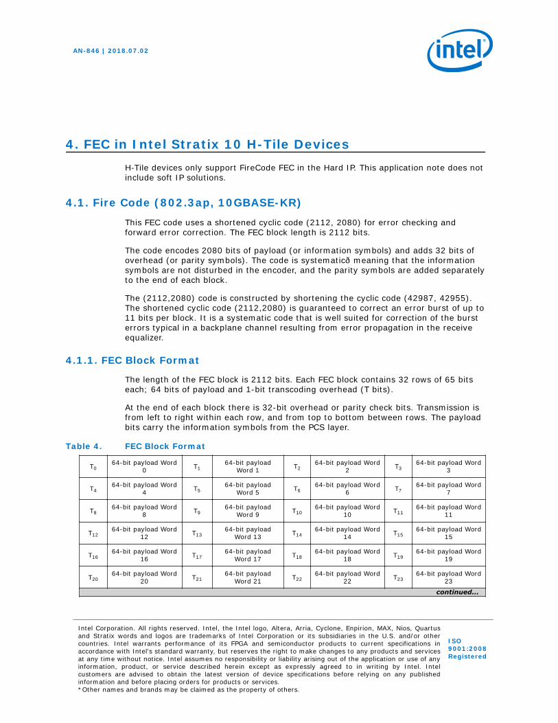
Figure 4. Benchmarking FEC Codes for 100GbE Applications
Turbo & LDPC
FEC CODES
Positive Impact Negative Impact Neutral
Coding Gain Latency Power Block Size Error Propagation
BCH
RS-FEC
Fire Code
CI-BCH & SP-BCH
3. FEC Selection
AN-846 | 2018.07.02
AN 846: Intel® Stratix® 10 Forward Error Correction9
4. FEC in Intel Stratix 10 H-Tile DevicesH-Tile devices only support FireCode FEC in the Hard IP. This application note does notinclude soft IP solutions.
4.1. Fire Code (802.3ap, 10GBASE-KR)
This FEC code uses a shortened cyclic code (2112, 2080) for error checking andforward error correction. The FEC block length is 2112 bits.
The code encodes 2080 bits of payload (or information symbols) and adds 32 bits ofoverhead (or parity symbols). The code is systematic—meaning that the informationsymbols are not disturbed in the encoder, and the parity symbols are added separatelyto the end of each block.
The (2112,2080) code is constructed by shortening the cyclic code (42987, 42955).The shortened cyclic code (2112,2080) is guaranteed to correct an error burst of up to11 bits per block. It is a systematic code that is well suited for correction of the bursterrors typical in a backplane channel resulting from error propagation in the receiveequalizer.
4.1.1. FEC Block Format
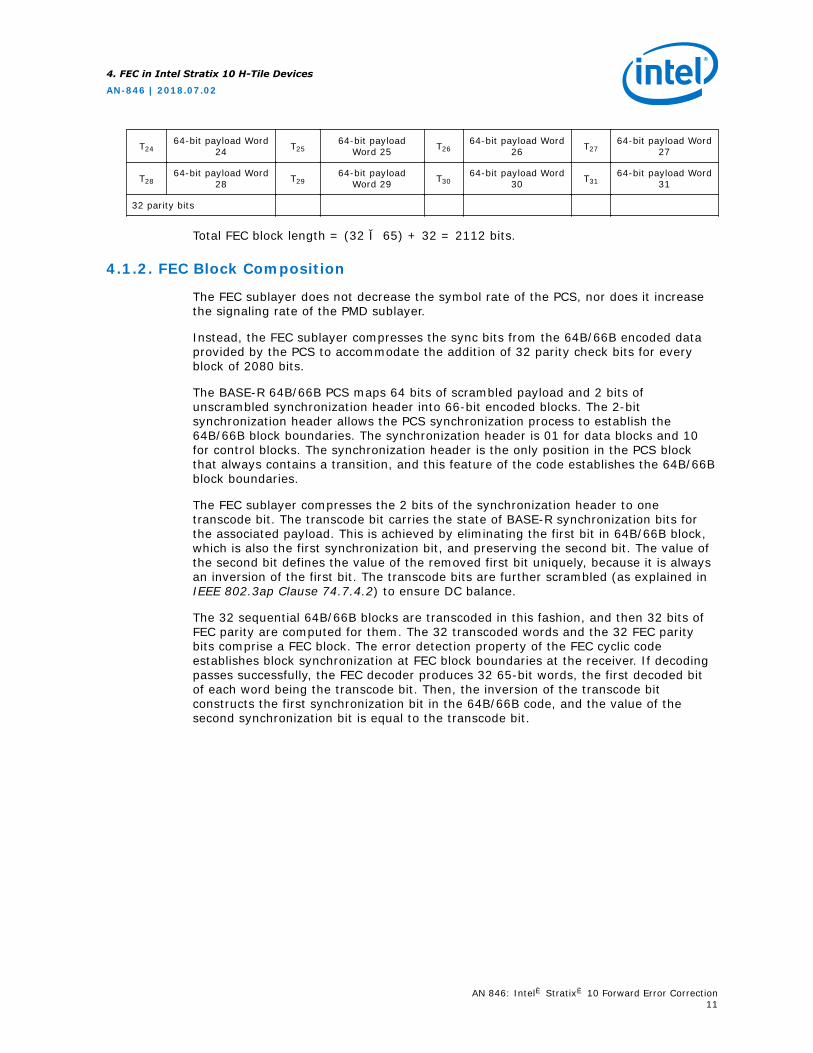
The length of the FEC block is 2112 bits. Each FEC block contains 32 rows of 65 bitseach; 64 bits of payload and 1-bit transcoding overhead (T bits).
At the end of each block there is 32-bit overhead or parity check bits. Transmission isfrom left to right within each row, and from top to bottom between rows. The payloadbits carry the information symbols from the PCS layer.
Table 4. FEC Block Format
T064-bit payload Word
0 T164-bit payload
Word 1 T264-bit payload Word
2 T364-bit payload Word
3
T464-bit payload Word
4 T564-bit payload
Word 5 T664-bit payload Word
6 T764-bit payload Word
7
T864-bit payload Word
8 T964-bit payload
Word 9 T1064-bit payload Word
10 T1164-bit payload Word
11
T1264-bit payload Word
12 T1364-bit payload
Word 13 T1464-bit payload Word
14 T1564-bit payload Word
15
T1664-bit payload Word
16 T1764-bit payload
Word 17 T1864-bit payload Word
18 T1964-bit payload Word
19
T2064-bit payload Word
20 T2164-bit payload
Word 21 T2264-bit payload Word
22 T2364-bit payload Word
23
continued...
AN-846 | 2018.07.02
Intel Corporation. All rights reserved. Intel, the Intel logo, Altera, Arria, Cyclone, Enpirion, MAX, Nios, Quartusand Stratix words and logos are trademarks of Intel Corporation or its subsidiaries in the U.S. and/or othercountries. Intel warrants performance of its FPGA and semiconductor products to current specifications inaccordance with Intel's standard warranty, but reserves the right to make changes to any products and servicesat any time without notice. Intel assumes no responsibility or liability arising out of the application or use of anyinformation, product, or service described herein except as expressly agreed to in writing by Intel. Intelcustomers are advised to obtain the latest version of device specifications before relying on any publishedinformation and before placing orders for products or services.*Other names and brands may be claimed as the property of others.
ISO9001:2008Registered
T2464-bit payload Word
24 T2564-bit payload
Word 25 T2664-bit payload Word
26 T2764-bit payload Word
27
T2864-bit payload Word
28 T2964-bit payload
Word 29 T3064-bit payload Word
30 T3164-bit payload Word
31
32 parity bits
Total FEC block length = (32 × 65) + 32 = 2112 bits.
4.1.2. FEC Block Composition
The FEC sublayer does not decrease the symbol rate of the PCS, nor does it increasethe signaling rate of the PMD sublayer.
Instead, the FEC sublayer compresses the sync bits from the 64B/66B encoded dataprovided by the PCS to accommodate the addition of 32 parity check bits for everyblock of 2080 bits.
The BASE-R 64B/66B PCS maps 64 bits of scrambled payload and 2 bits ofunscrambled synchronization header into 66-bit encoded blocks. The 2-bitsynchronization header allows the PCS synchronization process to establish the64B/66B block boundaries. The synchronization header is 01 for data blocks and 10for control blocks. The synchronization header is the only position in the PCS blockthat always contains a transition, and this feature of the code establishes the 64B/66Bblock boundaries.
The FEC sublayer compresses the 2 bits of the synchronization header to onetranscode bit. The transcode bit carries the state of BASE-R synchronization bits forthe associated payload. This is achieved by eliminating the first bit in 64B/66B block,which is also the first synchronization bit, and preserving the second bit. The value ofthe second bit defines the value of the removed first bit uniquely, because it is alwaysan inversion of the first bit. The transcode bits are further scrambled (as explained inIEEE 802.3ap Clause 74.7.4.2) to ensure DC balance.
The 32 sequential 64B/66B blocks are transcoded in this fashion, and then 32 bits ofFEC parity are computed for them. The 32 transcoded words and the 32 FEC paritybits comprise a FEC block. The error detection property of the FEC cyclic codeestablishes block synchronization at FEC block boundaries at the receiver. If decodingpasses successfully, the FEC decoder produces 32 65-bit words, the first decoded bitof each word being the transcode bit. Then, the inversion of the transcode bitconstructs the first synchronization bit in the 64B/66B code, and the value of thesecond synchronization bit is equal to the transcode bit.
4. FEC in Intel Stratix 10 H-Tile Devices
AN-846 | 2018.07.02
AN 846: Intel® Stratix® 10 Forward Error Correction11
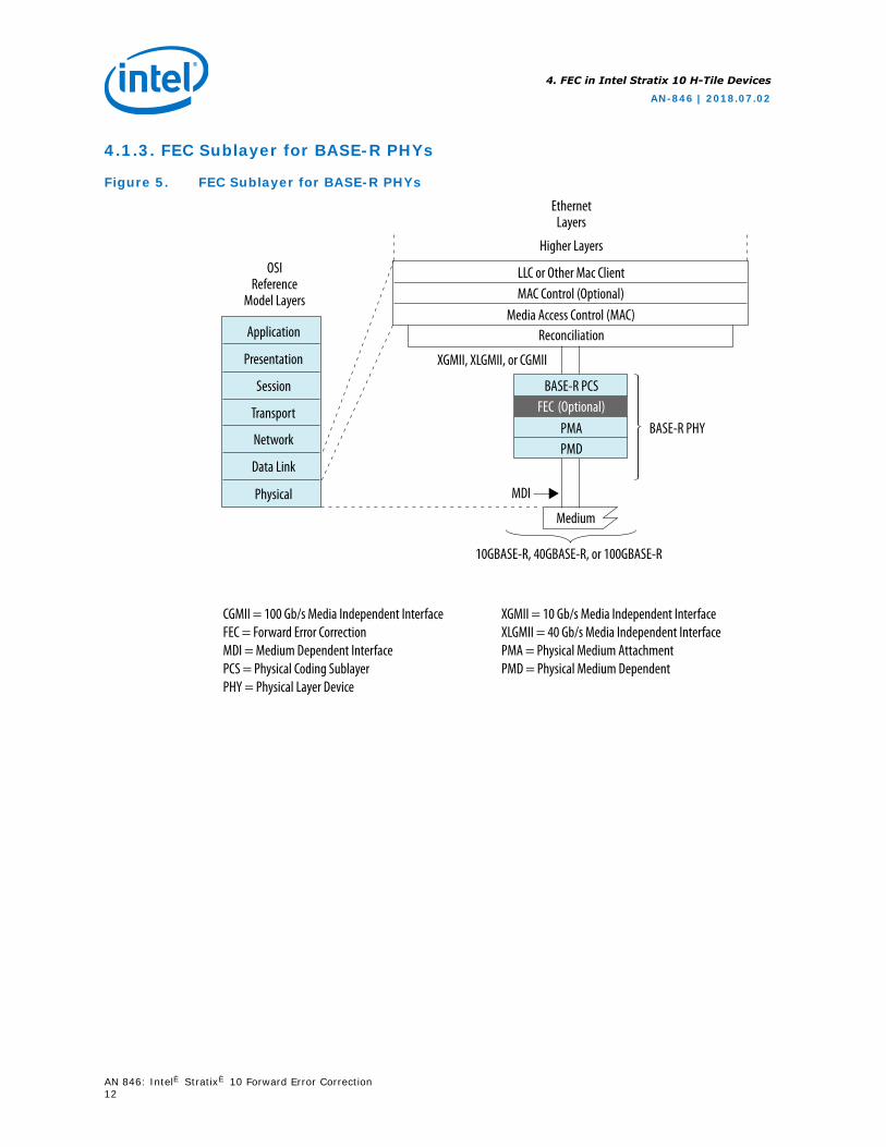
4.1.3. FEC Sublayer for BASE-R PHYs
Figure 5. FEC Sublayer for BASE-R PHYs
CGMII = 100 Gb/s Media Independent InterfaceFEC = Forward Error CorrectionMDI = Medium Dependent InterfacePCS = Physical Coding SublayerPHY = Physical Layer Device
XGMII = 10 Gb/s Media Independent InterfaceXLGMII = 40 Gb/s Media Independent InterfacePMA = Physical Medium AttachmentPMD = Physical Medium Dependent
OSIReference
Model Layers
Application
EthernetLayers
Higher Layers
Reconciliation
FEC (Optional)BASE-R PHY
PMD
MDI
Medium
PMA
BASE-R PCS
MAC Control (Optional)Media Access Control (MAC)
XGMII, XLGMII, or CGMII
LLC or Other Mac Client
Presentation
Session
Transport
Network
Data Link
Physical
10GBASE-R, 40GBASE-R, or 100GBASE-R
4. FEC in Intel Stratix 10 H-Tile Devices
AN-846 | 2018.07.02
AN 846: Intel® Stratix® 10 Forward Error Correction12
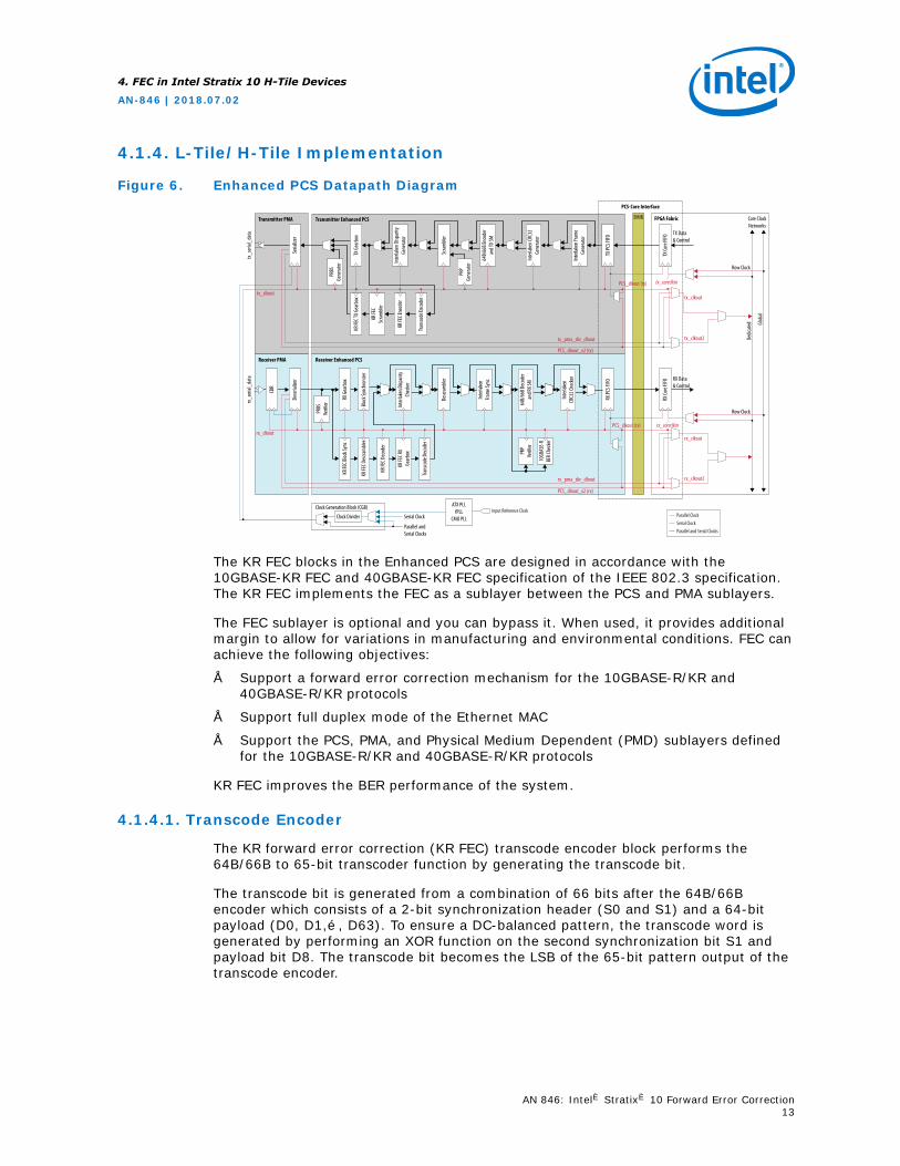
4.1.4. L-Tile/H-Tile Implementation
Figure 6. Enhanced PCS Datapath Diagram
Transmitter PMA Transmitter Enhanced PCS FPGA Fabric
Receiver PMA Receiver Enhanced PCS
EMIB
PCS-Core Interface
64B/
66B E
ncod
eran
d TX S
M
Inte
rlake
n CRC
32Ge
nera
tor
Inte
rlake
n Fra
me
Gene
rato
r
64B/
66B D
ecod
eran
d RX S
M
Inte
rlake
nFra
me S
ync
Inte
rlake
n Disp
arity
Chec
ker
KR FE
CSc
ram
bler
PRP
Gene
rato
r
PRBS
Gene
rato
r
KR FE
C RX
Gear
box
PRBS
Verif
ier
Trans
code
Dec
oder
KR FE
C Bloc
k Syn
c
KR FE
C Des
cram
bler
KR FE
C Dec
oder
10GB
ASE-
RBE
R Che
cker
PRP
Verif
ier
ATX PLLfPLL
CMU PLL
TX G
earb
ox
RX G
earb
ox
Inte
rlake
n Disp
arity
Gene
rato
r
Scra
mble
r
Bloc
k Syn
chro
nizer
Inte
rlake
nCR
C32 C
heck
er
Descr
amble
r
Trans
code
Enco
der
KR FE
C Enc
oder
KR FE
C TX G
earb
ox
RX Data& Control
TX Data& Control
Row Clock
tx_clkout
tx_clkout2
tx_coreclkinPCS_clkout (tx)
PCS_clkout (rx)
Clock Divider Serial Clock
Parallel andSerial Clocks
Clock Generation Block (CGB) Input Reference Clock
Dese
rializ
erSe
rializ
er
TX PC
S FIFO
RX PC
S FIFO
TX Co
re FI
FORX
Core
FIFO
rx_s
erial
_dat
atx
_ser
ial_d
ata
Parallel ClockSerial ClockParallel and Serial Clocks
tx_pma_div_clkout
PCS_clkout_x2 (tx)
tx_clkout
Row Clock
rx_clkout
rx_clkout2
rx_coreclkin
rx_pma_div_clkout
PCS_clkout_x2 (rx)
CDR
Dedic
ated Gl
obal
Core ClockNetworks
rx_clkout
The KR FEC blocks in the Enhanced PCS are designed in accordance with the10GBASE-KR FEC and 40GBASE-KR FEC specification of the IEEE 802.3 specification.The KR FEC implements the FEC as a sublayer between the PCS and PMA sublayers.
The FEC sublayer is optional and you can bypass it. When used, it provides additionalmargin to allow for variations in manufacturing and environmental conditions. FEC canachieve the following objectives:
• Support a forward error correction mechanism for the 10GBASE-R/KR and40GBASE-R/KR protocols
• Support full duplex mode of the Ethernet MAC
• Support the PCS, PMA, and Physical Medium Dependent (PMD) sublayers definedfor the 10GBASE-R/KR and 40GBASE-R/KR protocols
KR FEC improves the BER performance of the system.
4.1.4.1. Transcode Encoder
The KR forward error correction (KR FEC) transcode encoder block performs the64B/66B to 65-bit transcoder function by generating the transcode bit.
The transcode bit is generated from a combination of 66 bits after the 64B/66Bencoder which consists of a 2-bit synchronization header (S0 and S1) and a 64-bitpayload (D0, D1,…, D63). To ensure a DC-balanced pattern, the transcode word isgenerated by performing an XOR function on the second synchronization bit S1 andpayload bit D8. The transcode bit becomes the LSB of the 65-bit pattern output of thetranscode encoder.
4. FEC in Intel Stratix 10 H-Tile Devices
AN-846 | 2018.07.02
AN 846: Intel® Stratix® 10 Forward Error Correction13
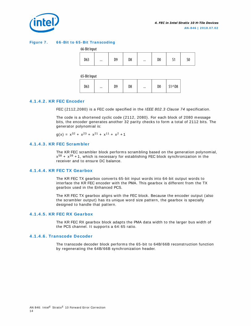
Figure 7. 66-Bit to 65-Bit Transcoding
66-Bit Input
D63 ... D9 D8 ... D0 S1 S0
65-Bit Input
D63 ... D9 D8 ... D0 S1^D8
4.1.4.2. KR FEC Encoder
FEC (2112,2080) is a FEC code specified in the IEEE 802.3 Clause 74 specification.
The code is a shortened cyclic code (2112, 2080). For each block of 2080 messagebits, the encoder generates another 32 parity checks to form a total of 2112 bits. Thegenerator polynomial is:
g(x) = x32 + x23 + x21 + x11 + x2 +1
4.1.4.3. KR FEC Scrambler
The KR FEC scrambler block performs scrambling based on the generation polynomial,x58 + x39 +1, which is necessary for establishing FEC block synchronization in thereceiver and to ensure DC balance.
4.1.4.4. KR FEC TX Gearbox
The KR FEC TX gearbox converts 65-bit input words into 64-bit output words tointerface the KR FEC encoder with the PMA. This gearbox is different from the TXgearbox used in the Enhanced PCS.
The KR FEC TX gearbox aligns with the FEC block. Because the encoder output (alsothe scrambler output) has its unique word size pattern, the gearbox is speciallydesigned to handle that pattern.
4.1.4.5. KR FEC RX Gearbox
The KR FEC RX gearbox block adapts the PMA data width to the larger bus width ofthe PCS channel. It supports a 64:65 ratio.
4.1.4.6. Transcode Decoder
The transcode decoder block performs the 65-bit to 64B/66B reconstruction functionby regenerating the 64B/66B synchronization header.
4. FEC in Intel Stratix 10 H-Tile Devices
AN-846 | 2018.07.02
AN 846: Intel® Stratix® 10 Forward Error Correction14
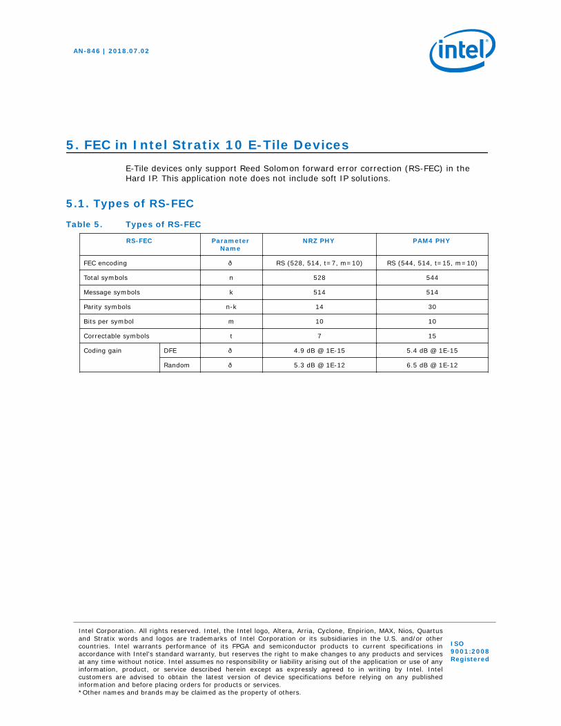
5. FEC in Intel Stratix 10 E-Tile DevicesE-Tile devices only support Reed Solomon forward error correction (RS-FEC) in theHard IP. This application note does not include soft IP solutions.
5.1. Types of RS-FEC
Table 5. Types of RS-FEC
RS-FEC ParameterName
NRZ PHY PAM4 PHY
FEC encoding — RS (528, 514, t=7, m=10) RS (544, 514, t=15, m=10)
Total symbols n 528 544
Message symbols k 514 514
Parity symbols n-k 14 30
Bits per symbol m 10 10
Correctable symbols t 7 15
Coding gain DFE — 4.9 dB @ 1E-15 5.4 dB @ 1E-15
Random — 5.3 dB @ 1E-12 6.5 dB @ 1E-12
AN-846 | 2018.07.02
Intel Corporation. All rights reserved. Intel, the Intel logo, Altera, Arria, Cyclone, Enpirion, MAX, Nios, Quartusand Stratix words and logos are trademarks of Intel Corporation or its subsidiaries in the U.S. and/or othercountries. Intel warrants performance of its FPGA and semiconductor products to current specifications inaccordance with Intel's standard warranty, but reserves the right to make changes to any products and servicesat any time without notice. Intel assumes no responsibility or liability arising out of the application or use of anyinformation, product, or service described herein except as expressly agreed to in writing by Intel. Intelcustomers are advised to obtain the latest version of device specifications before relying on any publishedinformation and before placing orders for products or services.*Other names and brands may be claimed as the property of others.
ISO9001:2008Registered
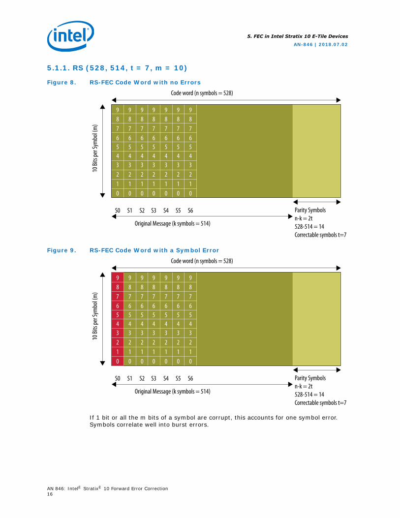
5.1.1. RS (528, 514, t = 7, m = 10)
Figure 8. RS-FEC Code Word with no Errors
Code word (n symbols = 528)10
Bits
per S
ymbo
l (m
)
9 9 9 9 9 9 98 8 8 8 8 8 87 7 7 7 7 7 76 6 6 6 6 6 65 5 5 5 5 5 54 4 4 4 4 4 43 3 3 3 3 3 32 2 2 2 2 2 21 1 1 1 1 1 10 0 0 0 0 0 0
S0 S1 S2 S3 S4 S5 S6
Original Message (k symbols = 514)
Parity Symbolsn-k = 2t528-514 = 14Correctable symbols t=7
Figure 9. RS-FEC Code Word with a Symbol Error
Code word (n symbols = 528)
10 Bi
ts pe
r Sym
bol (
m)
9 9 9 9 9 9 98 8 8 8 8 8 87 7 7 7 7 7 76 6 6 6 6 6 65 5 5 5 5 5 54 4 4 4 4 4 43 3 3 3 3 3 32 2 2 2 2 2 21 1 1 1 1 1 10 0 0 0 0 0 0
S0 S1 S2 S3 S4 S5 S6
Original Message (k symbols = 514)
Parity Symbolsn-k = 2t528-514 = 14Correctable symbols t=7
If 1 bit or all the m bits of a symbol are corrupt, this accounts for one symbol error.Symbols correlate well into burst errors.
5. FEC in Intel Stratix 10 E-Tile Devices
AN-846 | 2018.07.02
AN 846: Intel® Stratix® 10 Forward Error Correction16
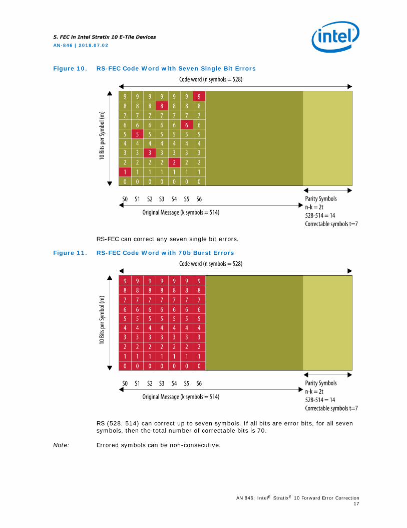
Figure 10. RS-FEC Code Word with Seven Single Bit Errors
Code word (n symbols = 528)
10 Bi
ts pe
r Sym
bol (
m)
9 9 9 9 9 9 98 8 8 8 8 8 87 7 7 7 7 7 76 6 6 6 6 6 65 5 5 5 5 5 54 4 4 4 4 4 43 3 3 3 3 3 32 2 2 2 2 2 21 1 1 1 1 1 10 0 0 0 0 0 0
S0 S1 S2 S3 S4 S5 S6
Original Message (k symbols = 514)
Parity Symbolsn-k = 2t528-514 = 14Correctable symbols t=7
RS-FEC can correct any seven single bit errors.
Figure 11. RS-FEC Code Word with 70b Burst Errors
Code word (n symbols = 528)
10 Bi
ts pe
r Sym
bol (
m)
9 9 9 9 9 9 98 8 8 8 8 8 87 7 7 7 7 7 76 6 6 6 6 6 65 5 5 5 5 5 54 4 4 4 4 4 43 3 3 3 3 3 32 2 2 2 2 2 21 1 1 1 1 1 10 0 0 0 0 0 0
S0 S1 S2 S3 S4 S5 S6
Original Message (k symbols = 514)
Parity Symbolsn-k = 2t528-514 = 14Correctable symbols t=7
RS (528, 514) can correct up to seven symbols. If all bits are error bits, for all sevensymbols, then the total number of correctable bits is 70.
Note: Errored symbols can be non-consecutive.
5. FEC in Intel Stratix 10 E-Tile Devices
AN-846 | 2018.07.02
AN 846: Intel® Stratix® 10 Forward Error Correction17
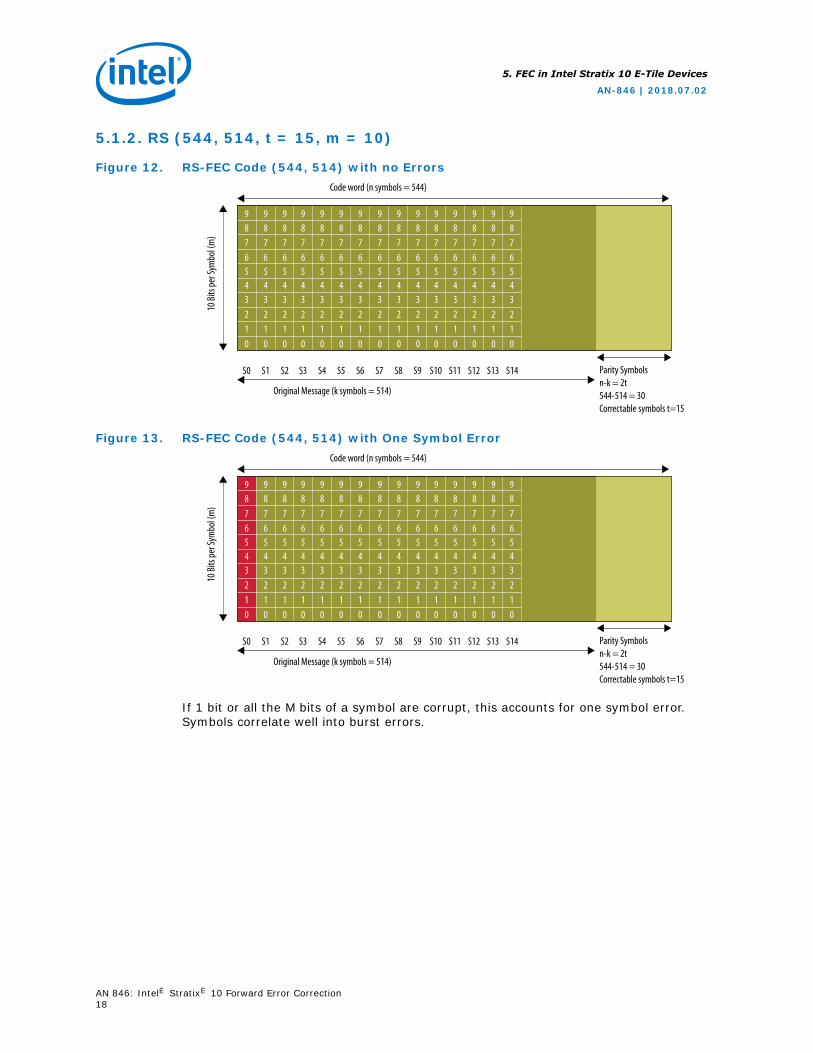
5.1.2. RS (544, 514, t = 15, m = 10)
Figure 12. RS-FEC Code (544, 514) with no ErrorsCode word (n symbols = 544)
10 Bi
ts pe
r Sym
bol (
m)
9 9 9 9 9 9 98 8 8 8 8 8 87 7 7 7 7 7 76 6 6 6 6 6 65 5 5 5 5 5 54 4 4 4 4 4 43 3 3 3 3 3 32 2 2 2 2 2 21 1 1 1 1 1 10 0 0 0 0 0 0
S0 S1 S2 S3 S4 S5 S6
Original Message (k symbols = 514)
Parity Symbolsn-k = 2t544-514 = 30Correctable symbols t=15
9 9 9 9 9 9 98 8 8 8 8 8 87 7 7 7 7 7 76 6 6 6 6 6 65 5 5 5 5 5 54 4 4 4 4 4 43 3 3 3 3 3 32 2 2 2 2 2 21 1 1 1 1 1 10 0 0 0 0 0 0
9876543210
S7 S8 S9 S10 S11 S12 S13 S14
Figure 13. RS-FEC Code (544, 514) with One Symbol ErrorCode word (n symbols = 544)
10 Bi
ts pe
r Sym
bol (
m)
9 9 9 9 9 9 98 8 8 8 8 8 87 7 7 7 7 7 76 6 6 6 6 6 65 5 5 5 5 5 54 4 4 4 4 4 43 3 3 3 3 3 32 2 2 2 2 2 21 1 1 1 1 1 10 0 0 0 0 0 0
S0 S1 S2 S3 S4 S5 S6
Original Message (k symbols = 514)
Parity Symbolsn-k = 2t544-514 = 30Correctable symbols t=15
9 9 9 9 9 9 98 8 8 8 8 8 87 7 7 7 7 7 76 6 6 6 6 6 65 5 5 5 5 5 54 4 4 4 4 4 43 3 3 3 3 3 32 2 2 2 2 2 21 1 1 1 1 1 10 0 0 0 0 0 0
9876543210
S7 S8 S9 S10 S11 S12 S13 S14
If 1 bit or all the M bits of a symbol are corrupt, this accounts for one symbol error.Symbols correlate well into burst errors.
5. FEC in Intel Stratix 10 E-Tile Devices
AN-846 | 2018.07.02
AN 846: Intel® Stratix® 10 Forward Error Correction18
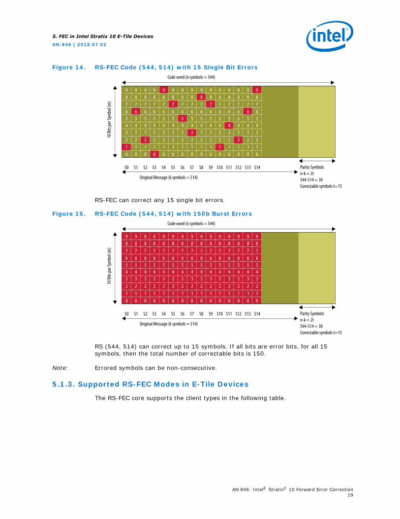
Figure 14. RS-FEC Code (544, 514) with 15 Single Bit ErrorsCode word (n symbols = 544)
10 Bi
ts pe
r Sym
bol (
m)
9 9 9 9 9 9 98 8 8 8 8 8 87 7 7 7 7 7 76 6 6 6 6 6 65 5 5 5 5 5 54 4 4 4 4 4 43 3 3 3 3 3 32 2 2 2 2 2 21 1 1 1 1 1 10 0 0 0 0 0 0
S0 S1 S2 S3 S4 S5 S6
Original Message (k symbols = 514)
Parity Symbolsn-k = 2t544-514 = 30Correctable symbols t=15
9 9 9 9 9 9 98 8 8 8 8 8 87 7 7 7 7 7 76 6 6 6 6 6 65 5 5 5 5 5 54 4 4 4 4 4 43 3 3 3 3 3 32 2 2 2 2 2 21 1 1 1 1 1 10 0 0 0 0 0 0
9876543210
S7 S8 S9 S10 S11 S12 S13 S14
RS-FEC can correct any 15 single bit errors.
Figure 15. RS-FEC Code (544, 514) with 150b Burst ErrorsCode word (n symbols = 544)
10 Bi
ts pe
r Sym
bol (
m)
9 9 9 9 9 9 98 8 8 8 8 8 87 7 7 7 7 7 76 6 6 6 6 6 65 5 5 5 5 5 54 4 4 4 4 4 43 3 3 3 3 3 32 2 2 2 2 2 21 1 1 1 1 1 10 0 0 0 0 0 0
S0 S1 S2 S3 S4 S5 S6
Original Message (k symbols = 514)
Parity Symbolsn-k = 2t544-514 = 30Correctable symbols t=15
9 9 9 9 9 9 98 8 8 8 8 8 87 7 7 7 7 7 76 6 6 6 6 6 65 5 5 5 5 5 54 4 4 4 4 4 43 3 3 3 3 3 32 2 2 2 2 2 21 1 1 1 1 1 10 0 0 0 0 0 0
9876543210
S7 S8 S9 S10 S11 S12 S13 S14
RS (544, 514) can correct up to 15 symbols. If all bits are error bits, for all 15symbols, then the total number of correctable bits is 150.
Note: Errored symbols can be non-consecutive.
5.1.3. Supported RS-FEC Modes in E-Tile Devices
The RS-FEC core supports the client types in the following table.
5. FEC in Intel Stratix 10 E-Tile Devices
AN-846 | 2018.07.02
AN 846: Intel® Stratix® 10 Forward Error Correction19
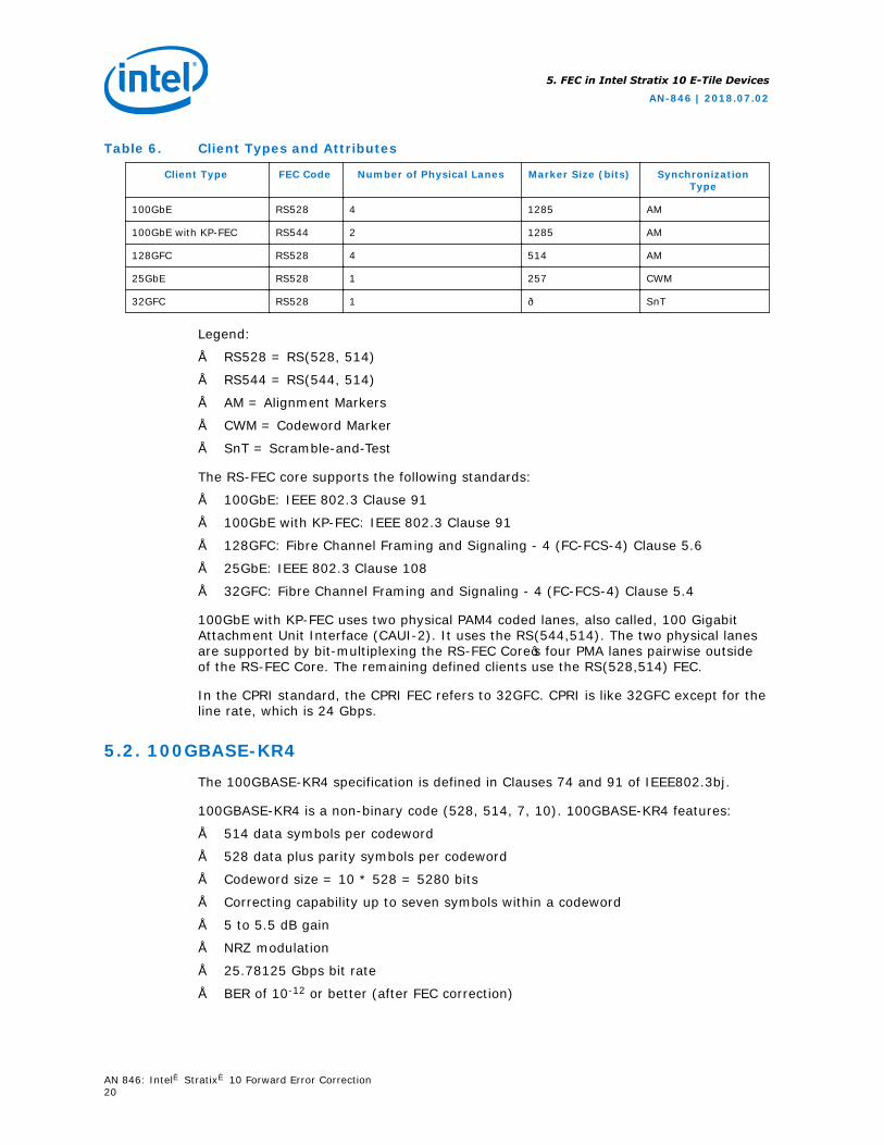
Table 6. Client Types and Attributes
Client Type FEC Code Number of Physical Lanes Marker Size (bits) SynchronizationType
100GbE RS528 4 1285 AM
100GbE with KP-FEC RS544 2 1285 AM
128GFC RS528 4 514 AM
25GbE RS528 1 257 CWM
32GFC RS528 1 — SnT
Legend:
• RS528 = RS(528, 514)
• RS544 = RS(544, 514)
• AM = Alignment Markers
• CWM = Codeword Marker
• SnT = Scramble-and-Test
The RS-FEC core supports the following standards:
• 100GbE: IEEE 802.3 Clause 91
• 100GbE with KP-FEC: IEEE 802.3 Clause 91
• 128GFC: Fibre Channel Framing and Signaling - 4 (FC-FCS-4) Clause 5.6
• 25GbE: IEEE 802.3 Clause 108
• 32GFC: Fibre Channel Framing and Signaling - 4 (FC-FCS-4) Clause 5.4
100GbE with KP-FEC uses two physical PAM4 coded lanes, also called, 100 GigabitAttachment Unit Interface (CAUI-2). It uses the RS(544,514). The two physical lanesare supported by bit-multiplexing the RS-FEC Core’s four PMA lanes pairwise outsideof the RS-FEC Core. The remaining defined clients use the RS(528,514) FEC.
In the CPRI standard, the CPRI FEC refers to 32GFC. CPRI is like 32GFC except for theline rate, which is 24 Gbps.
5.2. 100GBASE-KR4
The 100GBASE-KR4 specification is defined in Clauses 74 and 91 of IEEE802.3bj.
100GBASE-KR4 is a non-binary code (528, 514, 7, 10). 100GBASE-KR4 features:
• 514 data symbols per codeword
• 528 data plus parity symbols per codeword
• Codeword size = 10 * 528 = 5280 bits
• Correcting capability up to seven symbols within a codeword
• 5 to 5.5 dB gain
• NRZ modulation
• 25.78125 Gbps bit rate
• BER of 10-12 or better (after FEC correction)
5. FEC in Intel Stratix 10 E-Tile Devices
AN-846 | 2018.07.02
AN 846: Intel® Stratix® 10 Forward Error Correction20
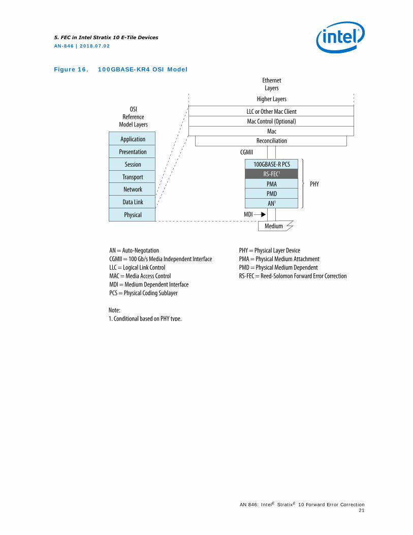
Figure 16. 100GBASE-KR4 OSI Model
AN = Auto-NegotationCGMII = 100 Gb/s Media Independent InterfaceLLC = Logical Link ControlMAC = Media Access ControlMDI = Medium Dependent InterfacePCS = Physical Coding Sublayer
PHY = Physical Layer DevicePMA = Physical Medium AttachmentPMD = Physical Medium DependentRS-FEC = Reed-Solomon Forward Error Correction
OSIReference
Model Layers
Application
EthernetLayers
Higher Layers
Reconciliation
RS-FEC1
AN1
PHYPMD
MDI
Medium
PMA
100GBASE-R PCS
Mac Control (Optional)Mac
CGMII
LLC or Other Mac Client
Presentation
Session
Transport
Network
Data Link
Physical
Note:1. Conditional based on PHY type.
5. FEC in Intel Stratix 10 E-Tile Devices
AN-846 | 2018.07.02
AN 846: Intel® Stratix® 10 Forward Error Correction21
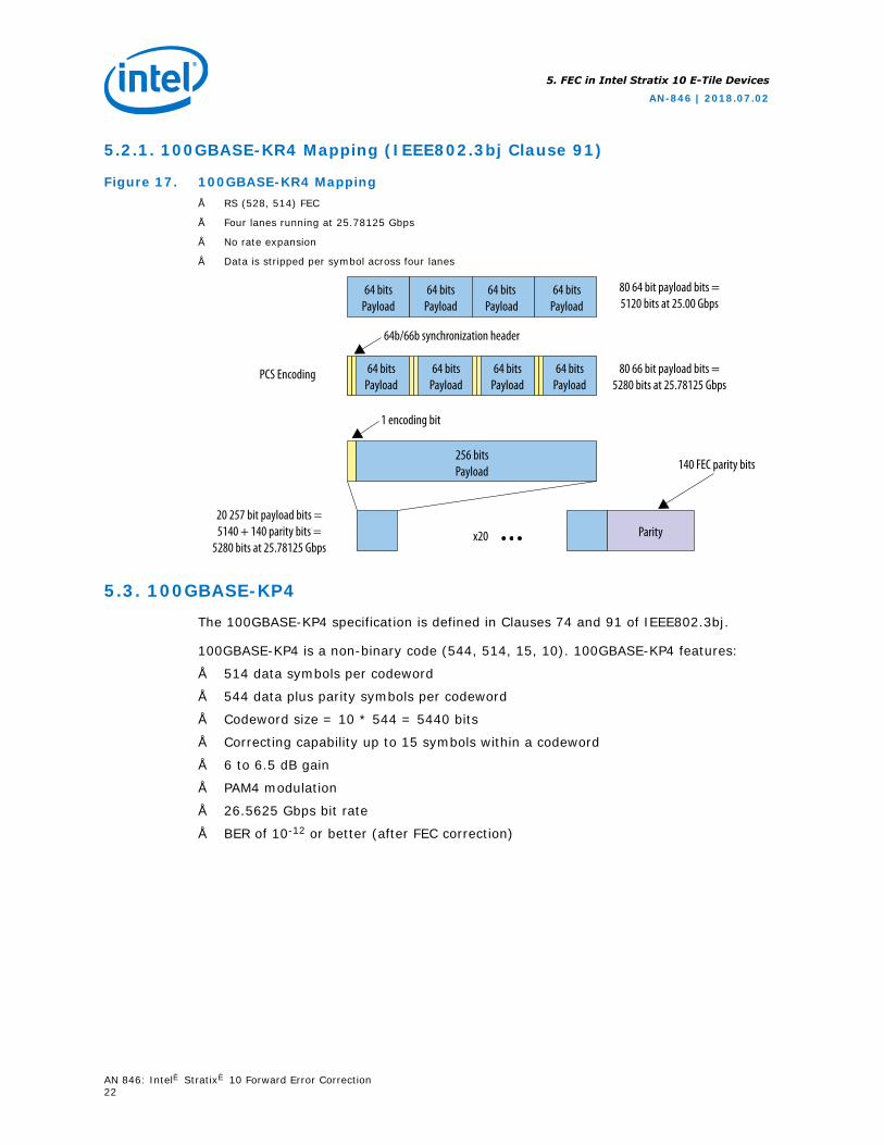
5.2.1. 100GBASE-KR4 Mapping (IEEE802.3bj Clause 91)
Figure 17. 100GBASE-KR4 Mapping• RS (528, 514) FEC
• Four lanes running at 25.78125 Gbps
• No rate expansion
• Data is stripped per symbol across four lanes
64 bitsPayload
64 bitsPayload
64 bitsPayload
64 bitsPayload
64 bitsPayload
64 bitsPayload
64 bitsPayload
64 bitsPayload
64b/66b synchronization header
80 64 bit payload bits =5120 bits at 25.00 Gbps
80 66 bit payload bits =5280 bits at 25.78125 Gbps
140 FEC parity bits256 bitsPayload
1 encoding bit
Parityx20
20 257 bit payload bits =5140 + 140 parity bits =
5280 bits at 25.78125 Gbps
PCS Encoding
5.3. 100GBASE-KP4
The 100GBASE-KP4 specification is defined in Clauses 74 and 91 of IEEE802.3bj.
100GBASE-KP4 is a non-binary code (544, 514, 15, 10). 100GBASE-KP4 features:
• 514 data symbols per codeword
• 544 data plus parity symbols per codeword
• Codeword size = 10 * 544 = 5440 bits
• Correcting capability up to 15 symbols within a codeword
• 6 to 6.5 dB gain
• PAM4 modulation
• 26.5625 Gbps bit rate
• BER of 10-12 or better (after FEC correction)
5. FEC in Intel Stratix 10 E-Tile Devices
AN-846 | 2018.07.02
AN 846: Intel® Stratix® 10 Forward Error Correction22
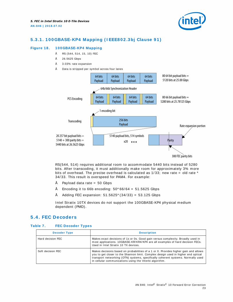
5.3.1. 100GBASE-KP4 Mapping (IEEE802.3bj Clause 91)
Figure 18. 100GBASE-KP4 Mapping• RS (544, 514, 15, 10) FEC
• 26.5625 Gbps
• 3.03% rate expansion
• Data is stripped per symbol across four lanes
64 bitsPayload
64 bitsPayload
64 bitsPayload
64 bitsPayload
64 bitsPayload
64 bitsPayload
64 bitsPayload
64 bitsPayload
64b/66b Synchronization Header
80 64 bit payload bits =5120 bits at 25.00 Gbps
80 66 bit payload bits =5280 bits at 25.78125 Gbps
300 FEC parity bits
256 bitsPayload
1 encoding bit
Parityx20
20 257 bit payload bits =5140 + 300 parity bits =
5440 bits at 26.5625 Gbps
PCS Encoding
Transcoding
5140 payload bits, 514 symbols
Rate expansion portion
RS(544, 514) requires additional room to accommodate 5440 bits instead of 5280bits. After transcoding, it must additionally make room for approximately 3% morebits of overhead. The precise overhead is calculated as 1/33; new rate = old rate *34/33. This result is overspeed for PAM4. For example:
• Payload data rate = 50 Gbps
• Encoding it to 66b encoding: 50*66/64 = 51.5625 Gbps
• Adding FEC expansion: 51.5625*(34/33) = 53.125 Gbps
Intel Stratix 10TX devices do not support the 100GBASE-KP4 physical mediumdependent (PMD).
5.4. FEC Decoders
Table 7. FEC Decoder Types
Decoder Type Description
Hard decision FEC Makes exact decisions of 1s or 0s. Good gain versus complexity. Broadly used inmost applications. 10GBASE-KR/KR4/KP4 are all examples of hard decision FECs.Used in Intel Stratix 10 TX devices.
Soft decision FEC Makes decisions based on probabilities of a 1 or 0. Provides higher gain and allowsyou to get closer to the Shannon limit. Complex design used in higher end opticaltransport networking (OTN) systems, specifically coherent systems. Normally usedin cellular communications using the Viterbi algorithm.
5. FEC in Intel Stratix 10 E-Tile Devices
AN-846 | 2018.07.02
AN 846: Intel® Stratix® 10 Forward Error Correction23
5.5. Specifications
The IEEE802.3ap specification defines an insertion loss and return loss of 25 dB at5.15625 GHz. The 1e-12 BER requirement is a system specification that is met with orwithout FEC.
The IEEE802.3bj specification specifies 100GBASE-KR4 for 100 Gbps operation usingNRZ over four differential pairs where the insertion loss does not exceed 35 dB at 12.9GHz. 100GBASE-KR4 uses:
• The PCS defined in Clause 82
• The RS-FEC defined in Clause 91
• The PMA defined in Clause 83
• The PMD defined in Clause 93
IEEE802.3bj also specifies 100GBASE-KP4 for 100 Gbps operation using PAM4 overtwo differential pairs where the insertion loss does not exceed 33 dB at 7 GHz.100GBASE-KP4 uses:
• The PCS defined in Clause 82
• The RS-FEC defined in Clause 91
• The PMA and PMD defined in Clause 94
The CEI 56G long reach (LR) specification discusses multiple FECs, but the standard isKP4 FEC with PAM4. The 1e-15 BER requirement is a system specification met withFEC.
5. FEC in Intel Stratix 10 E-Tile Devices
AN-846 | 2018.07.02
AN 846: Intel® Stratix® 10 Forward Error Correction24
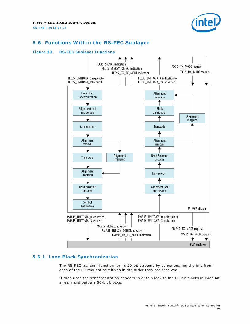
5.6. Functions Within the RS-FEC Sublayer
Figure 19. RS-FEC Sublayer Functions
Lane block synchronization
FEC:IS_UNITDATA_0.request to FEC:IS_UNITDATA_19.request
FEC:IS_UNITDATA_0.indication to FEC:IS_UNITDATA_19.indication
FEC:IS_TX_MODE.request
Alignment lock and deskew
Alignment removal
Alignment mapping
Alignment mapping
Alignment insertion
Alignment insertion
Alignment removal
Reed-Solomondecoder
Alignment lock and deskew
Block distribution
Transcode
Lane reorder
RS-FEC Sublayer
PMA Sublayer
Reed-Solomonencoder
Symboldistribution
Lane reorder
Transcode
FEC:IS_RX_MODE.request
FEC:IS_SIGNAL.indicationFEC:IS_ENERGY_DETECT.indication
FEC:IS_RX_TX_MODE.indication
PMA:IS_UNITDATA_0.request toPMA:IS_UNITDATA_3.request
PMA:IS_UNITDATA_0.indication toPMA:IS_UNITDATA_3.indication
PMA:IS_TX_MODE.requestPMA:IS_RX_MODE.request
PMA:IS_SIGNAL.indicationPMA:IS_ENERGY_DETECT.indication
PMA:IS_RX_TX_MODE.indication
5.6.1. Lane Block Synchronization
The RS-FEC transmit function forms 20-bit streams by concatenating the bits fromeach of the 20 request primitives in the order they are received.
It then uses the synchronization headers to obtain lock to the 66-bit blocks in each bitstream and outputs 66-bit blocks.
5. FEC in Intel Stratix 10 E-Tile Devices
AN-846 | 2018.07.02
AN 846: Intel® Stratix® 10 Forward Error Correction25
5.6.2. Alignment Lock and Deskew
Once the RS-FEC transmit function achieves block lock on a PCS lane, it beginsobtaining alignment marker lock.
Alignment marker lock identifies the PCS lane number received on a particular lane ofthe service interface. After alignment marker lock is achieved on all 20 lanes, all inter-lane skew is removed. The RS-FEC transmit function supports a maximum skew of 49ns between PCS lanes, and a maximum skew variation of 400 ps.
5.6.3. Lane Re-order
PCS lanes can be received on different lanes of the service interface from which theywere originally transmitted due to skew between lanes and multiplexing by the PMA.
The RS-FEC transmit function orders the PCS lanes according to the PCS lane number.
5.6.4. Alignment Marker Removal
After all PCS lanes are aligned and deskewed, the PCS lanes are multiplexed togetherin the proper order to reconstruct the original stream of blocks. At this point, thealignment markers are removed from the data stream.
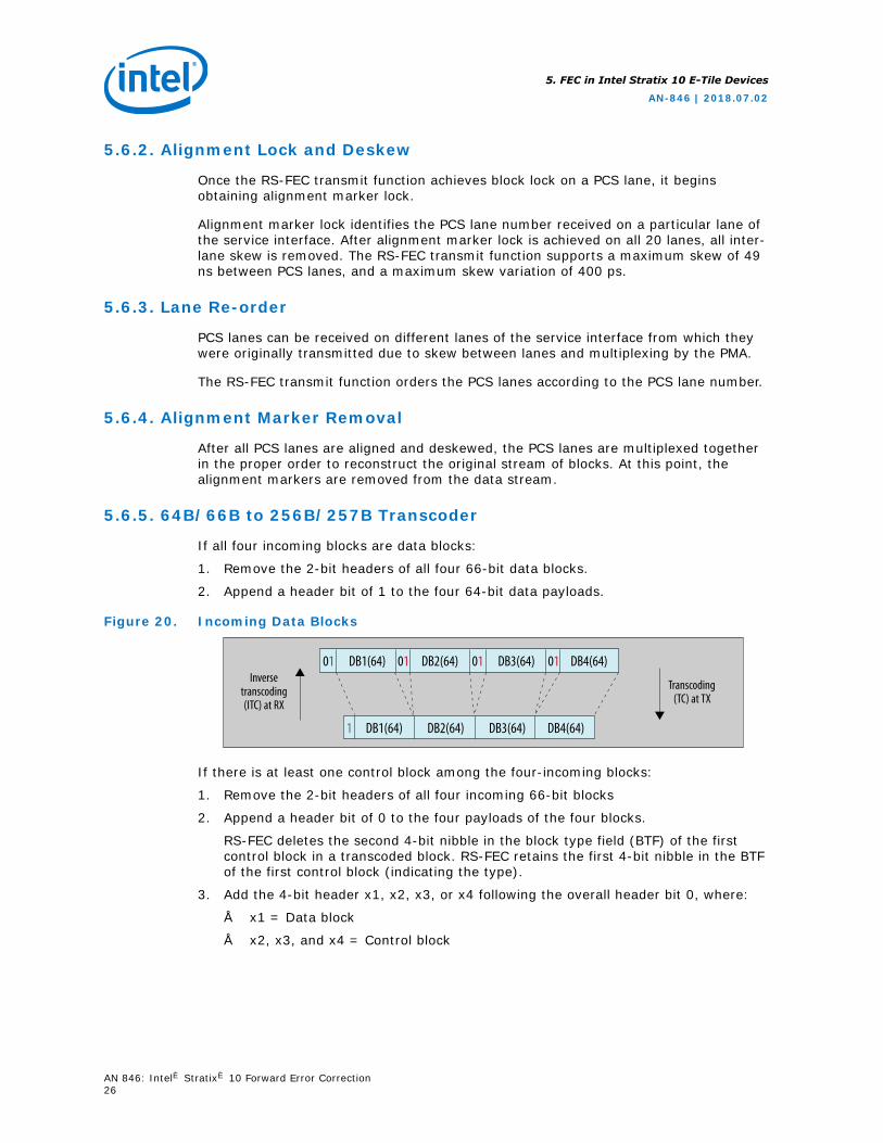
5.6.5. 64B/66B to 256B/257B Transcoder
If all four incoming blocks are data blocks:
1. Remove the 2-bit headers of all four 66-bit data blocks.
2. Append a header bit of 1 to the four 64-bit data payloads.
Figure 20. Incoming Data Blocks
Inversetranscoding(ITC) at RX
Transcoding(TC) at TX
01 01 01 01DB1(64) DB2(64) DB3(64) DB4(64)
1 DB1(64) DB2(64) DB3(64) DB4(64)
If there is at least one control block among the four-incoming blocks:
1. Remove the 2-bit headers of all four incoming 66-bit blocks
2. Append a header bit of 0 to the four payloads of the four blocks.
RS-FEC deletes the second 4-bit nibble in the block type field (BTF) of the firstcontrol block in a transcoded block. RS-FEC retains the first 4-bit nibble in the BTFof the first control block (indicating the type).
3. Add the 4-bit header x1, x2, x3, or x4 following the overall header bit 0, where:
• x1 = Data block
• x2, x3, and x4 = Control block
5. FEC in Intel Stratix 10 E-Tile Devices
AN-846 | 2018.07.02
AN 846: Intel® Stratix® 10 Forward Error Correction26
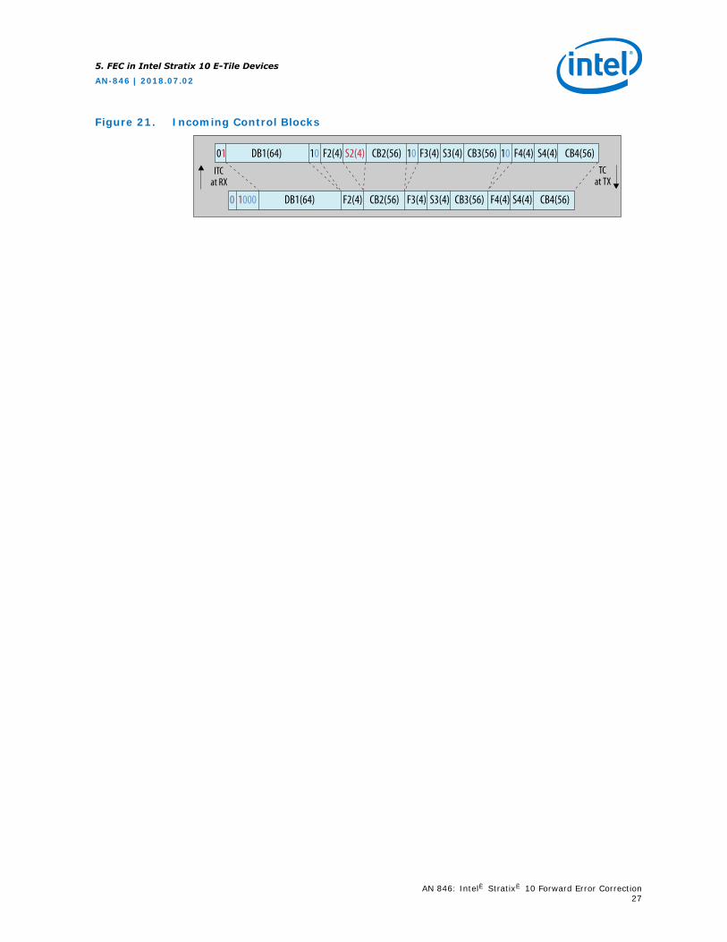
Figure 21. Incoming Control Blocks
ITCat RX
01 10 10 10DB1(64) F2(4) F3(4) F4(4)S2(4) S3(4) S4(4)CB2(56) CB3(56) CB4(56)
0 1000 DB1(64) F3(4) F4(4)F2(4) S3(4) S4(4)CB2(56) CB3(56) CB4(56)
TCat TX
5. FEC in Intel Stratix 10 E-Tile Devices
AN-846 | 2018.07.02
AN 846: Intel® Stratix® 10 Forward Error Correction27
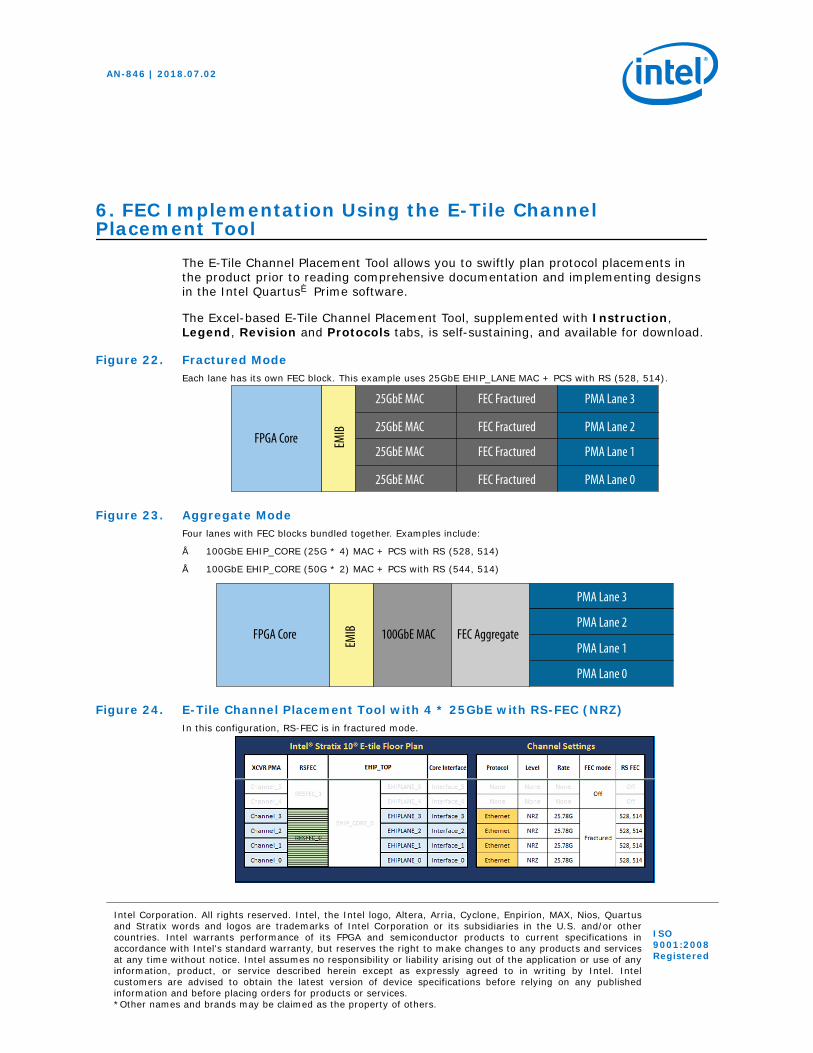
6. FEC Implementation Using the E-Tile ChannelPlacement Tool
The E-Tile Channel Placement Tool allows you to swiftly plan protocol placements inthe product prior to reading comprehensive documentation and implementing designsin the Intel Quartus® Prime software.
The Excel-based E-Tile Channel Placement Tool, supplemented with Instruction,Legend, Revision and Protocols tabs, is self-sustaining, and available for download.
Figure 22. Fractured ModeEach lane has its own FEC block. This example uses 25GbE EHIP_LANE MAC + PCS with RS (528, 514).
25GbE MAC FEC Fractured PMA Lane 3
25GbE MAC FEC Fractured PMA Lane 2
25GbE MAC FEC Fractured PMA Lane 1
25GbE MAC FEC Fractured PMA Lane 0
FPGA Core EMIB
Figure 23. Aggregate ModeFour lanes with FEC blocks bundled together. Examples include:
• 100GbE EHIP_CORE (25G * 4) MAC + PCS with RS (528, 514)
• 100GbE EHIP_CORE (50G * 2) MAC + PCS with RS (544, 514)
PMA Lane 3
PMA Lane 2
PMA Lane 1
PMA Lane 0
FPGA Core 100GbE MAC FEC Aggregate
EMIB
Figure 24. E-Tile Channel Placement Tool with 4 * 25GbE with RS-FEC (NRZ)In this configuration, RS-FEC is in fractured mode.
AN-846 | 2018.07.02
Intel Corporation. All rights reserved. Intel, the Intel logo, Altera, Arria, Cyclone, Enpirion, MAX, Nios, Quartusand Stratix words and logos are trademarks of Intel Corporation or its subsidiaries in the U.S. and/or othercountries. Intel warrants performance of its FPGA and semiconductor products to current specifications inaccordance with Intel's standard warranty, but reserves the right to make changes to any products and servicesat any time without notice. Intel assumes no responsibility or liability arising out of the application or use of anyinformation, product, or service described herein except as expressly agreed to in writing by Intel. Intelcustomers are advised to obtain the latest version of device specifications before relying on any publishedinformation and before placing orders for products or services.*Other names and brands may be claimed as the property of others.
ISO9001:2008Registered
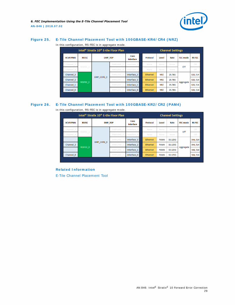
Figure 25. E-Tile Channel Placement Tool with 100GBASE-KR4/CR4 (NRZ)In this configuration, RS-FEC is in aggregate mode.
Figure 26. E-Tile Channel Placement Tool with 100GBASE-KR2/CR2 (PAM4)In this configuration, RS-FEC is in aggregate mode.
Related Information
E-Tile Channel Placement Tool
6. FEC Implementation Using the E-Tile Channel Placement Tool
AN-846 | 2018.07.02
AN 846: Intel® Stratix® 10 Forward Error Correction29
7. FEC in Practical Application
7.1. Datacenter Applications Scenario
Datacenters are one of the leading application spaces for next generation Ethernet.
Consider a typical datacenter topology.
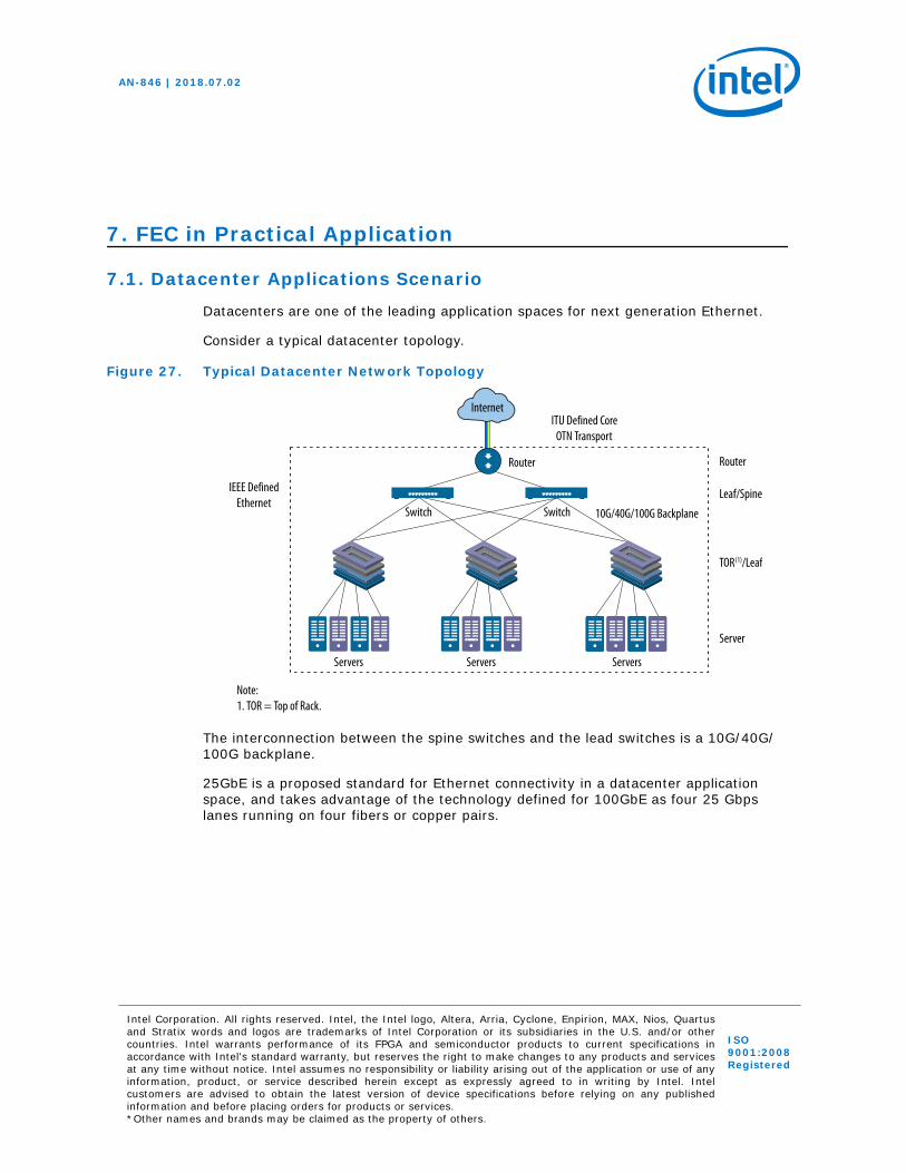
Figure 27. Typical Datacenter Network Topology
IEEE DefinedEthernet
Router
ITU Defined CoreOTN Transport
Leaf/Spine
TOR(1)/Leaf
Server
Servers
Switch Switch
Internet
10G/40G/100G Backplane
Router
Servers Servers
Note:1. TOR = Top of Rack.
The interconnection between the spine switches and the lead switches is a 10G/40G/100G backplane.
25GbE is a proposed standard for Ethernet connectivity in a datacenter applicationspace, and takes advantage of the technology defined for 100GbE as four 25 Gbpslanes running on four fibers or copper pairs.
AN-846 | 2018.07.02
Intel Corporation. All rights reserved. Intel, the Intel logo, Altera, Arria, Cyclone, Enpirion, MAX, Nios, Quartusand Stratix words and logos are trademarks of Intel Corporation or its subsidiaries in the U.S. and/or othercountries. Intel warrants performance of its FPGA and semiconductor products to current specifications inaccordance with Intel's standard warranty, but reserves the right to make changes to any products and servicesat any time without notice. Intel assumes no responsibility or liability arising out of the application or use of anyinformation, product, or service described herein except as expressly agreed to in writing by Intel. Intelcustomers are advised to obtain the latest version of device specifications before relying on any publishedinformation and before placing orders for products or services.*Other names and brands may be claimed as the property of others.
ISO9001:2008Registered
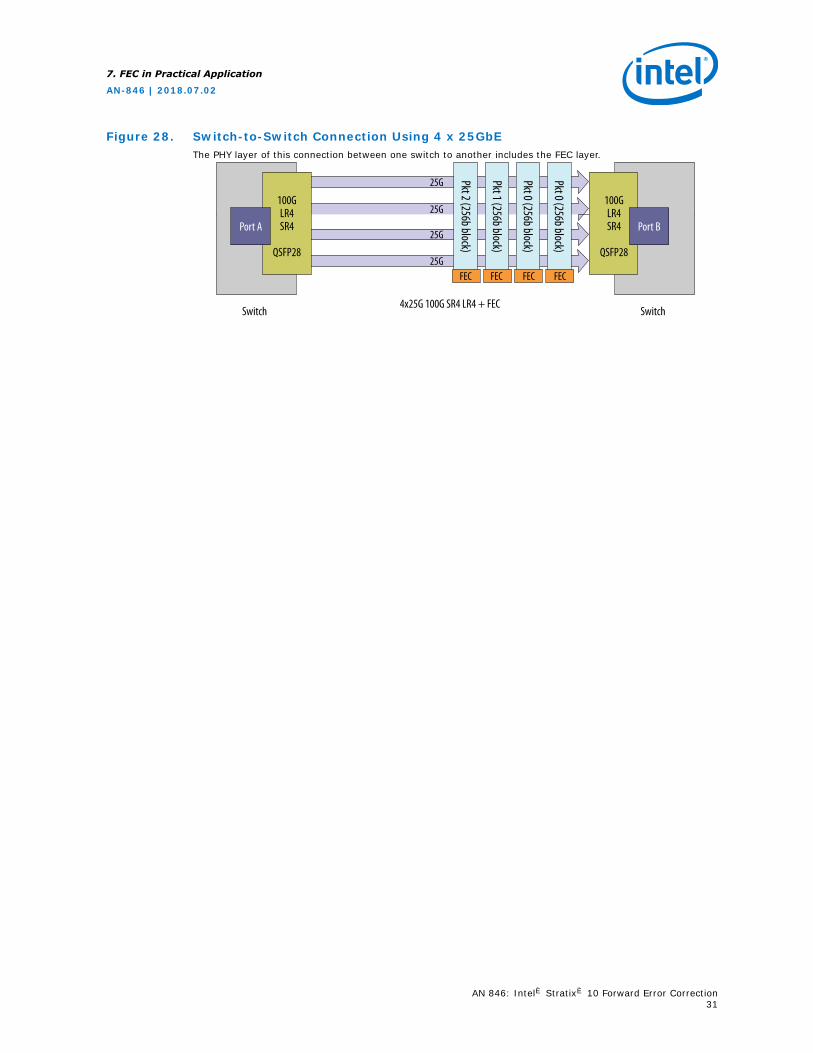
Figure 28. Switch-to-Switch Connection Using 4 x 25GbEThe PHY layer of this connection between one switch to another includes the FEC layer.
100GLR4SR4
QSFP28
100GLR4SR4
QSFP28
Port A Port B
SwitchSwitch4x25G 100G SR4 LR4 + FEC
25G
25G
25G
25GFEC FEC FEC FEC
Pkt 2 (256b block)
Pkt 0 (256b block)
Pkt 0 (256b block)
Pkt 1 (256b block)
7. FEC in Practical Application
AN-846 | 2018.07.02
AN 846: Intel® Stratix® 10 Forward Error Correction31
8. Hardware Results
8.1. Test Design
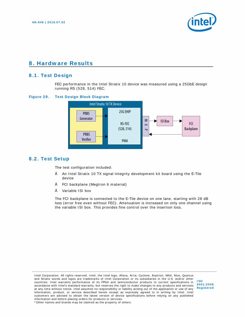
FEC performance in the Intel Stratix 10 device was measured using a 25GbE designrunning RS (528, 514) FEC.
Figure 29. Test Design Block Diagram
Intel Stratix 10 TX Device
PRBSGenerator
PRBSVerifier
25G EHIP
RS-FEC(528, 514)
PMA
M X
P
ISI BoxFCI
Backplane
8.2. Test Setup
The test configuration included:
• An Intel Stratix 10 TX signal integrity development kit board using the E-Tiledevice
• FCI backplane (Megtron 6 material)
• Variable ISI box
The FCI backplane is connected to the E-Tile device on one lane, starting with 28 dBloss (error free even without FEC). Attenuation is increased on only one channel usingthe variable ISI box. This provides fine control over the insertion loss.
AN-846 | 2018.07.02
Intel Corporation. All rights reserved. Intel, the Intel logo, Altera, Arria, Cyclone, Enpirion, MAX, Nios, Quartusand Stratix words and logos are trademarks of Intel Corporation or its subsidiaries in the U.S. and/or othercountries. Intel warrants performance of its FPGA and semiconductor products to current specifications inaccordance with Intel's standard warranty, but reserves the right to make changes to any products and servicesat any time without notice. Intel assumes no responsibility or liability arising out of the application or use of anyinformation, product, or service described herein except as expressly agreed to in writing by Intel. Intelcustomers are advised to obtain the latest version of device specifications before relying on any publishedinformation and before placing orders for products or services.*Other names and brands may be claimed as the property of others.
ISO9001:2008Registered
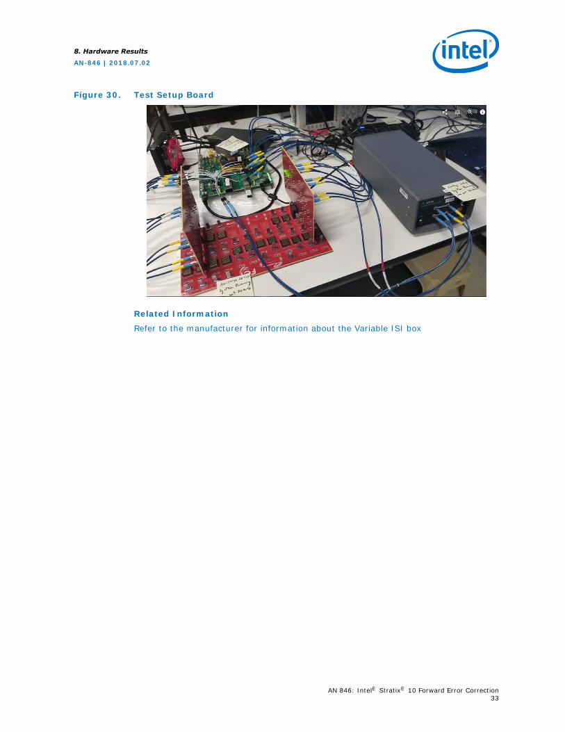
Figure 30. Test Setup Board
Related Information
Refer to the manufacturer for information about the Variable ISI box
8. Hardware Results
AN-846 | 2018.07.02
AN 846: Intel® Stratix® 10 Forward Error Correction33
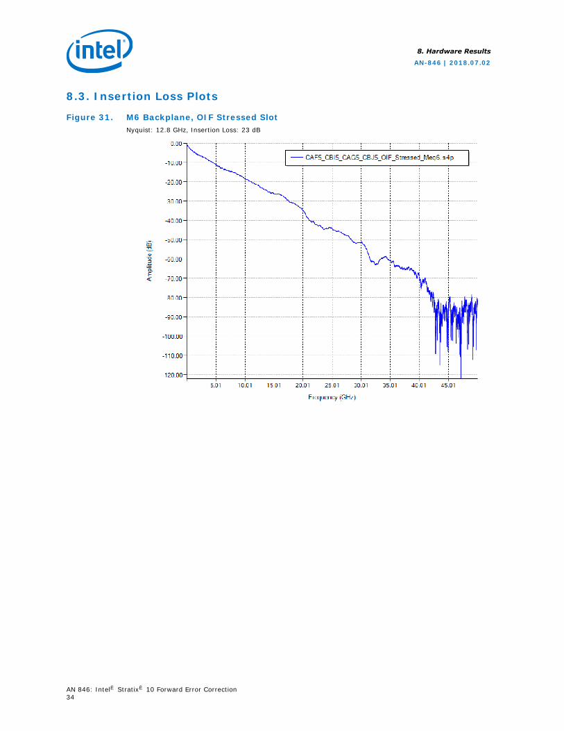
8.3. Insertion Loss Plots
Figure 31. M6 Backplane, OIF Stressed SlotNyquist: 12.8 GHz, Insertion Loss: 23 dB
8. Hardware Results
AN-846 | 2018.07.02
AN 846: Intel® Stratix® 10 Forward Error Correction34
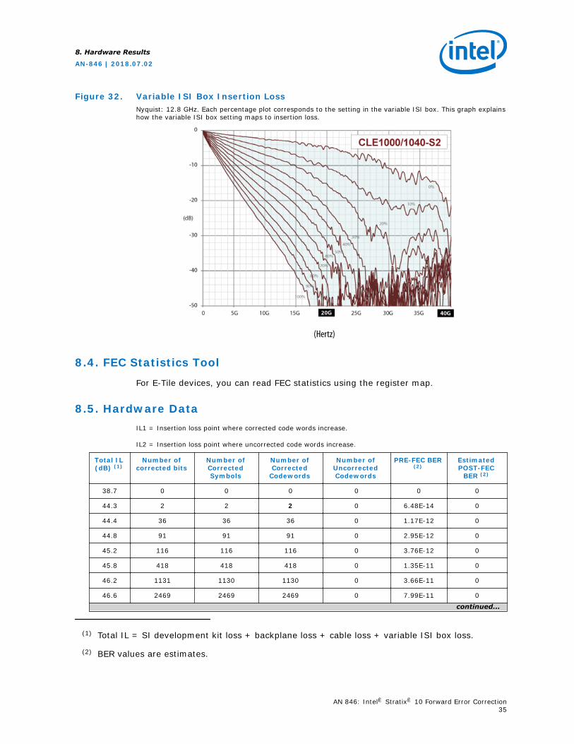
Figure 32. Variable ISI Box Insertion LossNyquist: 12.8 GHz. Each percentage plot corresponds to the setting in the variable ISI box. This graph explainshow the variable ISI box setting maps to insertion loss.
(Hertz)
8.4. FEC Statistics Tool
For E-Tile devices, you can read FEC statistics using the register map.
8.5. Hardware DataIL1 = Insertion loss point where corrected code words increase.
IL2 = Insertion loss point where uncorrected code words increase.
Total IL(dB) (1)
Number ofcorrected bits
Number ofCorrectedSymbols
Number ofCorrected
Codewords
Number ofUncorrectedCodewords
PRE-FEC BER(2)
EstimatedPOST-FEC
BER (2)
38.7 0 0 0 0 0 0
44.3 2 2 2 0 6.48E-14 0
44.4 36 36 36 0 1.17E-12 0
44.8 91 91 91 0 2.95E-12 0
45.2 116 116 116 0 3.76E-12 0
45.8 418 418 418 0 1.35E-11 0
46.2 1131 1130 1130 0 3.66E-11 0
46.6 2469 2469 2469 0 7.99E-11 0
continued...
(1) Total IL = SI development kit loss + backplane loss + cable loss + variable ISI box loss.
(2) BER values are estimates.
8. Hardware Results
AN-846 | 2018.07.02
AN 846: Intel® Stratix® 10 Forward Error Correction35
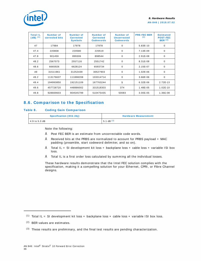
Total IL(dB) (1)
Number ofcorrected bits
Number ofCorrectedSymbols
Number ofCorrected
Codewords
Number ofUncorrectedCodewords
PRE-FEC BER(2)
EstimatedPOST-FEC
BER (2)
47 17984 17978 17978 0 5.83E-10 0
47.4 220808 220580 220519 0 7.13E-09 0
47.8 901459 899306 898544 0 2.91E-08 0
48.2 2567073 2557116 2551742 0 8.31E-08 0
48.6 6665926 6628124 6593734 0 2.15E-07 0
49 31511961 31252439 30527903 0 1.02E-06 0
49.2 113176637 111898208 103314714 0 3.66E-06 0
49.4 194993850 192151109 167763244 1 6.32E-06 2.72E-13
49.6 457728720 448886002 331518303 374 1.48E-05 1.02E-10
49.8 928669603 904545799 510475435 50083 3.00E-05 1.36E-08
8.6. Comparison to the Specification
Table 8. Coding Gain Comparison
Specification (802.3bj) Hardware Measurement
4.9 to 5.3 dB 5.1 dB (3)
Note the following:
• Post FEC BER is an estimate from uncorrectable code words.
• Received bits at the PRBS are normalized to account for PRBS payload + MACpadding (preamble, start codeword delimiter, and so on).
• Total IL = SI development kit loss + backplane loss + cable loss + variable ISI boxloss.
• Total IL is a first order loss calculated by summing all the individual losses.
These hardware results demonstrate that the Intel FEC solution complies with thespecification, making it a compelling solution for your Ethernet, CPRI, or Fibre Channeldesigns.
(1) Total IL = SI development kit loss + backplane loss + cable loss + variable ISI box loss.
(2) BER values are estimates.
(3) These results are preliminary, and the final test results are pending characterization.
8. Hardware Results
AN-846 | 2018.07.02
AN 846: Intel® Stratix® 10 Forward Error Correction36
8.7. References
For more information about forward error correction, refer to the following resources:
• J. Schrum, YouTube video : "Error Detection and Correction 3: Forward ErrorCorrection," 2016. [Online].
• A. Davis, EE Times : "Design How-To Forward Error Correction," 1998. [Online].
• N. R. Wagner, "The Laws of Cryptography: The Hamming Code for ErrorCorrection," [Online].
• Optical Transport Network (OTN) Tutorial. ITU. [Online].
Related Information
• Error Detection and Correction 3: Forward Error Correction
• Design How-To Forward Error Correction
• The Laws of Cryptography: The Hamming Code for Error Correction
• Optical Transport Network (OTN) Tutorial
8. Hardware Results
AN-846 | 2018.07.02
AN 846: Intel® Stratix® 10 Forward Error Correction37
9. Document Revision History for AN 846: Intel Stratix 10Forward Error Correction
DocumentVersion
Changes
2018.07.02 Initial release.
AN-846 | 2018.07.02
Intel Corporation. All rights reserved. Intel, the Intel logo, Altera, Arria, Cyclone, Enpirion, MAX, Nios, Quartusand Stratix words and logos are trademarks of Intel Corporation or its subsidiaries in the U.S. and/or othercountries. Intel warrants performance of its FPGA and semiconductor products to current specifications inaccordance with Intel's standard warranty, but reserves the right to make changes to any products and servicesat any time without notice. Intel assumes no responsibility or liability arising out of the application or use of anyinformation, product, or service described herein except as expressly agreed to in writing by Intel. Intelcustomers are advised to obtain the latest version of device specifications before relying on any publishedinformation and before placing orders for products or services.*Other names and brands may be claimed as the property of others.
ISO9001:2008Registered