an adaptive data link layer protocol for wireless atm networks
TRANSCRIPT
An Adaptive Data Link Layer Protocol for Wireless
ATM Networks
by
Sunil Jagannath
B.E., University of Mysore, India, 1994
Submitted to the Department of Electrical Engineering and ComputerScience and the Faculty of the Graduate School of the University of
Kansas in partial fulfillment of the requirementsfor the degree of Master of Science.
Professor in Charge
Committee Members
Date thesis accepted

Dedicated to
My Parents, Dasarao and Chitra Jagannath for their encouragement and support and to
my late grandparents Hari and Sarojini Balaram Rao whose memory will be with me
always.

Acknowledgments
I would like to thank Dr. Victor Frost, my advisor and committee chair for his
patience and encouragement throughout my study here at KU. His guidance and advice
have been invaluable throughout the course of this work. I would also like to thank
Dr. Sam Shanmugan for giving me the opportunity to come here to KU and work on
the RDRN project. It has been a tremendous learning experience and I am grateful for
it. I would also like to thank him and Dr. Glenn Prescott for serving on my masters
committee.
Lastly I would like to acknowledge my colleagues on the project Stephen Bush and
Ricardo Sanchez. I have enjoyed the many discussions we have had and working with
them has benefitted me greatly.

Abstract
The last few years has seen a growing demand for wireless integrated network services.
This surge of interest is due to several factors such as the increased availability of wire-
less personal computing, entertainment and communication devices, liberalization of
spectrum allocation procedures and advances in digital signal processing and radio mo-
dem technologies. This growing interest has motivated several researchers to examine
the feasibility of extending the ATM paradigm from the wireline to the wireless do-
main. This is a non trivial task that poses several technical challenges. Most of these
challenges arise from the inherent differences between the wired and wireless media
and from user mobility in the wireless world. The work in this thesis presents solu-
tions for some of these problems and is part of a complete wireless integrated network
solution.
One of the main problems with wireless ATM is overcoming the unreliability of the
wireless link in order to maintain quality of service requirements over the wireless por-
tion of the network. This work solves this problem through an adaptive data link layer
protocol. The protocol distinguishes between delay-sensitive and delay-insensitive traf-
fic and uses go-back-n ARQ for error recovery of the delay-insensitive traffic. Delay-
sensitive traffic received with errors is dropped. In addition a simple channel state
estimation algorithm is implemented at the data link layer to detect changes in the
channel state between low error rate and high error rate conditions. This state informa-
4

tion is used to adapt the wireless frame length and retransmission mechanism in order
to maximize the throughput under all error rate conditions.
Performance measurements of the adaptive data link layer protocol under various
test scenarios are also presented. The performance measurements indicate the useful-
ness of each of the adaptive features. The conclusions that can be drawn from this work
are listed and some suggestions for future work are also provided.

Contents
1 Introduction 1
1.1 Motivation and some History . . . . . . . . . . . . . . . . . . . . . . . 2
1.2 Our Contribution . . . . . . . . . . . . . . . . . . . . . . . . . . . . . 3
1.3 Organization of this Thesis . . . . . . . . . . . . . . . . . . . . . . . . 4
2 Background and Related Work 6
2.1 Wireless ATM - rationale and challenges . . . . . . . . . . . . . . . . . 6
2.2 Overview of RDRN . . . . . . . . . . . . . . . . . . . . . . . . . . . . 10
2.3 Other Wireless ATM Systems . . . . . . . . . . . . . . . . . . . . . . . 12
2.3.1 SWAN - Bell Laboratories . . . . . .. . . . . . . . . . . . . . 12
2.3.2 BAHAMA - Bell Laboratories . . . .. . . . . . . . . . . . . . 13
2.3.3 WATMnet - NEC C&C Research Laboratories . . . . . . . . . 13
2.3.4 Cambridge-Olivetti Research Laboratories .. . . . . . . . . . 14
2.3.5 Carleton University . . .. . . . . . . . . . . . . . . . . . . . . 14
2.4 Need for an Adaptive Data Link Control Protocol . . . . . . . . . . . . 15
2.4.1 Data Link Control in other Wireless ATM Networks . . . . . . 16
2.4.2 Data Link Control in Packet Radio Networks. . . . . . . . . . 20
2.5 The Adaptive Data Link Control Protocol for RDRN . . . . . . . . . . 21
i
2.6 Background on Link State Determination and Pre-emptive Retransmis-
sion Mechanisms . . . . . . . . . . . . . . . . . . . . . . . . . . . . . 22
3 The RDRN Adaptive Data Link Layer Protocol 24
3.1 The RDRN network architecture . . . . . . . . . . . . . . . . . . . . . 24
3.1.1 Adaptive ATM Layer . .. . . . . . . . . . . . . . . . . . . . . 27
3.1.2 SAR layer .. . . . . . . . . . . . . . . . . . . . . . . . . . . . 28
3.1.3 Wireless ATM Interface Layer . . . .. . . . . . . . . . . . . . 29
3.2 The adaptive data link control layer . . . . . . . . . . . . . . . . . . . 29
3.2.1 Wireless Frame Structure. . . . . . . . . . . . . . . . . . . . . 30
3.2.2 Frame Types Used . . .. . . . . . . . . . . . . . . . . . . . . 33
3.3 Protocol Operation and Implementation . . . . . . . . . . . . . . . . . 36
3.3.1 Private Data Structures .. . . . . . . . . . . . . . . . . . . . . 36
3.3.2 Protocol Operation . . .. . . . . . . . . . . . . . . . . . . . . 40
3.4 Link State Estimation . . . . . .. . . . . . . . . . . . . . . . . . . . . 42
3.5 Adaptive Frame Length . . . . . . . . . . . . . . . . . . . . . . . . . . 48
3.6 Pre-emptive Retransmissions . . . . . . . . . . . . . . . . . . . . . . . 49
4 Performance Measurements 52
4.1 Setup used for Performance Measurements . . . . . . . . . . . . . . . 52
4.1.1 Random Error Generator. . . . . . . . . . . . . . . . . . . . . 53
4.2 Optimal Frame Size for Good and Bad States. . . . . . . . . . . . . . 54
4.3 Effect of Adaptive Frame Lengths on Throughput . .. . . . . . . . . . 56
4.4 Effect of NCopy Mechanism on Throughput. . . . . . . . . . . . . . 58
4.5 Effect of the Combination of Adaptive Frame Lengths and NCopy on
Throughput . . . .. . . . . . . . . . . . . . . . . . . . . . . . . . . . 61

5 Conclusions 64
5.1 Summary of Results and Conclusions . . . . . . . . . . . . . . . . . . 64
5.2 Some Suggestions for Future Work . . . . . .. . . . . . . . . . . . . . 65

List of Tables
2.1 Comparison of various DLC Schemes. . . . . . . . . . . . . . . . . . . 19
iv
List of Figures
2.1 Typical wireless enhanced ATM protocol stack . . . . . . . . . . . . . 10
3.1 High-Level RDRN Architecture . . . . . . . . . . . . . . . . . . . . . 25
3.2 EN Network Architecture . . . . . . . . . . . . . . . . . . . . . . . . . 26
3.3 RN Network Architecture . . . . . . . . . . . . . . . . . . . . . . . . . 27
3.4 Wireless Frame Format . . . . . . . . . . . . . . . . . . . . . . . . . . 31
3.5 Control Field Formats . . . . . . . . . . . . . . . . . . . . . . . . . . . 34
3.6 S Frame Control Field Formats . . . . . . . . . . . . . . . . . . . . . . 35
3.7 U Frame Control Field Formats . . . . . . . . . . . . . . . . . . . . . . 36
3.8 Contents of the Control Block Structure . . . . . . . . . . . . . . . . . 37
3.9 Contents of the aps info structure . . . . . . . . . . . . . . . . . . . . . 39
3.10 Effect of Large Synchronization Delays on State Estimation . . . . . . 45
3.11 State Estimation Control Field Formats . . .. . . . . . . . . . . . . . 46
3.12 Flow Diagram for Channel Estimation Process. . . . . . . . . . . . . . 47
3.13 Flow Diagram for Channel Estimation Process (contd.) . . . . . . . . . 51
4.1 Variation of Throughput versus Frame Size when the Channel is in the
Good State. . . . . . . . . . . . . . . . . . . . . . . . . . . . . . . . . 55
4.2 Variation of Throughput versus Frame Size when the Channel is in the
Bad State. . . . . . . . . . . . . . . . . . . . . . . . . . . . . . . . . . 56
v

4.3 Variation of Throughput without any Adaptive Mechanisms. . . . . . . 58
4.4 Variation of Throughput with Adaptive Length Mechanism. . . . . . . . 59
4.5 Variation of Throughput with 2-Copy Mechanism. . .. . . . . . . . . . 60
4.6 Variation of Throughput with 3-Copy Mechanism. . .. . . . . . . . . . 61
4.7 Variation of Throughput with Adaptive Length and 2-Copy Mechanisms. 62
4.8 Variation of Throughput with Adaptive Length and 3-Copy Mechanisms. 62
4.9 Variation of Throughput with Adaptive Length and 2-Copy vs Adaptive
Length and 3-Copy Mechanisms. . . . . . . . . . . . . . . . . . . . . . 63

Chapter 1
Introduction
The last few years has seen an explosion in wireline broadband networking technolo-
gies. This has been driven by an increased user demand for video teleconferencing,
image applications, world wide web access and other multimedia applications as well
as advancements in key enabling technologies such as high-speed digital transmission
(optical fiber), digital signal processing and high-speed integrated circuits. In this time
Asynchronous Transfer Mode (ATM) has emerged as the front runner in integrated
telecommunication technologies. ATM provides high-speed transfer, integration of
traffic types, flexible bandwidth allocation and service type selection for a range of
applications, efficient multiplexing of data from bursty data/multimedia sources and
simplified network management. It is rapidly becoming a worldwide standard and has
moved from concept to reality in the space of a few years.
Wireless personal communication networks have also emerged as an important field
of activity in telecommunications. This surge of interest is due to several factors such
as the increased availability of wireless personal computing, entertainment and com-
munication devices, liberalization of spectrum allocation procedures and advances in
digital signal processing and radio modem technologies. While these systems have
1
initially focused only on voice and primitive packet data applications, it is recognized
that they will have to evolve toward supporting a wider range of applications involving
video and multimedia. The increased dependence on networking for business, recre-
ation and communications, the growing demand for multimedia applications together
with a human desire for mobility and freedom from office-only or home-only comput-
ing constraints makes a strong argument for wireless integrated networks.
1.1 Motivation and some History
The growing interest in wireless integrated networks has motivated several researchers
to examine the feasibility of extending the ATM paradigm from the wireline to the
wireless domain. This is a non trivial task that poses several technical challenges. Many
of these challenges arise from the inherent differences between the wired and wireless
media. ATM was designed for a time-invariant, reliable medium where bandwidth is
not a significant constraint. However, the wireless channel is usually time-varying with
a high bit error rate and limited bandwidth. The ATM protocol provides no built-in
mechanism to recover from errors or cell losses due to problems with the underlying
transport medium. Thus one of the requirements for making wireless ATM a reality is
a method of compensating for the low reliability of the wireless channel. The obvious
solution to this problem is to employ a protocol at the data link level that handles the
error recovery and control over the wireless channel and provides the ATM layer with
a more reliable transport medium. This work presents such a protocol.
In addition, a medium access protocol is needed to control usage of the wireless
medium and allow channel sharing by multiple terminals. Some enhancements are also
needed at the ATM level to support terminal mobility within a fixed ATM network.
In particular issues like handoff control, location management and routing/quality of
2
service (QOS) control need to be addressed.
The first proposals for wireless ATM appeared in the literature in 1992. Since then
there has been considerable work done to find solutions to the problems described
above. Architectures and system designs for complete wireless ATM systems have
been proposed and by the time of this writing, several of these have been developed
into working prototype systems. These efforts have shown that the concept of wireless
ATM is feasible and desirable.
1.2 Our Contribution
There have been some data link layer protocols for wireless ATM networks proposed
by other researchers in the literature [2, 12, 26]. The purpose of all these schemes is
to perform error control and recovery over the wireless portion of the network. Almost
all of these schemes use automatic repeat request (ARQ) with selective repeat supple-
mented by forward error correction coding. These techniques have high complexity
and can only be implemented efficiently using special purpose hardware. Thus while
they are quite efficient, they lack flexibility.
Wireless channels are usually time-varying and the channel bit error rates vary as
the surrounding environment changes. However all of the protocols developed earlier
fail to recognize this characteristic of the wireless medium.
Also most of the protocols in the literature are designed for a pico-cellular, in-
door wireless environment. They focus more on reliability over the air and less on the
throughput performance of the protocol.
This thesis presents an adaptive data link layer protocol for a macro-cellular, mobile
wireless ATM network with link distances of several kilometers. It uses go-back-n
ARQ for error control and allows standard ATM QOS parameters to be extended over
3

the wireless portion of the network. The entire protocol stack has been implemented
in software which makes the system very flexible. It also makes it an ideal test bed
for future research in adaptive wireless networks. Also a simple method is proposed
for channel state estimation at the data link level. This estimate of the channel is used
to adapt the operation of the protocol to the wireless channel conditions, with the aim
of maximizing throughput under all channel conditions. Performance measurements of
the protocol that show the effect of the adaptations on the throughput are also presented.
1.3 Organization of this Thesis
In this section we will describe the organization of the rest of this thesis.
Chapter 2 provides some background information and discusses related work in the
field of data link layer protocols for wireless ATM networks. We start by explaining
the rationale for wireless ATM and some of the challenges in making this concept a
reality. We provide a perspective on wireless ATM and briefly introduce several current
wireless ATM research efforts. We also discuss the need for a data link control protocol
in wireless ATM networks and briefly compare and contrast our scheme with others in
the literature.
Chapter 3 describes our adaptive data link protocol. We present the format of the
wireless frame we have developed and explain the operation of the protocol in detail.
We also explain the method we have adopted for channel state estimation at the data
link layer and where and how we use this information about the estimated channel state.
The rationale behind the adaptive frame lengths and frame retransmission is explained.
Chapter 4 describes the test environment and set up we use to make performance
measurements of our adaptive data link layer protocol. Throughput measurements un-
der various scenarios are presented and the results discussed.
4

Finally chapter 5 gives a summary of this work and states the conclusions we have
drawn. Suggestions for extensions to this work in the future are also made.
5

Chapter 2
Background and Related Work
2.1 Wireless ATM - rationale and challenges
Wireless ATM would appear in theory to be the obvious driving technology behind
tomorrow's wireless integrated network services. However, ATM was designed for an
environment where the hosts do not move and are connected to a switch by a relatively
error-free and high-speed point-to-point wired link - an environment very different from
the wireless one. Hence before we delve deep into the issues of wireless ATM, we
need to explain the rationale behind wireless ATM and what the challenges might be in
implementing it.
ATM is a flexible, scalable technology that is rapidly proliferating the world over. It
promises to be at the core of all future multimedia networks. Thus the first argument in
favour of wireless ATM is homogeneity. Extending the ATM model over the wireless
portion of the network would lead to a homogeneous end-to-end network, simplify-
ing the architecture. It would make the whole network standards based and provide
tether-less extension of a fiber-optic based ATM network in a transparent, seamless and
efficient manner.
6

ATM provides virtual circuits whose quality of service (QOS) parameters are ne-
gotiated at set-up time between the endpoints and the network. Extending this model
of QOS-specifiable Virtual Circuits (VCs) over the wireless portion of the network can
provide many advantages. For example, at the medium access layer, VC numbers can
be used to suitably allocate shared wireless channel resources. Similarly, link-level
error control schemes can be suitably adapted depending on the characteristics of the
individual VC. In other words, VCs with QOS parameters in a wireless ATM network
allow data packets being sent over the air to be meaningfully distinguished and not
treated according to one generic policy.
The use of small fixed size ATM cells over the wireless portion of the network
also affords some advantages. Since wireless links have high bit error rates, using
small packets keeps the packet loss probabilities down to acceptable levels and makes
retransmission-based error control at the link level feasible. This is because the packet
error rate depends on the bit error rate and the packet size and for a given bit error
rate, the packet error rate increases as the packet size increases. Also, the fine-grained
multiplexing provided by ATM cells is well suited to slow-speed wireless links since
it leads to lower delay jitter and queuing delays. In other words, use of ATM cells
over wireless portion provides the advantage of cut-through switching, which cannot
be obtained in IP-based wireless local area networks. This is because the ATM cells
can be switched as soon as they are received instead of having to receive the entire
packet before routing as with IP networks.
The reader should by now be convinced of the need for and advantages of wireless
ATM. However there are still several challenges to be overcome in taking wireless ATM
from concept to reality. These challenges mainly stem from the fundamental differences
between the wireline and wireless environments.
The first of these differences is in the limited bandwidth available in the latter
7

medium. Unlike in wireline communications wherein an increasing user population can
be accommodated by deploying more fiber to connect these users to the network, the
available radio spectrum cannot be arbitrarily expanded. ATM, with its approximately
ten percent header overhead per cell, was designed for bandwidth-rich environments
and effectively trades bandwidth for simplicity in switching. Thus, the limited band-
width of the shared wireless medium can significantly impact the efficiency of wireless
ATM.
The second difference is in the time-varying quality of the wireless link between the
mobile user and the base station. The radio link is subject to several time-varying im-
pairments arising from the user mobility and changes in the surrounding environment,
which cause multi-path propagation, shadow fading and distance-dependent path loss.
These impairments manifest themselves in the form of a time-varying link bit-error rate
(BER), with the BER often too high to meet the needs of the application. Since ATM
assumes the use of a very reliable transport medium, it provides no built-in error control
or recovery mechanisms. Thus the extension of ATM to an error-prone wireless setting
would require additional link-level error control mechanisms.
Inherent user mobility in the wireless environment also poses additional challenges.
First, some extraordinary means must be created to allow users to signal connection
requests before the establishment of the connection. Second, there must be a method
for the network to determine a called mobile user's location prior to establishment of a
connection to that user. Third, a mobile user must be continuously tracked as he moves,
throughout the duration of a connection. In case the user moves out of range of the
currently serving base station, ahandoffmust be made to the next serving base station
in such a way that QOS guarantees are maintained. Efficient handoff is especially
critical in a multimedia setting.
Thus we see that some significant enhancements are needed to adapt ATM to a mo-
8
bile and wireless setting. These enhancements fall into two major categories : mobility
related enhancements at a higher level for radio-independent mobility control functions
and wireless-related enhancements at the lower level to tackle wireless link specific
problems. The main functions of the mobility-related enhancements are : location de-
termination and management to enable mapping mobile users to their current locations;
handoff control for dynamic VC rerouting during user migration; and routing and QOS
control to deal with route changes and optimizations during handoff while maintaining
any required QOS parameters. The main functions of the wireless-related enhance-
ments include : high-speed physical-level transmission and reception, medium access
control for channel sharing by multiple users and data link control to compensate for
the high wireless channel BER. The approach usually adopted is to add new wireless
channel specific physical, medium access control and data link control layers below
the ATM network layer. In addition the baseline ATM network and signaling protocol
are enhanced to support specific mobility related functions such as handoff and QOS
renegotiation in response to changes in channel conditions. Figure 2.1 shows a typical
wireless enhanced ATM protocol stack.
There has been considerable worldwide research activity in the field of wireless
ATM in the last few years. These research efforts have demonstrated that the concept
of wireless ATM is feasible and one which can offer significant advantages. In the next
two subsections, we will present high-level overviews of each of these research projects
and highlight their individual contributions and focus. This will help us better illustrate
where and how our work fits in.
9

USERAPPLICATION
TCP
IP
ATM ADAPTATION LAYER (AAL)
WIRELESS ATM NETWORK
LAYER
LAYER
CUSTOM WIRELESS PHYSICAL
MOBILITY
ENHANCED
ATM
SIGNALLING
WATM DLC LAYER
WATM MAC LAYER (2)
(1)
(1) - Wireless ATM Data Link Control Layer
(2) - Wireless ATM Medium Access Control Layer
Figure 2.1: Typical wireless enhanced ATM protocol stack
2.2 Overview of RDRN
The Rapidly Deployable Radio Networks (RDRN) project is a DARPA funded wireless
ATM research project at the University of Kansas. This work is a part of the RDRN
project. The goal of RDRN is to create an ATM-based wireless communication system
that will be adaptive at both the link and network levels to allow for rapid deployment
and reconfiguration in response to a changing environment. The objective of the archi-
tecture is to use an adaptive point-to-point topology to gain the advantages of ATM for
wireless networks. Possible application areas for RDRN are in battlefield communica-
tions and in disaster relief operations.
Each node in the RDRN system is equipped with a Global Positioning System
(GPS) receiver, a packet radio system used for out-of-band signaling, a phased-array
steerable antenna and a wireless ATM interface to integrate seamlessly with a wide
area ATM network. Digital beamforming is used to create directed beams and allow
10
for spatial reuse of transmission frequencies. Location and call management infor-
mation are passed using the out-of-band packet radio based orderwire network. The
orderwire network thus handles all the pre-connection establishment signaling used to
set up the high-speed ATM data paths. GPS based position updates are also transmit-
ted over the orderwire network and help in tracking mobile nodes. Link distances of
several kilometers between the base station and mobile nodes are being considered.
The base stations in this network also have switching capabilities and hence multiple
wireless hops to a particular mobile destination node as well as transmission between
two wireless nodes entirely over the wireless portion of the network are also possible.
This differs from most other wireless ATM research networks which are essentially
micro-cellular indoor networks with only a wireless last hop.
The use of digital beamforming allows the multiple beams formed by a specific
transmitter to all be of the same center frequency. However, different frequencies are
used on the uplink and downlink directions. Within each beam, a time division multi-
ple access (TDMA) structure is used to partition the total bandwidth between multiple
users. The wireless ATM network supports ATM signaling and makes use of ATM
quality of service parameters at the link level. An adaptive data link layer protocol
is used to perform error control and ameliorate the wireless link impairments. This
adaptive protocol is the focus of this work.
A proof-of-concept RDRN system has been built to demonstrate the key technolo-
gies. Details of this proof-of-concept system can be found in [13]. The operation and
performance analysis of the orderwire subsystem are described in [9] while details of
the RDRN network architecture can be found in [10].
11

2.3 Other Wireless ATM Systems
In this section we will briefly introduce some of the other active wireless ATM research
efforts discussed in the literature. This list is not exhaustive and is intended only to give
the reader an idea of the state of the art in this area. These research projects will be
discussed in more detail with particular emphasis on the data link protocol used in each
project, in the next section.
2.3.1 SWAN - Bell Laboratories
Seamless Wireless ATM Network (SWAN) is an experimental indoor wireless ATM
network being developed at the networked computing research department of Bell Lab-
oratories. It is based on room-sized pico cells and mobile multimedia endpoints. The
network model of SWAN consists of base stations connected by a wired ATM backbone
network and wireless ATM last hops to the mobile hosts. The distinguishing features of
SWAN include low-latency VC rerouting algorithms based on performance-triggered
rebuilds, custom reconfigurable and miniature wireless ATM adapter hardware, and
support for end systems ranging from laptops to dumb multimedia terminals. Mobil-
ity enhanced signaling is done through an ATM connection management function. A
simplified token-passing MAC protocol is used for wireless resource sharing with each
mobile assigned its own channel or radio-port on the base station. The synchronous
data link control (SDLC) protocol is used over the air and a 2-byte CRC code is used
for error detection in VCs using link level retransmission. Mobile hosts and base sta-
tions are embedded with custom-designed ATM adaptor cards. A detailed description
of the SWAN hardware, software and network architecture can be found in [2].
12

2.3.2 BAHAMA - Bell Laboratories
BAHAMA is another wireless ATM LAN/PBX system being developed at Bell Labo-
ratories. The proposed LAN consists of network nodes called Portable Base Stations
(PBSs) providing microcell coverage. BAHAMA employs a concept of ad-hoc net-
working in the layout of the PBS-to-PBS interconnections in that the PBSs can be dis-
tributed in an arbitrary topology to form a backbone network that can be reconfigured
with relative ease. A new wireless ATM VP/VC is introduced whereby a “VPI” corre-
sponds to a particular destination PBS rather than to a virtual path of base stations and
links. Mobility is supported by means of an adaptive homing algorithm. The network
employs a wireless data link layer that provides high reliability based on both ARQ and
FEC. Multiple access is provided by an efficient demand-assignment channel access
protocol called DQRUMA. Details of the network concept and prototyping system can
be found in [12].
2.3.3 WATMnet - NEC C&C Research Laboratories
WATMnet is a prototype wireless ATM system under development at NEC USA's C&C
Research Laboratories, based on their proposed architecture and framework for next-
generation wireless integrated communication networks. The basic idea of their pro-
posed system is to use a standard ATM cell for network-level functions, while adding
a wireless header/trailer on the radio link for wireless-channel specific protocol func-
tions. The system is designed for micro-cellular and pico-cellular environments. A
centrally controlled dynamic TDMA/TDD (Time Division Duplex) protocol is used for
medium access control and a QOS based protocol using error detection and retrans-
mission is used for link level error control. Time-of-expiry (TOE) based queue service
disciplines are also investigated as a mechanism for improving QOS in this scenario.
13

Mobility related functions are handled by suitable mobility support extensions to ATM
signaling/control protocols implemented at the base stations and switches within the
network. Details of the system architecture and protocols can be found in [22].
2.3.4 Cambridge-Olivetti Research Laboratories
An experimental wireless ATM local-area network was built at Cambridge-Olivetti Re-
search Laboratories in 1994. The mobile network consists of a large number of small
transmission pico-cells, each served by a base station. All base stations operate on
the same frequency and are interconnected via the wired ATM network. The unit of
transmission over the wireless link is also the ATM cell with the headers suitably mod-
ified to accommodate QOS and the VPI/VCI field condensed. The protocol used for
medium access control is slotted ALOHA with exponential backoff. The slot size used
is equivalent to an ATM cell size. A 16 bit CRC code is used for error detection and
retransmissions of errored or out of sequence cells are used for error correction. Hand-
over and diversity are also used to try and maintain wireless link performance. The
system architecture and some initial network performance measurements are described
in [20].
2.3.5 Carleton University
The work by researchers at Carleton University and the Canadian Institute of Telecom-
munications Research (CITR) in [14] describes a system architecture for a broadband
indoor wireless digital communications system, capable of transporting ATM at trans-
port bit rates up to about 160Mbps for broadband LANs. Access is via a radio system
within the 20 to 60 GHz range. The multi-access microcellular architecture exploits
millimeter-wave and surface-acoustic-wave (SAW) device technologies. Uplink and
14
downlink share the same frequency in time division duplex (TDD) mode. The multi-
access protocol is based on an adaptive-rate polling scheme, where ATM cells are pack-
aged in 64-byte envelopes. Error control is based on ARQ with selective repeat, sup-
plemented by high rate forward error control coding. Most of the emphasis in this work
seems to be on tackling the radio access layer problems and not much has been said on
mobility related problems.
2.4 Need for an Adaptive Data Link Control Protocol
We have already explained the need for and advantages of wireless ATM and also the
challenges in making it a reality. One of the most significant of these challenges is in
the time-varying impairments on the wireless link. These impairments are caused by
multipath propagation, shadow fading and distance-dependent signal power path loss
arising from inherent user mobility and changes in the surrounding environment (such
as birds in flight, moving tree limbs or passing vehicles). They manifest themselves in
terms of a time-varying BER performance of the wireless link, with the BER often too
high to meet the needs of the application.
ATM was designed for an environment where the hosts do not move and assumes
the transmission medium is a relatively error-free and reliable point-to-point wired link.
It provides no built-in error control or recovery mechanisms and leaves these to the dis-
cretion of higher layer protocols. It must be noted that ATM networks can work in two
modes, viz.,native mode ATMor TCP/IP over ATM. Native mode ATM applications
directly use ATM by means of an adaptation layer while TCP/IP over ATM networks
provide ATM as a transport mechanism for the existing TCP/IP protocol suite. Thus in
native mode ATM networks, any required error control must be done below the ATM
layer. In TCP/IP over ATM networks with more than one wireless hop or with one
15

wireless hop and a large separation between endpoints, the delay incurred in doing end-
to-end error control at the TCP layer can be very large. Thus we see that to adapt ATM
to a wireless environment there is a need for error control and recovery mechanisms
below the ATM layer irrespective of which mode of ATM networking is adopted.
This problem of error control in wireless ATM networks can be tackled at two dif-
ferent levels. At the physical level, intelligent and efficient diversity combining and
modulation techniques can be used to minimize the channel impairments described
above and thus reduce the channel BER. In addition, given a particular channel BER, a
data link control protocol incorporating retransmissions and/or forward error correction
coding can be used for error control at the link level. In this work, we have focussed on
developing such an adaptive data link control protocol. The purpose of this protocol is
to insulate the ATM network layer from wireless channel impairments by retransmis-
sion of erroneous or lost cells before they are passed on to the ATM layer.
2.4.1 Data Link Control in other Wireless ATM Networks
We will now briefly review the link level error control mechanisms used in the wireless
ATM networks introduced earlier. This will give the reader an idea of the various alter-
natives and allow one to compare and contrast our scheme with others in the literature.
SWAN
The SWAN network at Bell Laboratories uses FEC and selective retransmission op-
tionally specified on a per-VC basis at connection set-up, for link level error control.
Synchronous Data Link Control (SDLC) frames are sent over the air with each SDLC
frame containing one or morelink cells.Link cells are either of type ATMLC defined to
carry an encapsulated ATM cell or of type MACSIGLC for MAC-level signaling. All
16

link cells are composed of a fixed 6-byte header, and a body whose contents depend
on the type oflink cell. The fixed 6 byte header consists of 3 bytes of radio port-id
and MAC protocol information and a 3 byte FEC field that uses an (8,4) linear code to
forward error correct the preceding 3 bytes. The body of the ATMLC contains an en-
capsulated ATM cell together with link-level error control information ( a 2 byte CRC
code for VCs using link level retransmission). The first phase implementation of the
SWAN air-interface controller uses fixed 64-byte-sized link cells. This means that there
are 5 wasted bytes for ATMLCs with no link level retransmission and 3 bytes wasted
per ATMLC with link level retransmission, resulting in a total of 11 bytes of overhead
per encapsulated ATM cell. This is in addition to the SDLC framing overhead which
is distributed over the contents of the frame. It also means that there is a much larger
number of wasted bytes for signalinglink cells (which have a smaller payload than the
48 bytes for ATMLCs) with consequent higher MAC-level signaling overhead.
BAHAMA
The designers of the BAHAMA network propose the use of both ARQ and FEC for
link level error control. The air interface in this network carries packets made up of one
or more modified ATM cells. These packets have a CRC code to determine whether
they have been received in error. In addition, packets have an FEC overhead for error
correction without retransmission. For real-time applications FEC alone is used, while
for data applications, FEC operates in conjunction with retransmissions. The GFC
field of the ATM cell header is used for cell sequence numbers. The designers also
propose the use of adaptive error control wherein the amount of error control overhead
is adjusted according to the link performance. However no details of how this will be
implemented are provided.
17
WATMnet
The WATMnet at NEC laboratories uses ARQ with selective repeat for link level error
control. The DLC protocols are applied to both packet-mode ABR services as well as
stream-mode CBR and VBR services with the retransmission schemes matched to the
requirements of the individual service classes. A modified ATM cell is transmitted over
the air with a 4 byte header and 2 byte CRC trailer. The 4 byte header consists of a 2
byte compressed ATM cell header and 2 bytes of wireless channel specific overhead.
The compressed ATM cell header consists of 12 bits of VCI information and 4 bits
of ATM control information such as the payload type indicator (PTI) and cell loss
priority (CLP) bit. The wireless channel specific overhead contains a cell sequence
number for error recovery and fields to enable other wireless network functions such
as service type definition, handoff recovery and cell segmentation. The modified cells
are encapsulated within a dynamic TDMA/TDD framework for medium access control.
For ABR, standard selective repeat ARQ is used on a burst-by-burst basis without time
limits for completion. For CBR and VBR, each retransmission effort lasts till a time
limit that is specified by the application at call set-up time.
Cambridge-Olivetti Laboratories
The experimental wireless ATM LAN at Cambridge-Olivetti Laboratories described
in [20] uses error detection with retransmission for link level error control. Specially
designed variable length medium access control (MAC) frames are transmitted over the
air. The MAC frames consist of an up-stream part and a down-stream part with sepa-
rate acknowledgement and frame control overhead fields for each part. The up-stream
and down-stream parts also contain slots for MAC PDUs and at least one contention
interval, which is used in a slotted ALOHA mode to make reservations in the subse-
18
quent MAC frame. The MAC PDUs contain a header, a modified ATM cell with a
condensed cell header and a 2-byte CRC for error detection over the MAC PDU header
and ATM cell header and payload. The MAC PDU header contains a 4-bit sequence
number and 8-bit reservation request. The cell header contains 8 bits each for VPI and
VCI information and does not contain a header error check (HEC) thus resulting in 6
bytes of header for each 48 byte ATM cell payload. MAC PDUs received with errors
are retransmitted in subsequent frames. More details of the physical layer and MAC
protocol can be found in [19].
Carleton University
In the system described in [14], ATM cells are packaged in 64-byte envelopes. ARQ
with selective repeat supplemented by high-rate forward error control coding is used for
link level error control. For synchronous traffic envelopes, a modified selective repeat
ARQ is used where envelopes not yet corrected after a fixed time delay are discarded.
This satisfies any real-time QOS service requirements.
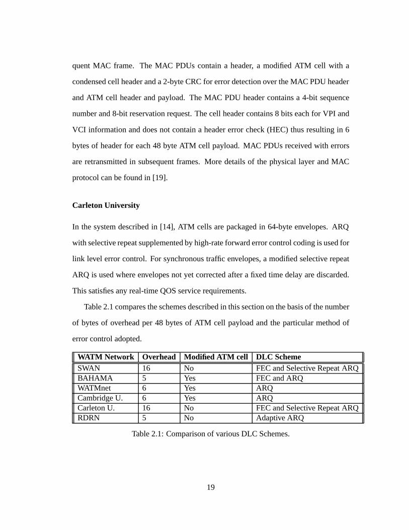
Table 2.1 compares the schemes described in this section on the basis of the number
of bytes of overhead per 48 bytes of ATM cell payload and the particular method of
error control adopted.
WATM Network Overhead Modified ATM cell DLC SchemeSWAN 16 No FEC and Selective Repeat ARQBAHAMA 5 Yes FEC and ARQWATMnet 6 Yes ARQCambridge U. 6 Yes ARQCarleton U. 16 No FEC and Selective Repeat ARQRDRN 5 No Adaptive ARQ
Table 2.1: Comparison of various DLC Schemes.
19
2.4.2 Data Link Control in Packet Radio Networks
Packet radios are based on the notion of applying packet switching to (usually broad-
cast) radio and are capable of supporting mobile users. Packet radio networks are for
the most part based on a store-and-forward operation and are intended to provide data
communications to users located over a broad geographic region. One of the key is-
sues involved in the design of packet radio networks is methods for achieving reliable
communications in the typically noisy radio environment. Much research activity in
the 1980s was devoted to addressing this issue through link level error control. It was
recognized that given the highly variable performance of the digital radio link, retrans-
mission procedures needed to be augmented by FEC coding. The primary issue was
then to determine how to combine ARQ and FEC so as to achieve an adequate level of
link performance [17]. Systems that combine ARQ and FEC error control are referred
to ashybrid ARQsystems and are classified into two categories, namely type-I and
type-II hybrid ARQ. A type-I hybrid ARQ system uses a code which is designed for
simultaneous error detection and correction. The receiver first attempts to correct any
errors in a received code word. If the number of errors in the received code word is too
high and an uncorrectable error pattern is received, the code word is rejected and a re-
transmission is requested. Type-II hybrid ARQ systems adapt themselves to the channel
conditions. When the channel is quiet, only code bits for error detection are included in
each transmission. When the channel becomes noisy, and a retransmission is requested
for a frame received in error, extra code bits are transmitted based on the original mes-
sage and an error-correcting code and are used to correct the original received message.
Several type-I and type-II hybrid ARQ schemes have been proposed and analysed in the
literature based on both block and convolutional codes. In addition, implementations
of several powerful FEC coding schemes have also been developed. [25] summarizes
20

many of these schemes.
However all the schemes introduced above for packet radio networks were devel-
oped for data communications in a broadcast radio environment. They all have complex
implementations and focus more on reliability and less on throughput performance.
Wireless integrated networks require an engineering solution between ARQ and FEC
that will reduce complexity and at the same time satisfy throughput, reliability and QOS
requirements. These requirements change the boundary conditions of the problem and
new research results are needed under these conditions. Thus the earlier work for packet
radio networks can provide direction and serve as the basis for future research but can-
not be directly applied to the wireless ATM networks of today.
2.5 The Adaptive Data Link Control Protocol for RDRN
We will now briefly introduce the novel adaptive data link layer protocol we have de-
veloped for the RDRN network. Details of its design and implementation are given in
the following chapter.
The RDRN network uses error detection with retransmissions for link level error
recovery. Specially designed wireless frames are transmitted over the air, with each
wireless frame either encapsulating one or more ATM cells or carrying link-level con-
trol information. The protocol allows QOS requirements to be specified on a per-VC
basis at setup. Retransmissions are performed only on those VCs designated as car-
rying delay-insensitive information. Frames received in error on VCs designated as
carrying delay-sensitive information are dropped. This scheme thus allows extension
of standard ATM QOS specifications over the wireless portion of the network.
The novel feature of this protocol is the adaptive control it provides. The wireless
link is essentially bimodal with the link error rate being either high or low. We recog-
21

nize that when the error rate is low, the throughput can be maximized by encapsulating
several ATM cells within each wireless frame. However when the link error rate is
high, most frames will be received in error and it would be best to send only one cell in
each frame. Also, the number of frames to be retransmitted in the high error rate state
may be reduced by transmitting multiple copies of each frame at a time, instead of just
one copy (this scheme has been referred to in the literature as the pre-emptive retrans-
mission orn-copymechanism). An estimate of the link state can be made by taking the
ratio of the number of frames received with and without errors in a certain time period
and setting a suitable threshold. Thus this protocol adapts itself to the prevailing link
conditions and attempts to maximize throughput under all link conditions.
Another significant feature of this protocol is its simplicity. The entire protocol
stack including the segmentation and reassembly functions, data link control functions
and medium access control functions has been implemented in software. This gives us
a great deal of flexibility allowing us to use the system as a test bed to experiment with
the various adaptive parameters.
2.6 Background on Link State Determination and Pre-
emptive Retransmission Mechanisms
An adaptive automatic-repeat-request (ARQ) scheme similar to our protocol was sug-
gested earlier in the literature in [27]. This scheme also assumes a two-state channel
model and uses an estimate of the channel state to dynamically adapt the ARQ al-
gorithm. A simple count of the number of positive and negative acknowledgements
received is used to estimate the channel state at the transmitter. The protocol proposes
use of regular go-back-N ARQ in the low error rate state and ann-copyscheme in the
22

high error rate state. However, this scheme is most suited only to wireless data com-
munication networks and not for an integrated network with QOS guarantees. This is
because it requires the receiver to send back either a positive or negative acknowledge-
ment for every frame received, which may not be possible to do while satisfying QOS
guarantees for real-time applications in an integrated network. We overcome this prob-
lem in our system by estimating the channel state at the receiver and communicating
this state information back to the transmitter as explained in the next chapter.
The idea of using repeated transmissions to reduce the number of retransmissions
of a full window of frames in a high error rate state has previously been considered in
the literature in [8], [23] and [7]. In all of these schemes, each frame is transmitted
and, if necessary, retransmitted by sending to the receiver multiple copies of this frame
contiguously instead of one single copy. The different schemes differ in the number
of copies of each frame sent in the first transmission attempt and in each subsequent
retransmission. Bruneel and Moeneclaey in [8] have determined the optimum number
of copies to be sent in each attempt based on the block error probability and round-trip
propagation delay. In our system, we adopt then-copymechanism in the high error rate
state and propose to sendn copies of each frame in all transmission and subsequent
retransmission attempts while the system remains in this state. The value ofn depends
on the actual error rate in the high error rate state. The merits of using then-copy
mechanism are discussed in the next chapter. The optimum value forn is estimated
based on a series of experiments, as discussed in chapter 4.
23

Chapter 3
The RDRN Adaptive Data Link Layer
Protocol
3.1 The RDRN network architecture
The RDRN system, as briefly introduced in the previous chapter, consists of two types
of nodes, namely, Edge Nodes (EN) and Remote Nodes (RN). A high-level view of the
RDRN system architecture is depicted in Figure 3.1. ENs are designed either to reside
on the edge of a wired network and provide access to the wireless network or reside en-
tirely within the wireless portion of the network. The EN components include an Edge
Switch (ES) and optionally an ATM switch, a radio handling the ATM-based commu-
nications, a packet radio for the low speed orderwire running a protocol based on X.25
(AX.25), a GPS receiver, a phased array steerable antenna and a processor. Host nodes
or remote nodes (RN) consist of the above, but do not contain an ATM switch. The EN
has the capability of switching ATM cells among connected RNs or passing the cells on
to an ATM switch to wire-based nodes on an ATM wide-area network. Figure 3.2 shows
the high-speed protocol architecture on the EN while Figure 3.3 shows the correspond-
24
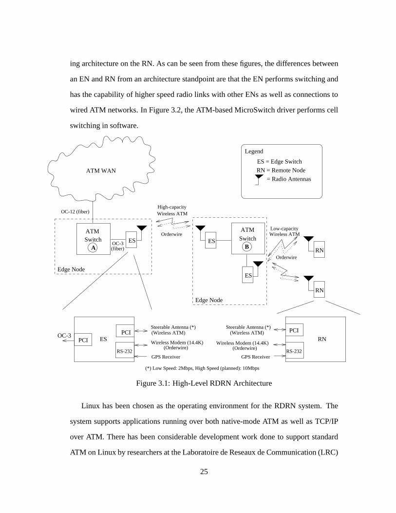
ing architecture on the RN. As can be seen from these figures, the differences between
an EN and RN from an architecture standpoint are that the EN performs switching and
has the capability of higher speed radio links with other ENs as well as connections to
wired ATM networks. In Figure 3.2, the ATM-based MicroSwitch driver performs cell
switching in software.
ES ES
ES
RN
RN
A B
(*) Low Speed: 2Mbps, High Speed (planned): 10Mbps
ATM WAN
OC-3 (fiber)
ATMSwitch
ATM
Switch
Edge Node
Edge Node
PCIPCI ES
OC-3PCI
RN
GPS ReceiverRS-232RS-232
OC-12 (fiber)
Legend
ES = Edge Switch
RN = Remote Node
High-capacityWireless ATM
= Radio Antennas
Low-capacityWireless ATM
Orderwire
Orderwire
GPS Receiver
(Wireless ATM)
Wireless Modem (14.4K)Wireless Modem (14.4K)(Orderwire) (Orderwire)
Steerable Antenna (*) Steerable Antenna (*)(Wireless ATM)
Figure 3.1: High-Level RDRN Architecture
Linux has been chosen as the operating environment for the RDRN system. The
system supports applications running over both native-mode ATM as well as TCP/IP
over ATM. There has been considerable development work done to support standard
ATM on Linux by researchers at the Laboratoire de Reseaux de Communication (LRC)
25

AdaptationManager
ATM-based MicroSwitch driver
To Steerable Antenna To GPS
To Wireless Modem
HDLC driverAdaptive
ATM driverAdaptive
ES Adaptive Stack
SAR driver
Orderwire
Driver
ProtocolRaw Transport
IP over ATM
Device-independent ATM Coordination
ATM Sockets
DaemonLink ManagerPNNI VC Signaling
Daemon
Hardware
User Space
To ATM Switch(Wired Network)
AAL5 pktsAAL0 pkts(raw cells)
Control
Fabric & Call
Kernel Space
Wireless NIC driver
ATM driver (OC-3)
Figure 3.2: EN Network Architecture
at EPFL in Switzerland [3]. In particular, they have developed a BSD-sockets based
application programming interface (API) to support native-mode ATM applications as
well as support for classical IP over ATM (RFC 1577) for TCP/IP based ATM appli-
cations [4]. The Device-independent ATM coordination layer shown in Figures 3.2
and 3.3 is a collection of common data structures and protocol conventions for ATM
on Linux. We have reused the available software from the ATM on Linux distribution
in the RDRN system. Thus the wireless ATM software stack developed for the RDRN
system can be treated just like any other ATM device driver and interfaces into the
standard distribution at the Device-independent ATM Coordination layer as shown in
26
AdaptationManager
OrderwireDriver
ATM Sockets
Device-independent ATM Coordination
Raw TransportIP over ATMProtocol
To Steerable Antenna
Adaptive HDLC driver
SAR driver
Link Manager
DaemonUser Space
Hardware
To GPS
To Wireless Modem
Adaptive ATM driver
RN Adaptive Stack
User ApplicationDaemon
UNI VC Signaling
Kernel Space
Wireless NIC driver
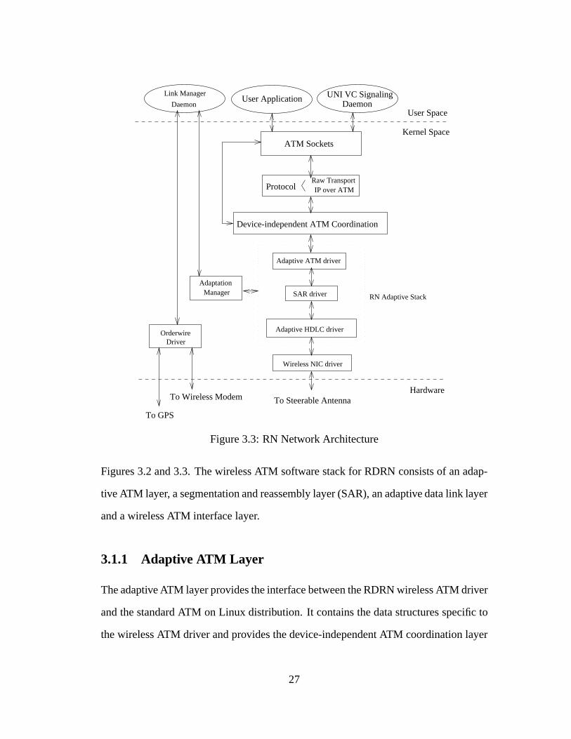
Figure 3.3: RN Network Architecture
Figures 3.2 and 3.3. The wireless ATM software stack for RDRN consists of an adap-
tive ATM layer, a segmentation and reassembly layer (SAR), an adaptive data link layer
and a wireless ATM interface layer.
3.1.1 Adaptive ATM Layer
The adaptive ATM layer provides the interface between the RDRN wireless ATM driver
and the standard ATM on Linux distribution. It contains the data structures specific to
the wireless ATM driver and provides the device-independent ATM coordination layer
27

with standard device-independent entry points to the rest of the wireless software stack.
It thus enables the RDRN wireless stack and the higher layers of the ATM on Linux
distribution to exchange data. The adaptive ATM layer also manages resources on the
wireless stack, keeps track of active VCs and gathers ATM level statistics such as cell
counts, drop counts and so on. While the current implementation is non-adaptive, this
layer can be enhanced to adapt the allocation and management of resources in response
to certain specified parameters or events.
3.1.2 SAR layer
The SAR layer performs ATM segmentation and reassembly functions in software. The
current implementation supports AAL5 and NULL (AAL0) encapsulation types. How-
ever, it must be noted that no AAL is precluded from use. The SAR layer performs one
complete segmentation at a time and allows concurrent reassembly on upto 1024 VCs.
For AAL5 traffic on transmit, the SAR layer receives a protocol data unit (PDU) from
the device-independent ATM coordination layer through the adaptive ATM layer, per-
forms the CRC calculations and computes the AAL5 trailer bytes. It then segments the
resulting AAL5 PDU into 48 byte chunks and adds the appropriate ATM cell headers
before passing the cells down to the adaptive data link control layer for transmission.
For each VCI channel being reassembled, a reassembly queue is allocated in memory
which is used as the workspace for the reassembly process. For AAL5 traffic, CRC
calculations are performed on the reassembly queue as cells are received. AAL5 PDUs
that are reassembled error-free are passed up to the device-independent layer through
the adaptive ATM driver. A VCI table is used within the SAR layer to store informa-
tion about all active VCs. The SAR layer employs early-packet discard to improve the
efficiency of the reassembly process.
28

3.1.3 Wireless ATM Interface Layer
The wireless ATM interface layer provides the interface between the wireless ATM
software stacks and the radio hardware through the peripheral component interconnect
(PCI) card. There will be one PCI interface card on each host serving either a single
stack on the RN or one or more stacks (one per connection) on the EN. As mentioned
earlier, the RDRN system distinguishes between delay-sensitive and delay-insensitive
traffic based on the VC identifier, with delay-sensitive traffic being given higher priority.
The wireless ATM interface layer maintains two service queues, one for delay-sensitive
traffic and the other for delay-insensitive traffic. Wireless frames are handed down to
the wireless ATM interface layer from the data link control layer for transmission and
are added to one of the two queues depending on the frame type. Data is removed
from the queues by the wireless ATM interface hardware with the delay-sensitive traffic
queue being serviced more frequently.
3.2 The adaptive data link control layer
The RDRN system uses error detection with retransmission for link level error recov-
ery. ATM cells transmitted over the air are encapsulated within a specially designed
wireless frame. The protocol allows standard ATM QOS requirements to be extended
over the wireless portion of the network by distinguishing between VCs carrying delay-
sensitive traffic like voice and video from those carrying delay-insensitive traffic like
data. Frames carrying delay-sensitive traffic received with errors are dropped while
frames carrying delay-insensitive traffic received with errors are retransmitted. The
wireless channel state is estimated based on the ratio of the number of frames received
with and without errors and is assumed to be in either a good state (characterized by a
29

low BER) or a bad state (characterized by a high BER). The wireless frame length is
adapted to the channel state with a larger frame used in the good state and a smaller one
in the bad state. Ann-copymechanism is also used in the bad state to transmit multi-
ple copies of each delay-insensitive traffic frame at a time in order to reduce the total
number of retransmission requests. The protocol attempts to maximize the throughput
under all channel conditions.
The protocol uses a sliding window and a go-back-N ARQ scheme to guarantee
reliability. We have chosen a window size of seven wireless frames. The two ends
of the link maintain send and receive state variables and use a set of timers to detect
losses and resequencing of frames. The software implementation of the sliding win-
dow mechanism has been modeled on the existing Linux implementation of the AX.25
amateur packet radio link layer protocol [16]. The entire protocol including the error
detection coding is implemented in software in the prototype system. This makes the
system flexible and provides us with an ideal test-bed for further research. The rest
of this chapter is devoted to explaining in detail various aspects of the protocol, the
implementation and the adaptive features.
3.2.1 Wireless Frame Structure
The basic approach adopted in our system is to use the standard ATM cell for network
level functions while a wireless header and trailer are added over the radio link for the
wireless channel specific functions like medium access control and data link control.
The header and trailer also include necessary overhead due to channel equalization and
timing at the physical level. The use of a wireless frame over the radio link encapsu-
lating several ATM cells allows this necessary overhead to be spread over a larger data
payload, thus reducing its effect. This is especially important in the wireless context
30

where bandwidth is at a premium. We have decided to retain the standard ATM cell
structure over the wireless link without modifying the ATM cell header in any way or
performing cell header compression. This simplifies the functionality required in the
ENs at the boundary between the wired and wireless networks and reduces their com-
plexity. It also allows cells from multiple VCs to be encapsulated in the same frame, as
long as all the VCs carry traffic with the same QOS requirements. Figure 3.4 shows the
structure of the wireless frame that we have developed for the RDRN system.
fTx
fRx
FLAG
AHDLC
TDMA
(6)
Coding
(3)
(5)
Length
FCSControl
Sequence
P/FDATA
8 16 8
RADIO
FLAG
AHDLC
FLAG
PHY HEADER PHY TRAILER
(4)
(4)
8 8 8 8 8
C/R (1)
FT (1)
Figure 3.4: Wireless Frame Format
The frame format we have adopted is based on the standard high-level data link
control (HDLC) frame. However we have done away with any addressing information
in the frame since a physical-level connection will always exist before any data is sent,
making address information unnecessary. The 8 bit radio flag field is used for bit level
synchronization at the physical layer. The AHDLC flag field in the header and trailer is
the standard HDLC flag and is used for frame delineation at the physical level. Ideally
the radio and AHDLC flags should not be included in a frame at the data link level since
this information is used only at the physical level. However we allocate space in the
frame for these fields at the data link level since this makes the implementation more
efficient.
The RDRN system uses digital beamforming to allow for spatial reuse of the trans-
mission frequencies being used. Two separate frequencies are used, one for the uplink
31

direction and the other for the downlink direction. The fieldsfTx andfRx are used to
denote the particular frequencies being used. Each EN is capable of generating multiple
digitally formed beams to serve RNs. Within each beam, a TDMA structure is used to
support multiple users. The 6 bit TDMA field in the frame is partitioned into two 3 bit
fields, one denoting the beam and the other the TDMA time slot on that beam, for that
connection.
The RDRN data link control protocol retransmits frames containing delay-insensitive
traffic received with errors. Frames containing delay-sensitive traffic that are received
with errors are dropped. The receiver thus needs to distinguish between the two traffic
types from the data in received frames in order to process them correctly. The single bit
frame type (FT) field in the frame is appropriately set on the transmit side and is used
to tell the receiver what type of data the frame contains. A value of 1 is used to indicate
delay-insensitive information while a value of 0 is used to indicate delay-sensitive in-
formation. The single bit command/response (C/R) field is an implementation specific
field used locally within the data link layer. It is used to indicate whether a particular
frame is a command or a response. A response frame is never implicitly acknowledged
by the receiver while a command frame may or may not be implicitly acknowledged.
The DATA field is the payload portion of the frame. It contains a variable number
of encapsulated ATM cells padded to the next word boundary. The number of cells in
the frame depends on the channel conditions with the frame containing a larger number
of cells when the channel BER is low and a fewer number of cells when the BER is
high. The Length field in the frame is used to indicate to the receiver the number of
encapsulated cells a particular received frame contains. We determine the actual values
of the length field for the good state and bad state through experimentation, as presented
in the next chapter.
The control sequence field contains protocol control information such as frame
32
types and transmit and receive sequence numbers. The contents of this field will be
described in more detail in the next section. The frame check sequence (FCS) field
contains a 16 bit error detection code over the data link header and trailer and pay-
load portion of the frame. The current implementation uses a 16 bit checksum similar
to the code used in the TCP/IP protocol stack for error detection. The frame format
also provides scope for experimentation with various enhanced coding schemes involv-
ing additional FEC coding over the data portion of the frame. In such schemes, the
FCS would only apply over the data link header and trailer fields and the 3 bit Coding
field would be used to indicate to the receiver the particular coding scheme used over
the payload portion of the frame. Eight such coding schemes using different types of
FEC codes can be supported with the 3 bit coding field. Experimentation with coding
schemes that use FEC coding for delay-sensitive traffic and a combination of FEC and
ARQ for delay-insensitive traffic are also possible in the future.
3.2.2 Frame Types Used
Wireless frames either carry data as encapsulated ATM cells or convey commands and
responses from one end of the link to the other in order to maintain proper link control.
The control sequence field of the wireless frame identifies the type of frame being
sent and carries any required sequencing information. We use three types of wireless
frames, namely, Information frames (I frames), Supervisory frames (S frames), and
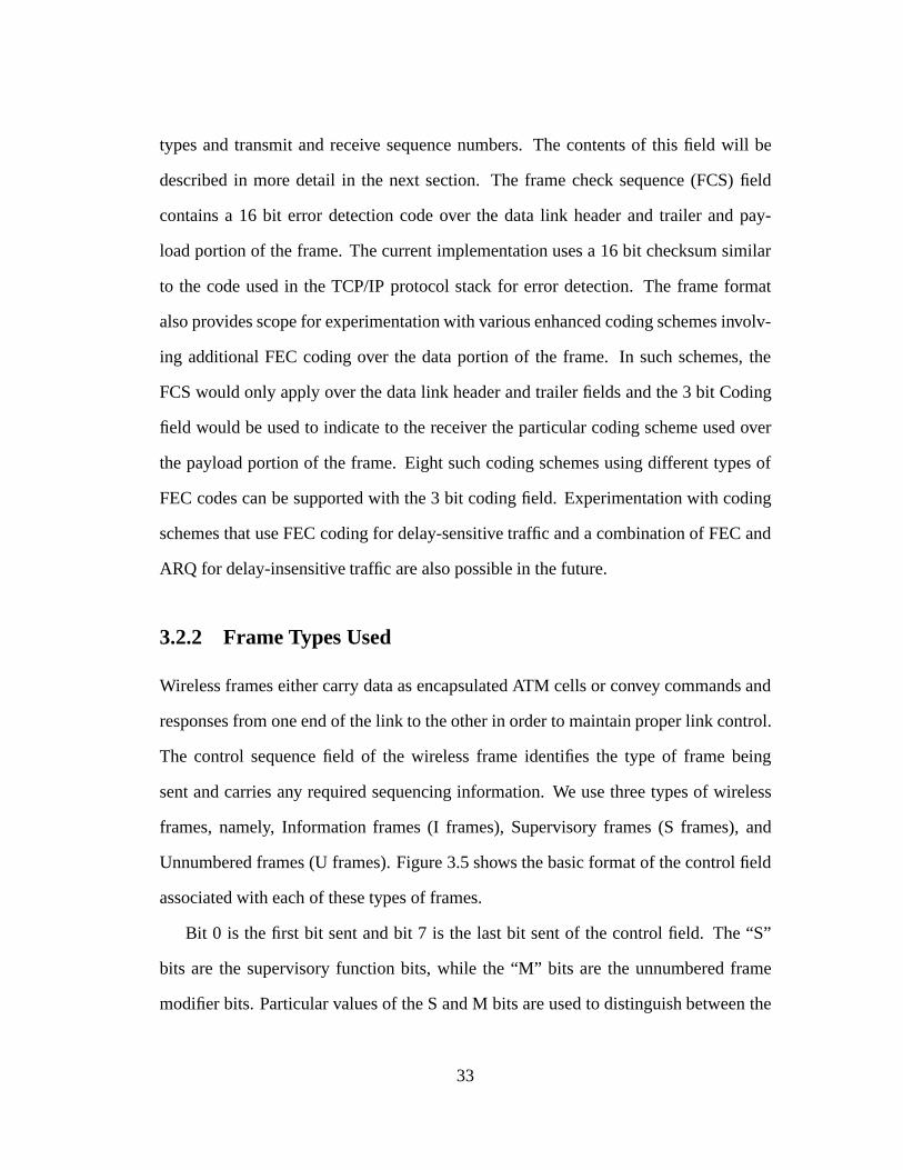
Unnumbered frames (U frames). Figure 3.5 shows the basic format of the control field
associated with each of these types of frames.
Bit 0 is the first bit sent and bit 7 is the last bit sent of the control field. The “S”
bits are the supervisory function bits, while the “M” bits are the unnumbered frame
modifier bits. Particular values of the S and M bits are used to distinguish between the
33
CONTROL-FIELD
TYPE
CONTROL-FIELD BITS
I FRAME
S FRAME
U FRAME
5
M
6 012347
0
1
1
P
P/F
P/F
N(S)N(R)
N(R)
M M 1
S S 0
MM
Figure 3.5: Control Field Formats
different supervisory and unnumbered frames used as shown below. The P/F bit is the
Poll/Final bit. All command frames (C/R bit set) sent with the P/F bit set are implicitly
acknowledged.
The I frame contains data to be transmitted in terms of encapsulated ATM cells.
N(S) is the sender's sequence number for each transmitted frame (bit 1 is the LSB).
N(R) is the receive sequence number and denotes the sequence number of the next ex-
pected received frame (bit 5 is the LSB). N(R) thus serves to acknowledge all received
frames upto N(R)-1. I frame sequence numbers are assigned modulo 8 from 0 to 7 thus
allowing upto 7 outstanding I frames on each connection. S frames provide link control
such as acknowledging or requesting retransmission of I frames. Since S frames do
not have an information field, the sender's send state variable and the receiver's receive
state variable are not changed on receipt of S frames. We use two types of S frames
namely the RR (Receive Ready) frame and the REJ (Reject) frame. The RR frame is
used to acknowledge properly received I frames up to, and including N(R)-1, and to
indicate that the sender of the RR is now able to receive more I frames. The REJ frame
is sent when frames are received out of sequence at the receiver and is used to request
retransmission of I frames starting with frame N(R). Any frames that were sent with a
34

sequence number of N(R)-1 or less are implicitly acknowledged. The reject condition
is cleared by the proper reception of I frames up to the I frame that caused the reject
condition to be initiated. Figure 3.6 shows the S frame control field formats. All S
frames have the bit 0 set to 1 and bit 1 set to 0.
CONTROL-FIELD
TYPE
CONTROL-FIELD BITS
56 0
0
12347
1P/F
N(R)
N(R) 0
Receive Ready (RR)
Reject (REJ)
P/F 0 0 0 1
1
Figure 3.6: S Frame Control Field Formats
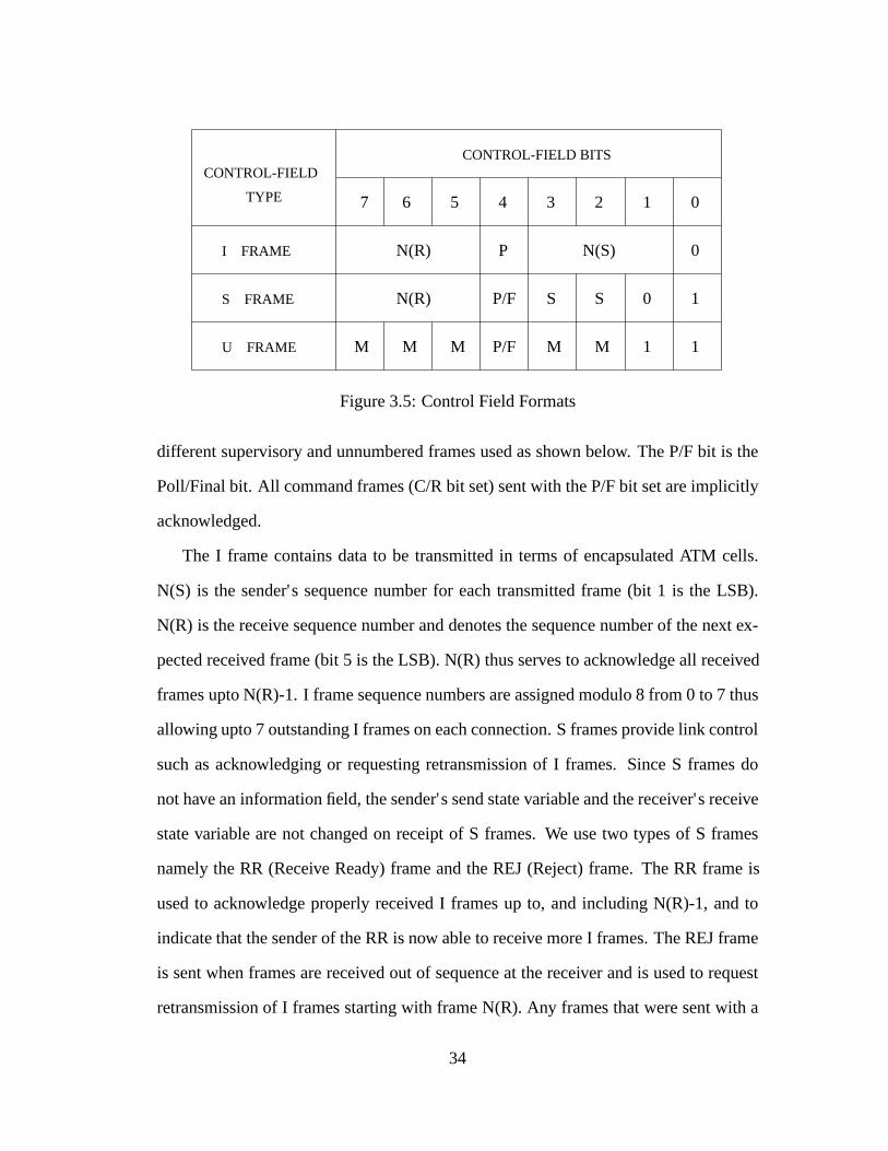
U frames are responsible for maintaining additional control over the link beyond
what is accomplished with S frames. We use 3 types of U frames, namely, link activity
frames (LA), RESET frames and Unnumbered Acknowledgement (UA) frames. LA
frames are sent when there is no traffic observed on the link for a certain period of time.
They are used to elicit a response from the node at the other end of the link and to
determine if the link is indeed still up. The length of the link activity timeout can be
adjusted depending on the application and the nature of traffic the link is carrying. The
current implementation allows LA frames to carry an ATM operations, administration
and maintainance (OAM) cell which can be passed up to the ATM layer for processing.
The RESET frame is sent when a frame is received with a receive sequence number
outside the sending window and is used to recover from such an abnormal operating
condition. The receipt of a RESET frame forces the remote end to reset its state by
reinitializing the send and receive state variables and flushing the queue of frames that
have been transmitted and are awaiting acknowledgements (ack queue). It is necessary
35
to ensure reliable transmission of the RESET frame so that both ends of the link reset
their states together. Thus the sender of the RESET frame enters the reset state and
remains in this state until the remote end sends it an UA frame. All U frames have bits
0 and 1 set to 1. Figure 3.7 shows the U frame control field formats.
CONTROL-FIELD
TYPE
CONTROL-FIELD BITS
56 012
1
347
P/F
P/FLink Activity Frame
Reset Frame
Unnumbered Acknowledgement P/F
0 0 0 0 0 1 1
0 0 0 0 1 1 1
10 1 0 0 1
Figure 3.7: U Frame Control Field Formats
3.3 Protocol Operation and Implementation
3.3.1 Private Data Structures
We use a special data structure which we call acontrol blockto keep track of parameters
specific to each connection such as send and receive state variables, timers and queues.
The contents of thecontrol blockused in the current implementation are shown in
Figure 3.8.
Statedenotes the current state of operation of the data link process.vsandvadenote
the upper and lower bounds of the sending window.vs is incremented every time an I
frame is transmitted andva is incremented whenever an acknowledgement is received
for a previously transmitted I frame.vr is the receive state variable and contains the
36

struct ahdlc cb funsigned char state, modulus;
=� state of the process�=unsigned short vs, vr, va;
=� upper and lower boundsof sending window and thereceive state variable�=
unsigned char condition, backoff;unsigned char n2, n2count;
=� retry count �= 10
unsigned short t1, t2, t3, rtt;=� Timers and the round
trip time �=unsigned short t1timer, t2timer, t3timer;struct sk buff head writequeue;struct sk buff head ackqueue;unsigned char window;struct timer list timer;unsigned int apd;
=� adaptive protocol descriptor 20
- uniquely identifies eachadaptive stack on the EN�=
unsigned short ac t1timer, ac t2timer;unsigned short ac t1, ac t2;struct timer list ac timer;unsigned int ac error count;unsigned int ac frame count;
g;
Figure 3.8: Contents of the Control Block Structure
37
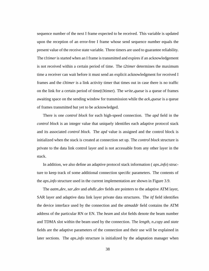
sequence number of the next I frame expected to be received. This variable is updated
upon the reception of an error-free I frame whose send sequence number equals the
present value of the receive state variable. Three timers are used to guarantee reliability.
Thet1timeris started when an I frame is transmitted and expires if an acknowledgement
is not received within a certain period of time. Thet2timerdetermines the maximum
time a receiver can wait before it must send an explicit acknowledgment for received I
frames and thet3timer is a link activity timer that times out in case there is no traffic
on the link for a certain period of time(t3timer). Thewrite queueis a queue of frames
awaiting space on the sending window for transmission while theack queueis a queue
of frames transmitted but yet to be acknowledged.
There is onecontrol blockfor each high-speed connection. Theapd field in the
control blockis an integer value that uniquely identifies each adaptive protocol stack
and its associatedcontrol block. The apd value is assigned and the control block is
initialized when the stack is created at connection set up. Thecontrol blockstructure is
private to the data link control layer and is not accessable from any other layer in the
stack.
In addition, we also define an adaptive protocol stack information (aps info) struc-
ture to keep track of some additional connection specific parameters. The contents of
theaps info structure used in the current implementation are shown in Figure 3.9.
Theaatmdev, sar devandahdlc devfields are pointers to the adaptive ATM layer,
SAR layer and adaptive data link layer private data structures. Theitf field identifies
the device interface used by the connection and theatmaddrfield contains the ATM
address of the particular RN or EN. Thebeamandslot fields denote the beam number
and TDMA slot within the beam used by the connection. Thelength, ncopyandstate
fields are the adaptive parameters of the connection and their use will be explained in
later sections. Theaps info structure is initialized by the adaptation manager when
38

struct am aps info f
unsigned int apd; =� number to uniquelyidentify stack�=
unsigned int itf ; =� interface number for device(assigned by AATM layer)�=
void � aatm dev; =� pointer to ATM-specific info�=
void � sar dev; =� pointer to SAR-specific info�= 10
void � ahdlc dev; =� pointer to DLC-specific info�=
unsigned char atmaddr[ATM ESA LEN];=� ATM address info�=
unsigned int beam; =� Beam info used byTDMA physical layer�=
unsigned int slot; =� Slot info used byTDMA physical layer�=
unsigned int coding; =� Coding info usedby DLC layer �= 20
unsigned int length; =� frame length info usedby DLC layer �=
unsigned int n copy; =� number of consecutivecopies of each frameto be sent in bad state�=
unsigned int state; =� current state of thewireless channel�=
g;
Figure 3.9: Contents of the aps info structure
39

the protocol stack is created at connection set up. It is accessable to all layers of the
protocol stack through theapdand is the glue which allows all the layers of the stack
to talk to each other.
3.3.2 Protocol Operation
The protocol operation differs for delay-sensitive and delay-insensitive traffic. Buffers
of ATM cells are received from the SAR layer on transmit. ATM cells containing real-
time information are encapsulated into wireless frames and directly handed down to
the wireless ATM interface layer for transmission. The number of cells encapsulated in
each frame depends on the current estimate of the channel state and is defined by the
lengthfield of theaps info structure. Error checking is done on the received frames and
frames received with errors are dropped. ATM cells are decapsulated from error-free
frames and passed up to the SAR layer.
When handling delay-insensitive traffic, the protocol operates in one of 3 states,
namely, a connected state, a timer recovery state or a reset state. The connected state
is the normal state of operation. ATM cells received from the SAR layer for transmis-
sion are encapsulated into wireless frames and added to thewrite queue. The sending
window is then checked and as many frames are dequeued from thewrite queueand
transmitted as there is space in the sending window. The send sequence number N(S)
is incremented for each frame sent and thet1timer is started if it is not already run-
ning. Copies of transmitted frames are stored on theack queueuntil they are acknowl-
edged. Acknowledgements are received either as explicit RR frames or piggybacked
on I frames transmitted from the receiver. Since we use a window size of seven, a max-
imum of seven unacknowledged frames will be on theack queueat any given time.
The send sequence number of each I frame received is compared with the current
40
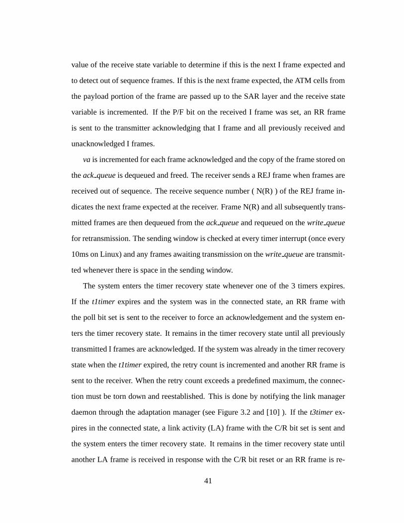
value of the receive state variable to determine if this is the next I frame expected and
to detect out of sequence frames. If this is the next frame expected, the ATM cells from
the payload portion of the frame are passed up to the SAR layer and the receive state
variable is incremented. If the P/F bit on the received I frame was set, an RR frame
is sent to the transmitter acknowledging that I frame and all previously received and
unacknowledged I frames.
va is incremented for each frame acknowledged and the copy of the frame stored on
theack queueis dequeued and freed. The receiver sends a REJ frame when frames are
received out of sequence. The receive sequence number ( N(R) ) of the REJ frame in-
dicates the next frame expected at the receiver. Frame N(R) and all subsequently trans-
mitted frames are then dequeued from theack queueand requeued on thewrite queue
for retransmission. The sending window is checked at every timer interrupt (once every
10ms on Linux) and any frames awaiting transmission on thewrite queueare transmit-
ted whenever there is space in the sending window.
The system enters the timer recovery state whenever one of the 3 timers expires.
If the t1timer expires and the system was in the connected state, an RR frame with
the poll bit set is sent to the receiver to force an acknowledgement and the system en-
ters the timer recovery state. It remains in the timer recovery state until all previously
transmitted I frames are acknowledged. If the system was already in the timer recovery
state when thet1timerexpired, the retry count is incremented and another RR frame is
sent to the receiver. When the retry count exceeds a predefined maximum, the connec-
tion must be torn down and reestablished. This is done by notifying the link manager
daemon through the adaptation manager (see Figure 3.2 and [10] ). If thet3timerex-
pires in the connected state, a link activity (LA) frame with the C/R bit set is sent and
the system enters the timer recovery state. It remains in the timer recovery state until
another LA frame is received in response with the C/R bit reset or an RR frame is re-
41

ceived acknowledging all previously transmitted I frames. If nothing is received, the
link manager daemon is notified to tear down the connection.
The system enters the reset state when a frame is received with receive sequence
number outside the sending window acknowledging a frame that was never sent. This
is an abnormal condition and the only way to recover is to flush theack queueand
reinitialize the sequence numbers, state variables and timers. A RESET frame is also
sent to the remote end to force it to also reset state since both sides of the link must be
synchronized in terms of state variables and sequence numbers for proper protocol op-
eration. The system remains in the reset state until an Unnumbered Acknowledgement
(UA) is received from the remote end confirming that it has also reset its state.
As we mentioned earlier the software implementation of the sliding window mech-
anism for our data link control protocol has been modeled on the existing Linux im-
plementation for AX.25. This implementation was modified to reflect the needs of our
system. The link activity frames containing OAM cells were introduced and reset state
added to the state machine to handle frames received out of order. The addressing
mechanisms and HDLC frame structure needed for AX.25 were removed and the re-
sulting go-back-N implementation integrated with the rest of the RDRN wireless ATM
protocol stack.
3.4 Link State Estimation
We have discussed the basic operation of the adaptive data link protocol. The inter-
esting aspect of this protocol is its ability to adapt the frame length and retransmission
mechanism based on the wireless channel conditions. This requires an estimate of the
wireless channel conditions at frequent intervals. Channel state estimation can be done
either at the physical level or at the data link level. Techniques at the physical level
42

using pilot tone transmissions [18] and signal power measurements [11] have been
discussed in the literature. Yao in [27] uses a simple count of received positive and
negative acknowledgements at the transmitter to estimate the channel state at the link
level.
In the RDRN system, received frames containing delay-sensitive traffic are not ac-
knowledged. Hence a technique that does the channel estimation at the transmitter by
counting acknowledgements would not work when only delay-sensitive traffic was be-
ing transmitted. We overcome this problem by doing the estimation at the receiver and
communicating the state information back to the transmitter. Our estimation method is
based on a ratio of the total number of frames received in a given time period to the
number of frames received in error in the same time period. We use a ratio as opposed
to simple counts to prevent the estimation results from being biased by asymmetric
traffic loads in the uplink and downlink directions.
We maintain a count of received frames and increment this count each time a wire-
less frame is received at the data link layer. We then compute the checksum on the
received frame and pass error free frames up the protocol stack. Frames received with
errors are dropped and an error count is incremented. We assume that the channel is
slowly varying and define an estimation interval over which we assume that the channel
state is unchanged. At the end of this estimation interval we compute an error ratio of
the total number of frames received in this interval to the number of frames received
in error. We also define an upper bound and lower bound error threshold for the esti-
mation process and compare the computed error ratio against these thresholds. If the
state of the channel in the previous interval was estimated to be good and the computed
error ratio is less than both the upper and lower bound error threshold, we estimate that
the channel state for the current interval is bad, else we retain the estimated state as
good. If the state of the channel in the previous interval was estimated to be bad and
43

the computed error ratio is greater than both the upper and lower bound error thresh-
old, we estimate that the channel state for the current interval is good, else we retain
the estimated state as bad. We use two threshold values in the estimation process to
prevent small changes in the error ratio in the region of a single threshold from causing
the estimated state to continually oscillate between the good and bad states. The frame
count and error count are reset at the end of each estimation interval. This channel state
estimation algorithm is illustrated in the flow diagram shown in Figure 3.12. The field
ac t2timer in Figure 3.12 denotes the length of the estimation interval.
One of the main challenges in this method of estimating channel state at the receiver
and communicating this information back to the transmitter is link state synchronization
between the transmitter and receiver. It is important that both ends of the link see the
link as being in the same state. This is achieved by ensuring that any communication
of state information from the receiver back to the transmitter is error-free.
This brings up the question of how the state information must actually be transmit-
ted from receiver back to the transmitter. The RDRN system affords us two possibilities
- one is using specially defined supervisory frames over the high-speed data channel in
the downlink direction while the other is using the out-of-band orderwire channel. Each
alternative has its own advantages and disadvantages. One of the problems with using
the high-speed data channel is that reliably communicating information back to the re-
ceiver in the high-error state may be difficult. Measurements of packet transfer times
over the orderwire have produced values of the order of several hundred milliseconds.
Such large link state synchronization delays between the transmitter and receiver would
make the adaptation to channel state too slow and ineffective. The timing diagram in
Figure 3.10 illustrates this point.
Initially (at time 1) both the transmitter and receiver see the channel as being in
the good state. At time 2, the receiver estimates the channel state to have become bad
44
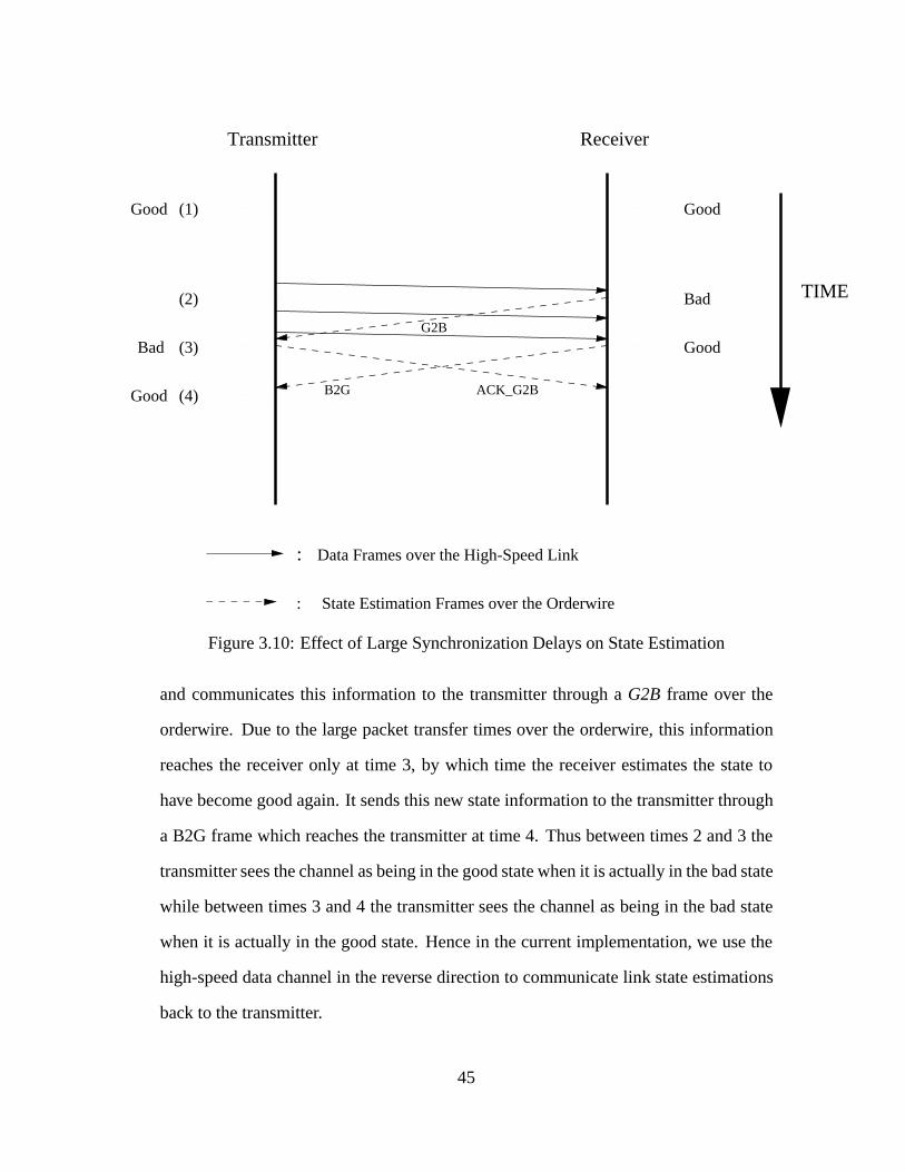
Transmitter Receiver
Good
Good
Bad
Good
Bad
Good
(1)
(2)
(3)
(4)
G2B
ACK_G2BB2G
TIME
: Data Frames over the High-Speed Link
: State Estimation Frames over the Orderwire
Figure 3.10: Effect of Large Synchronization Delays on State Estimation
and communicates this information to the transmitter through aG2B frame over the
orderwire. Due to the large packet transfer times over the orderwire, this information
reaches the receiver only at time 3, by which time the receiver estimates the state to
have become good again. It sends this new state information to the transmitter through
a B2G frame which reaches the transmitter at time 4. Thus between times 2 and 3 the
transmitter sees the channel as being in the good state when it is actually in the bad state
while between times 3 and 4 the transmitter sees the channel as being in the bad state
when it is actually in the good state. Hence in the current implementation, we use the
high-speed data channel in the reverse direction to communicate link state estimations
back to the transmitter.
45
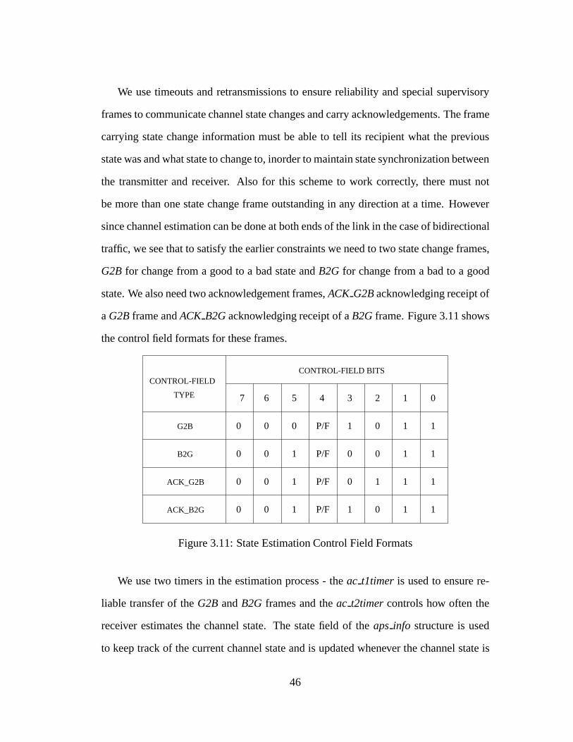
We use timeouts and retransmissions to ensure reliability and special supervisory
frames to communicate channel state changes and carry acknowledgements. The frame
carrying state change information must be able to tell its recipient what the previous
state was and what state to change to, inorder to maintain state synchronization between
the transmitter and receiver. Also for this scheme to work correctly, there must not
be more than one state change frame outstanding in any direction at a time. However
since channel estimation can be done at both ends of the link in the case of bidirectional
traffic, we see that to satisfy the earlier constraints we need to two state change frames,
G2B for change from a good to a bad state andB2G for change from a bad to a good
state. We also need two acknowledgement frames,ACK G2Backnowledging receipt of
aG2Bframe andACK B2Gacknowledging receipt of aB2Gframe. Figure 3.11 shows
the control field formats for these frames.
CONTROL-FIELD
TYPE
CONTROL-FIELD BITS
56 012347
P/F
P/F
P/F
0 0 0 0 1 1
0 0
0 0
1
0 11
1 1
10
10 1
0 0 1 P/F 1 0 1 1
G2B
B2G
ACK_G2B
ACK_B2G
Figure 3.11: State Estimation Control Field Formats
We use two timers in the estimation process - theac t1timer is used to ensure re-
liable transfer of theG2B andB2G frames and theac t2timercontrols how often the
receiver estimates the channel state. The state field of theaps info structure is used
to keep track of the current channel state and is updated whenever the channel state is
46
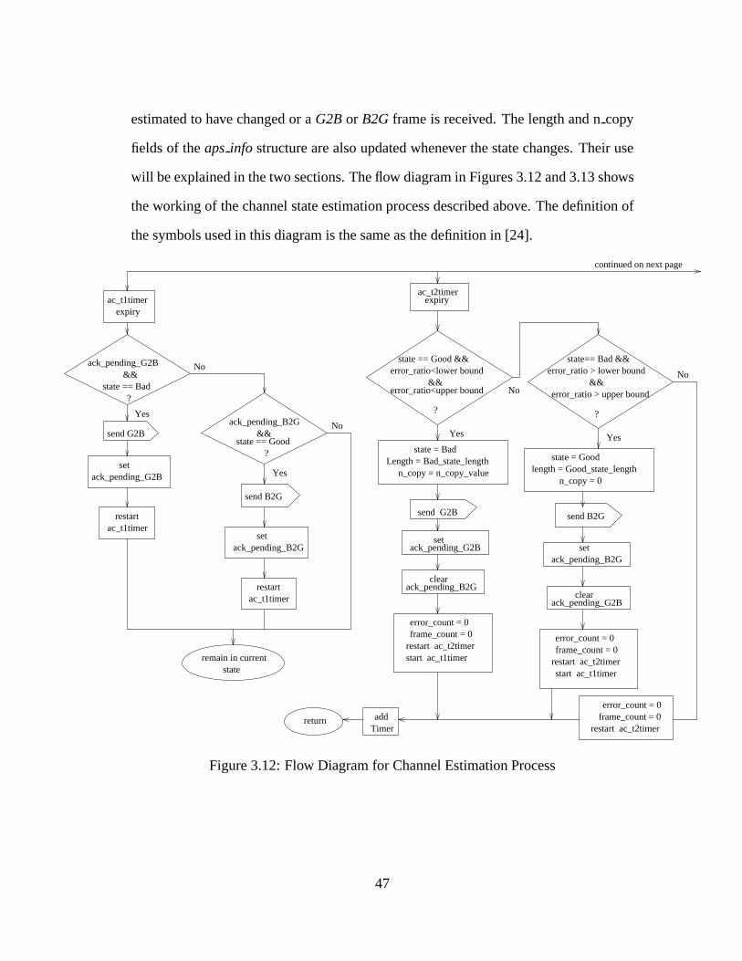
estimated to have changed or aG2Bor B2G frame is received. The length and ncopy
fields of theaps info structure are also updated whenever the state changes. Their use
will be explained in the two sections. The flow diagram in Figures 3.12 and 3.13 shows
the working of the channel state estimation process described above. The definition of
the symbols used in this diagram is the same as the definition in [24].
? state == Bad &&
ack_pending_G2B
error_ratio<upper bound &&
state == Good &&error_ratio<lower bound
expiryac_t1timer
send G2B
set ack_pending_G2B
ac_t1timerrestart
ack_pending_B2G &&
state == Good ?
send B2G
setack_pending_B2G
ac_t1timerrestart
remain in current state
expiryac_t2timer
state = BadLength = Bad_state_length
n_copy = n_copy_value
set ack_pending_G2B
clearack_pending_B2G
send G2B
error_count = 0frame_count = 0
restart ac_t2timerstart ac_t1timer
error_count = 0frame_count = 0
restart ac_t2timerstart ac_t1timer
state = Goodlength = Good_state_length
n_copy = 0
send B2G
setack_pending_B2G
clearack_pending_G2B
restart ac_t2timerframe_count = 0error_count = 0
Timeraddreturn
continued on next page
Yes
No
Yes
No
? ?
Yes
No
Yes
No
state== Bad &&error_ratio > lower bound &&error_ratio > upper bound
Figure 3.12: Flow Diagram for Channel Estimation Process
47
3.5 Adaptive Frame Length
We use the state information obtained from the channel state estimation process to adapt
the operation of the RDRN data link control protocol. The parameters that are adap-
tive in the current implementation are the wireless frame length and the retransmission
mechanism used. We will discuss the rationale behind adaptive frame lengths in this
section.
The design of the wireless frame format shown in Figure 3.4 allows for a variable
number of ATM cells to be encapsulated within each frame. Ideally encapsulating a
larger number of cells in each frame would reduce the effect of overhead due to the
frame header and trailer and increase the data throughput. However considering ran-
dom, independent bit errors in the low error rate state, the frame error rate increases as
the frame length increases for a given BER. A higher frame error rate results in lower
throughput. Thus there is an optimum frame length that produces the best throughput
under given channel conditions. Studies using loopback tests through the entire proto-
col stack (discussed in the next chapter), have indicated that a frame length of 9 cells
per frame produces the best throughput considering a BER of10�5 .
In the high-error rate state a much larger percentage of frames are going to be re-
ceived in error and will need to be retransmitted. Hence there is no advantage in having
a large frame length and it would be efficient to encapsulate as few cells as possible in
each frame when the channel is in the high-error rate state.
Hence we propose to adapt the frame length to the wireless channel state using a
frame length of 9 cells per frame in the low error state and 3 cells per frame in the
high-error rate state. The length field in theaps info structure described earlier is used
to store the current frame length and is updated whenever the estimate of the channel
state changes. Performance measurements showing the effect of this adaptive frame
48

length scheme on the throughput are discussed in the next chapter.
3.6 Pre-emptive Retransmissions
Under high-error rate conditions situations can arise when an entire window of frames
needs to be retransmitted multiple times due to errors in just one received frame. The
pre-emptive retransmission or N-Copy scheme is an attempt to reduce the number of
such occurances. The basic idea of pre-emptive retransmission is to send multiple
successive copies of each frame at each transmission and retransmission instead of just
one copy as in normal go-back-N, with the hope that at least one of these copies will be
received error-free. This will reduce the number of retransmission requests, especially
for entire windows of frames, and increase data throughput. It must be noted that the
pre-emptive retransmission scheme will be beneficial only in the high-error rate state
and that the added overhead due to multiple redundant copies of each frame in the
low error rate state would reduce the effective throughput. The ncopy field in the
aps info structure is used to store the value of the number of copies to be sent at each
transmission (ie. the value of n) and is updated whenever the estimate of the channel
state changes. We set this value to 0 in the low error rate state and to the optimal value
of n in the high error rate state. The effect of the N-Copy scheme on the throughput
performance and the optimal value ofn to be used are estimated through a series of
experiments as discussed in the next chapter.
It should be noted that we can use the pre-emptive retransmission mechanism only
for delay-insensitive traffic. This is because the sequence numbers associated with these
frames allow us to distinguish copies of frames from those being received for the first
time, which is not possible with delay-sensitive frames. We determine the advantage
of using adaptive frame lengths and of the pre-emptive retransmission mechanism both
49

separately and at the same time through a series of experiments as discussed in the next
chapter.
50

received frameerror-free
received G2B
state = Badlength = Bad_state_length
n_copy = n_copy_value
sendACK_G2B ACK_B2G
send
state = Goodlength = Good_state_length
n_copy = 0
ac_t1timer = 0set
ack_pending_G2Bclear
ac_t1timer = 0set
ack_pending_B2Gclear
ACK_G2Breceivedreceived
B2G ACK_B2Greceived
returnreturn returnreturn
frame_count ++
receivedI Frame
error_count ++
free received frame
pass receivedframe to DLC
receive functionality
?
return
Yes
No
continued fromprevious page
Figure 3.13: Flow Diagram for Channel Estimation Process (contd.)
51
Chapter 4
Performance Measurements
In this chapter we shall discuss the performance of the RDRN adaptive data link pro-
tocol measured through a series of experiments. Since we have a complete running
software implementation of the entire protocol, we study its performance through ex-
periments with the real software as opposed to a theoretical analysis or through simu-
lations.
4.1 Setup used for Performance Measurements
We have used a software loopback environment for conducting our experiments, con-
sisting of two complete adaptive protocol stacks configured as remote nodes. The loop-
back was implemented by having the transmit function at the wireless ATM interface
layer of one stack call the receive function of the corresponding layer of the other stack.
An initial prototype version of the interface card was used to generate the receive inter-
rupts whenever a wireless frame was delivered to the wireless ATM interface layer for
transmission. The stacks were built on a 120 megahertz pentium PC running version
2.0.25 of the Linux operating system together with version 0.26 of the ATM on Linux
52
distribution obtained from the LRC in Switzerland [3]. A loopback environment was
adopted as the development of all the hardware components needed for the complete
system had not been completed at the time this work was done. However all the experi-
ments detailed in the next few sections can easily be replicated on the real system once
all the development is complete. The use of the loopback allows all the software func-
tionality of both the transmit and receive components to be fully exercised independent
of the hardware.
The loopback environment consists of two complete adaptive protocol stacks and
allows use of applications running in both native-ATM mode as well as TCP/IP over
ATM mode. Our initial tests used the well knownping program to exercise the entire
transmit and receive paths in IP over ATM mode and confirm that the RDRN adaptive
protocol layers were properly integrated with the ATM on Linux distribution software.
Throughput was the metric chosen to evaluate the performance of the adaptive proto-
col. We used a variant of the well known ttcp program calledttcp atm to measure the
throughput performance under various adaptive conditions as detailed in the following
sections. Thettcp atmprogram works in native-ATM mode and was obtained as part
of the ATM on Linux distribution software.
4.1.1 Random Error Generator
As part of our test setup we also developed software to help emulate the wireless chan-
nel by randomly introducing errors in the transmit path. Errors are introduced either
by randomly dropping frames at the lowest layer of the loopback between the transmit
and receive stacks or by corrupting the AHDLC flag byte of randomly chosen wireless
frames which are detected as checksum errors at the receiver. The random error genera-
tor is very flexible and allows the error rate to be changed at predefined intervals during
53
a test thus enabling any desired error profile to be emulated. It takes in a set of frame
error rates and the time intervals at which the error rate should be changed as input.
The use of the random error generator allows us to test the working of the channel state
estimation algorithm as well as the performance of the various adaptive features of the
protocol as detailed in the following sections.
The standardttcp atmprogram mentioned earlier provides the average throughput
over the duration of a test. However in order to determine the effect of the changing
error rate and the protocol adaptations to these changes on the throughput, we need to
determine the instantaneous throughput. We have modified the ATM on Linux distri-
bution to record a count of the number of received PDU's every second, thus giving a
measure of the received throughput every second.
4.2 Optimal Frame Size for Good and Bad States
In all our experiments using the adaptive protocol we only consider the effect of ran-
dom, independent bit errors. Ifp is the bit error rate andL is the length of the wireless
frame, the frame error rateP is given by the following expression.
P = 1� (1� p)L
Thus for a given bit error rate the longer the frame length, the larger is the frame
error rate. This brings us to one of the first questions to be answered, viz., what the
optimal frame length is for various error rates. For the purposes of this study, we
assume that a channel BER of10�5 or lower means that the channel is in the good state
while a BER higher than10�5 denotes a bad state.
In our first experiment we fix the BER at10�5 and consider frame sizes from one
to ten cells per frame. Figure 4.1 shows the variation of throughput versus frame size.
As the figure shows the maximum throughput of 2 Mb/s is obtained with a frame size
54

of 9 cells per frame. As the number of cells encapsulated in each frame increases from
one cell per frame, the effect of the frame header and trailer overhead decreases and the
throughput increases. However as the frame size becomes larger the resulting frame
error rate also increases and this has an adverse impact on the throughput. Hence the
curve in Figure 4.1 has a maximum. It should be noted that our emulation of the channel
also includes a delay in the transmit path denoting the transmission time and channel
propagation delay.
1 2 3 4 5 6 7 8 9 100.2
0.4
0.6
0.8
1
1.2
1.4
1.6
1.8
2Throughput vs Wireless Frame Size (Good State)
Wireless Frame Size in ATM Cells
Thr
ough
put i
n M
bps
BER 10e−5
Figure 4.1: Variation of Throughput versus Frame Size when the Channel is in theGood State.
We also need to determine the optimal frame size in the bad state. Figure 4.2 shows
the variation of throughput versus frame size at a BER of10�4. As the figure shows
the maximum throughput is obtained with a frame size of 3 cells per frame, and has a
variation similar to that in Figure 4.1 which can be explained by a similar reasoning as
earlier. The important thing to note from Figures 4.1 and 4.2 is the large decrease in
maximum throughput at a BER of10�4 which corresponds to a frame error rate of 1 in
55

8 frames. This is due to the increase in the number of retransmissions required at the
higher BER and seems to indicate that a BER of10�5 or lower must be maintained in
our system in order to obtain reasonable performance.
1 2 3 4 5 6 7 8 90.12
0.14
0.16
0.18
0.2
0.22
0.24
0.26
0.28
0.3Throughput vs Wireless Frame Size (Bad State)
Wireless Frame Size in ATM Cells
Thr
ough
put i
n M
b/s
BER 10e−4
Figure 4.2: Variation of Throughput versus Frame Size when the Channel is in the BadState.
4.3 Effect of Adaptive Frame Lengths on Throughput
Having determined the optimal frame sizes in the good and bad states, we now evaluate
the effect of adapting the frame size to the current channel state. For the purpose of
these experiments we assume a BER of10�6 in the good state and a BER of10�4 in the
bad state. Given the results of the previous section and the knowledge that the optimal
frame size increases as the error rate decreases, we use a frame size of 10 cells per
frame in the good state and a frame size of 3 cells per frame in the bad state. In each
of the following experiments we vary the BER between10�6 and10�4 once every 12
56

seconds.
The plot in Figure 4.3 shows the variation of throughput versus time as the error
rate changes and without any channel adaptations. The throughput is measured every
second over the duration of the test. Region A and C of Figure 4.3 correspond to
the good state while region B corresponds to the bad state. We see a sharp drop in
throughput around the 12 second mark on transition to the bad state and a corresponding
sharp rise in throughput around the 24 second mark on transition back to the good state.
The average throughput in the bad state is around 0.13 Mb/s which is as expected from
Figure 4.2. However we see that the average throughput in region A and in region C
are not the same as one might expect. This appears to be due to the length of time
between timer interrupts which is 10ms in Linux. In region A, data is still being sent
down the stack by the transmit side of thettcp atm application and the send window
of the adaptive data link layer is checked for space whenever data is received from
the higher layer for transmission. If there is no space in the send window at the time
cells are received from the higher layer, they are added to thewrite queueawaiting
transmission. Thus the send window is checked for space more often than once every
10ms while in this region. In region B and C the transmit side has finished sending
all its data down the stack and cells still not transmitted are on thewrite queue. The
send queue is now checked only once in 10ms at every timer interrupt and hence the
throughput is lower in region C as compared to region A.
Having seen the variation in throughput as the channel alternates between the good
and bad states, we now evaluate the effect of the adaptive frame length mechanism
under similar conditions. As before, we vary the error rate between10�6 and10�4
every 12 seconds and measure the throughput every second. The plot in Figure 4.4
shows the variation in throughput as the error rate changes. As we can see from the
figure, the average throughput in region A and C while the channel is in the good
57

0 5 10 15 20 25 30 35 400
0.5
1
1.5
2
2.5
3
3.5Throughput without Adaptation to Channel State
Time in seconds
Thr
ough
put i
n M
bps
A
B
C
Figure 4.3: Variation of Throughput without any Adaptive Mechanisms.
state is about the same as that obtained without adaptation earlier. However the average
throughput in region B while the channel is in the bad state is around 0.32 Mb/s which is
almost three times that obtained earlier. This indicates that the channel state estimation
algorithm is able to correctly detect the change in channel state and that the concept
of adapting the frame size to the channel state is indeed beneficial. The throughput of
0.32 Mb/s obtained in the bad state is as expected from Figure 4.2. Thus the use of the
adaptive frame length mechanism produces much better throughput in the bad state and
consequently increases the average throughput over the duration of the entire test.
4.4 Effect of N Copy Mechanism on Throughput
The purpose of our next experiments are to evaluate the effect of the pre-emptive re-
transmission or NCopy mechanism on the throughput performance and to determine
58
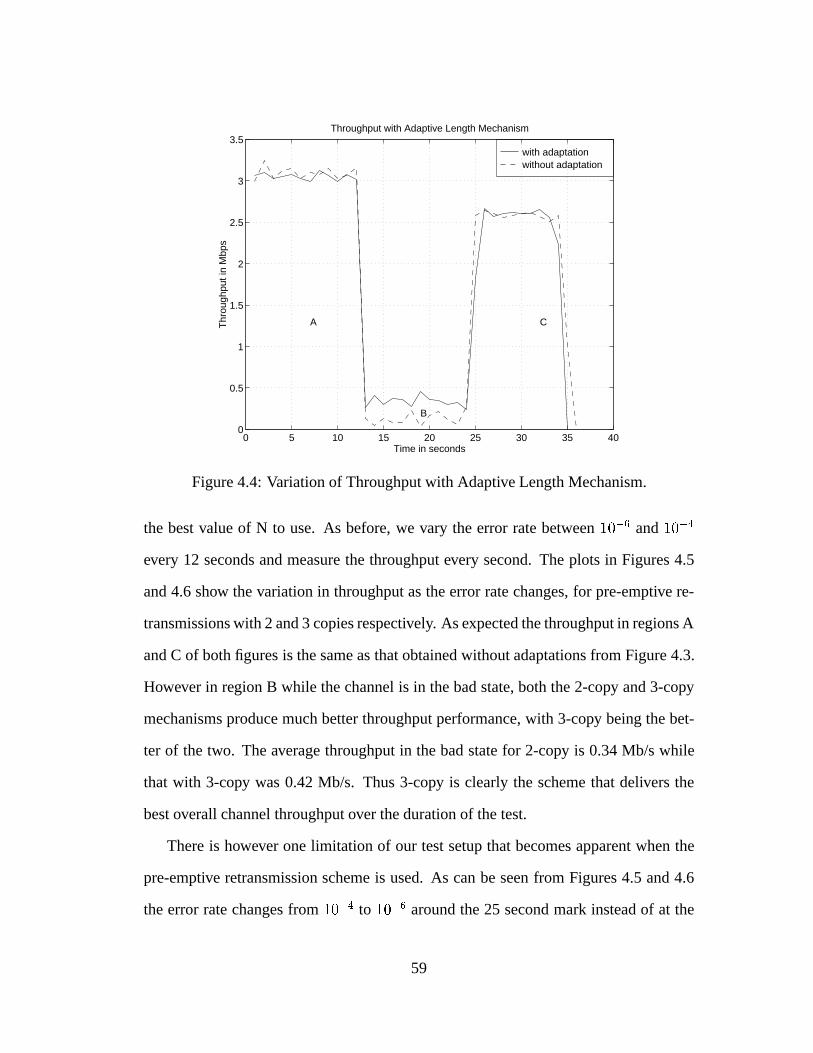
with adaptation without adaptation
0 5 10 15 20 25 30 35 400
0.5
1
1.5
2
2.5
3
3.5Throughput with Adaptive Length Mechanism
Time in seconds
Thr
ough
put i
n M
bps
A
B
C
Figure 4.4: Variation of Throughput with Adaptive Length Mechanism.
the best value of N to use. As before, we vary the error rate between10�6 and10�4
every 12 seconds and measure the throughput every second. The plots in Figures 4.5
and 4.6 show the variation in throughput as the error rate changes, for pre-emptive re-
transmissions with 2 and 3 copies respectively. As expected the throughput in regions A
and C of both figures is the same as that obtained without adaptations from Figure 4.3.
However in region B while the channel is in the bad state, both the 2-copy and 3-copy
mechanisms produce much better throughput performance, with 3-copy being the bet-
ter of the two. The average throughput in the bad state for 2-copy is 0.34 Mb/s while
that with 3-copy was 0.42 Mb/s. Thus 3-copy is clearly the scheme that delivers the
best overall channel throughput over the duration of the test.
There is however one limitation of our test setup that becomes apparent when the
pre-emptive retransmission scheme is used. As can be seen from Figures 4.5 and 4.6
the error rate changes from10�4 to 10�6 around the 25 second mark instead of at the
59

with adaptation without adaptation
0 5 10 15 20 25 30 35 400
0.5
1
1.5
2
2.5
3
3.5Throughput with 2−Copy Mechanism
Time in seconds
Thr
ough
put i
n M
bps
A
B
C
Figure 4.5: Variation of Throughput with 2-Copy Mechanism.
24 second mark as intended. This appears to be because the workload in transmitting
2 or more copies of each wireless frame for a complete window of frames is too much
to done within the 10ms between timer interrupts. Consequently the timer handler
function which does the NCopy transmission takes longer than 10ms to execute and
subsequent timer interrupts are delayed. This delay accumulates over the period that
the channel is in the bad state and transmitting Ncopies of each frame and results in
the channel remaining in the bad state for one second longer as seen in Figure 4.6. This
again is not a problem with the pre-emptive retransmission mechanism but a result of
our test setup and should disappear when a faster machine is used for tests.
60

with adaptation without adaptation
0 5 10 15 20 25 30 35 400
0.5
1
1.5
2
2.5
3
3.5Throughput with 3−Copy Mechanism
Time in seconds
Thr
ough
put i
n M
bps
A
B
C
Figure 4.6: Variation of Throughput with 3-Copy Mechanism.
4.5 Effect of the Combination of Adaptive Frame Lengths
and N Copy on Throughput
We finally determine the effect of using both the adaptive length and pre-emptive re-
transmission mechanisms when the channel is in the bad state. The plot in Figure 4.7
shows the variation in throughput as the error rate changes, with adaptive length and
pre-emptive retransmissions with 2 copies while the plot in Figure 4.7 shows a similar
variation with adaptive length and pre-emptive retransmissions with 3 copies. As we
can see from Figure 4.9, there is not much to choose between these 2 schemes by way
of performance with the average throughput in the bad state for both schemes being
about 0.36 Mb/s.
61

with adaptation without adaptation
0 5 10 15 20 25 30 35 400
0.5
1
1.5
2
2.5
3
3.5Throughput with both Adaptive Length and 2−Copy Mechanisms
Time in seconds
Thr
ough
put i
n M
bps
Figure 4.7: Variation of Throughput with Adaptive Length and 2-Copy Mechanisms.
with adaptation without adaptation
0 5 10 15 20 25 30 35 400
0.5
1
1.5
2
2.5
3
3.5Throughput with both Adaptive Length and 3−Copy Mechanisms
Time in seconds
Thr
ough
put i
n M
bps
Figure 4.8: Variation of Throughput with Adaptive Length and 3-Copy Mechanisms.
62

with adaptation 3with adaptation 2
0 5 10 15 20 25 30 35 400
0.5
1
1.5
2
2.5
3
3.5Throughput with both Adaptive Length and 3−Copy vs 2−Copy Mechanisms
Time in seconds
Thr
ough
put i
n M
bps
Figure 4.9: Variation of Throughput with Adaptive Length and 2-Copy vs AdaptiveLength and 3-Copy Mechanisms.
63

Chapter 5
Conclusions
5.1 Summary of Results and Conclusions
This thesis described the design and development of an adaptive data link layer protocol
for wireless ATM networks. The protocol handles error recovery and control over the
wireless channel and provides the ATM layer with a more reliable transport medium.
It treats delay-sensitive and delay-insensitive traffic differently thus allowing standard
ATM QOS parameters to be extended over the wireless portion of the network. Delay-
insensitive traffic received with errors is retransmitted thus resulting in zero losses at
all channel error rates.
The entire RDRN adaptive protocol stack was integrated with the standard ATM on
Linux distribution and supports applications using both TCP/IP over ATM and native-
ATM.
A simple channel state estimation algorithm was also implemented at the data link
layer level. The estimate obtained from this algorithm was used to adapt the protocol
operation to the channel state. Assuming random, independent bit errors and a BER
of 10�5, a wireless frame size of 9 cells per frame was found to produce the highest
64
throughput. A frame size of 3 cells per frame was found to be optimal considering a
BER of10�4 which was considered to denote a bad state.
Using the adaptive length mechanism, the wireless frame size was adapted to the
channel state. Experiments with this adaptive feature produced a significantly higher
throughput when the channel was in the bad state.
Using the pre-emptive retransmit or NCopy mechanism, multiple copies of each
frame were sent when the channel was in the bad state as opposed to just one copy
as with regular go-back-n. Experiments using 2 and 3 copies of each frame produced
increased throughput than without the NCopy scheme, with N=3 giving the maximum
average throughput in the bad state.
Experiments using both the adaptive length and NCopy schemes also resulted in an
increase in throughput in the bad state though the increase in average throughput was
less than that obtained with just the 3Copy scheme. Thus the adaptive mechanisms
proposed in this work all resulted in increased average throughput in the bad state with
the 3Copy mechanism producing the most increase.
It should be noted that the Ncopy scheme cannot be used for delay-sensitive traffic
in our current implementation. This is because wireless frames carrying delay-sensitive
traffic do not carry sequence numbers and hence there is no way to distinguish between
copies of frames. However the adaptive length mechanism applied to delay-sensitive
traffic was beneficial resulting in a 19% decrease in loss for a 10% decrease in through-
put.
5.2 Some Suggestions for Future Work
The implementation described in this thesis should serve as testbed for further work in
software controlled adaptive protocols. There is a lot of scope for more work especially
65
in the area of adaptive error control coding. Various FEC coding schemes can be exper-
imented with especially for use when the channel is in the good state thus transforming
the protocol to hybrid ARQ as opposed to regular go-back-N.
Another extension to consider is adding sequence numbers to wireless frames car-
rying delay-sensitive traffic. This will enable the NCopy scheme to be used for this
type of traffic also given that it has been found to deliver the best throughput when the
channel is in the bad state.
Also the simple channel state estimation algorithm proposed in this work can be
refined so that it becomes more accurate. This should eliminate some of the bogus state
changes we observed during the experiments described in chapter 4 and remove the
spikes observed in the throughput plots.
From an implementation standpoint, another area of future work is to revamp the
memory allocation strategy to reflect any new memory management schemes for Linux
when they become available with the next release of the kernel.
66

Bibliography
[1] Anthony Acampora. Wireless ATM: A Perspective on Issues and Prospects.IEEE
Personal Communications, August 1996.
[2] Prathima Agrawal, Eoin Hyden, Paul Kryzanowski, Partho Mishra, Mani B. Sri-
vastava, and John A. Trotter. SWAN: A Mobile Multimedia Wireless Network.
IEEE Personal Communications, April 1996.
[3] Werner Almesberger.Linux ATM, December 1995. Web Page URL: http://-
lrcwww.epfl.ch/linux-atm/.
[4] Werner Almesberger. Linux ATM API, July 1996. Web Page URL: http://-
lrcwww.epfl.ch/linux-atm/.
[5] Ender Ayanoglu, Kai Y. Eng, and Mark J. Karol. Wireless ATM: Limits, Chal-
lenges and Proposals.IEEE Personal Communications, August 1996.
[6] Rajive Bagrodia and Wen-Toh Liao.Maisie User Manual Release 2.1, june 1993.
[7] N. D. Birrell. Pre-emptive Retransmission for Communication over Noisy Chan-
nels. IEEE Proceedings, 128, November 1981.
67

[8] Herwig Bruneel and Marc Moeneclaey. On the Throughput Performance of Some
Continuous ARQ Strategies with Repeated Transmissions.IEEE Transactions on
Communications, COM-34(3), March 1986.
[9] Stephen F. Bush, Sunil Jagannath, Joseph B. Evans, Victor Frost, Gary Minden,
and K. Sam Shanmugan. A Control and Management Network for Wireless ATM
Systems.ACM-Baltzer Wireless Networks (WINET), 1997. To be published. Web
Page URL: http://www.tisl.ukans.edu/�sbush.
[10] Stephen F. Bush, Sunil Jagannath, Ricardo Sanchez, Joseph B. Evans, Victor
Frost, and K. Sam Shanmugan. Rapidly Deployable Radio Networks (RDRN)
Network Architecture. Technical Report 10920-09, Telecommunications & In-
formation Sciences Laboratory, July 1995. Online version available at http://-
www.tisl.ukans.edu/�sbush .
[11] L. F. Chang and J. C. I. Chuang. Outage Probability for a frequency-selective
fading digital portable radio channel with selection diversity using coding. In
IEEE International Conference on Communications, 1990.
[12] K. Y. Eng, M. J. Karol, M. Veeraraghavan, E. Ayanoglu, C. B. Woodworth, P. Pan-
cha, and R. A. Valenzuela. BAHAMA: A Broadband Ad-Hoc Wireless ATM
Local-Area Network. InProceedings of ICC'95, February 1995.
[13] Benjamin Ewy, Craig Sparks, and K. Sam Shanmugan. An Overview of the
Rapidly Deployable Radio Network Proof of Concept System. Technical Report
10920-16, Telecommunications & Information Sciences Laboratory, July 1995.
[14] D. D. Falconer. A System Architecture for Broadband Millimeter-wave Access to
an ATM LAN. IEEE Personal Communications, August 1996.
68
[15] Shane Haas. A Consistent Labeling Algorithm for the Frequency/Code Assign-
ment in a Rapidly Deployable Radio Netw ork (RDRN). Technical Report TISL-
10920-04, Telecommunications & Information Sciences Laboratory, Jan 1995.
[16] IEEE. AX.25 Amateur Packet Radio Link-Layer Protocol, October 1984.
[17] B M Leiner, D L Neilson, and F A Tobagi. Issues in Packet Radio Network
Design.Proceedings of the IEEE, January 1987.
[18] H. W. H. Li and J. K. Cavers. An Adaptive Filtering Technique for pilot-aided
transmission systems.IEEE Transactions on Vehicular Technology, 40, 1991.
[19] J. Porter, A. Hopper, D. Gilmurray, O. Mason, J. Naylon, and A. Jones. The ORL
Radio ATM System, Architecture and Implementation. Technical report, Olivetti
Research Ltd. and University of Cambridge Computer Laboratory, January 1996.
Available at ftp://ftp.orl.co.uk/pub/docs/ORL/paper.96.2.ps.Z.
[20] John Porter and Andy Hopper. An ATM-Based Protocol for Wireless LANs. Tech-
nical Report Tech. Rep. 94.2, Olivetti Research Ltd., April 1994. Available at
ftp://ftp.cam-orl.co.uk/pub/docs/ORL/tr.94.2.ps.Z.
[21] Dipankar Raychaudhuri. WirelessATM Networks: Architecture, System Design
and Prototyping.IEEE Personal Communications, August 1996.
[22] Dipankar Raychaudhuri and Newman D. Wilson. ATM-Based Transport Archi-
tecture for Multi-services Wireless Personal Communication Networks.IEEE
Journal of Selected Areas in Communication, June 1994.
[23] A. R. K. Sastry. Improving Automatic Repeat-Request (ARQ) Performance on
Satellite Channels Under High Error Rate Conditions.IEEE Transactions on
Communications, April 1975.
69
[24] Eric L. Scace. Introducing System Description Language for AX.25 and Related
Protocols. InProceedings of the 7th AARL Amateur Radio Computer Networking
Conference, October 1988.
[25] Daniel J. Costello Jr. Shu Lin and Micheal J. Miller. Automatic-Repeat-Request
Error-Control Schemes.IEEE Communications Magazine, 22(12), December
1984.
[26] H. Xie, P. Narasimhan, R. Yuan, and D. Raychaudhuri. Data Link Control Proto-
cols for Wireless ATM Access Channels. InInternational Conference on Univer-
sal Personal Communications (ICUPC), Nov 1995.
[27] Yu-Dong Yao. An Effective Go-Back-N ARQ Scheme for Variable-Error-Rate
Channels.IEEE Transactions on Communications, 43(1), January 1995.
[28] Michele Zorzi and Ramesh R. Rao. Performance of ARQ Go-Back-N protocol
in Markov Channels with Unreliable Feedback: Delay Analysis. InInternational
Conference on Universal Personal Communications (ICUPC), Nov 1995.
70