an adaptive noise cancelling system to enhance sonar ... · tms320c31 dsp abstract the performance...
TRANSCRIPT
Disclaimer: This document was part of the FirstEuropean DSP Education and Research Conference.It may have been written by someone whose nativelanguage is not English. TI assumes no liability for thequality of writing and/or the accuracy of theinformation contained herein.
Implementing an Adaptive NoiseCancelling System to Enhance SonarReceiver Performance Using theTMS320C31 DSP
Authors: E. Verriest, Isen
ESIEE, ParisSeptember 1996SPRA337

IMPORTANT NOTICE
Texas Instruments (TI) reserves the right to make changes to its products or to discontinue anysemiconductor product or service without notice, and advises its customers to obtain the latest version ofrelevant information to verify, before placing orders, that the information being relied on is current.
TI warrants performance of its semiconductor products and related software to the specifications applicableat the time of sale in accordance with TI’s standard warranty. Testing and other quality control techniquesare utilized to the extent TI deems necessary to support this warranty. Specific testing of all parameters ofeach device is not necessarily performed, except those mandated by government requirements.
Certain application using semiconductor products may involve potential risks of death, personal injury, orsevere property or environmental damage (“Critical Applications”).
TI SEMICONDUCTOR PRODUCTS ARE NOT DESIGNED, INTENDED, AUTHORIZED, OR WARRANTEDTO BE SUITABLE FOR USE IN LIFE-SUPPORT APPLICATIONS, DEVICES OR SYSTEMS OR OTHERCRITICAL APPLICATIONS.
Inclusion of TI products in such applications is understood to be fully at the risk of the customer. Use of TIproducts in such applications requires the written approval of an appropriate TI officer. Questions concerningpotential risk applications should be directed to TI through a local SC sales office.
In order to minimize risks associated with the customer’s applications, adequate design and operatingsafeguards should be provided by the customer to minimize inherent or procedural hazards.
TI assumes no liability for applications assistance, customer product design, software performance, orinfringement of patents or services described herein. Nor does TI warrant or represent that any license,either express or implied, is granted under any patent right, copyright, mask work right, or other intellectualproperty right of TI covering or relating to any combination, machine, or process in which suchsemiconductor products or services might be or are used.
Copyright © 1997, Texas Instruments Incorporated

TRADEMARKS
TI is a trademark of Texas Instruments Incorporated.
Other brands and names are the property of their respective owners.

CONTACT INFORMATION
US TMS320 HOTLINE (281) 274-2320
US TMS320 FAX (281) 274-2324
US TMS320 BBS (281) 274-2323
US TMS320 email [email protected]

ContentsAbstract ........................................................................................................................... 7Product Support on the World Wide Web .................................................................... 8Introduction..................................................................................................................... 9
Adaptive Noise Cancelling.......................................................................................... 9Algorithm Selection................................................................................................... 12
The LMS Algorithm........................................................................................... 12The "Spectrofiltre" Algorithm. ........................................................................... 13
DSP Implementation................................................................................................. 14Real Time Validation................................................................................................. 14
Conclusion .................................................................................................................... 21References .................................................................................................................... 22

FiguresFigure 1. The Adaptive Noise Cancelling Concept............................................................... 9Figure 2. Program Execution Flow Diagram ...................................................................... 15Figure 3. Power Spectrum of Hydrophone Output ............................................................. 16Figure 4. Coherence Between Primary/Reference Input.................................................... 17Figure 5. Results of ANC on the Primary Input Power Spectrum (Method of
Spectrofiltre)........................................................................................................ 18Figure 6. Coherence Between Primary Input and Reference Input After/Before Noise
Cancellation ........................................................................................................ 19Figure 7. Cancellation of Frequency Components of the Input Signal ............................... 20
Implementing an Adaptive Noise Cancelling System to Enhance Sonar Receiver 7Performance Using the TMS320C31 DSP
Implementing an Adaptive NoiseCancelling System to Enhance Sonar
Receiver Performance Using theTMS320C31 DSP
Abstract
The performance of sonar receivers on board a ship are degradedby mechanical noise. In order to improve the detectionperformance of the acoustic sensors (hydrophones), we havedesigned a local mechanical noise cancelling system using theAdaptive Noise Cancelling (ANC) approach with a single noisereference [1]. The implementation was realized and validated onunderwater acoustic signals with a PC-based Texas Instruments(TI™) TMS320C31 floating-point digital signal processor (DSP)system.
This document was part of the first European DSP Education andResearch Conference that took place September 26 and 27, 1996in Paris. For information on how TI encourages students fromaround the world to find innovative ways to use DSPs, see TI’sWorld Wide Web site at www.ti.com.

SPRA337
8 Implementing an Adaptive Noise Cancelling System to Enhance Sonar ReceiverPerformance Using the TMS320C31 DSP
Product Support on the World Wide Web
Our World Wide Web site at www.ti.com contains the most up todate product information, revisions, and additions. Usersregistering with TI&ME can build custom information pages andreceive new product updates automatically via email.

SPRA337
Implementing Adaptive Noise Cancelling to Enhance Sonar Receiver Performance 9
Introduction
In our work, we consider different adaptive methods of filteridentification [2] in order to estimate the signal from a noisyhydrophone output. In a first approach, we have carried outsimulations to calculate the performance of each ANC method andhave demonstrated the advantage of frequential methods formechanical noise cancellation. Taking the numerical stability, rateof convergence and simplicity as selection criteria, we haveselected the LMS (Least Mean Square, time method) and the"Spectrofiltre" (frequential method) for our application.
Adaptive Noise Cancelling
We assume in this paper that we are processing real, discrete-time, statistically stationary signals with zero mean. Noisecancellation can be viewed as a problem of adaptive filteridentification
Figure 1. The Adaptive Noise Cancelling Concept

SPRA337
10 Implementing an Adaptive Noise Cancelling System to Enhance Sonar ReceiverPerformance Using the TMS320C31 DSP
A signal s is transmitted over a channel to a sensor that alsoreceives a noise b uncorrelated with the signal. The combinedsignal and noise s+b form the primary input y to the canceller. Asecond sensor receives a noise r uncorrelated with the signal butcorrelated in some unknown way with the noise b. We can alsofind a filter W generating b from r. The classical ANC methodsestimate this filter in the class of linear filters. Two approaches arepossible: a time and a frequential approach. In order to estimatethe filter W, a FIR transversal filter structure is chosen because itleads to a real-time adaptive implementation of the signals [3]. Inthe time domain, the adaptive filter is defined by its N tap weights.In the frequency domain, it is defined by the N weights of itscomplex gain. The estimation criterion is the minimization of thesystem output power E[Ie(k)I2] (in an ANC system, the systemoutput serves as the error signal for the adaptive process [1].Besides, this criterion leads to simple calculations [2] andminimizing the system output power minimizes the Mean-SquaredError (MSE) E[Ie(k)-s(k)l2] and maximizes the output signal-to-noise ratio under the fundamental assumption that the referenceinput is not correlated with the signal. 4
The optimal solution in the time domain for a N tap weightstransversal filter is given by the discrete Wiener-Hopf equation [5]:
yrrNopt pF •Γ=−1
][ ][ (1)
where Γr is the (N,N) correlation matrix of the reference input, and
yrp is the (N, 1) cross-correlation vector between the tap-
reference input and the primary input. In the frequency domain,the optimal solution is given by:
))(/())(()( vvvF rryropt γγ= (2)
where γyr (V) is the Fourier transform of the intercorrelation functionbetween the primary input and the reference input, and γrr ( ) isthe Fourier transform of the reference input autocorrelationfunction. These solutions require a priori knowledge about thesecond order input signal statistics. Since we do not have thisinformation, we use deterministic estimation criteria instead ofstatistic ones.
In the time domain, we use the following estimation criterion
2
0
)()( jekCk
j
jk
•= ∑=
−λ (3)

SPRA337
Implementing Adaptive Noise Cancelling to Enhance Sonar Receiver Performance 11
where λ is an exponential weighting factor. We have chosen anexponential window because the signals we have to process arequasi stationary. Besides, this leads to reductions in thecomputation of the noise-cancelling algorithms [6]. We obtain thecorresponding deterministic solution by differentiating C(k) withrespect to the N-tap weights transversal filter [2]:
)(ˆ)](ˆ[ˆ1
][ kpkFyrr
k
Nopt •Γ=−
(4)
where:
][][0
)(ˆ NjT
Nj
k
j
jk
r rrk ••=Γ ∑=
−λ (5)
][)()(ˆ Nj
k jk
yrrjykp ••= ∑
−λ (6)
In the frequency domain, (2) requires the estimation of the powerspectra of the observed signals. We use the averagedperiodogram method to estimate the power spectra with anexponential weighting factor in order to take into account possibleslow variations of the input signals statistics
)()()(ˆ1
vrvyv jj
L
j
jLL
yr ••= ∑=
−λγ (7)
)()()(ˆ1
vrvrv jj
L
j
jLL
rr ••= ∑=
−λγ (8)
where rj(v) is the conjugate of the N-sample j-th section DFT ofthe signal r(k) and L is the number of input sections.
To conclude, the optimal Wiener filter is the solution of theminimization of a statistic quadratic criterion. The deterministicapproach is necessary because we have no a priori informationabout the second order statistics of the input signals. However,both approaches are equivalent for ergodic signals [2] The timeand the frequency approach lead to equivalent solutions for aninfinite order of the transversal filter [2].

SPRA337
12 Implementing an Adaptive Noise Cancelling System to Enhance Sonar ReceiverPerformance Using the TMS320C31 DSP
Algorithm Selection
In a first approach, we have carried out simulations on severalwide-band noises and single tones to calculate the performancesof each ANC method and prove the advantage of frequentialmethods in the processing of mechanical noise. Taking numericalstability, convergence rate and simplicity as selection criteria forthe algorithms, we have selected the LMS (Least Mean Square), asuboptimal time method, and the "Spectrofiltre", an optimalfrequential method.
The LMS Algorithm.
The MSE can be developed to a second-order function of theestimation filter [5]. Accordingly, we may visualize the dependenceof the MSE on the filter weights as a bowl-shaped surface with aunique minimum. We refer to this surface as the error-performance surface of the transversal filter. The requirement is todesign the filter so that it operates at the bottom of this surface. Atthis point, the MSE attains its minimum value, andcorrespondingly, the adaptive filter attains its optimum value in themean-squared sense. The LMS algorithm does not requiremeasurement of the correlation functions, nor does it requirematrix inversion. It uses the method of steepest descent on theerror-performance surface by approximating the gradient vector inreal time with available data.
Summary of the LMS Algorithm.
Parameters: N = filter order;µ = step-size parameter.
Definition : rk[N] = [r(k) r(k-1)... r(k-N+1)]T
Initialization : = r0[N]=0 ; F0[N]=0
Computation (k=1,…)
][1][ ]([)()( Nk
kN rFkyke •−= − (9)
][1][][ )( Nk
kN
kN rkeFF ••+= − µ (10)

SPRA337
Implementing Adaptive Noise Cancelling to Enhance Sonar Receiver Performance 13
The "Spectrofiltre" Algorithm.
The power spectra of the observed signals are estimated with theaveraged periodogram method [8]; the "Overlap-Save-Method"(OSM) is used in order to avoid the effects of circular convolution[7].
Parameters : N = filter order;D = overlapping points;λ = weighting factor.
Initialization : the (N/2+1) complex weights of the adaptive filterand estimated interspectrum are zero; the (N/2+1) real weights ofthe estimated autospectrum are zero.
Input signals are sectioned according to the OSM method ; thecurrent N-point sections are denoted as yj(k) and rj(k).
Computation (j = 1, …):
yj(k) and rjk) are transformed by FFT ; we obtain N/ 2+1 complexpoints yj(v) and rj(v).
)()()()(1
vrvFvyve j
j
jj
−−= (11)
ej(v) is inverse transformed by IFFT; the first D points are thendiscarded (OSM). We estimate the interspectrum between theprimary and reference input:
)()()(ˆ)(ˆ1
vrvyvyv jj
j
yr
j
yr •+•=−
λγ (12)
We estimate the power spectrum density of the reference input:
)()()(ˆ)(ˆ1
vrvrvv jj
j
rr
j
rr •+•=−
γλγ (13)
Finally, the complex gain of the adaptive filter is calculated:
))(ˆ/())(ˆ()( vvvFj
rr
j
yr
j
γγ= (14)
SPRA337
14 Implementing an Adaptive Noise Cancelling System to Enhance Sonar ReceiverPerformance Using the TMS320C31 DSP
DSP Implementation
We have implemented the LMS and the Spectrofiltre algorithmson a Texas Instruments 32 bit floating-point DSP: theTMS320C31. Excellent real-time results have been attained, wellabove the minimum required for a signal band of 1-6 KHz(underwater acoustic signals). Hand-written assembler code wasnecessary in order to optimize the real-time performance of thealgorithms. We shall now give some details about theimplementation of the OSM for the Spectrofiltre algorithm. Weknow that the filtering operation, when carried out in the frequencydomain, may produce estimation errors because a multiplication ofDFTs corresponds to the circular convolution of the timesequences [8]. The OSM is equivalent to implementing a circularconvolution and identifying the part that corresponds to a linearconvolution. For example, if we consider the circular convolutionof the M-point unit-sample response with an N-point section, thefirst (M-1) points are incorrect while the remaining points areidentical to those that would be obtained had we implemented alinear convolution. We also section the input signals y(k), r(k) intosections of length N so that each section overlaps the precedingone by D points. Each section is FFT’d and processed, but wediscard the first D points of each output section since this portionis corrupted by the effects of circular convolution. The (N-D)remaining points from successive sections are then abutted toconstruct the final filtered output. Each succeeding input sectionconsists of (N-D) new points and D points saved from the previoussection. In our application, unfiltered signals are input to the 16 bitparallel A/D converter via an Interrupt Service Routine which fillstwo circular input buffers with fresh data y(k) and r(k). The ISRalso outputs the estimated signal (Figure 2).
While the main program processes the current section of Nsamples (section j), the ISR inputs new data from the section (j+1)and simultaneously outputs the estimated signal corresponding tothe section (j-1).
Real Time Validation
The real-time validation of the algorithms was subsequentlyrealized on underwater acoustic signals. The experiment used athin steel plate positioned at the air-water interface carrying anaccelerometer on the air side and the hydrophone directly below iton the water side. The signal to be detected was generated by asubmerged transducer and the noise by a vibration exciter on theplate. The sensor signals were processed by our PC-based TITMS320C31 floating-point DSP system.

SPRA337
Implementing Adaptive Noise Cancelling to Enhance Sonar Receiver Performance 15
Figure 2. Program Execution Flow Diagram
We have attained excellent real-time results for the subtraction ofnoise spectral components and reduction of coherence betweenthe sensor signals, especially with the Spectrofiltre algorithm. Theparallel operations instructions group makes a high degree ofparallelism possible and allowed a sampling frequency of 32 KHzfor this algorithm. The computational requirements for theSpectrofiltre with N=1024 are about 115000 machine cycles forthe processing of a 1024 section. We can also use an overlappingrate of 90% with a sampling frequency of 16KHz.
Assembly language programming for the LMS algorithm hasproduced a computational complexity of 3N+100 machine cyclesfor the processing of a couple of samples y(k), r(k). This allows usto use a 360 tap-weight adaptive transversal filter with a samplingfrequency of 16 KHz.
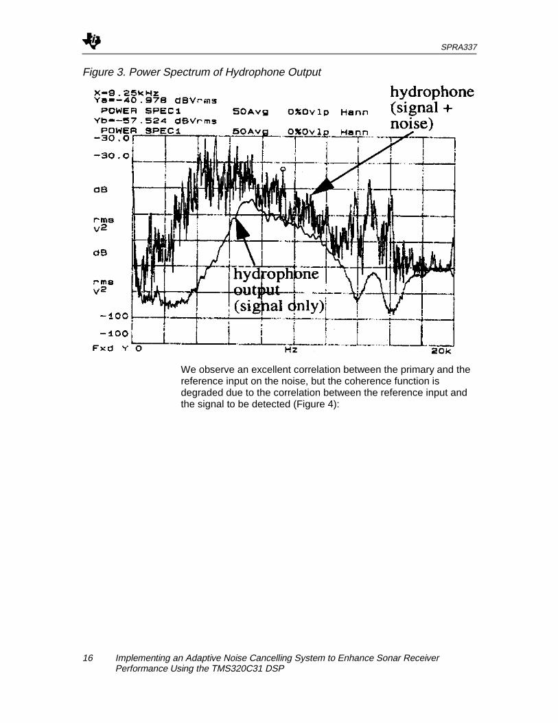
The submerged hydrophone measures an additive noisecorresponding to the plate vibrations ; the power spectrum of thehydrophone output with and without the noise is shown in Figure3.
SPRA337
16 Implementing an Adaptive Noise Cancelling System to Enhance Sonar ReceiverPerformance Using the TMS320C31 DSP
Figure 3. Power Spectrum of Hydrophone Output
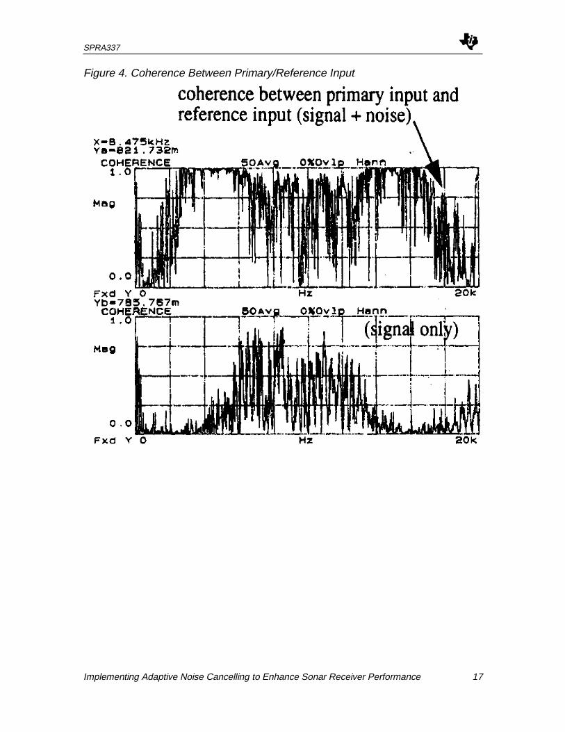
We observe an excellent correlation between the primary and thereference input on the noise, but the coherence function isdegraded due to the correlation between the reference input andthe signal to be detected (Figure 4):
SPRA337
Implementing Adaptive Noise Cancelling to Enhance Sonar Receiver Performance 17
Figure 4. Coherence Between Primary/Reference Input

SPRA337
18 Implementing an Adaptive Noise Cancelling System to Enhance Sonar ReceiverPerformance Using the TMS320C31 DSP
Figure 5. Results of ANC on the Primary Input Power Spectrum (Method ofSpectrofiltre)
The Spectrofiltre achieves excellent cancellation of the noisespectral components (N=1024, D=512) (see Figure 5).
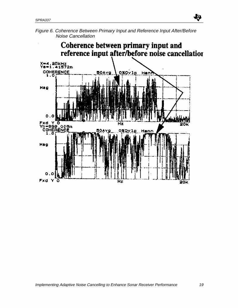
Further, we have a coherence reduction between the referenceinput and the estimated signal, which corresponds to an effectivecancellation of the noise spectral components [2] (see Figure 6).However, the correlation between the reference input and thesignal to be detected induces some distortion of the signal afternoise cancellation (Figure 7). We have also shown that it isabsolutely necessary for the reference input to be decor-relatedwith the signal to detect, if we want to obtain good noisecancelling performance. The LMS algorithm has not reached theperformance of the Spectrofiltre method, which confirms theadvantage of frequential ANC methods over time ANC methods.
SPRA337
Implementing Adaptive Noise Cancelling to Enhance Sonar Receiver Performance 19
Figure 6. Coherence Between Primary Input and Reference Input After/BeforeNoise Cancellation

SPRA337
20 Implementing an Adaptive Noise Cancelling System to Enhance Sonar ReceiverPerformance Using the TMS320C31 DSP
Figure 7. Cancellation of Frequency Components of the Input Signal

SPRA337
Implementing Adaptive Noise Cancelling to Enhance Sonar Receiver Performance 21
Conclusion
To our knowledge, no real-time validation of frequential ANCmethods has yet been done. The Spectrofiltre method has provedefficient in floating-point implementation for the reduction ofmechanical noise on a sonar receiver. A real-time implementationand validation of the fast RLS algorithms is being conducted.

SPRA337
22 Implementing an Adaptive Noise Cancelling System to Enhance Sonar ReceiverPerformance Using the TMS320C31 DSP
References
[1] B. Widrow et al., "Adaptive noise cancelling : principles andapplications”, Proc. Of the IEEE, 1975
[2] C. Servière, "Eléments de comparaison entre différentes méthodesde Soustraction de Bruit”, Thèse de Doctorat, 1989
[3] F. Michaut, "Méthodes adaptatives pour le signal", 1992
[4] J.F. Guerre-Chaley, "Etude de différentes structures de soustracteursde bruit adaptatifs multiréférences", Thèse de Doctorat,1990
[5] S. Haykin, "Adaptive Filter theory", 1986
[6] J. Cioffi, T. Kailath, “Windowed Fast Transversal Filters AdaptiveAlgorithms with Normalization”, IEEE Trans. On ASSP,1985
[7] C. Servière, “Comparison between two estimation methods of thecomplex gain of an optimal Wiener filter”, Traitement duSignal, 1989
[8] A. V. Oppenheim, R. W. Schafer, “Digital Signal Processing”, 1975