an advance repetitive control scheme for fuzzy …fig. 1 shows the block diagram of proposed control...
TRANSCRIPT
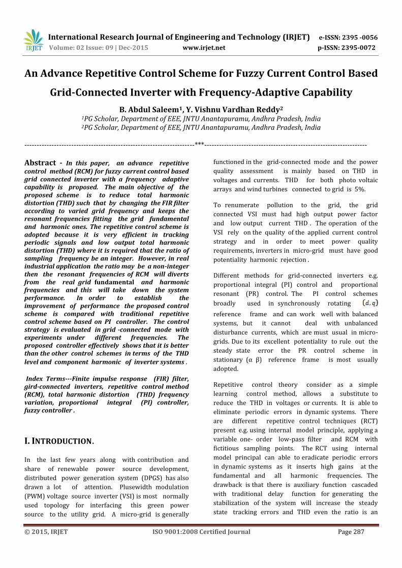
International Research Journal of Engineering and Technology (IRJET) e-ISSN: 2395 -0056
Volume: 02 Issue: 09 | Dec-2015 www.irjet.net p-ISSN: 2395-0072
© 2015, IRJET ISO 9001:2008 Certified Journal Page 287
An Advance Repetitive Control Scheme for Fuzzy Current Control Based
Grid-Connected Inverter with Frequency-Adaptive Capability
B. Abdul Saleem1, Y. Vishnu Vardhan Reddy2 1PG Scholar, Department of EEE, JNTU Anantapuramu, Andhra Pradesh, India 2PG Scholar, Department of EEE, JNTU Anantapuramu, Andhra Pradesh, India
---------------------------------------------------------------------***------------------------------------------------------------------
Abstract - In this paper, an advance repetitive control method (RCM) for fuzzy current control based grid connected inverter with a frequency adaptive capability is proposed. The main objective of the proposed scheme is to reduce total harmonic distortion (THD) such that by changing the FIR filter according to varied grid frequency and keeps the resonant frequencies fitting the grid fundamental and harmonic ones. The repetitive control scheme is adopted because it is very efficient in tracking periodic signals and low output total harmonic distortion (THD) where it is required that the ratio of sampling frequency be an integer. However, in real industrial application the ratio may be a non-integer then the resonant frequencies of RCM will diverts from the real grid fundamental and harmonic frequencies and this will take down the system performance. In order to establish the improvement of performance the proposed control scheme is compared with traditional repetitive control scheme based on PI controller. The control strategy is evaluated in grid -connected mode with experiments under different frequencies. The proposed controller effectively shows that it is better than the other control schemes in terms of the THD
level and component harmonic of inverter systems .
Index Terms---Finite impulse response (FIR) filter, gird-connected inverters, repetitive control method (RCM), total harmonic distortion (THD) frequency variation, proportional integral (PI) controller, fuzzy controller .
I. INTRODUCTION.
In the last few years along with contribution and
share of renewable power source development,
distributed power generation system (DPGS) has also
drawn a lot of attention. Plusewidth modulation
(PWM) voltage source inverter (VSI) is most normally
used topology for interfacing this green power
source to the utility grid. A micro-grid is generally
functioned in the grid-connected mode and the power
quality assessment is mainly based on THD in
voltages and currents. THD for both photo voltaic
arrays and wind turbines connected to grid is 5%.
To renumerate pollution to the grid, the grid
connected VSI must had high output power factor
and low output current THD . The operation of the
VSI rely on the quality of the applied current control
strategy and in order to meet power quality
requirements, inverters in micro-grid must have good
potentiality harmonic rejection .
Different methods for grid-connected inverters e.g.
proportional integral (PI) control and proportional
resonant (PR) control. The PI control schemes
broadly used in synchronously rotating
reference frame and can work well with balanced
systems, but it cannot deal with unbalanced
disturbance currents, which are must usual in micro-
grids. Due to its excellent potentiality to rule out the
steady state error the PR control scheme in
stationary (α β) reference frame is most usually
adopted.
Repetitive control theory consider as a simple
learning control method, allows a substitute to
reduce the THD in voltages or currents. It is able to
eliminate periodic errors in dynamic systems. There
are different repetitive control techniques (RCT)
present e.g. using internal model principle, applying a
variable one- order low-pass filter and RCM with
fictitious sampling points. The RCT using internal
model principal can able to eradicate periodic errors
in dynamic systems as it inserts high gains at the
fundamental and all harmonic frequencies. The
drawback is that there is auxiliary function cascaded
with traditional delay function for generating the
stabilization of the system will increase the steady
state tracking errors and THD even the ratio is an

International Research Journal of Engineering and Technology (IRJET) e-ISSN: 2395 -0056
Volume: 02 Issue: 09 | Dec-2015 www.irjet.net p-ISSN: 2395-0072
© 2015, IRJET ISO 9001:2008 Certified Journal Page 288
Fig-1: Block diagram of a three-phase grid-connected inverter with the improved repetitive control scheme integer. The RCM using a Variable one-order low-pass
filter can easily follows varied grid frequency but the
limitation is that the resonant points and the
fundamental frequency of the grid can be perfectly
fits and the rest of the resonant points still deviate
from the harmonic compensation performance. The
RCM with fictitious sampling points can keep the
ratio of sampling frequency to the grid frequency be an
integer. But, fictitious sampling points are derives
from the actual sampling points by linear calculation,
and there are errors between them.
In this paper an advance RCM for Fuzzy current control
based grid-connected inverter is proposed. This
scheme innovates a special designed FIR filter which
is cascaded along with a traditional delay function.
The FIR filter substitutes the auxiliary function can
estimate the ideal repetitive control function of any
ratio. The advance scheme modifies the FIR filter
according to the varied fundamental and harmonic
frequencies. Thus, minimize the THD and tracking
error.
This paper is organized as follows Section II briefly
introduces the description of the system. Fuzzy
current control based grid- connected VSI is analyzed
in section III along with RCS is examined. In section
IV, the simulation as well as experimental results, the
comparison is also provided to demonstrate the
improvement of performance of the proposed scheme
over the existing schemes. The conclusions from the
research are summarized in section V.
II. DESCRIPTION OF THE SYSTEM
Fig. 1 shows the block diagram of proposed control scheme i.e., an advance RCM for fuzzy current control based grid-connected inverters with frequency adaptive capability which consists of grid, insulated gate bipolar transistor (IGBT) inverter bridge, an LCL filter, PWM voltage source inverter(VSI), fuzzy based current controller, phase–locked loop (PLL),
and converters. Where and are filter
inductors and filter capacitors respectively, is grid
interface inductor; proportional regulator and ;
is voltage across DC supply ; , and
, , grid currents and grid voltages respectively,

International Research Journal of Engineering and Technology (IRJET) e-ISSN: 2395 -0056
Volume: 02 Issue: 09 | Dec-2015 www.irjet.net p-ISSN: 2395-0072
© 2015, IRJET ISO 9001:2008 Certified Journal Page 289
which are transformed into , and , . A phase-
locked loop (PLL) is uses to provide the phase
information ‘θ’ of the grid voltages for
transformation and the ratio ‘N’ of the sampling frequency to grid frequency for the current
controller. The circuit breaker S is needed during the synchronization and shutdown procedure. The circuit breakers could be closed at any time if the generated voltages should be equal to the grid voltages. In order to achieve this, the and are feed forwarded
and injected to the output of the current controller via a proportional regulator ; and via are
also added to the output of the current controller to decouple each other [24]. The inverter is assumed to be powered by a constant dc voltage source.
III. DESIGN OF THE IMPROVED REPETITIVE
CURRENT CONTROLLER
The block diagram of the improved repetitive control is shown in Fig. 2. The current controller is accomplished based on the fuzzy controller and RCT after establishing the inverter model. The main objective of the fuzzy current controller is to infuse a clean and balanced current to the grid. (s) is the transfer
function of the VSI in the synchronous reference frame (SRF). (s) is the transfer function of the fuzzy
control for fundamental current regulation; Q(s),
and (s) are the three factors. (s) is the
current-decoupling factor, and (s) is the grid
voltage feedforward factors (s) is the VSI output
current inserted into the grid, (s) is reference
current and (s) is the disturbance of the grid
current. When the inverter develops the power, the repetitive current controller makes appropriate contributions on the top of the feed forwarded grid voltages. The output current to the grid is used as feedback and the micro-grid voltage is maintained using the feed forwarded grid voltage .
A. Model of the Three-Phase Grid-Connected
VSI in the SRF
Fig.1 shows a system having two stages i.e.,
power stage and control scheme. The power stage is a
system topology of three-phase grid-connected
insulated gate bipolar transistor and has a LCL filter
connected the inverter output with the grid which
converters a dc input voltage into an ac sinusoidal
Fig-2: Block diagram of the improved repetitive control
scheme.
voltage by means of appropriate switch signals to
make the output current in phase with the utility
voltage. Thus the current and and voltage of
capacitor are chosen as state variables ; then the
model is given as

International Research Journal of Engineering and Technology (IRJET) e-ISSN: 2395 -0056
Volume: 02 Issue: 09 | Dec-2015 www.irjet.net p-ISSN: 2395-0072
© 2015, IRJET ISO 9001:2008 Certified Journal Page 290
Here is the parasitic resistance of filter inductor,
is the parasitic resistance of filter capacitor and is
the parasitic resistance of grid interface inductor and
and where equals to minus , equals to
minus etc., , and the control signals.
The transformation matrix from the stationary
reference frame to synchronous reference frame is
Where =2 , = grid fundamental frequency. Thus,
multiply the equations (1)—(3) with on both sides,
then
(5)
Where
In reality system are physically non – ideal; a completely
accurate model could not be established. Therefore in
this paper, the coupling capacitor voltage is neglected ,
which means the matrix X in (7) is zero. (s), the
transfer function of the voltage source invertor in the
SRF present in equation (5A), shown at the bottom of the
page, is directly derived from (5)—(7) by taking the
laplace transform of equation(5)—(7) and neglecting
the term whose coefficient is . Moreover co-
efficient of the current is
B. Repetitive Controller Design
The block diagram of the improved repetitive control
scheme is shown in Fig.2 the tracking error of the voltage
source invertor without repetitive controller is
The RCS proposed in this paper is a plug-in type
(s) is the current-decoupling factor and
(s) is the grid voltage feedforward factor. (s)
is the VSI output current inserted into the grid, (s)
is its reference, and (s) is the disturbance of the grid
current. The tracking error of the VSI with repetitive
controller in Fig.2. Equation (10) can be modified as

International Research Journal of Engineering and Technology (IRJET) e-ISSN: 2395 -0056
Volume: 02 Issue: 09 | Dec-2015 www.irjet.net p-ISSN: 2395-0072
© 2015, IRJET ISO 9001:2008 Certified Journal Page 291
Here H(s) = (s) / ( )
The closed system in Fig.2, is stable if it satisfy the
following condition
By using the Taylor progression, the equation (11) can
be expressed as
(12)
(13)
The equation (13) indicates that repetitive controller
does not take effect on the first cycle if
From the second cycle onward, the error can be
simplified to if equation
(14) is possible When
Because of the tolerance of the devices equation (14)
and (15) cannot be ideally satisfied. At fundamental and
all harmonic frequencies the tracking error in
equation(11) can be zero. Q(s) is elected as a low order
low pass filter, then
is elected as
Here p is pole for robustness Then the stability
condition of equation (12) would be satisfied too and
the harmonic elimination requirements of equation (14)
and equation (15) also almost quenched.
Fig-3: Block diagram of the repetitive control technique. (a) Time domain. (b) Discrete-time domain.
C. Improved Repetitive Control Scheme With
Frequency- Adaptive Capability
The term adaptive repetitive control refers to algorithm
which can be used to track or reject periodic signals
under variations of the plant or the periodic signals. In
this section we nominate an adaptive repetitive control
that can hold the changes in reference period, and
variable samples per period due to the fixed sampling
rate. The design is based on the concept of multi-rate
control. Fig. 3(a) shows the time-domain block diagram
and Fig 3(b) shows the discrete time-domain block
diagram which consists of N first-in-first-out (FIFO)
cells , where N= is the ratio of the
sampling frequency to the grid frequency. When the
grid frequency changes, the ratio cannot keep an integer,
which is very natural in ideal DPGS. And which makes
the Resonant frequencies of repetitive control technique
to divert from the real grid fundamental and harmonic
frequencies and system performance gradually degraded.

International Research Journal of Engineering and Technology (IRJET) e-ISSN: 2395 -0056
Volume: 02 Issue: 09 | Dec-2015 www.irjet.net p-ISSN: 2395-0072
© 2015, IRJET ISO 9001:2008 Certified Journal Page 292
From Fig.2, the system performance shall be the same
as that using the ideal repetitive controller, THD and
the tracking error will be minimized if the auxiliary
function can reaches the ideal function
Let N and , then it will be revised as
that Q (S) must approach the function
Let D= N-Ni and the frequency characteristics of the
delay function is
(17)
However Q (s) must be a LPF which quenches the
equation (15). Its normal transfer function in the
dicrete- time domain is
Here M is the Order of the FIR Filter
Here Q(z) is the transfer function of the proposed FIR filter. The relationship of its coefficients is given as
(20)
Here the coefficients q(k) are designed
using rectangular window function and D is selected
between and .
With the given frequency characteristics in equation (17) FIR filter will be designed easily based on equation (19) and (20).
TABLE I Parameters of VSI System
S.No Sy
mbol
Quantity Value
1
Filter inductor 600
2
Filter capacitor 40
3
Grid interface inductor 40
4
Parasitic resistance of filter inductor
0.01Ω
5
Parasitic resistance of grid interface inductor
0.03Ω
6
Parasitic resistance of filter capacitor
0.001 Ω
7
Grid voltage 380V
8
DC bus voltage 720V
9
Apparent power 30Kw
D. PLL Design The phase-locked loop (PLL) system consists of two major parts, the phase detecting devices and loop filter. The phase detecting can be instantly carried out by using
transform in the three phase system without additional phase detecting devices. In an advance repetitive control scheme, based on the real grid frequency, the coefficients of the FIR filter are estimated which is provided by phase-locked loop (PLL). The output error of the PLL is large , then the performance of the system will be put down by the large frequency error and it should be as little as possible. Thus, the operation of the PLL will force the control system performance. In this paper, the method using
transformation of the grid voltages and currents is
followed to figure the PLL and the output is computed at the sampling frequency. Therefore, for example if the PLL is computed at the sampling frequency 10 KHz then the coefficients of the proposed FIR filter can be forecasted at 10 KHz, 5KHz etc.,

International Research Journal of Engineering and Technology (IRJET) e-ISSN: 2395 -0056
Volume: 02 Issue: 09 | Dec-2015 www.irjet.net p-ISSN: 2395-0072
© 2015, IRJET ISO 9001:2008 Certified Journal Page 293
IV. SIMULATION RESULTS The system parameters of the VSI system are tabulated in table I. The grid voltage is 380V, DC bus voltage is 720V; the filter inductance, filter capacitance and grid interface inductance values are 600 respectively.
Both sampling frequency and PWM switching frequency are 10 Hz. The rated output power is 30KW and the output current of each phase is 45A at rms. By substitute the values in equation (8), we get the transfer function of VSI is
This section presents the simulation results of an advance
repetitive control scheme for grid-connected inverters.
The maximal step size is 500 ns and the sampling time is
100 .
(Test 1) Comparison of Controller Output :
Simulations using Simulink in MATLAB 2011a software are
performed. The comparison is carried out between the
outputs of the controllers i.e., the output of conventional
repetitive control scheme with PI controller and the output
of an advance RPM with fuzzy current controller to verify
the potency of the proposed scheme is shown in Fig.4.Thus
the diagram clearly shows that the waveforms in Fig.4(b)
attains constancy at 0.3sec whereas conventional scheme
in Fig.4(a) at 0.8 sec.
(a)
(b)
Fig-4: Simulation results at grid frequency. Output of
controllers. (a)With PI controller. (b)With Fuzzy
controller.
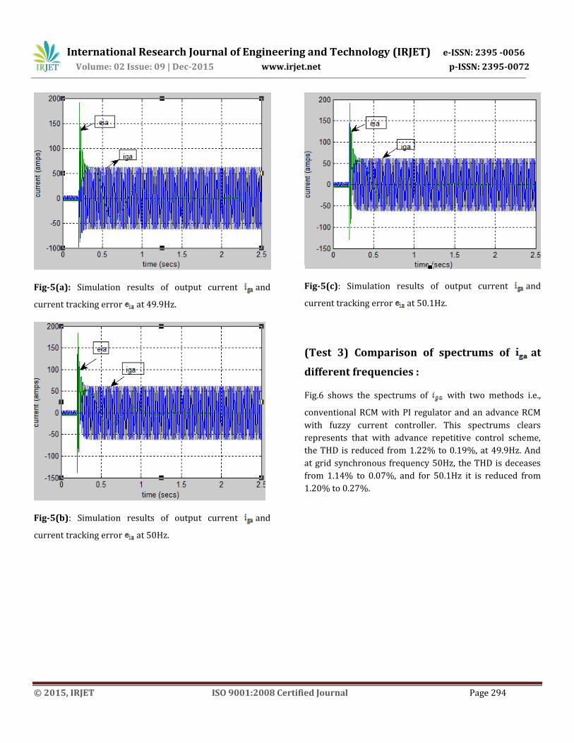
(Test 2) Effectiveness of proposed scheme
( at different frequencies) :
In order to verify the effectiveness of the proposed
scheme, the simulation results are also presented for
comparison. The output current and the current
tracking error ( at 49.9Hz, 50Hz and 50.1Hz grid
frequencies are shown in Fig.5. This diagrams clearly
shows that reaches zero at 1.5sec for synchronous
frequency 50Hz, whereas for 49.9Hz it is about at 1.8sec
and for 50.1Hz it is at around at 1.9sec. Above simulation
results easily shows the effect of the proposed scheme on
decreasing the steady-state tracing error and
compensating the harmonics of the system.
International Research Journal of Engineering and Technology (IRJET) e-ISSN: 2395 -0056
Volume: 02 Issue: 09 | Dec-2015 www.irjet.net p-ISSN: 2395-0072
© 2015, IRJET ISO 9001:2008 Certified Journal Page 294
Fig-5(a): Simulation results of output current and
current tracking error at 49.9Hz.
Fig-5(b): Simulation results of output current and
current tracking error at 50Hz.
Fig-5(c): Simulation results of output current and
current tracking error at 50.1Hz.
(Test 3) Comparison of spectrums of at
different frequencies :
Fig.6 shows the spectrums of with two methods i.e.,
conventional RCM with PI regulator and an advance RCM
with fuzzy current controller. This spectrums clears
represents that with advance repetitive control scheme,
the THD is reduced from 1.22% to 0.19%, at 49.9Hz. And
at grid synchronous frequency 50Hz, the THD is deceases
from 1.14% to 0.07%, and for 50.1Hz it is reduced from
1.20% to 0.27%.

International Research Journal of Engineering and Technology (IRJET) e-ISSN: 2395 -0056
Volume: 02 Issue: 09 | Dec-2015 www.irjet.net p-ISSN: 2395-0072
© 2015, IRJET ISO 9001:2008 Certified Journal Page 295
(a)
(b)
(c)
Fig-6(a): FFT Analysis of spectrums of with
conventional repetitive Fuzzy control at different
frequencies. (a)at 49.9Hz (b)at 50Hz and (c)at 50.1Hz.
(a)
(b)
(c)
Fig-6(b): FFT Analysis of spectrums of with
conventional repetitive PI control at different frequencies.
(a)at 49.9Hz (b)at 50Hz and (c)at 50.1Hz.

International Research Journal of Engineering and Technology (IRJET) e-ISSN: 2395 -0056
Volume: 02 Issue: 09 | Dec-2015 www.irjet.net p-ISSN: 2395-0072
© 2015, IRJET ISO 9001:2008 Certified Journal Page 296
TABLE II :Comparison of THD at Different
Frequencies
S.No System 49.9Hz 50Hz 50.1Hz
1 With PI
Controller
1.22% 1.14% 1.20%
2 With Fuzzy
Controller
0.19% 0.07% 0.20%
V. CONCLUSION
The proposed advance repetitive control scheme for fuzzy
current control based grid-connected inverter with
frequency adaptability is subjected to different frequencies
and at every point, the proposed scheme has shown better
results than conventional scheme with PI controller. It also
adopts a new FIR filter design method and can appropriate
the ideal repetitive control when the ratio of the sampling
frequency to the grid frequency varies. From simulations,
it is demonstrated theoretically that by employing fuzzy
logic controller it is even more accurate and reduce the
steady state error and harmonic distortion than any other
techniques and holds good performance.
REFERENCES
[1] IEEE Recommended Practices and Requirements for Harmonic Control in Electrical Power Systems, IEEE Std. 519-1992, Apr. 1993.
[2] Dong Chen, Junming Zhang, Member, and Zhaoming
Qian, “An improved repetitive control scheme for grid
connected inverters with frequency adaptive capability”
IEEE Transactions on Industrial Electronics, vol. 60, No. 2,
February2013.
[3]B.Zhang, D. Wang, K. Zhou, and Y. Wang, “Linear phase
lead compensation repetitive control of a CVCF PWM
inverter,” IEEE Trans. Ind.Electron., vol. 55, no. 4, pp.
1595–1602, Apr. 2008.[3] R. Kadri, J. P. Gaubert, and G.
Champenois, “An improved maximum power point
tracking for photovoltaic grid-connected inverter based on
voltage-oriented control,” IEEE Trans. Ind. Electron., vol.
58, no. 1,pp. 66–75, Jan. 2011.
[4]F. Blaabjerg, R. Teodorescu, M. Liserre, and A. V.
Timbus, “Overview of control and grid synchronization for
distributed power generation systems,” IEEE Trans. Ind.
Electron., vol. 53, no. 5, pp. 1398–1409,Oct. 2006.
[5] S. Jiang, D. Cao, Y. Li, J. Liu, and F. Z. Peng, “Low-THD, fast-transient, and cost-effective synchronous-frame repetitive controller for three-phase UPS inverters,” IEEE Trans. Power Electron., vol. 27, no. 6, pp. 2994–3005, Jun. 2012.
[6] R. Grino, R. Cardoner, R. Costa-Castello, and E. Fossas, “Digital repetitive control of a three-phase four-wire shunt active filter,” IEEE Trans. Ind. Electron., vol. 54, no. 3, pp. 1495–1503, Jun. 2007. [7] T. Hornik and Q.-C. Zhong, “H∞ repetitive voltage control of gridconnected inverters with a frequency adaptive mechanism,” IET Power Electron., vol. 3, no. 6, pp. 925–935, Nov. 2010. [8] X. Pei and Y. Kang, “Short-circuit fault protection strategy for high power three-phase three-wire inverter,” IEEE Trans. Ind. Informat., vol. 8, no. 3, pp. 545–553, Aug. 2012. [9] S. Yang, Q. Lei, F. Z. Peng, and Z. Qian, “A robust control scheme for grid-connected voltage-source inverters,” IEEE Trans. Ind. Electron., vol. 58, no. 1, pp. 202–212, Jan. 2011. [10] T. Hornik and Q.-C. Zhong, “A current-control strategy for voltage-source inverter in microgrids based on H∞and repetitive control,” IEEE Trans. Power Electron., vol. 26, no. 3, pp. 943–952, Mar. 2011. [11] S.-K. Chung, “A phase tracking system for three phase utility interface inverters,” IEEE Trans. Power Electron., vol. 15, no. 3, pp. 431–438, May 2000. [12] R. Kadri, J. P. Gaubert, and G. Champenois, “An improved maximum power point tracking for photovoltaic grid-connected inverter based on voltage-oriented control,” IEEE Trans. Ind. Electron., vol. 58, no. 1, pp. 66–75, Jan. 2011. [13] G. Shen, X. Zhu, J. Zhang, and D. Xu, “A new feedback method for PR current control of LCL-filter-based grid-

International Research Journal of Engineering and Technology (IRJET) e-ISSN: 2395 -0056
Volume: 02 Issue: 09 | Dec-2015 www.irjet.net p-ISSN: 2395-0072
© 2015, IRJET ISO 9001:2008 Certified Journal Page 297
connected inverter,” IEEE Trans. Ind. Electron., vol. 57, no. 6, pp. 2033–2041, Jun. 2010.
BIOGRAPHIES
B. Abdul Saleem currently pursuing M-
Tech in Control Systems at JNTUA
College of Engineering and Technology
Anantapuramu, Andhra Pradesh. His
area of interest is Control Systems.
Y. Vishnu Vardhan Reddy currently
pursuing M-Tech in Control Systems at
JNTUA College of Engineering and
Technology Anantapuramu, Andhra
Pradesh. His area of interest is Control
Systems