an aid to the design of ventilation for glove boxes issue 01 documents... · 6.1 glove box...
TRANSCRIPT
NUCLEAR INDUSTRY GUIDANCE
An Aid To The Design Of Ventilation For Glove
Box es
Issue 01
This guide has been endorsed by the UK Nuclear Ventilation Forum
NVF/DG002 Jan 2012
Page | ii Nuclear glove box ventilation design guide
Page | ii Nuclear ventilation design guide
FOREWORD
Comments should, in the first instance, be sent to the Nuclear Ventilation Forum at the following address:
Grant Hall Bld C21.1 AWE(A), Aldermaston Nr Reading RG7 4PR [email protected]
This document has been issued as updated guidance as contained the AECP 59 Shielded and Unshilded Glove boxes on the use of Ventilation for Nuclear Glove boxes. It has been written and compiled by a group of glove box ventilation designers from within the UK industry, consisting of:-
Grant Hall – AWE
D Booth – Motts McDonald
M Berry – Studsvik
N Randles – Sellafield Limited
R Doig – Sellafield Limited
This document is believed to be consistent with all relevant legislation and guidance, and has so far been endorsed by the following organisations:
AWE Aldermaston Urenco (UK) Ltd
Sellafield Ltd Babcock
GE Healthcare Ltd EDF Energy
Dounreay Site Restoration Ltd
Magnox Ltd
Nuclear ventilation design guide Page | iii
Nuclear ventilation design guide Page | iii
ACKNOWLEDGEMENT OF HELP IN PRODUCTION
The support of the following organizations and their nominated individuals in the production and review of this document is gratefully acknowledged:
AWE Plc – G Hall
Studsvik – M Berry
Motts McDonald - D Booth
Sellafield Limited – N Randles
Sellafied Limited – R Doig
Babcock – C Mulhall
NIS – J Axtell
Aquila – M Unwin
RECORD OF REVISIONS
Document Issue Revision Date Changes Made
Draft 01 Jan 2011 Issued for review and agreement by core glove box ventilation group and then for wider review by limited NVF members for submission to the NVF.
Issue 01 Jan 2012 Endorsed by the Nuclear Ventilation Forum
Page | iv Nuclear glove box ventilation design guide
Page | iv Nuclear ventilation design guide
CONTENTS
FOREWORD................................................................................................................................................. II
NUCLEAR VENTILATION FORUM REPRESENTATION.............. ERROR! BOOKMARK NOT DEFINED.
RECORD OF REVISIONS........................................................................................................................... III
GLOSSARY OF TERMS..............................................................................................................................VI
1. GENERAL.............................................................................................................................................. 1
1.1 SCOPE.......................................................................................................................................... 1
2. BASIC REQUIREMENTS. ..................................................................................................................... 1
3. DESIGN REQUIREMENTS. .................................................................................................................. 2
4. OBJECTIVES......................................................................................................................................... 3
5. BASIC ASPECTS OF DESIGN ............................................................................................................. 3
5.1 GENERAL ..................................................................................................................................... 3
5.2 BOX PRESSURE.......................................................................................................................... 4
5.3 GAS INLETS ................................................................................................................................. 5
5.4 INLET FLOW CONTROL.............................................................................................................. 7
5.5 FLOW RATES............................................................................................................................... 8
5.6 CORROSIVE And Other Degrading ATMOSPHERES................................................................. 8
5.7 VACUUM SYSTEMS .................................................................................................................... 9
5.8 PRESSURE CONTROL................................................................................................................ 9
5.9 INSTRUMENTATION.................................................................................................................... 9
5.10 BREACH OF CONTAINMENT.................................................................................................... 10
5.11 Extract Filter Position .................................................................................................................. 11
5.12 FIRE SAFETY ............................................................................................................................. 11
5.13 HEAT DISSIPATION................................................................................................................... 12
5.14 Proof Test And Leak Rate Requirement. .................................................................................... 12
6. VENTILATION GENERIC TYPES ....................................................................................................... 14
Nuclear ventilation design guide Page | v
Nuclear ventilation design guide Page | v
6.1 GLOVE BOX VENTILATION SYSTEMS – BOXES OPERATING UNDER A DEPRESSION ON A ‘ONCE-THROUGH’ BASIS............................................................................................................ 14
6.2 GLOVE BOX VENTILATION SYSTEMS – BOXES OPERATING UNDER A DEPRESSION ON A RECIRCULATING BASIS.............................................................................................................. 14
6.3 GLOVE BOX VENTILATION SYSTEM – BOXES OPERATING AT A POSITIVE PRESSURE............................................................................................................................................. 15
6.4 DOUBLE BOX CONTAINMENTS............................................................................................... 16
7. DETAILS OF TESTED GLOVE BOX EXTRACT SYSTEMS .............................................................. 16
7.1 CONSTANT DEPRESSION FAN SYSTEM (CDFS) .................................................................. 16
7.2 CONTROLLED CONSTANT DEPRESSION SYSTEMS (CCDS) .............................................. 19
7.3 RESISTIVE IN-BLEED SYSTEMS (RIB) .................................................................................... 20
7.4 SELF-ACTING PRESSURE REGULATOR (SAPR) SYSTEM................................................... 22
7.5 HIGH PRESSURE EXTRACT (HPE) SYSTEM.......................................................................... 23
7.6 THE VORTEX AMPLIFIER (VXA)............................................................................................... 25
7.7 POSITIVE PRESSURE GLOVE BOX VENTILATION SYSTEM ................................................ 29
8. GUIDANCE ON GENERAL GLOVE BOX VENTILATION COMPONENTS ....................................... 30
8.1 INTRODUCTION TO GLOVEBOX VENTILATION COMPONENTS.......................................... 30
8.2 GLOVE BOX FILTRATION ......................................................................................................... 30
8.3 INSTALLATION OF DEBRIS GUARDS...................................................................................... 32
8.4 LEAK TIGHT EXTRACT VALVES .............................................................................................. 32
8.5 MATERIALS FOR VENTILATIONS SYSTEMS.......................................................................... 32
8.6 CONTROLS AND INSTRUMENTATION.................................................................................... 33
8.7 ALARM ANNUNICIATORS AND SET POINT ............................................................................ 34
8.8 GLOVE BOX PRESSURE INDICATION AND ALARMS............................................................ 34
8.9 ENTRY/EXIT BOXES Used To Support Glove boxes ................................................................ 37
9. GENERAL GLOVE BOX RELATED ISSUES/EQUIPMENT. .. ERROR! BOOKMARK NOT DEFINED.
9.1 MAINTENANCE .......................................................................................................................... 39
9.2 PLANT MARKING AND EQUIPMENT DESCRIPTION.............................................................. 39
10. REFERENCES .................................................................................................................................... 39
11. ANNEX A . PRESSURE UNITS CONVERSION CHART.................................................................... 40
Page | vi Nuclear glove box ventilation design guide
Page | vi Nuclear ventilation design guide
12. ANNEX B . SUPLEMENTARY DIAGRAMS AND PHOTOGRAPHS. ................................................. 40
GLOSSARY OF TERMS
AWE Atomic Weapons Establishment
CCDS Controlled Constant Depression System
CDFS Constant Depression Fan System
DG Design Guide
HEPA High Efficiency Particulate Air
HPE High Pressure Extract
Pa Pascal
RA Radio Active
RIB Resistive Air In-Bleed
SAPR Self Acting Pressure Regulator
VA Variable Area
VXA Vortex Amplifier
Nuclear ventilation design guide Page | 1
Nuclear ventilation design guide Page | 1
1. GENERAL
1.1 SCOPE
This document covers the design principles for the ventilation of Glove boxes.
The guide has been written to detail the basic requirements for glove box ventilation to document principles used in the UK and to aid in the education of the Engineering Community.
As there are a variety of tasks which can be undertaken within glove boxes the reader will need to determine which parts of this guide apply to their system and if they should be adopted. Also existing plant operators will have established practices, which may need to be followed as appropriate.
Relevant statutory and mandatory requirements are identified, and where appropriate, reference is made to standards which will be helpful to the designer, engineer and operator.
To assist in achieving the objectives, advice is given on the following aspects of the glove box ventilation systems:
(a) Basic Requirements.
(b) Basic Aspects of Design
(c) Generic Types of Ventilation
(d) Details of Testing Glove box Ventilation Systems
(e) Guidance on General Glove box Ventilation Components
This guidance has been prepared by the Nuclear Ventilation Forum, it is therefore biased towards glove boxes for processing Radioactive and toxic materials and in some areas site specific.
2. BASIC REQUIREMENTS.
Glove boxes are sealed containments where the product or equipment is manipulated through gauntlets sealed to the glove box walls to isolate the product from the operator. This containment barrier is either required to protect the operator from the product, as in the case of handling radioactive / toxic components, or protect the product from the operator/environment to prevent product contamination, as in the case of reactive actinides
The ventilation of glove boxes must be considered as part of a larger overall ventilation system, usually covering the whole building, and with a knowledge of the design requirements for both glove boxes and laboratories. When glove boxes are used as primary containments, as for example the direct manipulation of Radio Active metals, the ventilation of glove boxes takes precedence over the laboratory ventilation systems. (For information on the ventilation of Radio Active processing areas refer to DG001 “Guidance For The Ventilation Of Radio Active Areas”. Where gloveboxes are used as secondary containment,
Page | 2 Nuclear glove box ventilation design guide
Page | 2 Nuclear ventilation design guide
such as a containment around Radioactive Gas Processes (the pipe work being the primary containment), the precedence for the interaction with the laboratory ventilation will need to be determined from an analysis of the hazard and fault scenarios
The design of the ventilation system must reflect the hazard of the materials and component forms being processed, from which will be derived Safety Functional Requirements, reliability targets, a defined containment leak tightness etc.
Because of the normally high cost associated with installing glove box lines they are limited in their number. This along with the diversity of hazards they are designed for has resulted in a large percentage of glovebox ventilation system being basically prototypes. The current guidance is to use substantiated components based on tried techniques which are now leading to the duplication of known systems.
3. DESIGN REQUIREMENTS.
Prior to embarking on the design of a glove box ventilation system the following information needs to be collected. n.b.The list below may not be exhaustive but contains the fundamental information required:-
(a) Normal Working pressure – This may be a negative or positive pressure value in the range of +250 to -500 Pa, (for readers unsure of these pressure units see also the pressure conversion chart at Annex A). For work with Radio Active and toxic materials negative pressure glove boxes are normally used in the range of -250 to -500 Pa. However, where it is essential to maintain the glove box atmosphere practically free from oxygen and moisture positive pressure glove boxes may be used. See Para 5.2.
(b) Proof Test Pressure – This is the maximum negative and positive test pressure the glove box will be designed / tested to and it should take account of identified fault scenarios. The ventilation and any pressure relief systems should be designed to retain the glove box within the proof test pressure with a suitable margin of safety. See para 5.14.
(c) Leak Rate – This is normally defined as a percent leakage per hour and is important for containment in calculating flow rates for inert boxes. The normal leakage standard for nuclear glove boxes is either 0.05 to 0.5 % box volume leakage per hour at ±1000 Pa depending on the radiological hazard. See para 5.14.
(d) Emergency Breach Flow Velocity. When a glove box suffers a breach it loses its differential pressure and has a protective flow of gas through the breach. Advice on breach inflows is given in section 5.10.
Nuclear ventilation design guide Page | 3
Nuclear ventilation design guide Page | 3
4. OBJECTIVES
The objectives of a glove box ventilation system may be many and varied, however the basic general objectives are as follows:-
(a) To supplement the glove box containment in minimising the escape of radioactive contamination into the working area and to the environment under normal, entry/exit and postulated fault conditions.
(b) The extract system is primarily required to control the atmosphere and movement of gas within the enclosed glove box and secondarily to provide protection by controlled air flow in the event of a containment breach.
(c) To provide an atmosphere within the glove box of a quality required for the process. (This is frequently a "protective inert gas" but may be laboratory air.)
(d) To provide the quantity/quality of the glove box atmosphere required to prevent excessive accumulations of undesirable gases or vapours within the boxes, for example, ozone, acid or alkaline fumes which may render the boxes unserviceable, hydrogen which may lead to a flammable atmosphere or moisture/oxygen which may be unacceptable for the in-box process concerned.
(e) To maintain the glove box at a suitable depression and in the event of a breach induce a containment flow through the breach in the shortest possible time, whilst at the same time maintaining all unbreached glove boxes on the same system under safe working conditions.
(f) To remove radioactive/toxic/noxious particulates/gaseous materials from the exhaust gases to such an extent as is necessary for its safe discharge to the environment.
5. BASIC ASPECTS OF DESIGN
5.1 GENERAL
The nature of the processes to be performed in the glove boxes mainly determines the box atmosphere conditions and hence is an important criterion in selecting the system to be used. Factors to be considered must also include:-
(a) The pressure and control method of the glove box atmosphere;
(b) The rate of air/gas flow, or the number of changes per hour of glove box atmosphere and the number of glove boxes.
(c) The required flow under postulated accident conditions, including the required protective inwards-air-flow velocity under breach of containment conditions;
(d) The nature of the glove box process(es);
(e) Distribution of the atmosphere flow within the glove box;
(f) Containment standards required.
Page | 4 Nuclear glove box ventilation design guide
Page | 4 Nuclear ventilation design guide
(g) The overall size of the ventilation system.
5.2 BOX PRESSURE
The atmosphere in RA glove boxes should be maintained at a suitable depression relative to the surrounding zone to assist the physical containment in minimising leakages of contaminated/toxic particulates/gases.
Local customs and practice may dictate that the glove box depression is designed to a set site standard. Where boxes have been installed at different depressions in the same laboratory, i.e. -400 and -500Pa, the operators have reported that there is no noticeable difference when using the containments. Where pressure switches for the High Pressure alarm systems are used the hysteresis of these devices may limit the required glove box depression. Another consideration is where a pressure gradient between glove boxes is required, to minimise the undesired spread of contamination or fumes, this may require one glove box working either above or below the normal depression.
This depression should be as small as possible having due regard to the reliability of the ventilation system in maintaining it, and for the leak tightness of the glove boxes and the associated pipework. The recommended depression for normal operation is between -250 and -500 Pa, dependent on the process involved. Too high a depression will cause gauntlets to stiffen and hamper box operators in their use for delicate operations. The maximum depression is considered to be -1000 Pa, although at this depression a significant amount of dexterity will have been lost due to the extra pressure on the gauntlets and therefore not recommended.
An alarm and automatic emergency extract system should be provided (to provide the containment breach flow), set to operate if the depression falls below or exceeds the preset level. With modern ventilation systems (and the ventilation systems prescribed in this document) the emergency extract is designed into the normal extract system increasing their reliability and giving the required breach inflow in the shortest possible time.
A pressure indicator showing the box depression, having a zero point, an emergency threshold point and a “safe” working zone should be situated within the sight of the operator at all times. Large glove boxes or those with multiple operational faces may need to have repeat pressure indicators. Alternatively, audible alarms and/or flashing beacons may be fitted to indicate an alarm condition. Simple gauges with red/green/red marked measurement areas to clearly show the “safe” working zone are used on Sellafield site.
Normally the laboratory where the glove box resides is kept under a small depression relative to the atmosphere. Therefore depending on the Glove box Extracts discharge point, should the Glove Box extract fail the glove box may then return to atmospheric pressure leaving it pressurised relative to the still depressed laboratory. Under these conditions consideration should be given to the provision of interlocks so that, under glove box ventilation failure, the laboratory area ventilation system is also switched off to prevent any significant pressure reversal between these two zones.
The glove box may be fitted with a pressure/vacuum relief device, such as an oil filled bubbler or lute (in addition to the emergency extract provisions), where vacuum / pressurised gases are used which would endanger the glove box structure should there be a blockage in the ventilation system. However there are normally compromises where these pressure/vacuum relief devices can discharge too. In addition careful consideration needs to
Nuclear ventilation design guide Page | 5
Nuclear ventilation design guide Page | 5
be taken on the maximum flow these devices can cater for. Further advice of gas inlets is given in para 5.3.
Note: There are some circumstances which dictate the need for the glove box to be kept at a positive
pressure instead of negative pressure (depression). These require special design
considerations. Limited detail for these types of boxes are contained in para 6.3.
5.3 GAS INLETS
Glove boxes have gas inlets to help provide the correct atmosphere, normally called “glove box inlets”, and process gasses to support processes normally called “process inlets”.
The simplest glove box inlets are air in-bleeds from the laboratory. These are provided to give the glove box atmosphere a change rate to dilute any evolved gases. In their simplest forms they have either one or more HEPA filters, an isolation valve and a flow control device (which could be a manual diaphragm valve or orifice plate) and an entry into the glove box. Where a glove box requires a constant flow the use of an orifice located in the inlet is very effective. The inlet valve is an isolation valve normally fully open and closed during inlet filter change out. The Sellafield preference is for a punched plastic insert as an orifice plate on inlets.
Where an inert atmosphere is required normally nitrogen or argon is supplied. This gas may either be on a once-through basis or recirculated. Experiments in the 1960’s and 70’s demonstrated that corrosion rates of Actinides of interest were lessened in the presence of a small amount of Oxygen which helps form a non-protective oxide layer. Therefore depending on the requirements there may need to be a slightly elevated oxygen level, circa 0.1 % to 2 % to allow the component to slightly oxidise to limit the corrosion from mechanisms such as hydriding. Experience has also shown that elevated oxygen level are not normally required to lessen corrosion rates with very low moisture levels in the 10’s of ppm range. However the mechanics of corrosion is a specialised subject and more pertinent to non-fuel cycle work and will therefore not be covered in this guide. As with the air in-bleeds these supplies are normally HEPA filtered to provide protection of the inlet pipework from back migration.
The Inert atmosphere is either discharged to waste (once-through), or recirculated through a decontamination and treatment plant. The flow of argon or other special gas will be economically restricted, but must be sufficient to maintain the requisite purity of the glove box atmosphere against contamination by in-leakage of air or by process off-gases and provide "blanket scavenging" of the box.
For economic reasons special atmospheres may be recirculated to glove boxes, after passing through a purification plant. Special care will be required to avoid waste of inert gases and/or fouling of the extract ducting and filters in the event of the emergency system operating due to a breach. Consideration should be given to automatic shut down and isolation of the recirculation system in this case. The design of the purification plant is outside the scope of this guide. Normally calculations will be performed to determine if recirculation and purifying the glove box gas will be more economic than using a single purge (once-through) system. However its fairly easy to perform these costing calculations which requires the future cost of the gas to be compared against the extra capital and maintenance requirements taking into account how economically the operator may actually operate the plant. Normally the difference in cost is simply related to how the operator
Page | 6 Nuclear glove box ventilation design guide
Page | 6 Nuclear ventilation design guide
actually uses the equipment, e.g. in a once through system if they lower the flow rates during periods of non use.
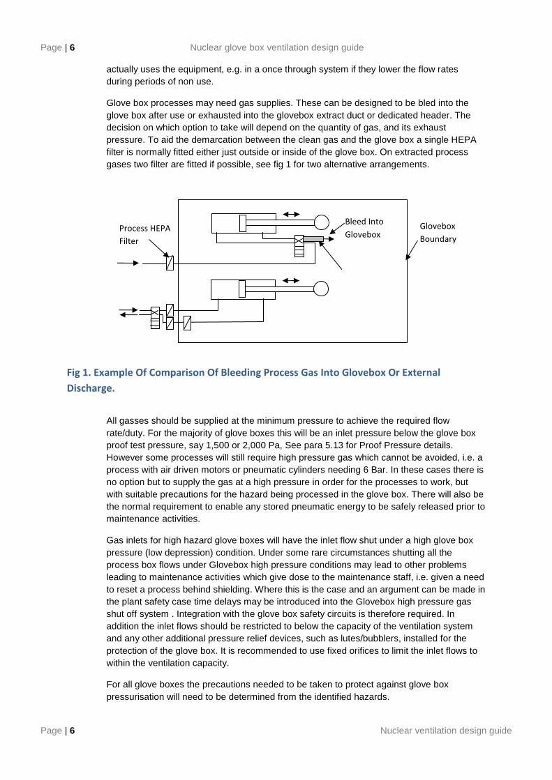
Glove box processes may need gas supplies. These can be designed to be bled into the glove box after use or exhausted into the glovebox extract duct or dedicated header. The decision on which option to take will depend on the quantity of gas, and its exhaust pressure. To aid the demarcation between the clean gas and the glove box a single HEPA filter is normally fitted either just outside or inside of the glove box. On extracted process gases two filter are fitted if possible, see fig 1 for two alternative arrangements.
Fig 1. Example Of Comparison Of Bleeding Process Gas Into Glovebox Or External
Discharge.
All gasses should be supplied at the minimum pressure to achieve the required flow rate/duty. For the majority of glove boxes this will be an inlet pressure below the glove box proof test pressure, say 1,500 or 2,000 Pa, See para 5.13 for Proof Pressure details. However some processes will still require high pressure gas which cannot be avoided, i.e. a process with air driven motors or pneumatic cylinders needing 6 Bar. In these cases there is no option but to supply the gas at a high pressure in order for the processes to work, but with suitable precautions for the hazard being processed in the glove box. There will also be the normal requirement to enable any stored pneumatic energy to be safely released prior to maintenance activities.
Gas inlets for high hazard glove boxes will have the inlet flow shut under a high glove box pressure (low depression) condition. Under some rare circumstances shutting all the process box flows under Glovebox high pressure conditions may lead to other problems leading to maintenance activities which give dose to the maintenance staff, i.e. given a need to reset a process behind shielding. Where this is the case and an argument can be made in the plant safety case time delays may be introduced into the Glovebox high pressure gas shut off system . Integration with the glove box safety circuits is therefore required. In addition the inlet flows should be restricted to below the capacity of the ventilation system and any other additional pressure relief devices, such as lutes/bubblers, installed for the protection of the glove box. It is recommended to use fixed orifices to limit the inlet flows to within the ventilation capacity.
For all glove boxes the precautions needed to be taken to protect against glove box pressurisation will need to be determined from the identified hazards.
Glovebox
Boundary
Bleed Into
Glovebox Process HEPA
Filter
Nuclear ventilation design guide Page | 7
Nuclear ventilation design guide Page | 7
The inlet ventilation gas can enter the glove box via a swirl nozzle, sparge pipe or plain entry hole. The swirl nozzle is a simple device that imparts tangential flow at its outlet, to facilitate mixing. However, the swirl nozzle has a high pressure loss, requiring a higher gas inlet pressure, which needs to be considered. The old sparge pipe system consisted of a network of pipes with small holes to evenly distribute the inlet gas. The sparge pipe system is less favoured as the small orifices along the length of the sparge pipe tend to become blocked. An alternative system uses a simple plain hole and relies on diffusion to aid gas distribution. It is believed that with all three systems, swirl nozzle, sparge pipe and plain hole, that the dominant mixing method is from diffusion, due to the very low flow velocities <0.01 m/sec a few inches from the delivery system. Therefore there is little evidence to support which system gives the best gas distribution and mixing. From a safety view the plain hole requires gas with less inlet pressure and therefore is recommended for inlet distribution systems for high hazard glove boxes. The inlet is normally positioned at the top of the glove box to simply place it in an area which will not interfere which the box process.
The location of the supply and extract may depend on how you want the Glovebox to behave. This is especially important if the Glovebox needs to be re-inerted after an air atmosphere purge.
Inlet pipework shall be easily accessible and sufficient space shall be provided to enable ease of access by operating and maintenance staff, and to prevent inadvertent damage to adjacent pipework.
5.4 INLET FLOW CONTROL
In addition to the normal isolating valves, a flow control device should be installed in the air or gas inlet, by means of:-
(a) A fixed restrictor - of a size to pass the requisite amount of gas at the designed pressure drop. A fixed restrictor is preferable to a valve which could be altered or closed accidentally. With a restrictor an installed flow indicator is optional.
(b) Control valve - for glove boxes in laboratories, where the requirements may vary, a manual control valve and flow meter may be preferred, but care must be taken to prevent accidental variation or closure of the valve. There have been reports of wear in diaphragm valves causing inlet flows to vary, however the manufactures of weir type valves have stated that finer flow control can be achieved with these devices.
A flow indication device can be fitted to the inlet to demonstrate that the inflow is correctly adjusted or means to allow the flow to be checked. Where a flow meter is installed it may cause a significant pressure drop, so a pressurised supply is required to overcome the resistance of the meter and care must be taken to prevent the possibility of pressurising the glove box by mal-operation. Flow meters which give the lowest pressure drops have been found to use pitot tubes or vortex shedding technology. Variable Area (VA) devices normally have a fairly high pressure drop. If it is planned to use VA devices then advice should be sought from the manufacture on their pressure drop before the design is finalised. The alternative is to not have a flow meter permanently installed and measure the flows at a set interval with a removable device. Care must be taken that the flow resistance of the removable device does not decrease the flow significantly so the flow reading is not within the tolerance of measurement required. With the 6 l/sec canister pancake filter a specially
Page | 8 Nuclear glove box ventilation design guide
Page | 8 Nuclear ventilation design guide
manufactured cowl is used to enable maintenance staff to measure the inlet flows on a regular basis.
Before the inlet system is designed the consequences of too much or too little flow needs to be determined to be able to choose the most suitable components.
5.5 FLOW RATES
Flow rates will be based upon the required purity, hazard potential and in some cases the heat dissipation requirements. In wet processes the flow rate may lie between 10 - 15 changes per hour just to prevent condensation; in dry processes the flow rate may lie between 0.5 - 5 changes per hour. Where heat dissipation is required, e.g. ovens or Plasma boxes, the flow rate may have to be substantially increased, e.g. 30 changes per hour or more. In each case, however, such flow rates may be determined by a design study or by comparison with past designs.
Gauntlets are tested to meet the requirements of BS EN 421 with glove box gauntlets normally having a moisture permeability less than 1g per 1.5m2. day-1.mm-1. However obviously the actual permeation will depend on if the gauntlets are bunged or rolled up. In practice there are very few available sources of practical data available for water ingress rates through glove box gauntlets. However experience has shown that when the operators use secondary gloves (surgical gloves) to prevent the build up of moisture in the box gauntlets that moisture levels in the ppm range can be obtained with 0.05 % leakage glove boxes, unleaded gauntlets and 2 to 3 changes per hour.
5.6 CORROSIVE AND OTHER DEGRADING ATMOSPHERES
Corrosive vapours and gases (from process equipment) should not be released into the box atmosphere, but should be removed within the process equipment at source, e.g. by condensers - otherwise they should be vented from the process equipment by a separate system using scrubbers, or other approved means of removing and/or neutralising their effects.
However, the escape into the box atmosphere of such vapours or gases may be unavoidable and high change rates may be required to prevent excessive concentrations in the box and extract system or the use of corrosion resistance coatings or special materials of manufacture.
Care should also be taken when selecting plastic fittings such as valves, non-return valves and regulators, for use in a corrosive environment. In such circumstances the component materials need to be able to withstand chemical, radiological and corrosion product attack.
Radioactive interaction with air causes the breakdown of the Oxygen into Ozone, which causes premature aging of some polymers. Therefore as detailed earlier glove boxes have an air change rate.
Certain other materials have been reported as having poor resistance to radiation leading to premature degradation and failure, a good example being PTFE. Given that all materials age and that many of the installed components will have un-revealed flaws it is advised that plant is designed to be able to cope with an amount of leakage as opposed to a reliance on components not to fail, i.e. that the system is intrinsically safe by design under foreseeable
Nuclear ventilation design guide Page | 9
Nuclear ventilation design guide Page | 9
fault conditions. A good example of this is the use of PTFE seals on process vessel valves. Here the valves, as part of the process, will need to be opened and closed. The exhaust header in this application should be design to cope with occasional leakage of these valves as opposed to a reliance that these valves will never leak. Obviously care needs to be taken with material selection for compatibility, expected life etc. and the quality of the polymers purchased.
5.7 VACUUM SYSTEMS
Many glove boxes have vacuum pumps as part of their process equipment. The exhausts of these pumps need to be discharged back into a suitable header designed to accommodate the discharge. If using an exhaust header the system (vacuum pump and header) should be designed so as not to pressurise the header under normal and process fault flow conditions or to be able to significantly increase the depression within the glove box.
Under some accident/fault conditions, large vacuum sources connected to equipment within a glove box could challange the integrity of the glove box. Therefore the capacity of vacuum pumps should be kept to the minimum required for the process. Similarly, the size of vacuum reservoirs must be kept to the minimum and must not be such that the integrity of the glove box is at risk if the reservoir is directly connected to the glove box under fault conditions. Also the vacuum sources must be automatically isolated when the Glove Box low pressure alarm functions and/or if the vacuum or flow conditions deviate from fixed parameters.
5.8 PRESSURE CONTROL
Normal operating pressures are controlled from the glove box extract either by connecting it to a pressure controlled extract header or by using direct operating control valves (for example Self Acting Pressure Regulators, VXA etc.). Altering the glove box inlet gas flow within its normal range should not greatly vary the glove box pressure on a well designed extract system. Designs for extract system as discussed later in this document, see Section 6.
5.9 INSTRUMENTATION
Adequate instrumentation must be provided, normally positioned immediately adjacent to the box operator, to allow for safe and efficient operation of the box services. See also para 5.2.5 for guidance for box pressure displays.
In some circumstances there may be a need to provide duplication of instrumentation in a central control room for remote monitoring.
In designing instrumentation systems account should be taken of the probable need for adequate historical recording of data.
Normally the instrumentation should be of relatively high quality and reliability and unless purposely proof tested only proven systems and equipment should be used.
The instruments will need to be calibrated at periods set by an understanding of their required duty and reliability. As such there will be a need to determine how these
Page | 10 Nuclear glove box ventilation design guide
Page | 10 Nuclear ventilation design guide
calibrations can be performed whilst maintaining isolation of the product from the maintenance personnel. Most facilities have their preferred standards on how this can be obtained, further details are contained in para 8.8. Where possible testing of complete systems, end to end, should be undertaken.
5.10 BREACH OF CONTAINMENT
Accidental breaches of the glove box containment should be considered when designing the glove box extract systems.
In the case of glove boxes working under a depression, provisions must be made to create a protective inflow of air into the box at a postulated breach of the physical containment at a velocity which will minimise egress of particulate contamination from within the glove box..
The measured containment values for inflow velocities of 1.0 and 0.5 m/sec are both extremely high when measured using SF6 tracer gas at the glove port periphery, where there is the greatest amount of turbulence. The experimental data shows the containment value at an open glove port is reduced by a factor of approximately three when reducing the inflow from 1.0 to 0.5 m/sec, hence it is the current recommendation that the optimum design breach velocity is 1.0 m/sec through an open glove port. However, from operating experience significant contamination releases have been reported when operators have removed contaminated hands from a gauntlet, caused by gauntlet punctures or from contamination released on the outer part of a glove port during gauntlet changing where the glove box ventilation can have no or little effect. It can therefore, be concluded that contamination can be released through means, which will not be protected from the breach inflow. Therefore, ventilation alone will not prevent contamination spread into the laboratory and needs to be supported by a good standard of engineering, operation and maintenance.
The glove box extract system should be as simple as possible, to give a high reliability of working when called on. To simplify the system it is normal to choose a maximum sensible breach diameter and limit the extract flow to give a containment flow through this area. In short this will only give the exact required inflow velocity through this one size breach with higher flow velocities through smaller areas and lower flow velocities through larger areas. Although this compromise appears to go against the initial advice, it allows a simplistic, reliable and workable system to be installed. Following this advice when small breaches occur, i.e. the loss of a finger on a glove, the flow velocity will be in the region of 20 m/sec if the box is normally held at a depression of -500 Pa, thus there needs to be an acceptance that using this simplistic approach the inflow velocity will vary on breach areas.
As the glove box ventilation system is designed to cope with a fairly large breech situations, normally 6 or 8 inches in diameter, when a small breaches occurs the loss in glove box depression may not be sufficient to activate the glove box high pressure alarm. This non-activation of the box pressure alarms with very small breaches can not be avoided as there will be a specific hole size, no matter how large, which will cause the high pressure alarm to activate as a simple function of the extract flow resistance and alarm set points. Normally the hole size to set off the high pressure alarm may be as large as 25 mm diameter.
When designing a glove box ventilation system the normal advice given is to allow for one glove port breach on a single box. Depending on the identified hazards and the ventilation relationship of the individual glove boxes it may be considered necessary to design for two simultaneous breaches on different glove boxes. This should be achievable with all the glove box extract systems detailed later in this document. The actual required number of simultaneous breaches will need to be determined from the actual system being designed.
Nuclear ventilation design guide Page | 11
Nuclear ventilation design guide Page | 11
Additionally, the remaining glove boxes on the same extract system as the breached glove box should remain in a safe condition, i.e. with an adequate depression.
However the employment of such protective (air) inflow systems should be carefully considered where the hazard to the operators, due to the reaction of the glove box contents with air, is greater than that due to possible activity release through a breach. In such cases positive pressure glove boxes may be used.
In the case of glove boxes working under a positive pressure, special design considerations will apply, see para 7.7.
5.11 EXTRACT FILTER POSITION
There are many factors which can affect the Breach Inflow Velocity. The main factor is the condition of the first extract filter. There are basically two methods to overcome this problem, which are:-
A, To fit the first extract filter after the breach flow control device. Here it is possible that the breach flow control device will become dirty and will need to be designed so it can be cleaned in service.
B, To fit a filter before the breach flow control device whose condition is monitored on a regular basis. With the first extract filter at the glovebox before the breach flow control device a larger allowance needs to be made for extract filter blockage and as is the case for both systems fluctuations in the extract header pressure. Therefore, if the open glove port inflow velocity was designed for an initial flow of 1.4 m/sec with clean filters this would allow some filter blockage until a minimum flow of 0.5 m/sec was obtained. Also extract filter blockage needs to be monitored at inlet flow volumes which by definition are much smaller than the required breach flow. It is advised that during inactive commissioning it is proven that filter blockage can be detected using artificially blocked filters. From past testing it has been shown that the pressure loss at the extract filter dirty condition at low inlet flows can only be detected when the glove box is not in use (movement of gloves cause pressure fluctuations). Therefore real time alarms on extract filter blockage is very difficult if not impossible to achieve. As measuring the filter condition at low flows will give a breach inflow velocity with a degree of uncertainty, due to measurement error etc. and the filter will be in service for a time period before being measured again a safety margin should be applied to the filter condition change criteria.
5.12 FIRE SAFETY
Where it proves impossible to avoid a potential fire/explosive hazard in a given process, a careful assessment must be made of the potential fire and explosion hazards and preventive design features must be incorporated accordingly.
Features must be incorporated into the design commensurate with the potential risks. These may include detectors in the glove box and/or in the extract ventilation duct, with associated alarms.

Page | 12 Nuclear glove box ventilation design guide
Page | 12 Nuclear ventilation design guide
Historically fire suppression systems have been installed in glove boxes which use the direct injection of CO2 to starve the fire of oxygen. Basically the CO2 needs to displace the oxygen in the glove box until the lower limit for combustion is reached, which for some materials may be as low as 5 % O2. This oxygen deficient atmosphere then needs to be held around the fuel until it can cool below its auto ignition point. This is usually achieved by closing the extract to retain the CO2 within the glove box, thereby pressurising the glove box. In most cases the fire will cause a large amount of airborne oxide particulate which could then enter the laboratory through any leaks if the glove box was pressurised by the CO2 or inerting gas. Simply inerting the atmosphere would be preferable to pressurising the glovebox, although to the authors knowledge no such system have been developed for fire fighting. Fire detectors in the form of heat detection cables or sensors have also historically been used. However there is little evidence that they will activate with small fires.
The main advice with regards to fire safety, which was formulated back in the 1960’s and is still true today, is that keeping the glove box tidy and free from excess flammable items will limit the possibility of fires starting and minimise their spread.
5.13 HEAT DISSIPATION.
When designing the glove box ventilation system the designer may be asked to provide for heat dissipation via the extract system. Under normal operation the expected flows through the glove box will be fairly low with that required to remove any significant amounts of heat. Normally heat generated within a glove box is rejected through dedicated heat exchangers or simply through the fabric of the glove box and not through the exhaust flow. There are cases where the flow rate has to be increased when the natural heat dissipation through the glove box wall is insufficient, e.g. where ovens, plasma torches etc have been installed. To provide any substantial heat removal, i.e. above that which can be dissipated through the box structure, the change rate may need to be increased substantially e.g. 30 ACH or more. Other processes may drive the change rate higher than 30 changes per hour, however these are not the normal. The materials of construction may need to be addressed if it is known that it may become hot over a period of time – particularly seals and polymers local to or above the heat source. The life of gasket materials is dependant on the type and amount of stress in the assembly along with other variables such as dryness and ozone levels. Because this is a very complex subject it is not covered in any depth in this guide.
5.14 PROOF TEST AND LEAK RATE REQUIREMENT.
The Glovebox “Proof” or strength test and “Leak Rate” requirements are basic parameters which must be considered when designing the Glove Box carcass , process equipment and ventilation.
There is some differences among the UK sites as to the application of the Proof Pressure test. The test is basically a strength test of the glovebox assembly and is akin to a strength test on pipework. The difference in use is that in some circumstances it is taken that the whole Glovebox assembly including gloves must survive the test and in others only that the main Glovebox shell will be in a condition to be able to be repaired. The glovebox is simply pressurised and evacuated to the required pressures, which are then held for an agreed time, usually 15 minutes, after which the box is inspected for signs of failure. The amount of pressure a glovebox can take is limited by its weakest elements which will obviously depend if Gauntlets or the Windows are fitted. Standard un-leaded 8 inch Hypalon (CSP) gauntlets start to creep at pressures around 3000 Pa and would eventually fail if left for long enough
Nuclear ventilation design guide Page | 13
Nuclear ventilation design guide Page | 13
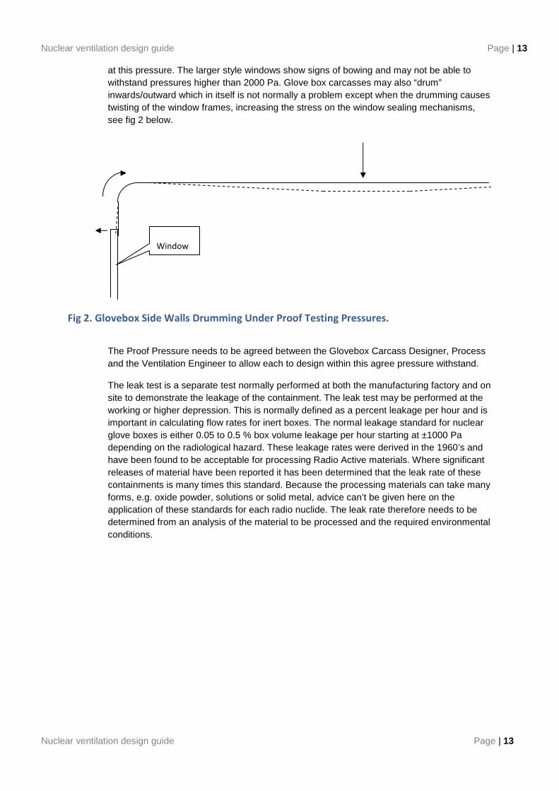
at this pressure. The larger style windows show signs of bowing and may not be able to withstand pressures higher than 2000 Pa. Glove box carcasses may also “drum” inwards/outward which in itself is not normally a problem except when the drumming causes twisting of the window frames, increasing the stress on the window sealing mechanisms, see fig 2 below.
Fig 2. Glovebox Side Walls Drumming Under Proof Testing Pressures.
The Proof Pressure needs to be agreed between the Glovebox Carcass Designer, Process and the Ventilation Engineer to allow each to design within this agree pressure withstand.
The leak test is a separate test normally performed at both the manufacturing factory and on site to demonstrate the leakage of the containment. The leak test may be performed at the working or higher depression. This is normally defined as a percent leakage per hour and is important in calculating flow rates for inert boxes. The normal leakage standard for nuclear glove boxes is either 0.05 to 0.5 % box volume leakage per hour starting at ±1000 Pa depending on the radiological hazard. These leakage rates were derived in the 1960’s and have been found to be acceptable for processing Radio Active materials. Where significant releases of material have been reported it has been determined that the leak rate of these containments is many times this standard. Because the processing materials can take many forms, e.g. oxide powder, solutions or solid metal, advice can’t be given here on the application of these standards for each radio nuclide. The leak rate therefore needs to be determined from an analysis of the material to be processed and the required environmental conditions.
Window
Page | 14 Nuclear glove box ventilation design guide
Page | 14 Nuclear ventilation design guide
6. VENTILATION GENERIC TYPES
6.1 GLOVE BOX VENTILATION SYSTEMS – BOXES OPERATING UNDER A DEPRESSION ON A ‘ONCE-THROUGH’ BASIS
These Glove boxes operate at a depression with an air or inert gas in-bleed on a ‘once-through’ basis, i.e. the in-bleed gas is not re-circulated.
The ventilation system must provide the following functions:
(a) Maintain the glove box at a depression during normal operations.
(b) Provide an enhanced inward airflow at a containment velocity through any postulated breach, whilst at the same time maintaining all other glove boxes on the same system under a safe condition (depression). Under a breach the inlet velocity is maintained from a fixed limited inlet volume, therefore inflow velocities will be relative to the breach area. The extract volume is normally sized to give 1 m/sec through an open glove port, see section 5.10 on breach flow advice.
(c) Provide adequate clean-up of all glove box extracts before discharging to the environment.
(d) Adequately cope with process faults which could lead to box pressurisation / depressurisation.
To provide the necessary clean-up or abatement before discharge to atmosphere a calculation should be performed to calculate and record the required number of stages of HEPA and/or Carbon filters.
Dependent on the magnitude of a process fault, e.g. high pressure gas or vacuum leak, the ventilation system could be designed to cater for all postulated process faults. As a secondary measure pressure switch/es detecting out-of-normal operating pressures will isolate all services to the glove box. To assure containment during breach conditions the same pressure switch/es will isolate all glove box services. To increase the safety reliability for high hazard boxes secondary pressure relief devices will be required.
6.2 GLOVE BOX VENTILATION SYSTEMS – BOXES OPERATING UNDER A DEPRESSION ON A RECIRCULATING BASIS
These Glove boxes operate at a depression with an inert gas in-bleed for process reasons or to minimise inert gas usage the in-bleed gas may be re-circulated. They are used on the AWE site.
The general requirements are the same as for the boxes operating under a depression on a once-through basis (see para 6.1.2 above), with the additional functions:
(a) When required for process reasons to avoid contamination of the recycle purge gas with air under breach conditions, to provide separation of the normal and breach extract systems.
Nuclear ventilation design guide Page | 15
Nuclear ventilation design guide Page | 15
(b) Provide the required oxygen and moisture levels as required by the process.
Note. Where there is a requirement to provide an atmosphere with a high purity, unless steps are taken to prevent back diffusion of impurities, i.e. moisture or oxygen, these will back diffuse from the extract header into the glove box. Methods to overcome back diffusion are to use long length partially inert extract headers or fully inert extract headers.
6.3 GLOVE BOX VENTILATION SYSTEM – BOXES OPERATING AT A POSITIVE PRESSURE
These Glove boxes operate at a positive pressure with respect to the laboratory with normally an inert gas or air atmosphere. This type of ventilation is used where for process reasons it is important to maintain the glove box atmosphere completely free from oxygen and moisture, or where the risk from oxygen and/or moisture in contact with the product is greater than that for a potential release to outside the glove box. When air atmospheres are used this is normally for the exclusion of particulate contamination.
Note: Because of a lack of glove box containment provided with these systems a risk assessment should be carried out to determine if a secondary containment encompassing the operator area of the glove box is required.
The ventilation system must provide the following functions:
(a) Maintain the Glove box at a positive pressure during normal operation.
(b) In the event of a breach: either
i) Isolate in-bleed, extract and all services such that the glove box interior will be under static conditions.
Or
ii) Provide an OUTWARD gas flow at a containment velocity
(c) Maintain all other glove boxes on the same system under a safe condition (depend on their process).
(d) Maintain inert gas quality (if applicable).
(e) Provide adequate clean-up of all glove box extracts before discharging to the environment.
(f) Be able to cope with process faults which could lead to glove box over pressurisation / over depressurisation.
Dependent on the magnitude of a process fault, e.g. high pressure gas or vacuum leak, the ventilation system could be designed to cater for all postulated process faults. As a secondary measure pressure switch/es detecting out-of-normal operating pressures will isolate all services to the glove box. To assure containment during breach conditions the same pressure switch/es will isolate all glove box services. To increase the safety reliability
Page | 16 Nuclear glove box ventilation design guide
Page | 16 Nuclear ventilation design guide
for high hazard boxes secondary pressure relief devices will be required.
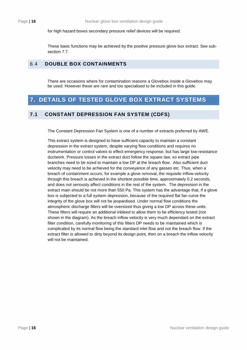
These basic functions may be achieved by the positive pressure glove box extract. See sub-section 7.7.
6.4 DOUBLE BOX CONTAINMENTS
There are occasions where for contamination reasons a Glovebox inside a Glovebox may be used. However these are rare and too specialised to be included in this guide.
7. DETAILS OF TESTED GLOVE BOX EXTRACT SYSTEMS
7.1 CONSTANT DEPRESSION FAN SYSTEM (CDFS)
The Constant Depression Fan System is one of a number of extracts preferred by AWE.
This extract system is designed to have sufficient capacity to maintain a constant depression in the extract system, despite varying flow conditions and requires no instrumentation or control valves to effect emergency response, but has large low-resistance ductwork. Pressure losses in the extract duct follow the square law, so extract pipe branches need to be sized to maintain a low DP at the breach flow. Also sufficient duct velocity may need to be achieved for the conveyance of any gasses etc. Thus, when a breach of containment occurs, for example a glove removal, the requisite inflow-velocity through this breach is achieved in the shortest possible time, approximately 0.2 seconds, and does not seriously affect conditions in the rest of the system. The depression in the extract main should be not more than 550 Pa. This system has the advantage that, if a glove box is subjected to a full system depression, because of the required flat fan curve the integrity of the glove box will not be jeopardised. Under normal flow conditions the atmospheric discharge filters will be oversized thus giving a low DP across these units. These filters will require an additional inbleed to allow them to be efficiency tested (not shown in the diagram). As the breach inflow velocity is very much dependant on the extract filter condition, carefully monitoring of this filters DP needs to be maintained which is complicated by its normal flow being the standard inlet flow and not the breach flow. If the extract filter is allowed to dirty beyond its design point, then on a breach the inflow velocity will not be maintained.
Nuclear ventilation design guide Page | 17
Nuclear ventilation design guide Page | 17
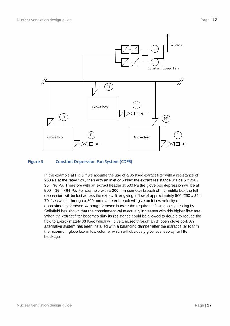
Figure 3 Constant Depression Fan System (CDFS)
In the example at Fig 3 if we assume the use of a 35 l/sec extract filter with a resistance of 250 Pa at the rated flow, then with an inlet of 5 l/sec the extract resistance will be 5 x 250 / 35 = 36 Pa. Therefore with an extract header at 500 Pa the glove box depression will be at 500 – 36 = 464 Pa. For example with a 200 mm diameter breach of the middle box the full depression will be lost across the extract filter giving a flow of approximately 500 /250 x 35 = 70 l/sec which through a 200 mm diameter breach will give an inflow velocity of approximately 2 m/sec. Although 2 m/sec is twice the required inflow velocity, testing by Sellafield has shown that the containment value actually increases with this higher flow rate. When the extract filter becomes dirty its resistance could be allowed to double to reduce the flow to approximately 33 l/sec which will give 1 m/sec through an 8” open glove port. An alternative system has been installed with a balancing damper after the extract filter to trim the maximum glove box inflow volume, which will obviously give less leeway for filter blockage.
To Stack
Glove box
PT
FI
Glove box
PT
FI
Glove box
PT
FI
Constant Speed Fan

Page | 18 Nuclear glove box ventilation design guide
Page | 18 Nuclear ventilation design guide
Figure 4 – Characteristics of a Constant Depression Fan
Other characteristics of a CDFS are:
(a) One system can serve a number of glove boxes with both varying purge-rates and purge material, namely air and inert glove boxes.
(b) In the event of a breach, air is drawn into a glove box at the containment velocity in the shortest time possible. Thus, it is one of the safest systems for Operator protection.
(c) The unaffected glove boxes on the system are maintained at a safe working depression.
(d) The system can be designed to cater for more than one breach at any one time.
Capacity Purge
Head
Constant Depression Fan Curve
∆P for Constant Depression Fan
Typical Fan Curve
Breach
∆P for
Typical
Fan

Nuclear ventilation design guide Page | 19
Nuclear ventilation design guide Page | 19
(e) All the features of Paras 7.1.3 (a) to (d) can be achieved without the use of any instrumentation, therefore, the CDFS is a passive system, has the highest reliability and fastest response possible. However high reliability is placed on the Glove box extract filter condition being able to be accurately determined and acted on. Experience has shown that the atmospheric discharge filters see little dust loading due to the glove box inlet filter, however their condition also needs to be monitored and action taken should they increase in resistance to their change point.
(f) A CDFS has two extract fans on a ‘run-and-standby’ arrangement. However, the number of fans may need to be increased dependant upon the ARM requirement. Newer designs are using a duty share fan arrangement to increase the reliability figures.
(g) The inflow velocity, at a breach, will be relative to a glove box extract filter resistance and size of breach. Therefore, glove box extract filter conditions need to be monitored. Systems are normally designed on a breach size of a single glove-port diameter.
7.2 CONTROLLED CONSTANT DEPRESSION SYSTEMS (CCDS)
The Controlled Constant Depression Fan System is one of a number of extracts preferred by AWE.
A modification of this system uses fan speed control to restore the extract header depression regardless of the flow. This will introduce added complication and reduce the reliability of the system but will allow a greater variation in flows.
With both systems it is usual to have an overall safety monitoring system which monitors the pressures within the headers and stops the fan running under too high and too low header pressures. This safety monitoring system can be SIL rated, where it is unlikely that a fan speed controller can be SIL rated.
The system can be used in a re-circulatory mode to control oxygen and moisture levels, see fig 5 for a simplified schematic. To prevent contamination of the re-circulated gas with Oxygen and Moisture from an unplanned breach the extract is automatically switched to the Purge Extract on loss of Glove box pressure. If the safety justification of the system is based around using the Purge Extract to control breach flow then the switching will need to be suitably SIL rated. In a recirculation mode the recirculation fan will need to overcome the pressure of the inlet header. If say the required extract header pressure is -500 Pa and the inlet header is +2000 Pa this fan will need to generate in excess of 2500 Pa plus, thus would probably need a fan which would easily be able to exceed the Glovebox Proof Test pressure. Therefore under fault conditions precautions will need to be taken to not endanger the box structure.
Page | 20 Nuclear glove box ventilation design guide
Page | 20 Nuclear ventilation design guide
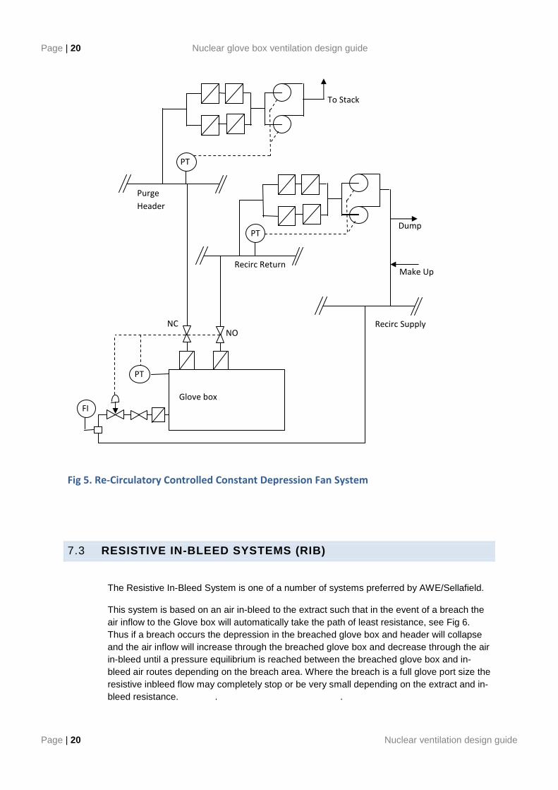
Fig 5. Re-Circulatory Controlled Constant Depression Fan System
7.3 RESISTIVE IN-BLEED SYSTEMS (RIB)
The Resistive In-Bleed System is one of a number of systems preferred by AWE/Sellafield.
This system is based on an air in-bleed to the extract such that in the event of a breach the air inflow to the Glove box will automatically take the path of least resistance, see Fig 6. Thus if a breach occurs the depression in the breached glove box and header will collapse and the air inflow will increase through the breached glove box and decrease through the air in-bleed until a pressure equilibrium is reached between the breached glove box and in-bleed air routes depending on the breach area. Where the breach is a full glove port size the resistive inbleed flow may completely stop or be very small depending on the extract and in-bleed resistance. . .
Glove box
FI
To Stack
PT
PT Dump
Make Up
PT
NC NO
Purge
Header
Recirc Return
Recirc Supply
Nuclear ventilation design guide Page | 21
Nuclear ventilation design guide Page | 21
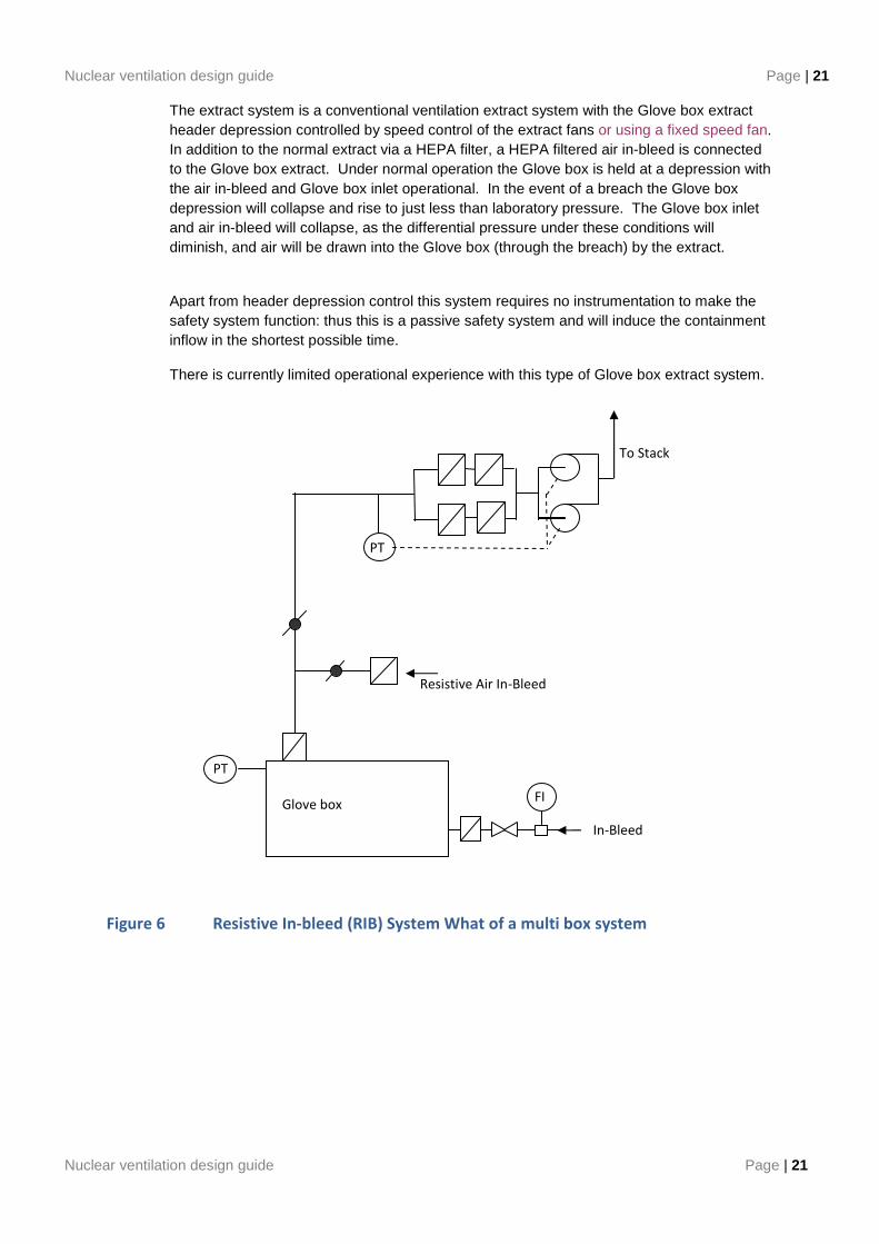
The extract system is a conventional ventilation extract system with the Glove box extract header depression controlled by speed control of the extract fans or using a fixed speed fan. In addition to the normal extract via a HEPA filter, a HEPA filtered air in-bleed is connected to the Glove box extract. Under normal operation the Glove box is held at a depression with the air in-bleed and Glove box inlet operational. In the event of a breach the Glove box depression will collapse and rise to just less than laboratory pressure. The Glove box inlet and air in-bleed will collapse, as the differential pressure under these conditions will diminish, and air will be drawn into the Glove box (through the breach) by the extract.
Apart from header depression control this system requires no instrumentation to make the safety system function: thus this is a passive safety system and will induce the containment inflow in the shortest possible time.
There is currently limited operational experience with this type of Glove box extract system.
Figure 6 Resistive In-bleed (RIB) System What of a multi box system
To Stack
Glove box
PT
PT
FI
Resistive Air In-Bleed
In-Bleed
Page | 22 Nuclear glove box ventilation design guide
Page | 22 Nuclear ventilation design guide
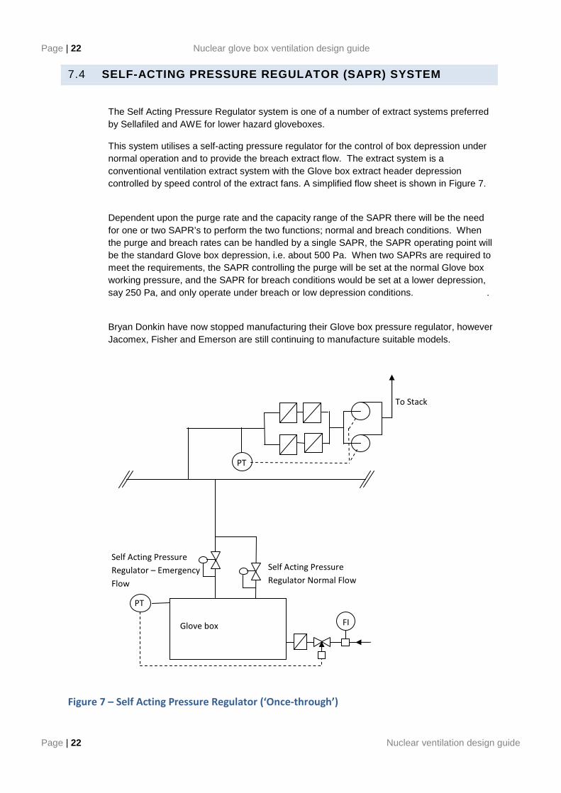
7.4 SELF-ACTING PRESSURE REGULATOR (SAPR) SYSTEM
The Self Acting Pressure Regulator system is one of a number of extract systems preferred by Sellafiled and AWE for lower hazard gloveboxes.
This system utilises a self-acting pressure regulator for the control of box depression under normal operation and to provide the breach extract flow. The extract system is a conventional ventilation extract system with the Glove box extract header depression controlled by speed control of the extract fans. A simplified flow sheet is shown in Figure 7.
Dependent upon the purge rate and the capacity range of the SAPR there will be the need for one or two SAPR’s to perform the two functions; normal and breach conditions. When the purge and breach rates can be handled by a single SAPR, the SAPR operating point will be the standard Glove box depression, i.e. about 500 Pa. When two SAPRs are required to meet the requirements, the SAPR controlling the purge will be set at the normal Glove box working pressure, and the SAPR for breach conditions would be set at a lower depression, say 250 Pa, and only operate under breach or low depression conditions. .
Bryan Donkin have now stopped manufacturing their Glove box pressure regulator, however Jacomex, Fisher and Emerson are still continuing to manufacture suitable models.
Figure 7 – Self Acting Pressure Regulator (‘Once-through’)
Glove box
PT
PT
FI
To Stack
Self Acting Pressure
Regulator Normal Flow
Self Acting Pressure
Regulator – Emergency
Flow
Nuclear ventilation design guide Page | 23
Nuclear ventilation design guide Page | 23
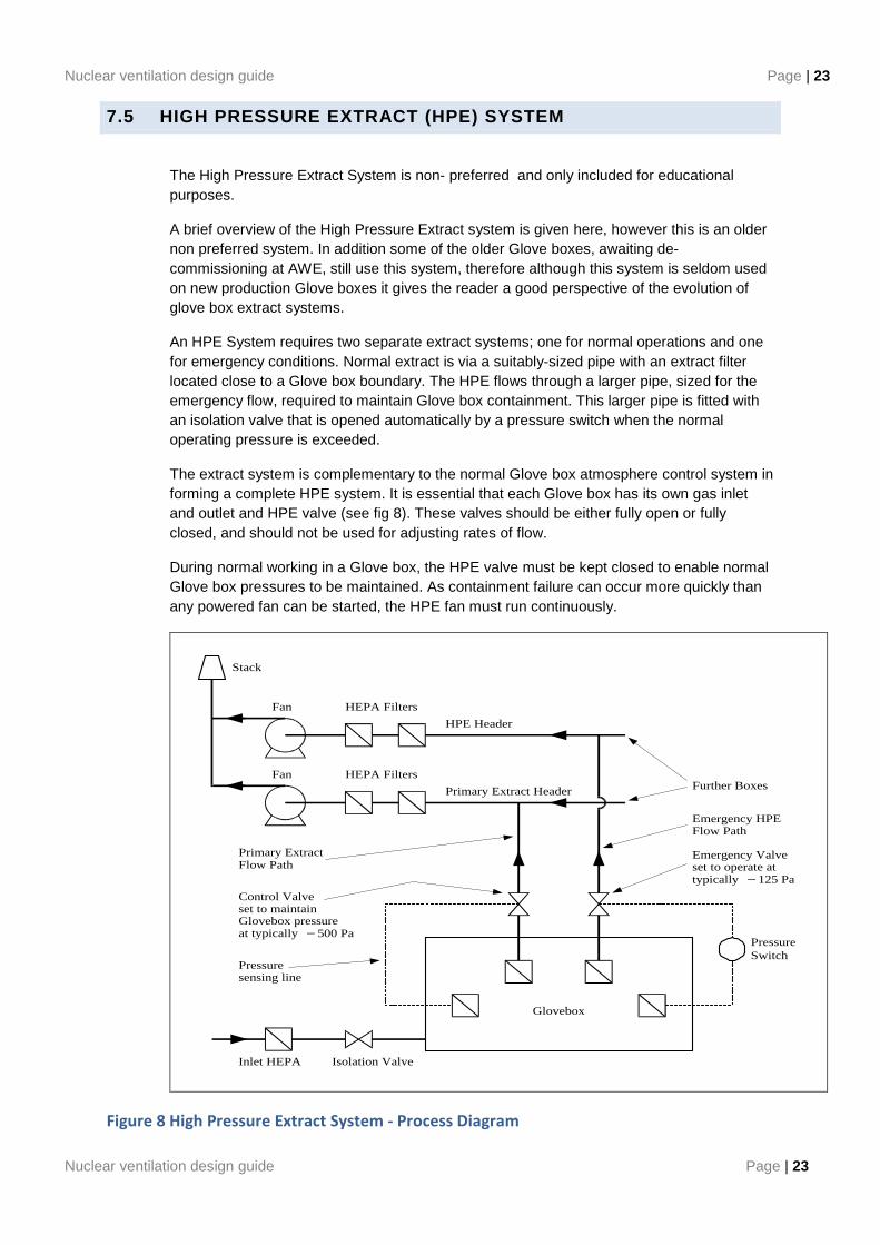
7.5 HIGH PRESSURE EXTRACT (HPE) SYSTEM
The High Pressure Extract System is non- preferred and only included for educational purposes.
A brief overview of the High Pressure Extract system is given here, however this is an older non preferred system. In addition some of the older Glove boxes, awaiting de-commissioning at AWE, still use this system, therefore although this system is seldom used on new production Glove boxes it gives the reader a good perspective of the evolution of glove box extract systems.
An HPE System requires two separate extract systems; one for normal operations and one for emergency conditions. Normal extract is via a suitably-sized pipe with an extract filter located close to a Glove box boundary. The HPE flows through a larger pipe, sized for the emergency flow, required to maintain Glove box containment. This larger pipe is fitted with an isolation valve that is opened automatically by a pressure switch when the normal operating pressure is exceeded.
The extract system is complementary to the normal Glove box atmosphere control system in forming a complete HPE system. It is essential that each Glove box has its own gas inlet and outlet and HPE valve (see fig 8). These valves should be either fully open or fully closed, and should not be used for adjusting rates of flow.
During normal working in a Glove box, the HPE valve must be kept closed to enable normal Glove box pressures to be maintained. As containment failure can occur more quickly than any powered fan can be started, the HPE fan must run continuously.
Glovebox
PressureSwitch
Isolation ValveInlet HEPA
Further Boxes
Emergency HPEFlow Path
Emergency Valveset to operate attypically −125 Pa
Control Valveset to maintainGlovebox pressureat typically −500 Pa
Pressuresensing line
Primary ExtractFlow Path
Fan HEPA Filters
Stack
Fan HEPA Filters
HPE Header
Primary Extract Header
Figure 8 High Pressure Extract System - Process Diagram
Page | 24 Nuclear glove box ventilation design guide
Page | 24 Nuclear ventilation design guide
The system relies entirely on instrumentation and the operation of control valves to achieve breach-flow conditions and, therefore, has the following disadvantages:
(a) System reliability is governed by its instrumentation.
(b) High maintenance requirements.
(c) Glove box depression must rise towards atmospheric pressure before an inflow is induced, therefore, the response to a breach is slow compared to other systems, for example two seconds may elapse before an inflow through a breach can be established.
The chosen pressure control system should have sufficient instrumentation and alarms to cover postulated accident conditions in relation to particular application needs as well as the mechanical functioning of the extract equipment.
Excess pressure or depression can be created in a Glove box when high-pressure gases or vacuum sources are connected to equipment in a Glove box and the gas or vacuum supply is suddenly ruptured within the Glove box. Under these circumstances, consideration should be given to the provision of oil lutes or other relief devices to protect the integrity of a Glove box structure and its ventilation system.
Nuclear ventilation design guide Page | 25
Nuclear ventilation design guide Page | 25
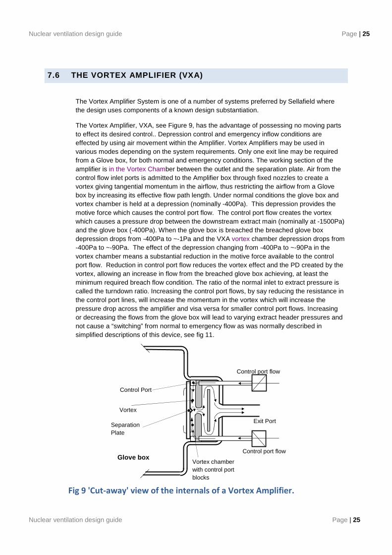
7.6 THE VORTEX AMPLIFIER (VXA)
The Vortex Amplifier System is one of a number of systems preferred by Sellafield where the design uses components of a known design substantiation.
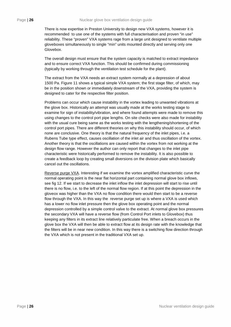
The Vortex Amplifier, VXA, see Figure 9, has the advantage of possessing no moving parts to effect its desired control.. Depression control and emergency inflow conditions are effected by using air movement within the Amplifier. Vortex Amplifiers may be used in various modes depending on the system requirements. Only one exit line may be required from a Glove box, for both normal and emergency conditions. The working section of the amplifier is in the Vortex Chamber between the outlet and the separation plate. Air from the control flow inlet ports is admitted to the Amplifier box through fixed nozzles to create a vortex giving tangential momentum in the airflow, thus restricting the airflow from a Glove box by increasing its effective flow path length. Under normal conditions the glove box and vortex chamber is held at a depression (nominally -400Pa). This depression provides the motive force which causes the control port flow. The control port flow creates the vortex which causes a pressure drop between the downstream extract main (nominally at -1500Pa) and the glove box (-400Pa). When the glove box is breached the breached glove box depression drops from -400Pa to ~-1Pa and the VXA vortex chamber depression drops from -400Pa to ~-90Pa. The effect of the depression changing from -400Pa to ~-90Pa in the vortex chamber means a substantial reduction in the motive force available to the control port flow. Reduction in control port flow reduces the vortex effect and the PD created by the vortex, allowing an increase in flow from the breached glove box achieving, at least the minimum required breach flow condition. The ratio of the normal inlet to extract pressure is called the turndown ratio. Increasing the control port flows, by say reducing the resistance in the control port lines, will increase the momentum in the vortex which will increase the pressure drop across the amplifier and visa versa for smaller control port flows. Increasing or decreasing the flows from the glove box will lead to varying extract header pressures and not cause a “switching” from normal to emergency flow as was normally described in simplified descriptions of this device, see fig 11.
Fig 9 'Cut-away' view of the internals of a Vortex Amplifier.
Control port flow
Control port flow
Vortex plate
Vortex chamber with control port blocks
Separation Plate
Glove box
Control Port
Exit Port
Page | 26 Nuclear glove box ventilation design guide
Page | 26 Nuclear ventilation design guide
There is now expertise in Preston University to design new VXA systems, however it is recommended to use one of the systems with full characterisation and proven “in use” reliability. These “proven” VXA systems rage from a large unit designed to ventilate multiple gloveboxes simultaneously to single “min” units mounted directly and serving only one Glovebox.
The overall design must ensure that the system capacity is matched to extract impedance and to ensure correct VXA function. This should be confirmed during commissioning (typically by working through the ventilation test schedule for the plant).
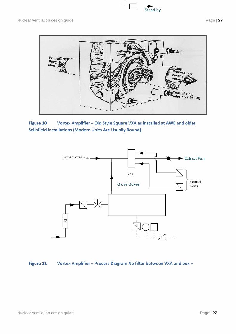
The extract from the VXA needs an extract system normally at a depression of about 1500 Pa. Figure 11 shows a typical simple VXA system; the first stage filter, of which, may be in the position shown or immediately downstream of the VXA, providing the system is designed to cater for the respective filter position.
Problems can occur which cause instability in the vortex leading to unwanted vibrations at the glove box. Historically an attempt was usually made at the works testing stage to examine for sign of instability/vibration, and where found attempts were made to remove this using changes to the control port pipe lengths. On site checks were also made for instability with the usual cure being same as the works testing with the lengthening/shortening of the control port pipes. There are different theories on why this instability should occur, of which none are conclusive. One theory is that the natural frequency of the inlet pipes, i.e. a Rubens Tube type effect, causes oscillation of the inlet air and thus oscillation of the vortex. Another theory is that the oscillations are caused within the vortex from not working at the design flow range. However the author can only report that changes to the inlet pipe characteristic were historically performed to remove the instability. It is also possible to create a feedback loop by creating small diversions on the division plate which basically cancel out the oscillations.
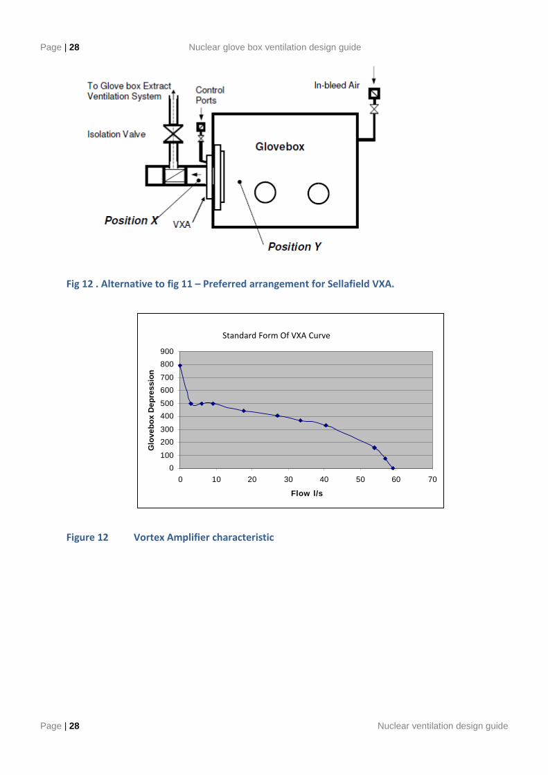
Reverse purge VXA. Interesting if we examine the vortex amplified characteristic curve the normal operating point is the near flat horizontal part containing normal glove box inflows, see fig 12. If we start to decrease the inlet inflow the inlet depression will start to rise until there is no flow, i.e. to the left of the normal flow region. If at this point the depression in the gloveox was higher than the VXA no flow condition there would then start to be a reverse flow through the VXA. In this way the reverse purge set up is where a VXA is used which has a lower no flow inlet pressure then the glove box operating point and the normal depression controlled by a simple control valve to the extract. At normal glove box pressures the secondary VXA will have a reverse flow (from Control Port inlets to Glovebox) thus keeping any filters in its extract line relatively particulate free. When a breach occurs in the glove box the VXA will then be able to extract flow at its design rate with the knowledge that the filters will be in near new condition. In this way there is a switching flow direction through the VXA which is not present in the traditional VXA set up.
Nuclear ventilation design guide Page | 27
Nuclear ventilation design guide Page | 27
Figure 10 Vortex Amplifier – Old Style Square VXA as installed at AWE and older
Sellafield installations (Modern Units Are Usually Round)
Figure 11 Vortex Amplifier – Process Diagram No filter between VXA and box –
Sock or diffuser
Glove Boxes
Stand-by
Extract Fan
Control Ports
Further Boxes
VXA
Page | 28 Nuclear glove box ventilation design guide
Page | 28 Nuclear ventilation design guide
Fig 12 . Alternative to fig 11 – Preferred arrangement for Sellafield VXA.
Figure 12 Vortex Amplifier characteristic
Extrapulated VXA Curve
0
100
200
300
400
500
600
700
800
900
0 10 20 30 40 50 60 70
Flow l/s
Glo
vebo
x D
epre
ssio
n
Standard Form Of VXA Curve
Nuclear ventilation design guide Page | 29
Nuclear ventilation design guide Page | 29
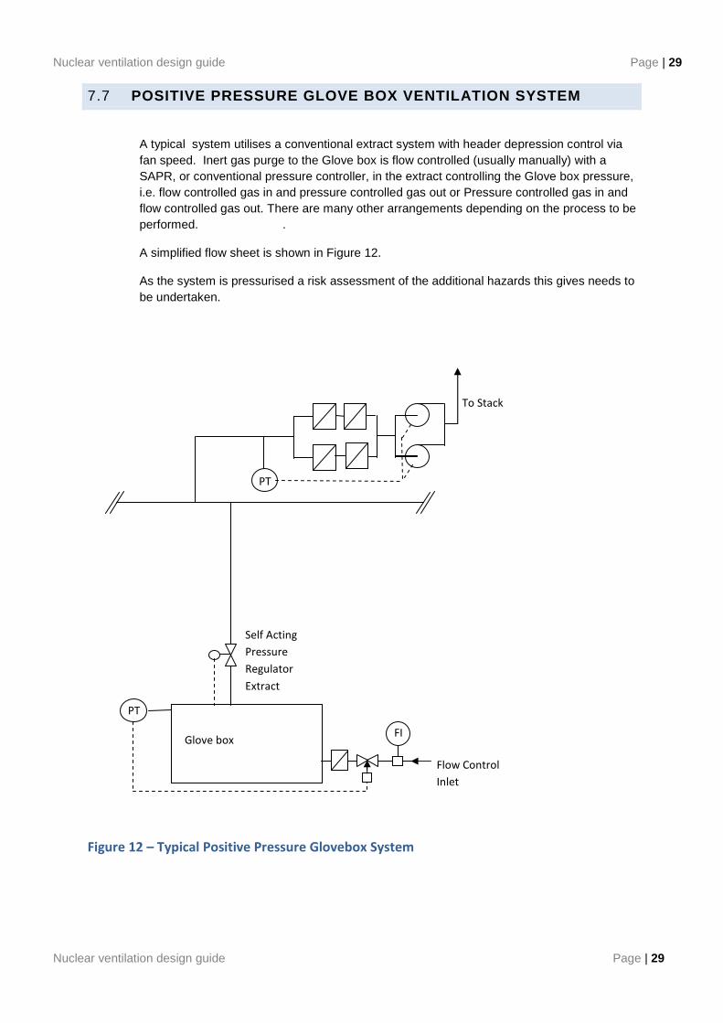
7.7 POSITIVE PRESSURE GLOVE BOX VENTILATION SYSTEM
A typical system utilises a conventional extract system with header depression control via fan speed. Inert gas purge to the Glove box is flow controlled (usually manually) with a SAPR, or conventional pressure controller, in the extract controlling the Glove box pressure, i.e. flow controlled gas in and pressure controlled gas out or Pressure controlled gas in and flow controlled gas out. There are many other arrangements depending on the process to be performed. .
A simplified flow sheet is shown in Figure 12.
As the system is pressurised a risk assessment of the additional hazards this gives needs to be undertaken.
Figure 12 – Typical Positive Pressure Glovebox System
Glove box
PT
PT
FI
To Stack
Self Acting
Pressure
Regulator
Extract
Flow Control
Inlet
Page | 30 Nuclear glove box ventilation design guide
Page | 30 Nuclear ventilation design guide
8. GUIDANCE ON GENERAL GLOVE BOX VENTILATION COMPONENTS
8.1 INTRODUCTION TO GLOVEBOX VENTILATION COMPONENTS
This section details components which are commonly used on glove box ventilation system to aid the system designer in component selection and to educate staff new to the field.
8.2 GLOVE BOX FILTRATION
The degree of filtration required to prevent the release of radioactive or hazardous material to the environment, will be determined through the Risk Assessment Process and justified in the Facility Safety Case. Normal practice is to provide one stage of non testable filtration local to a glove box, either at the glove box or a special filter box, and one or two testable stages of filtration in the designated extract plant room, depending on the calculated DF required. The in situ efficiency testing of the local glove box filters can be difficult or operationally unacceptable. At most sites there are pre-determined claims which can be made for un-testable filters. At Sellafield these are detailed in the Sellafield Release Fraction Database and at AWE in Corporate Safety Policy 865 Section 9. However, appropriate provisions may need to be made to test the extract atmospheric discharge filters in situ. The main problems with efficiency testing of these glove box filters is that the extract flow can be variable. Also the correct mixing distance between test smoke injection and sampling points needs to be maintained in what can be some tight spaces.
It is also difficult to accurately measure the Glove box Extract filter DP especially with flows as low as 0.3 l/sec. Any un-noticed dirtying may not effect the normal flow rate but may affect the resultant flow in breach condition e.g. breach flow not being achieved when required. This situation is improved where the filters are after the flow control device and glovebox extracts combined.
A range of suitable filters for use in glove boxes and manufactured to nuclear type specifications should be used - these include:
(a) 0.1 litre/second for sensing lines,
(b) 3, 5 and 6 litre/second canister for inlet branches (in-bleed)
(c) 25 litres/second for process inlet and outlet branches,
(d) 35 litres /second push-through type for extract branches,
(e) 160 litres/second push-through type for extract branches.
The inlet and outlet branches to each glove box may be fitted with suitable HEPA filters to minimise the release of radioactivity through the ventilation system during operating and static conditions. Where necessary, the filters must be fitted to accommodate flows in both directions without loss of integrity. The extract filters must be sized to cater for emergency flows. Special provision is required to deal with wet and/or acidic atmospheres; in such cases, advice should be sought at an early stage in the design process.
Nuclear ventilation design guide Page | 31
Nuclear ventilation design guide Page | 31
The purpose of the inlet filter is to clean the input air and to limit the escape of contamination in the event of loss of depression or accidental pressurisation of a glove box, leading to back-flow through the filter from a glove box. The number of filters should be determined through risk assessment. It should not be forgotten that inlet air filters may be subject to blockage with laboratory dust particles. Means to change these inlet filters due to dust blockage should be included in their design.
Note: Providing good quality building supply filtration (F8/F9) will significantly reduce the dust in laboratory air.
Note: It is AWE’s preference to use two air inlet HEPA filters to meet their safety case claims on air box inlets which also allows the outer HEPA to be changed, which will be the filter which collects the majority of the laboratory dust, while having some protection from the contamination in the glove box from the inner filter.
Normally, pressure-sensing lines to control valves, pressure switches and gauges should be fitted with HEPA filters to minimise the spread of contamination and to protect the gauge / maintenance workers from possible contamination. The filters should be positioned so that the settlement, by gravity, of particulate matter on the filter media is not possible. (Vortex Amplifiers in some forms do not use sensing lines but normally have un-testable HEPA on their control port lines.)
HEPA filters should not be subjected to high moisture levels. The easiest method to reduce glove box extract moisture levels is to provide an in-bleed of drier air as opposed to attempting to reduce the moisture levels directly. However each case will need to be decided on its merits.
A Sellafield-designed push-through combined filter housing and Vortex Amplifier assembly is shown at Figure 13 . The used filter, is pushed through into the glove box by the new filter, can be easily posted out. However experience has shown that this may be simplified to a single filter as there is normally very little in the way of contamination migration through the filter element or the end seal. Alternatively, with VXAs, a separate glove box has been used that holds all the extract filters. The choice of configuration is normally process driven.
There has been some development work on other types of filters since the break up of the last UK filter standards. It is therefore vital to determine the site preferences on which designs to use.
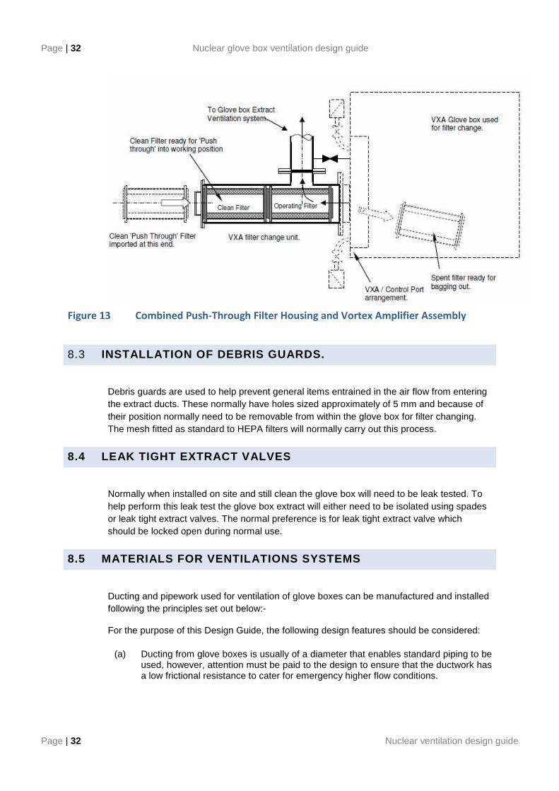
Page | 32 Nuclear glove box ventilation design guide
Page | 32 Nuclear ventilation design guide
Figure 13 Combined Push-Through Filter Housing and Vortex Amplifier Assembly
8.3 INSTALLATION OF DEBRIS GUARDS.
Debris guards are used to help prevent general items entrained in the air flow from entering the extract ducts. These normally have holes sized approximately of 5 mm and because of their position normally need to be removable from within the glove box for filter changing. The mesh fitted as standard to HEPA filters will normally carry out this process.
8.4 LEAK TIGHT EXTRACT VALVES
Normally when installed on site and still clean the glove box will need to be leak tested. To help perform this leak test the glove box extract will either need to be isolated using spades or leak tight extract valves. The normal preference is for leak tight extract valve which should be locked open during normal use.
8.5 MATERIALS FOR VENTILATIONS SYSTEMS
Ducting and pipework used for ventilation of glove boxes can be manufactured and installed following the principles set out below:-
For the purpose of this Design Guide, the following design features should be considered:
(a) Ducting from glove boxes is usually of a diameter that enables standard piping to be used, however, attention must be paid to the design to ensure that the ductwork has a low frictional resistance to cater for emergency higher flow conditions.
Nuclear ventilation design guide Page | 33
Nuclear ventilation design guide Page | 33
(b) Extract pipework inside glove boxes should always be kept to a minimum since space is limited due to process equipment and associated pipework being generally complex. Where required, pipework should be arranged to slope down to the area of highest contamination potential, thus being self-draining, and should be provided with drains, where condensation could occur. However flange gaskets may cause the pooling of condensate which could lead to increased corrosion levels.
(c) All components of the ventilation system, including ductwork, fans, valves etc, should be compatible with each other, with acidic vapours being conveyed and with the environment in which they are situated. The use of zinc or cadmium, as a protective coating on some systems and applications, may not be acceptable in some applications.
(d) Although mild steel ductwork is normally protected against corrosion by galvanising with metallic zinc, where appropriate, an additional coating such as an approved paint system often follows this treatment, to improve the ease of decontamination. However this is normally less economical than using stainless steel pipework. Therefore Stainless Steel pipework is preferred at Sellafield and AWE. Acid boxes may require the use of PTFE coated Steel.
(e) Where the glove box uses an inert or special gas back diffusion, against the extract flow, from an air extract header has in the past caused process difficulties. The normal methods used to limit this back diffusion are to either increase the extract gas velocity, increase the extract pipework duct length or install delay tanks. This is a specialised topic and can’t be covered in any length in this guide.
The piping and ducting of a glove box ventilation system generally comprises:
(a) Inlet Duct - The connection between the inlet filter and the glove box.
(b) Outlet Duct - The connection between a glove box outlet filter(s) and the main extract duct.
(c) Extract Duct - The connection between the glove box outlet duct and the main extract filters, fans and stack.
(d) Recirculation Ducts - Where applicable, the ducting or piping used to re-circulate the protective gas used in a glove box; the gas is recirculated through a cleaning unit for reuse in the glove box.
8.6 CONTROLS AND INSTRUMENTATION
General guidance for glove box ventilation systems is provided in the following paragraphs:
(a) Instrumentation should be provided such that the operational status of the ventilation system is displayed clearly and unambiguously.
(b) Hazard analysis and risk assessment will be required to determine the SIL rating of the control system for glove boxes that contain particularly hazardous materials or processes.
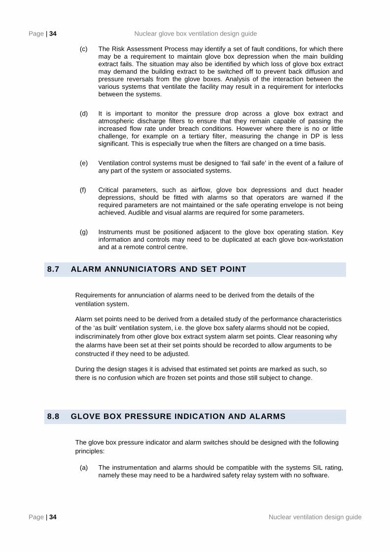
Page | 34 Nuclear glove box ventilation design guide
Page | 34 Nuclear ventilation design guide
(c) The Risk Assessment Process may identify a set of fault conditions, for which there may be a requirement to maintain glove box depression when the main building extract fails. The situation may also be identified by which loss of glove box extract may demand the building extract to be switched off to prevent back diffusion and pressure reversals from the glove boxes. Analysis of the interaction between the various systems that ventilate the facility may result in a requirement for interlocks between the systems.
(d) It is important to monitor the pressure drop across a glove box extract and atmospheric discharge filters to ensure that they remain capable of passing the increased flow rate under breach conditions. However where there is no or little challenge, for example on a tertiary filter, measuring the change in DP is less significant. This is especially true when the filters are changed on a time basis.
(e) Ventilation control systems must be designed to ‘fail safe’ in the event of a failure of any part of the system or associated systems.
(f) Critical parameters, such as airflow, glove box depressions and duct header depressions, should be fitted with alarms so that operators are warned if the required parameters are not maintained or the safe operating envelope is not being achieved. Audible and visual alarms are required for some parameters.
(g) Instruments must be positioned adjacent to the glove box operating station. Key information and controls may need to be duplicated at each glove box-workstation and at a remote control centre.
8.7 ALARM ANNUNICIATORS AND SET POINT
Requirements for annunciation of alarms need to be derived from the details of the ventilation system.
Alarm set points need to be derived from a detailed study of the performance characteristics of the ‘as built’ ventilation system, i.e. the glove box safety alarms should not be copied, indiscriminately from other glove box extract system alarm set points. Clear reasoning why the alarms have been set at their set points should be recorded to allow arguments to be constructed if they need to be adjusted.
During the design stages it is advised that estimated set points are marked as such, so there is no confusion which are frozen set points and those still subject to change.
8.8 GLOVE BOX PRESSURE INDICATION AND ALARMS
The glove box pressure indicator and alarm switches should be designed with the following principles:
(a) The instrumentation and alarms should be compatible with the systems SIL rating, namely these may need to be a hardwired safety relay system with no software.
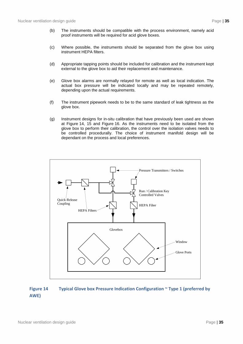
Nuclear ventilation design guide Page | 35
Nuclear ventilation design guide Page | 35
(b) The instruments should be compatible with the process environment, namely acid proof instruments will be required for acid glove boxes.
(c) Where possible, the instruments should be separated from the glove box using instrument HEPA filters.
(d) Appropriate tapping points should be included for calibration and the instrument kept external to the glove box to aid their replacement and maintenance.
(e) Glove box alarms are normally relayed for remote as well as local indication. The actual box pressure will be indicated locally and may be repeated remotely, depending upon the actual requirements.
(f) The instrument pipework needs to be to the same standard of leak tightness as the glove box.
(g) Instrument designs for in-situ calibration that have previously been used are shown at Figure 14, 15 and Figure 16. As the instruments need to be isolated from the glove box to perform their calibration, the control over the isolation valves needs to be controlled procedurally. The choice of instrument manifold design will be dependant on the process and local preferences.
Glovebox
HEPA Filter
Run / Calibration KeyControlled Valves
Pressure Transmitters / Switches
HEPA Filters
Quick-ReleaseCoupling
Window
Glove Ports
Figure 14 Typical Glove box Pressure Indication Configuration ~ Type 1 (preferred by
AWE)
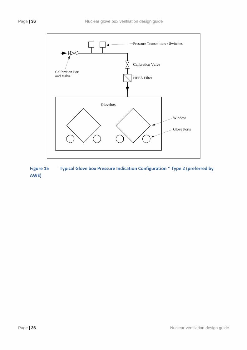
Page | 36 Nuclear glove box ventilation design guide
Page | 36 Nuclear ventilation design guide
Glovebox
HEPA Filter
Calibration Valve
Pressure Transmitters / Switches
Calibration Portand Valve
Window
Glove Ports
Figure 15 Typical Glove box Pressure Indication Configuration ~ Type 2 (preferred by
AWE)
Nuclear ventilation design guide Page | 37
Nuclear ventilation design guide Page | 37
Figure 16 Typical Glove Box Pressure Indication Configuration Type 3. (preferred by
Sellafield)
The pressure alarms should be interlocked with the process vacuum and gas supplies to remove these services with the glove box low and high pressure alarms. If a glove box has a pressurised gas inlet that could possibly cause a glove box pressurisation, this should also be interlocked with the glove box high pressure alarm.
8.9 ENTRY/EXIT BOXES USED TO SUPPORT GLOVE BOXES
Fume cupboards can be adapted to facilitate the entry and exit of components to and from glove boxes, see Fig 16. These fume cupboards should be designed generally in accordance with BS EN 14175 (Ref 02), although this standard states that it does not address fume cupboard for RA materials. The difference between the BS EN 14175 (Ref 02) fume cupboard and an entry fume cupboard is the volume flow through the entry box is normally fixed using by-pass or non sealing sashes, as apposed to Variable Air Volume systems. This is to remove the complexity from such systems and to have a constant flow which will tend to stop any back migration of RA particulate which could happen with a VAV ventilated enclosure. Air flow distribution baffles are not normally used on RA fume cupboards due to the use of smaller sash sizes and the need to perform in box contamination surveys, although could be used to improve the flow patterns if required.
Stand-by
Pressure Switches
2 x Instrument Filters
2 Port Calibration Valves
Pressure Gauge
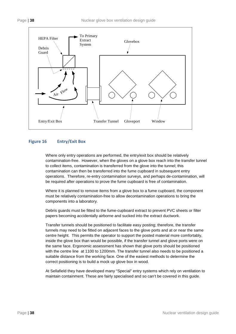
Page | 38 Nuclear glove box ventilation design guide
Page | 38 Nuclear ventilation design guide
Transfer Tunnel
Glovebox
Gloveport WindowEntry/Exit Box
HEPA FilterTo PrimaryExtractSystem
DebrisGuard
Air Flow
Figure 16 Entry/Exit Box
Where only entry operations are performed, the entry/exit box should be relatively contamination-free. However, when the gloves on a glove box reach into the transfer tunnel to collect items, contamination is transferred from the glove into the tunnel; this contamination can then be transferred into the fume cupboard in subsequent entry operations. Therefore, re-entry contamination surveys, and perhaps de-contamination, will be required after operations to prove the fume cupboard is free of contamination.
Where it is planned to remove items from a glove box to a fume cupboard, the component must be relatively contamination-free to allow decontamination operations to bring the components into a laboratory.
Debris guards must be fitted to the fume-cupboard extract to prevent PVC sheets or filter papers becoming accidentally airborne and sucked into the extract ductwork.
Transfer tunnels should be positioned to facilitate easy posting; therefore, the transfer tunnels may need to be fitted on adjacent faces to the glove ports and at or near the same centre height. This permits the operator to support the posted material more comfortably, inside the glove box than would be possible, if the transfer tunnel and glove ports were on the same face. Ergonomic assessment has shown that glove ports should be positioned with the centre line at 1100 to 1200mm. The transfer tunnel also needs to be positioned a suitable distance from the working face. One of the easiest methods to determine the correct positioning is to build a mock up glove box in wood.
At Sellafield they have developed many “Special” entry systems which rely on ventilation to maintain containment. These are fairly specialised and so can’t be covered in this guide.
Nuclear ventilation design guide Page | 39
Nuclear ventilation design guide Page | 39
9. MAINTENANCE AND MARKING
9.1 MAINTENANCE
Schedules will be compiled covering all maintenance and inspection activities that are required to ensure the availability of the plant. These schedules will be based on Manufacturers’ advice for their specific components.
The ventilation system provides a sensitive safety function and as such, routine maintenance and testing, based on general experience, must be carried out. Where the circumstances are abnormal, items that are sensitive should be examined frequently during the early period of use. Routine maintenance and test schedules should be based on the evidence collected from the various tests and examinations made, and should be reviewed to suit the test results.
Maintenance of items such as filter condition monitoring, filter changing etc. should be demonstrated during non-active commissioning.
9.2 PLANT MARKING AND EQUIPMENT DESCRIPTION
All plant and equipment must be marked and identified with its purpose and duty. Where records of routine examination are to be kept, the marking / identification must be unique to the item concerned.
All valves must be clearly labelled, in accordance with the drawings. Clear, unambiguous labelling is essential to ensure prompt and correct operator action, in the event of failure of the automatic system, and to facilitate routine maintenance.
10.REFERENCES
Reference Ref No.
001 DG001 Guidance On The Ventilation Of Radioactive Areas
002 BS EN 14175 Fume cupboards
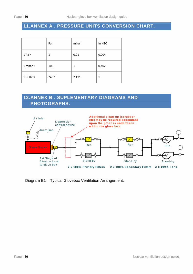
Page | 40 Nuclear glove box ventilation design guide
Page | 40 Nuclear ventilation design guide
11.ANNEX A . PRESSURE UNITS CONVERSION CHART.
Pa mbar In H2O
1 Pa = 1 0.01 0.004
1 mbar = 100 1 0.402
1 in H2O 249.1 2.491 1
12.ANNEX B . SUPLEMENTARY DIAGRAMS AND PHOTOGRAPHS.
G love B oxes
Typ ical G love Box Ventilation Syste m Arrangem ent.
Run
S tand-by Stand-by
2 x 100% Primary Filte rs
Run Run
Stand-by
2 x 100% S econdary Filte rs 2 x 100% Fans
1s t S tage o f filtration local to glove box
Depression con tro l device
Ad dition al clean-up (scrubb er e tc ) may be req uired dependant up on the process undertaken w ithin the g love bo x
A ir In let
Inert Gas supply
Diagram B1 – Typical Glovebox Ventilation Arrangement.
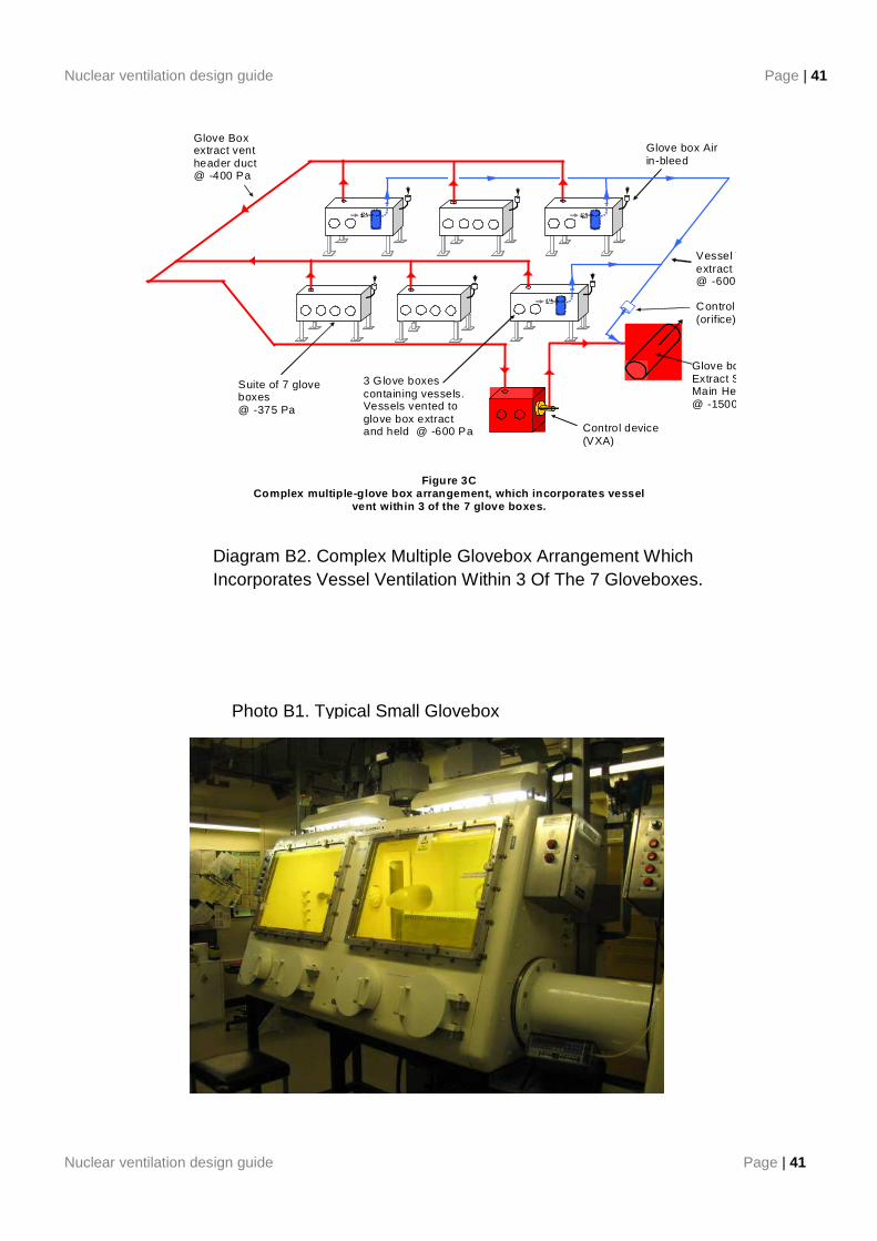
Nuclear ventilation design guide Page | 41
Nuclear ventilation design guide Page | 41
Control device (VXA)
Glove box Extract System Main Header@ -1500 Pa
Suite of 7 glove boxes @ -375 Pa
Glove box Air in-bleed
Figure 3C Complex multiple-glove box arrangement, which incor porates vessel
vent within 3 of the 7 glove boxes.
Glove Box extract vent header duct @ -400 Pa
Vessel Vent extract header@ -600 Pa Control device(orifice)
3 G love boxes containing vessels. Vessels vented to glove box extract and held @ -600 Pa
Typical Glove Box
Diagram B2. Complex Multiple Glovebox Arrangement Which Incorporates Vessel Ventilation Within 3 Of The 7 Gloveboxes.
Photo B1. Typical Small Glovebox
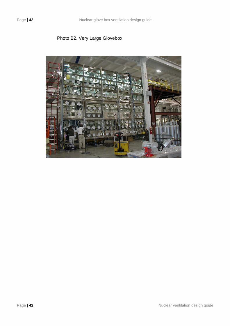
Page | 42 Nuclear glove box ventilation design guide
Page | 42 Nuclear ventilation design guide
Photo B2. Very Large Glovebox