an ‘in practice’ special cost-effective ferrite chokes and baluns · 2010-11-17 · 1 an ‘in...
TRANSCRIPT

1
An ‘In Practice’ Special
Cost-effective ferrite chokes and baluns
by Ian White, GM3SEK
PHOTO 1: Clockwise from left: low-bands ferrite choke, mid-bands choke, high-bands choke and the ferrite cores.
This article is a greatly expanded version of my monthly ‘In Practice’ column that appeared in Radcom for May 2010. That three-page article described some new designs of ferrite loaded chokes for suppressing unwanted common mode currents at HF. The same basic designs can be used in several different ways:
• As choke baluns (‘current baluns’) for coaxial feedlines
• In the shack, applied to various coaxial, mains and data cables
• Applied to consumer electronics to suppress interference on antenna feedlines, audio/video and mains cables.
These are all EMC problems, of different kinds, and the same designs of RF chokes can often be used in a number of different situations by simply changing the type of cable involved. Although the chokes have been developed using transmitting-grade coax, the basic designs have great potential for any of the above applications. If you need to use a different type of cable, eg mains or speaker cable, simply take care to copy everything else about these designs and you’ll get substantially the same dependable performance.
That word dependable is vitally important in EMC. You are often working under pressure in front of an impatient or disapproving audience, so credibility counts for a lot. If you try something that doesn’t work, they won’t understand how difficult EMC problems can sometimes be; they will simply think you don’t know what you’re doing. That credibility problem applies with family and neighbours at the home station, but just as much with fellow-amateurs in a field day or contest… and most of all, it applies at special event stations where you’re putting the credibility of amateur radio itself on show.
If you happen to be the individual on the spot, you need EMC techniques and solutions that you can depend upon to work. This article will explain why some well-known ‘solutions’ are actually not very dependable and can sometimes let you down badly. From that I will identify what actually is needed to make an RF choke perform dependably in a wide variety of different situations. Then I will present some choke designs that meet those requirements in a simple and cost-effective way, without using large and expensive ferrite cores.

2
This expanded article explains more of the technical background, beginning with an overview of what common mode currents are, and why they cause so many EMC problems. Be sure to follow up the many references on which this is based [1].
THE CURSE OF COMMON MODE
Most EMC problems can be traced to wires, cables and circuit board traces that are behaving as ‘accidental antennas’ – in other words, they are carrying RF currents into places where they don’t belong, and are also radiating like antennas. The presence of RF current where it doesn’t belong is a major cause of EMC problems, including:
• Antenna feedlines behaving as unwanted parts of the antenna which conduct RF interference back into the shack and your own radio equipment
• That same RF current flowing onward towards earth through the household mains, telephone lines and all the attached equipment.
• Interference originating in our highly polluted mains supplies, following the same pathways but in the opposite direction: flowing up the feedline to the antenna terminals at the top of the feedline, and then appearing in our receivers as high levels of noise on the amateur bands.
Those are examples of conducted interference, as they are usually due to current flowing along hard-wired connections. However, they are often made worse by the fact that any conductor carrying RF current will radiate electromagnetic fields which can then travel through space to induce currents in other conductors that appear to be unconnected, yet now they’re found to be carrying unwanted RF. That transfer of RF current without a hard-wired connection is called radiated interference, and a typical example would be a transmitter feedline carrying common-mode current, coupling unwanted RF into a TV antenna downlead or telephone wire running alongside it.
‘Common mode’ currents are given that name to distinguish them from the normal differential mode by which RF circuits operate. In differential mode, equal and opposite currents flow on two conductors, so the net radiated field from the pair of conductors is zero. This is how mains power is transmitted (the line and neutral conductors form a differential pair) and another low-frequency example is the twin cable feeding AF signals to a loudspeaker.
In RF coaxial cables, the two conductors operating in differential mode are the surface of the centre conductor and the inner skin of the shield. These two conductors carry equal and opposite currents, so they transfer RF power in differential mode, strictly confined to the inside of the cable [2]. However, the same ‘skin effect’ that helps to keep differential currents confined inside the cable is also allowing the outside of the shield to act as a totally independent third conductor, and this is the one that can carry unwanted common mode current, behaving like a single thick wire.
Twin feedline carries common mode current in a different way. The intended differential mode of operation involves equal and opposite currents on the two parallel conductors – but calling this a ‘balanced feedline’ will not automatically make it so. In fact a twin feedline is perfectly happy to carry unequal RF currents on its two conductors, and the unbalanced part of that is the common mode current. As explained in previous ‘In Practice’ columns, common mode current flows the same way on both conductors. There are many types of twin feedline, so it helps to give a few examples. In RF twin feedline, the differential currents cause no radiation into the far field, but the common mode current will cause both conducted interference and radiated interference. If the twin feedline is a speaker cable, the normal AF signal currents flow in differential mode but any induced RF currents will flow in common mode, equally on both conductors. In other non-signal applications like rotator cables, the motor power and direction feedback signals flow in differential mode, but again the unwanted RF currents that may cause interference are flowing in common mode, on all conductors together. Yet another example would be a UTP (unshielded twisted pairs) Ethernet cable, where signal currents flow in differential mode on twisted pairs, but interference currents (which may also include unwanted RF signals on the amateur bands, coming from the Ethernet cards) flow in common mode.
You see the picture: almost always, the unwanted RF signals that cause interference are flowing in common mode, while the wanted signals are in differential mode. The cure for large numbers of EMC problems is to exploit that key difference. Common mode currents can be stopped – or more

3
accurately, greatly reduced – by winding the entire cable into an RF choke. This creates a series impedance against currents flowing in common mode, but the differential mode signals don’t notice the choke at all [2].
While it is true that common mode currents cannot literally be stopped (ie they can never be reduced entirely to zero) that distinction is often academic in practical terms because many interference problems show a threshold effect. If the interference can be reduced to a level that the affected equipment can tolerate, in practical terms the problem has gone away and you can declare the case closed. This particularly applies to digital systems, where the decoding is often either completely successful or not, with a very narrow margin in between. The only other caution about the threshold effect is that you need to achieve a sufficient margin to prevent the problem reappearing as soon as your back is turned. In other words, it always helps to squelch EMC problems as completely as you practicably can.
If an RF choke is your EMC solution, how good does that choke need to be? To make a good transmitting balun? To suppress RF in the shack? To suppress RF interference to (or from) consumer electronics? The problems of EMC engineering are that every situation is different; and there is never enough technical information to be sure of success. Therefore we always need to use high-performance chokes and filters that are capable of handling almost all EMC problems, and will squelch the easier problems most thoroughly. We meet the second challenge by making maximum use of whatever facts we do know.
In EMC, and in much else besides, our most reliable friend is Ohm’s Law… so let’s see what it can tell us this time.
FIGURE 1: An effective common mode choke must dominate the upstream and downstream impedances, Z1 and Z2.
When we use an inline RF choke to suppress unwanted RF current, we are inserting some additional impedance between two impedances Z1 and Z2 that are already present in the system. Figure 1a is highly simplified but it captures the essential features of almost every EMC situation. Looking upstream of where you’re going to insert the choke, the unwanted common mode current has some kind of source which we can represent as V1 with an impedance of Z1. Looking downstream, that current is almost certainly ‘trying to find earth’, along a pathway that has a series impedance Z2. The only things that change between one case and another are the values of V1, Z1, Z2 and of course the unwanted common mode current itself, ICM [3].

4
The aim of the RF choke is to reduce ICM to some much lower level that the affected equipment can tolerate. To achieve this (Figure 1b) Ohm’s Law tells us that the impedance of the RF choke will need to be much higher than Z1 and Z2 combined – but how much higher does ZCHOKE need to be, to be certain that it will dominate the situation? As I said above, EMC offers no universal answers so we have to apply a combination of engineering and experience.
MUST DO BETTER
Experience tells us that if we’re looking for dependable solutions to a wide range of practical EMC problems, our RF chokes need to have an impedance of at least a few thousand ohms, maintained
across a wide bandwidth. A commonly quoted design criterion for common mode chokes is 500Ω;
Appendix 1 explains why 500Ω is based on unsound theory, and isn’t high enough to work
dependably in practice either. That is why more recent work tends to aim for 1000Ω and preferably higher still [1]. This article will also focus your attention on the need for the impedance to be predominantly resistive in most cases.
Many existing types of cable chokes fail to meet these more demanding (but realistic) criteria so there are some cases where they will fail to work. Air-wound chokes and ferrite loaded chokes have different weaknesses, so I will discuss each kind in turn.
AIR-WOUND CHOKES are the simple coils of cable that are often suggested as choke baluns. We tend to think of these coils as inductors, but their high-frequency performance is actually dominated by the distributed capacitance between the turns. For example, take about 2.2m of thin coax like RG8X or RG58 and wind it into a five-turn bundle of about 125mm average diameter (Figure 2,
inset). This has an inductance of about 6µH, but the capacitance between the turns is equivalent to about 9pF in parallel. So instead of an inductor, what we actually have is a high-Q parallel resonant circuit with the measured impedance characteristics of Figure 2.
FIGURE 2: Performance of an air-wound choke: notice the very sharp resonance at 21MHz. At all other frequencies the impedance is reactive (inductive below resonance,
capacitive above).
This parallel resonant circuit does not make a dependable RF choke. The impedance is only high around the resonant frequency, but much lower elsewhere. The resonant frequency is also quite sensitive to small changes affecting the capacitance between the turns, even how tightly the turns are taped together. But the fatal flaw of these chokes is that their performance is very dependent on the situation in which they’re being used. This is because the impedance of the choke consists almost entirely of either inductive or capacitive reactance, at all frequencies except the very narrow

5
region close to resonance as shown in Figure 2. Going back now to Figure 1, the reactive impedance of the choke is in series with the upstream and downstream impedances, Z1 and Z2… which also have inductive or capacitive reactances of their own. You never know from one situation to the next whether Z1 and Z2 are going to reinforce the impedance of the choke or cancel it, and in some circumstances they can even increase the common-mode current [4].
Another warning about reactive chokes is that the claimed bandwidths are often highly exaggerated,
usually based on the frequency span between 500Ω of inductive reactance and 500Ω of capacitive reactance. Using those criteria, the claimed bandwidth of the choke in Figure 2 would be “12MHz to beyond 30MHz”, which is clearly ridiculous for such a narrowband choke.
For all of these reasons, purely reactive chokes are not a dependable way to suppress unwanted common-mode currents. They may work in some situations, if you’re lucky – but “Are you feeling lucky today?” is not my idea of good RF engineering! Let’s try to find something better…
FERRITE LOADED CHOKES. To overcome the problem that reactive impedance can sometimes shift or disappear, the impedance of a dependable RF choke needs to be predominantly resistive – and also of course, very high. The advantages of resistive impedance are that it cannot be cancelled out, and it also tends to broaden the useful bandwidth of the choke. Any practical choke will also have some reactance, which is nice in situations where it works for you, but resistive impedance is the only solid foundation for dependable performance.
The only way to create a very high resistive impedance is to carefully engineer a certain amount of loss into the choke… and that is why we need the ferrite. Don’t panic about ‘loss’: unlike many other situations, resistive loss in an RF choke is a very good thing. We just need to make sure that it appears as a very high value of R in the series impedance, ZCHOKE = (R ± jX). The resistive (heat) loss in the choke equals ICM
2R, where ICM is the residual level of common-mode current that remains
after the choke has been inserted. If the choke has successfully suppressed the common mode current (and thus solved the EMC problem) then the residual value of ICM will be very low and you’ll be unlikely to notice significant heating in the ferrite. This is why we’re aiming for an R value of
several thousand ohms, rather than a lower value like 500Ω which experience has proved to be inadequate (see Appendix 1).
Ferrite chokes with a resistive impedance less than 1000Ω are at much greater risk of underperforming and overheating. Many of these chokes were designed to meet that inadequate
target of 500Ω, and some commercial examples have also suffered further cost-cutting, eg by using smaller quantities of ferrite and failing to use the correct materials. As I said above, poorly performing chokes may work for ‘soft’ EMC problems but they don’t have enough impedance to handle anything challenging. If the choke is not working effectively, then in some transmitting applications the residual value of ICM may be large enough to cause overheating of the ferrite; and if the material reaches the a temperature only a little above 130°C its magnetic permeability will collapse, allowing ICM to increase even further – the choke will almost literally ‘crash and burn’ [5].
At this point I need to emphasize: ‘ferrite’ means literally ferrite and nothing else – specifically not dust iron! [6]
6
CAN DO BETTER
Yes, we can! To make a really good ferrite choke, you need to do two things:
1. Choose the right grade of ferrite, one that actually has some loss at the operating frequency.
2. Construct your choke to create just the right amount of coupling between the ferrite material and the magnetic field around the cable.
Neither of those things will happen by blind luck. There are hundreds of different grades of ferrite with widely differing magnetic properties. They all look the same so you have to know exactly what grade you’re using; and that will mean buying ‘named ferrite’ from a reliable source [6]. With the help of a Vector Network Analyser, it then becomes quite easy to develop some effective ferrite-loaded chokes [7]. But if you don’t have access to that level of test equipment, the only route to dependable performance is to copy someone else’s designs.
Most of the published designs [1] originate in the USA and use ferrite cores manufactured by the Fair-Rite Corporation. None of these cores are cheap, and here in Europe they will cost about twice as much due to shipping, VAT and all the other markups and ‘handling charges’. We can reduce costs a little by shopping carefully, combining orders with other amateurs and taking advantage of special offers on shipping; but the cost of ferrite is always going to be a much bigger consideration on this side of the Atlantic.
Jim Brown, K9YC has been particularly active in developing designs for high performance ferrite loaded chokes, and his PDF papers and PowerPoint presentations are essential reading [1]. To make sure that his chokes can handle even the most stressful applications at power levels up to
1500W, K9YC aims for very high values of resistive impedance (preferably 5000Ω or even more). However, that superb performance is achieved by using large ferrite cores, sometimes four or five at a time, which are not affordable at European prices. Thus we are forced to look for alternative designs, that cost a lot less but can still handle the large majority of balun and EMC problems. In other words, we’re looking for cost-effectiveness.
Strings of ferrite beads are definitely not cost-effective. Ferrite beads can usually take only one ‘turn’ of cable (one pass through the centre hole = 1 turn) and each individual bead generates quite a low impedance, so a high impedance will need an awful lot of beads in series. Ten or 20 beads will only give enough impedance to handle the easy, soft problems; for dependable performance, think 40 or 50 large beads and then work out the cost! As K9YC and many others have pointed out, the cost-effective way to achieve a high impedance is to use multiple turns through the same core, because the impedance will then increase with the number of turns squared [8]. But multiple turns of thick coax, mains or rotator cable will require a large core… and we’re straight back into the problem of expensive ferrite.
For some years I have been looking for a way out of this, and inspiration came with the 2010 ARRL Handbook. The Transmission Lines chapter features some new choke designs by George Cutsogeorge, W2VJN, that use a small number of relatively low-cost ferrite cores threaded onto a coil of cable (Photo 1). These cores have an oval central hole, 26x13mm, which will take several turns of thin transmitting coax like RG8X, or similar-sized cable of any other type. And although they are made by Fair-Rite in the USA, these particular cores don’t have to be specially imported; they are readily available as stock items from Farnell UK at about £2.70 each [1].
These cores are made of Fair-Rite’s number 43 (#43) material, which is a good general-purpose suppression material for HF use. It isn’t quite as good as #31 at the low end of the spectrum, or #61 towards 30MHz, but probably the best all-rounder. Equally to the point, this particular size and shape of core is only available in #43 at present, and it supports a wide range of different choke designs covering 1.8 to 30MHz. Once again I must stress that availability and cost have a much higher priority outside the USA.
7
PRACTICAL CHOKE DESIGNS
That W2VJN design concept has opened the way to a range of cost-effective ferrite chokes that can tackle the large majority of balun and other EMC problems across the HF spectrum. The three chokes in Photo 1 are only examples of what can be done; each choke delivers a high resistive impedance over at least a 2:1 frequency range using only two or three of the oval Fair-Rite cores. The performance isn’t as good as Jim Brown’s biggest and best, but they are a major advance over most of the balun and EMC chokes that we’re using at present. Because all these chokes use the same ferrite cores, the most cost-effective strategy is to keep a stock of the bare cores, and then quickly run up a suitable choke for any cable that needs one.
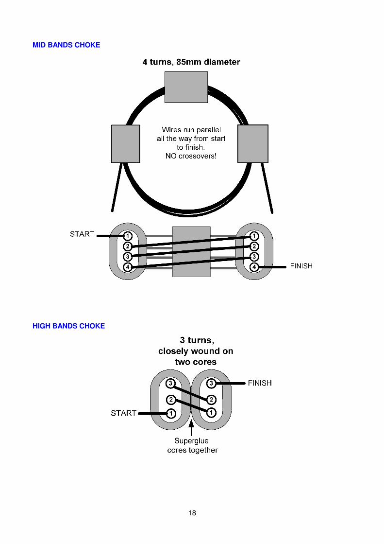
The key dimensions for the three HF-band chokes are given in Table 1, and further construction details are in Appendix 2.
Turns Mean diameter Cores
Low bands 5 125mm 3
Mid bands 4 85mm 3
High bands 3 Close wound 2, glued side-by-side
All ferrite cores are Fair-Rite 2643167851 = Farnell 1463420. No substitutes allowed!
TABLE 1: Dimensions of the three HF ferrite chokes
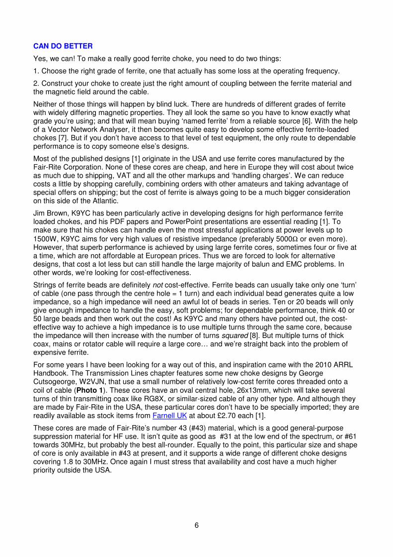
LOW BANDS CHOKE. When two or three of our ferrite cores are threaded onto the flat 5-turn coil that was described earlier (Photo 1, left) the narrowband 21MHz choke from Figure 2 is transformed into a highly effective broadband choke covering 1.8–3.8MHz.
FIGURE 3: Performance of the Low Bands choke with three ferrite cores.

8
Figure 3 shows the measured performance. The blue trace is the resistive part of the impedance,
which is about 4000Ω on Top Band and 3000Ω on 80m. The total impedance (red trace) includes some additional inductive reactance at lower frequencies and capacitive reactance at higher frequencies. Despite the drive to reduce ferrite costs, I found that three cores gave a worthwhile increase in the resistive part of the impedance, compared with the two cores used in the W2VJN’s original design. On 160m you will probably see the full benefit of the inductive reactance as well, because the system in which the choke is installed is unlikely to involve feedline lengths of greater than 40m (which would be necessary to create an opposing capacitive reactance). However, feedlines longer than a quarter-wavelength become increasingly likely at higher frequencies as noted above.
As you see from Figure 3, the two amateur bands are actually on the skirts of the resonance peak, so that peak needs to be positioned fairly accurately to produce similar performance on both bands. To obtain the correct amount of distributed capacitance between turns of the coil, you’ll need to follow the detailed assembly instructions with care.
MID BANDS CHOKE (Photo 1, top right). To cover 5, 7 and 10MHz, still use three cores but reduce the coil diameter and the number of turns. Figure 4 (next page) shows excellent performance across all three bands, and this same choke may also be usable for easier EMC problems down to 3.5MHz and up to 14MHz. For optimum wideband coverage it is essential that the turns of cable are stacked vertically inside the cores with no crossovers, exactly as shown in Photo 1.
HIGH BANDS CHOKE. For 14–30MHz coverage, this design concept is somewhat running out of steam but we aren’t beaten yet. If two of the same cores are superglued together side-by-side as shown in Photo 1, lower right, three turns will make quite a respectable choke for a 20–10m beam. The impedance (Figure 5, next page) isn’t quite as high as the lower-frequency chokes at their very best, but it is substantially resistive across the whole 14–30MHz range. In terms of ‘value for ferrite’ this two-core choke will at least equal a straight string of 40 to 50 beads! Two or more of these chokes can also be daisy-chained together if you need a higher impedance, still at a reasonable cost and with superb bandwidth.
FIGURE 4: Performance of the Mid Bands choke.

9
FIGURE 5: Performance of the High Bands choke, wound on two ferrite cores side by side.
CASCADING CHOKES
If you want more impedance or a wider bandwidth, you can cascade any of these chokes in series along the cable. The interactions are quite mild and the impedances always seem to reinforce each other (rather than destroying each other, as always happens with reactive air-wound chokes) as the following examples will show.
LOW + MID BANDS. Figure 6 shows the measured results of cascading these two chokes.
Figure 6: Low Bands and Mid Bands chokes cascaded.

10
The measured impedance is more than 6000Ω at 1.8MHz, more than 3000Ω of which is resistive.
The combined impedance then remains above or around 5000Ω, all the way up to 15MHz. I haven’t yet examined the detailed interactions between the two chokes but the combined result is better than a simple sum of the two impedances – and all this from the six small ferrite cores.
MID + HIGH BANDS. Figure 7 shows a similar reinforcement between these two chokes, giving a consistently high and predominantly resistive impedance covering 3.5–30MHz. (On this scale, it’s easy to lose sight of the very good performance down as far as 3.5MHz; only Top Band is left out.)
Figure 7: Mid Bands and High Bands chokes cascaded.
(The Low Bands and High Bands chokes can also be cascaded in a similar way, although the resonances of the two chokes don’t overlap very much, allowing the combined impedance to dip to
about 2000Ω at 7MHz.)
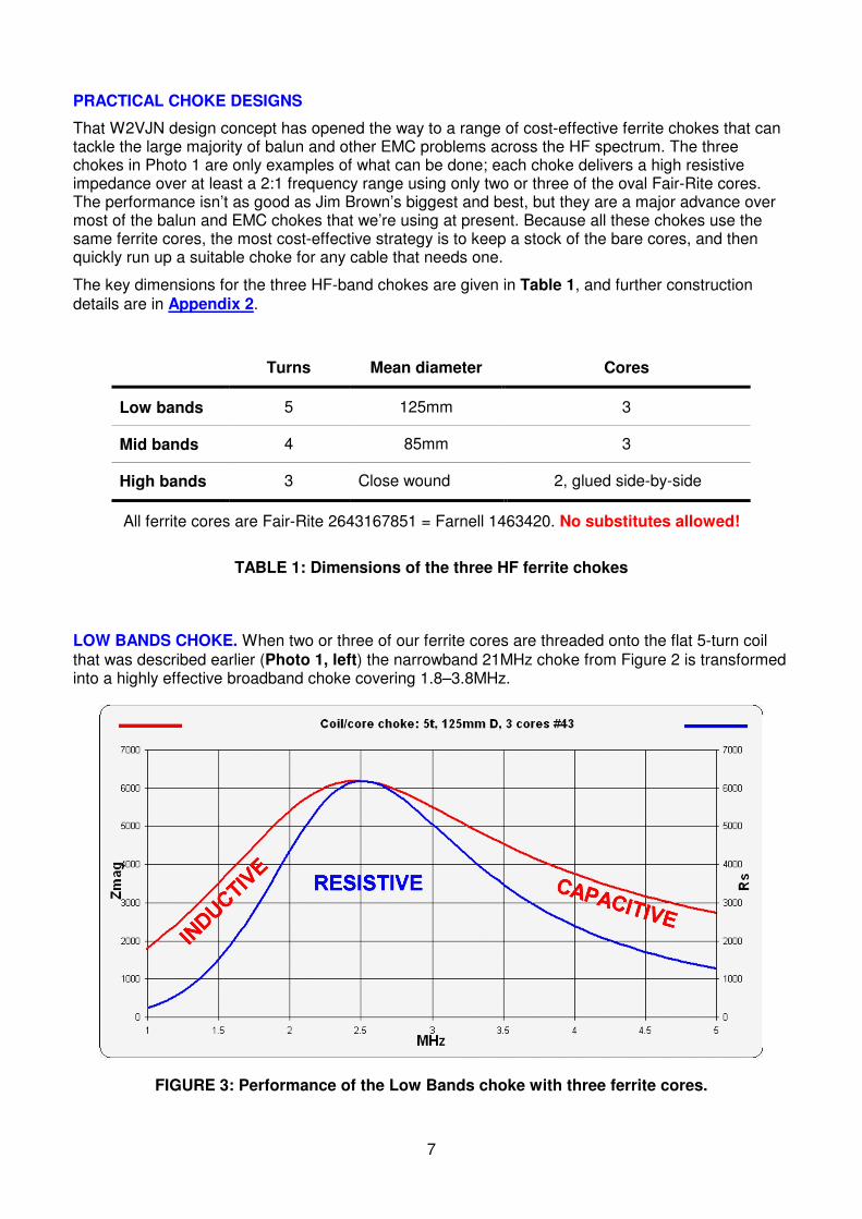
ALL THREE CHOKES. For Figure 8 (over page) the Y axes had to be expanded to 10,000Ω rather
than the customary 7000Ω. As you see, the three chokes together provide a very high impedance all the way from 1.8MHz to 30MHz. Up to 21MHz the impedance is predominantly resistive, and then
from 21–30MHz the resistive part falls from about 7000Ω to 2500Ω (the remainder being capacitive reactance).
This set of chokes uses a total of eight of our standard cores, but it delivers a lot of performance for less than £25-worth of ferrite. However, another practical drawback is that it is quite difficult to package these three chokes neatly; possibly something could be developed using 120mm PVC pipe as a former for the largest choke and an enclosure for the other two.
11
Figure 8: All three chokes cascaded.
AND IF THAT DOESN’T WORK…
These chokes are only EMC tools – they are no substitute for that blend of theoretical background and practical experience which we call ‘know-how’. So if one of these chokes doesn’t solve your particular EMC problems, your next moves should probably be…
• Make sure you are using the choke in the right place! (Not going to do any good on the wrong cable, is it?)
This could be the subject of several more articles, but if the antenna is fed with coax all the way, you should definitely start with a choke at the far end, right at the terminals of the dipole or other driven element; in other words, the choke is being used as a current balun. If the antenna is fed only part-way with coax which then changes to twin feedline, eg the typical G5RV, wind your choke on the coax at that transition point (this is your only chance to force that twin feeder into a balanced condition, because twin feeder is not self-balancing!).
If that single choke is not enough, another generally useful location is where the coax feedline enters the shack. Also don’t forget both ends of the rotator cable, which can also be carrying substantial levels of common mode RF current.
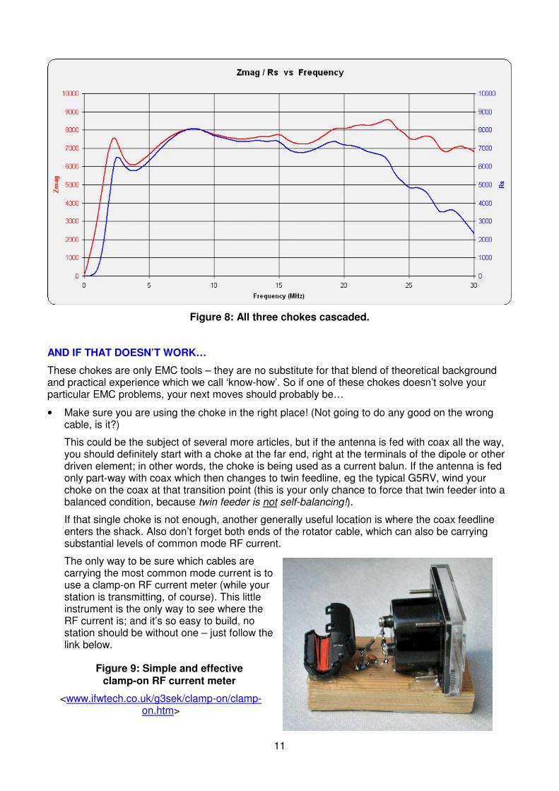
The only way to be sure which cables are carrying the most common mode current is to use a clamp-on RF current meter (while your station is transmitting, of course). This little instrument is the only way to see where the RF current is; and it’s so easy to build, no station should be without one – just follow the link below.
Figure 9: Simple and effective clamp-on RF current meter
<www.ifwtech.co.uk/g3sek/clamp-on/clamp-on.htm>

12
If you’re sure that the choke is in the right place but it still doesn’t solve the problem, you need to investigate why the common mode currents are so large. Really severe common mode problems are often caused by a definite fault – for example, a PL259 with a disconnected coax shield. If your system has that kind of fault, then a choke is the wrong cure (even if it shows some signs of working). The right cure is to find the fault!
• Remember everything you do, everything you try – for even if it doesn’t work, it can all add to your EMC experience… if you let it.
FURTHER DEVELOPMENTS
Finally, back to the choke designs. We are definitely onto something: this design concept is already delivering high performance at an affordable cost, and more work will surely drive both factors closer to the optimum. A number of experimenters are already finding other ways to make feedline chokes using these same cores [9] and they also show great promise for other applications such as filtering the mains supply to the shack (see the May 2009 column).
My preliminary conclusions about the relationships between coil dimensions, the numbers of cores and the resulting performance are that:
• A larger coil diameter will give a lower resonant frequency, but also a narrower bandwidth with generally more reactive impedance away from resonance. Even so, two or three cores on quite a small coil of cable is a very cost-effective way to generate a large choking impedance on the lower bands.
• A smaller coil diameter with more of the circumference inside the ferrite cores will give a wider bandwidth and a more generally resistive impedance. This is not surprising since it takes the design in the direction of a bead choke that has its entire length encased in ferrite. However, winding cable several times through the same core is a much more efficient way to do it, because it takes full advantage of the (turns)
2 multiplication effect.
This is all wide open for experimentation, using these and possibly some other types of ferrite cores – so if you have the necessary testgear [7], go to it.
On the other hand, if you need some high-performance RF chokes right now, go directly to Table 1 and check Appendix 2 for more construction details.

13
Notes and references
[1] Web links
Steve Hunt, G3TXQ:
• Common Mode Chokes <http://www.karinya.net/g3txq/chokes> Excellent visual presentation of which chokes work and which one’s don’t, and antenna modelling to show how purely inductive chokes can go wrong.
Jim Brown, K9YC:
• RFI, Ferrites, and Common Mode Chokes For Hams <http://audiosystemsgroup.com/RFI-Ham.pdf> An ever-growing compendium of theory, measurements, choke designs and good practical advice.
• Transmitting Chokes <http://audiosystemsgroup.com/NCDXACoaxChokesPPT.pdf> A shorter PowerPoint presentation.
• Understanding and Eliminating RF Interference <http://audiosystemsgroup.com/RFIHamNCCC.pdf> Another good PowerPoint presentation, covering much the same material from a different viewpoint.
• <http://audiosystemsgroup.com/publish.htm> – Jim’s extensive publications page.
Chuck Counselman, W1HIS:
• Common Mode Chokes <http://www.yccc.org/Articles/W1HIS/CommonModeChokesW1HIS2006Apr06.pdf> How one man transformed his ‘noisy’ location to a quiet one, using heroic quantities of ferrite.
Tom Rauch, W8JI:
• <http://www.w8ji.com> – use the keyword choke to search the whole site. It’s all worth reading.
Owen Duffy, VK1OD:
• A Method for Estimating the Impedance of a Ferrite Cored Toroidal Inductor at RF <http://vk1od.net/blog/?p=806> Analysis using frequency-dependent complex permeability (K9YC makes some very similar points).
• <http://www.vk1od.net> – again, don’t limit yourself to just one page. Owen’s entire site is well worth reading.
The cores!
• Fair-Rite part number 2643167851 <http://www.fair-rite.com/newfair/pdf/15th_Edition_FairRite_catalog_Cable_and_Connector.pdf#page=22>
• Available in the UK from Farnell, at: <http://uk.farnell.com/fair-rite/2643167851/ferrite-core-160ohm/dp/1463420?Ntt=1463420>

14
[2] In Practice, Radcom December 2009.
[3] Needless to say, there are many deeper layers of complexity. The conventional ‘circuit diagram’ depiction in Figure 1 is highly simplified, and can be misleading if you’re not careful. The ‘earth’ symbols do not necessarily represent a common ground point, for they may be at different places a significant fraction of a wavelength apart. If antennas are involved, some of the connections around the source V1 will involve ‘displacement current’, ie transfers of energy by electromagnetic radiation rather than conduction along physical wires.
Nevertheless, these complications don’t contradict the basic points:
• The choke is being inserted between two pre-existing impedances, upstream and downstream
• At all relevant frequencies, the impedance of the choke needs to be much greater than the impedances Z1 and Z2 between which it is inserted.
[4] The common-mode reactance of a feedline depends on its electrical length, in wavelengths at the frequency in use. For electrical lengths up to 0.25λ the common-mode reactance is inductive, rising to a peak at exactly 0.25λ; but then it flips to become capacitive, falling back towards to zero at 0.5λ. The cycle then repeats with every additional 0.5λ. (Remember that we are talking here about the reactance of the outside surface of the coax, considered as a thick single wire. In common mode, the velocity factor will generally be higher than the value quoted in the data sheet for the differential mode which happens inside the coax.)
With practical amateur feedline lengths, inductive reactance will be common at 1.8MHz and 3.5MHz, but capacitive reactance will become much more common as the wavelength decreases. You may be lucky to find a high common-mode reactance on one particular band, but that will almost certainly mean a very low value on a different band at twice the frequency. In other words, it’s a lottery; and if you operate all HF bands with the same antenna and feedline, you’re almost sure to have common-mode problems on at least one band.
If you now insert an air-wound choke, which itself can have either an inductive or a capacitive reactance, it only increases the confusion. Sometimes it will help, but there are also cases where ‘the wrong kind of reactance’ will actually make the common-mode current worse (see G3TXQ’s website referenced above).
[5] A few more details:
• The permeability of these ferrite materials decreases with temperature, and the Curie temperature (at which the magnetic permeability collapses completely) is surprisingly low – not far above 130°C.
• The overheating effect is sometimes mistakenly called ‘saturation’ but is actually due to simple resistive (I
2R) losses in the magnetic material, which are occurring at flux levels some way below
saturation.
I should also emphasise again that these effects are not a problem in high performance chokes, because the residual levels of ICM are too low to cause significant ICM
2R heating.
[6] “Ferrite” means specifically ferrite! Dust iron toroids like the T-200-6 are no good for this application because their permeability and their losses are both too low. Dust iron cores are good for tuned circuits but quite useless for high-performance broadband chokes, which need a higher permeability and a higher (but tightly controlled) level of loss. This can only be achieved by using certain specific types of ferrite.

15
[7] This development work requires the ability to measure very high impedances in the presence of stray inductance and capacitance in the test setup. That in turn requires a Vector Network Analyser that can be calibrated to compensate for those strays, and can measure high impedances with verifiable accuracy. Unfortunately this is beyond the capabilities of R-X antenna analysers like the MFJ-259B.
The measurements reported here used a home built N2PK Vector Network Analyser and two
completely different test jigs. After calibration with a 50Ω standard, and taking care to maintain a
consistent layout geometry, a 10kΩ chip resistor could be measured in either test jig with an accuracy of a few percent, up to at least 30MHz.
However, I could not reproduce the impedance measurements reported in the ARRL Handbook, especially those for air-wound chokes which seem very optimistic to me.
[8] The main thing to note is that multiple turns through the same core will build up the impedance much more rapidly than adding beads to a string. As usual, moving up to higher frequencies brings additional details, for we find that the permeability of ferrites is frequency-dependent and accompanied by losses and resonances within the core itself. Owen Duffy, VK1OD gives a good description of complex permeability and Jim Brown, K9YC shows the effects of core resonances at VHF (and sometimes below) – see the web links in note [1]. But once again, those added details do not detract from the main point: the value and cost-effectiveness of using multiple turns on a large ferrite core.
[9] Special thanks to G3TXQ, M0JEK, VK1OD, VK4OQ, K6MHE and all the authors referenced above – and above all to W2VJN for the original idea.

16
APPENDIX 1: WHAT’S WRONG WITH 500ΩΩΩΩ?
What’s wrong is that the 500Ω criterion doesn’t apply here. It was developed for a different type of balun in a different application.
In a so-called ‘voltage balun’ or ‘transformer balun’ there are transformer windings in parallel with
both the input and the output. If the operating impedance is 50Ω, it is quite reasonable to say that the
winding impedances must be at least 10 x 50Ω to avoid upsetting the VSWR. That is where the
500Ω criterion comes from… and that is all it means.
It is meaningless to apply this 500Ω criterion to common mode chokes because they operate on a totally different principle. It can also be hazardous, as we shall shortly see.
The diagram above shows the ‘bench-top torture test’ for a common mode choke (we can represent any common mode choke as two closely coupled windings, regardless of the actual type of cable). This setup is testing how well the choke can function as a current balun, in an extreme situation
where the link A-B has deliberately connected the ‘wrong’ side of the 50Ω load to ground. If the choke is working well, the output is completely floating – there isn’t a ‘right’ or a ‘wrong’ side any more. That’s the whole point of having a balun, isn’t it?
This particular situation is the worst case for an imperfect choke balun because the impedance of the
choke winding appears in parallel with the load. It’s true that if ZCHOKE is 500Ω or more, it will not have much effect on the VSWR… but VSWR isn’t the problem here!
The real problem is the heat dissipation in the resistive part of ZCHOKE. If that was as low as 500Ω, anything up to 1/11
th of the total RF power could be lost in heating the choke. That wouldn’t matter in
a location like a TV downlead, where induced RF currents are quite low, but in transmitting
applications that same choke could easily burn up. For current baluns, the 500Ω criterion is thus shown to be “incompetent, irrelevant and immaterial”.
That is why we need to aim for impedances of at least a few thousand ohms in the resistive part. Everyone who has thought this through from first principles would agree on that.
Fortunately, real-life balun applications are not as severe as the bench-top torture test as drawn above, because the link A-B does not exist at the top of the feedline; and there is nothing that could be called ‘ground’ up there either. In reality the whole thing floats at some unknown RF potential, relative to the real ground some distance away. This way of thinking about the problem leads us into far too many unknown voltages and impedances, which is why the main article chooses to focus on currents instead: how much common mode current do we have, and how much series impedance is needed to suppress it to a much lower value?
A final reminder: always remember that we are thinking about common mode currents and impedances. For a coaxial feedline, ‘common mode’ means currents flowing on the outside of the
shield which behaves as a ‘thick single wire’; the 50Ω impedance is irrelevant because it applies only to the differential mode that exists inside the feedline (the only relevance of the differential mode is that together with the transmitter it helps to set up a driving voltage V1 at the feedpoint).
17
APPENDIX 2: CONSTRUCTION DETAILS
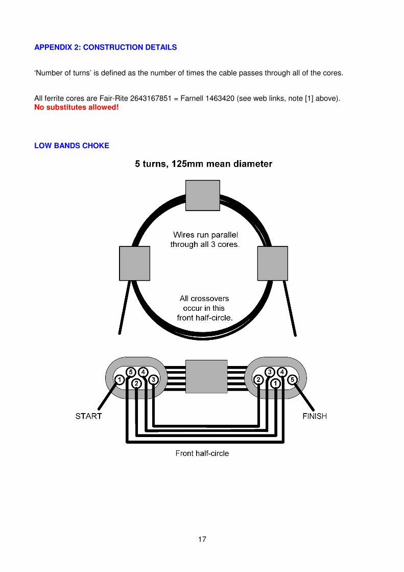
‘Number of turns’ is defined as the number of times the cable passes through all of the cores.
All ferrite cores are Fair-Rite 2643167851 = Farnell 1463420 (see web links, note [1] above). No substitutes allowed!
LOW BANDS CHOKE
18
MID BANDS CHOKE
HIGH BANDS CHOKE
19
Copyright notice
This article is an expanded version of my ‘In Practice’ column for May 2009. The information and images that were published in Radcom are © 2010 Radio Society of Great Britain.
All additional content in this document is © 2010 IFWtech Limited.
You are welcome to use the RF choke designs described in this article for amateur, experimental and non-commercial purposes; but they may not be manufactured commercially without permission.
Issue 2.2, 1 October 2010.