an analysis of small-scale wind pump design for … analysis of small-scale wind pump design for use...
TRANSCRIPT

An Analysis of Small-Scale Wind Pump Design
for Use in Developing Countries
A Major Qualifying Project submitted to the faculty of Worcester Polytechnic
Institute in partial fulfillment of the requirements for the Degree of Bachelor of Science
BJS – WI13
Submitted by: Gregory Ford Victoria Hewey
Nicholas Lima
Submitted to: Project Advisor: Professor Brian Savilonis
April 23, 2013

i
Table of Contents Table of Contents ........................................................................................................................................... i
List of Figures ............................................................................................................................................... iii
List of Tables ................................................................................................................................................ iv
Abstract ......................................................................................................................................................... 1
Chapter 1: Introduction ............................................................................................................................... 2
Chapter 2: Background ................................................................................................................................ 3
A Brief History and Development of Wind Power .................................................................................... 3
Advantages of Wind Power ................................................................................................................... 5
Disadvantages of Wind Power .............................................................................................................. 5
Current Applications of Wind Energy ................................................................................................... 6
Basic Wind Power Theory ......................................................................................................................... 7
Turbine Site Selection ........................................................................................................................... 9
Wind Turbines and Machinery ................................................................................................................ 12
Categories of Wind Turbines ............................................................................................................... 12
Types of Wind Turbines ...................................................................................................................... 15
Wind Turbine Comparisons .................................................................................................................... 19
Darrieus Turbine ................................................................................................................................. 20
Savonius Rotor .................................................................................................................................... 21
Basic Water Pumping Theory .................................................................................................................. 22
Water Pump Comparisons ...................................................................................................................... 24
Piston Pump ........................................................................................................................................ 27
Centrifugal Pump ................................................................................................................................ 28
Rope Pump .......................................................................................................................................... 29
Current Wind Pump Designs ................................................................................................................... 30
Chapter 3: Design ....................................................................................................................................... 33
Location Selection and Specifications ..................................................................................................... 33
Wind Turbine Selection and Design ........................................................................................................ 37
Design of Darrieus Turbine ................................................................................................................. 39
Design of Savonius Turbine ................................................................................................................. 40
Pump Selection and Design .................................................................................................................... 42

ii
Connecting the Turbine and the Pump ................................................................................................... 44
Gearbox Power Transmission ............................................................................................................. 44
Belt Drive Power Transmission ........................................................................................................... 45
Prototype Construction .......................................................................................................................... 46
Savonius Turbine Construction ........................................................................................................... 46
Darrieus Turbine Construction ............................................................................................................ 47
Rope Pump Construction .................................................................................................................... 50
Idealized Final Design for Fraserburg, South Africa ............................................................................ 52
Material Availability and a Package Concept ...................................................................................... 54
Chapter 4: Results and Analysis ................................................................................................................. 56
Testing and Results ................................................................................................................................. 58
Cost Comparison ..................................................................................................................................... 61
Conclusions and Recommendations ....................................................................................................... 62
Appendix A: Cost Breakdown ..................................................................................................................... 64
Appendix A-1: Wind-Device Materials .................................................................................................... 64
Appendix A-2: WPI Testing Rope Pump Materials .................................................................................. 65
Appendix B: Fabrication Instructions ......................................................................................................... 66
Appendix B-1: Wind Turbine ................................................................................................................... 66
Appendix B-1a: Center Shaft ............................................................................................................... 66
Appendix B-1b: Fiberglass Darrieus airfoils ........................................................................................ 69
Appendix B-1c: Wind turbine base ..................................................................................................... 73
Appendix B-2: Rope Pump ...................................................................................................................... 75
Appendix B-2a: Rope Pump Wheel and Shaft ..................................................................................... 75
Appendix B-2b: Rope Pump Frame ..................................................................................................... 76
Appendix B-2c: Faucet and Rope ........................................................................................................ 79
Appendix B-2d: Completed Assembly ................................................................................................. 82
Appendix C: Mathcad ................................................................................................................................. 83
Appendix C-1: Savonius-Darrieus and Rope Pump Calculations ............................................................. 83
Appendix C-2: Piston Pump Calculations ................................................................................................ 85
Appendix C-3: Multistage Centrifugal Pump Calculations ...................................................................... 86
References .................................................................................................................................................. 89
iii
List of Figures
Figure 1: Panemone Windmill Design. .......................................................................................... 3 Figure 2. A Dutch tower mill (1400 A.D.). (Telsonet) ................................................................... 4 Figure 3: A chart comparing rotor power coefficients and tip speed ratios (Wortman, 1983) ....... 9
Figure 4. A wind map for the state of Massachusetts (U.S. Department of Energy, 2012) ......... 10 Figure 5. Location characteristics for wind turbines (Wortman, 1983) ........................................ 11 Figure 6. Two examples of horizontal axis wind turbines (Rehman, 2012) ................................. 13 Figure 7. An example of a Darrieus vertical axis wind turbine (Wortman, 1983) ....................... 15 Figure 8: A multi-bladed wind turbine design (Rye, 2008) .......................................................... 16
Figure 9: An aerocam wind turbine design (Inhabitat, 2008) ....................................................... 16 Figure 10: A drawing of a Panemone wind turbine (Wikipedia, 2009) ........................................ 17 Figure 11. A Darrieus type VAWT (howstuffworks.com, 2006) ................................................. 18
Figure 12: Helix Wind Turbine (Helix Shaped Vertical Wind Turbines, 2009) .......................... 19 Figure 13. A simple Savonius concept (Experiments with Model Wind Turbines, 2012). .......... 21 Figure 14: Estimated pump head, water volumes, and associated wind pump rotor size
(Smulders, 1996) ........................................................................................................................... 23 Figure 15: Comparison of Mechanical Wind Pump to Other Pump Devices (Smulders, 1996) . 24
Figure 16: Different pump types and their characteristics (Gasch & Twele, 2012) .................... 25 Figure 17 Applications for different pump flow rates and heads (Gasch & Twele, 2012) ........... 26 Figure 18. A piston pump. (Gasch & Twele, 2012)...................................................................... 28
Figure 19. Cross section of a centrifugal pump (Werner Sölken, 2013) ...................................... 28 Figure 20: WOT Low-Tech Rope Pump (WOT, 2012) ............................................................... 30
Figure 21: Multi-blade driven piston pump (MacGarry) ............................................................. 31 Figure 22. Fraserburg, South Africa (marked with an A) (Google Maps, 2013) ......................... 34
Figure 23. Wind classes at 10 meters (Classes of Wind Power Density at 10m and 50m) .......... 35 Figure 24. Water availability in Africa (NERC, 2011) ................................................................. 36 Figure 25. H-Darrieus and "eggbeater" Darrieus turbines (Darrieus Wind Turbine) ................... 39
Figure 26: Symmetric NACA 0015 Airfoil Shape ...................................................................... 40 Figure 27: Extruded NACA 0015 Airfoil .................................................................................... 40 Figure 28: Right Angle Worm Gear (Gears and Stuff, 2006)...................................................... 44 Figure 29: Right Angle Belt Drive (Matthews) ........................................................................... 45 Figure 30: Savonius Turbine ........................................................................................................ 46 Figure 31. Acrylic NACA 0015 cross section .............................................................................. 47 Figure 32. Completed Savonius-Darrieus wind turbine. .............................................................. 49
Figure 33: Final Constructed Rope Pump .................................................................................... 51 Figure 34: Pump Shaft and Tire Texture ..................................................................................... 52
Figure 35: Fraserburg Wind Pump Design. ................................................................................. 53 Figure 36: WPI Testing Design ................................................................................................... 54 Figure 37. Volume flow versus revolution speed. ........................................................................ 56 Figure 38. Spring constants........................................................................................................... 59 Figure 39. Power as a function of wind speed. ............................................................................. 60

iv
List of Tables Table 1: Wind Turbine comparisons............................................................................................ 20 Table 2: Pump Type Pros and Cons (Gasch & Twele, 2012) ...................................................... 27 Table 3. Wind speeds for Fraserburg, South Africa ..................................................................... 34 Table 4: Turbine Design Matrix .................................................................................................. 38 Table 5: Pump Design Matrix ...................................................................................................... 42
Table 6: Current costs for wind pump comparison ...................................................................... 61

1
Abstract
Clean water is difficult to acquire in many third world countries. The aim of this project
was to design and construct a wind pump that is able to provide water to a rural third world
village. The overall design goals of this project focused on affordability and simplicity of design
rather than efficiency. These objectives were achieved using a Savonius-Darrieus turbine
connected to a rope pump in order to create a system that was robust and easy to construct in a
low-technology area. While the WPI prototype would supply 67.4% of the design specified
water output, it did not meet initial design specifications. However, in comparison to
competitors, this design was the most affordable third world option by a significant margin. With
certain modifications, this wind pump would be a cost-effective, low technology method of
pumping clean water.

2
Chapter 1: Introduction
Many developing nations are without feasible methods of obtaining clean, drinkable
water. Obtaining water requires walking long distances or crossing through dangerous territory,
and this water is often riddled with disease. Additionally, lack of clean water is the root cause of
many community development issues such as a lack of education, poverty, poor health, and
hunger. The amount of time spent fetching clean water from miles away or at home with
stomach pain and diarrhea severely reduces the amount of time needed for work or schooling,
sustaining poverty’s clamp on community progression (The Water Project). Additionally, clean
water is needed for agricultural purposes to aid local hunger and to sell crops for economical
advances (The Water Project). Some methods of providing water to areas in need are by wells,
water taps, and water purifiers. Unfortunately, water purifiers can be expensive and may not
eliminate all pathogens, and wells and water taps still require time and energy to transport the
water to the surface. One newer method to deliver water is by use of wind power to pump
ground water to the surface. Both the wind turbine and well can be placed in or near villages to
help residents easily acquire clean water without of community member assistance.
The aim of this project was to design and construct a wind pump that is able to provide
water to a rural third world village. This was achieved by using a Savonius-Darrieus turbine
connected to a rope pump in order to create a system that was robust and easy to construct in a
low-technology area.

3
Chapter 2: Background
A Brief History and Development of Wind Power
Wind power is the use of wind’s force to generate some form of measurable power or
work. The exact origin of the first use of wind power is unknown; however, one of the earliest
known uses dates as far back as 3500 B.C. to drive sailboats using aerodynamic lift (Ages). Over
centuries, sailors developed their understating of lift and made improvements to the sailboat
design (Telsonet). These advancements were implemented in the first windmill found in Persia
around the year 900. This windmill was a vertical axis Panemone style that used sheet-like
wings, similar to sails, to capture the wind, as seen in Figure 1. This device was then connected
to pulleys or a similar connection method to grind grain or pump water for harvesting (Telsonet).
Similar designs were found in China and the Island of Crete in Greece around 1200 A.D.
(Telsonet).
Figure 1: Panemone Windmill Design.

4
More widespread use of horizontal axis windmills is thought to be a development from
horizontal water mills, first seen between 1100 and 1300 in England and Holland. The horizontal
axis windmill (Figure 2) used drag forces for similar purposes of grinding and sawing timber
(Telsonet).
Figure 2. A Dutch tower mill (1400 A.D.). (Telsonet)
One of the major disadvantages of this design was that the blades needed to be manually pushed
to face the wind for optimal power generation (Telsonet). Over the next 500 years, the Dutch, as
well as other European countries, implemented new technologies designed to improve the
efficiency of wind turbines, such as the implantation of aerodynamic camber along the leading
edge, twisting of the blade, and appropriate placement of the center of gravity (Telsonet).
Around the same time period, the United States built their first multi-blade turbine for
irrigation purposes. From this “American Style” windmill, a trend of homemade windmills used
to pump water to farms was replicated across the country (A Short History of Wind Power). This
resulted in numerous homeowner innovations tested throughout the nation. Some windmills
were used to collect water for steam engines and were built with rotors as large as 18 meters

5
across (Telsonet). Just before the 20th
century, Denmark developed large windmills to generate
electricity which was adapted by the United States in 1940 for use to power the local utility
network during World War II (Wind Coalition, 2013). Unfortunately, the use of wind power
decreases with the price of fossil fuels and for a stretch of 30 years was less desirable. When the
price of oil rocketed in the late 20th
century, wind energy became a viable choice for sustainable
energy and has continued to be a growing field of research (Wind Coalition, 2013).
Advantages of Wind Power
Today, wind power has the potential to reduce the amount of carbon dioxide and related
greenhouse gases that contribute to global warming (Congress, 2011). As an energy source,
wind is free and does not need to be imported from other countries. This is an extremely
important advantage of wind power since many countries are dependent upon foreign providers
for a large percent of their fossil fuels. As an example, the United States is depended on foreign
trade for 49% of their number one energy source, petroleum (Administration, U.S. Energy
Information, 2012). In 2009, 83% of the United States’ energy was supplied by petroleum, coal,
and natural gas, which are three of the major contributors to greenhouse gas emissions (U.S.
Energy Information Administration, 2011). For countries that cannot spend millions of dollars
towards fuelling each year, the natural and free use of wind can generate large amounts of energy
(U.S. Energy Information Administration, 2011). Wind has been praised for its modular
capacity since wind machinery can be added in increments to fit many different sizes and needs.
Its short construction lead time lowers both costs and risks during construction (Patel, 2006).
Disadvantages of Wind Power
Even though wind power has many positive aspects, there are numerous disadvantages to
overcome as well. Most notably, wind speeds and directions are consistently changing, making

6
it difficult to use wind as a consistent power source. Without connecting to the grid or otherwise
storing the available energy, wind power is not consistently available. Another large concern is
how expensive construction and installation of wind power machinery can be on or offshore. In
2006, the average investment for a wind turbine was between $1300 and $1700 for every kW the
turbine would produce (Wind Energy). For perspective, a 5kW turbine would cost between
$6500 and $8500 to build and install whereas a 1 MW turbine would cost as high as $1.7 million
USD (Wind Energy). Large turbines are also plagued with consistent mechanical failures that
occur from vibration or misaligned gearbox connections (PES). Furthermore, the most populous
regions are usually the regions that require the most power and are the least-suited to house large
wind machinery as cities interrupt wind flow and lack appropriate space. Consumers tend to
complain about the lack of aesthetic appeal and the noise that is generated from running as well
as the potential danger to wildlife (U.S. Energy Information Administration, 2011).
Current Applications of Wind Energy
In the past 20 years, there have been major innovations in wind energy development.
From 2008 to 2009 alone, wind powered electricity generation increased 20% worldwide. Still,
wind energy only accounted for 1% of the world’s electricity use (U.S. Energy Information
Administration, 2011). Many countries have recently seen significant strides in wind technology
implementation as wind turbines, both on and offshore, have been installed, wind maps
displaying wind patterns from around the world created, and innovative advancements in wind
technology researched.
There has also been an increase of wind power use in developing nations as a source of
electric power, or as mechanical energy to pump fresh water from wells (Simon, 2011). Due to
the strides taken in high-strength fiber material technology, variable-speed electric generators,

7
and the experience gained through continued development of wind technology, the cost and
difficulty of construction of wind power has significantly decreased to provide more feasible and
affordable wind powered machinery (Patel, 2006). Currently the popularity of wind power is
still increasing world-wide. Denmark is one of many countries who are continually planning
ahead in the development of wind power. Today, 25% of their electrical power is generated
from wind with a goal of 50% for the year 2020 (Cole, 2013). Many countries have similar
goals while research and development are continuously taking place in an effort to minimize the
earlier stated disadvantages.
Basic Wind Power Theory
In order to properly estimate the anticipated power generation for a wind turbine, certain
factors about the area need to be calculated. For example, in order for a wind turbine to be
economically viable, there needs to be enough wind at the site to power the turbine. This is
referred to as the specific power of a site. The specific power is calculated as follows:
(1)
Where P is the specific power, ρ is the air density (in kilograms per cubic meter), and V is the air
velocity (in meters per second), and the specific wind power is measured in watts per square
meter swept out by the rotating blades. This can be thought of as the amount of power that could
be extracted from the wind by a 100% efficient turbine. However, no wind turbine can extract all
of the power from the wind.
The turbine output power, in watts, can be calculated:
(2)
Where Po is the output power of the turbine, ρ is the air density, A is the swept area of the rotor
blades, V is the upstream wind velocity, and Cp is a variable known as the power coefficient.

8
This coefficient, also known as the rotor efficiency, is the “fraction of upstream wind power that
is extracted by the rotor blades and fed to the generator (Patel, 2006).” The power coefficient can
be calculated as follows:
(3) (
)[ (
) ]
The power coefficient is calculated using the upstream wind velocity, Vo, and the downstream
wind velocity, V. The maximum theoretical value for Cp is 0.593; this value is known as the Betz
coefficient. In practice, however, a realistic estimation for the maximum value for Cp is closer to
0.5 (Patel, 2006).
The power coefficient is closely related to another coefficient, which is known as the tip
speed ratio of the rotor. The tip speed ratio, λ, is defined as:
(4)
Where ω is the rotational speed of the turbine (in radians per second), r is the turbine radius, and
V is the wind speed. This dimensionless coefficient, along with the power coefficient, can be
related to the efficiency of the turbine.
Figure 3 shows the relationship between the power coefficient and the tip speed ratio for
different turbine types. There are multiple different curves which represent different types of
turbines. Each curve represents the power coefficient as a function of the tip speed ratio. Each
curve (except for the ideal power coefficient curve) has a certain tip speed ratio that will give a
maximum power coefficient, and therefore a maximum power. It is advantageous to ensure that
the tip speed ratio is such that it maximizes the power coefficient.

9
Figure 3: A chart comparing rotor power coefficients and tip speed ratios (Wortman, 1983)
Turbine Site Selection
The viability of a wind turbine depends heavily on the location of the turbine. The site
must have enough wind to power the turbine, as well as be clear of obstructions that could cause
turbulence. Most commercial wind turbines are designed to be either above obstructions or in an
area clear of them. At these heights, the wind is mostly undisturbed and has a higher velocity
than wind closer to the ground. However, the wind at any site is not constant, and it varies based
on the day.

10
In order to adequately conclude whether or not a site is practical, the site must be
examined over the course of at least a year, ideally multiple consecutive years. Once this
information is gathered, it is recorded in a wind map. An example of a wind map for the state of
Massachusetts is shown in Figure 4.
Figure 4. A wind map for the state of Massachusetts (U.S. Department of Energy, 2012)
This information can be used to roughly determine the suitability of a certain part of the United
States. For example, in Figure 4, the wind speed in in the eastern part of the state (closer to the
water) is significantly higher than the wind speed in the rest of the state, making that location a
better candidate for a wind turbine than somewhere further inland. However, the potential for a
turbine site cannot be absolutely determined from a wind map as the wind speed and direction
are constantly changing.
In order to properly validate a specific site for turbine use, the site must be evaluated with
respect to the surrounding area. For example, if the location has a significant number of trees, it
11
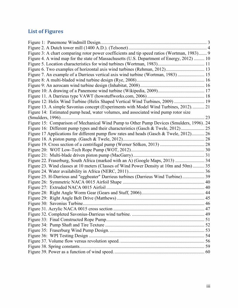
could cause turbulence, which could reduce the overall effectiveness of the wind turbine. Figure
5 shows different wind turbine site location characteristics.
Figure 5. Location characteristics for wind turbines (Wortman, 1983)
Placing a wind turbine on a hill or in a canyon will serve to enhance the amount of wind power
available, which in turn will produce more energy (Wortman, 1983). This phenomenon was
implemented in the San Gorgonio Pass, near Palm Springs, California. In order to increase the
amount of wind power generated, thousands of turbines were placed on a plateau in between two
mountains. The wind flow between the mountains was much higher than in the surrounding area.
This higher wind speed, in turn, helped generate more power (Wortman, 1983). These types of
considerations are more relevant when considering a turbine in the third world – a turbine built

12
there would need to be built with limited resources and would likely not be tall enough to avoid
turbulent wind currents that can be generated near the ground.
Wind Turbines and Machinery
Wind turbines are mechanical devices that convert wind energy into electrical or
mechanical energy (Paraschivoiu, 2002). Wind is used to turn the blades, which in turn, are used
to generate energy. This energy can either be harnessed as mechanical energy (by using the
turning shaft to pump water, for example) or as electrical energy by attaching the shaft to a
generator, which can power a device or be used or stored in a battery to be used later.
Categories of Wind Turbines
There are two distinct types of wind turbines, which are based on the orientation of the
turbine axis. The first is the horizontal axis wind turbine (HAWT), as seen in Figure 6. This type
of turbine uses a horizontal axis to suspend large rotor blades, which are turned by the wind.
HAWTs are either upwind, where the blades are on the upwind side of the tower, or downwind,
where the blades are on the downwind side of the tower.

13
Horizontal Axis Wind Turbines (HAWTs)
Figure 6. Two examples of horizontal axis wind turbines (Rehman, 2012)
A HAWT relies heavily on the direction of the wind to function. For both upwind and
downwind turbines, the rotors should be perpendicular to the wind direction for maximum wind
exposure. This is accomplished by rotating the turbine so that it faces the wind, using a motor
contained within the nacelle. In fact, a wind turbine with a fixed orientation will catch only 21
percent of the wind energy that a turbine that rotates freely would capture (Wortman, 1983). In
upwind turbines, this turbine rotation is accomplished by using a vane to measure the wind
direction, which communicates the information to a yaw drive. This yaw drive rotates the turbine
so that the turbine is facing the wind to ensure maximum power generation. A downwind turbine
does not use a yaw drive; the wind itself optimally orients the turbine. Because the blades are on
the downwind side of the tower, they act as a sail: they catch the wind and rotate to follow the
wind direction (Patel, 2006). A downwind turbine experiences a phenomenon called “wind
shade,” where the wind flow is obstructed by an object; in this case, the tower itself. This can
lead to a decrease in wind flow through the blades, which will in turn decrease the amount of

14
power generated by the blades. However, downwind turbines can be built with more flexible
blades, decreasing the overall weight of the structure. Upwind turbines avoid the wind shade
problem that affects downwind turbines by having the blades on the upwind side of the tower,
collecting the energy before the wind is affected by the tower. However, this design does not
totally eliminate wind shade, as there is also wind shade in front of the tower. An upwind turbine
also uses a yaw mechanism to rotate the blade direction (by rotating the nacelle) to optimally
catch the wind. This is required because, if left unchecked, the tower could end up rotating too
many times in one direction and potentially damaging the internal equipment (Wind Power
Wiki).
The operational speed of most wind turbines is not nearly fast enough to generate
electricity for most conventional generators. In order to reach the required speed (usually from
1200 to 1800 revolutions per minute) the turbine must have a mechanism to convert the slower
rotation of the low speed shaft (used for the horizontal turbine axis) to a faster rotation (for use in
the generator) through the use of a gearbox, located at the top of the turbine tower in the nacelle.
The nacelle encloses the low speed shaft, the high speed shaft, the gearbox, and the generator.
This enclosure sits atop the tower, behind the rotors, and serves to weatherproof the important
electrical components.
Vertical Axis Wind Turbines (VAWTs)
A VAWT, unlike a HAWT, does not rely on the direction of the wind to generate power.
It relies on a system of blades which lie on a vertical axis and are rotated by the wind, as shown
below.

15
3
Figure 7. An example of a Darrieus vertical axis wind turbine (Wortman, 1983)
Types of Wind Turbines
There are many different types of wind turbines, each with their own advantages and
disadvantages. Many of these different wind turbine designs were researched in order to better
understand them and choose one that fit with the proposal of pumping water for a village in a
third-world country.
Traditional Windmill
A traditional windmill operates at low speed and produces high torque. It is generally
used to produce mechanical power. This design has also been around for many decades allowing
for many design advancements and a large data base (Rye, 2008).

16
Figure 8: A multi-bladed wind turbine design (Rye, 2008)
Aerocam
An aerocam is a HAWT that uses multiple aerodynamic blades which cut a profile in the
air that is similar to a water wheel. This also allows it to follow the path of the wind as the blades
rotate, which means it requires no mechanical yaw correction. This wind turbine is used for
electricity production. One disadvantage of this type of wind turbine is that it is stationary,
meaning that it is only one-directional (Inhabitat, 2008).
Figure 9: An aerocam wind turbine design (Inhabitat, 2008)

17
Panemone
A Panemone windmill is a vertical-axis wind turbine. The rotating axis is positioned
vertically and the blades move parallel to the wind to catch the wind. The Panemone primarily
uses drag force to turn the blades. Wind moves the vanes of a Panemone in a circle to make the
drive shaft turn. However, a disadvantage to the Panemone is that it is one of the least efficient
types of wind turbines because the wind panels generate no work when returning to the part of
the turbine that is upwind (A Panemone (Drag-Type Windmill), 2003)
Figure 10: A drawing of a Panemone wind turbine (Wikipedia, 2009)
Darrieus Turbine
Another prominent type of VAWT is the Darrieus turbine. A Darrieus turbine uses thin
blades to capture and convert wind energy into mechanical or electrical energy.

18
Figure 11. A Darrieus type VAWT (howstuffworks.com, 2006)
The Darrieus type relies on two or more curved blades that rely on wind to revolve around a
central column (howstuffworks.com, 2006).
Savonius Rotor
One of the more prevalent types of VAWTs is the Savonius Rotor. The Savonius rotor is
less powerful than most HAWTs, and it has a high power to weight ratio. However, the Savonius
rotor is particularly useful for situations that do not require a large amount of electric power
(Paraschivoiu, 2002). Also, because of the simple design of the Savonius, it is relatively simple
to build.
Hybrid Savonius-Darrieus
A turbine design consisting of both a Savonius and a Darrieus wind turbine joins both
turbines together in order to gain advantages from each. The advantages of each of the turbines
help offset the disadvantages of the other turbine. Combining these two wind turbines results in a
turbine that is able to start itself, operate in low wind speed, and produce a high enough
efficiency to be able to transfer wind energy over to electrical power (Letcher, 2010)

19
Helix Turbine
A helix wind turbine uses long blade scoops that are helically shaped to catch the wind
from any direction. The helix is similar to the Savonius since it uses drag forces provided by the
wind and is self-starting. This is one of the more innovative designs that manipulate the
direction of the wind through its blades to increase its rotational velocity (Helix Shaped Vertical
Wind Turbines, 2009). An example of this design is provided in Figure 12.
Figure 12: Helix Wind Turbine (Helix Shaped Vertical Wind Turbines, 2009)
Wind Turbine Comparisons
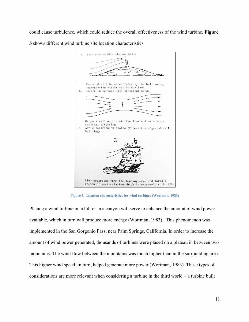
For the many wind turbines introduced previously, Table 1 compares some of the desired
characteristics important to this project. Speed, torque, and the power coefficient are important
factors to take into consideration as they help determine the performance of the wind turbine.
The wind device torque is needed to predict the turbine’s compatibility with its intended
application. Different characteristics are more relevant for different applications.
20
Table 1: Wind Turbine comparisons
Type Speed Torque Cp
(rotor
efficiency)
Lift or
Drag
Use
Multi Blade Low High 0.25-.4 Both Mechanical
Power
Three
Bladed aero
foil
High Low Up to 0.45 Both Electricity
production
Aerocam Very Low
– Low
High 0.48 Lift Electricity
production
Panemone Low Medium Less than
0.1
Drag Mechanical
Power
Darrieus Moderate Very low 0.25-0.35 Lift Electricity
production
Savonius Low High 0.1-0.2 (max
~0.3)
Drag Water pumping,
Grinding grain
Combined
Savonius and
Darrieus
Low –
Moderate
High 0.25-0.35 Both Mechanical
Power/ Electricity
production
Helix Low High N/A N/A Electricity
production
Darrieus Turbine
Because it is a VAWT, the Darrieus turbine has certain advantages over a standard
HAWT. Most HAWTs require some sort of yaw control mechanism to ensure that that turbine is
oriented appropriately with respect to the wind. Because the Darrieus turbine does not rely on
wind direction, it avoids this problem entirely. The Darrieus turbine is also typically designed to
keep the heavy machinery at ground level, reducing the total weight of the vertical section
(Paraschivoiu, 2002). However, this type of turbine is not self-starting.
The Darrieus turbine, in its most general sense, works by generating lift using the rotating
motion of the blades. Essentially, most of the “apparent wind” is coming from the air pressing on
the blade due to the rotation, and not from the wind itself. The ambient wind on the blade
creates a rearward change in momentum, and it is this that propels the blade in the direction of
rotation. This phenomenon does not occur unless the blades are already rotating, however. This
is why a separate means of starting is requires for the Darrieus turbine (OtherPower).

21
A simpler type of Darrieus, known as the H-Darrieus turbine, does not utilize curved
blades to move, making it easier to design and manufacture. Instead, it uses a number of straight
airfoils (usually two or three) to generate the requisite lift. The Darrieus is known for having
very low torque (Table 1), though its size can be manipulated to provide sufficient torque for
different applications.
Savonius Rotor
Another of the more prevalent types of VAWTs is the Savonius rotor. The Savonius
rotor is less powerful than most HAWTs, as it uses drag to rotate itself, and it has a low weight to
unit power ratio. However, the Savonius rotor is particularly useful for situations that do not
require a large amount of power (Paraschivoiu, 2002).
Figure 13. A simple Savonius concept (Experiments with Model Wind Turbines, 2012).
A simple Savonius rotor can be manufactured by cutting an oil barrel in half, inverting one of the
halves, and welding the two pieces together in an S-shaped cross-section.” The Savonius rotor is
easily constructed using little technology.
The Savonius cups can also be offset slightly, as seen in Figure 13 . This causes the
wind to flow through the center gap. This gap flow affects the performance of the rotor. A study

22
was performed that compared the performance of the turbine with the overlap coefficient of the
blades to determine the ideal ratio. It was determined that the optimal overlap ratio was 0.242
(Menet & Bourabaa). This shows that it is not optimal for the blades to be joined at the edge.
The Savonius turbine relies only on drag to turn. As such, the total turning torque of the
mechanism can be approximated by considering the drag force on the “cups” to be applied
directly on the middle of each cup. This can be seen here:
The drag force on a surface can be evaluated as:
(5)
Where ρ is the wind density, A is the cross sectional area, vwind is the wind velocity, and Cd is the
coefficient of drag on the surface. For a concave semicircle, the drag coefficient is 2.3, and for a
convex semicircle, the drag coefficient is 1.2.
Basic Water Pumping Theory
Many view wind pumping as an underutilized resource for supplying water; however,
numerous developing nations have begun to utilize its advantages. (Smulders, 1996). As seen in
Figure 14, wind pumps can be useful to supply water for a community, for one home, for cattle,
or other uses. The uses provided happen to be ideal purposes for a wind pump due to the small
head and low wind power needed, some sufficiently working with a wind speed of as little as 3
Vwind

23
meters per second (Smulders, 1996). The following figure displays different pump requirements
for different pumping applications.
Figure 14: Estimated pump head, water volumes, and associated wind pump rotor size (Smulders, 1996)
Mechanical wind pumps are ideal for required water quantities in the range from 40 to
3000 m4/day, as seen in Figure 15. For low flows, a simple hand pump could be used. However,
higher volume flow requires either a solar pump, diesel pump, or electric wind pump.

24
Figure 15: Comparison of Mechanical Wind Pump to Other Pump Devices (Smulders, 1996)
There are many pump characteristics taken into account when deciding the size and style of the
ideal pump. Although there are many different types of pumps, general pump theory can be
drawn from the Bernoulli energy equation with head loss, shown here:
(6)
Where hf is the frictional work done per unit weight. This term is usually referred to as head loss
(Subramanian). The gravitational constant, denoted by g, is 9.81 meters per second squared, p is
the pressure, h is the height, ρ is the density of the water, V1 and V2 are the respective velocities,
and z1 and z2 are the respective lengths. The head of a pump can be simply expressed as “the
height to which a fluid may be lifted by the pump in a frictionless piping system (Morrison F. ,
1999)” and can be used to compare the effectiveness of different pump designs.
Water Pump Comparisons
Different types of applications require different types of pumps, and each different pump
has different characteristics. Below is a figure showing different types of pumps and certain
attributes for each.

25
Figure 16: Different pump types and their characteristics (Gasch & Twele, 2012)
This chart compares many different pump options on the basis of appropriate head size,
head versus flow rate characteristics, and efficiency. The three pumps that were considered for
this application were the piston pump, the multistage centrifugal pump, and the chain pump (also
known as the rope pump).
Figure 17 shows several flow rate and head requirements for different applications. Each
of these pumps has different characteristics, making them suited for different characteristics.

26
Figure 17 Applications for different pump flow rates and heads (Gasch & Twele, 2012)
In order to construct a pump that will be able to supply a community with drinking water, for
example, pumping from the ground, the pump should have a low flow rate and a head ideally
greater than 20 meters. For wind pumps, a high head can be generated by the low rotational
speed that wind turbines deliver (Gasch & Twele, 2012). After selecting the application, the next
step is determining the type of pump to use.
Other than high efficiency and head size compatibility, some of the other major factors
that are ideal in a pump for this project’s purposes include little wear by non-purified water
contents, low starting torque to match the wind-turbine, little maintenance, small oscillating
forces, and relative simplicity to other pump options. Table 2 further compares the three largest
head-providing pump options on these characteristics.

27
Table 2: Pump Type Pros and Cons (Gasch & Twele, 2012)
Pump Pros Cons Notes
Pis
ton
pu
mp
For low rotational speeds, a high
total head is delivered
Has been successfully applied to
many different types of wind
pump systems
Starting characteristics can be
improved by design measures
High wear when pumping dirty water
High starting torque required
High dynamic forces due to oscillating
piston
H-Q characteristics show
that total head is ideally
independent of flow rate
Mu
ltis
tag
e
Cen
trif
ug
al
Can be used to transmit electrical
power
Not sensitive to dirty water
Low starting torque
Turbines and centrifugal pumps
are both rotodynamic machines
Difficult to manufacture if the
impellers are small
Has only been applied to
wind pump systems with an
electric coupling and a
submersible motor
Head increases with more
stages
Ro
pe
pu
mp
Can lift water up to the required
30 meters
Mechanically simple to build and
repair
Very inefficient
Can be somewhat unreliable
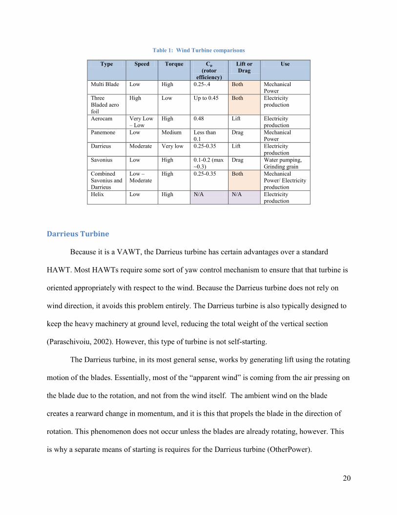
Piston Pump
Piston Pumps are the most commonly used pump option for wind pumps, currently
utilized in thousands of wind pumps on the market. Though the piston pump has some faults,
this pump is a fairly straightforward pump to construct, moves at low rotational speeds and is
often used for lifting water small distances. The piston pump, denoted as A in Figure 17, is
suitable for use in boreholes since its exterior design is slim and compact. Some experts believe
this reciprocating pump is the most important way of displacing water since the total measured
head is not variable to the desired flow rate and can function at low rotational speeds (Gasch &
Twele, 2012). Furthermore, Figure 17 provides some of the disadvantages including the high
maintenance due to wear of dirty water and the requirement of a high starting torque. A high
starting torque would require a greater power delivered from connected wind device. A cross-
section of a piston pump is shown in Figure 18.
28
Figure 18. A piston pump. (Gasch & Twele, 2012)
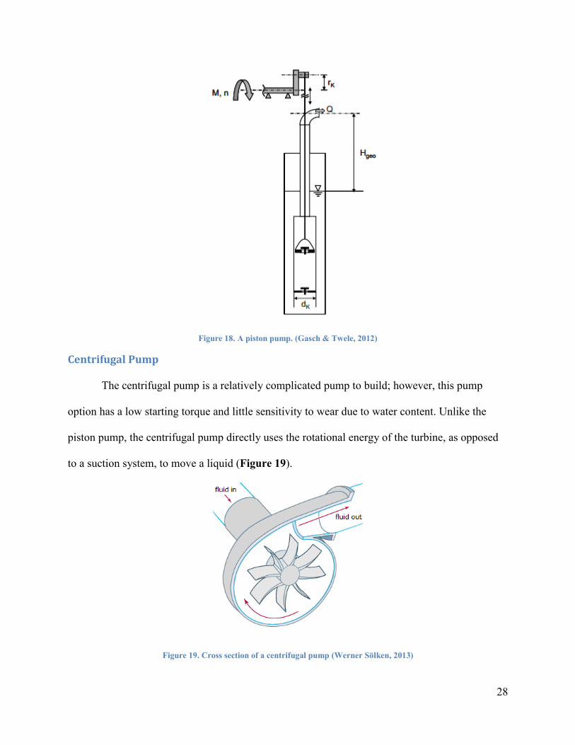
Centrifugal Pump
The centrifugal pump is a relatively complicated pump to build; however, this pump
option has a low starting torque and little sensitivity to wear due to water content. Unlike the
piston pump, the centrifugal pump directly uses the rotational energy of the turbine, as opposed
to a suction system, to move a liquid (Figure 19).
Figure 19. Cross section of a centrifugal pump (Werner Sölken, 2013)

29
The liquid flows into the center of the pump, where the rotating motion of the impeller is
used to push the liquid out from the center, where it flows through the outlet. The pump impeller
requires a high rotational speed to move the water. This means that the rotational torque provided
by the turbine can be almost directly applied to the pump impeller.
Rope Pump
Another pump type that was discussed in Figure 16 is the rope pump. This pump is one
that can be easily operated and maintained in a third-world setting. As shown in Figure 20, the
rope pump is a device that rotates a rope around a wheel down to the water source and up
through a pipe. The water can be drawn up from wells or boreholes. There are small metal,
rubber, or plastic discs with less than one millimeter clearance of the pipe which are attached to
the rope and act as pistons to draw water through the pipe. The pipe ends at the water surface
where there is a faucet type outlet that releases the water as the rope continues to circle around
the wheel. No efficiency was found in the literature, but it is expected to be low, resulting in low
flow rates. The expected flow rate is around 40 liters per minute from a depth of 10 meters. The
pump can be used by single families or up to 20 families, approximately 100 people (Akvopedia,
2012.)
Rope pumps are being used in over 30 countries worldwide as of 2008. Some of these
countries are Nicaragua, Zimbabwe, and Ghana. In Nicaragua, they had previously been using
piston pumps. The switch to rope pumps has saved a lot of money annually and has doubled the
rural water supply in ten years (Akvopedia, 2012.)

30
Figure 20: WOT Low-Tech Rope Pump (WOT, 2012)
Current Wind Pump Designs
Current wind pumps are most commonly found on farms and ranches in North America,
Africa, and Australia. Farms and other large, open areas that are disconnected from electrical
services can largely benefit from wind pumps due to their free wind-driven power, durability,
and minimal maintenance (LILI, 2012). As described earlier, wind pump machines are not a
new concept, dating back to the 19th
century. One example is the American farm wind pump
which was a common wind pump used to deliver large amounts of water for agriculture
purposes. This wind pump usually has a multi-bladed rotor and is made almost entirely from
steel. The rotor is connected to drive a reciprocating pump, generally a piston pump, by way of
reduction gearing (Wind Power, 2007). Since its first appearance, the multi-blade piston pump

31
has made many advancements and, today, is the most common mechanical wind pump on the
market (Figure 21) (Practical Action, 2013).
Figure 21: Multi-blade driven piston pump (MacGarry)
Two major innovations on this design include the engineering of a counterbalance for the
weight of the rod and the development of variable strokes. Another is the use of 6 to 8 blades of
true airfoils, as opposed to traditional windmills, which use 15-18 curved steel plates. These
newer generations of wind pumps use direct drive mechanism instead of a geared transmission.
The direct drive mechanism helps produce high torque at low wind speeds and control rotor
speed at high wind speeds (Argaw, 2003).

32
Other wind pumps on the market include various battery-connected wind turbines that
electrically power pumps. Companies such as TF, Depon, and Dahai manufacture electrically
driven wind pumps costing as much as $3000 USD (Alibaba, 2013). Other alternatives of
pumping mechanisms include hand pumps and solar driven pumps. Though these are not wind-
powered, they give additional insight into the sustainably-powered pump market. The hand
pump functions mechanically, and is easily installed; however, requires the physical power and
time of community members. The solar-driven pump is electrically powered and is very
complex to reproduce (Alibaba, 2013).

33
Chapter 3: Design
The goal of this project was to design, construct, and test a wind driven water pump that
is suitable to provide fresh water to a community in a third world country facing difficulty
accessing water. The design takes into consideration ease and simplicity of construction,
implementation, and repair, as well as cost and availability of materials.
Location Selection and Specifications
In order to determine an appropriate location for the wind pump, one must consider
certain factors. First and foremost, the wind pump is designed for implementation in a third
world country using available materials and tools. This limits the design by imposing restrictions
on the types of materials. It can be assumed that the majority of readily available materials in the
country of South Africa include resources such as wood, scrap metal, bricks, concrete, and old
tires. Many more modern technological advances are not easily obtainable there; therefore,
certain materials might have to be bought elsewhere. However, a major design goal for this
system was to use materials that could be obtained in South Africa in order to allow the wind
pump to be constructed there.
Using these types of materials, it would not be realistic to build a turbine with a height of
anywhere near 50 to 100 meters. However, the height of the turbine must be high enough to
allow the turbine to catch the wind above any major turbulence generated by trees or buildings
near the ground.

34
Figure 22. Fraserburg, South Africa (marked with an A) (Google Maps, 2013)
Second, the wind pump must be built at a site that has suitable wind and water resources. This
site should also be located close to an existing village, so that the village is able to access the
pumped water. Additionally, the wind speed at this location must be consistently high enough to
power the turbine. The wind speeds in Fraserburg for the week of April 20th
through the 27th
,
2012, are shown in Table 3.
Table 3. Wind speeds for Fraserburg, South Africa
Wind Speed for Fraserburg, South Africa (in knots)
Friday Saturday Sunday Monday Tuesday Wednesday Thursday Friday
5 6 6 14 11 9 4 5
4 6 7 13 11 7 7 5
4 7 10 15 13 5 8 7
5 14 11 16 12 13 12 19
15 15 12 16 13 16 12 22
16 14 13 16 12 15 12 19
9 9 15 13 10 10 8 12
7 5 15 12 9 5 6
Averages (knots)
8.125 9.5 11.125 14.375 11.375 10 8.625 12.71429
Total Average (knots) Total Average (m/s)
12.26 6.31

35
The total average wind speed for the week is 6.3 meters per second. According to the
National Renewable Energy Laboratory, a wind speed of 6.3 meters per second falls into Wind
Class 5, rated “Excellent” for wind power production.
Figure 23. Wind classes at 10 meters (Classes of Wind Power Density at 10m and 50m)
Obviously, further investigations would need to be made regarding the wind speed over
the course of an entire year, but this provides a good estimate for a reasonable average wind
speed for the region. Wind direction can also be a factor in site selection. If the wind only
naturally flows in one direction (in a canyon, for example) then the turbine does not have to
change direction based on the wind direction. However, many sites have wind that comes from
different directions; in this case, a VAWT (which does not generally rely on wind direction to
generate power) could be more useful than a HAWT.
Third, the water well must be able to provide for a community of 500 people. Since the
goal is to provide clean drinking water to a small village in South Africa, Figure 14 shows that
for a “Community water supply,” a village of 500 people would require a daily volume of 20

36
cubic meters per day, or about 0.23 liters per second. A map of general water availability in
Africa is shown in Figure 24 as well as the general location of Fraserburg marked with a black
arrow.
Figure 24. Water availability in Africa (NERC, 2011)
As the figure shows, the area that Fraserburg is located in has a low to low-moderate
potential for pumping water (from 0.1 liter per second to 1 liter per second). If the requirement

37
for drinking water for 500 people is 0.23 liters per second, then it should not be difficult to find a
location with an adequate water supply.
The overall minimum requirements for a wind pump location involve a combination of
wind speed and water availability, as well as proximity to an existing village. Specifically, the
water availability of the site must exceed 0.23 liters per second in order to adequately provide
water to a hypothetical village of 500 people. Additionally, the wind should be at least Wind
Class 4 (“Good”, as seen in Figure 23) in order to provide adequate wind power to turn the
turbine, and the site should be relatively clear of trees, buildings, and other significant
obstructions. Finally, the site should be close enough to an existing village to facilitate water
transportation.
Wind Turbine Selection and Design
The first step in deciding on a wind turbine design was determining the importance of
certain characteristics and comparing these features of different turbine design options. From the
background research, the design options were narrowed down to four: a multi-blade, a Savonius,
a Darrieus, and a combined Savonius/Darrieus. By weighing the importance of certain features,
the wind turbine most fitting for this project’s purpose was selected. The different turbine
features analyzed were the ease of construction in a third world country, the power output, the
expected power output during operation, starting torque characteristics (as well as whether it
self-starts or not), and the overall efficiency of the device. The design matrix used can be seen in
Table 4.

38
Table 4: Turbine Design Matrix
Design Matrix Multi-blade Savonius Darrieus Combined
Savonius/
Darrieus
Feasibility in a
Third world
Country (50)
.8
40
.7
35
.4
20
.6
30
Power Output
During
Operation (25)
.2
5
.2
5
.6
15
.7
17.5
Self-Starting/
Starting Torque
(20)
.7
14
.8
16
.4
8
.7
14
Estimated
Efficiency (35)
.3
10.5
.2
7
.7
24.5
.8
28
Total 69.5 63 67.5 89.5
The multi-blade turbine (using a design close to a standard HAWT, but using flat blades
instead of airfoil shape blades) performs well in both the third world feasibility category and the
self-starting category. Both the Darrieus and Savonius turbines, by themselves, have advantages
and disadvantages. The Savonius is simple and easy to construct in a third world and has good
torque characteristics, but it has a very low efficiency and provides a low relative torque
compared to the other designs. Where the Savonius did well, the Darrieus did not, however. The
Darrieus is not able to start itself, and has a complicated design, especially for a third world
country. However, it has a better efficiency and can provide the necessary torque for the pump to
run. Due to the differences in characteristics between the Savonius and Darrieus turbines, the
combined Savonius-Darrieus turbine has some significant advantages over both. It combines the
relative strengths of both without succumbing to the weaknesses that both turbines have. The

39
combined Savonius/Darrieus turbine was chosen due to its relatively high efficiency, ease of
construction (in the case of an H-Darrieus), and ability to self-start.
Design of Darrieus Turbine
The design of a standard Darrieus turbine is relatively complex, especially when
compared to other wind turbine types that were considered. In order to simplify the design, a
particular type of Darrieus turbine was used called an H-Darrieus. Instead of using a more
complicated, curved blade shape, the blades of an H-Darrieus are straight, making the design and
construction of the blades much easier. A comparison between H-Darrieus and normal
“eggbeater” Darrieus are shown below in Figure 25.
Figure 25. H-Darrieus and "eggbeater" Darrieus turbines (Darrieus Wind Turbine)
By using a straight blade, the work required to shape the blade is significantly decreased; one
could hypothetically create a blade using a single piece of material without needing to bend it.
The shape of the blade used for the H-Darrieus is a NACA 0015 airfoil. This type of airfoil is

40
very common, especially among hand constructed (so-called “backyard”) Darrieus turbines.
Using this airfoil as the blade for a Darrieus turbine generates a net forward force on the blade,
which then moves the H-frame around, generating torque on the center shaft. This shaft is then
connected to something which utilizes the rotational energy; in this case, a water pump.
Figure 26: Symmetric NACA 0015 Airfoil Shape
Figure 27: Extruded NACA 0015 Airfoil
The design of the Darrieus turbine needed to meet three goals. First, the turbine needs to
provide enough torque to power the water pump at an expected average wind speed. Second, the
turbine should be able to withstand normal operating forces without mechanically failing. Third,
the design should be simple enough to build and maintain in rural South Africa.
Design of Savonius Turbine
The use of the Savonius turbine is to assist the Darrieus turbine. The Darrieus turbine
converts the linear motion of the wind into rotational motion that the turbine can use. However,
the Darrieus requires an initial rotational speed to move in this manner, because the blades

41
require motion to generate lift. In order to solve this problem, a pair of Savonius turbines was
added to the top of the turbine frame. These two turbines will provide the self-starting capability
that the mechanism requires. In order to overcome any force, the Savonius was sized so that it
was able to start the combined turbine without any help from the Darrieus.
The method used for sizing the Darrieus turbine involved estimating the power required
to move the pump. This information could then be used to calculate an approximate size for the
Darrieus using the power equation, seen above in Equation 3.
In order to improve the performance of the Savonius turbine, there are a few different
options. First, increasing the surface area of the Savonius will allow the turbine to capture more
wind, which results in more force acting on the shaft. Second, mounting the Savonius turbine
cups further from the central shaft will create a longer radius for the force to act on, which
generates more torque on the shaft. Third, reducing the required torque to the shaft would
increase the effectiveness of the Savonius without needing to change the size of the turbine. This
could be done by reducing the necessary torque. However, because of the specific requirements
for the pump-turbine system, this is not a viable option.
The Savonius-Darrieus is normally used as an electric power source storing energy in a
battery. In this case, the starting torque can be achieved with the Savonius turbine directly
attached to the shaft, without arm offset. Due to the mechanical decision of this project, the new
Savonius design is offset 0.149 meters in each direction to generate more torque. The additional
torque is needed to overcome the friction and weight of the water being initially drawn through
the pump. Some basic design calculations are located in Appendix C.

42
Pump Selection and Design
To determine the most appropriate pump design, a design matrix was based off of the
background research and performed on three pump options: the piston pump, the rope pump, and
the multistage centrifugal pump. The importance of each desired characteristic was weighed to
determine which pump design was most appropriate.
Table 5: Pump Design Matrix
Important Design
Characteristics Piston Pump Rope Pump
Multistage
Centrifugal
Simple Construction
30 points
.5
15
.9
27
.25
7.5
Available Materials
10 points
.75
7.5
.95
9.5
.4
4
Inexpensive Materials
20 points
.7
14
.85
17
.4
8
Total Head (30 meters)
20 points
.75
15
.9
18
.75
15
Wind Device Connection
20 points
.7
14
.5
10
1
20
Total 65.5 81.5 54.5
Before considering the specific needs of the third world device, the centrifugal pump was
the most compelling choice. The rotation motion of the centrifugal pump matched up well with
the wind turbine’s turning shaft. However, in the process of trying to design and construct a
possible centrifugal pump, the pump design was very complex and not easily constructed with

43
low end materials. Appendix C shows some of the detailed calculations towards use of the
multi-stage centrifugal pump.
The most difficult aspect of a piston pump is the placement of the piston itself. The
piston would have needed to be within ten meters of the water source to work at an acceptable
pressure as shown by rearranging a well-versed pressure equation. Using atmospheric pressure
(P) and the density of water at sea level (ρ), the maximum possible head can be demonstrated as:
(
⁄ ) ( ⁄ )
This caused issues because the piston shaft would have needed to be at least 20 meters long,
working in both compression and tension. A shaft this long would be very heavy to lift and
would be more likely to buckle under the required loads.
The ultimate choice for this project is the rope pump, due to its favorable head
characteristics and ease of design and construction. Rope pumps are very easy to reproduce, can
be made out of available materials, and require low maintenance (WOT, 2012). Additionally,
rope pumps can lift water approximately 35 meters, and would only require a right angle belt
drive or gearbox to connect this pump to the wind shaft. The rope pump is a design not often
used. Though its simplicity, affordability, and high head are great advantages, its inefficiencies
may deter many, but its minimal use generates a great lack of awareness. The few cases that
rope pumps are used, they are built to be driven manually. This design is an innovative attempt
to match a rope pump with a non-manual mechanical driving force.

44
Connecting the Turbine and the Pump
For this design, the turbine rotates vertically so that the shaft follows the z-axis while its
rotational velocity falls in the x-y plane. The pump rotates horizontally so that its rotational
velocity moves in the y-z plane, perpendicular to the rotational speed of the turbine. This means
that whichever connection used, the rotations need to connect at a right angle. Two options
include a gearbox power transmission and a belt drive.
Gearbox Power Transmission
The relation of the rotational speed and torque of each machine is:
(7)
Figure 28: Right Angle Worm Gear (Gears and Stuff, 2006)
Standard gearboxes are pre-made and sold by many manufacturers. Ratios such as 1:1,
1:2, 1:5, and 1:10 are easily found for parallel rotating gears as well as right angle gears (Figure
28) as in needed in this case. There are also many manufacturers who build custom gearing for
special cases. Unfortunately, the price of an inexpensive gearbox ranges from fifty dollars to
hundreds of dollars depending on the needed size and ratio. As such, the price of a gearbox is
too expensive for the purposes of this project.

45
Belt Drive Power Transmission
An alternate method of power transmission is the belt drive. Similar to gearboxes, belt
drives can be used to transmit rotational energy with a change the direction of rotation. Figure
29 shows an example of a belt drive which could be used for a wind turbine.
Figure 29: Right Angle Belt Drive (Matthews)
While most gearboxes generally have complex designs, a belt drive is simple enough to be
usable for this application. It would simply be two wheels connected by a belt which can be
twisted to achieve the desired turn angle. Additionally, the simplicity of its design makes
construction and implementation cheaper and easier. In general, however, belt drives tend to be
less reliable than standard gearboxes, resulting in a greater chance of mechanism failure during
normal operation.
For the final turbine-pump design, the belt drive was selected. The materials required to
construct a belt drive are fairly easy to find, and even if the drive fails, it is easy to repair. A
conventional gearbox would be more expensive and would require additional time and money
for routine maintenance.

46
Prototype Construction
Utilizing the design matrix, a Savonius-Darrieus Rope pump design was decided as the
final product of this project. The construction of the wind turbine was done in two separate
parts, the Savonius turbine and the Darrieus turbine, and the rope pump was mirrored after a
Dutch design for third world nations. The construction methods for these three sections are as
follows.
Savonius Turbine Construction
The base for the Savonius turbine was a 5-gallon bucket sawed in half. This method was
the easiest way to approximate the cup-shape necessary for the Savonius design. In order to affix
the cups to the center shaft, two 1 foot long aluminium shafts were attached using angle brackets,
as seen below in Figure 30.
Figure 30: Savonius Turbine
Savonius Turbines

47
In order to affix the arms securely to the turbine, holes were drilled in the arms and angle
brackets were attached with bolts. These bolts made it easier to attach and remove the arms
because they were not permanently attached. This modular setup made it easier to store the
components during construction and transportation. Because the thickness of the plastic sides of
the buckets were too thin, they were reinforced on each side with ½ inch thick plywood to give
the nail something to grip instead of the plastic. This method proved to be very effective in
keeping the arms securely attached to the turbine.
Overall, the construction of the Savonius turbine was fairly simple and straightforward,
which fit with the goal of this project. It should be easy to reproduce this design with limited
third world technology.
Darrieus Turbine Construction
The construction of the Darrieus turbine was somewhat more complex, due to the precise
nature of airfoil construction. The final airfoils were constructed using insulating foam covered
in a layer of fiberglass, to ensure that the airfoils would be strong and light.
The shape of the airfoil is based on the NACA 0015 shape. This shape means that there is
zero camber to the airfoil. In order to create this shape, a cross section of the specific shape and
size of the airfoil was laser cut out of a piece of acrylic.
Figure 31. Acrylic NACA 0015 cross section
48
These cross sections were carefully attached to an 8 inch wide block of foam and cut with a hot
wire cutter. This created an 8 inch section of NACA 0015 airfoil. However, the airfoils needed to
be 2 feet long, so three sections were cut and glued together end to end.
In order to prepare the fiberglass, the fiberglass mesh was cut into a size equal to the
surface area of the airfoil, with a ¼ inch excess on each side. A section of peel ply was also cut
to the same size. Next, the fiberglass resin and the fiberglass hardener were mixed. Once the
resin and the hardener were mixed, they needed to be applied quickly or the mixture will harden.
A layer of the mixture was applied to the surface of the foam airfoil, after which the layer of
fiberglass mesh was applied. All of the air bubbles were removed from the mesh and some more
of the resin was applied. In order to soak up the excess resin, a layer of peel ply was wrapped
around the outside. This had the added advantage of creating a smooth, uniform outer layer that
could be safely placed on a surface to dry. The entire airfoil was placed in a vacuum bag, which
prevented air bubbles from forming during the drying process, and left overnight to dry. Once
finished, the excess fiberglass was cut off using a bandsaw and the airfoils were ready to be used.
The airfoils were attached to the center shaft using a technique similar to the one used for
the Savonius. Angle brackets were attached to both the shaft and airfoils, and connected by a 1
foot aluminium rod. Bolts were used to connect the angle brackets to make it easier to quickly
remove the aluminium rods for transportation and storage.
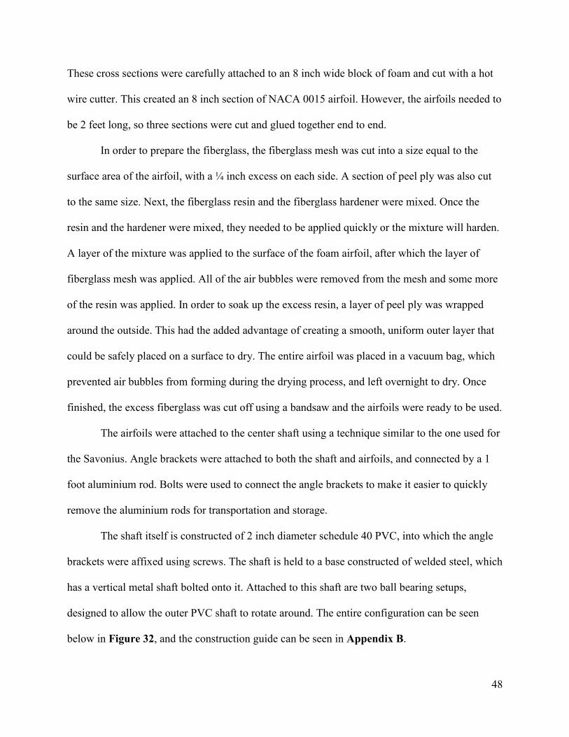
The shaft itself is constructed of 2 inch diameter schedule 40 PVC, into which the angle
brackets were affixed using screws. The shaft is held to a base constructed of welded steel, which
has a vertical metal shaft bolted onto it. Attached to this shaft are two ball bearing setups,
designed to allow the outer PVC shaft to rotate around. The entire configuration can be seen
below in Figure 32, and the construction guide can be seen in Appendix B.

49
Figure 32. Completed Savonius-Darrieus wind turbine.
Airfoils
First considering the Darrieus, due to its light weight and durability, a design decision
was made to create the Darrieus airfoil wings from fiberglass. Fiberglass is easily molded into
any desired shape while maintaining a light load and drying into a robust material. The shape of
the airfoil was made from Styrofoam insulation using a hot wire cutter. To make certain the
shape of the airfoil was cut correctly, a thin cross-section of the airfoil was created in
SolidWorks and then laser cut out of acrylic material. This shape was attached to either end of 6
inch by 4 inch foam insulation sections. The hot wire cutter was pulled along the NACA 0015
airfoil shapes until a 8 inch section of the 2 foot airfoil was successfully outlined. Each airfoil
consisted of three 8 inch sections glued together and carefully sanded before the fiberglassing
process took place. The fiberglass material was in the form of a flexible, white fabric. Prior to
mixing the epoxy chemicals, the fiberglass fabric was cut to cover the entire 2 foot airfoil foam
with an overhang of ¼ inch extra fabric. After protecting the work area with plastic, the two

50
chemicals of the epoxy were mixed, five parts resin and one part hardener. The epoxy needed to
be used within five minutes of mixing. Carefully, the epoxy was spread over the foam with a
roller to act as an adhesive for the fiberglass fabric. The fiberglass was then immediately applied
over the shape of the airfoil and all air bubbles were brushed out any of the open ends away from
the rounded airfoil edge. The wet, fiberglassed airfoil was then left to dry for approximately 24
hours. After the 24 hour drying time period, the excess ¼ inch fiberglass material was carefully
cut from the edges leaving a 2 foot NACA 0015 airfoil.
Rope Pump Construction
The rope pump design for this project was based on a document created by a Dutch
organization, WOT, which focuses on construction of a low-tech water and energy mechanisms
for developing nations (WOT, 2012). Some design modifications were made to yield better
lubricated connections as well as weight considerations so that the final design is relatively light
and portable. For ease of construction and to keep cost low, most of the rope pump was created
out of PVC pipe. PVC is a type of plastic with a friction coefficient of 0.2 when dry and as low
as 0.04 when lubricated and functions with high strengths in tension and wear. In tensile
strength, PVC can take loads up to 62 megapascals and a bending strength between 69 and 114
megapascals. This material is strong, lightweight, and inexpensive. Additionally, PVC is
conveniently found at most commercial building stores since it is the most widely used
municipal water supply and sewage material (PVC, 2013).

51
Figure 33: Final Constructed Rope Pump
For this project, PVC was used for the rotating shaft to support the wheel, the frame to
hold the wheel shaft and pipe, as well as the pipe to draw the water from the water source
(Figure 33). The wheel was made from a spare tire as in the guide. The benefits of using a tire
are due to its high friction coefficient (up to 0.9) as well as the small rubber fins protruding from
its surface. The high friction coefficient and gripping fins are used to pull the rope and pistons
upward through the pipe and faucet as the tire spins (Figure 34). Most ropes with high tension
properties can be used for this pump; however, the rope needs to be thin enough to tie knots on
either side of the discs and not exceed the disc’s diameter. For the ½ inch PVC pipe, 1/4M
washers were used as pistons to provide minimum clearance; however, the piston discs can be
made from metal, plastic, or even excess rubber from the wheel.

52
Figure 34: Pump Shaft and Tire Texture
The water is lifted through the pipe by the discs and deposited in a reservoir. Due to the nature
of the design, there is no pressure generated by the pump; the weight of the water directly
opposes the lifting force generated by the rope pump. Even though the design condition calls for
the water to be lifted from 35 feet underground, the narrow pipe diameter means that the weight
of the water is fairly low. However, due to the low-tech nature of the pump, there are significant
losses due to friction and leaking. A complete rope-pump construction guide is provided in
Appendix B-2.
Idealized Final Design for Fraserburg, South Africa
Figure 35 displays the desired layout for a Savonius-Darrieus wind pump to be
implemented in Fraserburg, South Africa. The combined Savonius-Darrieus wind turbine is
elevated to a height of 10 meters in an area with favorable wind characteristics. The turbine will
turn the rope pump, which will lift drinking water from deep underground. The lifting force is
generated by rotating the wheel using the wind turbine. The axle is attached by belt drive to the
rotating shaft which is turned by the turbine. The overall structure will be lightweight,
inexpensive, and easy to maintain in a third world country.

53
Figure 35: Fraserburg Wind Pump Design.
Due to certain limitations on campus, this project did not have the resources to accurately
mirror the exact situation in Fraserburg, South Africa. As such, the design to be tested at WPI
will be slightly different (Figure 36).

54
Figure 36: WPI Testing Design
The size of the Darrieus blades and Savonius blades remained the same; however, the
entire structure is not as far off the ground. The WPI turbine setup was built on a 10 foot shaft
made of 2 inch PVC. Additionally, no well was utilized to test the project. During the process of
attempting to emulate the Fraserburg design, no satisfactory method was derived. Instead, the
pump was tested to make sure that the device can create a satisfactory flow through the pipe and
the amount of torque required to generate this flow was measured.
Material Availability and a Package Concept
For this project there was a large focus on the feasibility of reconstruction in a third world
country. When researching available materials, this topic was found highly dependent on the
location at hand. Many rural areas in Africa do have access to home-run wood shops, basic
tools, and scrap materials (Cole, 2008). Residents of these areas tend to be very creative in how
to construct homes, wash areas, and other facilities of need. While some areas do not have
access to developed cities in Africa, other are capable of even purchasing basic materials from

55
small construction shops selling tools, wood, nails, and other simple resources. The areas that
are less fortunate rely on NGO aid, local innovators, and available scrap (Cole, 2008).
For this project, many of the materials were based on easily obtainable resources. Items
such as the tire for the rotating shaft and buckets for the Savonius are likely to be available in
many third world areas. If buckets or tires are not available, any light weight material that can be
shaped into a semi-cylinder or other rubber material can work to cover the same functions.
Many other items for this design can be replaced with other readily available materials as well,
provided many of the characteristics remain the same. Additionally, if some of the more difficult
materials such as the shape of the Darrieus airfoil, the ball bearings for the shaft, or the fiberglass
material is not easily obtained, there is the idea to manufacture a small package in the United
States to send a smaller list of materials to areas interested in this wind-pump application. To
limit cost, the more complex aspects of this design were limited to minimize the size of the kit
that would be provided as construction aid.

56
Chapter 4: Results and Analysis
The basic requirement for the pump-turbine design was that the system provides an
adequate amount of water for a small village: 20 cubic meters of water per day. More generally,
the construction and maintenance of the wind pump needed to be possible in a third world
country. This provided a set of guidelines around which the prototype pump could be designed.
In order to increase pump volume flow for the actual model, the size of the main water pipe
would likely be increased. This would allow the pump to bring more water to the surface with
every revolution.
The pump needed to pump at least 0.231 liters per second in order to meet the minimum
defined requirements. To find the maximum pump flow rate, the pump was powered by hand at
varying speeds. A representation of the data points collected can be seen below in Figure 37.
Figure 37. Volume flow versus revolution speed.
0
0.02
0.04
0.06
0.08
0.1
0.12
0.14
0.16
0.18
0 0.2 0.4 0.6 0.8 1 1.2 1.4 1.6
Vo
lum
e f
low
rat
e (
L/s)
Revolutions per Second (rev/s)
Volume flow rate vs revolutions per second

57
It can be seen that there is a maximum flow rate that can be provided by the pump (0.156 liters
per second, corresponding to a speed of 1.18 revolutions per second). Rotating the pump any
faster resulted in leakage losses due to the design of the pump.
For the combined Savonius-Darrieus, the power generated by the turbines can be
estimated by calculating the expected torque. The Savonius turbine relies only on drag to turn.
As such, the total turning torque of the mechanism can be approximated by considering the drag
force on the “cups” to be applied directly on the middle of each cup. This can be seen here:
The drag force on a surface can be evaluated as:
Where ρ is the density of the surrounding air, A is the cross sectional area, vwind is the wind
velocity, and Cd is the coefficient of drag on the surface. For a concave semicircle, the drag
coefficient is 2.3, and for a convex semicircle, the drag coefficient is 1.2. By evaluating the
above expression using the available parameters, the net drag is evaluated as 2.9 newtons,
applied at the middle of the Savonius cup (which is the same as the radius of the Savonius
turbine). Using equation 8 above, the torque generated by the Savonius can be estimated to be
1.33 newton-meters.
Another method, which can be used for both the Savonius and Darrieus turbines, is
calculated using the following formula:
Vwind

58
(8)
With ρ as air density, vwind as wind velocity, Cp as the coefficient of power, and Acs as cross
sectional area. While useful, this equation is very general and cannot be properly calculated
without an accurate coefficient of power for the combined Savonius-Darrieus turbine.
Testing and Results
To determine the amount of power required to run the pump, the prototype pump was
built and tested in the laboratory. Once functional, a piece of string was affixed at one end and
wrapped around the shaft approximately ten times. Weights were then added to the string until
the weights were able to pull the string and rotate the shaft at a speed of 1.18 revolutions per
second. It was discovered that the weight required to turn the pump at the required speed was 14
pounds, or 62.3 newtons of force on the shaft (which has a radius of 2.4 centimeters). Using this
equation for torque:
(9)
this results in a required torque of 1.5 newton-meters on the shaft.
To determine how much torque was generated by the turbine, a rudimentary force gauge
was created using a spring affixed to the shaft with a string. The string was affixed to the shaft at
one end, and when the turbine turned in the wind, the string wrapped around the shaft and
eventually pulled the spring a certain distance, which was recorded. The force generated by the
turbine could then be calculated using the spring constant of the spring.
The spring constants of two different springs were calculated by measuring the
elongations of the weighted springs. The results of this measurement can be seen in Figure 38.

59
Figure 38. Spring constants.
The small spring was selected for use in the test, which has a spring constant of 1.27 newtons per
centimeter.
By attaching the spring to the wind turbine shaft and measuring the elongation of the
spring, the force on the spring (and therefore the torque generated by the turbine) was measured.
Using a wind speed of 5 miles an hour (or 2.23 meters per second), the spring elongation was
measured as 14.9 centimeters. This means that the turbine provided 18.92 newtons of force to the
spring. Calculating the torque using equation 9, with a turbine shaft radius of 2.4 centimeters,
results in a torque of 0.454 newton meters. This is below the required torque for the pump;
however, the wind turbine was tested using a relatively low wind speed, and wind power
increases as a function of wind velocity cubed, as seen in equation 8, which is redisplayed below
for clarity.
(8)
(10)
y = 1.2707x + 11.351
y = 2.6214x + 11.365
0
10
20
30
40
50
60
0 5 10 15 20 25 30 35
Spri
ng
Len
gth
(cm
)
Force (N)
Small Spring
Big Spring
Linear (Small Spring)
Linear (Big Spring)

60
Also printed above is an equation that expresses the power, P, as a function of torque (τ) and
rotational speed (ω). For the prototype pump, there is a specific optimal rotational speed at 1.18
revolutions per second, as stated above. For the prototype turbine, the rotational speed (and the
power) will increase as the wind speed increases, as shown in equation 8. Using this equation,
the power generated by the wind turbine can be estimated and matched to the power required by
the pump, as calculated using equation 10:
[ ] [
]
Which is displayed below in Figure 39 by a blue line. The red line is a representation of the
power from the turbine using equation 8, using a conservative estimate for the coefficient of
power (0.1). It can be seen that the two lines intersect at a wind speed of 6.46 meters per second,
just above the estimated wind speed for the region of 6.3 meters per second.
Figure 39. Power as a function of wind speed.
As stated above, the turbine is relatively inefficient at lower wind speeds. However, at the design
condition, it can be seen that the turbine should be able to provide enough power to the pump to
run it at its optimal speed.
0
5
10
15
20
25
30
35
40
45
1 2 3 4 5 6 7 8 9 10
Po
we
r [w
]
Wind speed [m/s]
Power from Pump [W]
Power from Turbine [W]

61
Cost Comparison
Since one of the major aims of this project was to mimic a wind pump feasible for
developing nations or a package that could be easily sponsored, the materials need to be fairly
inexpensive. The project budget is on a similar level of available funds. The numerous
competitive pump devices discussed earlier in the Background are compared in Table 6. As
shown, there is a wide range in options and product costs from $900 USD to $10000 USD.
Since many of the wind pumps currently on the market are electric, there is an added cost for
battery and electrical connections.
Table 6: Current costs for wind pump comparison
Company Product Electric or
Mechanical Head Price
WPI Savonius-Darrieus
Rope Pump Mechanical 30m $310
Survival Unlimited Hand Pump Mechanical 60m $900
TF Wind
Unknown pump Electric N/A $2345
Depon
Wind
S.Stage
Centrifugal
Electric 118m $2568
Dahai Wind
Piston Pump Electric N/A $3000
Most Common Multi-blade
Piston Pump Mechanical 100m $10000
Material for this table found from: Survival Unlimited, Alibaba
The most common wind pump design uses mostly steel and can cost upwards of $10000
to build and install. For comparison, a hand-driven mechanical pump is even almost $1000.
Working within a small budget, the final design for this project amounted to a total of $350
USD. The WPI prototype cost is based on the expectation that community members would
construct the device themselves and thus does not include the cost of manpower. Most of the
competitors’ pricing does include manpower costs which would still be necessary for the high-

62
technology methods for construction, however, excludes an installation charge which could add
significantly to the cost. The WPI prototype competes very well against the options on the
market and proves to be a more affordable to fit a third world country’s water needs. For
reference, the cost breakdown and parts list is included in Appendix A.
The affordability of the WPI wind pump design is due to the emphasis placed on the
simplicity of the design and the limited budget with which the group worked. Ideally, the low
cost of the turbine-pump system would make it more available to individuals or NGO’s in third
world countries.
Conclusions and Recommendations
This project concluded that a wind turbine of this size could adequately run the hand
powered water pump design that was used. However, the flow rate is inadequate compared to the
design specifications, with a final maximum flow rate of 1.55 liters per second (or 67.4% of the
design condition of 2.3 liters per second). It is believed that, due to the prototype nature of the
design, there was a significant amount of energy lost to friction and the low efficiency of the
machines. In particular, the water pump experienced significant leakage and water loss during
operation. However, even with this kind of flow rate, the pump is still effective at providing
water.
The goal of this project was to design and build a turbine-pump system that could be
constructed in a third world country. This means that the most significant design restrictions
were related to the construction methods instead of the efficiency; as such, the design goal was to
create a pump that was inexpensive rather than efficient. In that respect, the project was an
absolute success. If this project were to be continued past the current stage, the project goals

63
would likely change to focus more on the effectiveness of the turbine and the pump by
improving efficiency and reducing losses present in the current design.

64
Appendix A: Cost Breakdown
Contained here is a cost breakdown of the list of materials used for construction of the
wind turbine and pump prototype designs.
Appendix A-1: Wind-Device Materials
Part # Part Name Material Amount Price Per Total Price
1 Rotating Shaft 2” ID x 10’ PVC 1 $ 6.59 $ 6.59
2 1’ Darrieus/Savonius Arms Steel 4 x 3’ $ 5.57 $ 22.28
3 L-brackets Aluminum 8 x 4pack $ 4.12 $ 32.96
4 Airfoil Fiberglass Materials: Peel ply Fiberglass Mesh Epoxy Fiberglass Roller
Fiberglass Epoxy
1 roll 1 roll 1 1
$ 98.34 $ 98.34
5 Airfoil Shape 2’x2’x1” Insulation Styrofoam
1 $ 4.95 $ 4.95
6 Open Ball Bearing 2”OD 1”ID Steel 1 $ 11.15 $ 11.15
7 Flanged Open Ball Bearing 2”OD 1”ID
Steel 1 $ 15.08 $ 15.08
8 Fixed shaft support 1”OD x 6’ Aluminum 1 $ 13.13 $ 13.13
9 Savonius Blade Bucket Plastic 2 $ 2.60 $ 5.20
10 Bucket Lid Plastic 2 $ 1.28 $ 2.56
11 3’ H-frame bars Steel 4 x 3’ $ 5.51 $ 5.51
12 Drywall Screws 1 pack (1 lb) $ 6.47 $ 6.47
13 Machine Screw Nut 8/32” Zinc 1 pack $ 3.92 $ 3.92
14 Machine Screw 8/32x1.5” Zinc 1 pack $ 6.21 $ 6.21
15 Plywood Wood 8 x [1” x 12”] - -
16 Masking Tape Tape 1 roll $ 2.27 $ 2.27
17 Sandpaper (120 grit) Sandpaper 1 pack $ 7.26 $ 7.26
18 Washers (1 cm) Aluminum? 1 pack $ 2.40 $ 2.40
19 Shaft screw base Steel 1 - -
Total: $ 246.28

65
Appendix A-2: WPI Testing Rope Pump Materials
Part # Part Name Material Amount Price Per Total Price
1 Wheel Tire 1 Scrap $ 0
2 Wheel Support: Handypanel Thin Wood 1 $ 9.37 $ 9.37
3 1 ½ “ PVC x 10’ Wheel Shaft Faucet Support Frame
Sch. 40 PVC 2 $ 4.97 $ 9.94
4 Faucet 1 ½” PVC 90-Degree Elbow 1 ½” PVC Tee SxSxS 1” PVC 90-Degree Elbow 1”x½” Spigot/Slip Bushing 1” PVC Tee SxSxS 1” x 2’ PVC Pipe ½” x 10’ PVC Pipe
Sch. 40 PVC
1 2 1 1 1 1 1
$ 1.46 $ 1.87 $ 0.66 $ 0.77 $ 0.86 $ 1.80 $ 1.81
$ 11.10
5 Frame Fixings 1 ½” PVC 90-Degree Elbow 1 ½” – 2” Adapter 2” PVC Tee SxSxS 2” x 2’ PVC Pipe 1 ½” PVC Slip Cap
Sch. 40 PVC
4 2 2 1 2
$ 1.46 $ 1.54 $ 2.96 $ 3.97 $ 0.96
$ 20.73
6 Polypropylene Rope 10m Polypropylene 1 $ 2.24 $ 2.24
7 1/4M Flat Washers (10 pc) Plastic 2 $ 1.97 $ 3.94
8 PVC Primer and Cement PVC 1 $ 7.51 $ 7.51
Total: $ 64.83

66
Appendix B: Fabrication Instructions
These appendices provide detailed instructions as to the fabrication of the WPI prototype
designs of both the Savonius-Darrieus wind turbine and the rope pump.
Appendix B-1: Wind Turbine
Appendix B-1a: Center Shaft
1. Take the 3 foot Darrieus and Savonius arms and cut them into 12 pieces which are
each 1 foot in length.
2. Using masking tape, secure four L-brackets [3] to each 1 foot piece of aluminum arm
[2]. Ensure that each L-bracket is flush with the end of the aluminum arm.
3. Mark the locations of the holes in the L-brackets on the arms.

67
4. Drill a small hole in each arm (slightly larger than the size of an 8/32” machine screw
[14]) at the marked locations.
5. Fasten each L-bracket to the arm using the machine screws [14] and machine screw
nuts [15].
6. Take the Savonius bucket [9] and the bucket lid [10] and attach the lid to the top of
the bucket, ensuring that the lid is securely attached to the bucket.

68
7. Cut the bucket and lid in half lengthwise using a saw along its length. The resulting
shape should represent the letter D if viewed from the top.
8. Use 4 drywall screws [12] to affix the L-brackets to the edge of the bucket. The
screws should be fastened using the plywood [15] on the inside and the outside of the
bucket for strength.
9. Once the arms have been attached to the Savonius turbine, secure the other end of one
of the arms to the PVC shaft [1] using masking tape. Mark the locations of these 4
holes.
10. Pre-drill screw holes in the shaft using an 11/64” drill bit (this size matches up with
the drywall screw size nicely).
11. Affix the L-brackets to the shaft using drywall screws and the pre-drilled holes. Once
this is finished, remove the Savonius turbine by removing the machine screws and
nuts from the L-brackets closest to the shaft.
12. Repeat this process for the other 3 Savonius turbines. At this point, the shaft should
look as shown.

69
Appendix B-1b: Fiberglass Darrieus airfoils
1. Cut a cross section of the airfoil blade (for the purposes of this project, a laser cutter was
used to cut a piece of acrylic into a NACA 0015 shape with two holes in it for mounting).
2. Cut the insulating Styrofoam [5] into a piece that is 8 inches long and wider than the
airfoil cross section.
8”

70
3. Secure the cross section to the side of the foam piece with screws. This must be able to be
removed later.
4. Using a hot wire cutter, cut the foam into the shape of the airfoil. It should end up looking
as shown.
5. This process needs to be repeated until there are six 8 inch airfoil sections (three for each
blade).
6. Ensure that each section is smooth with no divots or ridges that would interrupt air flow.
7. Gently sand down the surfaces of the airfoils with 120 grit sandpaper [17] to make them
smooth for the fiberglass.

71
8. Glue three of the pieces together, end to end, to form a complete airfoil blade, and wait
for the glue to set.
9. Carefully cut a piece of the fiberglass mesh into a piece that is slightly bigger than the
airfoil surface area (1/4 inch bigger on all sides). Ensure that the edges are straight and
neat. For cutting purposes, a piece of masking tape should be put along the cutting area so
that the edges of the mesh do not fray.
10. Cut a piece of peel ply that is slightly bigger than the airfoil mesh (it needs to cover the
surface of the mesh while it is drying).
11. Mix the fiberglass resin and the hardener. Once you reach this point, the fiberglass will
begin to set. Be careful that you dispose of the fiberglass properly once it has done
so.
12. Using the fiberglass roller, apply a small amount of the fiberglass resin to the surface of
the airfoil evenly along one side of the blade.
13. Apply the fiberglass mesh to the covered surface. The masking tape should not touch the
resin part of the airfoil.

72
14. Repeat this process along the curved front and the back of the airfoil until the airfoil is
completely covered with the mesh.
15. Roll the roller over the surface of the mesh to press it flat across the whole blade. There
should be no air bubbles.
16. Repeat this process with the peel ply and set it aside to dry. Suspend it by its ends to
ensure that the surface of the blade does not touch anything during drying.
17. Once dried, remove the peel ply and cut off excess fiberglass from the trailing edge and
the ends.
18. Fasten two L-brackets to the end of the airfoil with masking tape and mark the holes.
19. Cut four holes in the completed airfoil. These holes should be the same size as the
machine screws [14].
20. Glue washers [18] to the holes on one side of the airfoil. The side these are glued to will
be on the opposite side from the L-brackets.

73
21. Attach the L-brackets using machine screws and nuts [14 and 15]. The completed airfoil
can then be attached to the shaft using the same process as used for the Savonius arms
(steps 2 – 5 and 9 - 11 in the Savonius construction).
Appendix B-1c: Wind turbine base
1. Take the fixed shaft support [8] and weld the shaft screw base [20] to the bottom of it.
2. Weld the flanged ball bearing [7] to the bottom of the shaft, on top of the shaft screw
base.
3. Weld the other ball bearing [6] to the very top of the shaft.

74
4. Weld the H-frame bars [11] together to form the H-frame. The middle two bars of the H-
frame should be spaced so that the shaft screw base holes line up with the center of the
bars.
5. Mark and drill holes in the H-frame that line up with the shaft screw base.
6. (Optional step) Using pieces of scrap wood, level the 4 outer corners of the H-frame. This
can be done by drilling holes through the frame and fixing the wood to the underside
using long wood screws.
7. Secure the completed fixed shaft to the completed H-frame. The turbine can now be
assembled completely by putting the fixed shaft inside the PVC turbine shaft to form the
completed design.

75
Appendix B-2: Rope Pump
Appendix B-2a: Rope Pump Wheel and Shaft
1. Cut 1½”PVC into two 2’ sections.
2. With a 1½” cross PVC fitting, use PVC cement to glue the two 2’ PVC pieces into
opposite ends. The empty fitting openings are to help attach the wheel to the shaft.
3. Take the scrap tire, dampen, and cut approximately 3” from the inside for the entirety
of tire. Do so to both sides to obtain two rubber circles.
WOT, 2012
4. With a thin piece of wood, draw two circles that hang 0.5” past the inside of the tire.
This leaves space to attach the wheel support to the wheel itself. Saw the circles.
5. Connect the two rubber tire circles so that the inner edge connects and the outer edges
create a “V”. Attach at two locations with short nails.
WOT, 2012

76
6. Place one of the two thin wood circles on one end of the newly constructed tire wheel
and nail or screw through all three pieces (rubber–rubber–wood) from the wood side.
The gripped texture of the tire should be on the inside to help pull the piston discs and
water upward through the pipe.
7. Onto the PVC shaft created earlier, slide the unfinished wheel until it hits the cross
PVC fitting at its center. Screw or nail the wood piece to the unused openings of the
cross PVC fitting.
8. Slide the second wood circle onto the other side of the shaft. Screw or nail through
all four wheel pieces (wood–rubber–rubber–wood) starting from the exterior of the
newly add wood piece.
Appendix B-2b: Rope Pump Frame
9. Cut 1½” PVC pipe into eight 2’ sections.
10. Using a 1½” PVC T-fitting, glue two 2’ sections into opposite ends. Using a second,
third, and fourth 1½” PVC T-fitting, do the same for the remaining six 2’ sections.
Try to match these two assemblies as much as possible.

77
11. For two of the four assembly-A, glue a 1½”x 2” adapter on the north end of each. On
the south end, glue the unused T-fitting of the remaining two assemblies to create
assembly-B. The legs of the newly added assembly-A should be in the x direction (a),
whereas the unused T-fitting from the original assembly-A is in the z-direction (b).
12. Cut 2” PVC into two 3” sections. Glue one of the 3” sections into the adapter on the
north end of each assembly-B. To the free end of each 3” section, glue a 2” T-fitting
as shown below.
13. Cut 1½” PVC pipe into two 1½’ sections.
14. Glue each 1½’ section to the opposite ends of a 1 ½” PVC T-fitting (assembly-C).
15. Glue each end of assembly-C to the reference holes of each assembly-B. Make sure
the unused opening from assembly-C is facing up.

78
16. Glue a 4” section of 1½” PVC pipe into the unused opening of assembly-C which
should be facing up.
17. Glue a 1½” elbow fitting to the 4” section so that the unused opening faces the
opposite (perpendicular) direction of assembly-C.
18. Glue 1½” PVC pipe of approximately 12” in length extending outward from the
unused opening of the elbow.
19. Now, sliding the free ends of the wheel shaft into the open 2” T-fittings at the most
north end of the frame, adjust the wheel so that it sits directly above the newly added
1½” elbow and pipe.
20. Hang a string or rope with a weight at the end from over the wheel to where it lays on
the 12” pipe extension. Mark this location (similar to the image below).

79
WOT, 2012
21. Cut the 12” PVC extension so that when a 1½” T-fitting is added to its end, the rope
and weight fall directly in the middle of the T-fitting’s opening.
Appendix B-2c: Faucet and Rope
22. Cut a 12” section of 1” PVC pipe.
23. To one end, glue a 1” T-fitting and to the other end, glue a 1” elbow fitting. Be sure
the unused elbow opening is in the same direction as one of the unused T-fitting
openings (“adapter opening”).
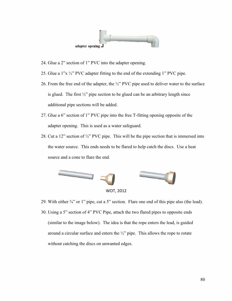
80
24. Glue a 2” section of 1” PVC into the adapter opening.
25. Glue a 1”x ½” PVC adapter fitting to the end of the extending 1” PVC pipe.
26. From the free end of the adapter, the ½” PVC pipe used to deliver water to the surface
is glued. The first ½” pipe section to be glued can be an arbitrary length since
additional pipe sections will be added.
27. Glue a 6” section of 1” PVC pipe into the free T-fitting opening opposite of the
adapter opening. This is used as a water safeguard.
28. Cut a 12” section of ½” PVC pipe. This will be the pipe section that is immersed into
the water source. This ends needs to be flared to help catch the discs. Use a heat
source and a cone to flare the end.
WOT, 2012
29. With either ¾” or 1” pipe, cut a 5” section. Flare one end of this pipe also (the lead).
30. Using a 5” section of 4” PVC Pipe, attach the two flared pipes to opposite ends
(similar to the image below). The idea is that the rope enters the lead, is guided
around a circular surface and enters the ½” pipe. This allows the rope to rotate
without catching the discs on unwanted edges.

81
WOT, 2012
31. Finally, sit the faucet into the open T-fitting of the frame as shown below.
32. With couplings, attach the desired depth of ½” PVC pipe to the faucet extension and
the flared extension.
33. With a diamond braded rope at the desired length (Lrope), slide ¼”M discs onto the
rope and tie a knot directly on either side. The discs should be spaced 8”-12” apart.

82
34. Place the rope and discs around the tire, and through the entire ½” pipe.
35. To attach the ends of the rope together, use an adjustable knot as shown below.
WOT, 2012
Appendix B-2d: Completed Assembly

83
Appendix C: Mathcad
Appendix C-1: Savonius-Darrieus and Rope Pump Calculations
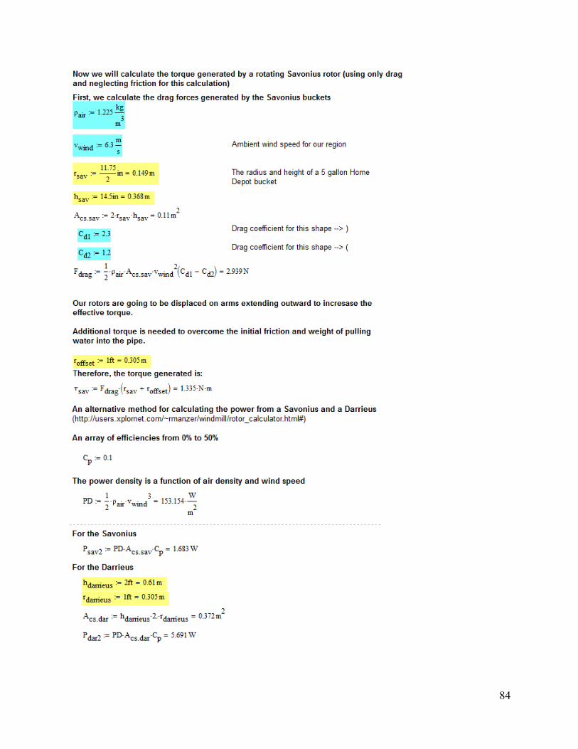
84

85
Appendix C-2: Piston Pump Calculations

86
Appendix C-3: Multistage Centrifugal Pump Calculations

87

88

89
References
Ages, E. M. Wind Power Overview.
Akvopedia. Retrieved February 27th, 2013, from
http://www.akvo.org/wiki/index.php/Rope_pump
Alibaba.com. (2013). Retrieved, 2013, from http://www.alibaba.com/
Anonymous. (1998). A short history of wind power. Countryside and Small Stock Journal, 82(5),
80.
Argaw, N., Foster, R., & Ellis, A. (2003). Renewable energy for water pumping applications in
rural villages . ( No. Subcontract No. RAM-1-31224-01). Golden, Colorado: National
Renewable Energy Laboratory.
Biofuels Congress. (2011). Advantages and disadvantages of wind power., April 2, 2012.
Brighton Webs Ltd. (2012). Vertical wind turbine. Retrieved, 2013, from http://www.brighton-
webs.co.uk/research/model_wind_turbines.htm
Chino, Mike (2008) Broadstar's AeroCam Breaks the Wind-Watt Barrier Retrieved December
12th, 2012 from http://inhabitat.com/broadstar-aerocam-breaks-wind-watt-barrier/
Classes of Wind Power Density at 10m and 50m. (n.d.). Retrieved from Renewable Resource
Data Center: http://rredc.nrel.gov/wind/pubs/atlas/tables/1-1T.html
Cole, J. (2013). Denmark 25% wind-powered, going for 50% in 8 years. Retrieved, 2013, from
http://www.juancole.com/2013/04/denmark-powered-years.html

90
Erne, Erik van (2010) The Most Beautiful Windturbines Ever Seen: The Wind Tulip and Wind
Lotus by Leviathan Energy Retrieved on December 14th, 2012 from
http://www.stichtingmilieunet.nl/andersbekekenblog/energie/the-most-beautiful-
windturbines-ever-seen-the-wind-tulip-and-wind-lotus-by-leviathan-energy.html
Experiments with Model Wind Turbines. (2012, 6 9). Retrieved 1 13, 2012, from Brighton-
Webs.co.uk: http://www.brighton-webs.co.uk/research/model_wind_turbines.htm
Gasch, R., & Twele, J. (2012). In Gasch R., Twele J.(Eds.), Wind pump systems Springer Berlin
Heidelberg. doi:10.1007/978-3-642-22938-1_10
Gears and Stuff. (2006). Different types of gears. Retrieved, 2013, from
http://www.gearsandstuff.com/types_of_gears.htm
Google Maps. (2013). Fraserburg, northern cape, south africa. Retrieved, 2013, from
https://maps.google.com/
Kamoji, M. A., Kedare, S. B., & Prabhu, S. V. (2009). Experimental investigations on single
stage modified savonius rotor. Applied Energy, 86(7–8), 1064-1073.
doi:10.1016/j.apenergy.2008.09.019
Layton, Julia (2006) How Wind Power Works, Retrieved December 12th, 2012 from
http://science.howstuffworks.com/environmental/green-science/wind-power2.htm

91
Letcher, T (2010) Small Scale Wind Turbines Optimized for Low Wind Speeds. Retrieved April
22nd
, 2013 from
http://kb.osu.edu/dspace/bitstream/handle/1811/45531/Hayes_Proceedings_Paper.pdf?seque
nce=1
LILI, 2012. Retrieved, 2013, from http://www.lowimpact.org/factsheet_wind_pumps.htm
Lohr, J. (2008). J.D. lohr west africa woodworking school project. Retrieved, 2013, from
http://www.jdlohrwood.com/news.htm
MacGarry. (2000). Pupil's guide to windpower. Great Britain: Centre for Alternative Technology
Publications.
Mathew, S., & Pandey, K. P. (2003). Modelling the integrated output of wind-driven roto-
dynamic pumps. Renewable Energy, 28(7), 1143-1155. doi:10.1016/S0960-1481(02)00185-
4
Menet, J., & Bourabaa, N.Increase in the savonius rotor's efficiency via a parametric
investigation., 3/25/2012.
Morrison, F. (1999). What is pumping head?
NERC. (2008). British geological survey.
OtherPower. (n.d.). Fieldlines.com. Retrieved from Otherpower:
http://www.fieldlines.com/index.php?topic=140906.0
92
Panemone (Drag-Type Windmill) (2003) Retrieved April 18th from
http://carpool.actrix.co.nz/projects/panemone.htm
Paraschivoiu, I. (2002). Wind turbine design with emphasis on darrieus concept Ecole
Polytechnique de Montreal.
Patel, M. (2006). Wind and solar power systems: Design, analysis, and operation (2nd ed.)
Taylor and Francis Group.
PES. (2012). Eight common turbine failures – and how to fix them. Retrieved, 2013, from
http://www.pes.eu.com/wind/eight-common-turbine-failures-and-how-to-fix-them/1109/
Practical Action. (2013). Windpumping.2013
PVC. (2013). PVC strength. Retrieved, 2013, from http://www.pvc.org/en/p/pvc-strength
Rehman, A. (2012). Wind turbine rotor.
Rye, Court (2008) Rye, 2008 Retrieved December 12th, 2012 from
http://windpowerauthority.com/rooftop-wind-power/
Savonius wind turbine. (2012). Retrieved 3/25, 2012,
from http://en.wikipedia.org/wiki/Savonius_wind_turbine
Savonius-rotor.jpg. In Wikipedia. Retrieved December 12th, 2012 from
http://ca.wikipedia.org/wiki/Fitxer:Savonius-rotor_en.svg

93
Sandru, Ovidiu (2009) Helix-Shaped Vertical Wind Turbines Will Power GSM Towers in Africa
& US, Retrieved December 14th, from
http://www.greenoptimistic.com/2009/10/01/helix-shaped-vertical-wind-turbines-will-
power-gsm-towers-in-africa-us/#.UMuFc-Q4ySo
Simon, M. R. (2011). Design and engineering of wind-powered machinery for developing
countries. Ohio State University / OhioLINK).
Smulders, P. T. (1996). Wind water pumping: The forgotten option. Energy for Sustainable
Development, II(5), 8.
Subramanian, R. Shankar., Engineering Bernoulli Equation, Retrieved April 22nd
,2013 from
http://web2.clarkson.edu/projects/subramanian/ch330/notes/Engineering%20Bernoulli%20E
quation.pdf
Survival Unlimited. (2013). Stainless steel pump
. Retrieved, 2013, from http://www.survivalunlimited.com/waterpumps/sppricelist.htm
Telsonet. (n.d.). Wind Power's Beginnings. Retrieved from Telsonet:
http://telosnet.com/wind/early.html
Toydemir,Kuthan C.Student author -- ME, Edremitlioglu,Hayrettin Hazal Student author -- ME,
Baskan,Ozan Student author -- ECE, & Emanuel,Alexander E.Faculty advisor -- EE.
(2008). Economical, environmental outcomes of wind energy production in turkey.
Worcester, MA: Worcester Polytechnic Institute.
94
U.S. Department of Energy. (2007). Small wind electric systems: A U.S. consumer's
guide. ().U.S. Department of Energy.
U.S. Department of Energy. (2012). Massachusetts 80-meter wind map and wind resource
potential. Retrieved 3/19, 2012,
from http://www.windpoweringamerica.gov/wind_resource_maps.asp?stateab=ma
U.S. Energy Information Administration. (2011). How dependent are we on foreign oil?., March
19, 2012.
U.S. Energy Information Administration. (2011). How much of the world's electricity supply is
generated from wind and who are the leading generators?, March 19, 2012.
U.S. Energy Information Administration. (2011). Trends in renewable energy consumption and
electricity 2009., March 19, 2012.
Union Of Concerned Scientists. (2009). How wind energy works.
Valdès, L. -., & Ramamonjisoa, B. (2006). Optimised design and dimensioning of low-
technology wind pumps. Renewable Energy, 31(9), 1391-1429.
doi:10.1016/j.renene.2005.06.016
Voneschen, M. F.Brief introduction to the darrieus wind turbines. [Introducción a la teoría de las
turbinas eólicas]
Water Project. (2013). Retrieved, 2013, from http://thewaterproject.org/

95
Wind Coalition. (2013). History of wind energy. Retrieved, 2013, from
http://windcoalition.org/wind-energy/history-of-wind-energy/
Wind Energy. (2006). The cost of energy generated by wind power. Retrieved, 2013, from
http://www.wind-energy-the-facts.org/en/part-3-economics-of-wind-power/chapter-1-cost-
of-on-land-wind-power/the-cost-of-energy-generated-by-wind-power.html
Wind Power (2007), Retrieved on April 17th
, 2013 from
http://www.fao.org/docrep/010/ah810e/AH810E10.htm#Fig. 109
Wind Power Wiki. (n.d.). Retrieved from Wind Power Wiki:
http://wiki.windpower.org/index.php/Upwind/downwind
Windpump (2013), In Wikipedia, Retrieved April 9th
, 2013 from
http://en.wikipedia.org/wiki/Windpump
Werner Sölken. (2013). Introduction to pumps - centrifugal pumps. Retrieved, 2013, from
http://www.wermac.org/equipment/pumps_centrifugal.html
Wortman, A. (1983). Introduction to wind turbine engineering Butterworth Publishers.
WOT. (2012). Retrieved Dec, 2013,
from http://www.wot.utwente.nl/publications/ropepump/rope-pump-manual-wot-english.pdf