an analysis of the effect of the application of...
TRANSCRIPT

ADVANCES IN MANUFACTURING SCIENCE AND TECHNOLOGY
Vol. 40, No. 1, 2016 DOI: 10.2478/amst-2016-0002
Address: Jadwiga PISULA, PhD Eng., Rzeszow University of Technology, Department of Mechanical Engineering, Powstańców Warszawy 8, 35-959 Rzeszów, e-mail: [email protected]
AN ANALYSIS OF THE EFFECT OF THE APPLICATION OF HELICAL MOTION AND ASSEMBLY ERRORS
ON THE MESHING OF A SPIRAL BEVEL GEAR USING DUPLEX HELICAL METHOD
Jadwiga Pisula
S u m m a r y
This article presents the effect of the helical motion parameter, specific for the Duplex Helical method, on the obtained pinion tooth flanks and on the correctness of contact in a spiral bevel gear. Furthermore, the gear's sensitivity to assembly errors is demonstrated. The analyses are based on the designed mathematical model of cutting bevel teeth with a circular pitch line and the mathematical model of the design gear. The results are presented for the selected gear with the ratio 20:37.
Keywords: spiral bevel gears, Duplex Helical method, contact pattern
Analiza wpływu ruchu śrubowego i błędów montażu na współpracę przekładni stożkowej
o kołowej linii zęba wykonanej metodą Duplex Helical
S t r e s z c z e n i e
W pracy przedstawiono analizę wpływu parametru ruchu śrubowego, charakterystycznego dla metody Duplex Helical, na dokładność wykonania powierzchni bocznej zęba zębnika oraz poprawność współpracy zazębienia przekładni stożkowej o kołowej linii zęba. Ustalono ponadto wrażliwość tej przekładni na błędy montażu. Podstawą analizy jest opracowany model matematyczny nacinania uzębienia stożkowego o kołowej linii zęba i model matematyczny przekładni konstrukcyjnej. Uzyskano wyniki dla wybranej przekładni o przełożeniu 20:37.
Słowa kluczowe: koła zębate stożkowe o kołowej linii zęba, metoda Duplex Helical, ślad styku
1. Introduction
The Duplex Helical method involves cutting (milling) or grinding spiral bevel gears by means of a helical machining motion. It is a dual two-sided method, i.e. both sides of the gear wheel and pinion teeth are cut simultaneously using two-sided cutter heads or grinding wheels. There are two variants of the Duplex Helical method: formate (for gear wheels with a large number of teeth) and generated approach. In the formate approach, the gear wheel is cut using the formate (non-generated) method, whereas the pinion is generated; the generated approach

20 J. Pisula
involves generating both parts of the transmission. An obvious advantage of the Duplex Helical method is shorter machining time. However, the application of the method is limited to machine tools which provide helical motion [1, 2]; it may be used for fabricating gears with small modules and a ratio of up to 2.5.
The appropriate selection of technological parameters for cutting gear wheels by means of the Duplex Helical method, so that the gear satisfies requirements arising from design assumptions in terms of a specific contact pattern and motion graph, is very difficult. In addition, simultaneous cutting of the entire tooth space increases the gear's sensitivity to machining errors and assembly errors. The application of helical motion, accomplished as an additional motion of the table with the fast headstock of the machined gear wheel, allows us to achieve the correct gear meshing determined by means of contact pattern and motion graph.
2. A model of technological gear including the application of the Duplex Helical method
A mathematical model of spiral bevel gear cutting was used in order to determine the effect of the helical motion parameter on simultaneously obtained convex and concave surfaces of the tooth space. The mathematical model of tooth surfaces involves determining an envelope of the family of tool's surfaces of action by means of a kinematic method [3]. The method makes use of kinematic relationships between mating surfaces, in this specific case between the family of the tool's surfaces of action and the resulting concave or convex tooth surface. The kinematic relationship between the mating surfaces is transcribed in the form of a meshing equation. The unknown envelope is the solution to the meshing equation supplemented with the equation of the family of the tool's surfaces of action [3÷6].
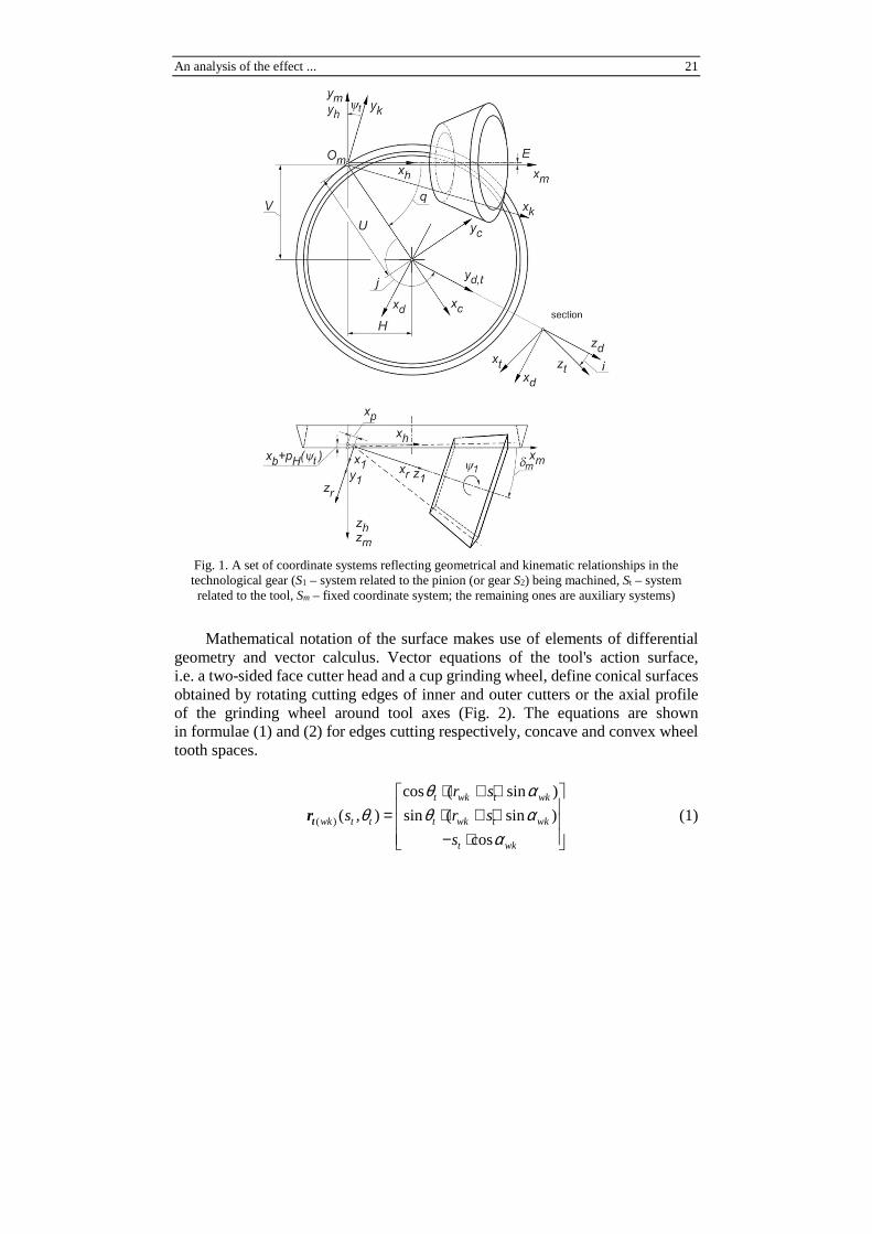
The mathematical model of spiral bevel gear cutting involves defining a set of dextrorotatory Cartesian coordinate systems reflecting geometrical and kinematic relationships between the machine tool's main assemblies. Fig. 1 presents coordinate systems related to the sub-assemblies of a conventional machine tool, including the application of an additional motion modifying the machining motion. Individual systems are marked with an upper-case Si, the index of which refers to a specific sub-assembly of the machine tool reflecting the position or motion relative to another sub-assembly. The helical machining motion is performed by the axial feed of the table with an attached fast headstock of the machined pinion, which is suitably coupled with the machining motion performed by the cradle [2].
An analysis of the effect ... 21
Fig. 1. A set of coordinate systems reflecting geometrical and kinematic relationships in the technological gear (S1 – system related to the pinion (or gear S2) being machined, St – system related to the tool, Sm – fixed coordinate system; the remaining ones are auxiliary systems)
Mathematical notation of the surface makes use of elements of differential geometry and vector calculus. Vector equations of the tool's action surface, i.e. a two-sided face cutter head and a cup grinding wheel, define conical surfaces obtained by rotating cutting edges of inner and outer cutters or the axial profile of the grinding wheel around tool axes (Fig. 2). The equations are shown in formulae (1) and (2) for edges cutting respectively, concave and convex wheel tooth spaces.
( )
cos ( sin )
( , ) sin ( sin )
cos
t wk t wk
wk t t t wk t wk
t wk
r s
s r s
s
θ αθ θ α
α
⋅ + ⋅ = ⋅ + ⋅ − ⋅
tr (1)

22 J. Pisula
( )
cos ( sin )
( , ) sin ( sin )
cos
t wp t wp
wp t t t wp t wp
t wp
r s
s r s
s
θ αθ θ α
α
⋅ − ⋅ = ⋅ − ⋅ − ⋅
tr (2)
for 1 2 1 2, t ts s s θ θ θ≤ ≤ ≤ ≤ , where: t ts , θ – curvilinear coordinates of surfaces
shaping concave and convex tooth space surfaces, wk wp,α α – tool action surface
profile angles, wk wpr ,r – radial locations of head cutters or of the grinding wheel,
or – nominal radius of the head, 2W – head cutter spacing or grinding wheel face width.
Fig. 2. Tool action surfaces machining the concave and the convex side of bevel gear tooth space
(parameters described in the text)
For conical surfaces of the tool's cutting concave and convex tooth space surfaces, normal unit vectors were determined, which were presented in equations (3) and (4) respectively.
( )
cos cos
( ) sin cos
sin
t wk
wk t t wk
wk
θ αθ θ α
α
− ⋅ = − ⋅ −
tn (3)
t wp
(wp) t t wp
wp
cos cos
( ) sin cos
sin
θ αθ θ α
α
− ⋅ = − ⋅
tn (4)
An analysis of the effect ... 23
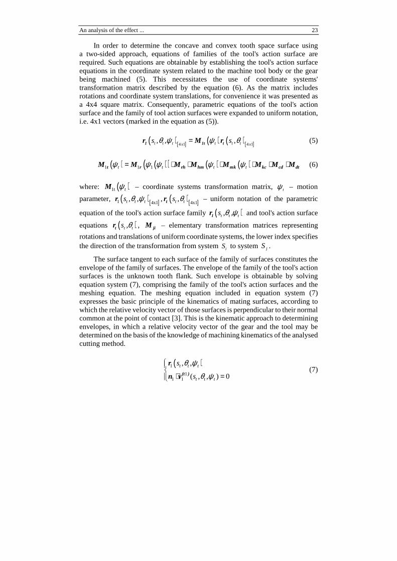
In order to determine the concave and convex tooth space surface using a two-sided approach, equations of families of the tool's action surface are required. Such equations are obtainable by establishing the tool's action surface equations in the coordinate system related to the machine tool body or the gear being machined (5). This necessitates the use of coordinate systems' transformation matrix described by the equation (6). As the matrix includes rotations and coordinate system translations, for convenience it was presented as a 4x4 square matrix. Consequently, parametric equations of the tool's action surface and the family of tool action surfaces were expanded to uniform notation, i.e. 4x1 vectors (marked in the equation as (5)).
( )[ ] ( ) ( )[ ]4 1 4 1, , ,t t t t t tx x
s sθ ψ ψ θ=1 1t tr M r (5)
( ) ( )( ) ( ) ( )1 1 1= ⋅ ⋅ ⋅ ⋅ ⋅ ⋅t t t tψ ψ ψ ψ ψt r rh hm mk kc cd dtM M M M M M M M (6)
where: ( )1t tψM – coordinate systems transformation matrix, tψ – motion
parameter, ( )[ ]1 4x1, ,t t ts θ ψr , ( )[ ]4x1
,t ts θtr – uniform notation of the parametric
equation of the tool's action surface family ( )t t ts , ,θ ψ1r and tool's action surface
equations ( )t ts ,θtr , jiM – elementary transformation matrices representing
rotations and translations of uniform coordinate systems, the lower index specifies the direction of the transformation from system iS to system jS .
The surface tangent to each surface of the family of surfaces constitutes the envelope of the family of surfaces. The envelope of the family of the tool's action surfaces is the unknown tooth flank. Such envelope is obtainable by solving equation system (7), comprising the family of the tool's action surfaces and the meshing equation. The meshing equation included in equation system (7) expresses the basic principle of the kinematics of mating surfaces, according to which the relative velocity vector of those surfaces is perpendicular to their normal common at the point of contact [3]. This is the kinematic approach to determining envelopes, in which a relative velocity vector of the gear and the tool may be determined on the basis of the knowledge of machining kinematics of the analysed cutting method.
( )1
11 1
, ,
( , , ) 0
⋅ =
t t t
t t t
s
s
θ ψ
θ ψ(t )
r
n v (7)

24 J. Pisula
where: ( )1 , ,t t ts θ ψr – parametric equation of the family of tool's action surfaces,
1n – normal unit vector in the pinion-related system 1,S 11 ( , , ) t t ts θ ψ(t )v – relative
velocity vector of the tool in relation to the pinion being machined in the pinion-related system 1S . If we substitute 2 for index 1, the dependences will refer to the gear wheel.
Thus determined lateral surface (flank) constitutes a set of points being the numerical solution to the equation system (7). The number and location of the points defining the tooth flank corresponds to the points on the reference grid located in the axial section of the pinion's or the gear wheel's tooth. Having arrived at a finite set of solutions (values) corresponding to the coordinates of the tooth's lateral surface, we may conduct an interpolation to quickly find solutions for the remaining "internal" points on the tooth's lateral surface. Thus obtained surfaces will be used in the analysis of the effect of machining parameters on tooth flank geometry and to determine meshing parameters.
3. A mathematical model of bevel gear meshing
A mathematical model of design bevel gear with the inclusion of errors in the performance of gear components and assembly errors was used in the gear contact analysis. Figure 3 presents a set of orthogonal dextrorotatory coordinate systems reflecting kinematic and geometrical interdependences in the design bevel gear. Parameters H, V and J define assembly errors corresponding, respectively, to: a shift in the pinion's position towards its axis (H), a shift in the position of the pinion axis in the direction perpendicular to the gear wheel axis (V) and a shift in the position of the gear wheel towards its axis (J). Parameter ∆Σ is the difference between the actual axis intersection angle and its nominal value.
As the surfaces of pinion's and gear wheel's teeth mesh, specific contact conditions on which the gear's contact analysis is based are met. Namely, at momentary point of contact M common for both surfaces, the coordinates of momentary point of contact M are equal on both surfaces (8) and normal unit vectors of both surfaces overlap at the point of contact (9).
( ) ( )1 2=M Mr r (8)
( ) ( )1 2=M Mn n (9)
In addition, the condition of the location of the relative velocity vector of the point of contact of both surfaces on a common tangent plane constitutes a meshing equation included in formula (7), introducing a normal vector at the point

An analysis of the effect ... 25
of contact on one of mating planes and relative velocity of the point of contact of one surface in relation to another. Thus defined system of equations allows us to evaluate contact in the bevel gear.
The article present the gear contact analysis as total contact pattern.
Fig. 3. A set of coordinate systems reflecting geometrical and kinematic relationships in the design gear, including assembly errors: H, V, J, ∆Σ (S1 – pinion-related system, S2 – gear wheel-related system, Sf – fixed coordinate system; other systems are auxiliary)
4. An analysis of the effect of helical motion parameter on tooth flank
The analyses shown here were performed for a 20:37 bevel gear, for which basic geometry and set machining parameters and tool geometry using the Duplex Helical method are presented in Tables 1, 2 and 3.

26 J. Pisula
Table 1. Basic geometrical data of the 20/37 gear
Quantity Designation Pinion Gear
Number of teeth z 20 37
Hand of spiral – Left Right
External transverse module ��� 2.6 mm
Pressure angle �� 20° Shaft angle Σ 90° Spiral angle � 33°30’
Mean cone distance R 46.677 mm
Face width b 16.0 mm
External whole depth h 5.114 mm 5.099 mm
Clearance c 0.555 mm 0.571 mm
External height of addendum ℎ� 2.282 mm 2.261 mm
External height of tooth root ℎ� 2.831 mm 2.837 mm
Pitch angle � 28°23’34” 61°36’25”
Dedendum angle � 2°4’30” 3°34’32”
Addendum angle � 3°34’32” 2°4’30”
Table 2. Geometrical tool data
Tool parameters Pinion Gear Diameter of cutter head � 88.9 mm 88.9 mm
Width of the blade tip �� 0.998 mm 1.335 mm
Fillet radius ��� 0.555 mm 0.555 mm
Cutter pressure angle (outer) ��� 14°48’33” 12°
Cutter pressure angle (inner)
��� 25°53’49” 28°
Table 3. The basic setting data for the gear and the pinion processing
Basic machine settings Designation Pinion (both flanks) Gear (both flanks)
Cradle angle q 61°12’45” 58°23’17” Radial distance U 42.880 mm 42.949 mm Hypoid offset a -0.040 mm 0 mm
Machine root angle m
δ 22°54’52” 59°36’25”
Machine centre to back Xp -0.301 mm 0 mm Sliding base Xb 1.034 mm 4.583 mm Tilt angle i 1°13’35” 7°1’4”
Swivel angle j 147°16’59” -165°51’28” Roll ratio iodt 0.478619 0.880243
Helical motion pH -3.695794 mm/rad 0 mm/rad

An analysis of the effect ... 27
On the basis of data gathered in Tables 1, 2 and 3 and the mathematical model of the machined gear, concave and convex surfaces of the pinion and the gear wheel were generated as a set of points. The present study analyses the effect of a change in helical motion parameter pH on the resultant concave and convex surface so the pinion. The results are shown in Figures 4 and 5. Figure 4 contains a image of two tooth space surfaces of the pinion as a set of points. Lateral surfaces of the tooth space were marked red and were treated as reference surfaces, i.e. surfaces obtained on the basis of data contained in Tables 1-3. Next, helical motion parameter was changed to pH = –3.755794 [mm/rad] (the absolute value of the parameter was increased by 0.06). The effect of the change in the parameter was presented on the pinion's tooth space surfaces marked blue (Fig. 4). As differences in point locations are slight, the nature of the changes in the helical motion parameter should be interpreted as follows: a rise in the helical motion parameter causes larger quantities of material to be collected on the convex surface from the small modules and the dedendum, and on the concave surface from the small modules and the addendum, while the penetration boundary of the nominal surface and the altered surface lies close to the diagonal of the surface from relevant vertices (Fig. 4 indicates the penetration boundary of the surfaces by a change in the colour of surface points).
Fig. 4. The effect of the change in the helical motion parameter on the location of lateral surfaces of tooth space relative to the reference surface. Red points define reference surfaces for the convex and concave sides of the pinion's tooth space (pH = –3.695794 mm/rad), blue points for the convex and concave sides of the pinion's tooth space after the change in parameter pH = –3,755794 mm/rad
Figure 5 contains a quantitative presentation of the effect of the change in the helical motion parameter separately for the concave on convex surface of the pinion. These are graphs of the arc differential according to the formula (10) from the angular and radial coordinate of the polar coordinates of the points of the nominal and the altered surface. Positive values of the arc differential indicate that the material is collected from the surface, whereas negative values show that the material remains on the surface.

28 J. Pisula
( )_ 0 _ 1i i V i VR φ φ∆ = − (10)
where: ∆ – arc differential, iR – relevant radial coordinate of the points from the cylindrical coordinates, i _V 0φ , i _V 1φ – angular coordinates of the points of the
reference surface and the altered surface.
Fig. 5. The effect of the change in the helical motion parameter on the obtained side surfaces of pinion's tooth space presented in the arc differential graph determined from polar coordinates of
the points of the reference surface and the altered surface
5. An analysis of the bevel gear's sensitivity to assembly errors
The analysis was conducted for the perfect gear and a gear with intentionally introduced assembly errors, the values of which were presented in Table 4. The gear's contact quality was presented by means of a diagram of the contact pattern on the gear wheel's tooth flanks (Fig. 6). The contact pattern was obtained through penetration by pinion's surface to the depth of 5 m, which corresponds to the thickness of the ink used in the gear contact test [3].
Table 4. Offset values for transmission configuration parameters
Assembly errors Instance
a) b) c) d) Hypoid offset V, mm 0.05 0.00 0.00 0.00 Axial shift of pinion H, mm 0.00 0.05 0.00 0.00 Axial shift of gear J, mm 0.00 0.00 0.1 0.00 Shaft angle change ∆Σ, min 0 0 0 5

An analysis of the effect ... 29
Fig. 6. Contact pattern diagrams presented form the concave and convex surfaces of the gear wheel tooth 20:37 for the following instances: a) the perfect gear, b) a gear with a deviation of V = 0.05 mm, c) a gear with the deviation of H = 0.05 mm, d) a gear with the deviation of J = 0.1 mm, e) a gear with the deviation of DS = 5/60 deg
a)
b)
c)
d)
e)
Gear coast side (concave side)
Gear drive side (convex side)

30 J. Pisula
Changes in the location of the contact pattern presented on the gear wheel's lateral surfaces for the analysed gear were as follows:
• for a positive hypoid offset V, the contact pattern shifts in the direction of the addendum and small modules for the drive side of the tooth of the gear wheel, and in the direction of the addendum and large modules for the coast side of the tooth of the gear wheel,
• if a positive offset of pinion axis H is used, the contact pattern shifts towards the addendum for both gear wheel tooth surfaces,
• if a positive offset of gear wheel axis J is used, the contact pattern shifts towards the dedendum and slightly in the direction of large modules for both gear wheel tooth surfaces,
• if a positive (incremental) axis intersection error ∆Σ is introduced, the contact pattern shifts towards the addendum for the drive side of the gear wheel tooth, and towards the dedendum for the coast side of the gear wheel tooth.
The shifts in the contact pattern on the drive and the coast side are closely interrelated. This is a consequence of simultaneously machining of both tooth space surfaces for the gear and the pinion in the Duplex Helical method applied.
6. Conclusions
An analysis of the geometry of the lateral surface of the tooth space obtained with the Duplex Helical method using helical motion and the results of the simulation of the contact between the surfaces provides the basis for the gear's acceptance at the design stage and, more generally, offers guidance as to the design of a new gear according to the discussed approach. The approach is ready for implementation on conventional machine tools.
The introduction of a non-linear change in the helical motion will enable additional modifications to tooth surfaces. Obviously, it will be possible only by means of numerically-controlled machine tools which allow operators to input non-linear motion functions.
Manufacturers' interest in the Duplex Helical method seems quite rational. It is motivated mainly by economical production and the avoidance of problems arising at the bottom of the tooth space in dual two-sided methods. Researchers also seem to be interested in the discussed method, which is confirmed in publications such as [2-9]. The results of the studies will help in finding the correct way to design a spiral bevel gear.
References
[1] J. KLINGELNBERG (Hrsg.): Kegelräder. Grundlagen, Anwendungen. Springer-Verlag, Berlin Heidelberg 2008.

An analysis of the effect ... 31
[2] Z. WÓJCIK: Obrabiarki do uzębień kół stożkowych. Wydawnictwo Naukowo-Techniczne, Warszawa 1993.
[3] F.L. LITVIN, A. FUENTES: Gear geometry and applied theory, Second Edition, Cambridge Univ. Press, Cambridge 2004.
[4] Z.-H. FONG, Y.-P. SHIH, G. LIN: Mathematical model for a universal Face hobbing hypoid gear generator. Journal of Mechanical Design, 129(2007)1, 38-47.
[5] A. MARCINIEC: Analiza i synteza zazębień przekładni stożkowych o kołowo-łukowej linii zęba. Oficyna Wydawnicza Politechniki Rzeszowskiej, Rzeszów 2003.
[6] J. PISULA, M. PŁOCICA: Methodology of designing the geometry of the bevel gear using numerical simulation to generate the teeth flank surfaces. Acta Mechanica et Automatica, 8(2014)1, 5-8.
[7] I. GONZALEZ-PEREZ, A. FUENTES, K. HAYASAKA: Computerized design and tooth contact analysis of spiral bevel gears generated by the duplex helical method. Proc. ASME Inter. Design Conference Engineering Technical Conferences and Computers and Information in Engineering Conference, Washington 2011.
[8] J. PISULA, M. PŁOCICA: Numerical model of bevel gears cutting by duplex helical method. Key Engineering Materials, 490(2011), 237-246.
[9] Y. ZHANG, H. YAN, T. ZENG: Cutting principle and tooth contact analysis of spiral bevel and hypoid gears generated by duplex helical method. Journal of Mechanical Engineering, 51(2015).
Received in January 2016

Address: Jadwiga PISULA, PhD Eng., Rzeszow University of Technology, Department of Mechanical Engineering, Powstańców Warszawy 8, 35-959 Rzeszów, e-mail: [email protected]