an analytical solution for stability analysis of
TRANSCRIPT

Numerical Methods in Civil Engineering, Vol. 6, No. 1, September. 2021
Numerical Methods in Civil Engineering
An analytical solution for stability analysis of unrestrained tapered thin-
walled FML profile
M. Soltani*, A. Soltani**
ARTICLE INFO
Article history:
Received:
April 2021.
Revised:
July 2021.
Accepted:
August 2021.
Keywords:
Fiber-metal laminates; I-
section; Tapered beam;
Lateral-torsional
stability; Classical
lamination theory;
Galerkin’s method
Abstract:
The main purpose of this study is to compare the lateral buckling behavior of laterally
unrestrained Fiber-Metal Laminate (FML) and composite thin-walled beam with varying cross-
section under transverse loading. It is supposed that all section walls (the web and both flanges)
are composed of two metal layers at the outer sides of the fiber-reinforced polymer laminates.
The classical lamination theory and Vlasov’s model for thin-walled cross-section have been
adopted to derive the coupled governing differential equations for the lateral deflection and
twist angle. Employing an auxiliary function, the two governing equations are reduced to a
single fourth-order differential equation in terms of twist angle. To estimate the lateral buckling
load, Galerkin’s method is then applied to the resulting torsion equilibrium equation.
Eventually, the lateral stability resistance of FML and laminated composite web-tapered I-beam
under uniformly distributed load has been compared to each other considering the effects of
some significant parameters such as laminate stacking sequence, metal volume fraction,
transverse load position, and web tapering ratio. The results show that increasing the metal
volume fraction leads to enhance the linear buckling strength of glass-reinforced aluminum
laminate I-beam under transverse loading. For the optimum lamination, it is seen that the lateral
buckling load increases approximately 25% by raising the metal volume percentage from 0%
to 20%.
1. Introduction
Thin-walled members comprise a wide range of structural
elements. The profile of these elements includes connected
thin plates encompassing open, closed, or a combination of
both. These members are increasingly used in various
industries and engineering structures such as civil
engineering and aerospace due to their ability to consume
materials economically and optimize the weight of the
structure. Today, the fabrication of thin-walled beams
from various materials such as steel, wood, fiber-
reinforced composite materials, and functionally graded
materials has become possible by developing pultrusion
and assembly methods. Fiber metal laminations (FMLs)
are a new class of hybrid materials built from several thin
sheets of metal alloys and fiber-reinforced epoxy
composite plies. These laminates possess the desirable
features of metal such as ductility, damage tolerance,
excellent resistance to impact and environmental
* Corresponding Author: Assistant Professor, Department of civil
engineering, University of Kashan, Kashan, Iran, E-mail:
[email protected] ** MSc Student in Structural Engineering, Department of civil
engineering, University of Kashan, Kashan, Iran.
conditions, and advantages of the reinforced polymeric
composites such as good fatigue resistance, durability, and
high value of stiffness-to-weight and strength-to-weight
ratios. Due to the conspicuous characteristics of FMLs, the
use of fiber-metal hybrid composite structures in the
design of submarine and aircraft industries has become
increasingly common throughout the years. A literature
review shows that several investigations have been
performed on the behavior of laminated composite
components such as thin-walled beams, cylinders, shells,
and plates. In the following, a short description of some of
these studies is presented.
A new finite element formulation applicable for stability
analysis of arbitrary cross-sections of the tapered thin-
walled beams was described by Rajasekaran [1]. Nam et
al. [2] used a genetic algorithm to optimize the
arrangement of metal-fiber multilayer composite shells
under different loading cases. They indicated that metal-
fiber multilayer shells made of carbon fiber-reinforced
polymer laminates are more resistant to random and
unforeseen forces in most loading conditions. Based on the
classical lamination theory, Lee et al. [3-6] studied flexural
behavior, dynamics, and stability of thin-walled open and
Dow
nloa
ded
from
nm
ce.k
ntu.
ac.ir
at 8
:36
+03
30 o
n T
uesd
ay N
ovem
ber
23rd
202
1

51
closed beam profiles made of symmetrical multilayer fiber
composite using finite element method and cubic shape
function. Vibration and instability analyses of FGM
spinning circular cylindrical thin-walled beams were
performed by Oh et al. [7]. Rajasekaran and Nalinaa [8]
assessed the vibrational characteristics and buckling
behavior of non-prismatic composite spatial members
having generic thin-walled sections via the finite element
method within the context of the non-linear strain
displacement relationship. Magnucka-Blandzi [9]
examined the lateral stability limit state of simply
supported I-beam under combined loads, including
uniformly distributed load, longitudinal force, and gradient
moment. With the finite element methodology, the
flexural-torsional coupled free vibrational behavior and
buckling problem of thin-walled composite beams were
precisely investigated by Vo and Lee [10], considering the
impacts of axial load on the vibration characteristics. In
another study, Moon et al. [11] evaluated the buckling
behavior of a medium-thickness carbon-epoxy composite
cylinder under external hydrostatic pressure by modeling
in Nastran finite element software. To estimate the
buckling resistance of simply supported thin-walled
structural members made of Fiber Reinforced Polymer
(FRP) loaded by axially and uniformly transverse forces,
Ascione et al. [12] developed a mechanical model based
on the assumptions of small strains and moderate rotations.
Further, Arajo et al. [13] dynamically analyzed sandwich
sheets using natural materials and piezoelectric composite
layers by applying the finite element method. In another
study, Ravishankar et al. [14] reported the influence of
type fiber-reinforced epoxy composite materials, Metal
Volume Fraction (MVF), and angular velocity on the free
vibrational response of rotating beams made of FMLs and
or functionally graded materials using finite element
software. Banat et al. [15-17] evaluated the buckling
behavior of FMLs composite thin-walled beams with C-
and Z-shaped sections under axial compressive force using
ANSYS finite element software. Further, they perused the
effect of layer arrangement on the compressive capacity
and compared the outcomes of software modeling with
laboratory results. In addition, Hallival et al. [18], in a
laboratory study, investigated the behavior of fiber-metal
multilayers by adding resin under an impact force and
reported that adding resin between the layers results in
decreasing the separation by 40-50% and increasing the
compressive strength by approximately 30%. Based on a
generalized layered global-local beam (GLGB) theory,
Lezgy-Nazargah [19] proposed an efficient finite element
model for the elasto-plastic analysis of beams with thin-
walled cross-section. Mohandes and Ghasemi [20]
employed finite strain theory on free vibration of
microlaminated composite Euler-Bernoulli beam in a
thermal environment. Mohandes et al. [21] extracted the
equations governing the free vibration of the cylindrical
shell made of metal-fiber composite layers based on the
first-order shear deformation theory. Their work evaluated
various parameters such as different material properties of
composite fibers, lay-up arrangement, fiber angle,
boundary conditions, number of vibrational modes, and
metal volume fraction. In another study, Ahmadi and
Rasheed [22] employed the generalized semi-analytical
technique to analyze the lateral-torsional buckling of
anisotropic laminated beams with rectangular thin-walled
cross-section subjected to simply supported end supports
based on the classical laminated plate theory. Within the
context of first-order shear deformation theory and using a
semi-analytical solution methodology, the mechanical
response of thin-walled laminated beams with constant
open and/or closed cross-sections was assessed by
Wackerfuß and Kroker [23]. Through a one-dimensional
finite element model, Asadi et al. [24] analyzed the linear
stability behavior of laminated composite beams with thin-
walled open/closed sections under various boundary
conditions. In their study, the impacts of transverse shear
deformation and out-of-plane warping of the beam section
are considered. Within the context of Love’s first
approximation shell theory, Ghasemi and Mohandes [25]
presented a comparative study between the vibrational
responses of FML and composite cylindrical shells. Soltani
[26] perused the flexural-torsional buckling behavior of
the tapered sandwich I-beam with porous core using the
differential quadrature method. Additionally, the
mechanical responses of composite thin-walled beams
with different geometries and subjected to various types of
loading cases and end conditions were exhaustively
assessed by Lezgy-Nazargah et al. [27-32] using the
concept of equivalent layered composite cross-section.
As mentioned earlier, most of the studies conducted on the
behavior analysis of fiber/metal laminated composites
have focused on cylindrical shells, while few laboratory
studies have been performed on the stability characteristics
of thin-walled FML beams [15-17]. Due to the application
of hybrid fiber-metal composite thin-walled elements in
aircraft and spacecraft structures and the blades of wind
turbines and helicopters, there is a strong scientific need to
precisely assess the lateral stability strength of thin-walled
FML profile under transverse loads. Thus, the current
research is aimed to probe the lateral-torsional buckling
characteristics of FML tapered I-beams according to
Vlasov’s assumptions [33]. Based on this model and using
small displacements theory, the lateral-torsional stability
behavior of thin-walled beams with arbitrary laminations
is usually governed by three fourth-order differential
equations coupled in terms of the lateral and vertical
displacements as well as the torsion angle. Perusing the
critical state of thin-walled composite members subjected
to combined transverse loads and compressive axial force
is complicated in the presence of flexural-torsional
coupling. This procedure seems to be more problematic in
the presence of thin-walled beams with varying web and/or
flanges. To investigate the lateral buckling behavior of this
type of member, the 12*12 static and buckling stiffness
matrices can also be formulated based on twelve
displacement parameters, namely: two translations, twist,
two rotations, and warping at each end node [3-6, 10]. In
the case of doubly-symmetric thin-walled composite
beams with symmetric laminations under bending moment
about the strong principal axis of the cross-section, a two-
noded element with four degrees of freedom at each node
and resultantly 8*8 static element stiffness matrices are
commonly required to study the lateral stability behavior
Dow
nloa
ded
from
nm
ce.k
ntu.
ac.ir
at 8
:36
+03
30 o
n T
uesd
ay N
ovem
ber
23rd
202
1
Numerical Methods in Civil Engineering, Vol. 6, No. 1, September. 2021
[3-6, 10]. Although the finite element technique is capable
of estimating the buckling loads with the desired precision,
it requires a considerable amount of time to be executed.
For this reason, the linear lateral buckling behavior of
tapered thin-walled FML beam with doubly-symmetric I-
section is analyzed by means of Galerkin’s method. The
main advantage of this methodology is simplicity,
reducing computational effort, and consequently saving
computing time. To this end, the following steps are
considered:
Using classical laminated theory and energy method, the
coupled governing differential lateral-torsional stability
equations for the lateral deflection and torsion are
extracted by implementing Vlasov’s model for thin-walled
cross-sections. Following the methodology expanded by
Soltani et al. [34-36], the two lateral stability equations are
uncoupled and reduced to a single fourth-order differential
equation in terms of the twist angle. The resulting
formulation can be applied for calculating the lateral-
buckling load of laminated composite I-beam under
different boundary conditions and loading cases. However,
only the simply supported beam with free warping at both
supports is considered in this study. The trigonometric
function, which satisfies the simply supported beam end
conditions, is then used to acquire the analytical solutions
with Galerkin’s method. To check the accuracy and the
efficiency of the proposed methodology, our results are
compared with numerical ones from the ANSYS code, and
good agreement is observed. By performing a
comprehensive parametric example, the outcomes of
lateral buckling analysis of simply supported laminated
web-tapered I-beam under uniformly distributed load is
given in terms of the impacts of some representative
parameters such as lay-up arrangement, metal volume
fraction, web tapering ratio, and loading position. Finally,
the best lay-up of the internal fiber composite layers is
introduced by examining different stacking sequences.
2. Formulations
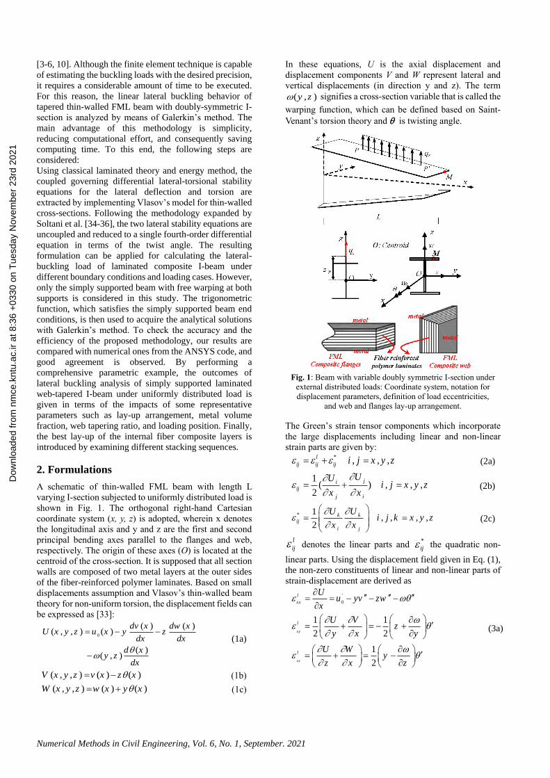
A schematic of thin-walled FML beam with length L
varying I-section subjected to uniformly distributed load is
shown in Fig. 1. The orthogonal right-hand Cartesian
coordinate system (x, y, z) is adopted, wherein x denotes
the longitudinal axis and y and z are the first and second
principal bending axes parallel to the flanges and web,
respectively. The origin of these axes (O) is located at the
centroid of the cross-section. It is supposed that all section
walls are composed of two metal layers at the outer sides
of the fiber-reinforced polymer laminates. Based on small
displacements assumption and Vlasov’s thin-walled beam
theory for non-uniform torsion, the displacement fields can
be expressed as [33]:
0
( ) ( )( , , ) ( )
( ) ( , )
dv x dw xU x y z u x y z
dx dx
d xy z
dx
(1a)
( , , ) ( ) ( )V x y z v x z x (1b)
( , , ) ( ) ( )W x y z w x y x (1c)
In these equations, U is the axial displacement and
displacement components V and W represent lateral and
vertical displacements (in direction y and z). The term
( , )y z signifies a cross-section variable that is called the
warping function, which can be defined based on Saint-
Venant’s torsion theory and is twisting angle.
Fig. 1: Beam with variable doubly symmetric I-section under
external distributed loads: Coordinate system, notation for
displacement parameters, definition of load eccentricities,
and web and flanges lay-up arrangement.
The Green’s strain tensor components which incorporate
the large displacements including linear and non-linear
strain parts are given by: * , , ,l
ij ij ij i j x y z (2a)
1( ) , , ,
2
ji
ij
j i
UUi j x y z
x x
(2b)
* 1 , , , ,
2
k k
ij
i j
U Ui j k x y z
x x
(2c)
l
ij denotes the linear parts and
*
ij the quadratic non-
linear parts. Using the displacement field given in Eq. (1),
the non-zero constituents of linear and non-linear parts of
strain-displacement are derived as
'
0
1 1
2 2
1
2
xy
xz
l
xx
l
l
Uu yv zw
x
U Vz
y x y
U Wy
z x z
(3a)
Dow
nloa
ded
from
nm
ce.k
ntu.
ac.ir
at 8
:36
+03
30 o
n T
uesd
ay N
ovem
ber
23rd
202
1

53
* 2 2 2 2 2 2
*
*
1 1( ) ( ) ' ' '
2 2
' ' ' '
1 1
2 2
1 1
2 2
xx
xy
xz
V Wv w r
x x
yw zv
V V W Ww y
x y x y
V V W Wv z
x z x z
(3b)
In Eq. (3b), the term 2r represents 2 2y z .
The resultants of classical stresses for beams with doubly-
symmetric I-section can be expressed as follows [26]
, , , 1, , ,
( ) ( )
y z xxA
sv xz xy
A
N M M B z y dA
M y z dAz y
(4)
where N is the axial force. My and Mz denote the bending
moments about major and minor axes, respectively. B is
the bi-moment. Msv is the St-Venant torsion moment. The
present model is applied in the case of balanced and
symmetrical lay-ups of the web and both flanges. In the
context of classical laminated plate theory and substitution
Eq. (3a) into Eq. (4), the stress resultants of symmetrically
balanced laminates are derived in terms of displacement
components as [3]
0( ) ; ( ) ;
( ) ; ( ) ;
( )
com z z com
y y com com
sv com
N EA u M EI v
M EI w B EI
M GJ
(5)
where ( )com
EA denotes axial rigidity. ( )y com
EI and
( )z com
EI represent the flexural rigidities of the y- and z-
axes, respectively. ( ) com
EI and ( )com
GJ are, respectively,
warping and torsional rigidities of composite thin-walled
beams with doubly symmetric I-section, defined by:
11 11
3
11 11
2 3
11 11 11
32 3
11 11 11
66 66
( ) 2 ;
( ) 212
( ) 2 24 12
( ) 2( ) ;4 12 12
( ) 4(2 )
f w
com f
f wf
z com
f f w
y com f f
f f wf
com
f w
com f
EA b A dA
bEI A dD
d dEI b D b A A
bd dEI A D D
GJ b D dD
(6)
That indexes f and w refer to the web and the flange of the
beam cross-section, respectively. ijA and
ijD are the
matrices of extensional and bending stiffness, respectively.
These stiffness quantities for composite multi-layer I-
section could be calculated as: 2( , ) (1, )f f f
ij ij ijA D Q z dz (7a)
2( , ) (1, )w w w
ij ij ijA D Q y dy (7b)
where f
ijQ and w
ijQ are the transformed reduced stiffness
related to the flanges and web, respectively. In this
research, equilibrium equations and boundary conditions
are derived from stationary conditions of the total potential
energy. Based on this principle, the following relation is
obtained
0 0l eU U W (8)
In this formulation, denotes a variational operator. lU
and 0U represent the elastic strain energy and the strain
energy due to effects of the initial stresses, respectively.
We denotes work done by external applied loads. Ul could
be computed using the following equation
0
0 02 2
Ll l
l ij ij xx xxV A
L Ll l
xy xy xz xzA A
U dV dAdx
dAdx dAdx
(9)
in which, L expresses the element length. l
ij is the
variation of the linear parts of strain tensor. Using Eq. (3a),
the variation of the linear part of strain tensor components
is given by: '
0
'
'
;
1;
2
1
2
xz
xy
l
xx
l
l
u y v z w
yz
zy
(10)
Substituting equation (10) into relation (9) and integrating
over beam’s cross-section, the expression of the strain
energy variation can be carried out as:
00
0
0
0
0
( )
( )
L
l xxA
L
xyA
L
xzA
z yL
L
sv
U u y v z w dAdx
z dAdxy
y dAdxz
N u M v M w B dx
M dx
(11)
Substituting Eq. (5) into Eq. (11) yields:
0 0( ) ( )
( )
( ) ( )
com z com
l y comL
com com
EA u u EI v v
U EI w w dx
EI GJ
(12)
Also, the variation form of strain energy due to initial
stresses can be stated as
0 * 0 *
00
0 * 0 *
0 02 2
L
ij ij xx xxV A
L L
xy xy xz xzA A
U dV dAdx
dAdx dAdx
(13)
In Eq. (13), 0
xy and 0
xz indicate the mean values of the
shear stress and 0
xx signifies initial normal stress in the
cross-section. According to Fig. 1, it is contemplated that
the external bending moment occurs about the major
principal axis ( *
yM ). Therefore, the magnitude of bending
moment with respect to z-axis is equal to zero. Regarding
this, the most general case of normal and shear stresses
associated the external bending moment *
yM and shear
force Vz are considered as: * *
0 0 0; ; 0 y yz
xx xz xy
y
M MVz
I A A
(14)
Dow
nloa
ded
from
nm
ce.k
ntu.
ac.ir
at 8
:36
+03
30 o
n T
uesd
ay N
ovem
ber
23rd
202
1

Numerical Methods in Civil Engineering, Vol. 6, No. 1, September. 2021
Based on Eq. (3b), the first variation of non-linear strain-
displacement relations can be written as:
* 2
*
*
' '
' ' ' ' ' '
1 1
2 2
1 1
2 2
xx
xy
xz
v v w w r yw
y w z v zv
w y w y
v z v z
(15)
Substituting equations (14) and (15) into relation (13)
yields:
* 2
00
*
0
( )' ' ' '
' ' '
( )
Ly
Ay
Ly
A
v v w w
M rU z dAdx
I y w yw
z v zv
M v vdAdx
z zA
(16)
In this stage, by integrating Eq. (16) over the cross-section
area of the beam, the final form of the variation of strain
energy due to the initial stresses is acquired as
* *
00
L
y yU M v M v dx (17)
The first variation of external load work (We) of the beam
under distributed vertical forces qz applied along a line
(PP′) on the section contour (Fig. 1a) can be written in the
form of
0
L
e z pW q w dx (18)
In Eq. (18), wP is the vertical displacement of point P.
According to kinematics used in Asgarian et al. [34] and
by adopting the quadratic approximation, the vertical
displacement of the point P and its first variation are as
follows: 2
2
P P P Pw w z w w z
(19a, b)
In this equation, zP is used to imply the eccentricity of the
applied loads from the centroid of the cross-section.
Substituting Eq. (19b) into Eq. (18) yields
0
L
e z tW q w M dx (20)
in which, t z P
M q z denotes the second order torsion
moment due to load eccentricity.
After inserting Eq. (12), (16) and (20) into Eq. (8), the
expression of the firs variation of total potential energy can
be written as
0 0
* *
0
0
( ) ( )
( )
( ) ( )
0
com z com
y comL
com com
L
y y
L
z t
EA u u EI v v
EI w w dx
EI GJ
M v M v dx
q w M dx
(21)
Based on the equation presented above, the first variation
of the total potential energy contains the virtual
displacements ( , , ,u v w ) and their derivatives.
After appropriate integrations by parts, and after
mathematical simplifications, we get the following
equilibrium equations in the stationary state
0(( ) ) 0
comEA u
(22a)
( )y com z
EI w q (22b)
*( ) 0z com y
EI v M
(22c)
*( ) ( ) 0com com y t
EI GJ M v M
(22d)
The related boundary conditions at the ends of balanced
laminated beam with thin-walled cross-section can be
expressed as
0( ) 0comEA u or 0
0u (23a)
( ) 0z com
EI v or 0v (23b)
*(( ) ) ( ) 0z com y
EI v M or 0v (23c)
( ) 0y com
EI w or 0w (23d)
(( ) ) 0y com
EI w or 0w (23e)
( ) 0com
EI
or 0 (23f)
(( ) ) ( ) 0com com
EI GJ
or 0 (23g)
In the equilibrium equations, the first and second ones are
uncoupled and stable, and do not affect the lateral buckling
behavior of I-beam subjected to transverse loading. The
differential equations (22c, d) have a coupled nature due to
the presence of the lateral deflection v and torsion
component, as well as the bending moment *
yM . Based
on the straightforward methodology presented by Soltani
et al. [34-36], the governing equilibrium equation for the
lateral displacement (22b) can be rewritten as
(24)
*
( )
y
z com
Mv
EI
whose substitution in the fourth equilibrium Eq. (22d)
enables its redefinition in an uncoupled form as only
dependent on the twist angle , independent from the
lateral displacement v , i.e.
* 2
( ) ( ) 0( )
y
com com t
z com
MEI GJ M
EI
(25)
Eqs. (23f) and (23g) are the corresponding boundary
conditions of the resulting formulation.
Since the flanges and/or web are variable, all stiffness
quantities of the composite beam are functions of the x-
coordinate. In this regard, the solution of the resulting
fourth-order differential equation in terms of the twist
angle (25) is not straightforward and only analytical or
numerical techniques such as Galerkin’s or Rayleigh-Ritz
methods [37-39], the finite difference method [40, 41], the
differential quadrature method [26, 36, 42, 43], and the
power series method [44-46] are feasible. In the present
work, Galerkin’s method as a highly accurate analytical
methodology is used to solve Eq. (25) and obtain the lateral
buckling load. Additionally, this analytical approach is one
of the most easy-to-apply methodologies to exactly
determine the lateral stability strength of unrestrained and
braced continuous structural elements. Based on the
assumptions of this technique, the differential equilibrium
Dow
nloa
ded
from
nm
ce.k
ntu.
ac.ir
at 8
:36
+03
30 o
n T
uesd
ay N
ovem
ber
23rd
202
1
55
equations and approximate displacement functions are
required. Note that the assumed buckled deformations
should satisfy the geometric boundary conditions of the
beam. It is also necessary to mention that the resulting
fourth-order differential equation (Eq. (25)) is applicable
for lateral stability analysis of composited tapered I-beams
that are restrained from the torsion at their ends
( (0)= (L)=0 ).
For simply supported beams with free warping at both ends
( (0) (L) 0 ), the twist angle also equals zero (
(0)= (L) 0 ). For this condition, the first displacement
mode in torsion after lateral buckling can be thus
approximated by trigonometric function as [38, 39]
1( ) sin
xx
L
(26)
In the case of fixed-fixed members, both supports are
prevented from freely warping. Therefore, the twist angle
and the rate of twist at the fixed ends are restrained (
(0)= (L) (0) (L) 0 ). The expression for the
angle of twist can be approximated as [38, 39]
1
2 3
2( ) (1 cos )
3 5(1 cos ) (1 cos )
xx
L
x x
L L
(27)
For the fixed-simply supported I-beams, the left end (fixed
one) of the beam are prevented from freely warping (
(0)= (0) 0 ), while, the right end of the element is free
to warp but restrained from the torsion ( (0)= (L) 0 ).
One gets [38, 39]: 4 3 2
1
2
( ) ( 2.5 1.5 )
sin
cos
x x xx
L L L
kx xk
L L
kxk k
L
(28)
where ( 1,2,3)i
i is the associated displacement
amplitude.
In the current work, only simply supported beam with free
warping and bending at both ends is considered. Following
the rules of Galerkin’s method and by substituting the
buckled shape function and its derivatives into Eq. (25) one
gets * 2
2 2
2
(( ) )(sin( ))( )
( ) (( ) sin( )) sin( )
( )(( ) cos( )) sin( )
y
P zL
z com
com
L
com
M xz q dx
L EI L
x xEI
L L Ldx
x xGJ
L L L
(29)
By substituting the required stiffness coefficients as well
as the bending and torsion moments expressions into the
formulation presented above following an appropriate
mathematical procedure, the lateral-torsional buckling
load can be acquired.
3. Findings and Discussion
In the preceding section, an analytical methodology has
been formulated to calculate the lateral-torsional buckling
loads of thin-walled fiber metal laminates beam with
varying I-section. In this section, a comprehensive
example is conducted to show the effects of significant
parameters such as laminate stacking sequences, metal
volume fraction, loading position, and web tapering ratio
on the lateral buckling capacity of multi-layered composite
tapered I-beam. In this regard, the linear lateral buckling
analysis is performed for a simply supported 10-layer FML
web tapered I-beam with a span of 10m. All section walls
(both flanges and web) are laminated symmetrically
concerning its mid-plane and made of Aluminum alloy
2024-T3 (outer metal layers) and E-glass/epoxy material
(eight inner composite layers). The material features of the
lamina are as follows [25]: for the aluminum plies, E =
72.4 GPa and υ = 0.33; and for the fiber-reinforced
composite layers, Ex = 38.6 GPa, Ey = 8.27 GPa, Gxy =
4.14 GPa, and υxy = 0.26.
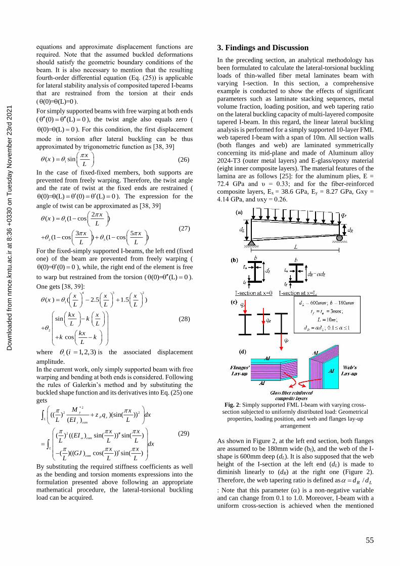
Fig. 2: Simply supported FML I-beam with varying cross-
section subjected to uniformly distributed load: Geometrical
properties, loading position, and web and flanges lay-up
arrangement
As shown in Figure 2, at the left end section, both flanges
are assumed to be 180mm wide (bf), and the web of the I-
shape is 600mm deep (dL). It is also supposed that the web
height of the I-section at the left end (dL) is made to
diminish linearly to (dR) at the right one (Figure 2).
Therefore, the web tapering ratio is defined as /R Ld d
: Note that this parameter () is a non-negative variable
and can change from 0.1 to 1.0. Moreover, I-beam with a
uniform cross-section is achieved when the mentioned
Dow
nloa
ded
from
nm
ce.k
ntu.
ac.ir
at 8
:36
+03
30 o
n T
uesd
ay N
ovem
ber
23rd
202
1

Numerical Methods in Civil Engineering, Vol. 6, No. 1, September. 2021
parameter () equals one. For the above case, the required
stiffness quantities presented in Eq. (6) can be rewritten as
follows:
11 11
1( ) ( 1)( )
6
f w
z com f L L
xEI b A d d D
L
(30)
3
11
2
3
11
3
11
1( )
6
1( 1)( )
24
1( 1)( )
12
f
com f
f
L L f
w
L L
EI b D
xd d b A
L
xd d D
L
66 66( ) 8 4 ( 1)( )f w
com f L L
xGJ b D d d D
L
As shown in Fig. 2, the selected simply supported web-
tapered beam is subjected to uniformly distributed load.
For this loading case, the internal bending moment in the
beam equals 2 2
*
2( )
2y z
L x xM q
L L
(31)
The uniformly transverse load is also supposed to be
applied at three different positions: the top flange, the
centroid (shear center), and the bottom flange. The load
height parameter (zP) and, consequently, the second-order
torsion moment can be written as:
0.5 ( 1)( )P L L
xz d d
L
(32)
0.5 ( 1)( )t z L L
xM q d d
L
Finally, the solution of Eq. (26) concerning transverse load
qz, leads to the determination of the lateral buckling loads
for the considered case by inserting the stiffness
coefficients Eq. (30) and taking into account formulas (31-
32).
The next part is divided into two different subsections; the
first one for verification of the formulation proposed
herein, and the latter aims to peruse the influence of the
above-mentioned factors on the linear lateral buckling
behavior of the considered member.
Before presenting the results, it is important to note that
shear deformations are neglected and the laminate consists
of perfectly bonded layers. Additionally, based on
Vlasov’s model, the cross-section is rigid in its own plane
and consequently, no distortional deformations occur. This
means that only overall buckling occurs.
3.1. Verification
As far as the authors know, no numerical and/or
experimental studies have been published on the linear
buckling analysis of thin-walled FML profile under
transverse loading. Therefore, to investigate the accuracy
of the formulation presented herein, the obtained results
have been compared with those acquired with the finite
element method, using ANSYS code. To that end, Table 1
gives the estimated values of the lateral buckling load (qcr)
of the contemplated beam with variable thin-walled I-
section for different tapering parameters ( 1 , 0.8, 0.6,
0.5, and 0.3) by assuming MVF=0.2 when transverse loading
is applied at the mid-height along the beam length. In this
section, the web and flanges are assumed to have identical
stacking sequences. The abovementioned thin-walled
FML beams have been modeled using SHELL281 of
ANSYS software. This element is suitable for analyzing
thin to moderately-thick shell structures. SHELL281 has
eight nodes with six degrees of freedom at each node:
translations in the x, y, and z axes, and rotations about the
x, y, and z-axes [47]. In all developed ANSYS models in
this study, the applied aspect ratio of the mesh (length-to-
maximum width) was close to unity at the bigger cross-
section. In order to model pinned end condition, lateral and
vertical displacements are null in both ends of the beam but
flexural rotations and warping are free along the beam
length. In order to restrain the beam from axial
displacement, the longitudinal translation is prevented in
one node at one of the end section. Fig. 3 shows the overall
lateral buckling mode shape of uniform beam (a=1) and
tapered one (=0.6) having unidirectional ([Al, (0)7]S)
stacking sequence.
Fig. 3: The uniform shell mesh used for FML beam with
doubly-symmetric I-section subjected to uniformly
distributed load on the centroid
Additionally, the relative errors associated with the
present approach are given in Table 1 by the following
expression:
100
Galerkin ANSY S
cr cr
ANSY S
cr
q q
q
(33)
Table. 1: The lateral buckling loads comparison between the
present methodology and ANSYS code for distributed load
applied at the centroid when MVF=0.2
(%) ANSYS Present Stacking
sequence
6.221 365.096 389.316 1 [Al, (0)4]s
(a) 1st buckling mode shape for
prismatic beam (=1)
(b) 1st buckling mode shape for
tapered beam (=0.6)
Dow
nloa
ded
from
nm
ce.k
ntu.
ac.ir
at 8
:36
+03
30 o
n T
uesd
ay N
ovem
ber
23rd
202
1

57
6.357 330.687 353.136 0.8
6.262 297.862 317.759 0.6
7.048 279.285 300.461 0.5
8.671 243.753 266.895 0.3
3.782 189.697 197.155 1
[Al, (90)4]s
4.467 171.969 180.010 0.8
4.699 155.618 163.291 0.6
5.524 146.563 155.133 0.5
6.660 130.060 139.339 0.3
Table 1 shows that the critical load values calculated using
the proposed technique are in good agreement with the
results obtained by modeling in finite element software so
that the error rate is less than 10%.
3.2. Parametric Study
After validating and verifying the methodology proposed
herein, the impact of metal volume fraction on lateral
stability capacity will be assessed in the following Section.
The main objective of the current part is also to find out
the optimal laminate stacking sequence of the inner
composite layers of simply supported FML web-tapered I-
beam under uniformly distributed load that gives the
highest lateral-torsional buckling resistance. In this regard,
twelve different practical stacking sequences (Table 2) are
considered. Note that the material for all the inner plies is
E-glass/epoxy.
Table. 2: Stacking sequence for doubly-symmetric I-section
No. Top and bottom flanges Web
1 2 s
0 / 90Al ,
2 s
45Al ,
2 2 s
0 / 90Al ,
s
0 45 0Al / / /
3 2 s
0 / 90Al ,
s
90 45 90Al / / /
4 2 s
0 / 90Al ,
2 s
0 / 90Al ,
5 3 s0 / 90Al /
2 s
45Al ,
6 3 s0 / 90Al /
s
0 45 0Al / / /
7 3 s0 / 90Al /
s
90 45 90Al / / /
8 3 s0 / 90Al / 3 s
0 / 90Al /
9 4 s0Al /
2 s45Al ,
10 4 s0Al /
s0 45 0Al / / /
11 4 s0Al /
s90 45 90Al / / /
12 4 s0Al /
4 s
0Al /
In Figs. 4-6, we plot the variations of the lowest lateral
buckling load variations versus the metal volume fraction
(varying from 0 to 1.0) for different laminate stacking
sequences and web-tapering parameters, and for the three
different load positions, namely the top flange, the centroid
and the bottom flange, respectively.
Fig. 4: Variation of the lateral buckling load with respect to
metal volume fraction change: effect of different sequences
of laminations, for different tapering ratios, and for a
transverse load applied on the top flange
0
50
100
150
200
250
300
0 0.2 0.4 0.6 0.8 1
Lat
eral
bu
ckli
ng
lo
ad (
N/m
)
MVF
0.1
Lamination: No. 1
Lamination: No. 5
Lamination: No. 9
0
50
100
150
200
250
300
350
0 0.2 0.4 0.6 0.8 1
Lat
eral
bu
ckli
ng
lo
ad (
N/m
)
MVF
0.4
Lamination: No. 1
Lamination: No. 5
Lamination: No. 9
0
50
100
150
200
250
300
350
400
0 0.2 0.4 0.6 0.8 1
Lat
eral
bu
ckli
ng
lo
ad (
N/m
)
MVF
0.7
Lamination: No. 1
Lamination: No. 5
Lamination: No. 9
0
50
100
150
200
250
300
350
400
450
500
0 0.2 0.4 0.6 0.8 1
Lat
eral
bu
ckli
ng
lo
ad (
N/m
)
MVF
1
Lamination: No. 1
Lamination: No. 5
Lamination: No. 9
Dow
nloa
ded
from
nm
ce.k
ntu.
ac.ir
at 8
:36
+03
30 o
n T
uesd
ay N
ovem
ber
23rd
202
1

Numerical Methods in Civil Engineering, Vol. 6, No. 1, September. 2021
Fig. 5: Variation of the lateral buckling load with respect to
metal volume fraction change: effect of different sequences
of laminations, for different tapering ratios, and for a
transverse load applied at the centroid
Fig. 6: Variation of the lateral buckling load with respect to
metal volume fraction change: effect of different sequences
of laminations, for different tapering ratios, and for a
transverse load applied on the bottom flange
0
50
100
150
200
250
300
350
400
450
0 0.2 0.4 0.6 0.8 1
Lat
eral
bu
ckli
ng
lo
ad (
N/m
)
MVF
0.1
Lamination: No. 1
Lamination: No. 5
Lamination: No. 9
0
100
200
300
400
500
600
0 0.2 0.4 0.6 0.8 1
Lat
eral
bu
ckli
ng
lo
ad (
N/m
)
MVF
0.4
Lamination: No. 1
Lamination: No. 5
Lamination: No. 9
0
100
200
300
400
500
600
700
0 0.2 0.4 0.6 0.8 1
Lat
eral
bu
ckli
ng
lo
ad (
N/m
)
MVF
0.7
Lamination: No. 1
Lamination: No. 5
Lamination: No. 9
0
100
200
300
400
500
600
700
0 0.2 0.4 0.6 0.8 1
Lat
eral
bu
ckli
ng
lo
ad (
N/m
)
MVF
1
Lamination: No. 1
Lamination: No. 5
Lamination: No. 9
0
100
200
300
400
500
600
700
0 0.2 0.4 0.6 0.8 1
Lat
eral
bu
ckli
ng
lo
ad (
N/m
)
MVF
0.1
Lamination: No. 1
Lamination: No. 5
Lamination: No. 9
0
100
200
300
400
500
600
700
800
0 0.2 0.4 0.6 0.8 1
Lat
eral
bu
ckli
ng
lo
ad (
N/m
)
MVF
0.4
Lamination: No. 1
Lamination: No. 5
Lamination: No. 9
0
100
200
300
400
500
600
700
800
900
1000
0 0.2 0.4 0.6 0.8 1
Lat
eral
bu
ckli
ng
lo
ad (
N/m
)
MVF
0.7
Lamination: No. 1
Lamination: No. 5
Lamination: No. 9
0
200
400
600
800
1000
1200
0 0.2 0.4 0.6 0.8 1
Lat
eral
bu
ckli
ng
lo
ad (
N/m
)
MVF
1
Lamination: No. 1
Lamination: No. 5
Lamination: No. 9
Dow
nloa
ded
from
nm
ce.k
ntu.
ac.ir
at 8
:36
+03
30 o
n T
uesd
ay N
ovem
ber
23rd
202
1

59
Table. 3: Metal volume fraction and tapering parameter effects on the lateral-torsional buckling load (qnor) of simply supported thin-
walled FML beam with different sequences of lamination (transverse load on the top flange). Stacking
sequence 0.4 0.7 1
MVF=0 MVF=0.4 MVF=0.6 MVF=0 MVF=0.4 MVF=0.6 MVF=0 MVF=0.4 MVF=0.6
No. 2 91.168 193.828 238.575 107.574 224.847 277.311 124.895 257.907 318.563
No. 3 92.916 194.189 238.683 109.355 225.219 277.421 126.688 258.283 318.675
No. 4 89.651 193.518 238.483 106.030 224.528 277.215 123.339 257.582 318.466
No. 6 118.413 210.274 249.531 140.234 244.516 290.417 163.243 280.971 333.934
No. 7 120.185 210.638 249.639 142.033 244.890 290.528 165.051 281.350 334.046
No. 8 116.888 209.963 249.438 138.686 244.196 290.322 161.688 280.648 333.838
No. 10 145.643 226.701 260.480 172.822 264.171 303.518 201.582 304.025 349.301
No. 11 147.429 227.067 260.588 174.693 264.546 303.629 203.399 304.405 349.414
No. 12 144.109 226.388 260.387 171.327 263.849 303.422 200.021 303.700 349.205
Table. 4: Metal volume fraction and tapering parameter effects on the lateral-torsional buckling load (qnor) of simply supported thin-
walled FML beam with different sequences of lamination (transverse load on the centroid). Stacking
sequence 0.4 0.7 1
MVF=0 MVF=0.4 MVF=0.6 MVF=0 MVF=0.4 MVF=0.6 MVF=0 MVF=0.4 MVF=0.6
No. 2 138.609 288.060 355.653 164.900 338.418 418.455 192.187 390.960 483.957
No. 3 140.502 288.448 355.769 166.830 338.818 418.574 192.128 391.365 484.077
No. 4 136.959 287.725 355.553 163.213 338.072 418.352 190.485 390.607 483.852
No. 6 180.996 313.618 372.681 215.901 369.112 438.909 252.102 426.981 507.964
No. 7 182.918 314.010 372.798 217.855 369.515 439.029 254.063 427.389 508.086
No. 8 179.336 313.283 372.582 214.214 368.767 438.807 250.408 426.631 507.860
No. 10 233.363 339.152 389.701 266.885 399.788 459.358 312.004 462.988 531.967
No. 11 225.303 339.547 389.818 268.855 400.194 459.478 313.978 463.398 532.089
No. 12 221.691 338.815 389.601 265.189 399.441 459.255 310.303 462.636 531.863
Table. 5: Metal volume fraction and tapering parameter effects on the lateral-torsional buckling load (qnor) of simply supported thin-
walled FML beam with different sequences of lamination (transverse load on the bottom flange). Stacking
sequence 0.4 0.7 1
MVF=0 MVF=0.4 MVF=0.6 MVF=0 MVF=0.4 MVF=0.6 MVF=0 MVF=0.4 MVF=0.6
No. 2 210.737 428.105 530.186 252.776 509.354 631.439 295.735 592.654 735.221
No. 3 212.457 428.460 530.291 254.515 509.716 631.547 297.470 593.018 735.330
No. 4 209.223 427.795 530.093 251.236 509.035 631.344 294.184 592.330 735.125
No. 6 276.654 467.754 556.610 332.395 557.198 663.328 389.328 648.866 772.691
No. 7 278.397 468.112 556.716 334.153 557.563 663.437 391.080 649.232 772.800
No. 8 275.147 467.447 556.519 330.873 556.884 663.235 387.809 648.550 772.597
No. 10 342.556 507.384 583.028 412.002 605.028 695.213 482.913 705.067 810.157
No. 11 344.314 507.745 583.134 413.771 605.395 695.322 484.673 705.435 810.266
No. 12 341.041 507.075 582.936 410.474 604.712 695.119 481.389 704.750 810.063
At the same time, the magnitude of the lateral-torsional
buckling load (qcr) for various lay-up arrangements, and
three different web-tapering parameters (= 0.4, 0.7 and 1)
with different metal volume fractions (MVF=0.0, 0.4 and
0.6) are listed in Tables 3-5. The contribution of load
height position from the cross-section centroid on the
lateral buckling strength is also taken into account. The
resulting lateral buckling loads are respectively illustrated
in Tables 3 and 4 for load positions on the top flange and
the shear center and Table 5 for the bottom flange load
position.
Based on the presented results, the endurable lateral
buckling increases significantly with increasing the
volume fraction of the metal. This result is predictable
based on the material properties of E-glass/epoxy and
aluminum. It should be noted that MVF=0 represents full
fiber composite I-section in the absence of metal layers,
and MVF=1 indicates that all cross-section walls are
entirely made of aluminum. Also, according to these
illustrations, it can be stated that as the percentage of
aluminum increases, the effect of laminations on the lateral
stability of FML web-tapered I-beam under transverse load
decreases significantly. This trend can be explained based
on the principle that the participation of glass fiber layers
in determining lateral buckling strength decreases by
increasing the volume fraction of metal. This is due to
thickening aluminum sheets and thinning fiber reinforced
epoxy composite layers.
Moreover, it is seen that the uniformly transverse load
position has a significant effect on the stability strength of
unrestrained laminated composite beams with varying
doubly-symmetric I-section. For these loading cases, the
lateral buckling strength will be improved when the
distributed load location is on the bottom flange due to the
reduced rotation of the I-section from its original, and the
lower values are obtained when the load is applied on the
top flange position. Note also that the web non-uniformity
parameter has a considerable impact on the lateral-
Dow
nloa
ded
from
nm
ce.k
ntu.
ac.ir
at 8
:36
+03
30 o
n T
uesd
ay N
ovem
ber
23rd
202
1

Numerical Methods in Civil Engineering, Vol. 6, No. 1, September. 2021
torsional buckling strength. The tapering parameter
weakens the web-tapered beam due to decreasing the
member stiffness. Based on the results presented, it can be
finally concluded that the optimum laminations for
obtaining the highest lateral strength of simply supported
web-tapered beam under distributed load are achieved by
aligning the constituent fibers of both flanges at zero and
the web fiber must be also placed at an angle of 45
between two metal sheets. In this regard, Fig. 7
schematically shows the optimal lay-up arrangements of
both flanges and the web of I-section by setting MVF=0.4.
Fig. 7: Optimal ply stack of the web and both flanges
(MVF=0.4)
4. Conclusions
The purpose of present paper is to investigate
discrepancies between the elastic buckling behavior of
fiber-metal laminate (FML) and composite thin-walled
beam under transverse loading conditions. It is assumed
that all section walls (the web and both flanges) are
laminated symmetrically with respect to its mid-plane and
consist of two metal layers at the outer sides of fiber
reinforced epoxy composite laminates. The classical
lamination theory conjugated with Vlasov’s model
assumptions were employed to determine the coupled
governing differential equations for the lateral deflection
and twist angle. The Galerkin’s method is then employed
for solving the resulting governing equations in term of the
twist angle and boundary condition. In this research,
glass/epoxy is considered for composite plies and
aluminum for metal sheets. After verification with ANSYS
software, the influence of several types of lay-up schemes,
metal percentage, transverse loading position, and web
tapering ratio on lateral-torsional stability strength of
unrestrained simply supported composite 10-layer FML
tapered I-beam is thoroughly measured. According to the
numerical outcomes, it is concluded that the maximum
lateral buckling load for simply supported FML web
tapered I-beam subjected to uniformly distributed load is
obtained by placing the fiber angle of each inner composite
ply at 45 in the web and 0 in both flanges. It is also
observed that the buckling capacity of simply supported
laminated beam with doubly-symmetric I-section is best
when the uniformly distributed load is applied on the
bottom flange. Additionally, the results show that
increasing the metal volume fraction leads to enhance
linear buckling strength of glass-reinforced aluminum
laminate I-beam under transverse loading. For the
optimum laminate stacking sequence, the endurable lateral
buckling load increases approximately 25% by raising the
metal volume percentage from 0% to 20%.
References
[1] Rajasekaran, S. (1994). Instability of tapered thin-walled
beams of generic section. Journal of engineering mechanics,
120(8), 1630-1640.
[2] Nam, H. W., Hwang, W., & Han, K. S. (2001). Stacking
sequence design of fiber-metal laminate for maximum
strength. Journal of Composite Materials, 35(18), 1654-1683.
[3] Lee, J., Kim, S. E., & Hong, K. (2002). Lateral buckling
of I-section composite beams. Engineering Structures, 24(7),
955-964.
[4] Lee, J., & Kim, S. E. (2002). Free vibration of thin-walled
composite beams with I-shaped cross-sections. Composite
structures, 55(2), 205-215.
[5] Lee, J. (2005). Flexural analysis of thin-walled composite
beams using shear-deformable beam theory. Composite
Structures, 70(2), 212-222.
[6] Vo, T. P., & Lee, J. (2007). Flexural–torsional buckling of
thin-walled composite box beams. Thin-walled structures,
45(9), 790-798.
[7] Oh, S. Y., Librescu, L., & Song, O. (2005). Vibration and
instability of functionally graded circular cylindrical spinning
thin-walled beams. Journal of sound and vibration, 285(4-5),
1071-1091.
[8] Rajasekaran, S., & Nalinaa, K. (2005). Stability and
vibration analysis of non-prismatic thin-walled composite
spatial members of generic section. International Journal of
Structural Stability and Dynamics, 5(04), 489-520.
[9] Magnucka-Blandzi, E. (2009). Critical state of a thin-
walled beam under combined load. Applied mathematical
modelling, 33(7), 3093-3098.
[10] Vo, T. P., & Lee, J. (2009). Flexural–torsional coupled
vibration and buckling of thin-walled open section composite
beams using shear-deformable beam theory. International
Journal of Mechanical Sciences, 51(9-10), 631-641.
[11] Moon, C. J., Kim, I. H., Choi, B. H., Kweon, J. H., &
Choi, J. H. (2010). Buckling of filament-wound composite
cylinders subjected to hydrostatic pressure for underwater
vehicle applications. Composite Structures, 92(9), 2241-
2251.
[12] Ascione, L., Berardi, V. P., Giordano, A., & Spadea, S.
(2013). Local buckling behavior of FRP thin-walled beams: a
mechanical model. Composite Structures, 98, 111-120.
[13] Araújo, A. L., Carvalho, V. S., Soares, C. M., Belinha,
J., & Ferreira, A. J. M. (2016). Vibration analysis of laminated
soft core sandwich plates with piezoelectric sensors and
actuators. Composite Structures, 151, 91-98.
[14] Ravishankar, H., Rengarajan, R., Devarajan, K., &
Kaimal, B. (2016). Free vibration bahaviour of fiber metal
(b) Web’s lay-up
arrangement
(b) Flanges’ lay-up
arrangement
Dow
nloa
ded
from
nm
ce.k
ntu.
ac.ir
at 8
:36
+03
30 o
n T
uesd
ay N
ovem
ber
23rd
202
1

61
laminates, hybrid composites, and functionally graded beams
using finite element analysis. International Journal of
Acoustics and Vibration, 21(4), 418-428.
[15] Banat, D., Kolakowski, Z., & Mania, R. J. (2016).
Investigations of FML profile buckling and post-buckling
behaviour under axial compression. Thin-Walled Structures,
107, 335-344.
[16] Banat, D., & Mania, R. J. (2017). Failure assessment of
thin-walled FML profiles during buckling and postbuckling
response. Composites Part B: Engineering, 112, 278-289.
[17] Banat, D., & Mania, R. J. (2018). Progressive failure
analysis of thin-walled Fibre Metal Laminate columns
subjected to axial compression. Thin-Walled Structures, 122,
52-63.
[18] Dhaliwal, G. S., & Newaz, G. M. (2017). Compression
after impact characteristics of carbon fiber reinforced
aluminum laminates. Composite Structures, 160, 1212-1224.
[19] Lezgy-Nazargah, M. (2017). A generalized layered
global-local beam theory for elasto-plastic analysis of thin-
walled members. Thin-Walled Structures, 115, 48-57.
[20] Mohandes, M., & Ghasemi, A. R. (2017). Modified
couple stress theory and finite strain assumption for nonlinear
free vibration and bending of micro/nanolaminated composite
Euler–Bernoulli beam under thermal loading. Proceedings of
the Institution of Mechanical Engineers, Part C: Journal of
Mechanical Engineering Science, 231(21), 4044-4056.
[21] Mohandes, M., Ghasemi, A. R., Irani-Rahagi, M.,
Torabi, K., & Taheri-Behrooz, F. (2018). Development of
beam modal function for free vibration analysis of FML
circular cylindrical shells. Journal of Vibration and Control,
24(14), 3026-3035.
[22] Ahmadi, H., & Rasheed, H. A. (2018). Lateral torsional
buckling of anisotropic laminated thin-walled simply
supported beams subjected to mid-span concentrated load.
Composite Structures, 185, 348-361.
[23] Wackerfuß, J., & Kroker, A. M. (2018). An efficient
semi-analytical simulation framework to analyse laminated
prismatic thin-walled beams. Computers & Structures, 208,
32-50.
[24] Asadi, A., Sheikh, A. H., & Thomsen, O. T. (2019).
Buckling behaviour of thin-walled laminated composite
beams having open and closed sections subjected to axial and
end moment loading. Thin-Walled Structures, 141, 85-96.
[25] Ghasemi, A. R., & Mohandes, M. (2019). Comparison
between the frequencies of FML and composite cylindrical
shells using beam modal function model. Journal of
Computational Applied Mechanics, 50(2), 239-245.
[26] Soltani, M. (2020). Flexural-torsional stability of
sandwich tapered I-beams with a functionally graded porous
core. International Journal of Numerical Methods in Civil
Engineering, 4(3), 8-20.
[27] Lezgy-Nazargah, M. (2014). An isogeometric approach
for the analysis of composite steel–concrete beams. Thin-
Walled Structures, 84, 406-415.
[28] Lezgy-Nazargah, M., & Kafi, L. (2015). Analysis of
composite steel-concrete beams using a refined high-order
beam theory. Steel and Composite Structures, 18(6), 1353-
1368.
[29] Lezgy-Nazargah, M., Vidal, P., & Polit, O. (2019). A
sinus shear deformation model for static analysis of composite
steel-concrete beams and twin-girder decks including shear
lag and interfacial slip effects. Thin-Walled Structures, 134,
61-70.
[30] Lezgy-Nazargah, M. (2020). A finite element model for
static analysis of curved thin-walled beams based on the
concept of equivalent layered composite cross
section. Mechanics of Advanced Materials and Structures, 1-
14.
[31] Lezgy-Nazargah, M., Vidal, P., & Polit, O. (2021). A
quasi-3D finite element model for the analysis of thin-walled
beams under axial–flexural–torsional loads. Thin-Walled
Structures, 164, 107811.
[32] Einafshar, N., Lezgy-Nazargah, M., & Beheshti-Aval, S.
B. (2021). Buckling, post-buckling and geometrically
nonlinear analysis of thin-walled beams using a hypothetical
layered composite cross-sectional model. Acta Mechanica, 1-
18.
[33] Vlasov, V. Z. (1959). Thin-walled elastic beams. PST
Catalogue, 428.
[34] Asgarian, B., Soltani, M., & Mohri, F. (2013). Lateral-
torsional buckling of tapered thin-walled beams with arbitrary
cross-sections. Thin-walled structures, 62, 96-108.
[35] Soltani, M., Asgarian, B., & Mohri, F. (2019). Improved
finite element model for lateral stability analysis of axially
functionally graded nonprismatic I-beams. International
Journal of Structural Stability and Dynamics, 19(09),
1950108.
[36] Soltani, M., & Asgarian, B. (2020). Lateral-Torsional
Stability Analysis of a Simply Supported Axially
Functionally Graded Beam with a Tapered I-
Section. Mechanics of Composite Materials, 1-16.
[37] Benyamina, A.B., Meftah, S.A., Mohri, F.: Analytical
solutions attempt for lateral torsional buckling of doubly
symmetric web-tapered I-beams. Engineering structures. 56,
1207-1219 (2013).
[38] Raftoyiannis, I.G. & Adamakos, T. (2010). Critical
lateral-torsional buckling moments of steel web-tapered I-
beams. The Open Construction and Building Technology
Journal, 4(1).
[39] Osmani, A., & Meftah, S. A. (2018). Lateral buckling of
tapered thin walled bi-symmetric beams under combined
axial and bending loads with shear deformations
allowed. Engineering Structures, 165, 76-87.
[40] Soltani, M., & Sistani, A. (2017). Elastic stability of
columns with variable flexural rigidity under arbitrary axial
load using the finite difference method. International Journal
of Numerical Methods in Civil Engineering, 1(4), 23-31.
[41] Soltani, M., Asil Gharebaghi, S., & Mohri, F. (2018).
Lateral stability analysis of steel tapered thin-walled beams
under various boundary conditions. International Journal of
Numerical Methods in Civil Engineering, 3(1), 13-25.
[42] Soltani, M., & Mohammadi, M. (2018). Stability
Analysis of Non-Local Euler-Bernoulli Beam with
Exponentially Varying Cross-Section Resting on Winkler-
Pasternak Foundation. International Journal of Numerical
Methods in Civil Engineering, 2(3), 67-77.
[43] Soltani, M., & Gholamizadeh, A. (2018). Size-dependent
buckling analysis of non-prismatic Timoshenko nanobeams
made of FGMs rested on Winkler foundation. International
Journal of Numerical Methods in Civil Engineering, 3(2), 35-
46.
[44] Soltani, M., & Mohri, F. (2016). Stability and vibration
analyses of tapered columns resting on one or two-parameter
elastic foundations. International Journal of Numerical
Methods in Civil Engineering, 1(2), 57-66.
[45] Soltani, M. (2017). Vibration characteristics of axially
loaded tapered Timoshenko beams made of functionally
Dow
nloa
ded
from
nm
ce.k
ntu.
ac.ir
at 8
:36
+03
30 o
n T
uesd
ay N
ovem
ber
23rd
202
1

Numerical Methods in Civil Engineering, Vol. 6, No. 1, September. 2021
graded materials by the power series method. International
Journal of Numerical Methods in Civil Engineering, 2(1), 1-
14.
[46] Soltani, M. (2020). Finite element modelling for
buckling analysis of tapered axially functionally graded
Timoshenko beam on elastic foundation. Mechanics of
Advanced Composite Structures.
[47] ANSYS, Version 5.4, Swanson Analysis System, Inc,
2007.
Dow
nloa
ded
from
nm
ce.k
ntu.
ac.ir
at 8
:36
+03
30 o
n T
uesd
ay N
ovem
ber
23rd
202
1