an approach to control appliances using eog signal for
TRANSCRIPT
An approach to control appliances using EOG
signal for physically challenged persons
1S.Lokesh,
2G.Sankar babu,
3Divya.S ,
4Supriya.S ,Yuvaraj S
5
1,2
Assistant professor,,3,4,
UG Scholar, Department of Electronics and communication
Engineering,VEL TECH,Chennai-62 5Assistant Professor,SRM Institute of science and Technology,Chennai.
Email:[email protected] ,
ABSTRACT
Paralysis is one amongst the major neural disorder that causes loss of motion of one or more
muscles of the body, wherein depending on the cause, it may affect a specific muscle group or
region of the body or a larger area may be involved. In pursuit of rehabilitation, the eye can be
regarded as one of the organs that can help a paralyzed person to communicate suitably. Eye
movement can be used by the paralysis patients and armless persons to perform simple tasks.
This system describes the acquisition and analysis of EOG signals for activation of home
appliances for paralysis patients. The proposed method here uses a minimum number of
electrodes for signal acquisition thereby reducing the occurrence of artifacts, further following a
simple circuitry for implementation of signal conditioning which is also cost effective from the
user point of view. The standing potentials in the eye can be estimated by measuring the voltage
induced across a system of electrodes placed around the eyes as the eye-gaze changes, thus
obtaining the EOG and this EOG signal can be used as an input for a microcontroller in order to
control home appliances and help the paralyzed patients.
KEYWORDS: Paralysis, Electrooculography (EOG), Electrodes, Microcontroller.
INTRODUCTION:
Paralysis has been commonly referred to the complete or partial impairment of the body function
due to the loss of mobility of the muscles or nerves of the body. The predominant causes of
paralysis range from stroke, cerebral palsy, multiple sclerosis and spinal cord injury that prevails
the rest. According to a study, there are 1 in 50 people living with paralysis that approximates to
be around 6 million people. It means that we all know someone a brother, sister, friend,
neighbor, or colleague, living with paralysis. In order to regain the function and independence
following the disease, different mobility aids and medications have been brought into light in
hands with the technology. In the past few decades, various classes of bio signals have been used
which have contributed a key role in the rehabilitation of the disabled. From these, for the
purpose of communication and control, especially for those with eye motor coordination, Electro
oculogram is considered to be the most convenient signal over the others due to many factors.
EOG signal is based on the dipole within the eye. It is commonly known as the electrical signal
produced from the potential difference of the cornea (positively charged) and the retina
(negatively charged).There is a steady corneal-retinal potential from the back of the eye to the
International Journal of Pure and Applied MathematicsVolume 119 No. 15 2018, 285-295ISSN: 1314-3395 (on-line version)url: http://www.acadpubl.eu/hub/Special Issue http://www.acadpubl.eu/hub/
285
front of the eye[1-5]. This steady dipole may be used to measure eye potential by placing surface
electrodes around the eyes. When the eyes are looking straight, the electrodes spaced equally
from the eyes will be at right angles with the eye’s electric field which will result in the output to
be zero. Due to movement of the eyes, there is a direct current voltage shift experienced which
gives the EOG signal. The most important factor that makes EOG far better than the other
modalities is a linear relationship of EOG signal over the eye movements that make it suitable
for the application. The other reasons include better face access, good accuracy and resolution,
great range of eye displacements, and more importantly economical. This paper outlines on the
development and implementation of a low cost eye movement detection device for controlling
home appliances for paralyzed patients. The device also incorporates an alarm system that alerts
during an emergency[6-10].
EXISTING SYSTEM MODEL:
FIG 1.EYE MODEL BASED ON EOG (BiDiM-EOG)
This work describes an electrooculography eye model capable of obtaining the gaze direction by
detecting the eye movements using electrooculography. The oculometer system is modelled with
the eye position within its socket as the output variable, i.e., the eye position with respect to the
cranium o- cr, although this angle is usually represented by the deviation angles with respect to
the eye’s central position. This variable can be obtained by different methods, such as video
oculography (VOG) [15], infraredoculography (IOR), shell coil (SC) [16], etc. In a survey of eye
movements recording methods can be seen where the main advantages and drawbacks of each
one are described. In this paper, however, it is going to be modelled in terms of the
electrooculography (EOG) signal because it presents a good face access, good accuracy and
resolution, great range of eye displacements, works in real time, and is cheap. In view of the
physiology of the oculo motor system, the modelling thereof could be tackled from two main
International Journal of Pure and Applied Mathematics Special Issue
286

viewpoints: i)Anatomical modelling of the gaze-fixing system, describing the spatial
configuration thereof and the ways the visual information is transmitted and processed; ii)
modeling of the eye movements, studying the different types of movements, and the way of
making them.On the basis of the physiological and morphological data of the EOG, an EOG-
based model of the oculomotor system is proposed (Bi dimensional dipolar model EOG, BiDiM-
EOG.)This model allows us to separate saccadic and smooth eye movements and calculate the
eye position in its socket with good accuracy(error of less than 2 ). The filter eliminates the
effects due to other bio potentials, just as the blinks over to the EOG signal. The security block
detects when the eyes are closed, where upon the output is disabled. After that, the EOG signal is
then classified into saccadic or smooth eye movements by means of two detectors. If a saccadic
movement is detected, a position control is used, whereas if a smooth movement is detected, a
speed control is used to calculate the eye position. The final position (angle) is calculated as the
sum of the saccadic and smooth movements.Besides, the model also has to adapt itself to the
possible variations of acquisition conditions (electrode placement, electrode-skin contact, etc).
To do so, the model parameters are adjusted in accordance with the angle detected. Several tests
prove that the derivative of the electrooculographic signal allows us to determine when a sudden
movement is made in the eye gaze and this variation can be easily translated to angles. This
technique can be used to help disabled people, since we have obtained an accuracy error of less
than and a spatial resolutionnearly . Although in this work we are going to comment on the
results obtained in the guidance of a wheelchair (mobility aid), other applications have been
developed to increase communication facilities shown in fig 1.
FIG 2.GUIDANCE OF A WHEELCHAIR USING EOG
The goal of this control system is to guide an autonomous robotic wheelchair using
electrooculographic signal generated by eye movements within the socket. Fig. 2 shows the
prototype implemented and a diagram of the control system. The EOG signal is recorded by
means of Ag-AgCl electrodes and an acquisition card, and this data is sent to an on-board
computer in which they are processed to calculate the eye gaze direction or eye movements using
International Journal of Pure and Applied Mathematics Special Issue
287

the BiDiM-EOG model of the eye. This then serves as the basis for drawing up the control
strategy for sending the wheelchair control commands.
PROPOSED SYSTEM:
This system delivers a method to guide and control the appliances for disabled people based on
movement of the eye.The signal is measured by the electrodes and depending on the signal
frequency the appliances can be controlled.These electrodes are comparatively inexpensive and
help in reducing the drift by careful application, also prevents the motion artifact and contact
with the eye shown in fig 3.Electrooculography (EOG) is a new technology of placing electrodes
on users forehead around the eyes to record eye movements. This technology is based on the
principle of recording the polarization potential or corneal-retinal potential, which is the resting
potential between the cornea and the retina. This potential is commonly known as
electrooculogram.EOG is a very small electric potential that can be detected using electrodes. The
EOG ranges from 0.05 to 3.5mV in humans and is linearly proportional to eye displacement.
Basically EOG is a bio-electrical skin potential measured around the eyes but first we have to
understand eye itself. Many experiment shows that the corneal part is the positive pole and the
retinal part has the negative pole in the eyeball. Eye movement will respectively generates voltage
upto 16uV and 14uV per 1degree in horizontal and vertical way.When the eyes are stationary or
when the eyes are looking straight ahead, there is no considerable change in potential and the
amplitude of signal obtained is approximately zero. To measure the eye movement, a pair of
electrode are typically placed either above or below the eye and to the left or right of the eye.
These electrodes will pick the EOG signal. whereas, the eye movement is monitored by using
electrodes. Further, the measured information is given to microcontroller as input. The information
is processed in PC using python and data is transferred to load via microcontroller. According to
the received data the load will be ON/ OFF condition.Here the EOG signal is acquired with the
help of Ag/AgCl electrodes. These electrodes are comparatively inexpensive and help in
reducing the drifts by careful application, also prevents the motion artifact and contact with the
eye. The number ofelectrodes used here are three and the reference electrode is placed on the
forehead. These electrodes will pick the EOG signal. Then the signal is send to the amplifier
circuit to boost the signal which get through the electrodes and send to the microcontroller as an
input. The controller performs the operation and gives to the relay circuit. Relays play a key role in
switching between two circuits that are completely separate. This property of the relay makes it
more convenient for our application. They are applied to interface a low voltage electronic
circuit(5v) to an electrical circuit which operates at a very high voltage (230v). In our application
a Darlington pair formed from two transistors are used to interface microcontroller with the relay
(5 pin), thus driving the appliances conveniently shown in fig 4.
International Journal of Pure and Applied Mathematics Special Issue
288

FIG 3: EOG PLACEMENTS AND ITS WORKING
FIG 4: CIRCUIT DIAGRAM OF PROPOSED SYSTEM
PIC MICROCONTROLLER:
International Journal of Pure and Applied Mathematics Special Issue
289

PIC microcontrollers are a family of specialized microcontroller chips produced by Microchip
Technology in Chandler, Arizona. The acronym PIC stands for “peripheral interface controller,"
although that term is rarely used nowadays. A microcontroller is a compact microcomputer
designed to govern the operation of embedded systems in motor vehicles, robots, office
machines, medical devices, mobile radios, vending machines, home appliances, and various
other devices. A typical microcontroller includes a processor, memory, and peripherals shown in
fig 5.
FIG 5: 167887 MICROCONTROLLER
UART:
A Universal asynchronous receiver/transmitter, abbreviated UART is a piece of computer
hardware that translates data between parallel and serial forms. UARTs are commonly used in
conjunction with communication standards .The universal designation indicates that the data
format and transmission speeds are configurable. The electric signaling levels and methods (such
as differential signaling etc.) are handled by a driver circuit external to the UART shown in fig 6.
FIG 6: UART
EOG ELECTRODE:
By means of EOG you measure movement of the eye by measuring the potential that exists
between the back and the front of the eye.Our special micro-electrodes with their small
measurement surface of about 1mm are perfect for measuring EOG. The small measurement
International Journal of Pure and Applied Mathematics Special Issue
290

surface makes the skin movement artifacts as well as the crosstalk, much smaller than
conventional electrodes shown in fig 7.
FIG7 :EOG ELECTRODES PLACEMENT
RELAY
FIG 8:RELAY
A relay is an electrical switch that uses an electromagnet to move the switch from the off
to on position instead of a person moving the switch. It takes a relatively small amount of power
to turn on a relay but the relay can control something that draws much more power. Ex: A relay
is used to control the air conditioner in your home. The AC unit probably runs off of 220VAC at
around 30A. That's 6600 Watts! The coil that controls the relay may only need a few watts to
pull the contacts together shown in fig 8.
RESULT:
International Journal of Pure and Applied Mathematics Special Issue
291
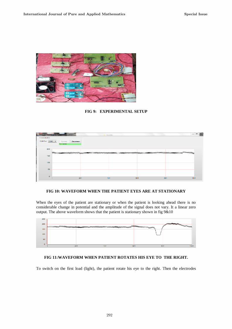
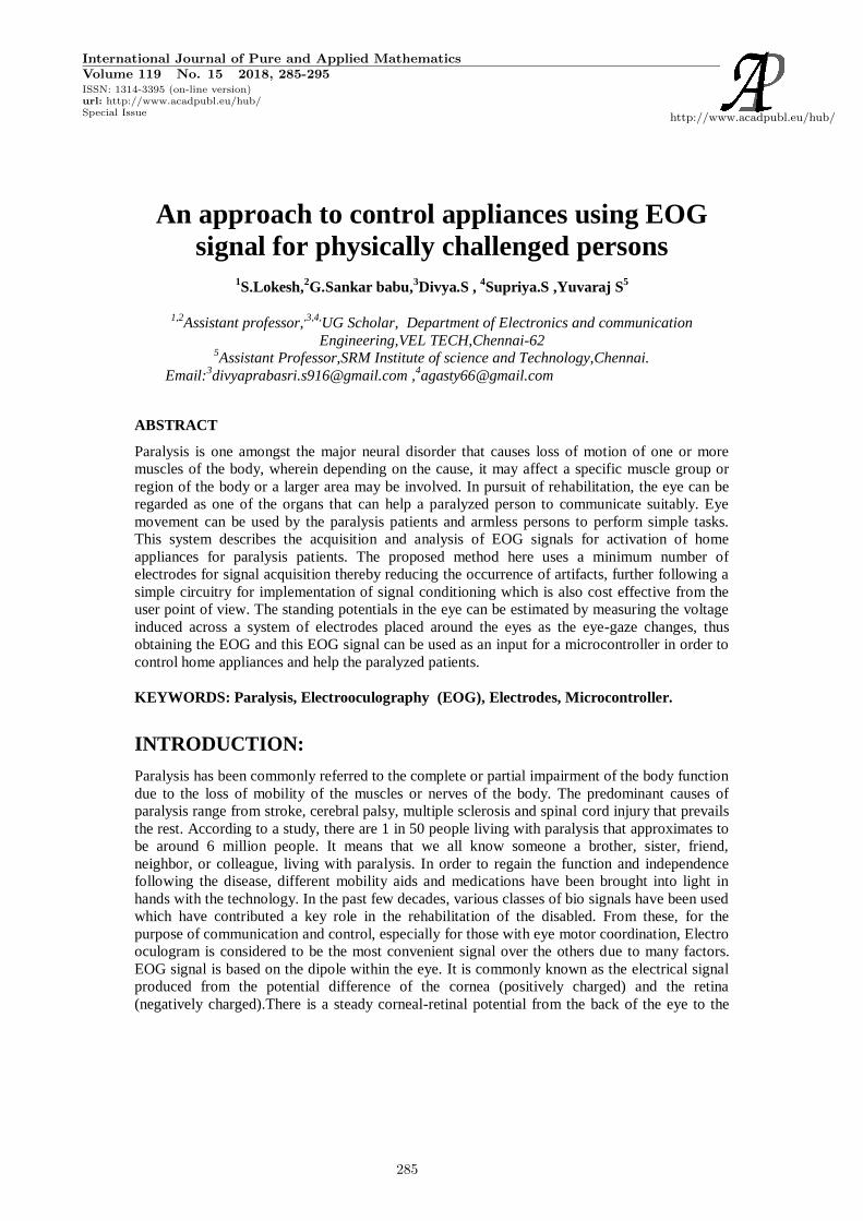
FIG 9: EXPERIMENTAL SETUP
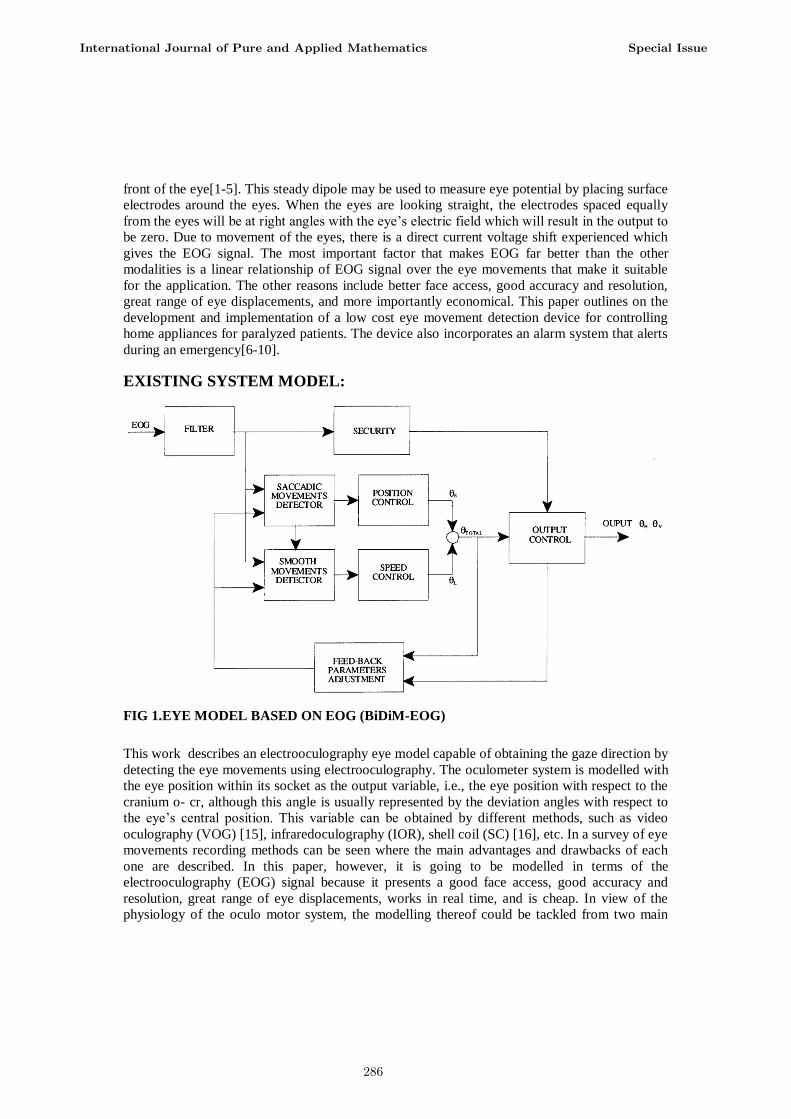
FIG 10: WAVEFORM WHEN THE PATIENT EYES ARE AT STATIONARY
When the eyes of the patient are stationary or when the patient is looking ahead there is no
considerable change in potential and the amplitude of the signal does not vary. It a linear zero
output. The above waveform shows that the patient is stationary shown in fig 9&10
FIG 11:WAVEFORM WHEN PATIENT ROTATES HIS EYE TO THE RIGHT.
To switch on the first load (light), the patient rotate his eye to the right. Then the electrodes
International Journal of Pure and Applied Mathematics Special Issue
292

gather the signal and the load is switched on. This waveform(fig 11) shows that the first load is
switched ON.
FIG 12:WAVEFORM WHEN PATIENT ROTATES HIS EYE TO THE LEFT
To switch on the second load (fan) the patient rotate his eye to the left. Then the electrodes
gather the signal and the load is switched on. This waveform shows that the second load is
switched ON shown in fig 12.
OUTPUT 4:
FIG 13:WAVEFORM WHEN PATIENT MOVE HIS EYES UPWARDS
To switch on the third load(dc motor) the patient move his eye to upwards. The electrodes will
pick the EOG signals and do the process for switch on the third load. This waveform shows that
the third load is switched ON shown infig 13
CONCLUSION:
International Journal of Pure and Applied Mathematics Special Issue
293

The eye movement based detection device for controlling home appliances has been proposed in
this system. The device is developed mainly for the paralyzed people, for whom mobility is a
point of concern. The device is based on the acquisition of EOG signal which is comparatively
inexpensive, efficient in terms of linear relationship of the signal over the eye movements that
makes it suitable for the application. The device here incorporates activation and deactivation of
appliances such as fan, bulb and door control. Towards the future, this method can be extended
to control other appliances like operating computers. Thus, using this EOG method the burden
for the paralyzed patients can be reduced.
REFERENCES:
[1] C.Reeve. Paralysis Facts and Figures-Spinal Cord InjuryParalysis Resource Center[Online].
Available:www.christopherreeve.org
[2] H. Harun, W. Mansor, “EOG Signal Detection for Home Appliances Activation”, 5th
International Colloquium on Signal Processing & Its Applications (CSPA), pp .195-197, 2009.
[3] P.S G , A. Govada , K. Swamy , “Eye Controlled Human Machine Interface (e-VISION)”,
International Journal of Advanced Research in Computer and Communication Engineering , vol.
2, May 2013.
[4] J.Jose, “Development of EOG Based Human Machine Interface Control System for
Motorized Wheelchair”, M.Tech thesis, Dept. Bio & Med Eng., NIT, Rourkela, June 2013.
[5] Y.S.Desai, “Natural Eye Movement & its application for paralyzed patients”, International
Journal of Engineering Trends and Technology, vol.3, April 2013.
[6] Dr.AntoBennet, M , Sankaranarayanan S, Ashokram S ,Dinesh Kumar T R,“Testing of Error
Containment Capability in can Network”, International Journal of Applied Engineering
Research, Volume 9, Number 19 (2014) pp. 6045-6054.
[7]Dr.AntoBennet, M, SankarBabu G, Natarajan S, “Reverse Room Techniques for Irreversible
Data Hiding”, Journal of Chemical and Pharmaceutical Sciences 08(03): 469-475, September
2015.
[8] Dr.AntoBennet, M ,Sankaranarayanan S, SankarBabu G, “ Performance & Analysis of
Effective Iris Recognition System Using Independent Component Analysis”, Journal of
Chemical and Pharmaceutical Sciences 08(03): 571-576, August 2015
[9] Dr. AntoBennet, M ,Sankaranarayanan S, SankarBabu G, “ Performance & Analysis of
Effective Iris Recognition System Using Independent Component Analysis”, Journal of
Chemical and Pharmaceutical Sciences 08(03): 571-576, August 2015.
[10] Dr. AntoBennet, M, Suresh R, Mohamed Sulaiman S, “Performance &analysis of
automated removal of head movement artifacts in EEG using brain computer interface”, Journal
of Chemical and Pharmaceutical Research 07(08): 291-299, August 2015.
.
International Journal of Pure and Applied Mathematics Special Issue
294

295

296