an approximate .analysis of open
TRANSCRIPT
AN APPROXIMATE .ANALYSIS OF OPEN
NONCIRCULAR CYLINDRICAL SHELLS
By
ASHO~ NAIN Ii
Bachelor of Engineering (Civil) Calcutta University
Ca],cutta, India 1904
Master of Science Illinois Institute of Technqlogy
Chicago, Illinois 1966
Submitteq. to the F1;tculty of the Graduate College of the
Oklahoma St~te University in partial fulfillment of
the requirements for the Degree of
DOCTOR OF PHILOSOPHY May, 1970

T\r'\o '::. ~ '., \ <\ '"l • :) -i..)
'{\J I c--:./1 c.
AN .APPROXIMATE ANALYSIS OF OPEN
NONCIRCULAR CYLINDRICAL SHELLS
Thesis Approved~
' ,.
ii
ACKNOWLEDGEMENTS
The author, on completing the final phase of his work
for the Doctor's Degree, wishes to express his indebtedness
and sincere appreciation to the following individuals and
organizations:
To Dr. Donald E. Boyd, for his sincere guidance in
the preparation of this thesis, for his instruction,
advice, and encouragement given throughout the author's
Doctoral program and for recommending him to teach as a
Graduate Assistant;
To members of his advisory committee Drs. T. s. Dean,
P. N. Eldred, R. K. Wunshi, and A. E. Salama for their
advice, understanding, guidance and suggestions;
To Mr. c. K. Panduranga Rao for his suggestions in
writing the computer program and also checking a portion
of the derivation;
To fellow graduate students in the Structures group
of the School of Civil Engineering for their friendship;
To the School of Civil Engineering, Oklahoma State
University and the Institute of International Education for
financial help;
To his parents for their love, understanding and
encouragement;
iii
To Mrs. Margaret Estes for typing the final manuscript;
To Mr. Eldon Hardy for his friendship, encouragement
and for preparing the·final sketches.
May, 1970
Stillwater, Oklahoma
iv
Ashok Nain
Chapter
I.
II.
III.
TABLE OF CONTENTS
Page
INTRODUCTION . . . . . . • • . . . . . . . . • • 1
1.1 Discussion. • • • • • • • • • • • 1 1 • 2 Background • • • • • • • • • • • • • • 2 1 • 3 Approach • • • • • • • • • • . • • • • 6
FORMULATION OF THE SOLU~ION • e • e e ~ G ~ 6 0 7
2.1 The Strain Energy Expression. • • • • 7 2. 2 Potential of External Loads • • • • • 10 2.3 Boundary Conditions • • • • • • • • • 12 2.4 Loads • • • • • • • • • • • • • • • • 17 2.5 The Total Potential Energy • • • • • • 18 2.6 Minimum of the Total Potential
Energy . . . . . . . . . . . . a • • 25
COMPUTER SOLUTION • • • • ~ • • • 0
3. 1 3.2
General • • • • • • • • • • • Discussion of the Programming
• • " 0
• •
Technique • • • • • • • • • • • .. •
IV. NUMERICAL RESULTS . . . . . . . . . • • $ 0
27
27
27
31
4.1 Convergence of the Solution • • • • • 31 4.2 Comparisons with Known Results
for Flat Plates. • • • • • • • • • • 34 4.3 Circular Shells • • • • • • • • • • • 34 4.4 Noncircular Shells. • • • • • • • . • 41 4.5 Accuracy of the Donnell Equations. • • 52
v. SUlVIlVIARY AND CONCLUSIONS . . . . . . . . . . ~ . 54
BIBLIOGRAPHY
5.1 Su,mmary • • • • • • • • • • • • • • • 54 5.2 Conclusions • • • •• ~ • • • • • 56 5.3 Suggestions for Further Work. • • • • 57
0 • a e e e O • e • e e e • • 0 • • e Q O 60
APPENDIX A - DERIVATION OF THE STRAIN ENERGY ExPRESSION -OF. A .NON:OIRCUL.I\R U:YLINDRICAL SHELµ • • • • 62
i . •
APPENDIX B - COMPU'l.'ER PROGRAM. 0 • • • • Ill • • • . . . 72
v
LIST OF TABLES
Table
I. Parameters for Various Boundary Conditions
II.
III.
IV.
Accuracy of Solution for Dif;ferent Values of k and p • . . . • . • • . • • " • .
Maximum Deflections for a Flat Plate for Different Boundary Conditions and Loads
Radial Deflection Comparison for a Simply Supported Open Woncircular Cylindrical Shell Under Uniform Radial Pressure with Lx/Ls = 4 and Differept L8/h Ratios ••
Page
16
32
• • 0 35
. . . 48
V. Circumferential Deflection Comparison for a Simply Supported Open Noncircular Cylindrical Shell Under Uniform Radial Pressure.with LxfLs = 4 and Different L
8/h Ratios. • • • • • • • • • • • • • • • • 49
VI. Radial Deflection Comparison for a Simply Supported Open Noncircular Cyltndrical Shell Under Uniform Radial Pressure with L8/h = 200 anq Different LxfLs Ratios. • • • 50
VII. Circumferential Deflection Comparison for a Simply Support~d Open Noncircular Cylindrical Shell Under Uniform Radial Pressure ~-.i th L/h = 200 and Different LxfL
8 Ratios • • • • • • • • • • • • • • • • 51
vi
L;rST OF FIGURES
Figure
1 • Shell Gepme try • • • • • • • • • • ~ • • • • • •
2. Shell Subjected to General ~oading in the Axial, Circumferential, and Radial Directions ••••••••••••••• • • 0
3. Line Load Applied Parallel to the Straight Edges in the Axial Direction •••••••
4. General Flow Chart for Computer Program ••
5. Convergence of Solution for Different Values
• •
of k and p for a Circular Shell • • • • • • •
6.
8.
Radial Deflections for a Simply Supported Circular Shell Under Uniform Pressure Loading •••••••••••••••••
Radial and Circumferential Deflections for a Simply Supported Circular Shell Under a Point Load Applied at the Geometric Center . . . 4 ~ • .., • • • • o Q • • • •
Simply Supported Circular Shell Under a Radial Sinusoidal Line Load ••••• • • 0 •
9. Vertical Displacements for a Simply Supported Circular Sl+ell Under a Radial Sinusoidal
Page
2
1 1
17
30
33
37
38
39
Line Load • • • • • • • • • • • • • • • • . • 40
10. Comparison of Displacements for a Noncircular Cylindrical, Shell Under Uniform Pressure and Different Boundary Conditions on the Straight Edges. • • • • • • • • • • • • • • • 42
11. Comparison of Dif;lplacements for a Noncircular Cylindrical Shell Under a Radially Directed Point Load at the Shell . .,Center and Different Boundary Conditions on the Straight Edges •••••••• o • • • • • • • 43
vii
Figure
12. Radial Deflections for a Simply Supported Open Noncircular Cylindrical Shell Under Uniform Radial Pressur~ with L /h = 100 and Different LxfLs Ratios, .s •••••
Page
• • • 44
13. Radial Deflections for a Simply Supported Open Noncircular Cylindrical Shell Under Unifo:111 Radial Pressure.with 1 6/h = 200 · and Different LxfLs Ratios. • • • • • • • • • 45
14. Radial and Circumferential l,)eflections for a Simply Supported Open Noncircu.lar Cylindrical Shell Under Uniform Radial Pressure with Ls/h = 200 and Lxf'Ls = 4. • • • 46
15.
16.
17.
18.
Radial Deflections for a Simply Supported Open Noncircular Cylindrical Shell Under Unifo:m Radial Pressure :with Ls/h = 800 and Different Lxf'Ls Ratios ••••••••
Sign Convention for Memqrane and lransverse Sn.ear Resultants • • • • • • • • • • • • •
Sign Convention for Bending and Twisting Moment Resultants ••••••••••
Sign Convention for Stresses on the Element
viii
• •
• •
• •
• •
47
64
64
65

A.,. l.
[~BJ, [CC], [DD]~ [ BC ] , [ BD] , [CD]
c
D
(D:J:SP]
E
G
h
i
... .,."'I" l., 11.,
K
le
'"9 ..,..,. J, JJ
NOMENCLATURE
ith COl'Jii:3ta.n,t for nondimensional curvature
i th cons·tant of. the series representing d:isp1ac1;1ment in axial., circumfer<:?ntiaJ., and· :radial directions, r~spectively
Matrices associated with coefficients of displacements bi only, ci only,
- di o:nly? bi ci, bi di and ci di~ respect1veiy
12(E) 2 { t Log [; : i] -1} 2r
Bending rigidity
Resultant Displacement Matrix
Hodulus of elasticity
Axial~ circumferential, and shear strain componente;, respe~ti-ye,.y
Axial, circumferential., and.shear strain components at median surface, re~pectively
Shear modulus
Thickness of shell
Index of summation
Indices associated with curvature constants
Eh 1-v2
Number of terms less one necessary to express the curvature
ix

m
-n, n
M Tl ' M ~ , Mx , Ms
MTls' M~ll' Mxs' Msx
NT!, NS, Nx, Ns
NTI~' Nsll' Nxs' Nsx
Px' Py, P 2
p
Qx' Qs ·
qx' qy, qz
r
s' x, z
u, v, w
u
v
XL' YL, z . L
[X]
(Y]
Number of terms less cne in the displacement function along the curved edge of the shell
Length of the shell in x- andsdirections
Index o;f displacement si.unmation along straight edges of t4e shei1
Indices of displacement summation along curved edges of th~ shell
Bending moment resultants
Twisting moment resultants
Membrane stress resultants
Shearing stress resultants
Paint load on the shell s~rface in axial, circu.mferential, 8l'1d radial direction, respectively
Number of terms ip the displacement function along the straight edges of the shell
Tranf:iverse shear stress resultants
Total line load on shell surface in axial, circ;urnferential, cmd radial di;r·ection, respectively
Radius of curvature
Spatial coordinates
Displacements in x, s, and z direction, respectively
Strain energy in the shell
Potential of external loads
Load per unit area of shell surface in axial, circumferential, and radial direction, respectively
Resultant strain energy matrix
Resultant load m~trix
x
a., s, v, 6, .n.,. e, t
c
11, I;
\I -11
p
Po
1xs' 'T'sx
Constants defining the boundary c9nditions on the straight ed~es
Noncirc;rular:i, ty parameter
No~~imensional x ands coordinates x s r;-,r x s
Axial and circumferential curvature changes and twist of element of median surface of shell, respectively
Poisson's ratio
Total Potential Energy
Nondimensional radius of curvature
Uniform pressure per unit area
Normal stresses
Shearing stresses
Median surface rotations
Summation
xi
1o1 Discussion
CHAPTER I
INTRODUCTION
As a result of considerable technical development~
cylindrical shells find wide industrial application in the
design of certain class of structures" A problem encountered
by the structural engineer is to find the stresses and dis
placements in a noncircular cylindrical shell subjected to
arbitrary loading and restrained in some manner along its
boundarieso Practical cases of this problem include open
shell roofs, submarine hulls an.d aircraft structureso
Furthermore~ non.circularity of the cross section may be
.introduced during construction of circular cylindrical ,
shell so
It is well-known that the classical~ exact methods of
.:sma1ytieal solution cannot be applied to the above problem
with the desired degree of generality and that approximate
techniques mus·t be used to obtain answers to realistic
problemso
It was the objective of this research to study~ using
the energy principles and approximate methods 9 the dis
placements in an open non.circular cylindrical shell where
the curvature can be expressed as a power series ..
1
2
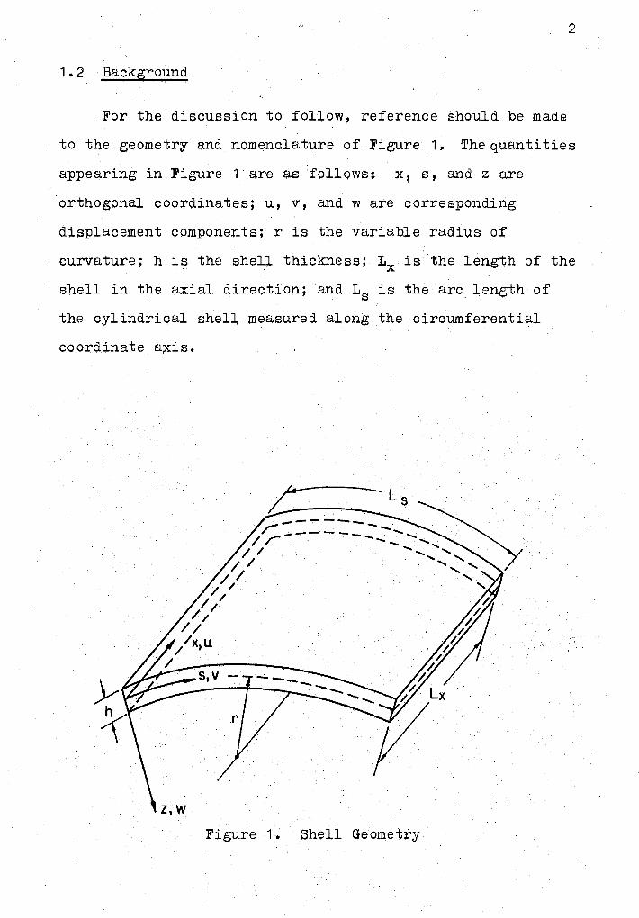
1.2 Back&round
For t~e discussion to follow, reference should be made
to the geometry and nomenclatu;re of Figure 1. The quantities
appe~ring in Figure 1 are as follows: x, s, and z are
orthogonal coordinates; u, v, and ware corresponding
displacement components; r is the variable radi~s of
curvature; h is the snell thickne:;3s; Lx is the length of .the
shell in the axial direction; and Ls is the arc length of
the cylindrical shell measured along the circumferential
coordinate a;x:is.
Figure 1. Shell Geometry
A number of analyses have been performed on circular
cylindrical.. shell structureso These are discussed in any
classical text on shells (eo io, books by Flugge (1) 9
Timoshenko and Woinowsky-Krieger (2) 9 Harry Xra ... s (3) or
Lundgren (4))o Relatively little work has been done on
noncircular cylinderso
3
Probabil.y the first attempt to solve noncircular
cyl.indrical shell problems was made by Tim.oshenko.,. Lundgren
too solved shell problem.e for ·a few specific noncircul.ar
cases., Kempner and his associates (5) and (6) performed a
series of investigations into a class of closed oval
cylinders having a variable radius of curvature used by
Marguerre (7), which contains en "eccentricity" parametero
This curvature expression is given by equation 1o1a That is,
where
1 1 [· ; (4ttsl] r = r O 1 + s cos ,;; ( 1 0 1)
r = local radius of curvature of cross section;
r 0 = radius of a circle whose cir~umference is equal
to that of the oval (L0 ), ioe" 9 L0
= 2nr0
;
s = parameter measuring eccentricity of the oval and
obeying the inequal.i ty 1' I 5 1 o
Kempner's approach has basic limitations in that the
curvature expression contains only one "degree of freedomn
(io.eo P the eccentricity parameter) and consequently it
cannot be applied to any sufficiently general shell
segmento
4
Boyd ( 8) expressed the curvature in general nondimensional
parameters as a finite power series. This expression is k
l AI sI 1 ( 1. 2)
p where l:;::0
1 ..., p
= nondimensional shell curva tu.re, wh;i.ch is related to
the actual shell curvature ; by tpe relation p:;:: f ; s s = r;
s A~= unitless constants dependent upon i
l
k :;:: number of terms necessary to express accurately
the curvature.
The curvature series can be obtained for any general
cross section using a suitable best-fit technique such as
Lagrange interpolation or the least-square method (9).
For the special case of a circular cross-section with
a constant radius, equation 1.2 reduces to
1
Another special case of equation 1.2 is the flat plate
for which all AI are identically· zero. Physically, this
represents the case of an infinite radius of curvature.
In his paper Boyd used Donnell equations 1 to solve the
1Donnell (10), in 1933, derived a simplified set of equilibrium. equations for circular cylinders. In deriving this set of equations, Do:nnell ~ade two simplifying assumptions. He first assumed that the transverse shear force makes a negligible contribution to the equilibrium of forces in the circumferential direction. As the ratio of the radius to the thickness of the shell increases. this assumption can be expected to :i,mprove in accuracy (3). In aq.dition, he assumed that the circumferential. displacements result in negligible contributions to the changes in the curvature and twist.
-.kl (J
~ ~
0
°' 0\ -I N N
0::: Cl-c:x:
5
nonciroular cylindrical shell simply
3 curved edges. He assumed the displace
in the form of a doubly infinite series;
ries in the x-direction and a power series 0 r,,..
°' , and reduced the set of partial differ
o a set of three recurrence formulas •
.....
• ~ .. nee formulas and the eight equations c !I -- ry conditions along the straight edges,
vual. displacements in the shell segment were calculat_ed.
hP method of Boyd, however, has some basic limitation&
- - -- .....,
curv-a ture ;
Jl 0 it was applied to Donnell-type equations,
,r short shells with large radii of
2. !ince the loading function must be expanded as a
Pourier aeries, it is difficult to take into account any
general loading function;
3. though theoretically possible to solve any
problem, it sometimes becomes impractical to solve_ problems
where convergence of the assumed power series does not occur
after taking into account a limited number of terms.
The purpose of this thesis, which is the enenstc,n o·f
the ideas expressed by Boyd in his work, is to find an
approximate solution which .would satisfactorily overcome
· some of the above limitations and hopefully provide a more
realistic approach to the problem.
1 • 3 Approach
Instead of following Boyd's approach of using the
governing differential equations and Dor:µ1ell's simplified
assumptions, the principle of stationary potential energy
of the system is used.
6
The energy method used here, commonly known as the
Rayleigh-Ritz method, is an approximate procedure by which a
continuous system with an infinite number of degrees of
freedom is reduced to a system with a finite number of
degrees of freedom. The method is based on the principle
of stationary potential energy; i.e., "of all displacements
satisfying the given boundary conditions those which satisfy
the equilibrium equations make the total potential energy
stationary." In this method the independent parameters of
the assumed displacement functions are determined by
minimizing the total potential energy with respect to each
of these independent parameters.
One important feature of the above method is that the
assumed trial function for displacements need not satisfy
all boundary conditions, but only the II essential" (i.e.,
"displacement") boundary conditions. The additional 11 natural"
(i.e., "force") boundary conditions are automatically
satisfied simultaneously with the equilibrium equations
through the use of .the principle of stationary potential
energy. AA extensive discussion of some of the :;ubtlcties
of this method is given in books by Oden (11), Kantorovich
and Krylov (12), and Langhaar (13).
CHAPTEH II
FORMULATION OF THE SOLUTION
2.1 The Strain Ener~;x: Ex;eression
The expression for strain energy U ( equation 2, '/) for a
noncircular cylindrica,l shell is given by Kempner ( ~), Ii'or com
pleteness a ,Jummary )f the derivation is given :in Appendix A.
Eh ~ ~ ~ 2 [ /~2 u = ' . . ( u ' ) + v ' - \!i. + 2(1-\)2) S X X. S r
[v, 6 (;)] + (i)(1 - \))(u,s +
lw2) - C}H2
+ 2 \) w'xx [w'ss
+ (~)v, s - ())v J + ( 1 - v) ~ [w•xs - (;) u, Sr + (~) v,~
2 + (~) w,xx u,x})dx ds
~ 2. 1)
+ (i) (1 - v) [w•xs
where the subscripts followil'lg a comma indicate differen-
tiation. From Figure 1
~, s, z = longitudinal, circumferential, and radial .,
coordinates, respectively;
u, v, w = displacements in the x, s, and z directionsf
respectively;
r = variable radius of cu.rvature;
\)=Poisson's ratio;
7
h = shell thickness (asswned constant);
E = Young• s modulus of elasticity;
c = 12 (T;)2 { f Log [] : ~ ~~]- 1 }
3 (h)2 3 (h) 4
= 1 +20 r +112 r + •••
c represents a rapidly converging power series in terms of
the ratio ~· Since the thickness of the shell is assun1ed
to be very small compared to the radius of curvature, all
d d d h . h of h b 1 t. , d secon or er a,n ig er powers r can e neg ec ea &'1. c
then becomes equal to unity.
Equation 2.1 may be written in nondimensional form by
using the following nondimensional ~arameters;
Tj x = ~
g s = t;
r p = 1 s 25
Eh Lx L8 1
~1 u ~ I u. d!; dTj - 2 l 2(1-\)) Tj=O !;=0 i= 1
(2o3)
where
U1 1 (u, Tl) 2 =
L 2 4
1 2 U2 = ~ ( v' s)
Ls
U3 1
(~)2 = L 2
s
U4 2
(v' s) (;) = - L 2 s
U5 2 \)
(u,Tj)(v,s) = LXLS
Q 'J
U7 = ( 1 - v) 2 L 2
s
Ug = ( 1 - v) 2 1 2
x
= h2
12 1 4 s
h2
= 12 L 4 s
(u,l;)(v,T})
(w,llll)2
2
U14 = 6\84 (w,~~)(-~)
U15 =-/:8
4 (~)(p,~) (7)
u16 =-6h:84 (w,g~)(p,gl(j)
h 2 \)
U18 = 6 L 2 1 2 x s
h2 \)
( w. ) ..:!. ( ) ··''flTI p v,I;
9.

10
2 U20
h ( 1 - v) 2 = 6 L 2 L 2 (w,Tls)
x s
U21 h 2 (1-v} 2 Cf ;::
24 L 4 (u' s) p s
2 (w '11;) (u is)(~) U22 = h ( 1 - v)
12 L L 3 x s
2 2 (1) 2 U23 = h ( 1 - v l
(v 'Tl) P 8 L 2 L 2
x s
2
(i) U24 = h ( 1 - v) (w 'Tis) (v, il)
4 L 2 L 2 x s
U25 h2 (l) (w 'T]il) (u, T]) (2.4) = 3 6 Lx Ls
2.2 Potential of External Loads
In keeping with the basic K~rchhoff-Love assumptions
of the· classical theory of thin shells, all applied loads
are considered to remain f;i.xed in <5.irection and magnitude
during any deformation of the shell. Thus, with reference
to Figure 2, the potential of surface loads is
V = - s s ( X1 u + YL v + z1 w) d s dx L Ls
x
(2.5)
where Xii, YL, and z1 are the surface loads per unit area of
the shell surface applied in the axial, circumferential, and
radial directions, respectively.
Introducing the nondimensional form of equation 2.2
into equation 2.5 we obtain
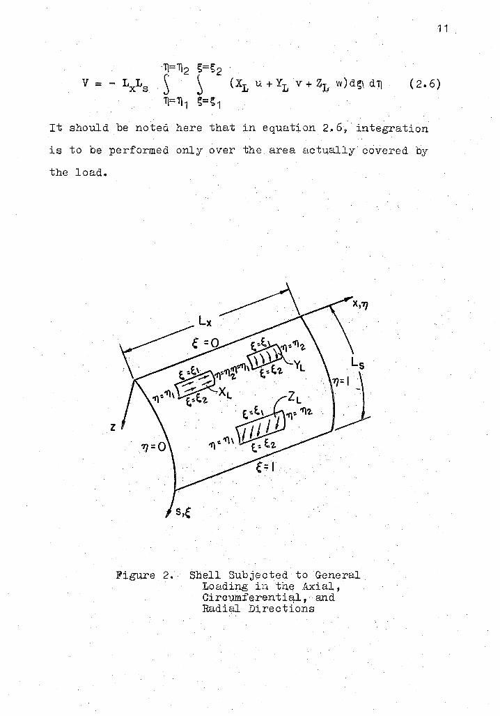
11
Tl=Tl2 g=g2 .
V = - LXLS .s S (XL u+Yr, V+4:r, w)dg\dTj ( 2. 6)
Tl= Tl 1 g::; g 1
It should be noted here tb,at in equation 2.6, integration
is to be performed only over the area act~allycovered by
the load.
z
~ Lx . .
Figure 2. Shell Subjected to General Loading in tl).e Axial, Circv.mferential, and Radial D:Lrections

12
2.3 Boundarl Conditions
An examination of the prObl~m reveals that sixteen
independent boundary conditions are needed for oomplete
solution of the problem, tbere.being four along each of the
four edges. In the metbod used here, as stated earlier,
only the displacement bo~ndary condition~ need to be
satisfied along each e\lge, the naturgl boundary conditions
being automatically satisfied. In general, the boundary
conditions to be satisfied are:
u = 0 or N !;T} = 0
v :;: 0 or Ns = 0 i:tlong s = o, 1 (2.7)
w = 0 or vs = 0
~!; = 0 or M~ = 0
and
u = 0 or N,q = 0
v = 0 or NTls = 0 along ll = o, 1 (2.8)
w = 0 or v = 0 T}
~T} = 0 or MT} = 0
where
N !;11 N Tl!; = Shear stre.ss resultant
N !; NTl = Normal s.tress resultant
vs VT} = Effective transverse e;;hear rosultant
~!; ~T} = Slope of the normal to the mi,dp:l e surface
M~ MT} = Moment stress resultant.
Reference should be made to Appendix A for the notations
used above.

13
For the problem here it is as$umed that the bour;i.dary
conditions along the curved edges always remain the same,
i.e., at 11 = O and 1, v:::; O, vv = O, N11
= O, and M11
= o.
This is the case of simply supported edges which ape free
to move in the axial direction but not in the other two
directions. It is necessary to satisfy only v ;:;: 0 and w
at Tj = 0 and 1 • Consequently, u, v' and w are assumed in
the following form:
p
u ::;: I furn(!;) COS mTTT\
m=1
p
-
v = l fvm( !; ) sin mnT} (2@9) m=1
p
w :;:: l f Wlli ( S) sin mrrTj
m=1
where furn, fvm, and fwm are undetermined functions of s• However, the other two co~ditions NT\= 0 and MT\= 0 along
the curved edges Tj = 0 and 1, are also satisfied.
The boundary conditions along the straight edges
(!; = 0 and 1) expressed in termi3 of displacements an,d non
dimensional coordinates, are given in reference (14) by
equation 2~10
N!;T\ - .@! [Ls - Ls Lx v' T\ + u, s]
N !; K [ Ls +v(~s)u,~J (2.10) = Ls v, S + r w
. x
L 2 J vs = - D3 [w'gS + (2 - v)(1:) w,T\T\s
Ls
0
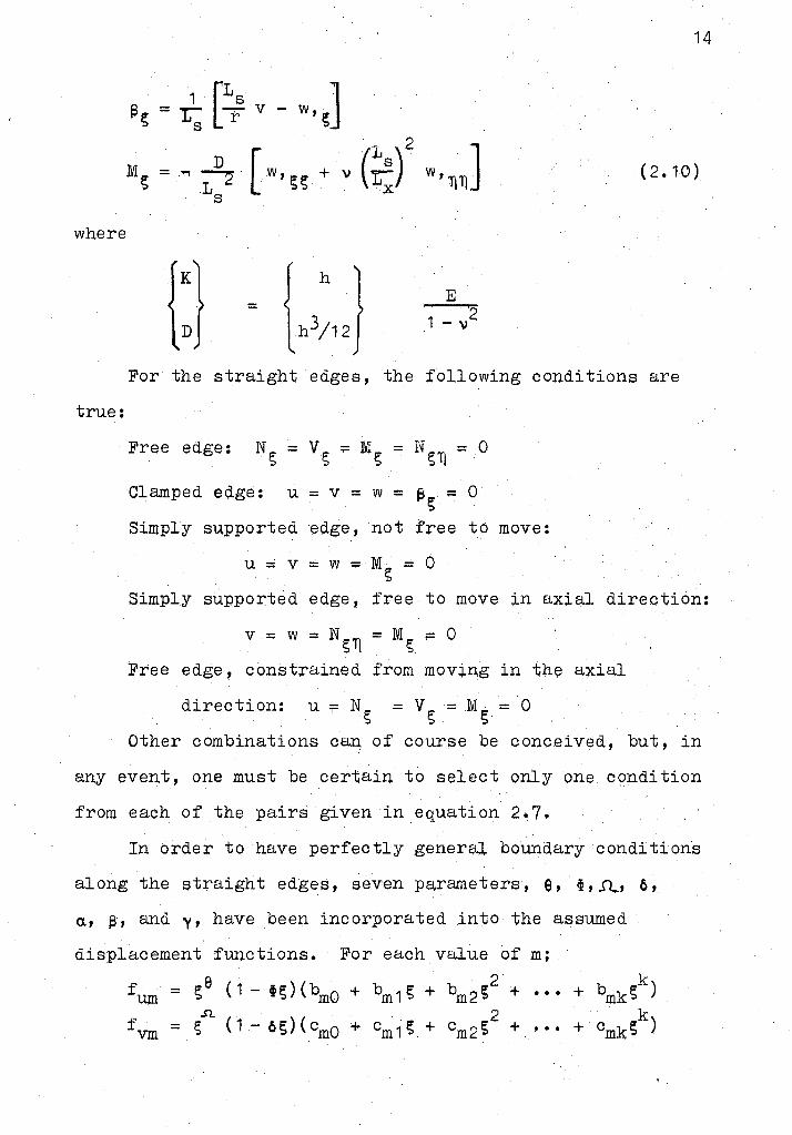
14
(2.10)
where
{:) = E
2 1 - "
For the straight edges, the following conditions are
true:
Clamped edge: u = v = w = 13 - 0 !; -
Simply supported edge, not free to moyE:l:
u - v = w =· M = 0 s Simply supported eqge, free to move ;in ax;i.al direction:
v = w = Ns'Tl = Ms ,..... 0
Free edge, constrained from moving ip thE:l a:xial
direction: u r NS =Vs= M; = 0
Other combinations can of course be conceived, but, in
any event, one must be certain to select only one condition
from each of the pairs given in equation 2.7,
In order to have perfectly general boundary conditions
along the straight edges, seven parameter$, e, ~,.rt., 6,
a., ~' and y, have been incorporated into the assuml;:ld
displacement functions. For each value of m;
fum i; e ( 1 - t !; ) ( bmo + bm1 S + 2 k = bm2 !; + . . . + bmks )
.n. ( 1 - 6;) ( cmo +
2 k fvm = s cm 1; + cm2!; + ••• + cmk!; )
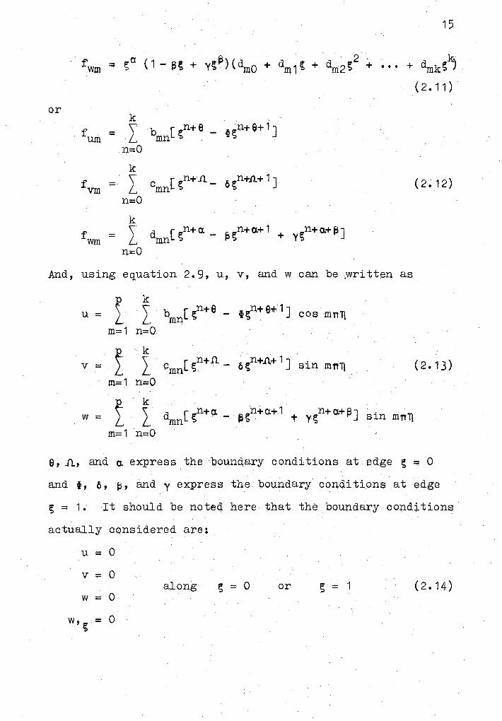
or
n=O
k fvm = l cmn[sn+11_ 6gn+.n.+1]
n=O
k fwm = l dmn[ gn+a. - f)sn+a.+ 1 + ygn+a.+l:l]
n=O
And, using equation 2.9, u, v, and w can be .,written as
p k u:::;: \ l b [gn+e - 1~n+ e+1 J cos ffiTil\ L m:ri
m=1 n=O
p k v = l I cmn[ gn+.O. - 6~n+..o.+ 1 J sin mnl}
m=1 n=O
p k w = l l, dmn[ gn+a. - ~gn+a.+1 t ygn+a.+Fl] sin mnl}
m=1 n=O
15
(2.12)
(2.13)
e, 11, and a. ex~ress the boun~~ry conditions at edge g = 0
and i, 6, f3, and y e:;icpress the "boundary conditions at edge
g = 1. It should be noteq. here that the boundary conditions
actually cqnsidered are:
u = 0
v = 0 along !; = 0
w = 0 or g = 1 (2.14)
= 0

For the various boundary conditions stated earlier
the values of the para.meters e,..n, a. and w, ~' ~' y are
shown in Table I.
TABLE I
PAR.A.METERS FOR VARIOUS BOUNDARY CONDITIONS
BOUNDARY CONDITIONS
Free
Clamped
Simply supported, not free to move
Simply supported, free to move in axial direction
Free, constrained from movin& in the axial direction
e
0
1
1
0
1
Conditions along ;=0
11
0
1
1
1
0
a.
0 0
2 1
1 1
1 0
0 1
Conditions along s = 1
0 0
1 2
1 1
1 1
0 0
With the nelp of the above table, any boundary
conditions can be introdµced along the straight edges.
y
0
1
0
0
0
Other boundary conditions can also be treated by choosi~g
the appropriate values of the parameters.
16
17
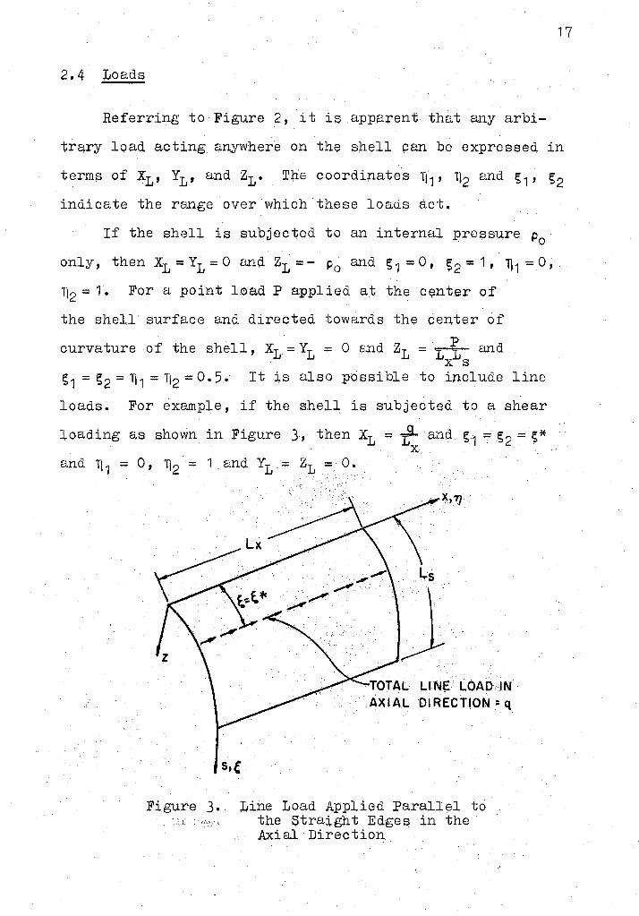
2.4 Loads
Referring to Figure 2, it is appa+ent that any arbi-
trary load acti,ng anywhere on th~ spell can be expressed in
terms of XL, Y1 , ~nd z1 • Tlie coordi;nates 11 1 , 112 ano. s1 , s2 indicate the renge over wl').ich these loads act.
If the shell is subjected to an internal pressure p0
only, then x1 = Y1 = 0 and z1 = - p0 and s 1 = 0, s2 = 1, 1) 1 = 0,
1}2 = 1. For a point l.c,ad P applied at the qmter of
the shell surface and directed towards the center of ·. p
curvature of the shell, x1 = Y1 = 0 snd z1 = t=t": and x s
s1 = s2 = 1} 1 = 1J2 = O. 5. It is also possible to include line
loads. For example, if the shell is subjected to a shear
loading as shown in Fig1+re · J, then x1 = y;- and s1 = .s 2 = s* X.
·.~s .·
.}··· ... ·· ... · . . .
. . .
LI NE. LOAD IN AXIAL DIRECTION= q
Figure J. I,iipe Load Applied Parallel to , "':'::, the Straight Edges in the
.Mial•Direction
Similarly other line loads, either in the s 'or z
direction or line loads parallel to the other major axis
of the shell can be prescribed.
It is also possible to consider any combination of ·
loadings which may result on reso+ving a pi;l.rticular load
in its components along the principql direct~ons of the
shell.
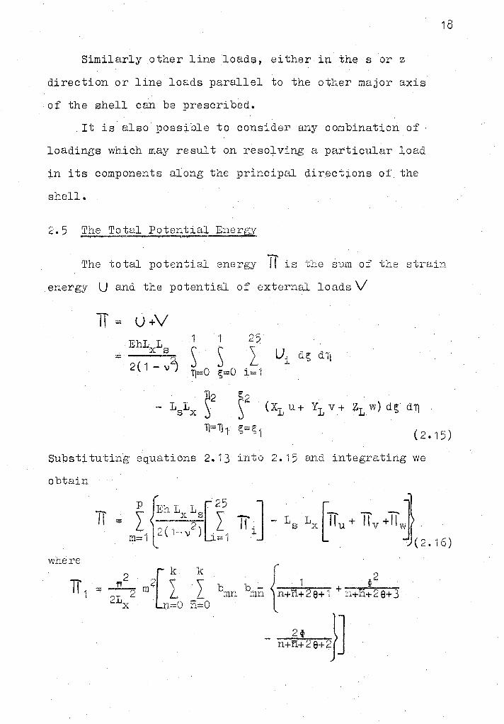
2.5 The Total Potential Energy +=¥ I
18
The total potential energy iT is the sum of the strain
. energy U and the potential of external loads V
lT = u +V ·EhL L x s
= ----2 2(1-v)
25 \ L
i=1
Subst;i. tlJting equations 2. 13 into 2. 15 a.;nd integrating we
obtain
where
P (Eh L L . [2
5 . J . [ . J} TI = l (~ ~-.. 22 s • L TI .. - Ls Lx ~.llu + llv +lTw IC.:.\!"''\))..; :i
m= 1 \,. :::: 1 . ( 2 • 1 6 )
b mn {
1 . ~2 bmn n+ti.+2 e+ l + n+n+29+ 3
2t l] - n+n+29+2J

19
c -{i.12::t..Jl)(n+.Q)__ + .,o2
(n+Jl+"l)(n+Jl+1) 0mn mn n+n+2Jl.-1 n+ri.+2.a.+ 1 .
_ ..§.c(u,+.n.) (~-t,11.+ 1 )+(n+Jl+ 1) (ii+n.~.n n+n+21l U
lT 3 = ~ [ I J J J dmn dmn AI AJ {ri+i'l+th+20.+ 1 + s n::;:0 ne:0 J.:;:i:0 . J;:.:0
--- e2 + --....:t-~- ·- ·--1.fL..~ n+n+I+j+2Q..+3 n+fi+I+·j+2a.+2f:1+ 1 n+n+I+"j+2a.+2
+ 'ii+l'lJ;j+~a+Jj+"'i - n+n+!~}].
k k k { TI --1- L ~· v \ c d - A...- ( n::11) . 4 - 1 2 L _,L_ _L . mn mn i n+n+ i+ a,+.11
s n=O n=O i=sQ
TI 5
_ · 6.(n+£b_+ 1 L. _ _ J.,JE.±-.E)__ ~ ~6 (n+11+ -1) n+n+I+a.+11+ 1 n+n+I+ a.+.a+ 1 + n+n+I+a.+.n+ 2
·t ~(n+Jl) __ ·- ~n-}J n+n+I+a.+Jl+ is n+n+I+a+n+ f3+ 1
lr k { = - ~.IL m [ '\ \ b -c ~ (n+4L + "~ri+.a+Jl
L L L /_, mn mn n+n+ 0+11 n+n+ a+.11+ 2 x s .., n=O n;;O
k k \ \ _l L
Ur::;0 1=0
_ 11.~:t1~)t_. 6 (ntn+ 11}1 n+n+ e+.n + 1 J
d ,-; A.,,. {--· ---1,;_-mn + P.+i'l+ i+ o.+ e+ ·1
§ + ~ ---..' J. __ _ I I --,.~--·• ......... - - --- _ --,
n+n+I+a.+0+2 · n+n+i+a:+9+f>+1 n+n+I+a.+e+2
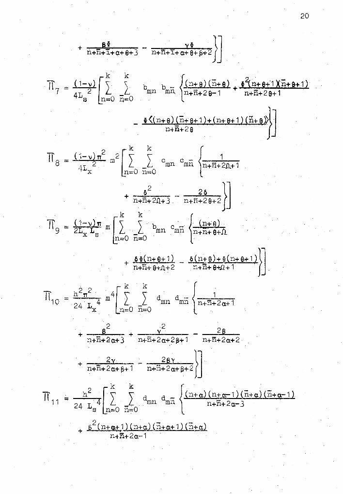
20
B~ _ · Vi }J + n+n+'f+a.+0+3 n+n+l+a.+9+~+2
k k { TI7 = ( 1-\1)[ \ 'L bmn b - ln+.eJ (n+e) + t~n+e+1 Xri+e+ 1) ~ L mn n+n+20-1 n+n+2e+1 · s n=O n.=0
- f((n+e)1n+e+l)+(n+e+1) (n+~»lJ n-+n+2 0 f
..,....,.,, c-1-\l)rr2 2[Ik Ik c c - { . 1 8 = -· '2 m L1L .••. ~ mn mn n+n+2.n.+1
r x n=O n:::0
+ n+:~211+3 - n+n!~e+2 }]
lT = < 1 ~ \)) n . · ~ ~ ~ b c { ui+_e1 · 9 2LX-LS m L _L .. mn mn n+n+e+Ii.
n:;;0 n:::0
+ +6~(n+e+1) _ 6(n,!6)+9?(n+er+-1,)}l n+n+ 0+1l.+2 . n+n+ e+Jl+ 1 J ..
d~n {-n-+_,.n,-;1-2-a:_+_l
+ -,· 82 - + - y2 - - 28 -n+n+2a.+ 3 n+n+2a.+2 ~+ 1 n+n+2a.+2
+ . 2y _ ;_ _ 2BL-}J n+n+2a.+i,+1 n+n+2a.+f;+2
= 1-i2. [ ~ .~ d d _ {Cn+a.) <n+a.-1, Ln+a.) (n+.a.- ·1) 24 L 4 l ~L mn mn n+n+2a.-3
s n=O n=O
+ ..s 2 (n+a.+ !l (n+a.)Jp.,ta.+ 1 )(n+g.l_
n+fi+2a.·~ 1
+ y2
(n+a+s) (n+a.+ s-1) (ri+a.+ s) (,n+q+ s-1) n+n+2a.+2 ~..,. 3
21
_ s<<n+a.) cn+a-1) cn+a+11n+a)+<n+q)(n+CJ:"!.1) w,+a.+1) Cn+aV - ' ' 'I' I I .
n+n+2a.-2 · ·
+ y ((n+a) (n+a.-1) (n+a.+s) (n+o.+s-1}) n+n+2a.+13-J ·
+ )'.\Cri+a.) 'n+a.-1) (n+a.+s) (n+o.+s-1 ~ ·· n+n.+20,+13-3 .
_ sy(<n+a+ 1) (n+g) (n+g+B) (n+a+s,..1)) n+n+2a.+~-2
1
·
2 [k k k k k k 111 2 = 2 hL 4 l _l _L -~ _l _l dmn .drnn Ai
4 s n::::O n=O i=O j=O ii=O j j=O
{ 1 ---· _s2~-
n+ri+'i+J+II+'Jj'+2a+1 + n+n+i+J+"il+JJ+2a+3
2 + --------~·----~--- -----~2_s ___ __,.. __ _...._
~+n+!+J+ll+JJ+2a+2~+1 ~ n+n+l+J+l1+J~+2o.+2
A.., A-.--.- A'""""' J :l.l JJ
2y + =· ··-' --
_ · 2Sy ~l n+n+1+J+II+JJ+2a+~+2 Jj n+ri+l+ J+11+ J J+2a.+13+ 1
22
n+a n+a.+ 1 J =- ....,. • --,. + = ~· -=" .... + _ ..,; _ . {
-· ) (.... ., ~ ·1 . . I::, y ~ · n+11+1+J+2a.·-·1 n+n+i+J+2a, n+n+i+J+2a.+~-
- n+ a.+ 1 n+ a. . _ _ ~ ..... -- __ _ . . . + ----=-- _ . .,_... (- ) c- )·~ 1 · 6 . · ~ i> ~ +n+1.+J+2cx. n+n+1.+J+2o:+ 1 · n+n+i+J+:2a.+
+ n+ + (n+a.+ -1 --~---- - __ ~- ,a.·-( - ) . ..,. )~ ·1 ~ 'Y (l ~ ~ 11.+li.+i+J+~!o.+ 13-1 n+n+i+ ;j+2a+ f3
2 ~k 1T ·- _£__ \ 1 5 - ·1 2 L s4 n~O
k
{ 1 -- ~-
n+n+I+'j+I!+a.+Jl+ 1 n+n+I+:j+Ii+a.+Jl.+2
+ - ..Y..., _____ - __ _____§_ __
l'H-.n+I+j'+Ir+a.+Jl+~+ 'f n+n+i+J+!i+a.+11+2
+ n+n+i+J+!T+o.+.D~3 --~ ... ~~-...... 6 }] n+ii+I+;f +II+o.+.fl+ p+2
i:;·::()
23
k k
-- h 2
v n2
2 l \ \ I L17 = - 2 2 m l L dmn dmn 12 1x 1 s n=O n=O
fcn+oJ (n+a-1) /- 1 - - B · + y __ '\ t '\_n+n+2a. ..... 1 n+n+2a. n+n+2a+s-v
- S (n+a+ 1) (n+aJ/- .1 - ~ + Y ---) '\n+n+2a n+n+2o.+1 n+n+2a+l3
+ y(n+a+s) (n+o.+s-1)/_ ·- ; 1 - :: ~ + -· ·/L.? ~1Jl . ~+n+ a+ s... n+n+ a+ s n+n+ o:+'"'- s-rJJ
Lk k k { 2 ~ · • (n±)
m o d - A- - ~a L J, J mn mn i · n+n+i+a.+Jl n=O n=O i=O
. ~
_ ~n!n+1) _--J.i[:+n) +· eoJ~+n+1}_ n+n+i+a+n+1 n+n+i+a+n+1 n+n+i+a+n+2
+ _ y{n+Jl) ~ _ oy(n+il+ 1) }J n+n+I+a+.1l+f:l n+n+I+a.+n+f:!+1
,_ 2 2 "[k k k { I I = ::- . h v TT •· m c:. \ \ \ c d - A..,. I -....-..,,2---19 12 L 2 1 2 _ L .,...L ..,.L mn mn 1 n+n+i+o:+11+1
x s n:::::0 n==O 1=0
... __ __j3 __ + -- Y.. ·---· - --.......... 6 __ :n+n+I+a.+Jl+2 n+n+I+a.+n+ 13+ ·1 n+n+I+a+fl+2
+ -~--6 6 -- _ -~·-=~}] n+n+I+a+.12+3 n+n+i+a+fl+S+2
h2{1~-v1,,2 2[Ik I~ , d {fn+a).cn+a} = ~ ~--- m a - ..},:,;; - - !!L 'I 2 L 2 L 2 .. - . - mn mn n+n+ 2 a-1
x s r1=0 n=O
+ l~~llt~JQ}+cxj-1) + _y2(~+.]){n+g+6) n+n+ 2 o:+ 1 n+n+ 2 a+ 2 s-1
_ JLS.(n+a.Hn-1: a+ n + Jn,,,:ta+ n (n+,cx» . n+n+2a
+ y((n+a) (n+o:+s) + (n+a:+s) (n+a,)} n+r.i.+2 o:.+ t3-1
_ SY<(n+n+1) ~ii+n+S) + (n+n+sl(ii+n+1 )~lJ n+n+2a+~ f
24
~ k k k k f Ii == h~( ·i-v) [\ \ \ \ b b - Aw- A-. (:_:+~) 5.n+e) 2·1 48 1 4 .L .L. ...,.L ..,L mn mn i J n+n+i+J+2e-·1
s i=O J=O i=O J=O
+ 1p2~n+J+1)(.j+e+1l _ w<(n+e)(j+e+1) + (
1n+e+1)~j+e))},l
n+n+I+J+28+1 n+n+I+J+28 j
d - .A- f.U2-+ el ( n+ cx.) mn i ln+n+i+cx.+9+1
_ 12 ( n+ e) ( n + Cl+ 1 )
n+n+I+cx.+e+2 .l'.'..in+e)(ri.+a.+s) _ ~(n+e+1)(n+cx.)
+ - -· - ...,·. . ' n+n+i+o.+ e+ ~+ 1 n+n+i+a.+ e
+ ].__tin+e+1) (n+a.+1) _ ~y(n::e::1) (n+o.+s)}J . n+fi+!+ a+ e+ 1 n+n+ l+ a+ e+ ~
2 2 k k k k = h.J-1=~) TT . m2 (\ \ \ \
-5 1 ~ L 2 L l L L I x s n=O n=O I=O J=O
c c -{-1...,......,,... mn mn n+n+i+j+2fl+1
d - A~ { (n+a.) cmn mn l n+n+I+cx.+n
= .. s(§+a+n_ + . y(n+a+s) _ 6(n+o) 11.+nt-l+t.,.+Jl.+ 1 n+n+'i+ cx.+n. + ~ n+n+i+ a;-1-Sl+ 1
+ 1:i s(n+o.+ 1) _ §.Y(ri+a+e) }] n+n+i+ a+.n.+2 n+n+I+ a.+.Q+ t3+ 1
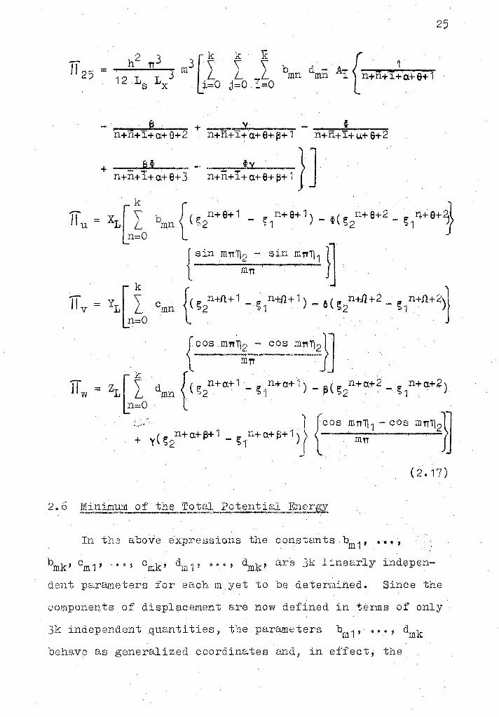
25
2 TTJ mtt k le - h \ \
{ 1 11 25 = 3 L _L bmn dmii Ai 'n+n+'i+'q.+ 6+ 1 12 Ls Lx j,;o i=O
6 + y --....... ~i--~--n + fi + 1 +a+ 8+2 n+n+I+a.+ 9+~+ 1 n+n+i+µ+ a+·2
+ a!i -· - . _J:v .. ·-} J n+n+ I+ a.+ e+ 3 n+n+ I+ a+ e+ s+ 1 . .
bmn {(st+0+1 - f,u+e+1) - o(g2n+e+2 _ s,i++e+1
{ sin mn~!n- sin mn~ 1 }} . .
cmn {(st+.n+1 - ~,i+tfl+1J - 6(gt+.il+2 _ g,U+Jl+2)}
{cosmn~~J = zLrI dmn {(s2n+a+1 _S1n+.a+1)-~(!;2n+a,+2,_S1n+a.+?)
l_n,;;o :.>· 1 {cos m:;1 - cos mn112}J + y ( s
2 n+ a+ fS+ 1 _ S
1 n+ a+ f3+ 1 ) ( J
_,
(2.17)
In the above expressions the constants .bm 1 , .···.,
bmk' Cm1' ''"°' Cmk' dm'P ooq dm~t1 El,re Jk linearly indep~n
den.i:; parameters for ea.ch m yet to be determir~ed. Since the
componeJ;J.ts of displacement are now defined in .terms of only
Jk independent quantities, the parameters bm 1 ' ~··, dmk
beh~we as generalized coordinates and, in effect, the .
system ha,s only Jk degrees of freedom, For the system to
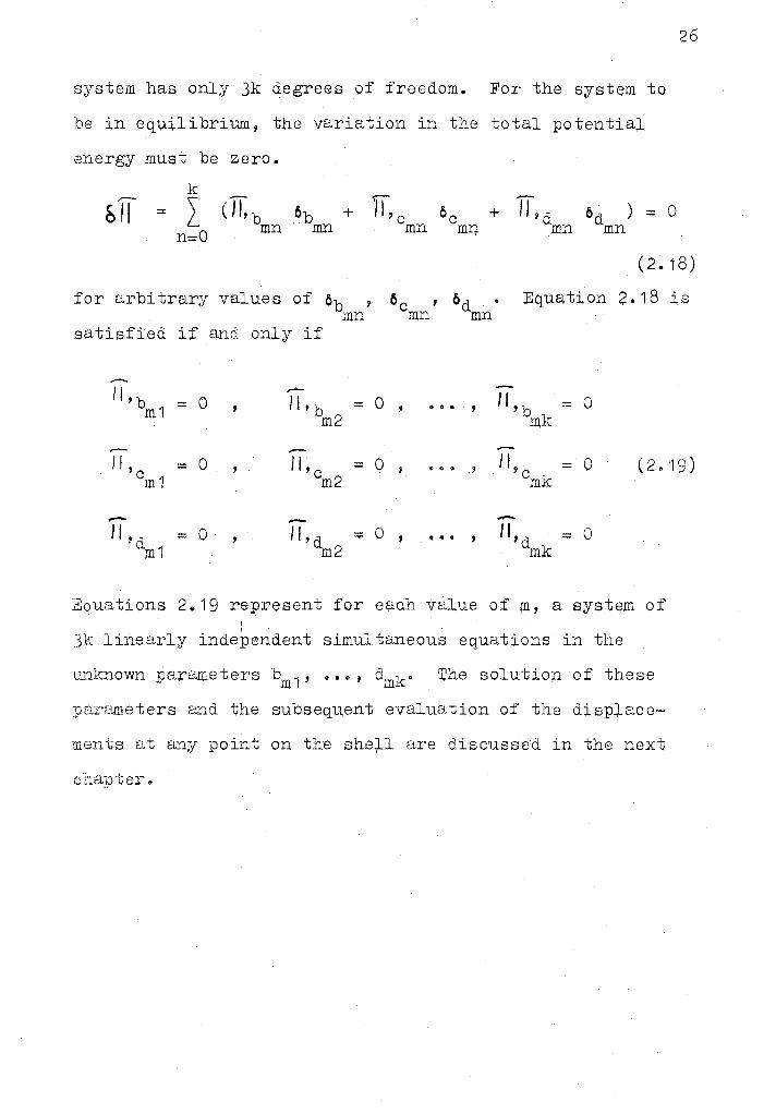
be in equilibrium, the variation in the total potential
energy must be zero.
+ TLd mn
od ) :;: 0 mn
26
(2.18)
for arbitrary values of ob , 6c , od mn mn· mn
Equation 2. 18 is
satisfied if and only if
11,b = 0 11, b = 0 '
0 ••
' 11, b = 0 m1 m2 mk
I f , = 0 11, c = 0 '
... '
I I , - 0 (2. ·19) c m1 m2 cmk
..-- -II 'd = 0 II, d = 0
' ••• ' 11, d = 0 m1 m2 mk
Equations 2 .. 19 represent for each value of rn, a system of !
.3k linearly independent simultaneous equations in the
L1r1known parameters bm 1 ' .... , dmk" The solution of these
parameters and the subseqti.,ent evalur,,tion of the disp:;l.ace-
ments at any point on the she)-1 are discussed in the next
chapter~
OH.APTER III
COM:PUTER ;30LUT ION
General - '
The numerical calculations were made on a Model .360/50
IBlVJ. comp1,1.ter. The program is suf;ficiently gene;r-~ to
ha..11.dle a cylindrical shell with arbitrary curvatures,
dimensions, boundary conditions on the straight.edges and
loadingo The varying para.meters are input ;from data cards
as needed. A listing of thEil program is given in Appendix B,
and a general flow chc;1.rt appears in Figure 4o
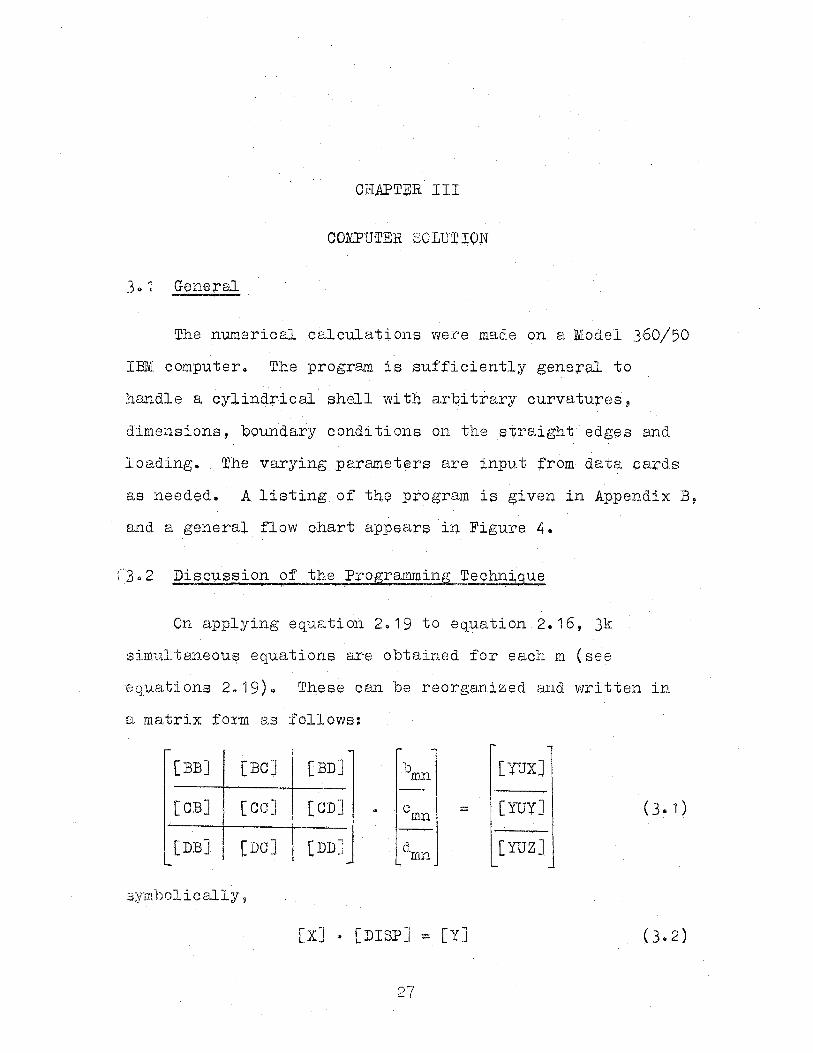
:·3· 2 ' ' . On applying eqti.ation 2.19 to equation 2.16, Jk
simu1taneou~ equations are obtained for each m (see
equations 2a ·19) ~ These can be rieorganized a.nd written in
a matrtx form as follows:
[BB]
[O:S]
[DB]
[BC] [BD]
[CC] [CD]
[DC] I [DD~;
symbolically 'j
b mn
0 mn :::::
t\nn
[X] · [DISP] - [Y]
[YUX]
(YUY] ( 3 .. 1)
[YUZ]
(3.2)
28
where the submatrices [BB], [CC], [DD], [BC], [:SD], ai.10. [CD]
are each square Md of dimension k~ The elements of each
submatrix are obtained by pqrtially differentiating 1f with
respect to the a~sociated first alphabet. S~bmatrices [YCJX],
[YUY] and [YUZ] associated with the loads are obtained by
partially differentiating 1f with respect to b, c, and q.,
respectively. The [DISP] column matrix which contains Jk
unknowns, bm 1 ' .... , dmk; is obtained by using the STQN 1
subroutine for solving a set of simultaneous linear
·equatianso
A c],ose 13xamination o:f [X] reveals that it is
symmetrical and can bE; w!'i tten as:
' - -'-
l)mJ [BC] [BD] .....
.....
'-
[X] == [BC] tsoJ [CD] ~,
...... ~
" [BD] [CD] fDPJ ... ...... ..... · . ....
....... '-
(J.J)
......
SYMMETRIC£
Consequently it is :necessary to evaluate only i;he upper
half of' the [X] matrix anct then using l:)ymmetry obtain the
remaining portion.
From the [DISP] matrix, which gives the coefficients
bmn' cmn' and dmn of the terms of the assurµed power $e;ries
,1,,....~......,,, ............ ____ , ---
·i S1rQN subroutine u,ses the method of elimination and back substitution for inverting the matrix.
(equation 2013), the displacements u, v, and w can be
easily obtained at any point on the shell.
29
The progTam given in Appendix B has been written to
give the displacements directly at every tenth point at a
section half way between the curved edges fo~ v and w
displacements and at the curved edges fo~ the u displacement.
If necessary, thi~ can easily be modified to obtain Q.is
placements at any other points on the shell. The flqw
chart shown in Figure 4 provides a ~eneral idea of the
program~ing steps involved.
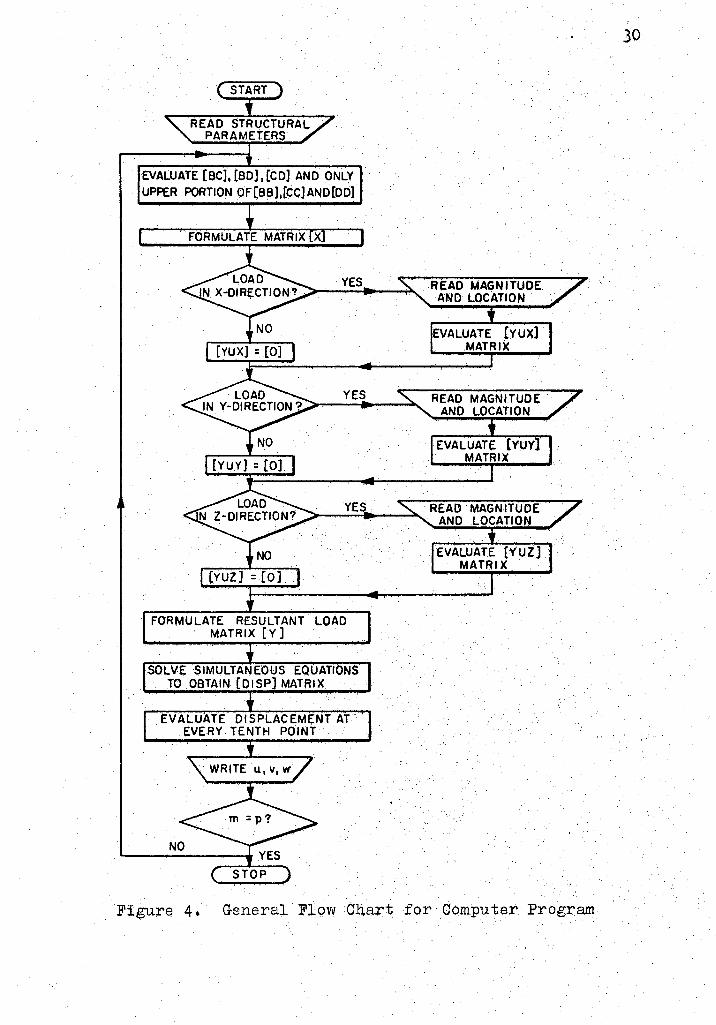
START
READ STRUCTURAL PARAMETERS
EVALUATE [BC], [BO], [CD] AND ONLY
UPPER PORTION OF[BB],(CC]AND(DD]
YES
EVALUATE [YUX] MATRIX
YES READ MAGNITUDE . ANO LOCATION
YES READ MAGNITUDE .
FORMULATE RESULTANT LOAD . MATRIX [Y]
SOLVE SIMULTANEOUS EQUATIONS TO OBTAIN [DISP) MATRIX
EVALUATE DISPLACEMENT AT. EVERY TENTH POINT
STOP
AND LOCATION
EVALUATE [YUZ) MATRIX
Figure 4. General Flow Ch.a:rt for Computer. Pr9gram
30
CH.APTER IV
NUMERICAL RESULTS
4.1 Convergence of the Solution
Theoretically, the accuracy of the solution increases
as more terms of ~he assumed displacement functions are
considered • .An exact solution can be obtained i{ the number
of these terms (values of k and p) are infinite but from a
practical consideratio:n. only a.lim;i.ted number ·can·be
considered. The question then arises: what degree of
accuracy is desired and what values of k [UJ.d p should be
used? The answer is a complex one, depending on t:):ie computer
time and storage location available, tne geometrical charac
teristics of the problem, loading cond;i.t:i.ons, and for what
p"l,\rpose the results are to be used.
A few trials were made with different values of k and
p for a flat plate simply supported on all edges and uni-.
formly loaded. ',rhe results are shown in Table II. It is
seen that increa::3ing only p or only k doei::i not substant:i,.ally
increase the accuracy but it is necessary to select a
suitable combination o;f values in both cUrections, which
depend on the accuracy desired. For circular shells this
finding is substantiated by Figu,fe 5 which shows the
31
32
TABLE II
ACCURACY OF SOLUTION FOR DIFFERENT VALUES OF k AND p
Type of structure: Flat plate simply supported on all edges
Loadi Uniformly distributed load= p0
Properties~ 1 /L = 0025 1 h/L~ = 00005~ v = Ou3 . s x _ .... 4 Exact solution (2)~ wlVIAX= (w p0 L6
)/D, where w=0.01282
p
·1
1
·1
1
1
·1
1
3
3 3 .3 5
5
7 7 "7 ' 9
k
1
2
3 4 6
7
9
14 4
7
9 14
4
7 9
'14
4
9
14
4
-w
0.011992006 00014683465 00014683465 0.014679187 00014679191 0.014679191 0.014679191 0.014679191 0.012425754 00012425728 00012425703 0.012425703 CJ. 0 ;12923400
0.012923428 0.012923456 0 .. 01292.3456 O. o ·127 84404 00012784339 0 .. 012784339 o.0·12831831
Percent Error
6.4586 + 1405356 + 14.5022 + 14.5022 + 14.5022 + 14.5022 + 14.5022 + 14.5022
300752 3.0754 300756 3.0756
+ 0.8066 + 0.8068 + 0.8069 + 008069
0.2777 0.2782
0.,2782 + 0.0922
-b
.. ,
-2
-4
-5
TYPICAi,. CROSS SECTION I - JL p - 4
LL. • 4 , ·'-: • 200 s . VI 0.3
•-0- BOYO's SOLUTION
..... k:24, pi:~ -o-k=t9, p:1
·..q., II : 24, p : I
-0-11:19,p:3
...... k:24, p =3
3.3
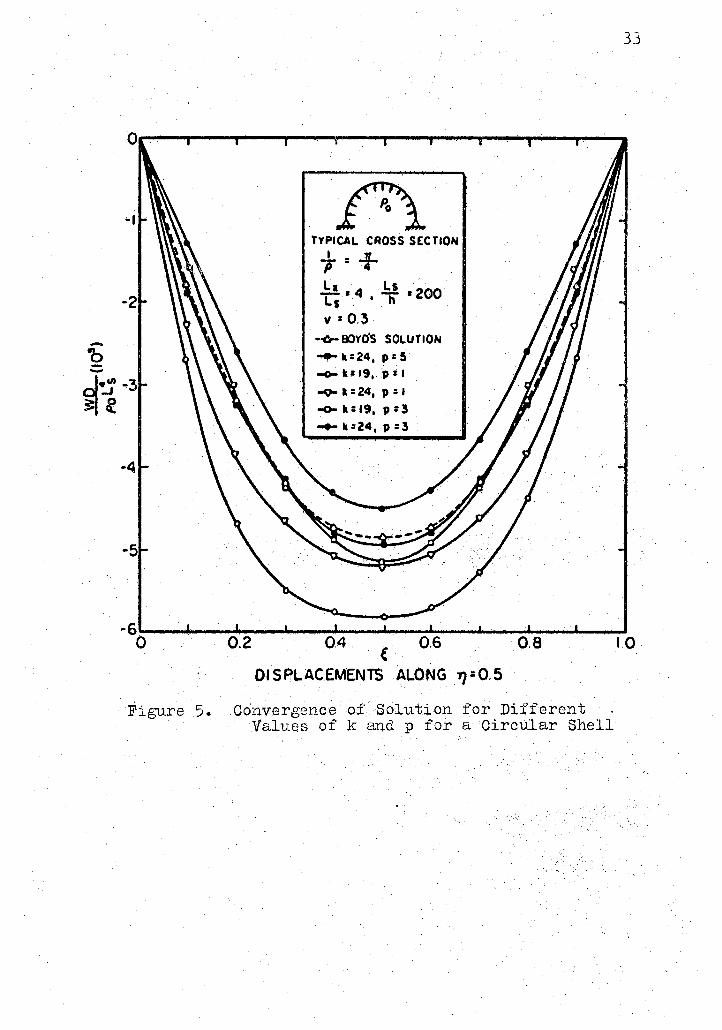
-6"'-__ _,_ __ _,,, ____ ..._ __ _.. ____ ~ __ ._ __ ...., ____ '--__ -'----' 0 0.2 0.4. .( 0.6 o.a
Figure 5.
DISPLACEMENTS ALONG 71=0.5
Convergence of Solution for Different Values of k and p for a Circular Shell
LO
34
radial displacements for various combinations of k and p
and also the solution oota:i,ned by Boyd. As. an example,
a look at the curve 9 represented by k:;;: 19, p = 3, and k= 24,
p = 3 shows that the former gives better results.
Similar investig~tio~s for noncircular shells show
that the number of terms required for convergence increase
with an increase in the numoer of terms in the curvat~re
expression. Also, more terms are required for the fixed
edge or the free edge boundary conditions ar,i.d line or point
loads.
4o2 Comparisons with Known Results for Flat Plates
The program developed was tested for several cases of
flat plates. The values of the deflections at the geometri
cal center of the plate are shown in Table III, together
with the exact solutions given by Timoshenko (2). It was
found that the.simply supported plate with a uniform load
compared most accurately with t4e exact solution. Errors
associated with the case of a concentrated load at the center L
of a simply supported plate increased as the Tl- ratio wa$ x
increased. For free boundary conditions along the straight
edge, the error was relatively large. Fo~ the cases of the
fixed straight edges, good results were obtained.
4a3 Circular Shells
Three cases for the circular cylindrical shel.l were
studiedo
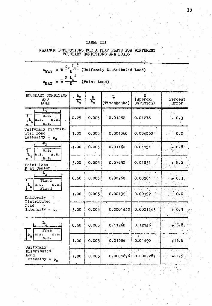
TAm..E III
MAXI~IUM DEF~ECTIONS FOR A FLAT PLATE FOR DIFFERJ;:NT BOUNDARY CONDITIONS AllQ ,LOAl)S .
- Po Ls = w D
p L 2 - s =w-r
BOUNDARY CONDITION Ls AND t; LOAD
Ly E .... 0.25 ss.s. s.s. s •. s •.
Uniformly Distrib-uted Load 1.00 Intensity= Po
.lJX ,. .1 1.00
J; s.s. s.s. s.a. s s.s.
Point Load 3.00 p at Center
,... Lx ·I 0.50
~ Fixed
s.s. s.s. Fixed
1.00 Uniformly ,;,
D:i,stributed LO Eid
(Uniformly Distr:i,buteµ l,oaq)
(Point Loa.d)
h w w .
r (Approx. s (Timoshenko) Solution)
0.005 0.01282 0.01278
0.005 0.004060 0.004060
..
0.005 0.011q0 0.01151
0.005 0.01690 0.01831
0.005 0.00260 Q.00261
I \ 0.005 0.00192. 0.00192
Int!;lnsity = Po 3.00. 0.005 0~0001442 0.0001443 ' .,
I I .. · 1. Lx ., I o. 50
f 0.005 Q.11360 I O.l21J6 ·
E Free s.s. s.s.
s.s. 1.00 0.005 0.01286. 0.01490
.
Uniformly .. Distributed Loud 3.00 o.oo, 0.0001876 0.0002287 Intensity = Po
35
'.
Percent Errov
- 0.3
o.o
!. . '
.., o.8
f + a.a
·.
i l + O.J
:·j.'
·o.o
'.
·:.. (). t
..
+.6.8
,.;15.a
+21.9
Figure 6 shows the radial deflections for a simply
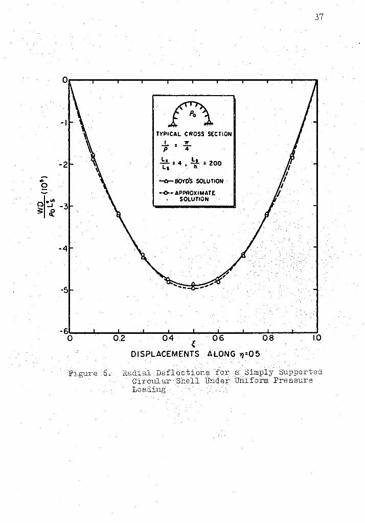
supported circular shell under uniform pressure. For the
same number of terms in the displacement f1m.ctions the
maxi.mum error when compared with Boyd's values was less
thsn one percent.
J6
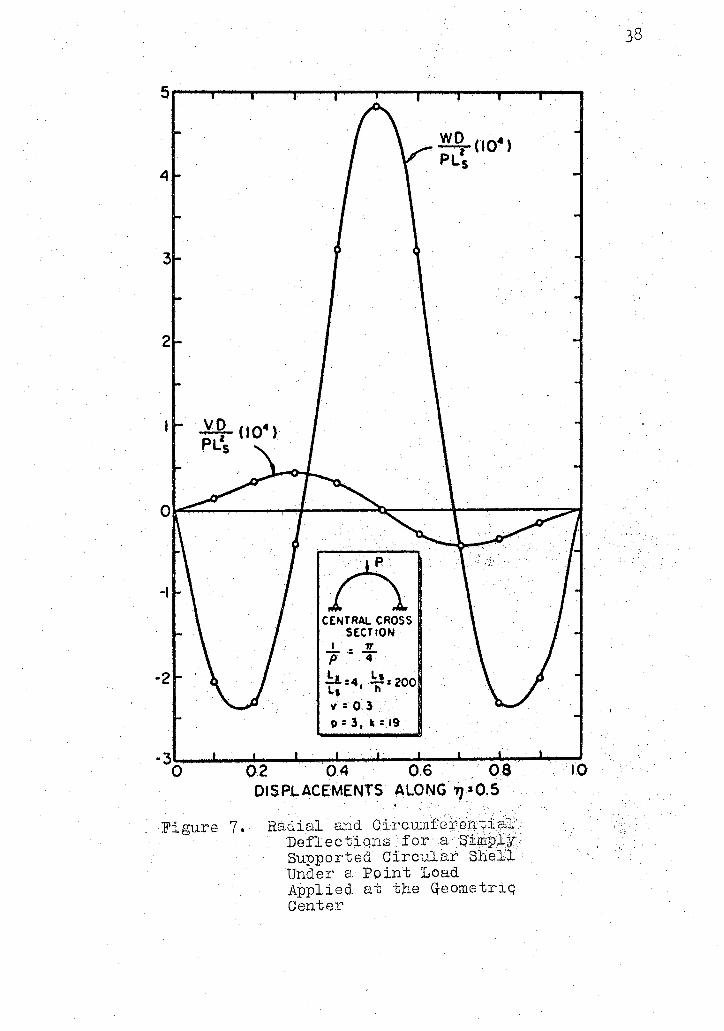
Figure 7 shows the radial c.md circumferential displace
ments for the same shell discussed above but under a
point load applied at the ~eometrtc center of the shell.
In order to compare this method of analysis with
mcperimental results under a variable loading intensity 1 the
shell shown in Figure 8 was a:nalyzed~ 1.I'his shell has been
a.nalyzed and tested experimentally by Lundgren.
The shell was 2 cm. thick, had a 1 ength of 3 m. and an
arc length of 5 mo with a rct¢l.ius of curvature of 9 m. For
praotica.l, purposes it was assumed to be simply supported on
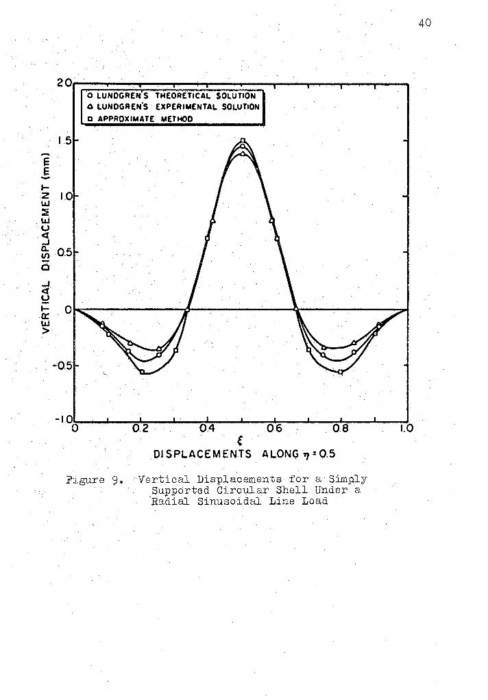
aJ.l edgeso The vertical displacement curves for the three
case~i are shown in J?igure 9o At the center of the shell the
:X:"Gsu.1.ts agree with Lundgren 1 s experimentttl as well as
th.Ernreti.eal valueso However, at the springings, the results
obta:ined did not agree closely with either Lunclgren 1 s
exporimenta1 or theoretical valueso As pointed out b;y
L1mdgren this is due to the fact that the edge conch tions
1.:1t the S}H'ingings were rather obscure in the experimen.ta1
~rnt,,u:pT and an approximate theor;y wa.s used by him in his
-t;}:ieox~f~ ea,l vvorl~o It is po ssi bl tJ tl1at: the met11od p1~e ser.tted.
provides better ;results at the springings than
Lu.ndg::cen' s experimental or theoretical results.
-_, 0 - ' -
-I
-2
-------
TYPICAL CROSS SECTION I ,r - : -p 4
"I; : 4 , ¥ : 200
-0- eo1o's SOLUTION
·~- APPROXIMATE SOLUTION
37
0 .II) :.J -3
~ cf
-4
-5
-6~--~--~ ...... _.... ____ .... __ _,_ __ --"~--"'----...L.---""'-----' o o.~ 04 c os 0.8 1,0
DISPLACEMENTS ALONG 71=05
Figure 6. Radial Deflections for a Simply Supported Circular Shell Under Uniform Pressure I,ioading
5,--,,---,----..---,---,,--._.---------------
4
3
2
-I
·2
CE~TRAL CROSS SECTION
I • Tr p·-a-.!;J. :4, Li: 200 L1. , l'I
v : o. 3 p: 3, k : 19
w~ no•, PL5 . ·
-3~--.._ __ ....._ __ ..._ __ .,_ __ ..._ __ ....., __________ _,_ __ _, 0 0.2 04 06 0.8 1.0
DISPLACEMENTS ALONG. "1 =0,5 · . '
Radial and Circumferentia-1 . Deflectiql'ls for a Simply
Supported Circular 3hel'l Under a Point Load Applied. at t;he Geometriq Center
38
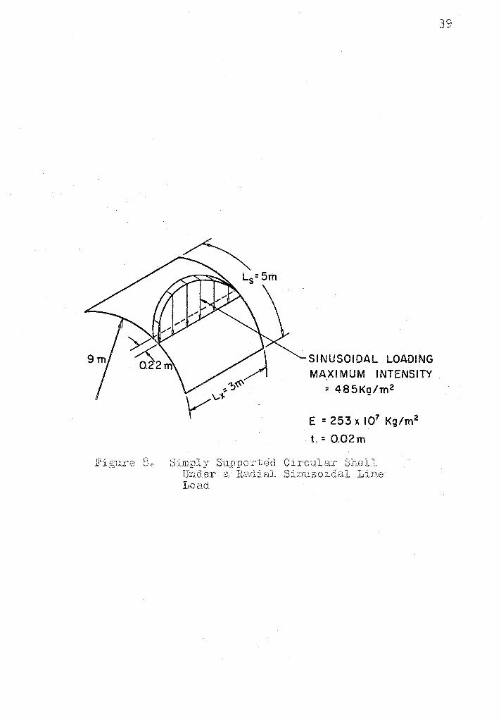
SINUSOIDAL LOADING MAXIMUM INTENSITY
~ 485Kg/m 2
E = 253 x 107 Kg/m2
t. = 0.02m
39
E E -t-z w :E w u <l ...J Cl. V) ..... c ..J. <t u I-er u.J. >
20,------------_... _______________________________ _
1.5
0.5
0
O LUNOGRE,. S THEORETICAL SOLUTION O '-UNOGR[N'S EXPERIMENTAL SOLUTION
O APPROXIMATE METHOD
-1.0....._......, __ __."-____ __. ________ ...__--'" __ ...___-' o 0.2 o.4 oG a.a 1.0
F:Lgure 9o
e DISPLACEMENTS ALONG 11 = 0.5
Vertical Displacements for a Simply .supported Circular Shell Under a Radial Sinusoidq). Line Load
40
41
4o 4 Non.circular Shells
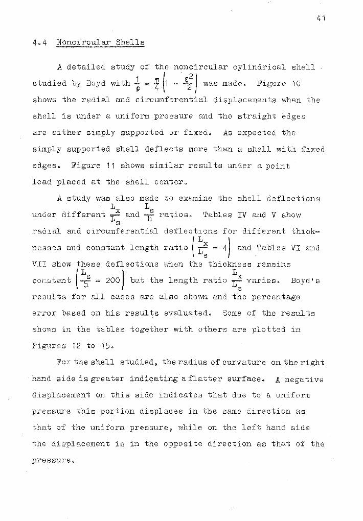
A detailed study of the noncircular cylindrical shell
studied by Boyd with ! - i (1 - ~:) was made. Figure 10
shows the radial Emd circmnferential displacements when the
shell is under a uniform pressure and the straight edges
are either simply supported or fixedo As expected the
simply supported shell deflects more than l;l shell with fixed
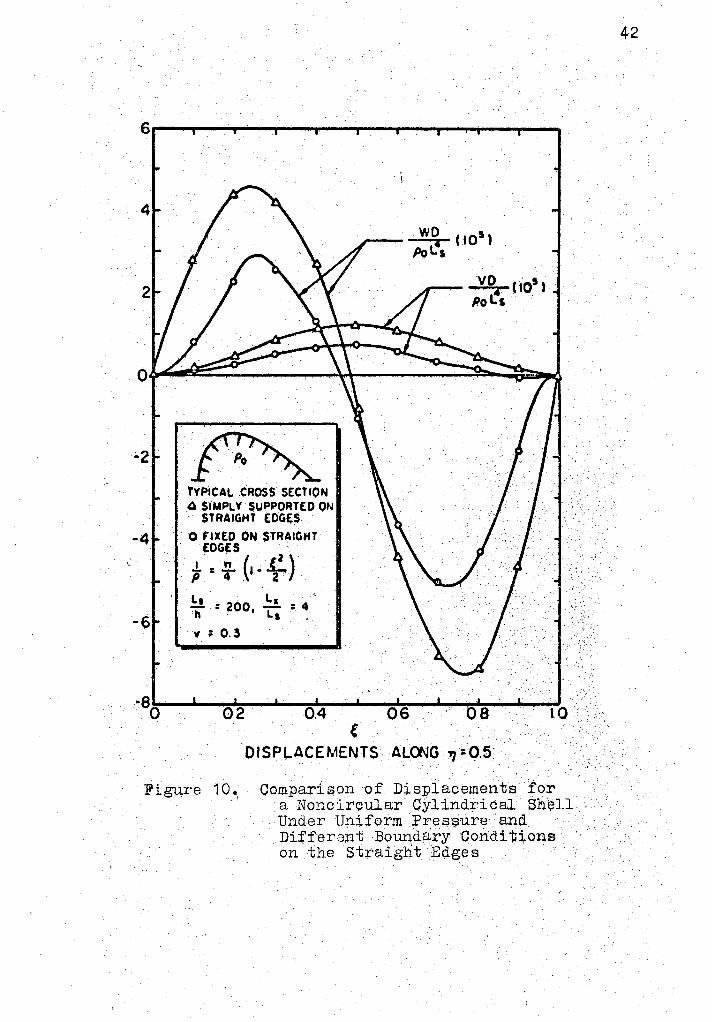
edges o Fi6:rure 11 shows similar remu ts under a point
load placed at the shell center.
A study was also made to examine the shell deflections
under L L
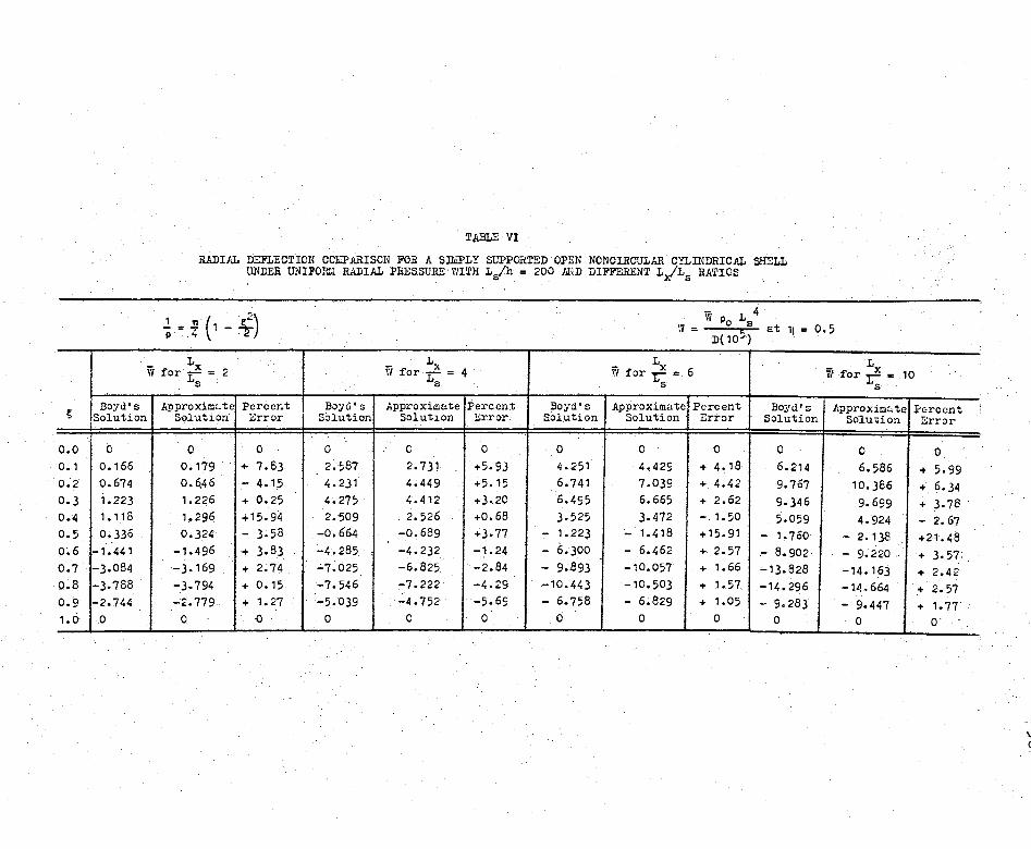
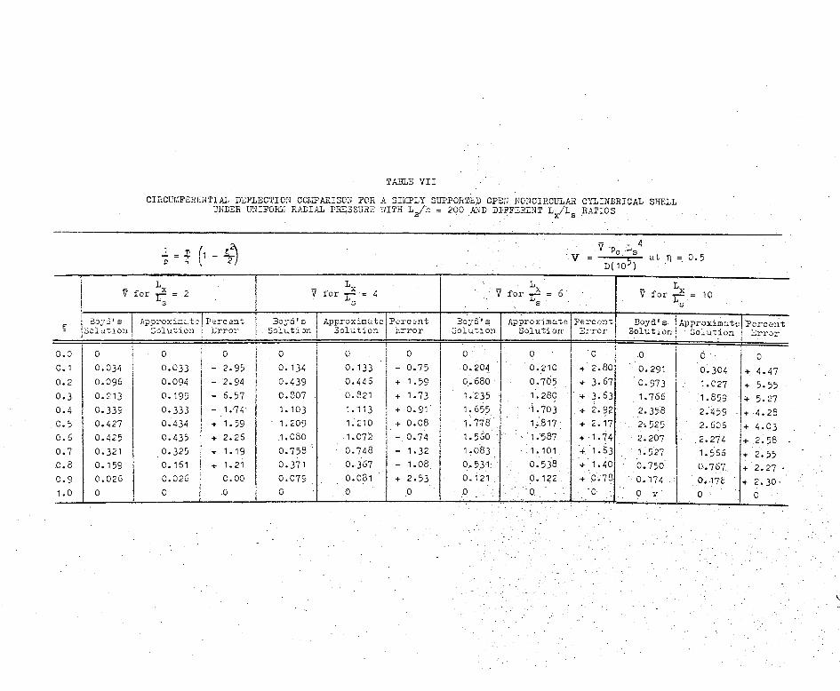
different Lx and -f' ratios. Tables IV and V show ~1 s
radial and circumferential
nesses and co11stant length
de fl e c ti ons
. x (
1 ratio Ls==
for different thick-
4) and Tables VI a;nd
VII show deflections when t;he thickness remains
C01'lf3tFm-t 200) but the length ratio ~x varieso Boyd 1 s s
:cesul ts for all cases are also shown and the percentage
error based on his results evaluate do Some of tb.e reS1.il ts
shown in the tables together with others are plotted in
Fig1J.res 12 to 15Q
I!'or the shell studied, the radius of curvature on the right
hand side is greater indicating a flatter surface. A negative
displacement on this side indicates that due to a uniform
J)l:°8f3sure this portion displaces in the same dj.rection as
that of the uniform pressure~ while on the left hand side
the displacement is in the opposite direction as that of the
pressureo
6,----,,----,--....,.--.......,..---------------.....---------
4
2
WO CI05 l Pol's
VO. ( 10' l Po l!'s .· .·
•2 ~
-4
-6
TYPICAL CROSS SECTION .4 SIMPLY SUPPORTED ON
STRAIGHT EDGES
O FIXED ON STRAIGHT . EDGES .
,~ ~· (,~f) ~ : 200, ~ =. 4 ti L1
" : o. 3
~so~· __ ...._ __ ~ __ .... __ "'"-_..j----"---"'--..... ---'---' 0 2 . 0.4 06 0 8 . · lO
Figure 1 O • . ,·
DISPLACEMENTS A~Q\JG '1 ~0.5 ·
Comparison of D:i..splacememts for a Non.circular· Cylindrical Sh~ll . Under Uniform .J?res~ure and Di:t'ferent Boundary Conditions on the Straight E\iges
42
30;.-----...... ---.... ...... ----------------....---,r-,--,
25
20
15
10
5
-5
-10
-15
~.·· ..
1 ·. :~· TYPICAL c~ss SECTION
O SIMP\..l' Sl/~ED ON STRAIGHT EDGES
O FIXED ON STRAIGHT EDGES
.L: ~ (,-~) p . 4 Z .· Ls . La - : 200,-....: 4 h · L1 'II = 0. 3
-20--~---------...._--...... ---~-...... --o . 02. 04 06 08 ;10 . e OISPLACEMEN1:S ALONG 11 ::Q.5
Co,mpar;i.son. Of D:i,sJ)lEtCol116n-(;p :f<:)i; .. · Noncircv.lar Cylindric°']: \J.h(0).J>.
Under a Hadiull:v- Di:t·ccted ··· · Point Load at the Shell Center and Different; Bo1,1.ndar;y Condi tj:ons on the Straight
· Edges
43
Ill 0
8
6
-2
-6
-8
~ TYPICAL CROSS SECTION
i: .1!:.(1- f:.) P 4 '2
-10
Ls T =100
v: 0.3 -12
k =29, 11= 5
4 eovds SOLUTION · •14 0 APPROXIMATE
SOLUTION
4:6 . l,.s . Lx 4 Ls:
-16~--...___....,,__... ____ .,.._--', __ -.I, ______ -.., __ -'-__ -'
0 0.2 0.4 0.6 ().8 DISPLACEMENTS ALONG 71:0.5
Figure 12. Ra~ial Deflec"tions for a Si~ply Supported Open Noncircular Cylindri9al Shell.Under Uniform Radial Pressure with L /h.=100 and Difterent L~L
8 Eatios ·
1.0
44
-II) 0 - II)
15-----------..-----------------------------
10
0
Lx = 10 Ls
Lx _ G L.s -
__ Lx =4 Ls
Lx = 2 Ls ·
0 ..J
3: 0 .Q..
-5
-10
-15
··: ,;,
TYPICAL CROSS SECTION
t= : (1- \2) ~s = 200
v = 0.3
k=29, p:5 ~ aovds SOLUTION O APPROXIMATE
SOLUTION
-20-.--------------..----~--..---I O 0.2 0.4 0.6 0.8 1.0 ..
Figure 13.
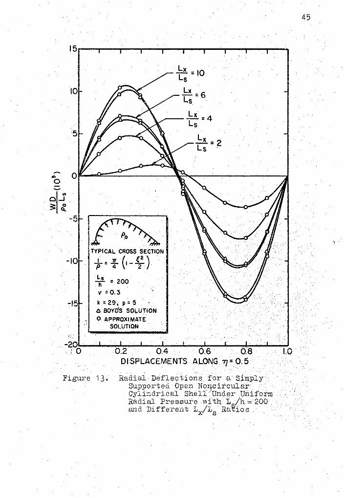
DISPLACEMENTS ALONG 71 = O. 5 . .
Radial.Deflectioris for a SJmply Supported Open Nonc:ircular · Cylindr;ical Shell 'Undr=r Uniform · Radial Pressure wftn 1
8/h == 200
and Different Lx/18
Ra~;ios.
45
6
4
2
-2
-4
-6
~ TYf>ICAL CROSS SECTION + = : (1 - (22 )
Ls Lx 11=200, T;' = 4
v: 0.3
k = 29, p: 5 .o BOYD'S SOLUTION O APPROXIMATE
SOLUTION
W D (10') PoL~
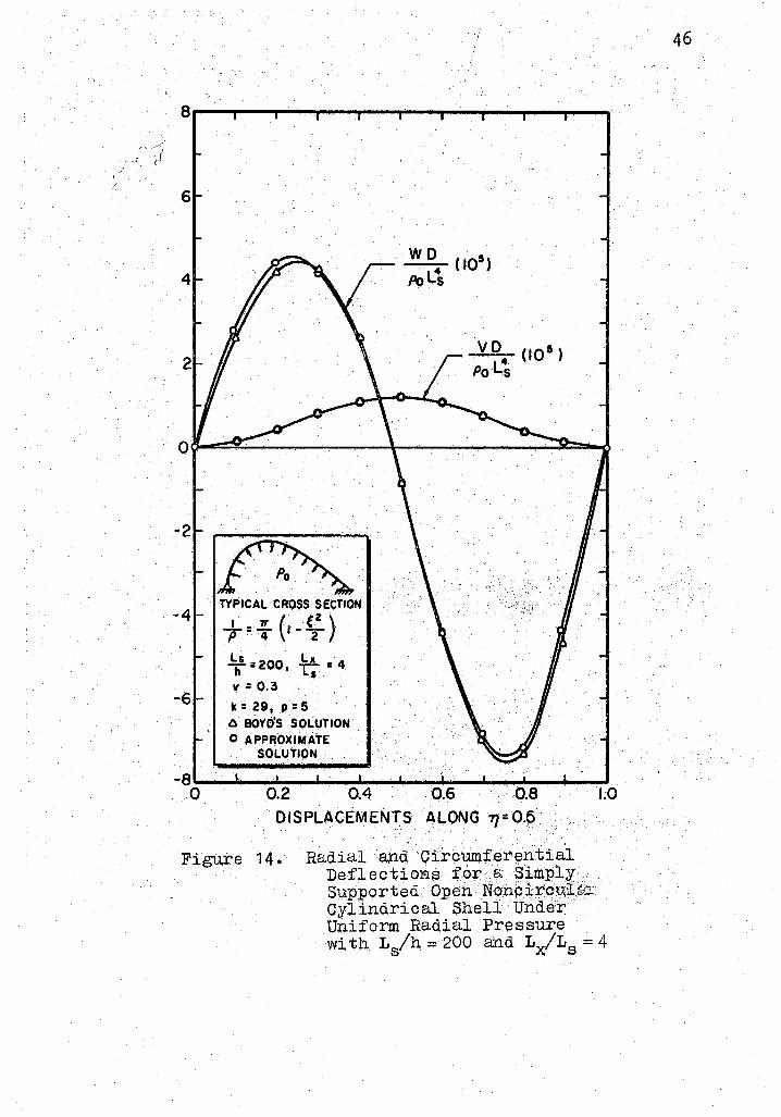
VD (10') Po Lt
-8!'---...... ~~--~~---,,.._....4 __ ....;,,..~...a..--...l,....-..J 0 0.2 0.4 0.6 . 0.8 1.0
DISPLACEMEN,:s 4LONG 77=0.~.
Figure 14. Radial @d Ci.rp'Umfer~ntial Defleci:;iOR!=, for R ~imply. Supported. Qpeh NohpirctA;Ie:~ Cylindrical Shell· Under····· Uniform Radial Pressure with L
8/h = 200 and LxfL8 = 4
46
2.0,-----......,.---........ --------------
1.5
1.0
0.5
.... mo o~iiiiiiiiiiis;:;~F--:T"""----~----r1r\---_,...-------j
01~ ·;: 0
Q.,
-0.5
-1.0
-0.5
-2.0
TYPICAL CROSS SECTION
..!..=· . .,,. (1 .. f.:) p 4 2
~s = 800
v: 0.3
k = 29, p = 5 O BOYD'S SOLUTION
O APPROXIMATE · SOLUTION
-2.5.__ ...... _ ....... _..,..._ ....... _....., ....... -.._ ............ i;.__... _ _, 0 0.2 0.4 06 LO .
Figure 15.
DI $PLACEMENTS ALONG 77=0.5
Radiru. Deflections for a Simply Supported Open · . ~"· Noncircula~ Cylindrical Shell Under Uniform Radial Pressure with 1
8/h = 800
and Different Lx/'Ls aatios
47
I;
o.o o. 1 0.2 0.) 0.4 0.5 0.6 0.7 0.8 0.9 1 • '()
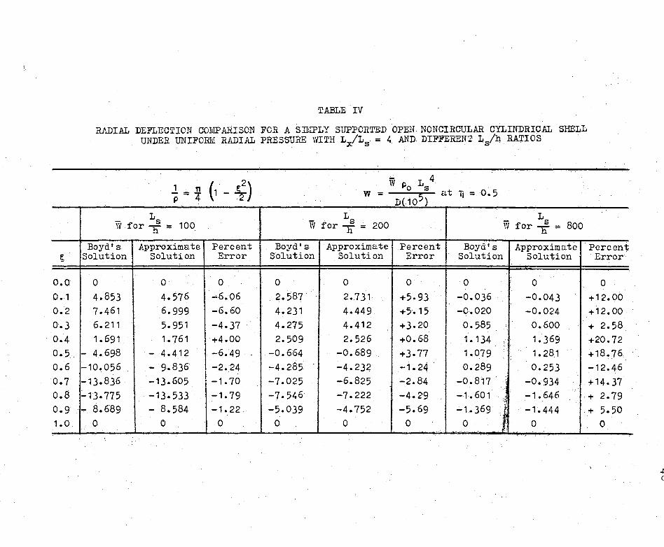
TABLE IV
RADIAL DEFLECTION comPARISON FOR A SII\'IPLY SUPPORTED OPEN NONCIRCULAR CYLINDRICAL SHELL UNDER UNIFORM RADIAL PRESSURE WITH LxfLs = 4 AND DIFFERENT Ls/h RATIOS
w = W L 4
Po s 5 at Ti = O. 5 p D(10 )
- Ls L L 100 w f s 200 - s 800 W for h = , or h = W for h =
Boyd's Approximate Percent Boyd's Approximate Percent Boyd's Approximate Solution Solution Error Solution Solution Error Solution Solution
0 0 0 0 0 0 0 0 4.853 4.576 -6.06 2.587 2.731 +5. 93 -0.036 -0.043 7.461 6.999 -6.60 4.231 4.449 +5.15 -0.020 -0.024 6.211 5.951 -4.37 4.275 4.412 +3.20 I 0.585 0.600 1.691 1. 761 +4.00 2.509 2.526 +0.68 1.134 1. 369
- 4.698 - 4.412 -6.49 -0.664 -0.689 +3.77 1.079 1.281 -10.056 - 9.836 -2.24 -4.285 -4.232 -1. 24 0.289 0.253 -13.836 -13.605 I -1. 70 -7.025 -6.825 -2.84 -0. 817 -0.934 -13. 775 -13.533 -1. 79 -7.546 -7.222 -4.29 -1. 601 l
-1. 646 l A.
- 8.689 - 8.584 -1. 22 -5.039 -4.752 .... 5.69 -1-369 l -1. 444 0 0 0 0 0 0 0 0
Perccn1; Error
0 +12.00 + 12. 00 + 2.58 +20.72 +18.76 -12.46 +14-37 + 2.79 + 5.50
0
-+ c
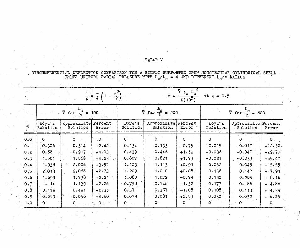
TABLE V
CIRCffi11FERENTIAL DEFLECTICN COMPARISON FOR A SI!lll'LY SUPPORTED OPEN NONCIRCULAR CYLINDRICAL SHELL UNDER UNIFORM RADIAL PRESSURE WITH L/Ls = 4 AND DIFFERENT Ls/h RATIOS
atlj=0.5
v Ls v Ls 200 v Ls Boo for h = _100 · for n = for h = -
~ Boyd's Approximate Percent Boyd's Approximate Percent Boyd's Approxim&te Percent
Solution Solution Error Solution Solution Error Solution Solution Error
o.o 0 0 0 0 0 0 0 0 0 0.1 0.306 0.314 +2.42 o. 134 o. 133 -0.75 ;..0.015 -0.017 +12.50 0.2 0.881 o. 917 +4.03 0.439 0.446 +1. 59 -0.036 -0.047 +29.70 0.3 1.504 1. 568 +4.23 0.807 0.821 +1. 73 ~0.021 -0.033 +59-47 0.4 1. 938 2.006 +J.51 1. 103 1. 113 +0.91 0.052 0.045 -15.55 0.5 2.013 2.068 +2.73 1. 209 1. 210 +0.08 0.136 0 .. 147 + 7 .. 91 o.6 1. 699 1.738 . +2. 24 1.080 1.072 -0.74 o. 190· 0.205 + 8.16 0.7 I 1.114 1.139 +2.26 0.758 0.748 -1. 32 0.177 0.186 + 4.86 o.a 0.479 0.491 +2-35 0.371 o. 367 -1.08 0.108 -0. 113 + 4.39 0.9 0.053 0.056 +4.60 0.079 0.081 +2.53 0.030 0.032 + 6.25 1. 0
I 0 0 0 0 0 0 0 0 0
+ \j
s
o.o 0.1 0.2 0.3 0.4 0.5 0~6 0.7 o.B 0.9 1. 0
TABLE VI
RADIAL DEFLECTION CC:L:PARISCN FOR A SllilPLY SUPPORTED OPEN NCNCIRCULAR CYLINDRICAL SHELL UNDER UNIFOPJ.l RADIAL PRES.SURE \'/ITH L
6/h = 200 AND DIFFERENT L:xl'Ls RATIOS
W Po Ls 4 'V- atlj=0.5 · - D{ 105>
- Lx - Lx 4
- Lx 6 - Lx w for r = 2 W for L = w for r = w for r = 10
s. s. s $
Boyd's Approxim.:.:te Percent Boyd's Approximate Percent Boyd's Approximate Percent Boyd'~ .Approximtcte :Percent Solution S-0lution Error Solution Solution Error Solution Solution Error Solution Solution Error
b 0 0 0 0 0 0 0 0 0 0 ()
0.166 o.n9 + 7.83 2.-587 2. 731 +5-93 4. 251 4.429 + 4.18 6.214 6.586 + 5.99 o.674 o.&46 - 4.15 4. 231 4.449 +5.15 6.741 7.039 +. 4.42 9.767 10.386 + 6-34 1.223 1.226 + 0.25 4.275 4.412 +3.20 6.495 6.665 + 2.62 9-346 9.699 + 3.78 1.118 1.296 + 15. 94 2.509 2.526 +0.68 3.525 3.472 - . 1. 50 5.059 4-924 - 2. 67 0.336 0.324 - 3.58 -0.664 -0.689 +3°77 - , • 223 - 1.418 +15.91 - 1. 760 - 2.138 +21.48
-1. 441 -1.496 + 3.83 -4.285 -4.232 -1.24 - 6.300 - 6.462 + 2.57 .- 8.902 - 9.220 + 3. 57; -3.084 -3· 169 + 2.74 ~1.025 -6.825 -2.84 - 9.69) -10.057 + 1. 66 -13.828 -14.16) + 2.42 -3.788 -3-794 + 0.15 -7-546 ~7-222 -4.29 -10.443 -10.503 + 1. 57 -14. 296 -14.664 + 2. 57 -2.744 ~:::. 779 + 1.27 -5.-039 -4.752 -5.69 - 6.758 - 6.829 + 1.05 - 9.283 - 9.447 + 1. 77
0 0 -0 0 0 0 0 0 0 0 0 o·
\ (
v
.aoyQ I $ s Solutiou
o.o I 0 0.1 0.034
!
0.2 0.096 i 0.3 0.213
I 0.4 I 0.339 0.5 ! 0.427 0.6 0.425 0.7 0.)21 o.8 0.159 0.9 0.026 1.0 0
TABLE VII
crn.cm~FEREiHIAL DEFLECTION COi,IPARISOii FOR A 311'.iPLY SUPPORTED CPElf NONCIRCULAR CYLINDRICAL SHELL UIIDER UJIIFOfil, RADIAL PR::;SSU,t:E WITH L
8/h = 200 _AND DIFF:SRLNT L;/L
8 RATIOS
1 = ~ (1 _ f22\ p ~ \ ,J
Lx for r = 2
:,
Approxim::.:te Percent :iolution ::.;rror
0 0 0.033 - 2.95 0.094 - 2.94 o. 199 - 6.57 0.333 - 1.·74 0.434 + 1. 59 0.435 + 2.26 0.325 + 1. 19 o. 161 + 1. 21 0.026 c.oo 0 0
I j
1 ;
I i
I I i I
' i i
!
' I I
Lx v :for r = 4 s
Boyd's ! Appraxim:c.:tc P.:,rcc'nt Solu ti Jn j Solution 1:;rTor
I
I
I 0 0 i 0 o. 134 0.133 ! - o. 75 ! I 0.439 0.44 6 + 1. 59 I
o.S2i
l o.307 + 1. 73 1. 103 1. 113 + 0.91 1.209 1.210 I· 0.08 I
+ I
.1.080 1.07::: - 0.74 I
I
I 0.758: 0.748 - 1.32 I I 0.371 0.367 - 1.08 I
0.079 0.081 + 2.53 I 0 .0 0 ..
v - at T] 0.5
Lx L. v for r = 6 v for Lx = 10 s s
3o:.rd' ~ Approxim~tc Perccmt Boyd's IApproximutc Solution Solution Error Solution i ::iolution
!
I 0 0 I
I 6 0 I 0
0. 204 ) o. 210 + 2.80! o. 291 0.304 I I
3. 671 0.680 · 0.705 + 0.973 I 1.027 3.63 1 "Jc; . 1. 280 + 1. 766 1.859
1: ;5; l L 703 ·+ 2.~2 2.358 2.'159 1. 718 I ,;"817 2.17 2.525 2.606 + 1. 560 .. 1~587 + · 1-74 2 .• 207 .2.274 1.083 .· 1.101 + 1. 63 1:527 1.566
:
o. 5,31 0.538 + 1.40 0.750 0.767 0.121 0.122 + 0.78 ·. o. 174 o.17E .0 0 0 0 v 0
. ..
·Perce.mt l:;rror
0 4.47 I: 5.55 5.27
+ 4.28 + 4.03 + 2;58 + 2.55 + 2.27 . + 2. 30 ·
0
52
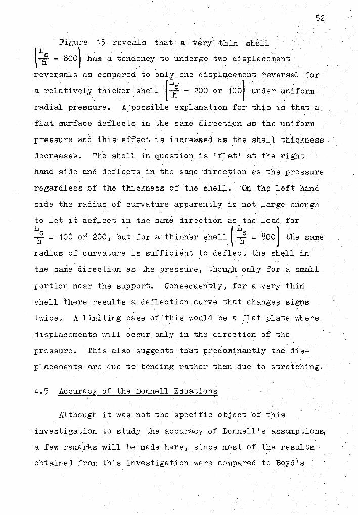
Figure 1-5 reveals that a very thin shell
r Lhs l \ = 800 has a tendency to undergo two displacement
reversals as compared to only one displacement reversal for
a relativel;)'\ thicker shell (Li:' = 200 or 100) under ~iform
radial pressure. A possible explanation for this is that a
flat surface deflects in the same direction as the uniform
pressure and this effect is increased as the shell thickness
decreases. The shell in question is 'flat• at the right
hand side and deflects in the same direction as the pressure
regardless of the thickness of the shell. On the left hand
side the radius of curvature apparently is not large enough
to let it deflect in the same direction as the load for
Li:' = 100 or' 200 , but for a thinner shell I i' =. 800 J the same
radius of curvature is sufficient to deflect the shell in
the same direction as the pressure, though only for a small
portion near the support. Consequently, for a very thin
shell there results a deflection curve that changes signs
twice. A limiting case of this would be a flat plate where
displacements will occur only in the direction of the
pressure. This also suggests that predominantly the dis
placements are due to bending rather than due to stretching.
4.5 Accuracy of the Donnell Equations
Although it was not the specific object of this
investigation to study the accuracy of Donnell's assumptions,
a few remarks will be made hE;Jre, since most of the results
obtained from this investigation were compared to Boyd's
. 53
results who used Donnell's assumptions regarding the contri
bution of the shearing force Qs to the equilibrium of forces
and the contribution of i:;he circumferential displacement v
to the expressions for the change of curvature and twist.
For the cases studied here, there was no significant
difference between Boyd's solution and the approximate
method. Since both methods are approximate (although they
use different approximations) very little can be said about
the relative accuracy of either. For short thin shells
under uniform load either method is expected to give
reliable results. However, for very long and relatively
thicker shells under some loads producing a large shear
force, this approximate method would prove more; versatile.
5. 1 Surnmarx
CHAPTER V
SUlVIlVIARY ,AND CONCLUSIONS
A method has been :presented to determine the deforma ...
tions of a general noncircular cylindrical shell using an
energy method and an approximate technique where displace
ments are assumed as finite power series. Special cases of
the flat plate, circular shell, and the noncircular shell
used by Boyd were investigated and the following obser
vations made:
1. Through comparison of deflections obtained by
other methods for identical shells, this method of analysis
was shown to give valid results.
2o The method is valid for open noncircular cylin
drical shells having curvatures expressible as power series.
The curved ends of the shell must be simply supported, but
any arbitrary boundary conditions can be imposed on the
straight edges.
3o In this method uniform. 1 line, Ol~ point ·
loads anywhere on the shell in any direction can be
considered.
4. For the same degree of accuracy, convergence of
the solution is most easily obtained for a flat plate. More
54

55
values of k and pare required as the number of term:s in the
curvature expression increase.
5. Convergence for the simply supported boundary
condition along the straight edges is most easily obt~ined,
and is most difficult for the free ed~es. The free edge
condition along~= 0 cannot be obtained for aJ.l the cases
since the power series here has to be approximated by a
single term only.
6. Less values of p and k are required for convergence ~ .
for a uniformly distributed load than for either a line.or
point load,
?. By treating the general solution associated with
a point or a line loa.d- in any .. direction. as ·an influence,.
function it is possible to obtain a solution for any
arbitrary loading condition, This fact can be used to
obtain solutions to problems that have e:j_ther a vertical,
hydrostatic, parabolic, or any other shaped loading function.
Bo A 'flatter' portion of the shell deflects in the
same direction as the applied pressure and this effect is
increased as the shell becomes thinner. The portion.of the
shell having a relatively smaller radius of curvature tends
to deflect in the opposite direction so that the overal].
displacement of the shell is predominantly due to bending
rather than stretching.
9. Although different approximations were used in
this method and the method of Boyd, the. res.ul ts were cl·ose
enough to be acceptable for Engineering purposes.
56
10. This method does not give very accurate results
for short shells because an extremely la:rge number of terms
are required for convergence of solution in this case.
5.2 Conclusions
The method presented provides engineers with an approxi~
mate technique for calculating displacements for open non
circular cylindrical shells having curvatures expressible
as power series. The curved ends of the shell must be
simply supported but any arbitrary boundary conditions can
be imposed on the straight edges. Classical, exact methods
of analytical solution can.not be applied to take into
account satisfactorily different types of loading functions
which must be expanded into a series. The method used here,
satisfactorily overcomes this limitation and proviq.es an
approach where any arbitrary load placed anywhere on the
shell surface can be considered. It is necessary to select
a suitable combination of the number of terms in both
directions of the assumed displacement functions for proper
convergence of the solution. A large number of terms in
one direction only with an insufficient number in tne other
will not give satisfactory results. The number of these
terms required for convergence increases as the shell
geometry becomes more complicated. Also, more terms a:re
required for the fixed edge than for the simply supported
e:dge exi.d it j_s easier to obtain. convergence for uniformly
distributed loads than either for point or line loads.
A shell where the radius of curvature is constant (example
a flat lJlate or a circular shell) and under a uniform
pressure will deflect in the direction of the load but for
a variable radius of curvature, the 'flatter' portion of
57
the shell deflBcts in the direction of the applied :pressure
and the remaining portion deflects in the opposite.direction,
so that the overall effect of bending is predor.o:in~t .rath~r
th2m that of stretching. This effect becomef, more ,pre..:
dominant as the shell bee ome s thinner. . The re suits bbt'aine d<
by this method give answers ,that. are clo:se to Bqyd'.!:s :for:
most cases' but.it is expected that for :relatively .. thi"c;nc ...•
and long shells under shear loads this method. would ip~q;·e · .·· . ' .. ··.•• =.· · .. · ·'
more versatile.
5.3 Suggestions for Further Work
During this study, many interesting topics were noted
which should be studied.
It may be possible to introduce arbitrary boundary
conditions even on the curved edges through the choice o1
pol;irnomial functions for displacements in both the longi~
tudinal and circumferential directions.
The possibility of taking irito account discontinuous
boundary conditions on any edge needs some attention.
Additional properties of the shell should be in-
corporated into this theory. For example, when applying
this method to the analysis of shell structures for
aircrafts, including helicopters; submarines, and space
vehicles, it would be desirable to incorporate anisotropic
material properties as well as variable thickness.
58
An investigation should be made into the possibility of
extending this method for structures where the curvature is
not constant at each section of the shell, but varies w:j_t):l
length. An e;x:ample of this would be an open, noncircular
tapering cylindrical panel.
Other approximate methods may be considered. In
general, such methods can be classified into three basic
groups as follows:
1. Methods which satisfy the governing differential
equations but not the boundary conditions. Examples of
this method are the Point Jnatching method and the Trefftz-
Morley method.
2G Methods which satisfy the boundary conditions
but not the differential equations. The method discussed
in this research belongs to this group. Also the interior
collocation, Kantorovich, EJnd the Galerkin ,methods are
included in thi.s group. For a brief and precise discussion
of the methods of the first two groups the reader is
referred to reference 15.
3. Methods that satisfy neither the differential
equations nor the boundary conditions. The well-known
finite difference method ("16) and the finite· element method
for usual. types of elements (17 and 18) belong to this group.
Most of the methods discussed above reauire the use of a ~ . .
d.igi tal computer~ mainly because of the necessity of
inverting a large matrix. An approxima,te solutioJ+ where
it would not be necessary to invert a matrix and probably
eliminate the use of the digital computer would be most
welcome. Such a method might use the results obtained
from this investigation as a guide.
This method could also be extended to multiple bay
shells where each bay has the same or different radius of
curvature.
59
BIBLIOGRAPHY
Flugge, w. Stresses in Shells. Verlag, Inc. , 196°'57
( 1 ) New York: Springer-
(2) Timoshenko, s., ands. Woinonsky-Krieger. Theory .2.f Plates and Shells, 2nd ed. New York: McGrawHill Book Company, 1959.
(3)
(4)
(5)
( 6)
(7)
(8)
Kraus, H. Thin Elastic Shells. and sons;-rnc., 1967.
New York: John Wiley
Lundgren, H. Cylindrical .§_hells. Vol. 1(Cylindrical Roofs). The Danish Technical Press. The Institution of Danish Civil Engineers, Copenhagen, 1960.
Kempner, Joseph. "Energy Expressions and Differential Equations for Stress and Displacement Analyses of Arbitrary Cylindrical Shells." Jour. of Ship ~· (June, 1958), pp. 8-19. - -
Romano, Frank, and Joseph Kempner. "Stresses in Short Noncircular Cylindr;i.cal Shells Under Lateral Pressure." Jour. of Appl. Mech., Trans. ~' Vol. 84 ( 1962), pp. 669-674.
l\'Iarguerre, K. "Stabili tat der Zylinderschale veranderlicher Krummung. 11 ~ TM 1302 (July, 1951).
Boyd, D. Ea II Analysis of Open Noncircular Cylindrical Shell.s. 11 AIAA, Vol. 7, No. 3 (1969).
(9) Sokolnikoff, r. s., and R. M. Redheffer. Mathematics of ,?h;y_sics SE£ Modern Engineering. New York: McGraw-Hill Book Company, 1958.
(10)
( 1 1 )
Donnell, L. H. "Stability of Thin-Walled Tubes Under Torsion." ~ Rep. No. 479 (1934).
Oden, J. T. Mechanics of Elastic Structures. New York: McGraw-Hill Book Company, 1967.
60
( 12)
( 13)
(14)
( 1 5)
( 16)
(17)
(18)
Kantorovich, L. V., and V. I. Krylov. Approximate Methods.£! Higher Analysis. (English Translatio~), P. Noordhoff Ltd., Groningen, The Netherlands, 1958.
Langhaar, Henry :L. Energy Methods in Applied Mechanics. New York: John Wiley and Sons, Inc., 1962.
Kurt, Carl Edward. "Free Vibrations of Open Noncircular Cylindrical Shell Segments." (unpub. Ph.D. the sis, Oklahoma State University, 1969).
Leissa, A. w., w. E. Claussen, L. E. Hulbert, and
61
A. T. Hopper. "A Comparison of Approximate Methods for the Solution of Plate Bending Problems.'' AIAA/ASME 9th Structures, Structural Dynamics and Materials Conference, Palm Springs, California""1April 1-3, 1968).
Ramey, Jimmie D. 11 A Numerical Analysis of NoncirculcJ.r Cylindrical Shells." (unpub. Ph.D. thesis, Oklahoma State University, 1969).
Zienkiewicz, o. c., and Y. K. Cheung. Element Method in Structural and Mechanics. London: McGraw--Hill Comp~ny Limited, 1967.
The Finite Coii"tinuum Publishing
Przemieniecki, J. s. Theory of Matrix Structural Analysis. New York: McGraw-Hill Book Company, 1967.

APPENDIX A
DERIVATION OF THE STRAIN ENERGY
EXPRESSION OF A NONCIRCU~AR
CYLINDRICAL SHELL
-1. 1:rhe shell is cylindrical, i.e., its cross section
is characterized by the plane curve resulting from the inter
section of the median surface and a plane normal to the
axis of the cylinder.
2. The right-handed coordinate system shown in
Figure 1 gives the coordinates of any point (x,s,z) in the
shell.
3ti The material of the shell is isotropic, homo
geneous and elastic.
4. The thickness of the shell is very small compared
to the other dimensions of the shell.
5o The deformations u, v~ and ware small compared
to the thickness of the shell and do not significantly
change the geometry of the shell.
60 The Kirchoff·-Love assumptions of thin-walled
shell theory are applied; Le. 1 normals to the median
surface of the undeformed shell remain straight, unextended,
and normal to the median surface after deformation.
62
63
7. The loading is appli~d at the median surface.
8. The stresses at any point in the shell wall are
related to the strains through Hooke's Law for plane stress.
Ao2 Relation Between Stress Resultants
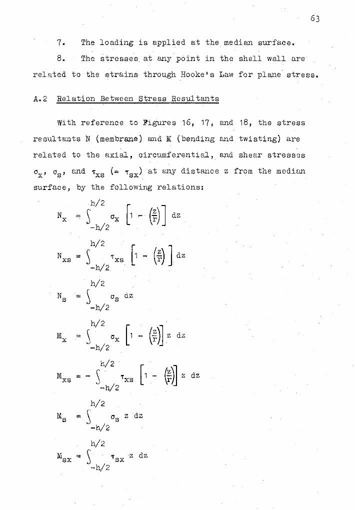
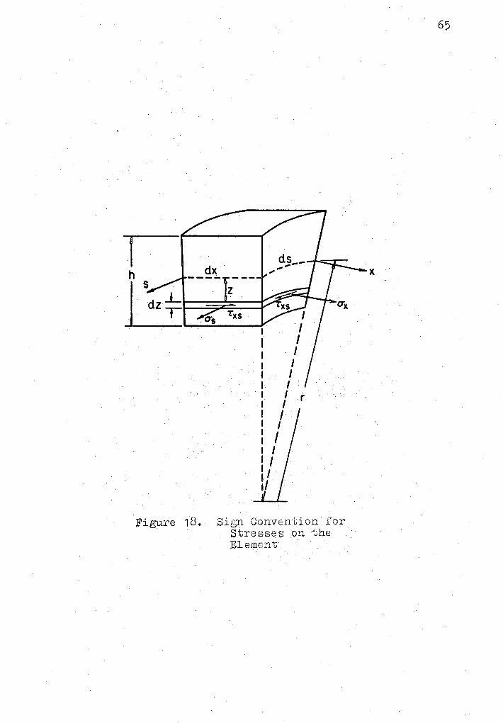
With reference to Figures 16, 17, and 18, the stress
resultants N (membrane) and M (bending and twisting) are
related to the axial, circumferential, and shear stresses
ox, os, and ,-xs (= 'T sx) at any distance z from the median
surface, by the following relations:
h/2
Nx = S Ox [1 - (~) J dz -h/2
h/2
Nxs = ~ 'xs [1 - (;) J dz -h/2
M x
l\lIXS
Ms
IVISX
h/2
= ~ Os dz
-h/2
h/2
[1 - (i)] z = s OX dz
-h/2
h/2
[1 - (F)] = - s 'Txs z dz
-h/2
h/2
= ~ Os z dz
-h/2
h/2
= ~ 'T SX z dz
-h/2
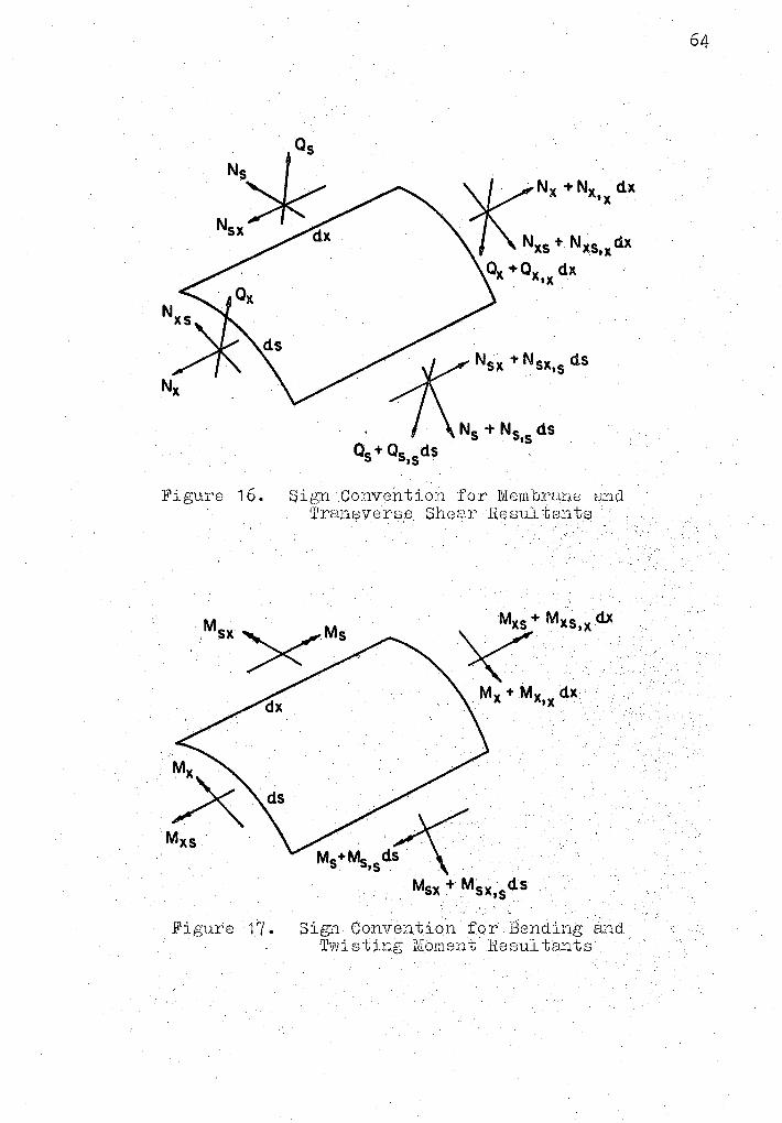
Figure 16. ~i{:,"l~l ,Convention for lVlcmbrane and r11ransversp Shear Resul tantf;'l
\. >+ MxJ,x dx " ..... . Mx + Mx,x dx
I!1 igure l7. · Sign Convention for Bending. and 1rwisting Nioment Rosul t.smts
64
dx
Txs I ...,__,...; _____ ., . I
I I I I I
I r I I I I I I
1/
Figure 18. Sign Convention for Stresses on the Element
65
x
66
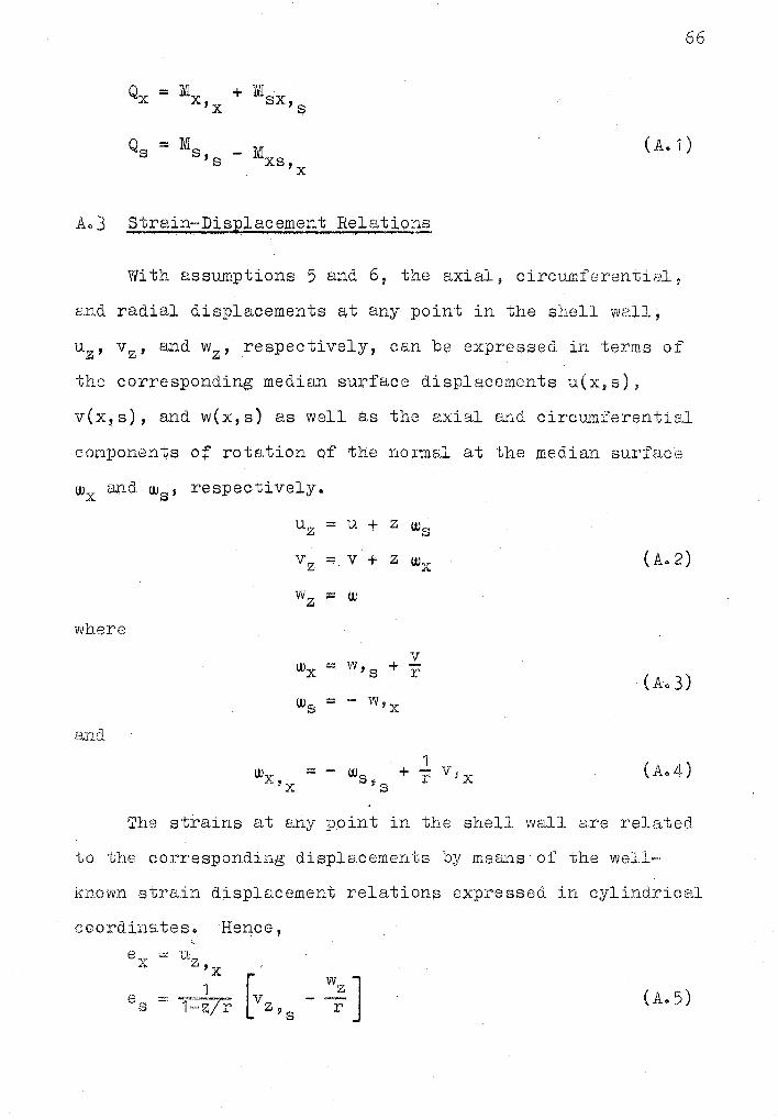
Qx = Mx + IVlsx 'x '$
Qs = Ms - Mxs ( Ao 1)
's 'x
Ao3 Strain-Displacement Relations - , I
With assumptions 5 and 6, the axial, circumferential,
and radial displacements Ett any point in the shell wall,
uz, vz, and wz, respectively, can be expressed in terms of
the corresponding median surface displacements u(x,s),
v(x, s), and w(x, s) as well as the axial and circumferential
components of rotation of the normal at the median surface
WX and UJS' respectively.
Uz = u + z Ws
vz ...., v + z w.,,. .,,_ (A. 2)
w z ;:;::: w
where
v Wx = w,s + r
(Ao3) Ws = - w,x
and
1 Wx = - w + v~x
'x s ~ C< r .., (A.4)
The strains at any point in the shell wall are related
to the corresponding displacements by means of the well·~~
known strain displacement relations expressed in cylindrical
coordinateso Hence,
ex -· ,·1 1.....-rw,Z
,cJ 'x c:::. 1 [v :: J (Ao5) = kTr -,, s z 9 s

67
= vz + 1-z/r uz 'x 's
1 ( A. 5)
in whic~ ex, es, and exs are the axial, circumferential,
and shearing strain$, respectively, describing the state
of strain in any plane tangential to the cylindrical
surface [r(s), z]. In terms of the displacement and
rotation components of the median surface, the strain 1 displacement relations become:
e = s
It is also a c9nvenience to have these strains
expressed in terms o:(' the corresponding median surface
strainso From equations A.J, A~4, and A.6
ex = exo + z w s,x
0 8 so z - .'.:;o J '"'s - + 1-z/r [wx 's
z [ws (1 - ;) e = exso + T-z/r Wx XS 's 'x
+ (2~) (exso - 2wz) J
z [~ - ~) w - 2-~ J ::::: e - 1-z/r xso r X:,x r
in which
8 xo ::::: u,x
e = v,,~ - (¥) so.
~1xso == u, s + v,x
""""'-""' ... -----1Physica.1 interpretation of w
8 , W , and W~r
. . . 'x x,s A'x is available in many references (see Reference 1),
(A. 6)
( A. 7)
(A. 8)
Equation Ao7 can also be presented in the form
ex = exo ..... z xx
es = eso -(1-~/r) >ts
8 xs = t1-~/r) exso - (1 + 1-~/r) xxs
in which,
= - (JI :::; W ' XX
= Wx::,: ~e~o) = [w,s + (f)].
8- {~) [v, 5 - (i)]
= Wx = - Ws,6
+ 2~ (e 4 so + ~u.iz) 'x
Ao4 Stress Resultants in Terms of Displacem~nts
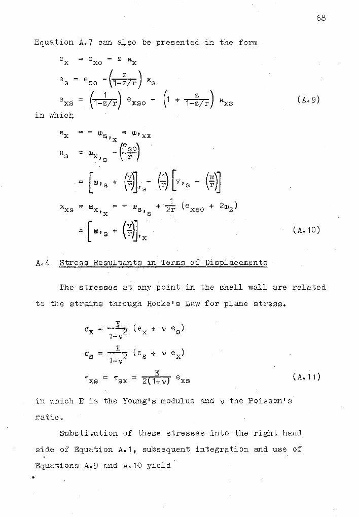
68
( Ao 9)
( A. 10)
The stres~es at any point in the shell wall are related
to the strains through Hooke I s Law for pla.Yle stresso
( A. 11)
in which E is the Young's modulus and v the Poisson's
Su.bsti tution of these stresses into the right hand
sidl::J of Equation Ao 1, subsequent integration and use of
Equations A.9 and Ao10 yield ..
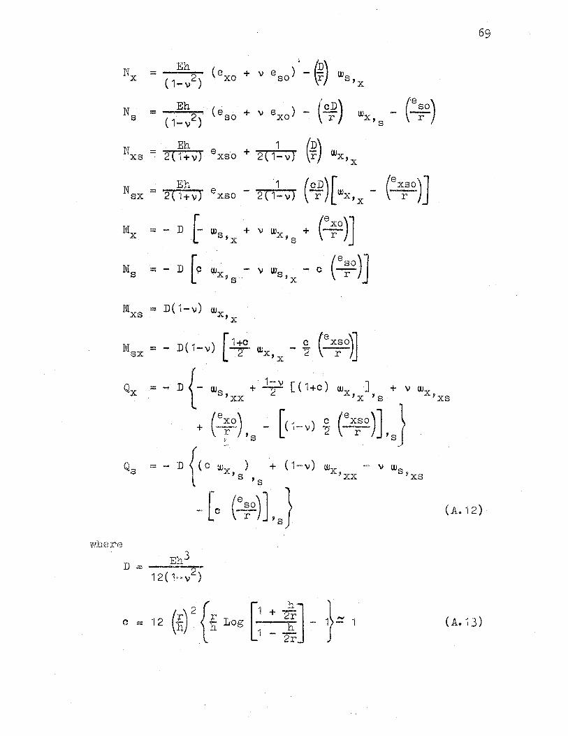
69
= Eh2 \exo + v eso) -~) Ws (1-v) \r 'x
Eh \r.£._rD) ... (~rso) = ·. 2 (eso + v 8 xo) - wx (1-v) · 's
Eh 1 (Dr) = 2 ( 1 + v) e XS o + 2 ( 1- v) Wx , x
Nsx = Eh 1 (Q_.rD)[wx,x _ (0
xrso).J 2 ( 1 + v) ~ xso - 2 ( 1- v)
-· - D f- W + v Wx + (: r)J stx 's
= - D [9 w - v w -. c (0
;0
)]-x, s · s,x
N1 - D(1-v) w XS X,X
= - D( 1-v) [ 1f °'x, x - % ex:o)J
= ... D {- w8 + •1 ~ v [ ( 1 +c )
'xx
- [<1-v) ~ + (~xa.) r ' > s
Q s = - D {(c 'JJ.. ) . + (·1-v) xjs
's
-[c (~)J.J ( Ao 12) ·
where
( A. 13)
70
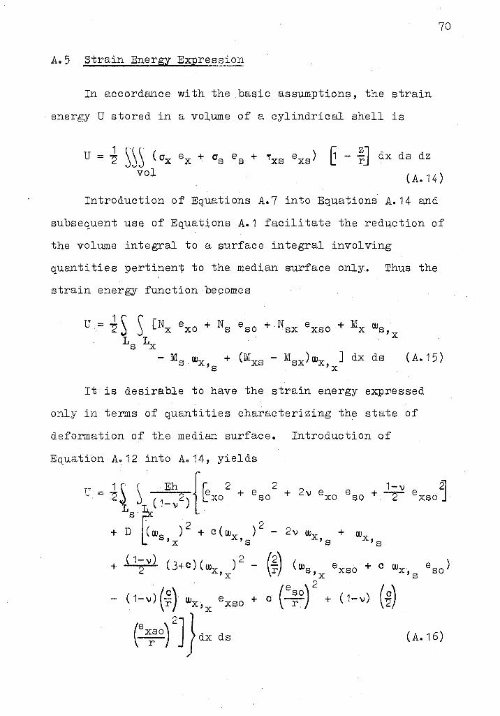
Ao5 Strain Energy Expres~ion
In accordance with the basic assumptions, the strain
energy U stored in a volume of a cylindrical shell is
6 - ~:] dx d s dz U = J ~~~ ( 0 x ex + 0 s 9 s + 'T'xs exs) vol ( A. 14)
Introduction of Equations A.7 into Equations A.14 and
subsequent use of Equations A.1 facilitate the reduction of
the volume integral to a surface integral involving
quantities pertinen"\; to the median surface only. Thus the
strain energy function becomes
1 s '~
(Nx exo + NS + Nsx + Mx U=~ eso exso Ws Ls Lx
'x
- M w + (Mxs - Msx)wx J dx ds (A.15) s x,s 'x
It is desirable to have the strain energy expressed
only in terms of quantities characterizing the state of
deformation of the medi~ surface. Introduction of
Equation Aa12 into Ao 14, yields
+ w x, s
( A. 1 6)
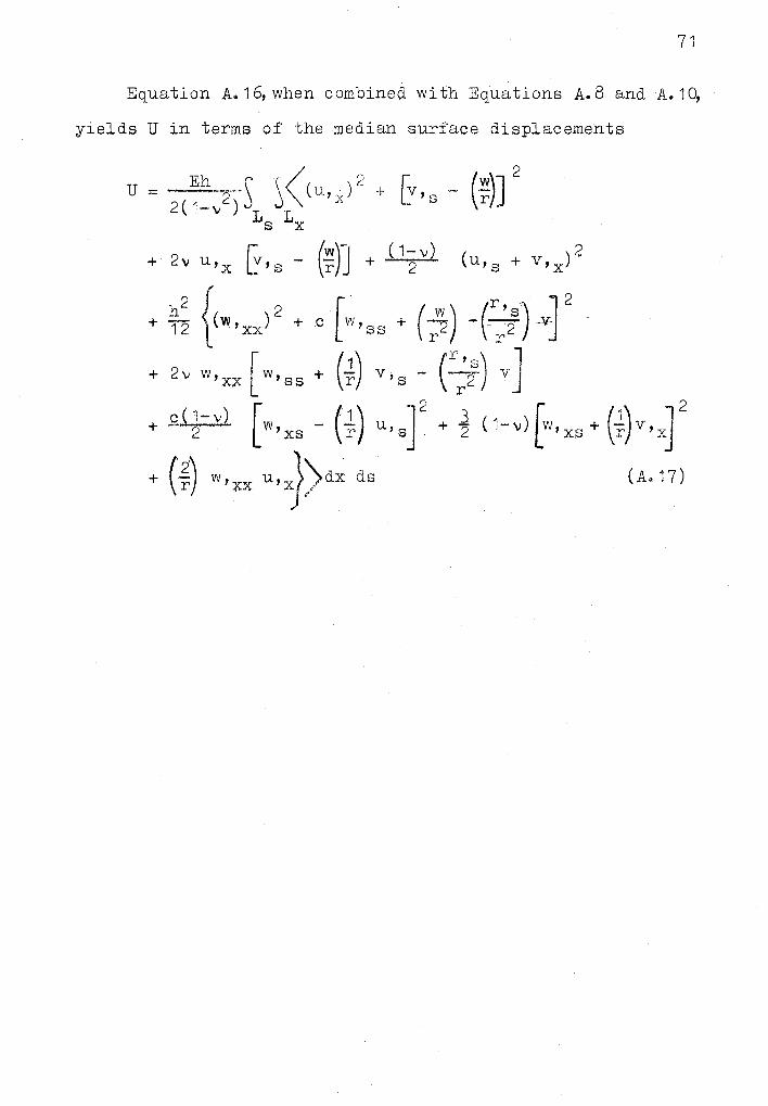
71
Equation A.1~when combined with Equations A.8 and A.1~
yields U in terms of the median surface displacements
U = 2
( ~~, 2 )\ ~ ~ ( u, x )2 + [v , s - ( f )J 2
s x
[ f'l!.r)~J· + J 1-2
v) ( ) 2 + 2~ u,x L~'s - ( u,s + v,x
+ c [w'ss + (;'2) -()) v]2 c~) v,s - ()) v J
+ g_LJ-v) [ (1) ]2 2 w 'xs r u, s
+ rn w'xx u,x})dx ds
+ l 2 ( 1-,i(w,xs + (i)v,xr ( A. 17)
APPENDIX B
COMPU~ER PROGRAM
72

CARO , 0001 C 0002 C 0003 C 0004 C 0005 C 0006 C 0007 C 0008 C 0009 C 0010 C 0011 C 0012 C 0013 C 0014 C 0015 C 0016 C 0017 C 0018 C 0019 C 0020 C 0021 C 0022 C 0023 C 0024 C 0025 C 0026 C 0027 C 0028 C 0029 C 0030 C 0031 C 0032 C 0033 C 0034 C 0035 C 0036 C 0037 C 0038 C 0039 C 0040 C 0041 C 0042 C 0043 C 0044 C 0045 C 0046 C 0047' c 0048 C 0049 C 0050 C 0051 C 0052 C 0053 C 0054 C 0055 C
REFERENCE:
AN APPROXIMATE ANALYSIS OF OPEN NONCIRCULAR CYLINDRICAL SHELLS
PURPOSE:
TO. EVALUATE , USING THE ENERGY METHOD , TH.E DISPLACEMENTS IN AN OPEN NONCIRCULAR CYLINDRICAL SHELL SIMPLY SUPPDIUED AT THE CURVED ENDS AND WITH ANY BOUNDARY CONDIT IONS ON THE STRAIGHT EDGES , SUBJECT TO ANY ARBITRARY LOADING• .
PROGRAMMER:
ASHOK NAIN GRADUATE ASSISTANT SCHO~L OF CIVIL ENGINEERING OKLAHOMA STATE UNIVERSITY STILLWATER, OKLAHOMA
GENERAL COMMENTS: THE PROGRAM HAS BEEN WRITTEN TO GIVE THE DISPLACEMENTS DIRECTLY AT EVERY TENTH POINT AT A SECTION .HALF WAY BETWEEN THE CURVED EDGES FOR V AND W DISPLACEMENTS AND ~T THE CURVED ED~ES FOR THE U DlSPLACEHENT .
DESCRIPTION OF PARAMETERS:
CAAXI = MATRIX OF COEFFICIENTS OF POLYNOMIAL FOR SHELL CURVATURE ex, = STRAIN ENERGY MATRIX C8Bt,CCCt,CDDt,IBCt,C8D1,CCDt = SUBHATRICES DF MATRIX ext CAI = CX) STORED CDLUHNWISE . iYt = COLUMN MATRIX DUE TO LOAD
73
c YUXI ,CYUYI ,YUZI .. COLUMN MATRICES DUE TO LOAD IN X,S,Z DIRECTIONS CDISPt = ~ATRIX .CONTAINING UNKN~WN COEFFICIENTS 84.11,CClt,DCI) cut' CVI ,I.Wt = DISPLACE HEN:'{ MATRICES JN x,s,z DIRECT IONS CPXt,CPYt,CPZI = MATRICES OF LOADS IN, X,S,Z DIRECTIONS CSPXlt,CSPX21 1 CSPYlt,CSPY2t,CSPZlt,CSPZ21 AND CEPXlt,CEPX21, CEPYlt,CEPY21,CEPZlt,CEPZ~t = MATRICES DE~IN1NG LOCATION AND LIMITS OF LOAD MATRICES CPXt,CPYt,CPZt NN =e HIGHEST,, POW.E~ .Q.f: ,.CP.Ef..F.,1,~ JE.tH .Of .P.0.L.YNOHIU FOR CURV~TURE . K = NO. OF ·TERMS' LESS ONf"'FO~'··poijER' 'SERIES IN CURVED Ol~ECTION HZ: NO. OF TERMS FOR SERIES ALONG STRAIGHT EDGES CPI Zl=N . ZJ=N BAR Ll~L2,L3 =NO.OF LOADING FUNCTIONS IN x,s,z OIRfCTIONS HOB= H/LS HOA = H/LX PR= POISSON'S RATIO PIE= 3.141593
CARD 0056 C 0057 C 0058. C 0059 C 0060 C 0061 C 0062 C 0063 C 0064 C 0065 C 0066 C 0067 C 0068 C 0069 C 0010 C 0071 C 0072 C 0073 C 0074 C 0075 C 0076 t 0077 C 0078 C 0079 C 0080 C 0081 0082 0083 0084 0085 0086 0087 0088 0089 C 0090 C 0091 C 0092 0093 0094 0095 0096 0097 0098 0099 100 0100 101 0101 102 0102 104 0103 106 Oi04 107. 0105 108 0106 300 0107 311 oios 0109 312 OllO 313
ALFA,BETA,GAMA,DELU,DMEGA,THETA,PHI z PARAH!ETERS DEFINING . BOUNDARY CONDITIONS ON JHE STRAIGHT ED.GES OF JHE SHELL
SUBROUTINES REQUIRED:
l. RRAY - CONVERTS IXI INTO IAI AND VICE VERSA 2. SJQN..,. SOLVES A SET OF SIHULTANElUS LINEAR EQUATIONS.
INPUT FORMAT SPECIFICATIONS:
1 ST CARD ------.... NN,K,MZ I All INTEGERSI PUNCHED RIGHT JUSTIFIED WITH FORMAT 13121
2 ND CARD------- AAXCII (REALI
74
PUNCHED RIGHT JUSJIFIED WITH FORMAT (4015.81 3 RD CARD.------- PR,BOA,HOB,HOA,PI E CALL REAL I
PUNCHED RIGHT JUSTIFIED WITH FORMAT C5Dl4~8) 4 TH CARD ----- THETA,PHl,OMEGA,DELTA CALl. REALI
PUNCHED RIGHT JUSTIFIED WITH FORMAT (4014.8) 5 TH CARD ---·-- ALFA,BETA,GAMA CALL REALI
PUNCHED RIGHT JUSTIFIED WITH FORMAT C3Dl4.81 6 TH CARD--~---- l.1,L2,l3 CALL INTEGERSI
PUNCHED RIGHT JUSTIFIED WITH FORMAT (3121 TYP. LOAD CAkD -- THE NUMBER OF THESE DEPENDS ON THE LOADS SPECIFIED BY Ll,L2,L]. All LOADS lN X DIRECTION ARE CONSIDERED FIR~l, LOADS IN S DIRECTION NEXT AND LASTLY THE LOADS IN THE Z DIRECTION. PX U 1, SPX 1 C JI, SP X2C 11, EPX 1 CI I, EP X2 C II PYCll,SPYlCll,SPYiCll,EPYlCll,EPYZCII PZCll,SPZ1Cll 1 SPZ2Cll,EPZ1Cll,EPZZCII PUNCHED RIGHT JUSTIFIED WITH FORHAl C5Dl4.8J
IMPLICIT REAL•8CA-H,O-ZI DIMENSION AAXC101,XC90 ,901
1D1SPC90l,UC1~1,V(101,WC101, OJ~ENSION PXClOJ 1 SPX1Cl01
,AC8l001 ,YC901 , YUXC30J,YUYC301,YUZl301 , SPX2( 10) ,EPXll .101 ,EPX2l 101 ,SPY2Cl01 ,EPYlC 101 1 EPY2Cl01 ,SPZZClOI ,EPZlC 101 ,EPZ2C101
• 1 PYClOI ,SPYll 101 2 PlflOI ,SPZlllOI
EQUIVALENCE CXCl,11 ,AClll FORMAT 0121 FORMAT (4015.81 FORMAT (5014.81 FORMAT (5014.81 FORMAT (4014. Sf FORMAT C 3014.81 FORMAT 13121 FORMAT (3X,5Dl5.81
'
FORMATllX, 'THE ABOVE DISPLACEMENTS ARE TO BE M~LTIPLIED BY A lFACTOR CH•H•B•A•P0/01' l
FORMAT ClX,'U DISPLACEHENT'I FORMAT ClX, 1 V DISPLACEMENT'I
CARD 0111 314 0112 323 0113 Olllt 2000 0115 0116 0117 0118 0119 0120 0121 0122 0123 0124 0125 0126 0127 0128 1011 0129 0130 0131 98() oil2 1016 0133 0134 971 0135 1017 0136 0137 931 0138 1018 0139 0140 0141 0142 0143 1013 01.44 0145 0146 1012 0147 0148 0149 0150 1014 0151 C 0.152 0153 0154 0155 0156 t 0157 0158 . 0159 0160 0161 0162 0163 0164 0165
FORMAT I lX, 1 W DISPLACEMENT' l FORMAT ClX, 'VALUES INDICATE DISPLACEMENTS AT ETA• O. FOR
IDISPLACEMENTS .AT ETA = l ,MUUIPLY av MINUS ONE' I READ 15,1001 NN,K,MZ NNN=NN•l KZ=K•l K~"'2•KZ KK .. 3•KZ READC5,10ll CAAXClll,11~1,NNNI READ 15,1021 PR,8DA,H08 1 HOA 1 PIE READ 15,1061 THETA,PHl,OHEGA,DELTA READ 15,1071 ALFA,BETA,GAHA READ 15,1081 Ll,L2,L3 .
· 00 1011 l=ltlO UC I I = O.ODO VII I = O.ODO WCI I=- 0.000 CONTINUE IF CLl.EQ~OI GO TO 1016 DO 980 1=1,Ll READ 15,1041 PXClltSPXllll, SPX2CU, EPXlCU, EPX2CII IF CL2.EQ.OI GO TO 1017 DO 971 1•1,L2 READ 15,1041 PYCIJ,SPYlCII, SPY2Clt, EPYllll, EPY2CII IF CL3.EQ.OI GO TO 1018 DO 931 1=1,L3 . READ 15,1041 PZCll,SPZllll, $PZ2111, EPZlCII, EPZ2CII CONTINUE DO 1000 MM=l,MZ,2 EH= MM DO 1012 1=1,KK DO 10l3 J=l ,KK XCl,JI = O.ODO DISP(II = 0,.000 ACII = 0.000 YCII = o.ODO DO 1014 l=l,KZ YUXC 11. = O.ODO YUYC 11 = 0.000 YUZC II = 0.000 EVALUATION OF SIGMA H ONE = EH two= EH•EH THR ;:: EH•EH*EH FOR= EH•EH*EH•EH GENERATION OF 88 MATRIX DO 200 IZ=l ,KZ ZlalZ-1 DO 201JZ=IZ,KZ ZJ=JZ-1 QB=Zl+ZJ• 2.ooo•THETA
75
Pl"' 1.0DO/CQB+l.ODOl+PHl•PHJ/CQ8+3,0DOI 12.ooo•P~I )/IQ~+2. 10001 ·.
PYl=lPJE•Pl£•BDA*Pll/2.000 PYHl = PYl • TWO
CARD 0166 0167 0168 0169 0170 0171 0172 0173 0174 0175 0176 0177 0178 203 Oi79 0180 0181 0182 202 0183 0184 201 0185 200 0186 c 0187 0188 0189 0190 0191 0192 0193 0194 019S 0196 0197 0198 0199 0200 0201 0202 0203 0204' 0205 0206 0207 0208 0209 0210 213 0211 0212 212 0213 0214 0215· 0216 21i 0217 210 0218 c 0219 0220
76
QB=Zl+ZJ+ 2.ooo•THETA P7= I I Zl+THETAJ •IZJ+THETA J/1 QB-1.0DO+O. lD-501 I+ I PHI $PHI •IZl+THETU
1 l.ODO I • ·czJ+THETA +l.0001/(QB + l.OOOJJ (IIZl+THETAI • I 2 ZJ+ THETA +1.0DO I+ Ill+ THETA+ 1.0001 • IZJ+ THEYAll•PHI/ 3IQB + 0.10-50 II
PY7 = Ill.ODO-PR) •Pl I /(4.0DO•BOAI P21=-() .. 0 DO DD 202 IIZ=leNNN Zll=IIZ-1 DO 203 JJZ=l,NNN ZJJ=JJZ-1 QS = Zl+ZJ+Zll+ZJJ+2.ooo •THETA P2l = P21 + ,AAXIIJZl•AAXIJJZII •IIIZl+TH~TAl•IZJ+THETAI I CQS-1.0
1D0+0.10-50ll+IIZl+THETA+l 0 0DOl•IZJ+THETA+l.ODOl•PHl•PHI/IQS+l.ODO 211-IIIIZl+THETAl•IZJ+THETAtl.OOOll+IIZl+THETA+l.ODOt •IZJ+THETA 3111 •PHI /IQS+0.10-50 JII .
CONTINUE PY 21 = Ill.ODO -PRI •HOB•HOB •P21 1/148.000 •BOAi X IIZ,JZl=IPYHl+PY7+PY2ll •2.000 CONTINUE GENERATION Of CC MATRIX DO 210 IZ=l ,KZ Zl=IZ-1 . DO 211 JZ=IZ,KZ ZJ=JZ-1 QH = Zl+ZJ+2. ODO•OHEGA P2=1 I Zl+DHEGAI ., ZJ+OMEGAI/ IQH-1.ooo+o.10-so11+10EL TUDEL TUI Zl+OHE
lGA+l.ODOl•IZJ+OHEGA+l.0001 /IQH + 1.00011 IIIZl+OHEGAI • I 2 ZJ+ OMEGA +1.000 I+ Ill+ dHEGA + 1.0001 • IZJ+ OHEGAll•DELTA/ 3(QH + 0.10-50) t
PY2 = P2 /12.000 •BOAi Pa= l.ODO/(QH+l.ODOt + DELTA•DELTA/(QH+3.000I -12.ooo•DELTAI/
11QH+2.0DOI . . PY8 = Ill.ODO-PR) •PIE•PIE•BOA •PSI /4.000 PYH8 = PY8 • TWO Pl3=0o0 DO P23=0.0 DO DO 212 IIZ=l,NNN Zll=I IZ-1 DO 213 JJZ=l,NNN ZJJ=JJZ-1 QG = Zl+ZJ+2.0DO•OHEGA +ZII+ ZJJ Pl3 = Pl3 .+ IAAXIIIZI • AAXCJJZI •ZII •ZJJI • (Cl.ODO/ CQG+l.000
l)l+IDELTA•DELTA/ (QG + 3.00011 - 12.ooo•DELTA I (QG+2~00011t P23 = P23 + IAAXIIIZI • AAXIJJZI J • Ill.ODO/ IQG+l.000
lll•IDEUA•DELTA I ,oG + 3~0i>Otl - 12.ooo•DELTA I IQG+2.000UI . CONT I NUE . PY13= IHOB•HoB•P 131 /124.000 •BOA I PY 23 = 111.0DO-PRI •HOB•HOA•PIE•PIE•P23 1/16.0QO PYH23 ~ PY23 • TWO . XIKZ+IZ ,KZ+JZI = IPY2+PYH8+PY13+PYH231 •2.000 CONTINUE . GENERATION OF DD HATRlX DO 220 iz=i ,KZ Zl=IZ-1
CARD 0221 .. ' 0222
. · 0223 . 0224 0225' 0226 0227 0228 0229 023.0 0231 0232 0233 0234 023.5 0236 0237 0238 0239
.0240 021tl 0242 0243 02't~ 0245 0246 0247 0248 0249 025.0
·0251 0252 0253 0254 0255 0256 0257 0258 0259 0260 0261 026;! 0263 0264 0265 0266 0267 0268 .0269 0270 0271 027.2 0273 027't
.· 0275
DO '.Ul JZalZ,KZ Z~J~l . . •. ·. QD "' ZI•ZJ•2~0DOULFA ., ..•. ,, ·. · · · .. · · .. Pio "' o.oDO/CQD+l.ODOU • (BETA • BETAICQD0.000• 1 t
l lGAMA*GAMA/IQD+1.ooo· + 2.000 • BET.AU - C 2.ooo•iSEU I CQD+ 2.000' 211 • 12.ooo•GAMA/IQD +1.000 •BETAII . 3- (2.0DO *BETA• GAMA /IQD·+ .2.0DO +BETA.I,
PYlO= 11 Pl E*PIE*PIE*PIE•HOA•HOA*BOA*PlOl/24.0DO I PYIUO '"' PYlO • FOR . . RI • Zit ALFA +BETA RJ z ZJ+ ALFA +BETA PU "' I CZl+ALFAI • Ul+ALFA -1.oDOI ·• CZJ+ALFA) • CZJ+ALFA-1.0DOI
l/CQD-3.0D0+0.
CARD 0276 0277 0278 0279 0280 0281 0282 0283 0284 0285 225 0286 0287 0288 0289 224 0290 223 0291 222 0292 0293 0294 0295 221 0296 220 0297 c 0298 0299 0300 0301 0302 0303 0304 0305 0306 0307 0308 0309 0310 0311 0312 0313 231 0314 230 0315 c 0316 0317 0318 0319 0320 0321 0322 0323 0324 0325 0326 0327 0328 242 0329 0330
78
3CQA+0.10-50 ) - BETA/IQA+l.0001 + GAMA/IQA~BETA+0.10~50 11 4+ GAMA*IZJ+ALFA+BETAl*IZ.,l+ALFA+BUA-1.0001 * 11.000/IQA+BETA .. 51.0D0+0.1D-501-.8ET A/ IQA+BETA+O. lD-501 +GAMA/ I QA+C 2. ooo•BETA I 6-l.ODO+O.lD-50118
DO 224 IHZ=l,NNN ZIH=IHZ-1 00 225 JHZ=l,NNN ZJH=JHZ-1 QF • Zl+ZJ+Zll+ZJJtZIH+ZJH+l2.0DO*ALFAI Pl2 = Pl2+CAAXIIIZl*AA~IJJZI •AAXCJHZI • AAX(JHZIJ • Cl.ODO/
l C QF+l .0001 +BETA•BETA/CQF+3. 0001 + GAMA*GAMA/ IQF+l. 000+12 .ooo• 2BETAII - 2.ooo•BETA I CQF+2.000I +2.ooo•GAMA /IQF+BETA+l.0001 -32.000 •BETA•GAMA I CQF+BETA+2.0DOI)
CONTINUE CONTINUE CONTINUE PY3= IP31/12.0DO •BOAi PY14=1HOB*HOB*Pl41 /112.000 *BOAi PY12=1HOB*HOB•Pl21 /124.000 *BOAi XIKN+IZ,KN+JZI = CPYMlO+PYll+PYMl7+PYM20+PY3+PYl4+PYl21 •2.000 CONTINUE GENERATION OF BC MATRIX DO 230 IZ=l ,KZ Zl=IZ-1 DO '231 JZ=l,KZ ZJ=JZ-1 QX = Zl+ZJ+OMEGA+THETA PS= CCZJ+OMEGAI/IQX+0.10-50 II +CDELTA•PH. *IZJ+OMEGA+l.0001
l/lQX+2.0DOJI -IIDELTA•IZJ+OMEGA+l.0001 +PHl•CZJ+OMEGAJI I 21 QX+l.00011
PY5=-CPR*PIE•P51 PYM5 = PY5 • ONE P9 = ICZl+THETAI/CQX+0.10-50 II +IDELTA•PHI •CZl+THETA+l.OOOJ
l/CQX+2.0DOII -CCPHI •CZl+THETA+l.0001+ DELTA•IZl+THETAII I 2(QX+l.ODOl I
PY9 = 111.000-PRI •PIE *P98 /2.000 PYM9 = PY9 • ONE XIIZ,KZ+JZI = PYH5•PYH9 CONTINUE GENERATION OF BO MATRIX DO 240 IZ=l,KZ Zl=I Z-1 DO 241 JZ=l,KZ ZJ=JZ-1 P 6=0.000 P22=0.0DO DO 242 IIZ= l,NNN Zll=IIZ-1 QM= Zl+ZJ+Zll+ALFA+THETA P6 = P6 +AAXIIIZt• 11.000/IQH+l.OOOI - BETA/IQM+2.0DOt +GAMA/
lCQH+BETA+l.0001 - PHI /IQM+2.ooot + PHI •BETA/IQM+3.0DOI -2PHI *GAMA/IQM+BETA+2.0DOJJ
P22 = P22+AAXI IIZl*I IZltTHETAt•IZJ+ALFA J/IQM+l.ODOJ - BETA • 11Zl+THETAl*IZJ+ALFA+l.ODOJ/IQM+2.0DOJ + GAMA*IZl+THETAJ • 21ZJ+ALFA+BETAJ/IQM+BETA+O.lD-50+1.0DOt- PHI * IZl+THEIA+l.0001
CARO 0331 0332 0333 0334 0335 0336 0337 0338 0339 0340 241 0341 240 0342 c 0343 0344 0345 0346 0347 0348 0349 0350 0351 0352 0353 0354 0355 0356 0357 0358 0359 0360 0361 0362 0363 0364 0365 0366 0367 0368 0369 0370 0371 0372 0373 0374 0375 0376 254 0377 0378 0379 253 0380 252 0381 0382 0383 0384 0385
l•CZJ~'A'LfAtllQH+o.10-.50 ) + 8ETA•PHI •• U+lHEU+l.000) • 4CZJf-ALFA+l~ODO) /IQM+l.0001 - GAMA*PHI *CZI +THETA+l.000) • 5CZJ+ALFA+BETA) I CQH+SETA+0.10-50 I)
PY6 = CPR*PIEI • P6 PYM6 ~ PY6 • ONE PY25 = IPIE*PIE*PIE*HOA*HOA/12.0001 •P6 PYM25 = PY25 • THR PY22 =-CIPIE*Cl.ODQ-PRI •H08*HOB *P22) /24.0008 PYM22 = PY22 • ONE XIIZ,KN+JZJ = PYH6+PYH22+PYH25 CONTINUE GENERATION OF CD MATRIX DO 250 IZ ... 1,KZ Zl=IZ-1 DO 251 JZ=l,KZ ZJ=JZ-1 P lt=O.O DO Pl6=0.0 DO Pl9=0.QDO P24=0.0DO Pl5=0.0 DO DO 252 IIZ=l,NNN Zll=IIZ-1 QC= Zl+ZJ+Z{l+ALFA+OMEGA
79
P4=P4+AAXI I IZ I *IC Z l+OMEGA)l CQC+0.10-50 )- DE LT A* CZI +OMEGA+ l.0001 1 /I QC+l.ODO)-BETA•CZl+OMEGA)/IQC+l.000) + 8ETA•DELTA*IZl+OHEGA+ 21.000) I IQC+2.0DO) +IZI + OMEGA) • GAHA/IQC+BETA+0.10-50 l-lDELTA•GAHA•IZl+OHEGA+l.OD0)/1 QC+BETA+l.000))
Pl6 = Pl6+AAXIIIZl*Zll*ICZJ+ALFAl*IZJ+ALFA-l.ODO) •11.000/ llQC-l.ODO+O.lD-50)-DELTA/ IQC+0.10-501)-· BETA•IZJ+ALFA+l.000) 2*1ZJ+ALFAl•ll.ODO/IQC+0.1D-50 I - DELTAl(QC+l.000)) + GAMA•· 31ZJ+ ALFA+BETA) •ltJ+ALFA+SETA-1.000) *11.0DO/CQC+BETA-1.000+ 4 O.lD-50) -DELTA /IQC+BETA +0.10-50)))
Pl9= Pl9 +AAXCIIZ) • z11•11.oDO/lQC+l.ODOI - BETA/IQC+2.ooo, + lGAHA/CQC+BETA+l.000) - DELTA/IQC+2.000I + DELTA•BETA/CQC+3.0DO) 2 - DELTA•GAHA/IQC+8ETA+2.0DO)I
P24 =P24+AAXI IIZJ •I IZJ+ALFAI/IQC+0.10-50 I -BETA*CZJ+ALFA+ ll.ODO)/IQC+l.ODO)+GAHA*IZJ+ALFA+BETA)/CQC+BETA+0.10-50 ) -2DELTA•CZJ+ALFA)/IQC+l.OOO) + DELTA•BETA *CZJ+ALFA+l.000) I 3IQC+2.0DO) -DELTA*GAHA*IZJ+ALFA+BETA) /IQC+BETA+l~ODO))
DD 253 IHZ=l,NNN ZHl=IHZ-1 DD 254 JHZ•l,NNN ZHJ=JHZ-1 QL = Zl+ZJ+Zll+ZHl+ZHJ+OHEGA+ALFA P15 = Pl5 +AAXIIIZ)*AAXIIHZl•AAXIJHZ)*Zll•Cl.000/IQL+l.ODOJ -
lBETA/IQL+2.0DO) +GAHA/IQL+BETA+l.0001 - DELTA/CQL +2.000) +DELTA• 2BETA/IQL+3.0DO) -DELTA• GAHA/IQL+BETA+2.0DO))
CONTINUE CONTINUE PY4 = -11.000/BOA )*P4 PY18 = -IIPR*PIE*PIE*HOA*HOB)/12.000) *P4 PYH18 = PY18 • TWO PV16=-CIHOB*HOB•Pl6)/ll2.000 *BOA)) PY19=-IIPR*PIE*PIE*HOA*HOB*Pl9)/l2.0DO)

'CARO 038.6 0387 0388 0389 0390. 0391 0392 0393 0394 0395 0396 0397 1
0398 0399 0400 0401 0402 0403 0404 0405 0406 0407 0408 0409 0410 0411 0412 0413 Oltl't 0415 0416 0417 0418 0419 0420 0421. 0422 0421 0424 0425 0426 0427 0428 0429 0430 0431 0432 0433 0434 0435 0436 0437 0438 0439 0440
'PYMl.13;, PYl~·• TWO PY24 = CCCl.ODO -.PRI *PIE*PIE *HQA*HOB *P24) /8.000 PYH24 = PY24 • TWO PY15=CH06•HOB•P151/~l2.000 *BOA I
251 XC Kl+ IZ ,KN+JZ I= PY't+PY16+PYH19+PYH24+PY15+PYH18 250 CONTINUE C GENERATION OF X MATRIX
DO 401 1=1,KK DO 401 J= I , KK XCJ,11 = XCl,JI
401 CONTINUE C GENERATION Of V MATRIX C LOAD IN X DIRECTION
DO 968 1=1,KZ 968 YUXCII = O.ODO
If CLl.EQ.O I GO TO 969 DO 963 1=1,Ll DO 960 IZ = 1,KZ ZI = IZ - l , If ISPXlCII .EQ. SPXZCII I GO TO 966 PUX = CCSPX2Cll••CZl+THETA+l.ODOI - SPXlCll••CZl+THETA+l.00011
1/CZl+THETA+l.ODOII - PHI • CCSPX2CI I .. CZl+THETA+2.0DOI - SPXl ZCIJ ••IZl+THETA+2.0DOII/CZI+THETA+2.0DOII
GO TO 967
80
966 PUX = CSPX2Cll••CZI+ THETAJI - (PHI •CSPX211t••CZl+THETA+l.ODOIJI 967 If IEPXlClt .EQ. EPX2Cl)I GO TO 950
XXl = DSINCEM•PIE*EPXlCIII/EM XX2 = DSINCEM•PIE•EPX2Citt/EM XXU = -CCXX2 - XXl l•PXCII /(6.0UO*PIElt GO TO 961
950 XXl = DCOSIEH•PIE•EPXl(III XXU = CCXXlt •PXIII /C6.0DO l)
961 CONTINUE 960 YUX CIZt = CXXU •PUXI + YUXCIZ) 963 CONTINUE C LOAD IN Y DIRECTION 969 DO 978 1=1,KZ 978 YUYCII = O.ODO
If IL2.EQ.O I GO TO 979 DO 973 1=1,L2 DO 970 IZ = 1,KZ ZI = IZ - 1 IF ISPYllll .EQ. SPYZC II I 1GO TO 976 . PUY = CCSPY2Cll••CZl+OMEGA+l.ODOJ - SPYlCll••rz1+0HEGA+1.0001»
1/CZl+OHEGA+l.00011 - DELTA• CCSPY2111••CZl+OHEGA+2.0DOI - SPYl 2111 ••CZl+OHEGA+2.0POII/CZl+OHEGA+2.000II
GO TO 977 976 PUY = CSPY2c11••1z1+ OMEGAII - ID~LTA•CSPY21ll••cz1+0HEGA+l.OOOIIJ 977 IF CEPYlCII .EQ. EPY2CIII GO TO 940 .
XYl = OCOSCEH•PIE•EPYlCIII/EH XY2 = OCOSCEM•PIE*EPY2CIII/EH XYU = +CCXY2 - XYl l•PYCII /(6.000•PIEII GO TO 941
940 XYl = DSINC EM•PIE•EPYl Cl II XYU = CCXYll •PYCII /C6.000 ti
CARD 0441 941 0442 • 970 0443 973 0444 C 0445 979 0446 988 0447 0448 0449 0450 0451 0452 0453 0454 0455 0456 0457 0458 936 0459 0460 937 0461 0462 0463 0464 0465 910 0466 0467 911 0468 930 0469 933 0470 C 0471 909 0472 920 0473 0474 921 0475 0476 922 0477 C 0478 0479 0480 0481 403 0482 C 0483 C 0484 0485 0486 0487 0488 0489 0490 0491 0492 0493 0494 501 0495 500
CONTINUE YUV CIZI = (XYU *PUYI + YUY(IZI CONHNUE LOAD IN Z DIRECTION DO 988 l=l,KZ YUZC 11 = O. ODO IF (L3.EQ.O I GD TD 909 DO 933 J:o:leL3 DO 930 IZ = 1,KZ ZI = IZ - l !F CSPZl(II .EQ. SPZ2CII I GO TO 936
s-1
PUZ= CISPZ2lll**IZl+ALFA +l.ODOI - SPZlCll**CZl+ALFA +l.00011 1/IZl+ALFA +l.00011 - BETA• lCSPZ2Cll••CZl+ALFA +2.0DOI - SPZl 2111 ••IZl+ALFA +2.0DOII/IZl+ALFA +2.00011 + CISPZ2(11**CZl+ALFA + 3BETA+l.ODOI - SPZlCll**CZl+ALfA+BETA+l.00011 *GAMA I 4(ZI+ ALFA +BETA+ l.ODO II
GO TO 937 PUZ= CSPZ2(11••CZI+ ALFA II - IBETA *CSPZ2Cll**lZl+ALFA+l.ODOlll
l + IGAMA • CSPZ2C.I •• (Zl+ALfA+ BETAIII If CEPZlCII .EQ. EPZ2CIJI GO TO 910 XZl = DCOSI EM*PIE•EPZlfl )I/EH XZ2 = DCOSCEM*PIE*EPZ2CIII/EM XZU = +IIXZ2 - XZl l*PZIII /C6.000*PIEI& GO TO 911. XZl = DSIN(EH*PIE*EPZlllll XZU = IIXZll *PZCII /(6.0DO CONTINUE YUZ llZI = IXZU *PUZI + YUZCIZI CONTINUE RESULTANT LOAD MATRIX DO 9 2 0 I= l , Kl YII I= IYUXII I) DO 9 2 l I = 1 , Kl YI l+KU = IVUYI I )J DO 922 l"'l, KZ Y( l+KNI = IYUZI I 11 GENERATION Of DISP MATRIX CALL RRAY 12,KK,KK,90,90,A,XJ CALL STQN IA,Y, KK,OJ 00 403 l=l,KK OISPI I l=YC 11 GENERATION OF DISPLACEMENT CURVES AT MIDDLE OF SHELL CV,WI AND AT ENDS CUI WRITE 16,3121 WRITE (6,3231 DO 500 IS=l,10 ES = IS SI = ES /10.0DO DO 501 l=l,KZ Zl=l-1 Ul = DISP
l+ 1.000 Ill UIIS I "' UIIS CONTINUE CONTINUE
II •1s1••1z1+THETAI - PHI
+ Ul
*lS•••CZl+THETA
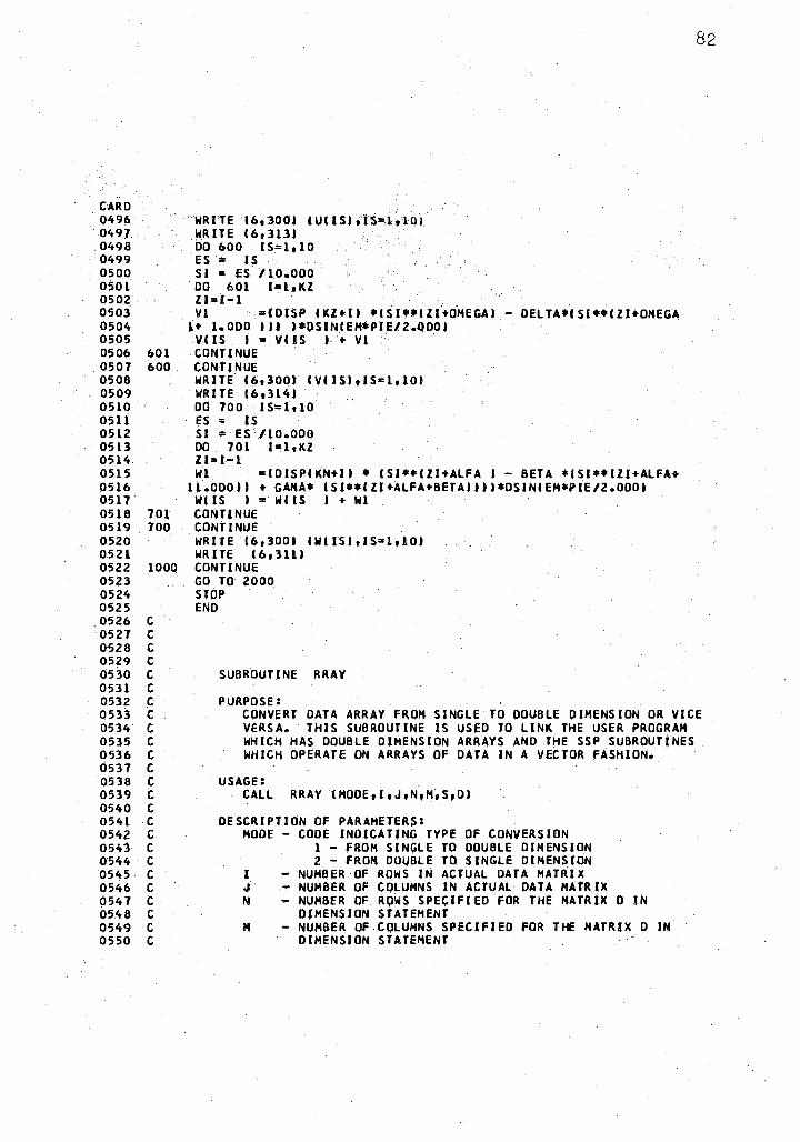
CARD 0496 0497. 0498 0499 0500 0501 0502 0503 0504 0505 0506 601 0507 600 0508 0509 0510 0511 0512 05l3 0514 0515 0516 0517 0518 701 0519 700 0520 0521 0522 1000 0523 0524 0525 0526 C 0527 C 0528 C 0529 C 0530 C 0531 C 0532 C 0533 C 0534 C 0535 C 0536 C 0537 C 0538 C 053.9 C 0540 C 0541 C 0542 C 0543 C 0544 C 0545· C 0546 C 0547 C 0548 C 0549 C 0550 C
WRITE 16,3001 lUClShlS=l~l()i WRITE I 613131 DO 600 IS=l,10 ES = IS SI = ES / 10.000 00 601 1=1.,KZ Zl=l-1 Vl ~,01sP CKZ•II •cs1••cz1•0MEGAI - OELTA•cs1••CZl•OMEGA
U 1.000 I U l*OSINCEH*PU:/2.QOOI V CIS I = V C IS I • V 1 CONTINUE CONTINUE WRITE 16,3001 CVCISl,IS=l,101 WRITE C 6 ,3141 DO 700 · IS=l,10 es = as SI = ES /10.000 DO 701 1=1,KZ Zl=l-1 Wl =CDISPCKN+II • CSl••CZl+ALFA I - BETA *(Sl••CZl+ALFA+
lt.OOOII • GAHA• CSl••CZl•ALFA+BETAllll•OSINCEM•PtE/2.0001 WC IS I = WC IS I + Wl CONTINUE CONTINUE WRITE (6 1 3001 CWCISl,IS=l,10) WR ITE I 6, 3111 CONTINUE GO TO 2000 STOP END
SUBROUTINE RRAY
PURPOSE:
82
CONVERT DATA ARRAY FROH SINGLE TO DOUBLE DIMENSION OR VICE VERSA. THIS SUBROUTINE IS USED TO LINK THE USER PROGRAH WHICH HAS DOUBLE DIMENSION ARRAYS AND THE SSP SUBROUTINES WHICH OPERATE ON ARRAYS OF DATA IN A VECTOR FASHION.
USAGE: CALL RRAY (MODE,1,J,N,M,S,DI
DESCRIPTION OF PARAMETERS: HOOE - COOE INDICATING TYPE OF CONVERSION
1 - FROM SINµLE TO DOUBLE DIMENSION 2 - FROM DOUBLE TO SINGLE DIMENSION
I NUMBER OF ROWS IN ACTUAL DATA MATRIX J • NUMBER OF COLUMNS IN ACTUAL DATA MATR ~X N NUMBER OF ROWS SPE~IFIED FOR THE MATRIX O IN
DIMENSION STATEMENT H NUMBER OF COLUMNS SPECIFIED FOR THE MATRIX DIN
DIMENSION STATEMENT
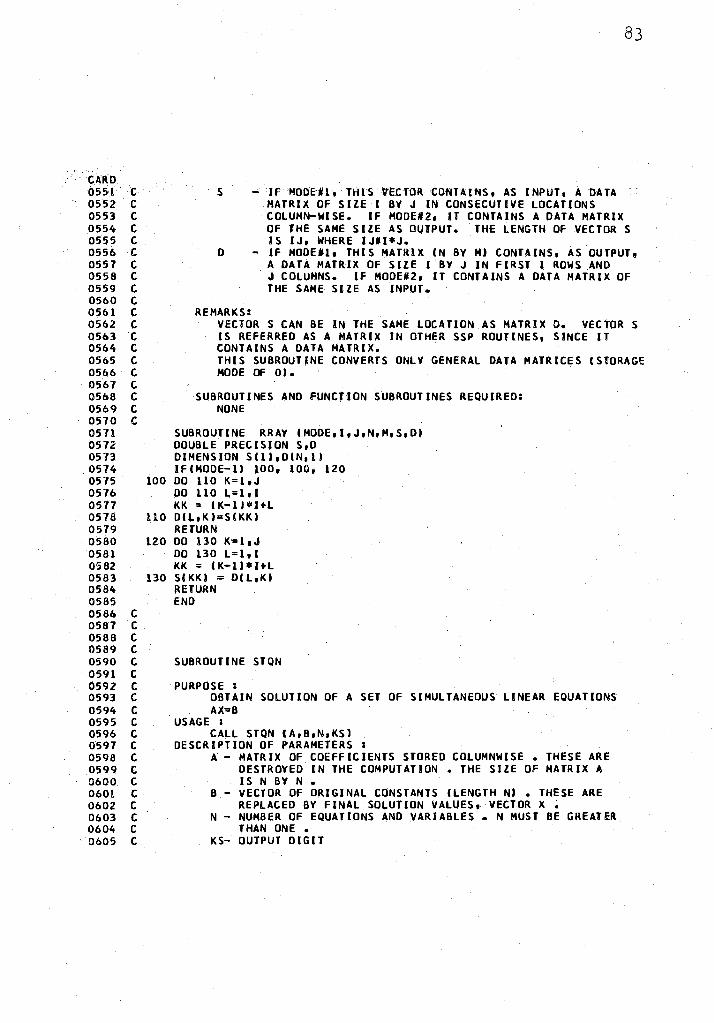
CARD 0551 C 0552 C 0553 C 0554 C 0555 C 0556 C 0557 C 0558 C 0559 C 0560 C 0561 C 0562 C 0563 C 0564 C 0565 C 0566 C 0567 C 0568 C 0569 C 0570 C 0571 0572 0573 0574 0575 100 0576 0577 0578 110 0579 0580 120 0581 0582 0583 130 0584 0585 0586 C 0587 C 0588 C 0589 C 0590 C 0591 C 0592 C 0593 C 0594 C 0595 C 0596 C 0597 C 0598 C 0599 C 0600 C 0601 C 0602 C 0603 C 0604 C 0605 C
83
s - If MOOEn. n:us VECTOR 'CONTAINS, AS INPUT, A DATA MATRIX OF SIZE I BY J IN CONSECUTIVE LOCATIONS COLUMN-WISE. IF MODE#2, IT CONTAINS A DATA MATRIX OF THE SAHE SIJE AS OUTPUT. THE LENGTH OF VECTORS IS IJ, WHERE JJ#l*J.
D - If HODEtl, THIS MATRIX IN BY HI CONTAINS, AS OUTPUT 9
REMARKS:
A DATA MATRIX OF SIZE I BY J IN FIRST I ROWS AND J COLUMNS. IF HODE#2, IT CONTAINS A DATA MATRIX OF THE SAHE SIZE AS INPUT.
VECTORS CAN BE IN THE SAHE LOCATION AS MATRIX D. VECTORS IS REFERRED AS A MATRIX IN OTHER SSP ROUTINES, SINCE IT CONTAINS A DATA MATRIX. THIS SUBROUTINE CONVERTS ONLY GENERAL DATA MATRICES ISTORAGE MODE OF OJ.
SUBROUTINES AND FUNCJION SUBROUTINES REQUIRED: NONE
SUBROUTINE RRAY (HODE,1,J,N,H,S,D) DOUBLE PRECISION S,D DIMENSION S(ll,D(N,11 IF (HOOE-II 100, 100, 120 DO 110 K=l ,J DO 110 L=l, I KK = ( K-1 J * HL DIL,;KJ=SIKKJ RETURN DO 130 K=l ,J DO 130 L=l, 1 KK = CK-ll*HL SIKKI = D(L,KI RETURN END
SUBROUTINE STQN
PURPOSE: OBTAIN SOLUTION OF A SET OF SIMULTANEOUS LINEAR EQUATIONS AX-=B
USAGE : CALL STQN IA,B,N,KSI
DESCRIPTION OF PARAMETERS A - MATRIX OF COEFFICIENTS STORED COLUHNWJSE. THESE ARE
DESTROYED IN THE COMPUTATION • THE SIZE OF MATRIX A IS N BY N.
B - VECTOR OF ORIGINAL CONSTANTS (LENGTH NI • THESE ARE REPLACED BY FINAL SOLUTION VALUES, VECTOR X ~
N - NUH8ER OF EQUATIONS AND VARIABLES • N HUST BE GREATER THAN ONE.
KS- OUTPUT DIGIT
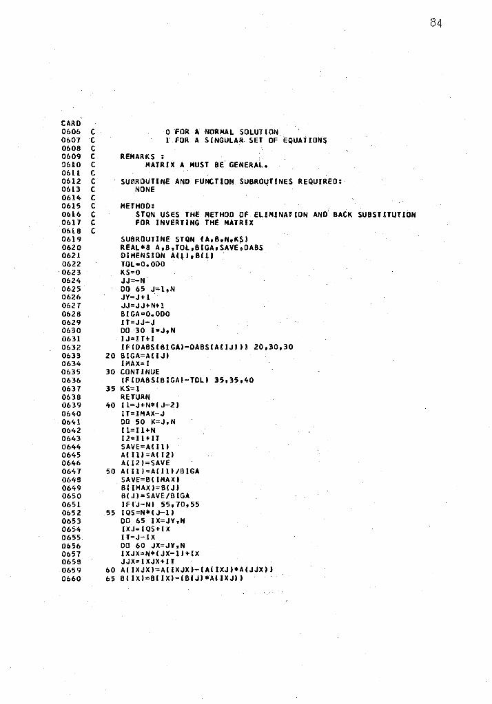
CARD 0606 C 0607 C 0608 C 0609 C 0610 C 0611 C 0612 C 0613 C 0614 C 0615 C 0616 C 0617 C 0618 C 0619 0620 0621 0622 0623 0624 0625 0626 0627 0628 0629 0630 0631 0632 0633 0634 0635 0636 0637 0638 0639 0640 0641 0642 0643 0644 0645 0646 0647 0646 0649 0650 0651 0652 0653 0654 0655 0656 0657 0656 0659 0660
0 "FOR A NORMAL SOLUTION l FOR A SINGULAR SET OF ~QUATIONS
REMARKS MATRIX A HUST BE' GENERAL.
SUBROUTINE AND FUNCTION SUBROUTINES REQUIRED: NONE
METHOD: I
STQN USES THE METHOD OF ELIMINATION AND BACK SUBSTITUTION FOR INVERTING THE MATRIX
SUBROUTINE STQN (A,B,N,KS) REAL*6 A,B,TOL,BIGA,SAVEoDABS DIMENSION AC~),B(ll TOL=O.ODO KS=O JJ=-N DO 65 J=l,N JY=J+l . JJ=JJ+N+l BIGA=O.ODO IT=JJ-J DO 30 l=J,N IJ=IT+I IFIDABSCBIGA)-DABSCAlfJl)I 20,30,30
20 BIGA=ACIJ) IMAX= I
30 CONTINUE IFIDABSIBIGA)-TOLI 35,3~,40
35 KS=l RETURN
40 Il=J+N•IJ-2) IT=IHAX-J DD 50 K=J, N ll=ll+N 12=1 l + IT SAVE=A( 11) ACIU=All2) ACl21=SAVE
50 ACll)=Alll)/BIGA SAVE=BIIHAXI BIIHAX)=BIJ) BIJl=SAVE/BIGA IFIJ-N) 55,70,55
55 I QS=N• I J-1) DO 65 IX=JY,N IXJ=IQS+IX IT=J-1 X DO 60 JX=JY,N IXJX=N•IJX-l)+IX JJX=IXJX+IT
60 AIIXJXl=ACIXJX)-CAIIXJ)•A(JJXI) 65 B(IX)=BCIX)-IBIJ)*AIIXJ))
84
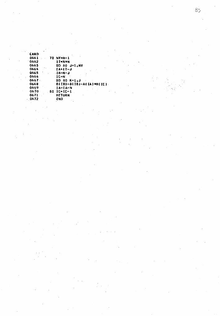
CARD 0661 0662 0663 0664 0665 0666 0667 0668 0669 0670 0671 0672
70 NY=N-1 IT=N•N DO 80 J=leNY IA=IT-J IB=N-J JC=N DO BlO K=lwJ B(IBl=8CIBl-ACIAl•BIICJ I A=I A-N
80 JC=JC-1 RETURN END
VITA ~:,
Ashok Nain
Candidate for the Degree of
Doctor of Philosophy
Thesis~ AN APPROXIMATE ANALYSIS OF OPEN NONCIRCUL.AR CYLINDRICAL SHELLS
Major Field~ Engineering
Biographical~
Personal Data~ Born March 28, 1941, in Karachi 1
Pakistan? the son of LokumaJ. and Parvati Naino
Educationi Attended St. Peter's High School, J?anchgani, India, and passed the University of Cambridge School Leaving Certificate Examination in December~ ·1958Q Joined St. Xavier's College, Calcutta, and passed the Intermediate Science Examination in March, 1960. Received the Degree of Bachelor of Engineering (Civi.l) from Calcutta University in February, 1964. Received the Degree of Master of Science from Illinois Institute of Technologyt Chicago 1 Illinois~ in June 1 19660 Completed requirements for the Degree of Doctor of Philosophy from Oklahoma State University, Stillwater, Oklahoma, in May~ 1970.
Professional Experience~ Engineering design and calculations for Westenhoff and Novick Inc., Chicago~ Illinois 9 Summer 1965. Structural Design Engineer for Skidmore 1 Owings, and Merrill~ Chicago~ Illinois, from January, 1966 1 to September, 19660 Graduate Teaching Assistant at Oklahoma State University from September 1 1968 1 to the present timeo Member of American Concrete Institute and American Society of Civil Engineersb.