an assessment of the bearing capacity of calcareous and ... · an assessment of the bearing...
TRANSCRIPT

INTERNATIONAL JOURNAL FOR NUMERICAL AND ANALYTICAL METHODS IN GEOMECHANICS, VOL. 13, 19-36 (1 989)
AN ASSESSMENT OF THE BEARING CAPACITY OF CALCAREOUS AND SILICA SANDS
S. K. YEUNG AND J. P. CARTER
School of Civil und Mining Engineering, University of Sydney, NSW 2006. Austruliu
SUMMARY
A spherical cavity expansion model has been used to study the bearing capacity of foundations on calcareous and silica sands. Two constitutive models have been used to represent each sand: an elastoplastic, collapse- softening model, and a computationally simpler, elastic/perfectly plastic material. The predictions of the limit pressures for spherical cavity expansion are compared with laboratory data on the bearing capacities obtained from model footing tests. It is shown that the numerical predictions of the limit pressures correlate well with the experimental values of bearing capacity, particularly at higher effective overburden pressures.
INTRODUCTION
Calcareous sands are abundant in coastal areas and continental shelves of the tropical and temperate regions of the world. They are frequently found in areas where offshore oil is being produced. A review of the available data on their engineering behaviour by Poulos’ indicates that the geotechnical properties of calcareous sands are different from those of silica sands. In particular, calcareous sands are frangible and known to undergo considerable volume reduction as a result of ‘crush-up’ when subject to compressive stress. This unusual feature tends to have a major effect on the behaviour of foundations in these materials.
Data from triaxial tests performed on calcareous materials show that they can develop very high interparticle friction.2 However, measurements from tests on model-scale piles jacked into calcareous sand indicate that the average skin friction and the total frictional resistance developed along the lengths of the piles are Recent experimental work by Nauroy and LeTirant4 and by Noorany’ has established that the low shaft friction developed on piles driven into carbonate soils is caused by low radial effective stresses developed at the soil-pile interface. Small-scale model footing tests also reveal that the bearing capacity of calcareous sands is significantly less than that of silica sands. Predictions of bearing capacity based on classical theories are often much higher than the actual experimental valueQ similar findings have also been reported by other researchers (see e.g. References 7-9). It has been recognized that the crushing of calcareous sands is of fundamental importance and should be taken into account in any analysis of the axial capacity of piles and the end-bearing capacity of foundations in such material.
The mechanical behaviour of silica sands has been studied for some time, and it is well known that-unlike calcareous sands-they are generally dilatant materials, except when in a very loose condition or when subjected to very high confining pressures. Because of their dilatant nature, silica sands usually develop higher skin frictions and higher bearing capacities than calcareous sands at the same confining pressure (see e.g. Reference 6).
0363-9061 /89/010019-18$09.00 0 1989 by John Wiley & Sons, Ltd.
Received 9 March 1987 Revised I I May 1988
20 S. K . YEUNG AND J . P. CARTER
In this paper, the ultimate bearing capacity of footings on silica and calcareous sands is estimated using a spherical cavity expansion model. Predictions of the limit pressures during spherical cavity expansion are then compared with some laboratory measurements6 of bearing capacity to assess the applicability of the one-dimensional cavity expansion approach to the prediction of the static bearing capacity of calcareous and silica sands.
It is well known that the cavity expansion solutions provide reasonable estimates of ultimate end-bearing resistance in loose silica sand which may be moderately compressible. l o However, at any given level of effective stress, calcareous sands are usually more compressible than silica sands. One of the aims of the present work was to determine whether the cavity expansion approach for estimating ultimate bearing capacity remains valid for materials with these high levels of compressibility. A second and equally important aim was to assess whether a sophisticated constitutive model, described here as a collapse-softening model, is necessary to produce reliable estimates. In order to investigate this aspect, two different soil models were employed to determine the limit pressures for spherical cavity expansion. The more sophisticated of these two models is described in detail, and it is shown that numerical techniques are required in order to obtain the limit pressures when this type of material behaviour is assumed. The simpler elastoplastic model employes a Mohr-Coulomb yield criterion with a non-associated flow rule. Closed-form solutions for the limit pressures in this material have been presented previously.
CAVITY EXPANSION MODEL
In soil mechanics, the cavity expansion model was first used by Gibson" to estimate the end- bearing capacity of a deep foundation in clay, The approach is based on the work by Bishop et a1.13 and assumes that the resistance to deep penetration is of the same order of magnitude as that necessary for expanding a spherical cavity in the same medium. A similar technique was applied by LadanyiI4-l6 in studying the load carrying capacity of brittle materials and sensitive clays.
For cohesionless soils, Vesic" utilized spherical cavity expansion solutions as a basis for predicting the point resistance of piles. Based on observations in model and full-sized pile tests in silica sands, he introduced semi-empirical modifications to the cavity expansion solutions to obtain reasonable estimates of bearing capacity. From a series of spherical cavity expansion experiments and pile penetration tests on silica sand, Aboshi17 compared the limit pressure required to expand a spherical cavity indefinitely with the penetration resistance of a pile, and concluded that at high surcharge pressures, in excess of 300 kPa, the penetration resistance can be determined successfully from the spherical cavity limit pressure.
The 'strain path' method pioneered by Baligh18 has been applied to problems of deeply buried structures in which the pattern of deformation is analogous to that for steady state flow of soil past the embedded structure. He concluded that the distortions observed ahead of a pile are similar to those corresponding to a spherical cavity expansion. However, in the far field the cavity expansion theory significantly underestimates the deformations and strains.
The spherical cavity expansion model, although restricting the dependence of field variables (i.e. stress and displacement) to the radial co-ordinate only, can be very useful in studying foundation behaviour because the one-dimensional simplification yields an economical solution, even with the implementation of more complex soil models.
In the following section is described an elastoplastic model which attempts to reproduce the major features of the mechanical behaviour of sands. The procedures employed to determine the various model parameters are then outlined.

BEARING CAPACITY OF CALCAREOUS AND SILICA SANDS 21
CONSTITUTIVE MODEL FOR SAND
It is convenient to adopt a spherical co-ordinate system and to restrict attention to a dry soil medium. The components of effective stress, as shown in Figure 1 (compression positive), and total strain increment in this co-ordinate system are
(T’ =(a:, a;, and de = (ds,., ds,, dQT
Because of spherical symmetry,
@;=a; and ds,=ds4 (1) For the purpose of reproducing the stress-strain behaviour by an elastoplastic model, the total
strain increments de are taken to be the sum of an elastic component and a plastic component. The plastic strain increments are themselves further divided into a collapsing part and an expansive part, as suggested by Lade,” such that
de = dee + dEP, dEP = dec + ds” (2) where dee is the ‘recoverable’ elastic strain, de” is the irrecoverable collapsing strain and de” is the irrecoverable expansive strain. Figure 2 illustrates schematically the different components of the total strain that would occur if this ideal material were subjected to a conventional drained triaxial compression test.
Elastic strain
The elastic behaviour is assumed to be isotropic, and the elastic strain components are calculated by Hooke’s law. The variation of Young’s modulus E’ with the mean pressure a; is represented in the form of a power law similar to that proposed by Janbu:”
E’/Pa = k(&/P,)” (3) where k is the modulus number, n is the modulus exponent, a;=4(0; +o;+a;) and Pa is the atmospheric pressure, introduced to obtain a dimensionless equation. Poisson’s ratio is assumed to be constant, so the model will be non-conservative for elastic behaviour.2
0;
Figure 1 Stress components for spherical cavity expansion

22 S . K. YEUNG AND J. P. CARTER
Elastic S t ra in I i Plast ic Collapse
Figure 2. Schematic illustration of elastoplastic collapse and plastic expansive strain components in drained triaxial compression testing (after Reference 19)
Collapse strain
Carbonate sands have lower crushing strengths than do silica sands, and it has been suggested that the softer carbonate particles as well as the presence of large intraparticle voids may be the contributing factors in producing these low crushing strengths. The collapse of the carbonate grains is essentially ‘plastic’ in nature, i.e. the strains are irrecoverable.
In the soil model used here, it is assumed that the yield surface has a spherical cap with its centre at the origin of the principal stress space, similar to that proposed by Lade.” The yield criterion is defined as
Fc=I:+212 (4) where
I , =a; + a;+ 0; = 3a;, I , = -(a;cT; + a;a; + cT;a;) As the value of the function F, increases beyond its previously highest value, plastic collapse strain will be produced and the soil will work-harden isotropically, with the yield cap expanding symmetrically around the hydrostatic axis.
The collapse strain increments are computed using an associated flow rule,
dgc = 2Al,dd (5) The value of A& can be found from the work-hardening law, which relates the total plastic collapse work done per unit volume W, to the degree of hardening expressed by F,.

BEARING CAPACITY OF CALCAREOUS AND SILICA SANDS 23
The incremental plastic work done per unit volume during collapse, d W,, is calculated from
(6)
(7)
d W, = dT dEc
WcIPa = C (Fc/P,2 1" W, is related to F, through the following empirical expression, proposed by Lade:19
where C is the collapse modulus, m is the collapse exponent and Pa is the atmospheric pressure, expressed in the same units as W, and the other stress quantities.
By analogy with classical plasticity theory (see Reference 22), Adc can be written as
Ad, = d W, 12 F, (8) where d W, is the increment of plastic collapse work occurring during the increment of F,.
It is quite easy to show that d W, is given by
d WJPa = Cm [P,2/FC]'-" d [ F c / P , 2 ] (9) The plastic collapse strain increments can then be calculated from equations (9), (8) and (5), with known values of C, m and F,.
Expansive strain
The plastic expansive strain increments are computed using a strain-softening constitutive law. The shear failure surface for most cohesionless material is found to be curved, with the
instantaneous friction angle decreasing with confining pressure. In the present formulation a curved failure surface is postulated which, when expressed in terms of principal stresses a', and a;, is given by
F, = a', - N4 a; - 2c'J N4 = 0
where 1 + sin 4'
N - '- 1 -sin
and c' and 4' are the instantaneous values of cohesion and friction angle respectively.
by Davis,23 and the plastic potential G, is given by The plastic expansive strain components are related by a non-associated flow rule as suggested
(12) G, = a', - NJ,o ; - ~ c ' J N , = 0
where 1 + sin $'
N - J, - 1 -sin
and $' is the instantaneous angle of dilation. It is further assumed that y p can be used as a measure of softening, where
y P = & ? - 83 p (14)
y p is defined as the plastic shear strain for this spherical problem, and E P and E $ are the total plastic strain components corresponding to the directions of the principal stresses o', and a;. During cavity expansion, the radial component of stress will be the major principal stress and the circumferential component will be the minor principal stress.
24 S. K. YEUNG AND J. P. CARTER
For stress paths within both current yield loci, the behaviour is entirely elastic, and the size of the curved yield surface is defined by equation (10) with
and
where the values of 4’ are measured in degrees. Both elastic and plastic deformations occur when either of the two yield surfaces is activated
and the strength parameters c’ and 4’ decrease linearly with increasing plastic shear strain yp. This implies that the strength parameters of the material, cf and 4’, will decrease, even under isotropic compression. However, the onset of dilation is controlled entirely by the curved yield envelope. Shear failure takes place whenever Fp=O and the material dilates at a constant rate, i.e. the angle of dilation $‘ is constant. At a specified magnitude of the plastic shear strain y:, a residual state is reached after which the material has constant strength parameters, and there is no further plastic expansive volume change (dilation). Thus, during the softening period two conditions can be identified:
1. When 0 < y p < Y E , the instantaneous values of the strength parameters are given by c’ = c’ - (c‘ -
p p c:)YplY: tan #’ = tan 4; -(tan #b - tan 4:) yP/y:
*, = { Tnstant, Fp = 0 Fp<O
2. When y p 3 y:, the constant strength parameters are
c’ = cf
4‘ = 4; $ ‘ = O
The proposed elastoplastic stress-strain model has been developed specifically for the cavity expansion problem, where no rotation of principal stress directions occurs and where triaxial conditions prevail, i.e. o; = oj and c2 = E ~ . The model in its present form is not directly applicable to general three-dimensional stress conditions; a more general definition of the softening parameter y p would then be required.
In developing the model the aim has been to reproduce several important characteristics of calcareous sand, namely (1) non-linearity, (2) a curved failure envelope and post-peak strain softening, (3) stress dilatancy and (4) irrecoverable volume reduction as a result of grain crushing. In particular, the effects of volumetric crushing have been included directly by the use of a spherical yield cap (equation (4)) and indirectly through the influence of the overall plastic strain on the curvature of the shear yield surface (equations (10) and (17H22)). Because the behaviour of silica sand at high stresses in many respects resembles that of calcareous sand,24 it may be possible to use the same model to predict limit pressures for silica sand.
DERIVATION OF SOIL PARAMETERS
The complete description of the proposed model requires eight parameters to specify the collapse and softening response as well as the three elastic parameters for the material. All soil constants can be derived from isotropic compression tests and conventional drained triaxial compression
BEARING CAPACITY OF CALCAREOUS AND SILICA SANDS 25
tests with unloading-reloading cycles. Two types of sand were used by Chua6 in his experimental study of bearing capacity. One was a silica sand which came from the Sydney region, a fairly uniformly graded material. The calcareous sand used by Chua consisted mainly of uncemented grey sand grains. A summary of the main physical properties of each material is given in Table I. Unfortunately, a comprehensive series of tests which would allow a complete determination of the model parameters is not available for both materials. Some assumed values have thus been used in the analysis, and these are discussed below.
Elastic parameters
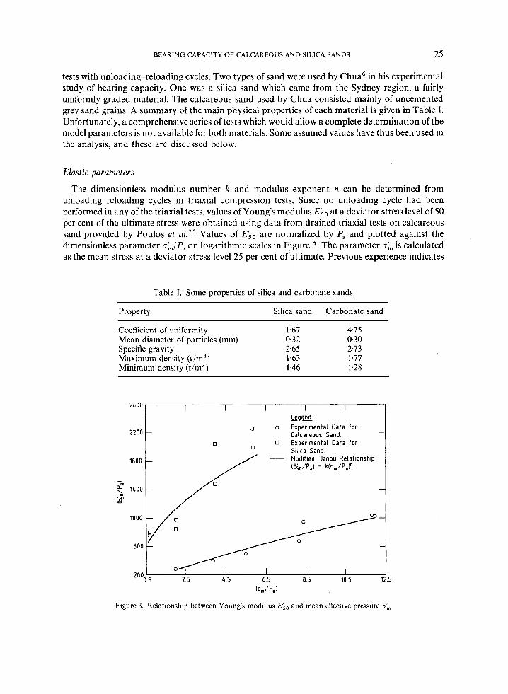
The dimensionless modulus number k and modulus exponent FI can be determined from unloading-reloading cycles in triaxial compression tests. Since no unloading cycle had been performed in any of the triaxial tests, values of Young's modulus E50 at a deviator stress level of 50 per cent of the ultimate stress were obtained using data from drained triaxial tests on calcareous sand provided by Poulos et aLZ5 Values of Ek0 are normalized by Pa and plotted against the dimensionless parameter &/Pa on logarithmic scales in Figure 3. The parameter o& is calculated as the mean stress at a deviator stress level 25 per cent of ultimate. Previous experience indicates
Table I. Some properties of silica and carbonate sands
Property Silica sand Carbonate sand
Coefficient of uniformity 1.67 475 Mean diameter of particles (mm) 0.32 0.30 Specific gravity 2.65 2.73 Maximum density (t/m3) 1.63 1.77 Minimum density (t/m3) 1.46 1.28
- d L w - m
2600 I I I I I I
2200
_ - Legend' 0 o Experimental Data for
Calcareous Sand.
Silica Sand
-
0 0 Experimental Data for 0
Modified 'Janbu Relationship __ (Ef,/PJ = k(o;/P,I"
1800 -
-
1000
600
2oo*.5 2.5 4 5 6.5 8.5 10.5 12.5 la; /Pa)
Figure 3. Relationship between Young's modulus E i 0 and mean effective pressure cr',,,
26 S. K. YEUNG AND J. P. CARTER
that, for dense sand, the unloading-reloading Young’s modulus may be 20 per cent greater than the corresponding value for primary loading.26 However, in the present study no adjustment has been made to account for this difference, and thus from Figure 3 the values of the dimensionless parameters k and n are found to be 165.22 and 0.73, respectively. By a simiIar procedure, the values of k and n for silica sand were found to be 828.13 and 0.46. At the same confining pressure, the Young’s modulus for calcareous sand is significantly lower than the corresponding value for silica sand. It should be borne in mind that, in the calculation of &,, k and n, any plastic components of the total strains have been assumed to be negligibly small.
The value of Poisson’s ratio for both materials has been found to be close to 0.3,27 and therefore this value has been adopted in the subsequent analysis.
Collapse parameters
Two parameters are required to compute the plastic collapse strains. The collapse modulus C and the exponent m can be determined by plotting the plastic work done during collapse, W,, and the yield function, F,, on logarithmic scales.
In order to separate plastic collapse strains from the plastic expansive strains, an isotropic compression test should be carried out, since this is the only loading condition for which it is certain that no expansive strain components are generated. However, such data are not available and so the collapse parameters were determined from the results of KO consolidation tests.
During the K , consolidation testing the plastic collapse strain components 8; and E ; were found to be small, and so have been ignored. Hence, the plastic collapse work done per unit volume, W,, is simply given by
W, = 1 a; d&E (23)
where E : = E ~ - E ~ , c l = A e / ( l + e , )
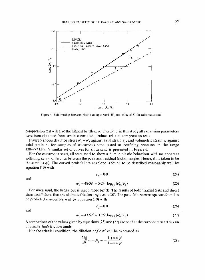
Ae being the change in voids ratio and en being the initial voids ratio. Figure 4 shows the relationship between log (W,/P,) and log (F,/P,2) for calcareous sand from
which the parameters C and m are found to be 0.00021 and 1.18 respectively. For comparison, the results for loose Sacremento River sand” are plotted as a dashed line on the same figure. The collapse parameters for calcareous sand are higher than for silica sand as the former material is more susceptible to crushing.
Only experimental data from a KO consolidation test on silica sand were available for deriving the collapse parameters. However, the test was carried out in the relatively low mean stress range of 20-375 kPa. Because the experimental data for the Sydney silica sand are limited, and because in the KO consolidation tests only very small collapse strains were measured, the silica sand was assumed to behave in a simple strain-softening fashion, and the effects of grain crushing were ignored; i.e. the stress-strain model for the silica sand is without a volumetric yield cap. Therefore, no collapse parameters are required.
Expansion parameters
Dilatant plastic behaviour is governed by the curved shear strength envelope as well as by the angle of dilation. Experimental studies on two clays by Law2* illustrate that when a soil displays strain-softening characteristics, its brittleness is related to the effective stress path during shearing. For any soil tested at a given effective consolidation pressure, the conventional drained triaxial
BEARING CAPACITY OF CALCAREOUS AND SILICA SANDS 27
Loglo (F,/P:l
Figure 4. Relationship between plastic collapse work W, and value of F, for calcareous sand
compression test will give the highest brittleness. Therefore, in this study all expansion parameters have been obtained from strain-controlled, drained triaxial compression tests.
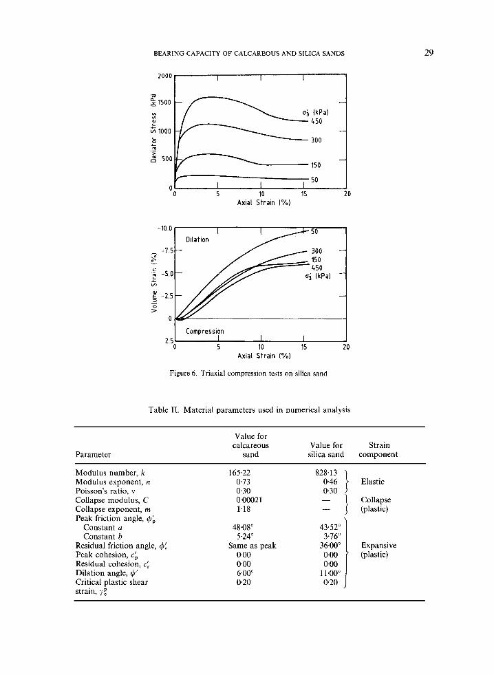
Figure 5 shows deviator stress 0; - a> against axial strain E ~ , and volumetric strain E, against axial strain c1 for samples of calcareous sand tested at confining pressures in the range 138-897 kPa. A similar set of curves for silica sand is presented in Figure 6.
For the calcareous sand, all tests tend to show a ductile plastic behaviour with no apparent softening, i.e. no difference between the peak and residual friction angles. Hence, 4; is taken to be the same as 4;. The curved peak failure envelope is found to be described reasonably well by equation (1 0) with
and c; = 0.0 (24)
(25) 4; = 48.08" - 5.24" log10 (cJP,)
For silica sand, the behaviour is much more brittle. The results of both triaxial tests and direct shear tests6 show that the ultimate friction angle 4; is 36". The peak failure envelope was found to be predicted reasonably well by equation (10) with
and
A comparison of the values given by equations (25) and (27) shows that the carbonate sand has an unusually high friction angle.
For the triaxial condition, the dilation angle t,h' can be expressed as

28 S . K. YEUNC AND J . P. CARTER
LOO0
- 3000 -
v1 m iu .k 2000 Ln
L 0 + .: 1000 W 0
0
I 1 I I
o j IkPa)
-
-
-
0 5 10 15 20 Axial S t ra in ( % I
-2 I I I I
2t Compression 1 3 3
0 5 10 15 20 Axial Stra in (%I
Figure 5. Triaxial compression tests on calcareous sand (after Reference 25)
where 6: and S: are the plastic expansive strain rates corresponding to the principal stresses a\ and a;. From the curves of E , versus 6; and 6: can be determined by subtracting the elastic and collapse components from the total strains according to equation (2). The dilation rate can then be calculated accordingly. At all confining pressures, $' was found to be nearly constant. For calcareous sand $' = 6", while for silica sand $' = 11".
The onset of a residual state is governed by 7;. However, it may be seen from the triaxial results that no test was carried out for long enough to establish the critical condition for calcareous sand, and so yX has arbitrarily been assigned a value of 20 per cent. In order to assess the sensitivity of the limit pressures in a spherical cavity expansion to the value of yz, parametric studies were performed in which yg was varied between 12 and 40 per cent. The maximum difference between these predicted limit pressures and those obtained with y ; = 20 per cent was only about 4 per cent. It is possible to deduce the value of yz for silica sand from the laboratory data, and this was found to be y = 20 per cent.
The values for all parameters required for the numerical analysis are summarized in Table 11.
FINITE ELEMENT ANALYSIS
A scheme for the numerical solution of the cylindrical and spherical cavity expansion problems has been proposed by Carter and Y e ~ n g , ' ~ and a computer program, FEACE, has been developed
BEARING CAPACITY OF CALCAREOUS AND SILICA SANDS 29
a Y 1500 cx I
Y) v) W L
~ 1 0 0 0 L
c 0
m > .-
500
(kPa) 450
300
150
. 50
- 0 5 10 15 Axial Strain ( % I
I Comoression I 0 5 10 15 20
Axial Strain (%)
Figure 6. Triaxial compression tests on silica sand
Table IT. Material parameters used in numerical analysis
Parameter
Value for calcareous Value for Strain
sand silica sand component
Modulus number, k Modulus exponent, It Poisson's ratio, v Collapse modulus, C Collapse exponent, m Peak friction angle, 6;
Constant a Constant b
Residual friction angle, 6: Peak cohesion, cb Residual cohesion, c: Dilation angle, $' Critical plastic shear strain,
165.22 0.73 0.30 0.0002 1 1.18
48.08" 5.24"
0.00 0.00 6.00" 0.20
Same as peak
828.13 0.46 } Elastic
Collapse (plastic)
4352" 3.76"
0.00 11.00" 020

30 S. K . YEUNG AND J. P. CARTER
and used in this analysis to estimate the limit pressure corresponding to spherical cavity expansion in a collapse-softening material.
The matrix equation relating the stress increments do' to the strain increments d s has the form
do' = DdE (29) where D is the elastoplastic material matrix. An incremental procedure developed by Lade and Nelson3' is used to formulate D when the spherical yield cap and the curved failure surfaces are activated simultaneously.
In the analysis, the initial stress condition before cavity expansion was assumed to be homogeneous and isotropic in order to preserve spherical symmetry. In the footing experiments of Chua,6 the sand was initially one-dimensionally consolidated under an effective overburden pressure a;,. The value of the initial isotropic effective stress Po used in the analysis was related to the effective overburden pressure used in the experiments by
p, = a;, = a;, = a;, = $( 1 + 2K,) a:,
where the coefficient of lateral earth pressure was approximated by K O = 1 -sin 4;. The choice of initial cavity radius a, does not affect the ultimate limit pressure, and a unit radius
was used in all computations. The analysis of cavity expansion was carried out by specifying radial displacements incrementally at the cavity wall, and the finite element equations were solved using a tangent stiffness approach. Parametric studies were performed to determine the number of elements and the step size required to model the problem under consideration. Typically, the mesh was made up of 90 elements with nodes-located at the interfaces between all elements and at the innermost boundary, i.e. the cavity wall. If the nodes are numbered consecutively from the cavity wall outwards, then the radius of the ith node is given by
ri = a,( 1.06)'-
An elastic spring element was used at the outer boundary to represent the correct stiffness of the infinite region of elastic material beyond the last node in the mesh.
The calcareous sand is relatively soft, and 1000 increments were used to produce a unit radial displacement at the cavity wall; this was sufficient to keep the maximum drift of the stress state of any plastic element from the curved yield surface at 3 per cent. For the stiffer silica sand, the step size had to be ten times smaller in some analyses in order to achieve the same degree of accuracy. To estimate the limit pressure, the analysis was allowed to continue for long enough for a pressure asymptote to be identified. For the materials under consideration, it was found that an asymptote could be identified accurately when the cavity had been expanded to about five times its original radius.
MODEL FOOTING EXPERIMENTS
Details of the model footing experiments have been given by Chua,'j and summarized by Poulos and c o - ~ o r k e r s ; ~ ~ , 32 only features relevant to this study are described here.
A uniform bed of sand was prepared in a cylindrical vessel, of 305 mm internal diameter and 229 mm deep, with drainage provided at both the top and bottom surfaces. The rough footing was circular with a diameter of 25 mm. After the apparatus was assembled, the desired overburden pressure a:, was applied and the soil allowed to consolidate. The footing was then loaded statically to failure at a rate slow enough to ensure fully drained conditions. A total of 44 tests were carried out, of which 23 were in calcareous sand. All tests were carried out with the loading stress- controlled.
BEARING CAPACITY OF CALCAREOUS AND SILICA SANDS 31
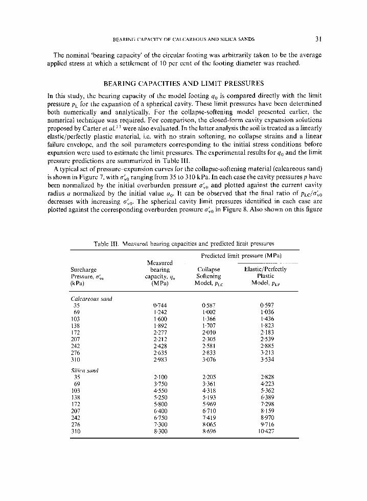
The nominal 'bearing capacity' of the circular footing was arbitrarily taken to be the average applied stress at which a settlement of 10 per cent of the footing diameter was reached.
BEARING CAPACITIES AND LIMIT PRESSURES
In this study, the bearing capacity of the model footing qo is compared directly with the limit pressure p L for the expansion of a spherical cavity. These limit pressures have been determined both numerically and analytically. For the collapse-softening model presented earlier, the numerical technique was required. For comparison, the closed-form cavity expansion solutions proposed by Carter et al.' were also evaluated. In the latter analysis the soil is treated as a linearly elastic/perfectly plastic material, i.e. with no strain softening, no collapse strains and a linear failure envelope, and the soil parameters corresponding to the initial stress conditions before expansion were used to estimate the limit pressures. The experimental results for q, and the limit pressure predictions are summarized in Table 111.
A typical set of pressure-expansion curves for the collapse-softening material (calcareous sand) is shown in Figure 7, with aLo ranging from 35 to 3 10 kPa. In each case the cavity pressures p have been normalized by the initial overburden pressure oko and plotted against the current cavity radius a normalized by the initial value a,. It can be observed that the final ratio of pLc/aLo decreases with increasing a:,. The spherical cavity limit pressures identified in each case are plotted against the corresponding overburden pressure oho in Figure 8. Also shown on this figure
Table 111. Measured bearing capacities and predicted limit pressures
Predicted limit pressure (MPa) - . Measured
Surcharge bearing Collapse Elastic/Perfectly Pressure, a:, capacity, qo Softening Plastic (k Pa) (MPa) Model, pLC Model, pLP
Calcareous sand 35 69
103 138 172 207 242 276 310
Silica sand 35 69
103 138 172 207 242 276 310
0.744 1.242 1.600 1.892 2.277 2.212 2.428 2.635 2.983
2.100 3.750 4.550 5.250 5.800 6.400 6.750 7.300 8.300
0.587 1.002 1.366 1.707 2.010 2.305 2.581 2.833 3.076
2.205 3.361 4.3 18 5.193 5.969 6.7 10 7.419 8.065 8.696
0.597 1.036 1.436 1.823 2.183 2539 2.885 3.213 3.534
2.828 4.223 5.362 6.389 7.298 8.159 8.970 9.7 16
10.427

32 S . K. YEUNG AND J. P. CARTER
18 I I I I I I I I I
Figure 7.
0 - >
\ a
4 ::1 2 0
310 (kPa1 I ~
0 1 2 3 4 5 6 1 0 9 a/a,
Predicted pressure-expansion curves for collapse and strain-softening material (calcareous sand)
(a f te r Chua (1983116
Collapse-Sof tening Model
Perfectly-Plastic Model
-0- Predictions based on
0 40 80 120 160 200 2 4 0 280 320 Surcharge Pressure a;o IkPal
Figure 8. Comparison ofcomputed limit pressures and measured bearing capacities from model footing tests in calcareous sand
are the measured bearing capacities from the model tests in calcareous sand and the spherical cavity limit pressures obtained with the perfectly plastic model. The load carrying capacity of carbonate sand generally increases with c&, but may be approaching a limiting value at high surcharge pressure. The experimental results in the range of overburden pressure between 200 and 280 kPa fall slightly below the general trend. However, it is difficult to decide whether this is

BEARING CAPACITY OF CALCAREOUS AND SILICA SANDS 33
simply an experimental scatter or whether it results from a change in failure mode as the surcharge pressure increases.
At low overburden pressures, the limit pressures predicted with the collapse-softening constitutive model are about 20 per cent below the actual bearing capacities, while good agreement is obtained for the tests carried out at o:,, greater than 200 kPa. However, the analytical predictions based on the simpler elastic/perfectly plastic model overestimate the bearing capacity by as much as 18 per cent at the higher overburden pressures.
Figure 9 shows a comparison between the measured bearing capacities and the predicted limit pressures for a spherical cavity in the silica sand. Again, it is noted that at low overburden pressure (less than about 160 kPa), the bearing capacity is underestimated by the numerical predictions of limit pressure. At high overburden pressures, the numerical results based on the proposed softening model give slightly higher estimates. However, the limit pressures obtained with the elastic/perfectly plastic model are as much as 26 per cent higher than the actual measured bearing capacity values.
The results of this study also reveal the importance of using a constitutive model with a realistic representation of the crushing characteristics of the granular carbonate materials. At low overburden pressure the limit pressures predicted by the two models are in good agreement. The primary factor influencing the end-bearing capacity at low overburden pressures is the plastic shear dilatancy characteristics of the soil. Thus the simpler perfectly plastic model may be used with an appropriate dilation angle to provide a preliminary estimate of the end-bearing capacity at low effective surcharge pressures. However, when crushing becomes important at higher overburden pressures, the limit pressures predicted by the more complex collapse-softening model are in better agreement with the measured bearing capacities.
In practice it is possible to improve the agreement between the measured bearing capacities at the higher surcharge pressures and the predictions obtained with the simpler perfectly plastic model by adjusting model parameters, but, as explained below, this is somewhat artificial and unsatisfactory from a physical viewpoint. Some improvements in the numerical agreement could
)r c p U
c ._ E ._ 2
0
I I I I I I I - - Legend: Experimental Results. Q
(after Chua (198311''
Collapse-Sof tening Model
Perfectly-Plastic Model
-
-0- Predictions based on
- -+ Predictions based on
80 120 160 200 240 280 Surcharge Pressure trio lkPaf
Figure 9. Comparison of computed limit pressures and measured bearing capacities from model footing tests in silica sand
34 S . K . YEUNG AND J. P. CARTER
be obtained by specifying a lower value of dilation angle in the simpler model of the calcareous material, specifically t,b = 4". In this approach, with this simpler model, the effect of crushing under isotropic loading is ignored, and all plastic volume change is controlled by the shear yield criterion alone. While this may give good numerical agreement between limit pressures and measured bearing capacities, from a physical point of view the simpler model is clearly inadequate, being unable to predict volumetric collapse under an increasing purely isotropic stress, i.e. in the absence of any shear stress.
The difference between the results obtained with the collapse-softening model and the perfectly plastic model can lie inside the range of variation that can be generated by modest changes of the material parameters. With both material models the parameters that have greatest influence on the predictions of the limit pressures are those that describe the relative stiffness and volume change behaviour of the soil, E'/a:, and t,b', and obviously accurate estimates of these parameters are required if reliable predictions are to be made with either model. For example, with the simpler perfectly plastic model described above a variation of 5" in the dilation angle results in changes in the predicted limit pressures that are of the order of f 20 per cent for the calcareous sand and f 25 per cent for the silica sand. This indicates that typically the angle of dilation I)' should be estimated to better than 5" accuracy.
It is important to recognize that the comparison of theoretical and experimental results outlined above is relevant only to the definition of 'bearing capacity', and the quality of agreement between the predicted limit pressure and the measured bearing capacity will vary with the definition of that bearing capacity. Here and in the work of Chua6 the bearing capacity has been defined as the average footing pressure to cause a settlement equal to 10 per cent of the footing diameter. This definition of bearing capacity is, of course, arbitrary. Since the soil can be expected to be stiffer before failure when the overburden pressure is high, a greater proportion of the ultimate resistance may be mobilized at 10 per cent displacement under high overburden pressure than would be mobilized in a more lightly consolidated soil at the same displacement.
For a further assessment of the correlation of the predicted limit pressures during spherical cavity expansion with measured bearing capacities q,, the latter have been normalized by the numerical limit pressures pLc and plotted against the effective overburden pressures ob0 in Figure 10 for both sands. A similar trend is observed with the two types of sand, a better correlation being observed with increasing overburden pressure. At higher overburden pressures the computed limit pressures generally lie within 10 per cent of the experimental values. These results show that the spherical cavity expansion model provides a reasonable prediction of bearing capacity and is particularly useful in determining the bearing capacity of deep foundations.
CONCLUSIONS
A spherical cavity expansion model has been used to study the bearing capacity of foundations on calcareous and silica sands. Two constitutive models have been used to represent each sand, an elastoplastic, collapse-softening model and a simpler elastic/perfectly plastic material. The predictions of the limit pressures for spherical cavity expansion have been compared with laboratory data on bearing capacities obtained from model footing tests. The numerical predictions of limit pressure are in good agreement with the experimental values of bearing capacity, particularly at higher effective overburden pressures (greater than about 200 kPa) and when volumetric collapse is correctly included in the material model. At lower overburden pressures (less than about 200 kPa for the calcareous sand), where the tendency for volume reduction is not great, reasonable estimates of bearing capacity were found using the simpler

BEARING CAPACITY OF CALCAREOUS AND SILICA SANDS 35
Legend:
0 Silica Sand
- u o Calcareous Sand
cr" 1.20
__I a \
- 0
Surcharge Pressure a;, IkPa)
Figure 10. Accuracy of the spherical cavity expansion model in predicting the bearing capacity of sand
elastoplastic soil model. Calculations carried out in this case had the attraction and convenience of simple substitution into a closed-form expression.
In view of the difficulties associated with the finite element calculation of collapse loads for two- and three-dimensional problems in complex materials (see e.g. Reference 33), the simpler one- dimensional cavity expansion model appears to be of some practical use in investigating the bearing capacity of deep foundations in both highly compressible and dilatant soils.
The numerical results presented in this work were all evaluated using a one-dimensional finite element program operating on a personal computer. At the very least the engineering approach presented here might be used for the preliminary design of end-bearing foundations in carbonate sands. The extension of the method to allow prediction of ultimate capacities in cemented carbonate deposits may require the use of even more sophisticated constitutive models, but it is expected that the technique for spherical cavity expansion will remain valid. Work in this area is currently in progress.
ACKNOWLEDGEMENTS
The work described in this paper forms part of a project investigating the behaviour of offshore foundations, which is supported by a grant from the Australian Research Grants Commision. The first author is supported by a University of Sydney Research Scholarship.
REFERENCES
1. H. G. Poulos, 'A review of the behaviour and engineering properties of carbonate soils', Research Report No. R381,
2. I. Noorany, 'Friction of calcareous sands', Report, San Diego State University, CA, 1982. 3. G. S. Young 'An investigation of pile skin friction in Bass Strait carbonate sand', M. Eng. Sc. Thesis, University of
University of Sydney, 1980.
Sydney, 1983.

36 S. K. YEUNG AND J. P. CARTER
4. J. F. Nauroy, and P. LeTirant, ‘Model tests of piles in calcareous sands’, in Proc. Conf. on Geotechnical Practice in Offshore Engineering ASCE, 1983, pp. 356-369.
5. I. Noorany, ‘Side friction of piles in calcareous sands’, in Proc. 11 th Int. Conf. on Soil Mechanics and Foundation Engineering, Vol. 4, San Francisco, CA, 1985, pp. 1611-1614.
6. E. W. Chua, ‘Bearing capacity of shallow foundations in calcareous sand’, M. Eng. Sc. Thesis, University of Sydney, 1983.
7. J. Angemeer, E. Carlson and J. Klick, ‘Techniques and results of offshore pile loading testing in calcareous sand’, in Proc. 5th Annual OTC Conf., Vol. 2, Houston, TX, Paper OTC 1894, pp. 677-692.
8. J. Angemeer, E. Carlson, S. Stroud and M. Kurzeme, ‘Pile loading test in calcareous soils conducted in 400 feet of water from a semi-submersible exploration rig’;in Proc. 7th Annual OTC Conf., Vol. 2, Houston, TX, Paper OTC 2311,
9. R. N. Dutt and A. P. Cheng, ‘Friction response of piles in calcareous deposits’, in Proc. 16th Annual OTC Conf., Vol. 3,
10. A. S. Vesic, ‘Design of pile foundation’, National Co-operative Highway Research Program, Synthesis of Highway
11. J. P. Carter, J. R. Booker and S. K. Yeung, ‘Cavity expansion in cohesive, frictional soils’, Geotechnique, 36, 349-358
1975, pp. 657-670.
Houston, TX, 1984, pp. 527-534.
Practice 42, Transportation Research Board, Washington, DC, 1977.
(1986). 12. 13. 14.
15.
16.
17.
18.
19.
20.
21.
22. 23.
24.
25.
26.
27. 28. 29.
30.
31.
3 2.
33.
\ - -
R. E. Gibson, ‘Discussion’, J . Inst. Civil Eny., 34, 382-383 (1950). R. F. Bishop, R. Hill and N. F. Mott, ‘The theory ofindentation and hardness test’, Proc. Phys. SOC., 57,147-159 (1945). B. Ladanyi, ‘Failure mechanism of rock under plate load’, in Proc. 1st Congr. on Rock Mechanics, Vol. 1, ISRM, Lisbon, 1966, pp. 415420. B. Ladanyi, ‘Rock failure under concentrated loading’, in Basic and Applied Rock Mechanics, (K. E. Gray, Ed.), AIME, New York, 1972, pp. 363-387. B. Ladanyi, ‘Bearing capacity of deep footings in sensitive clay’, in Proc. 8th Int. Conf. on Soil Mechanics and Foundation Engineering, Vol. 2.1, Moscow, 1973, pp. 159-166. H. Aboshi, ‘Cavity expansion experiment in silica sand’ (in Japanese), in Proc. 13th National Conf. on Soil Mechanics and Foundation Engineering Japan, 1978, pp. 777-780. M. M. Baligh, ‘The strain path method in geotechnical engin,eering’, Publication R 8 4 4 1 , Massachusetts Institute of Technology. P. V. Lade, ‘Elasto-plastic stress-strain theory for cohesionless soil with curved yield surfaces’, Int. J . Solids Struct., 13,
N. Janbu, ‘Soil compressibility as determined by oedometer and triaxial tests’, in Proc. European Conf. on Soil Mechanics and’ Foundation Engineering Vol. 1, Wissbaden, Germany, 1963, pp. 19-25. M. Zytynski, M. F. Randolph, R. Nova and C. P. Wroth, ‘On modelling the unloading-reloading behaviour of soils’, Int. j . numer. anal. methods geomech., 2, 87-94 (1978). R. Hill, The Mathematical Theory of Plasticity, Oxford University Press, London, 1950. E. H. Davis, ‘Theory of plasticity and the failure of soil masses’, in Soil Mechanics-Selected Topics, (I. K. Lee, Ed.), Butterworths, London, 1968, pp. 341-380. A. S. Vesic and G. W. Clough, ‘Behavior of granular materials under high stresses’, J . Soil Mech. Foundation Div.
H. G. Poulos, M. Uesugi and G. S. Young, ‘Strength and deformation properties of Bass Strait carbonate sands’, Geotech. Eng., 13, 189-211 (1982). J. M. Duncan, ‘Hyperbolic stress-strain relationships’, in Proc. Workshop on Limit Equilibrium, Plasticity and Generalized Stress-Strain in Geotechnical Engineering, McGill University, Montreal, 1980, pp. 443460. T. S. Hull, Private Communication, 1986. K. T. Law, ‘Effect of stress path geometry on soil brittleness’, Geotechnique, 31, 279-287 (1981). J. P. Carter and S. K. Yeung, ‘Analysis of cylindrical cavity expansion in strain-weakening material’, Computers Geotech. 1 , 161-180 (1985). P. V. Lade and R. B. Nelson, ‘Incrementalization procedure for elasto-plastic constitutive model with multiple, intersecting yield surface’, Int. j . numer. anal. methods geomech., 8, 31 1-323 (1984). H. G. Poulos and E. W. Chua, ‘Bearing capacity of foundations on calcareous sand’, Research Report No. 515, University of Sydney, 1986. H. G. Poulos, E. W. Chua and T. S. Hull, ‘Settlement of model footings on calcareous sand‘, Research Report No. 490, University of Sydney, 1984. S. W. Sloan, ‘Numerical analysis of incompressible and plastic solids using finite elements’, Ph.D. Thesis, University of Cambridge, 1981.
1019-1035 (1977).
(ASCE) , 94, 661-688 (1968).