an automated railway system
TRANSCRIPT
1 | P a g e
An Automated Railway System
Railway Network Automation for Bangladesh Railway
Supervisor: Assoc. Prof. Dr. Md. Khalilur Rahman
Conducted by:
Abir Imtiaz (11121044)
Qazi Taskin Ibne Masud (11101072)
Zinia Faisal Chowdhury (11121089)
School of Engineering and Computer Science
BRAC University
2 | P a g e
APPROVAL
This thesis entitled “An Automated Railway System” has been submitted by Abir Imitaz, Zinia Faisal
Chowdhury and Qazi Taskin Ibne Masud. It has been accepted satisfactorily in partial fulfillment of the
requirement for the degree of Bachelor of Science in Electrical and Electronic Engineering, for Abir
Imitaz and Zinia Faisal Chowdhury, and Bachelor of Science in Computer Science, for Qazi Taskin
Ibne Masud, on December, 2014.
Supervisor
__________________________
Dr. Md. Khalilur Rahman
Acting Chairman and Associate Professor
Department of Computer Science and Engineering
BRAC University

3 | P a g e
DECLARATION
This is to certify that this thesis is based on the results found by us. Materials of work found by other
researchers are mentioned by reference. This thesis, neither in whole nor in part, has been previously
submitted for any degree or diploma.
Signature of Authors:
________________________
Abir Imtiaz
________________________
Qazi Taskin Ibne Masud
________________________
Zinia Faisal Chowdhury

4 | P a g e
Acknowledgment
At first, we would like to say that we are grateful to Almighty ALLAH for helping us throughout the
entirety of this thesis work. There are many people we would like to thank who have helped us in
completing our research. First of all we would like to express our gratitude towards our respected
supervisor, Dr. Md. Khalilur Rahman, Acting Chairperson & Associate Professor of CSE department of
BRAC University, for his insight and direction. We would like to thank the SECS (School of Engineering
and Computer Science), BRAC University for the financial and technical support we were provided to
complete this project.
We are indebted to Shifur Rahman for his constant technical support in helping us write this paper. Lastly,
we would like to thank our parents and well-wishers for supporting and encouraging us throughout our
work.

5 | P a g e
Abstract
While trains are convenient for travel and for transporting goods, they have become a riskier mode of
transport over recent years. At present time, a large number of accidents have occurred due to railway
mishaps in Bangladesh. Mismanaged railway crossings and faulty rail lines are the principle reasons behind
the accidents. Moreover, Bangladesh Railway has attributed a huge sector of those losses to massive
manpower and maintenance expenses it engulfs. Both the problems can be resolved by an intelligent
unmanned railway introduced in this paper, which will not only reduce the risk of human lives but also a
huge amount of public property. The total system is an integration of a few stand-alone sub-systems
powered by micro-controllers which perform simultaneously by synchronizing the data to improve the
safety and efficiency of the railway transport in different sectors. A part of the system is a completely
unmanned crossing system, which ensures the safe crossing of a train in the busy city areas. Sensing the
flaws in the railway tracks is also included in this system. This research depends on microcontroller based
subsystems to reduce the complexity, uncertainty and cost. Total system is monitored and visualized in
custom (Google maps) map which shows the train’s position, operation mode and safety status in the
authority unit. The system uses modern communication (i.e. GSM, GPRS) and navigation techniques (i.e.
GPS) to create a safer and financially efficient system.

6 | P a g e
Table of Contents
Page
Approval 2
Declaration 3
Acknowledgement 4
Abstract 5
Table of Contents 6
List of Tables 8
List of Figures 9
Chapter 1: Introduction 10
1.1 Bangladesh Railway 10
1.1.1 Structure of Bangladesh Railway 10
1.1.2 Existing Railway Signaling System 11
1.1.3 Railway developments in Bangladesh 12
1.1.4 Flaws in Present System 13
1.2 Aim and Scope of The Thesis 15
1.3 Previous work based on automated gate control 16
Chapter 2: System Architecture 19
2.1Overview 19
2.1.1 Unmanned Crossing 19
2.1.2 Real Time Train Tracking 22
2.1.3 Line Security 23
2.2 Components 24
2.2.1 Hardware 24
2.2.1.1 GPS 24
2.2.1.2 GPS Receiver 26
2.2.1.3 GSM 27
2.2.1.4 GPRS 27
2.2.1.5 GSM/GPRS Module 28
2.2.1.6 Micro-controller 30
2.2.1.7 Motor Controller 31
7 | P a g e
2.2.1.8 DC Motor 32
2.2.1.9 IR Transmitters and Receivers 32
2.2.2 Software 34
2.2.2.1 Arduino IDE 34
2.2.2.2 GSM Library 34
2.2.2.3 AT Commands 35
2.2.2.4 Google Maps API 37
2.2.2.5 Proteus 37
2.2.2.6 SSCom 38
2.2.2.7 NMEA 38
2.2.3 The Integrated System 44
Chapter 3: Result Analysis 45
3.1 Output 45
Page
3.2 Limitation 47
3.3 Comparison 48
Chapter 4: Conclusion 49
4.1 Summary 49
4.2 Discussion 49
4.3 Future Possibilities 50
References 52

8 | P a g e
List of Tables Page
Table 2.1 - AT Commands for GSM 36
Table 2.2 - AT Commands for GPRS 36
9 | P a g e
List of Figures
Page
Fig. 2.1 - Flowchart of Level Crossing Control 20
Fig. 2.2 – Concept of Automated Level Crossing 20
Fig. 2.3 – Schematic of Motor Control Circuit 22
Fig. 2.4 – Block Diagram of Real Time Tracking 23
Fig. 2.5 – Concept diagram of Railway Line Security 23
Fig. 2.6 – Venus 638FFPx GPS Receiver 26
Fig. 2.7 – GSM/GPRS Module 29
Fig. 2.8 – Pinout diagram of GSM/GPRS Module 29
Fig. 2.9 – Arduino Uno Board 31
Fig. 2.10 – Motor Driver IC (Model No. L293D) 32
Fig. 2.11 – 12V DC Motor connected with the Level Crossing Model 33
Fig. 2.12 – IR Transmitter and Receiver on board the Level Crossing Model 33
Fig. 2.13 – The Combined Circuit to be mounted on the train 44
Fig. 3.1 – The Integrated System 45
Fig. 3.2 – Railway Crossing Model 46
Fig. 3.3 – Location of Train visible from Google Map 46
Fig. 3.4 – Location of Train visible from Google Earth 47
10 | P a g e
CHAPTER 1: INTRODUCTION
The growing population and mobility in recent years in Bangladesh puts a pressure in road and railway
networks. Railway communication is one of the most popular mode of travel for passengers and for
transportation. With improvement through wider connectivity, rail communication is presently considered to
be environment-friendly, comfortable and affordable in a densely populated country like Bangladesh.
Efficient rail connectivity creates an enabling environment for business by reducing the cost of
transportation. Realizing the importance of railway communication, a separate ministry named, the Ministry
of Railways was established on 04 December 2011, and the railway sector has been given the highest
priority in the Perspective Plan of Bangladesh 2010-2021: Making Vision 2021 A Reality’, and in the Sixth
Five Year plan of Bangladesh [1]. A Railway Master Plan has been formulated to be implemented in the
next 20 years with an objective of making railway an effective mode of mass transportation and to meet the
peoples’ demand [1]. A target of implementing 235 projects in 4 phases amounting taka 2,33,944.00 crore
has been fixed under this Master Plan[1].
Since the existing system has major short comings, this thesis is a first step in that direction which will meet
the goal of Ministry of Railways by making a complete automated railway system. Which is much more
effective, quicker and faultless than that of a human controlled one. This matter could hardly be solved
without upgrading the existing system, taking needful countenance from the modern scientific technology.
1.1 Bangladesh Railways
1.1.1 Structure of Bangladesh Railway
Bangladesh Railway (reporting mark BR), is the state-owned rail transport agency of Bangladesh. It
operates and maintains the entire railway network of the country. BR is controlled by the Directorate
General of Bangladesh Railway under the Ministry of Railways along with Bangladesh Railway Authority
(BRA) and which works for policy guidance of BR.
11 | P a g e
Key features of BR are the coexistence of several gauges, Broad gauge, Meter gauge and dual gauge, and
the separation of the system by the Jamuna River (Brahmaputra) into a Western and Eastern Zone of
operations with only one bridge, the 2003 Jamuna Bridge, connecting the two zones. Bangladesh Railway
covers a length of 2,855 route kilometers and employs 34,168 people.[2] BR operates international, inter-
city and suburban rail systems on its multi-gauge network.
1.1.2 Existing Railway Signaling System
Semaphore signals are the old style signals seen widely throughout the railway network; where each signal
has an assembly with an arm mounted on a mast, where the arm can move through two or three different
positions at different angles, each position providing a distinct signaling message. Color-light signals are
assemblies of lamps that indicate different messages by means of different colors of lamps that are lighted.
Color-light signals were introduced in 1928 but were slow to take off. In recent years many older semaphore
signals have been replaced by color-light signals. However, both the Semaphore signals and Color-light
signals exist in the Bangladesh Railway system, but the share of Color-light signals has been increasing.
There are two types of systems: fixed and moving block signaling. In a fixed block signaling system, the
position of each train is known only by the block section(s) that it occupies. The separation between trains is
maintained by imposing the restriction that each block section be occupied by at most one train at a time.
Block section lengths, train speeds, and train lengths are, therefore, important parameters of fixed block
signaling. In a moving block signaling system, the position of each train is known continuously, thus
permitting better regulation of the relative distances. This requires an efficient communication system
between line signals, cabs, and control centers. [3]
Presently railway-crossing gates are operated manually. At the level crossings the railway gates are operated
manually by the gate keeper, after receiving the arrival of a train. After a train starts to leave a particular
station the stationmaster delivers the message to the next gate and this loops goes on till the train reach its

12 | P a g e
particular destination. The message is being passed with the help of telecommunication services. From
1984, Bangladesh Railway went for an advancement of the telecommunication systems and subsequently
laid optical fiber-based digital telecommunication network as major share of line. The telecommunication
network spans approximately over 1800 km and connects about 250 railway stations. The
telecommunication system provides about 250 train control telephones and the same number of station-to-
station telephones. About 70% of railway networks is under optical fiber-based communications system [3].
Before that Bangladesh Railway used telecommunication facilities from Bangladesh Telegraph and
Telephone Board (BTTB) up to late eighties. These facilities were landline based, prone to interference and
were unreliable. Even now there is no centralized system which will keep tracks of a train that could be
located centrally.
1.1.3. Railway developments in Bangladesh
The expansion of BR has been blocked since 1947. Only 80km rail line has been constructed for the last 50
years. Whereas more than 1,200km rail lines are under the risk of operation that has resulted due to
negligence, privation of maintenances and insufficient fund allocation. One of the major problem is shortage
of locomotive routes, the trains need to suffer an excess of traffic caused by the lack of routes [4]. This
results to major delays frequent cancelations and most direly innumerous accidents at the rail crossing point
in the busy street areas.
Although the present government has put a light regarding this matter. Bangladesh Awami League has
decided to convert railway sector into a developing one by implementing various projects. These include 50
short, medium and long term projects worth Tk 18,310 crore. For implementing these projects quickly,
government has prepared a draft working plan and AL government is strong minded to implement these
working plans as soon as possible [5].

13 | P a g e
1.1.4. Flaws in present System
“Unguarded level crossing, frequent mechanical and human failures, dilapidated rail tracks and outdated
signaling system were the main reasons behind 590 rail accidents this year [6].” (The Daily Star, December
10, 2010). This statement and statics is a clear evidence that the death tolls are occurring mainly because of
the outdated railway systems that is still used in our countries. Most forms of train control in our country
involve movement authority being passed from those responsible for each section of a rail network (e.g., a
signalman or stationmaster) to the train crew. Bangladesh Railway covers a length of 2,855 route kilometers
and employs 34,168 people [7]. Human error is not indented but it is a common phenomenon that cannot be
avoided and the sufferings for these errors could be dreadful. “They said this year the number of derailments
is significantly high, but the majority of the deaths occurred at unguarded and unauthorized level crossings.
As many as 53 accidents occurred this year at level crossings around the country, killing about 22 persons.
Mostly, collision between road traffic and train caused the accidents. In a few incidents, pedestrians were
run over by trains while they were crossing the rail track at level crossings [6].” (The Daily Star, December
10, 2010).That was back in 2010 even after four years the BR could not get a hold regarding this matter.
According to a recent report, “Four people, including a journalist's wife, were killed and over a dozen others
injured as a Dhaka-bound commuter train from Narayanganj hit a passenger bus of 'BalakaParibahan' at TT
Para level-crossing near Kamalapur Railway Station in the city on Tuesday night [8].” (The Bangladesh
Today, October 23, 2014)
Even the authorizations of BR is concerned about the matter, "Accident at level crossing is our major
concern since we don't have any control over it [6]," said Mohammad Shahjahan, additional director general
(operations) of BR.
The common problem is depending on the man power at the level crossings where continuous attention is
needed. The ADG said, "Level crossings sprouted up without any authorization from the railway and it is

14 | P a g e
very difficult to guard them. We protested this practice many times but no one listened [6].” (The Daily
Star, December 10, 2010).
“At many level crossings, the railway has not been able to provide approach warning signals and road
signals, he added [6].” At present, the country's 2855 km rail network has some 1,403 level crossings
whereas only 250 level crossing gates are operated by gatemen round the clock [6].
Faulty (crack, uproot) railroad is another common reason of the rail accidents and damages. Rail tracks
guide the trains, acting as the low-friction surface on which the train runs and often transferring the weight
of the train to the ground below producing heat, sometimes this heat results in overlapping on the joints of
the still rails or uprooting the tracks which causes major derailments. “Suspected opposition activists
derailed a train in Gaibandha in northern Bangladesh Wednesday, killing at least four people, authorities
said. At least 40 more people were injured in the early morning derailment of the Padmarag Express near
the Bonarpar train junction, the Bangladesh Sangbad Sangstha news agency reported. Bangladesh railway
officials said fishplates had been removed, causing three coaches and the train's engine to jump the tracks
[9].” (UPI, December 04, 2013).
“Yesterday in Kishoreganj, a Chittagong-bound mail train derailed while coming from Bahadurabad of
Mymensingh.Railway and local sources said four compartments of the train came off the track around
3:30pm, leaving 20 people injured.They said faults in the rail track inadequate stone support and weak
sleeper-- caused the accident.The derailments most of the time happened on branch lines because the
condition of those is worse. There were 489 derailments this year.Though the derailments did not cause any
deaths, properties of BR were damaged in the accidents, Shahjahan noted. [6]”
Head to head collision of the trains often occurs in our country. “Train accidents are common in Bangladesh
because of poor signaling and rundown tracks [10].” (Daily News, December 8, 2010)
“Apparently, due to signaling fault, the Ekota Express went to the line-1 and hit Lalmon Express, leaving
two dead on the spot and at least 30 passengers injured.” (Dhaka Tribune, April 13, 2014).

15 | P a g e
Railway record shows there were eight incidents of disregarding signal in 2013.According to the reports of
Bangladesh Railway, during the year 2011-2012, there occurred a total of 154 train accidents on the
Bangladesh Railway consisting of 1 cases of collisions, 138 cases of derailments and 16 cases of trains
running into obstructions.In 2009, 60 people died in train accidents. Of them 51 died in collisions between
train and road traffic at the level crossings. The death toll was 53 in 2008 in 893 train accidents
[11].According to the Bangladesh Railway, around 5050 train accidents occurred in the country between
2000 and 2009 [6] and caused 50+ deaths per year.
1.2 Aim and Scope of the Thesis
Regretfully a concern is not just enough if proper measures are not being taken to eradicate the flaws stated
in section 1.1.3. All the reports that has been articulated with precision has reflected a common term
“signaling error”. Shortage of manpower increased workload on technical hands like locomotive masters
and stationmasters and this is the reason behind human failure.
To reduce the risk of human errors we are introducing the automated safety security for the railway of
Bangladesh. Our concern is to protect the level crossings in the first place as most of the accidents occurs
because of the unguarded level crossing. At many level crossings, the railway fails to provide a warning
signal [6]. At present there are 1,403 level crossings applying manpower in that many of level crossing is
neither an easy thing to do, nor is a cost effective idea. Moreover human failure is a common happening.
We cannot change the human condition, but we can change the conditions under which humans work.
Detection of rail defects are major issues for all rail players around the world. Some of the defects include
worn out rails, weld problems, internal defects, corrugations and rolling contact fatigue (RCF) initiated
problems such as surface cracks, head checks, squats, spalling and shelling. If undetected or untreated these
defects can lead to major rail breaks or derailments. This major problem is quietly overlooked in our
country, in the year 2010 there were 489 derailments [6]. Initially it is always a small damage, this small

16 | P a g e
damages later on leads to larger fatigues, ‘Gauge corner cracking’ (cracks on the gauge corner) and ‘head
checking’ (cracks on the head of the rail) are both examples of the more general phenomenon of rolling
contact fatigue (RCF) which occurs in bodies in rolling contact. Such bodies can damage one another in
various ways depending upon the severity of the contact pressure and the shear or ‘tearing’ forces in the
area where the bodies come into contact. Rolling contact fatigue can cause damage in the form of surface
cracks by wearing away the rail, or through plastic flow of the materials. In the initial stages, RCF creates
short cracks that grow at a shallow angle, but these can sometimes grow from a shallow to a steep angle.
This ‘turndown’ tends to occur when cracks reach 30 mm in length, and at this stage the probability of rail
fracture becomes much higher [12]. In our research we are introducing a way to track the surface defect
using infrared sensors (IR sensors), this will track down the flaws at the initial stage and alert the main
control before it gets worse enough that might cause derailment causing huge hazards. Railway tracking
facility using GPS technology was added along with these, which could support both the authority and users
in need of knowing the exact location of a certain train. This way great customer support and
implementation of direct control from the authority can be delivered.
1.3 Previous work based on automated gate control
Rail Transport is considered to be the safest land transport mode and continuously improves its safety.
Serious accidents have a large effect on the trend in fatalities due to their relatively infrequent nature. Due to
exceptional railway accidents that has been taken place in recent years, the positive trend in passenger
fatalities has been affected. The recent railway accidents is raising safety concerns in our country as well as
some other countries of the world. Accidents can take place anywhere. Even the most advanced technology
can’t ensure accident free and hundred percent safe working conditions. But scientific investigation can be
used just to make incremental improvements to a theory, process or an existing system. The occurrence of
mishaps could be reduced by making such investigations to find out the reasons and take necessary

17 | P a g e
remedies to avoid recurrence of such incidents. This has inspired many to work on the improvement of the
prevailing railway for the betterment of humanity.
In recent years many works were published concerning the automated gate control of a railway system.
Since a major portion of the railway accidents occur at the level crossing which is left to be trusted on the
manpower. In one insightful work automatic closure of unmanned gate is being planned to reduce the time
for which the gate is being kept closed and provides safety to the road users by reducing the accidents. The
level crossing is fitted with obstacle sensor and automatic gate closing mechanisms and Zigbee. [13] The PC
in the master control room will receive information via Zigbee from the train and continuously estimate the
distance between the train and the unmanned gate. When the train is nearing an unmanned gate, server will
monitor the status of obstacle in the gate. If an obstacle is sensed then command will be issued to stop the
train at a safe distance. If no obstacle is sensed then the server will issue command to close the gate with an
alarm/siren. Whereas in our work used GSM (Global System for Mobile Communications, originally
Groupe Spécial Mobile) has been used in the lieu of Zigbee, as because GSM practically has no limitation
of ranges. Zigbee has a physical range of 10-20 meters. Another brighter side of using the GSM module
SIM990 is that it comes with both the GPS (Global positioning system) and GSM technology, the GPS is
being used to upload the current and continuous position of the moving train.
Another paper presents an innovative project design of a pressure sensor based swift response anti-collision
system for an automatic railway gate control. By replacing the manual system of railway gate control at the
level crossing it has been develop an automatic system in which the arrival and departure of the train will be
sensed automatically to control the gate. As a train approaches at the railway crossing from either side, the
IR sensors placed at a certain distance from the gate detect the approaching train and accordingly controls
the operation of the gate. Also an indicator light has been provided to alert the driver of the train if any
vehicle or living object gets stuck at the level crossing of the rail-line. By employing the automatic gate
control at the railway level crossing the arrival of the trains are detected by the IR sensors placed on either

18 | P a g e
side of the gate. Once the arrival is sensed, the sensed signal is sent to the microcontroller and it checks the
possible presence of any vehicle between the gates, using pressure sensor. Once no vehicle is sensed in
between the railway gate then the motor is activated and the gates are closed. But if any obstacle is sensed it
is indicated to the train drivers and necessary steps are taken according to solve the emergency problems.
The idea of pressure plate is more accurate than that of the IR sensors we used below the blockade to detect
the presence of vehicles, but implementing the pressure seems less feasible in real life because of cost
issues. On the other hand they used IR sensors to detect the position of the train at a certain place from the
blockade, we used GPS to detect the position of a train at a fixed point for sending and receiving the signals
from the level crossing. [14]
A similar project was made except for the pressure plates where the detection of train approaching to the
level crossing is sensed by means of two pairs of IR sensors that placed on either side of the level crossing
with some distance. Another four pairs of IR sensors are placed on the crossing gate on either side of track.
On each side a pair is placed horizontally that senses any vehicle as obstacle on the track and other pair is
placed vertically downward that senses any vehicle as obstacle under the crossing gate. Buzzer and signal
light are placed on the signal pole. RF Transmitter is placed on the top of the signal pole to transmit signal
to the train. Two DC Motors are placed on each side of track to control the gate. Total mechanism is done
by software embedded into Microcontroller. [15]
All of the above mentioned work is at ground zero for aiming the unmanned level crossing to reduce the
number of accidents.

19 | P a g e
Chapter 2: System Architecture
The architecture of this system employs a couple of micro-controllers and fuses them with a number of
software which takes advantage of the micro-controller resources. A set of software is handled concurrently
by a single micro-controller, allowing each of them to perform a variety of important functions side by side.
2.1. Overview
The concept is to build an entire railway system that can run without regular human contribution covering a
few area of the existing railway system which needed an upgrade to make the system more efficient and
accurate. Those parts are built to act as a few individual sub cells which work together synchronizing the
readings to help the control before taking necessary actions. The sub cells function using micro-controllers,
which uses different sensors and navigation devices to collect the data we need to compute and evaluate and
sharing them using cellular network. The whole system includes a few parts of implementation. The major
ones are: To build a safe unmanned crossing system, to track trains and command various actions according
to it and to ensure line security.
2.1.1. Unmanned Crossing
The unmanned crossing is a feedback based computer controlled system which controls (up and down) the
level crossing with a motor attached to the gear used to control the crossing manually. The motor will rotate
the gear instead of a human to control the level. The micro controller takes input signal from the train when it
is coming towards the crossing through an SMS.

20 | P a g e
Fig. 2.1. Flow Chart of Level Crossing Control
It stays in an energy saving mode when there is no train. The train detects its position using GPS and sends
the signal as soon as it reaches a predefined location.
Fig. 2.2. Concept of Automated Level Crossing
21 | P a g e
Once the controller receives a signal from the train, the controller activates the system and starts the process
of locking down the crossing by rotating the motor. It stops when the sensor on the other end of the crossing
detects the crossing reaching the end and sends a signal to the train whether the path is clear or not. A few
sensors are also used beneath the body of the crossing to ensure if there is a presence of a vehicle below level
crossing bar. If the presence of a car is detected, the system alerts the train and the station nearby. The train
then slows down getting the alert SMS from the crossing or moves on getting the safety SMS. The signals are
sent through the GSM modules attached to the controllers and trains.
The system is based on counting time. The feedback from the switch waits for a certain time to send signal. It
starts counting right from the start of the falling of the crossing. The touch sensors added to the crossing will
be activated if something below the bar is detected. This will stop the bar from coming down for a particular
period of time, this job will resume after the sensors find a clear path on their way below. The switches given
in the circuit are the switch in the end and a common switch for the touch sensors. A clear path will let the
bar get locked during a specific period which will allow the train to leave the crossing meanwhile. Once the
train has left the crossing, the bar will start coming off to its previous position.
22 | P a g e
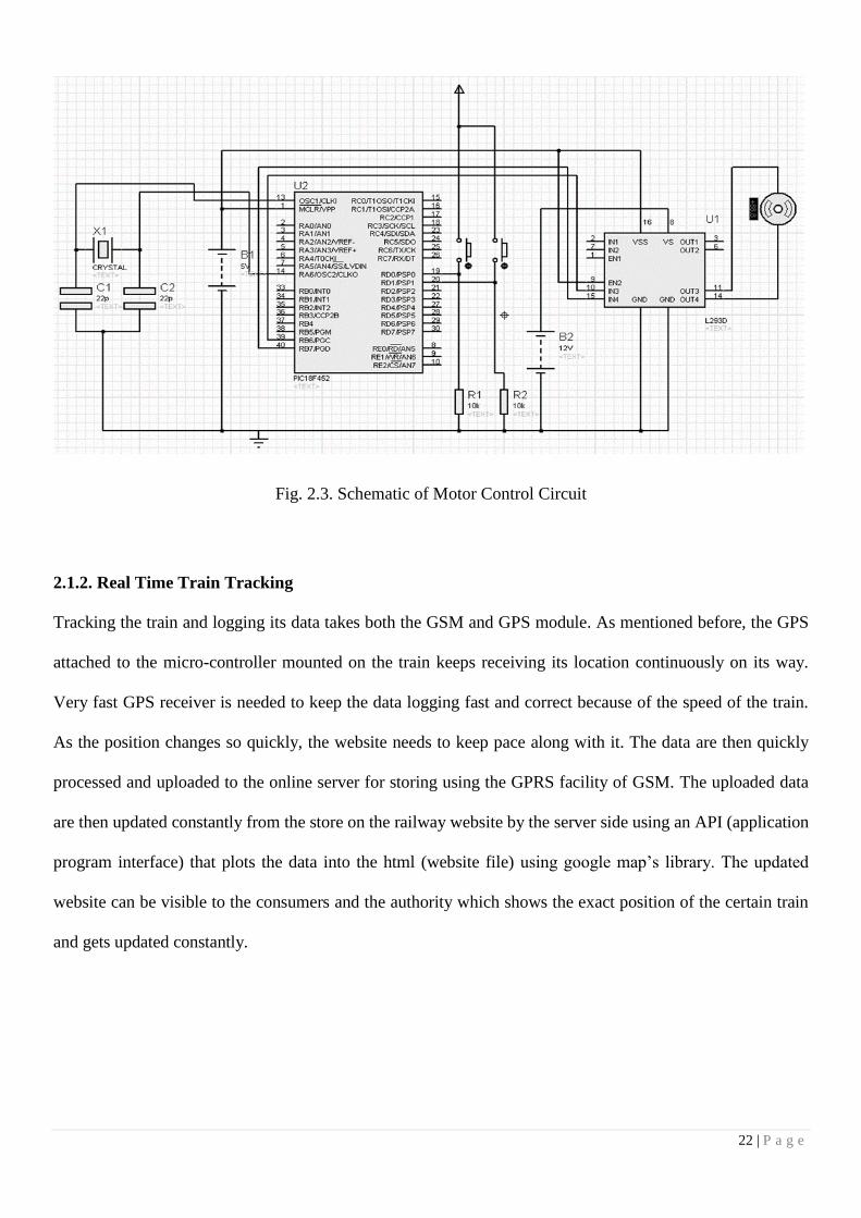
Fig. 2.3. Schematic of Motor Control Circuit
2.1.2. Real Time Train Tracking
Tracking the train and logging its data takes both the GSM and GPS module. As mentioned before, the GPS
attached to the micro-controller mounted on the train keeps receiving its location continuously on its way.
Very fast GPS receiver is needed to keep the data logging fast and correct because of the speed of the train.
As the position changes so quickly, the website needs to keep pace along with it. The data are then quickly
processed and uploaded to the online server for storing using the GPRS facility of GSM. The uploaded data
are then updated constantly from the store on the railway website by the server side using an API (application
program interface) that plots the data into the html (website file) using google map’s library. The updated
website can be visible to the consumers and the authority which shows the exact position of the certain train
and gets updated constantly.

23 | P a g e
Fig. 2.4. Block Diagram of Real Time Tracking
2.1.3. Line Security
Fig. 2.5. Concept Diagram of Railway Line Security

24 | P a g e
Whether a rail track is functional this can be found out by the correct measure of the distance between the
parallel lines. In order to measure that correctly, modern sensors are being used. What causes the line
malfunction is the extreme heat and weight caused by the friction of massive weighted trains. The line tends
to get flatter from both sides. This displacement causes the change in the distance between the lines, which
results in accidents. The distance between the lines could be measured by modern light technologies like
lasers, which is used in counting the time of travelling of the light, which is later used to count the distance
by further calculations. But these technologies are way expensive to implement. So this research keeps the
same method, but with different technology. Two sets of identical IR series is used. Especially the distances
between the IR couples remain equal. Using this, a perfectly parallel rail line will always give the similar sets
of results for both the sets. A difference in the set of result implies that there is something not right with the
line at that place, which could be reported by sending the location when the flaw is detected. The readings
could be made more accurate by positioning the IR couples in a style, after which the IR receiver will only
detect the obstacle at a certain distance or will detect nothing.
2.2. Components
This section lists the hardware and software components which have been used in the project.
2.2.1. Hardware
This part describes the hardware components that were used to complete this project. Most of it contains
electronics including micro-controllers and sensors to implement logic.
2.2.1.1. GPS
The Global Positioning System (GPS) is a space-based satellite navigation system that provides location and
time information in all weather conditions, anywhere on or near the Earth where there is an unobstructed line
25 | P a g e
of sight to four or more GPS satellites. It is freely accessible to anyone with a GPS receiver [16]. Within the
tracking unit, the recorded location data can be stored or it may be transmitted to a central location data base,
or internet-connected computer, using a cellular (GPRS or GSM), radio, or satellite modem embedded in the
unit at regular intervals of time.
Essentially, the GPS receiver compares the time a signal was transmitted by a satellite with the time it was
received [16]. The time difference tells the GPS receiver how far away the satellite is. Now, with distance
measurements from a few more satellites, the receiver can determine the user's position and display it on the
unit's electronic map.
Basic GPS measurements yield only a position, and neither speed nor direction. However, most GPS units
can automatically derive velocity and direction of movement from two or more position measurements. The
disadvantage of this principle is that changes in speed or direction can only be computed with a delay, and
that derived direction becomes inaccurate when the distance travelled between two position measurements
drops below or near the random error of position measurement. GPS units can use measurements of the
Doppler shift of the signals received to compute velocity accurately. More advanced navigation systems use
additional sensors like a compass or an inertial navigation system to complement GPS.
A GPS receiver must be locked on to the signal of at least three satellites to calculate a 2D position (latitude
and longitude) and track movement. With four or more satellites in view, the receiver can determine the
user's 3D position (latitude, longitude and altitude) [16]. Once the user's position has been determined, the
GPS unit can calculate other information such as speed, bearing, track, trip distance, distance to destination,
sunrise and sunset time and more. A GPS receiver calculates its position by precisely timing the signals sent
by GPS satellites high above the Earth. Each satellite continually transmits messages that include the time the
message was transmitted and satellite position at time of message transmission. In typical GPS operation,
four or more satellites must be visible to obtain an accurate result [17]. The solution of the navigation
equations gives the position of the receiver along with the difference between the time kept by the receiver's

26 | P a g e
on-board clock and the true time-of-day, thereby eliminating the need for a more precise and possibly
impractical receiver based clock.
2.2.1.2. GPS Receiver
Fig. 2.6. Venus638FLPx GPS Receiver
The particular model of GPS module is used namely Venus638FLPx built by Sparkfun Electronics, USA
[18]. The module gives an easy access to get NMEA data out of it. Its TX pin continuously sends data out of
it. It’s based on the Venus638FLPx, the successor to the Venus634LPx. The Venus638FLPx outputs standard
NMEA-0183 or SkyTraq Binary sentences at a default rate of 9600bps (adjustable to 115200bps), with
update rates up to 20Hz. This board includes a SMA connector to attach an external antenna, headers for
3.3V serial data, NAV (lock) indication, Pulse-Per-Second output, and external Flash support. This board
requires a regulated 3.3V supply to operate; at full power the board uses up to 90mA, at reduced power it
requires up to 60mA. Connection of this pin with the RX pin of the computer will send the data to the
computer serially [18]. The device has to be powered up with 3.3 volt and needs being grounded.
27 | P a g e
The specification of the device is that it cannot work without an antenna. For connecting it with an antenna,
built in SMA female connector is attached to it. Any Antenna with a male SMA connector attached could be
connected to it but a snag of this device is that it does not power up the antenna until external power is
supplied as per the antenna’s requirement to its Vbat pin. Powering that up, makes the device work smoothly.
2.2.1.3. GSM
GSM is a communication standard developed by the European Telecommunications Standards Institute
(ETSI) to describe protocols for second generation (2G) digital cellular networks used by mobile phones.
This system is popular all over the world now for mobile communication.
2G networks developed as a replacement for first generation (1G) analog cellular networks, and the GSM
standard originally described a digital, circuit-switched network optimized for full duplex voice telephony.
This expanded over time to include data communications, first by circuit-switched transport, then by packet
data transport via GPRS (General Packet Radio Services).
One of the famous feature of GSM technology is SMS or Short Messaging Service. Using which feature
written data could be sent from the sender to the receiver. This service is used in this research to transfer
command in the form of text from one section of the system to other frequently. With the regular service
quality, SMS is a very fast technique to send data.
2.2.1.4. GPRS
GPRS is a packet oriented mobile data service on the 2G cellular communication system's global system for
GSM. It can do multiple functions using a device such as requesting an http webpage. Using this operation,
uploading and downloading data is possible, as the http request does both uploading and downloading while
executing its function. In this research GPRS with cellular module is used to upload our current location data

28 | P a g e
from the train to the railway server, which later updates the railway website for the real time tracking of the
train.
2.2.1.5. GSM/GPRS Module
From different modules available in the market, GSM/GPRS module (version 1.2) from elecfreaks is being
chosen for the research [19]. The device is easy to interface with the computer. The device uses the SIM900
GSM/GPRS module from SIMCom Technology Group Ltd [20]. The module uses AT commands to execute
user desired function. The device was used to send SMS carrying signal from one sub cell to other. The
GPRS network was used to upload the location data to server. The device works being powered by the on
board computer, but to function properly it requires external power with a current rating as high as 2A [19].
The network led on the module shows the stability of the network, which must be noticed carefully. Until the
network gets stable, the module fails to work properly.
GPRS Shield - EFCom is an ultra-compact and reliable wireless module. This GPRS Shield is compatible
with all boards which have the same form factor (and pinout) as a standard Arduino Board. EFCom is based
on SIM900 4 Frequency GPRS module, which delivers GSM/GPRS 850/900/1800/1900MHz performance
for voice, SMS, Data, and Fax in a small form factor and with low power consumption. SIM900 is a
complete Quad-band GSM/GPRS module in a SMT type and designed with a very powerful single-chip
processor integrating AMR926EJ-S core, allowing you to benefit from small dimensions and cost-effective
solutions.
29 | P a g e
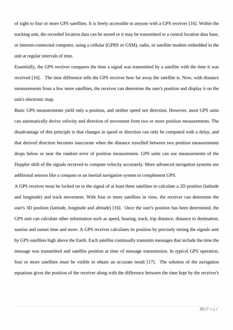
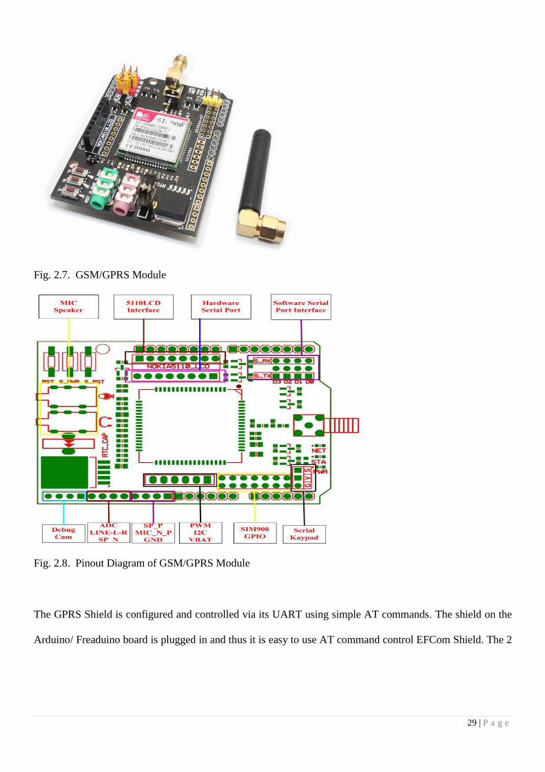
Fig. 2.7. GSM/GPRS Module
Fig. 2.8. Pinout Diagram of GSM/GPRS Module
The GPRS Shield is configured and controlled via its UART using simple AT commands. The shield on the
Arduino/ Freaduino board is plugged in and thus it is easy to use AT command control EFCom Shield. The 2

30 | P a g e
jumper block to connect the SIM900 URAT post to any pins within D0-D3 (for Hardware/Software serial
port) can also be used. There is a switch on board , which can be used to select the connection of the UART
port or Debug port and even be set on Arduino, but by the switch and jumper block, the SIM900 can be
connect to PC via FT233RL [21].
2.2.1.6. Micro-Controller
This project is based on a few micro-controllers in different sub-systems of the whole system. These
controllers handle the functions to be executed locally in the sub-systems for the easy interfacing capability
with the other components that was being used and versatility. The one being suitable for this project is
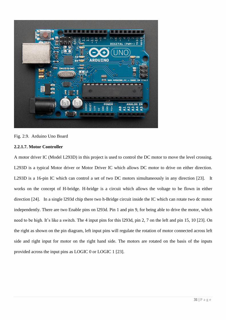
Arduino Uno Rev. 3 made by Arduino organization.
The Arduino Uno is a microcontroller board based on the ATmega328 by Atmel Corporation. It has 14
digital input/output pins (of which 6 can be used as PWM outputs), 6 analog inputs, a 16 MHz ceramic
resonator, a USB connection, a power jack, an ICSP header, and a reset button. It contains everything needed
to support the microcontroller; simply connect it to a computer with a USB cable or power it with a AC-to-
DC adapter or battery to get started. The Arduino Uno can be powered via the USB connection or with an
external power supply. The power source is selected automatically. External (non-USB) power can come
either from an AC-to-DC adapter (wall-wart) or battery. The adapter can be connected by plugging a 2.1mm
center-positive plug into the board's power jack. Leads from a battery can be inserted in the Gnd and Vin pin
headers of the POWER connector. The board can operate on an external supply of 6 to 20 volts. If supplied
with less than 7V, however, the 5V pin may supply less than five volts and the board may be unstable. If
using more than 12V, the voltage regulator may overheat and damage the board. The recommended range is
7 to 12 volts. The ATmega328 has 32 KB (with 0.5 KB used for the boot loader). It also has 2 KB of SRAM
and 1 KB of EEPROM, which can be read and written with the EEPROM library [22].
31 | P a g e
Fig. 2.9. Arduino Uno Board
2.2.1.7. Motor Controller
A motor driver IC (Model L293D) in this project is used to control the DC motor to move the level crossing.
L293D is a typical Motor driver or Motor Driver IC which allows DC motor to drive on either direction.
L293D is a 16-pin IC which can control a set of two DC motors simultaneously in any direction [23]. It
works on the concept of H-bridge. H-bridge is a circuit which allows the voltage to be flown in either
direction [24]. In a single l293d chip there two h-Bridge circuit inside the IC which can rotate two dc motor
independently. There are two Enable pins on l293d. Pin 1 and pin 9, for being able to drive the motor, which
need to be high. It’s like a switch. The 4 input pins for this l293d, pin 2, 7 on the left and pin 15, 10 [23]. On
the right as shown on the pin diagram, left input pins will regulate the rotation of motor connected across left
side and right input for motor on the right hand side. The motors are rotated on the basis of the inputs
provided across the input pins as LOGIC 0 or LOGIC 1 [23].

32 | P a g e
VCC is the voltage that it needs for its own internal operation 5v; L293D will not use this voltage for driving
the motor. For driving the motors it has a separate provision to provide motor supply VSS (V supply). L293d
will use this to drive the motor. The maximum voltage for VSS motor supply is 36V. It can supply a max
current of 600mA per channel [23].
Fig. 2.10. Motor Driver IC (Model No. L293D)
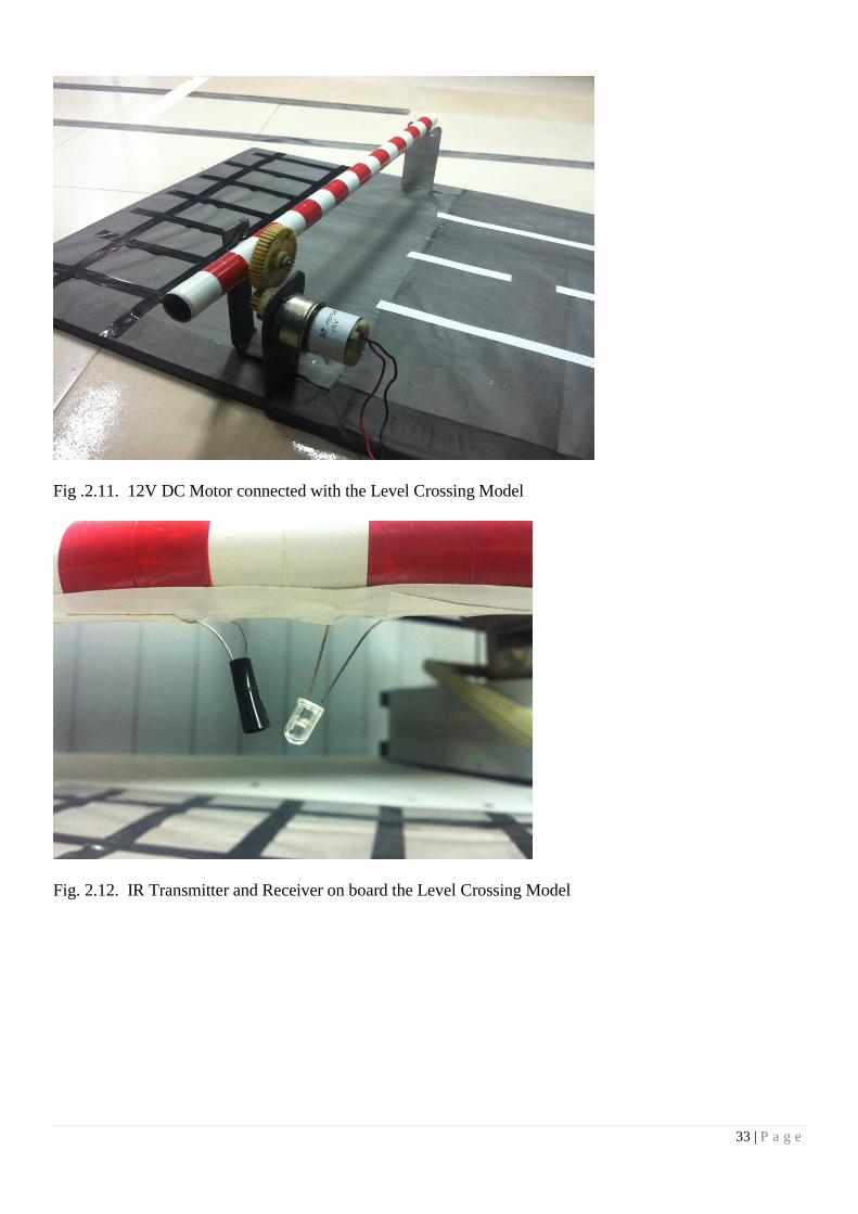
2.2.1.8. DC Motor
A 12V DC motor is being chosen to control the position of the level crossing. It is joined with the existing
man handled liver to control it by the micro-controller through the motor driver. Fig. 2.11 contains a picture
of the 12V DC motor that is used in this work.
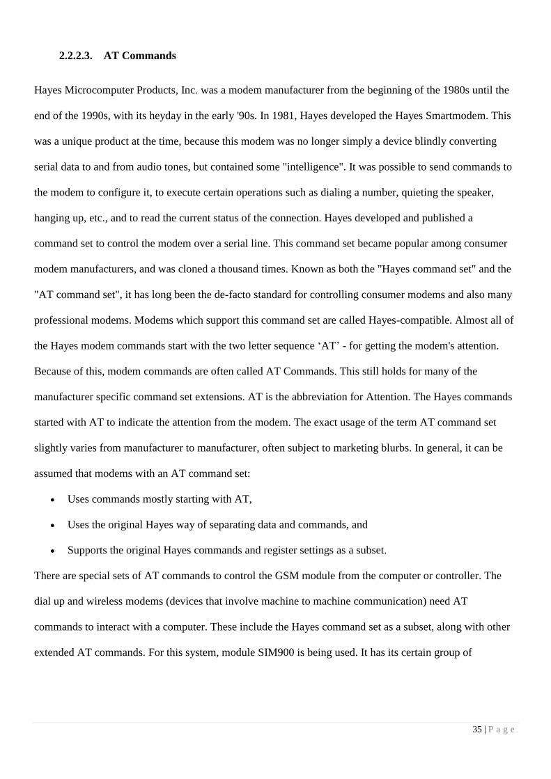
2.2.1.9. IR Transmitters and Receivers
IR transmitters and receivers are used for this project to detect any threat to rail line. It is mainly used for line
security. It is also used to detect if there is any car under the level crossing and the final situation of the level
crossing which is sent to the train from the crossing. Fig. 2.12 contains picture of the IR transmitter and
receiver on board the level crossing model.
33 | P a g e
Fig .2.11. 12V DC Motor connected with the Level Crossing Model
Fig. 2.12. IR Transmitter and Receiver on board the Level Crossing Model

34 | P a g e
2.2.2. Software
Given the complexity of this project, it requires a host of software’s that fulfill different requirements. The
variety of software controls different parts of the hardware and carry out different functions. Fulfilling the
different requirements and functions lead to make the integrated hardware.
2.2.2.1. Arduino IDE
One of the main software that is used in this project heavily is the Arduino IDE (Integrated Development
Environment) as Arduino microcontrollers are used in this project. Arduino IDE is written in Java and is a
cross-platform application. It is designed to help programmers to configure the Arduino microcontrollers to
their preference. Arduino programs are written in C or C++ but require two functions, setup() and loop(), to
make a runnable cyclic executive program. The setup() function initializes all the settings and runs once at
the start of the program. The loop() function executes the microcontrollers main job and is called repeatedly
until the board powers off.
2.2.2.2. GSM Library
The GSM Shield library contains the source and header files for the necessary functions required to
exchange texts through GSM and uploading it to a website where the movements of the trains can be
tracked. Hence, this needs to be imported into the Arduino library. An Arduino Uno board can have code of
up to 32bytes burnt into it. Including the libraries helps us write a compact code which otherwise would
have been very huge and disorganized, given the huge number of functions involved. The library contains
most of the functions of the SIM900 module we have used in the ‘SIM900’ source file.
35 | P a g e
2.2.2.3. AT Commands
Hayes Microcomputer Products, Inc. was a modem manufacturer from the beginning of the 1980s until the
end of the 1990s, with its heyday in the early '90s. In 1981, Hayes developed the Hayes Smartmodem. This
was a unique product at the time, because this modem was no longer simply a device blindly converting
serial data to and from audio tones, but contained some "intelligence". It was possible to send commands to
the modem to configure it, to execute certain operations such as dialing a number, quieting the speaker,
hanging up, etc., and to read the current status of the connection. Hayes developed and published a
command set to control the modem over a serial line. This command set became popular among consumer
modem manufacturers, and was cloned a thousand times. Known as both the "Hayes command set" and the
"AT command set", it has long been the de-facto standard for controlling consumer modems and also many
professional modems. Modems which support this command set are called Hayes-compatible. Almost all of
the Hayes modem commands start with the two letter sequence ‘AT’ - for getting the modem's attention.
Because of this, modem commands are often called AT Commands. This still holds for many of the
manufacturer specific command set extensions. AT is the abbreviation for Attention. The Hayes commands
started with AT to indicate the attention from the modem. The exact usage of the term AT command set
slightly varies from manufacturer to manufacturer, often subject to marketing blurbs. In general, it can be
assumed that modems with an AT command set:
Uses commands mostly starting with AT,
Uses the original Hayes way of separating data and commands, and
Supports the original Hayes commands and register settings as a subset.
There are special sets of AT commands to control the GSM module from the computer or controller. The
dial up and wireless modems (devices that involve machine to machine communication) need AT
commands to interact with a computer. These include the Hayes command set as a subset, along with other
extended AT commands. For this system, module SIM900 is being used. It has its certain group of

36 | P a g e
commands. As sending SMS between different cells of the system is a prime need, the SMS commands are
used.The GPS data is being uploaded on a web server which continuously updates a website and allows the
users and the authority to track the specific train they want to. The GPS data is forwarded from the GPS
receiver on to the web server after which the httpGET() and httpPOST() functions, within the inetGSM
source file, retrieves this information from the server and update it continuously onto the website. Here
again the GSM Shield library is required. The AT commands in the functions mentioned above use the
HTTP commands [25].
TABLE 2.1 AT Commands for GSM
TABLE 2.2 AT Commands for GPRS
Command Response Description
AT+SAPBR OK Configures GPRS profile
AT+HTTPINIT OK Initializes HTTP service
AT+HTTPPARA OK Configures HTTP parameters
AT+HTTPACTION=0 OK Sets HTTP Method Action, GET in this chase.
AT+HTTPREAD Reads HTTP data
AT+HTTPTERM OK Closes the opened HTTP session.
Command Response Description
AT+CMGF= OK Specifies the input and output format of the short messages. 0
for PDU mode and 1 for text mode.
AT+CMGS Sends a message.
AT+CMGR=* Reads a message. * is the number of the message.

37 | P a g e
2.2.2.4. Google Maps API
The website, where we can monitor the train’s movements, is written in HTML5 and JavaScript. Google
Maps is used to show the current location of the train. Using Google Maps API v3 (Version 3) allows
Google Maps to be embedded onto any third-party websites, on to which site specific data can be overlaid
[26]. An application programming interface (API) is a set of routines, protocols, and tools for building
software applications. An API expresses a software component in terms of its operations, inputs, outputs,
and underlying types. Google Maps API belongs to a set of APIs developed by Google which allow
communication with Google Services and their integration to other services. Google Maps is chosen instead
of Bing or Apple Maps as on the web all of them have more or less the same features with Google and Bing
being much more polished. On the phone however, Google Maps edges both of them out as it has more
features. Given that the number of users of smart phones and tablets are increasing more day by day and the
vast majority of them are Android users, using Google Maps was necessary [27].
2.2.2.5. Proteus
Proteus VSM (Virtual System Modeling) is a software for microprocessor simulation and schematic
capture, has been used to simulate the program on animated components and microprocessor models to test
our designs before the actual hardware is constructed [28]. This is possible because you can interact with the
design using on screen indicators such as LED and LCD displays and actuators such as switches and
buttons. The simulation takes place in real time. Proteus VSM also provides extensive debugging facilities
including breakpoints, single stepping and variable display for both assembly code and high level language
source.
Proteus VSM uses Labcenter Electronics proven Schematic Capture software to provide the environment for
design entry and development. Proteus capture is a long established product and combines ease of use with

38 | P a g e
powerful editing tools. It is capable of supporting schematic capture for both simulation and PCB design.
Designs entered in to Proteus VSM for testing can be net listed for PCB layout either with our own PCB
Design products or with third party PCB layout tools. The Proteus schematic capture module also provides a
very high degree of control over the drawing appearance, in terms of line widths, fill styles, fonts, etc. These
capabilities are used to the full in providing the graphics necessary for circuit animation. At the heart of
Proteus VSM is ProSPICE. This is an established product that combines uses a SPICE3f5 analogue
simulator kernel with a fast event-driven digital simulator to provide seamless mixed-mode simulation. The
use of a SPICE kernel lets you utilize any of the numerous manufacturer-supplied SPICE models, now
available and around 6000 of these, are included with the package. Proteus VSM includes a number of
virtual instruments including an Oscilloscope, Logic Analyzer, Function Generator, Pattern Generator,
Counter Timer and Virtual Terminal as well as simple voltmeters and ammeters.
2.2.2.6. SSCom
SSCOM is a serial monitor based software which analyses the AT commands being sent and received from
a device as well as providing a look into the underlying process that takes place during those interchanges,
which gave us a proper understanding of what is happening inside in response to our input commands.
2.2.2.7. NMEA
GPS receiver receives data in a special format or sentence known as NMEA sentence. This sentence
includes all the necessary data to determine the location accurately. This data includes the complete PVT
(position, velocity, time) solution computed by the GPS receiver. NMEA is the short form of National
Marine Electronics Association, it is a self-sustaining organization committed to enhancing the technology
and safety of electronics used in marine applications worldwide. NMEA works sending line of data called a
39 | P a g e
sentence which is totally self-contained and independent from other sentences. There are standard sentences
for each of the device category. All of the standard sentences have a two letter prefix that defines the device
that uses that sentence type. For instance for GPS receivers this prefix is “GP”, which is followed by a three
letter sequence that defines the sentence contents. There are several NMEA standards and two of them that
are widely used namely NMEA 0183 and NMEA 2000.
The idea of NMEA is to send a line of data called a sentence that is totally self-contained and independent
from other sentences. There are standard sentences for each device category and there is also the ability to
define proprietary sentences for use by the individual company. All of the standard sentences have a two
letter prefix that defines the device that uses that sentence type (For GPS receivers the prefix is GP.) which
is followed by a three letter sequence that defines the sentence contents. In addition NMEA permits
hardware manufactures to define their own proprietary sentences for whatever purpose they see fit.
Each sentence begins with a '$' and ends with a carriage return/line feed sequence and can be no longer than
80 characters of visible text (plus the line terminators). The data is contained within this single line with
data items separated by commas. The data itself is just ASCII text and may extend over multiple sentences
in certain specialized instances but is normally fully contained in one variable length sentence. The data
may vary in the amount of precision contained in the message. For example time might be indicated to
decimal parts of a second or location may be show with 3 or even 4 digits after the decimal point. Programs
that read the data should only use the commas to determine the field boundaries and not depend on column
positions. There is a provision for a checksum at the end of each sentence which may or may not be checked
by the unit that reads the data. The checksum field consists of a '*' and two hex digits representing an 8 bit
exclusive OR of all characters between, but not including, the '$' and '*'. A checksum is required on some
sentences.
There have been several changes to the standard but for GPS use the only ones that are likely to be
encountered are 1.5 and 2.0 through 2.3. These just specify some different sentence configurations which
40 | P a g e
may be peculiar to the needs of a particular device thus the GPS may need to be changed to match the
devices being interfaced to. Some GPS's provide the ability configure a custom set the sentences while other
may offer a set of fixed choices. Many GPS receivers simply output a fixed set of sentences that cannot be
changed by the user.
There are a few standards or versions of NMEA sentences. Among which NMEA 0183 and NMEA 2000
are the most popular. Different receivers follow different versions of NMEA sentences. Our receiver uses
NMEA 0183. NMEA 0183 interface Standard defines electrical signal requirements, data transmission,
time, and specific sentence formats for different baud rate of serial data bus; each bus may have only one
talker but many listeners. This standard supports one-way serial data transmission from a single talker to
one or more listeners. Whereas NMEA 2000 standard is multi-master and self-configuring, and there is no
central network controller. Equipment designed to this standard will have the ability to share data, including
commands and status with other compatible equipment over a single channel. Undoubtedly NMEA 2000 is
50 times faster than 0183 but it does not support high bandwidth applications. NMEA 2000 is quite new
which are still being implemented on the contrary NMEA 0183 is well known as it has been used for a long
time by replacing the earlier NMEA 0180 and 0182 standards on the top of that most systems are familiar to
this standard, so we ended up on using this standard for our GPS system, positioning the train.
NMEA consists of sentences, the first word of which, called a data type, defines the interpretation of the rest
of the sentence. Each Data type would have its own unique interpretation and is defined in the NMEA
standard. The GGA sentence shows an example that provides essential fix data. Other sentences may repeat
some of the same information but will also supply new data. Whatever device or program that reads the data
can watch for the data sentence that it is interested in and simply ignore other sentences that is doesn't care
about. In the NMEA standard there are no commands to indicate that the GPS should do something
different. Instead each receiver just sends all of the data and expects much of it to be ignored. Some
receivers have commands inside the unit that can select a subset of all the sentences or, in some cases, even

41 | P a g e
the individual sentences to send. There is no way to indicate anything back to the unit as to whether the
sentence is being read correctly or to request a re-send of some data you didn't get. Instead the receiving unit
just checks the checksum and ignores the data if the checksum is bad figuring the data will be sent again
sometime later.
There are many sentences in the NMEA standard for all kinds of devices that may be used in a Marine
environment. Some of the ones that have applicability to GPS receivers are listed below: (all message start
with GP.)
AAM - Waypoint Arrival Alarm
ALM - Almanac data
APA - Auto Pilot A sentence
APB - Auto Pilot B sentence
BOD - Bearing Origin to Destination
BWC - Bearing using Great Circle route
DTM - Datum being used.
GGA - Fix information
GLL - Lat/Lon data
GRS - GPS Range Residuals
GSA - Overall Satellite data
GST - GPS Pseudo range Noise Statistics
GSV - Detailed Satellite data
MSK - send control for a beacon receiver
MSS - Beacon receiver status information.
RMA - recommended Loran data
RMB - recommended navigation data for GPS
42 | P a g e
RMC - recommended minimum data for GPS
RTE - route message
TRF - Transit Fix Data
STN - Multiple Data ID
VBW - dual Ground / Water Speed
VTG - Vector track an Speed over the Ground
WCV - Waypoint closure velocity (Velocity Made Good)
WPL - Waypoint Location information
XTC - cross track error
XTE - measured cross track error
ZTG - Zulu (UTC) time and time to go (to destination)
ZDA - Date and Time
The most important NMEA sentences include the GGA which provides the current Fix data, the RMC
which provides the minimum GPS sentences information, and the GSA which provides the Satellite status
data. Regular GGA data are like the example shown below. Each of its part derives special meaning. The
basic partitions of the GGA sentence are described item by item below. One can get a clear idea about the
meaning of the sentence part by part from the original sentence.
GGA - essential fix data which provide 3D location and accuracy data.
$GPGGA,123519,4807.038,N,01131.000,E,1,08,0.9,545.4,M,46.9,M,,*47
Where:
GGA Global Positioning System Fix Data
123519 Fix taken at 12:35:19 UTC
4807.038,N Latitude 48 deg 07.038' N
01131.000,E Longitude 11 deg 31.000' E
43 | P a g e
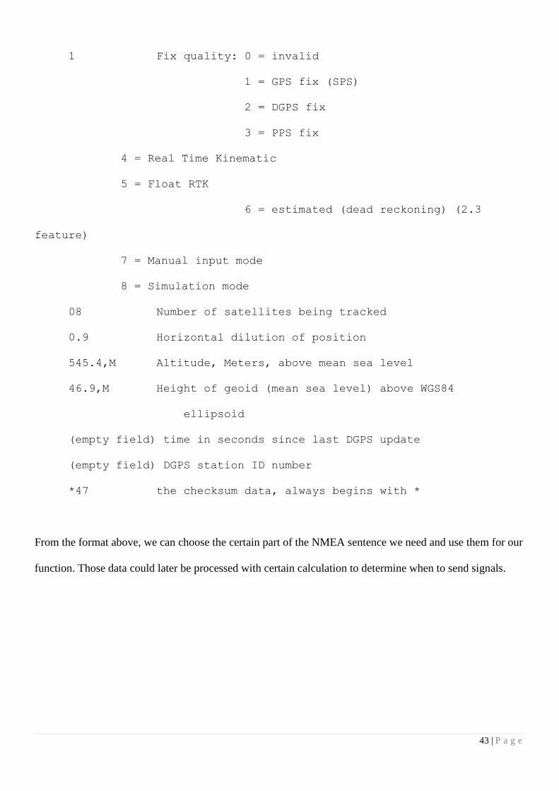
1 Fix quality: 0 = invalid
1 = GPS fix (SPS)
2 = DGPS fix
3 = PPS fix
4 = Real Time Kinematic
5 = Float RTK
6 = estimated (dead reckoning) (2.3
feature)
7 = Manual input mode
8 = Simulation mode
08 Number of satellites being tracked
0.9 Horizontal dilution of position
545.4,M Altitude, Meters, above mean sea level
46.9,M Height of geoid (mean sea level) above WGS84
ellipsoid
(empty field) time in seconds since last DGPS update
(empty field) DGPS station ID number
*47 the checksum data, always begins with *
From the format above, we can choose the certain part of the NMEA sentence we need and use them for our
function. Those data could later be processed with certain calculation to determine when to send signals.
44 | P a g e
2.2.3. The Integrated System
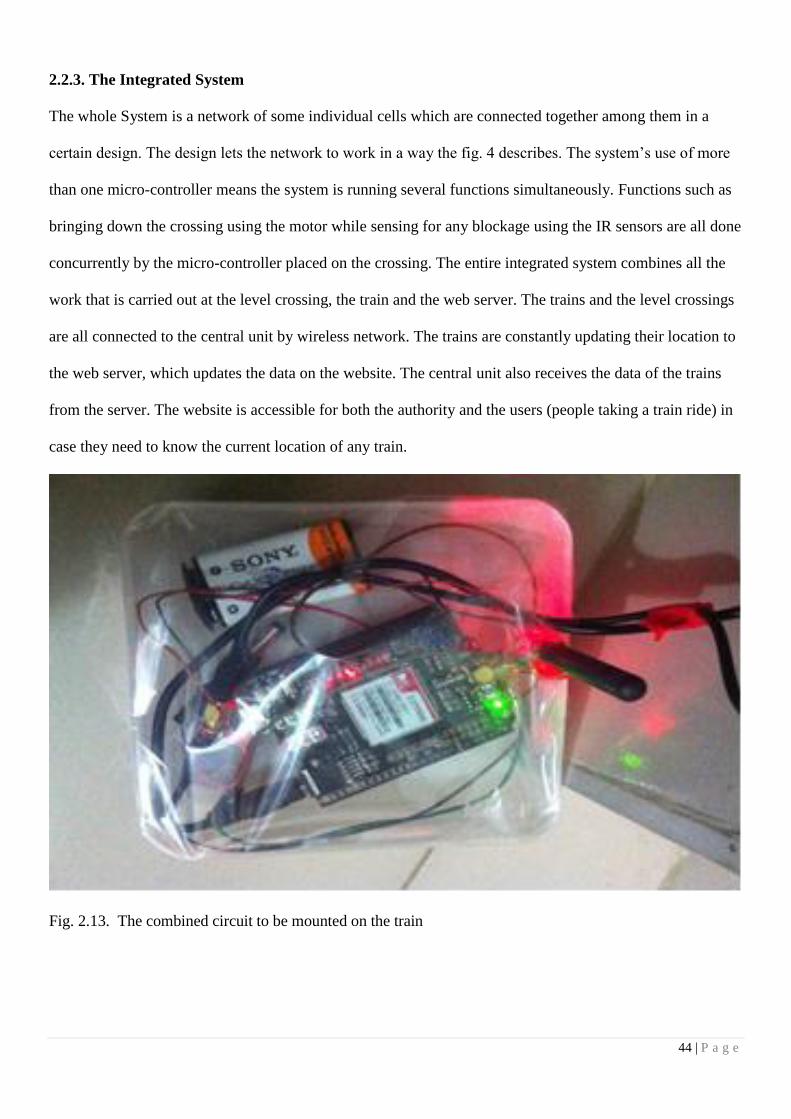
The whole System is a network of some individual cells which are connected together among them in a
certain design. The design lets the network to work in a way the fig. 4 describes. The system’s use of more
than one micro-controller means the system is running several functions simultaneously. Functions such as
bringing down the crossing using the motor while sensing for any blockage using the IR sensors are all done
concurrently by the micro-controller placed on the crossing. The entire integrated system combines all the
work that is carried out at the level crossing, the train and the web server. The trains and the level crossings
are all connected to the central unit by wireless network. The trains are constantly updating their location to
the web server, which updates the data on the website. The central unit also receives the data of the trains
from the server. The website is accessible for both the authority and the users (people taking a train ride) in
case they need to know the current location of any train.
Fig. 2.13. The combined circuit to be mounted on the train

45 | P a g e
Chapter 3: Result Analysis
This first and most important aspect of this system is that by using it, the chances of accidents taking place at
the railway crossings are greatly reduced. Hence, the results of this system are calculated with precision
while also taking into factors that may change the outcome, such as the train of the speed.
Fig. 3.1. The Integrated System
3.1. Output
The outputs of this system, after all the work is done, will be a level crossing which is self-sustaining as long
as it is connected to a power supply, a train tracking system that continuously uploads GPS data on to the
web server so that the users of the system can monitor the movements of the train through the website and a
line security that checks for faults and defects on the line which may cause derailments.
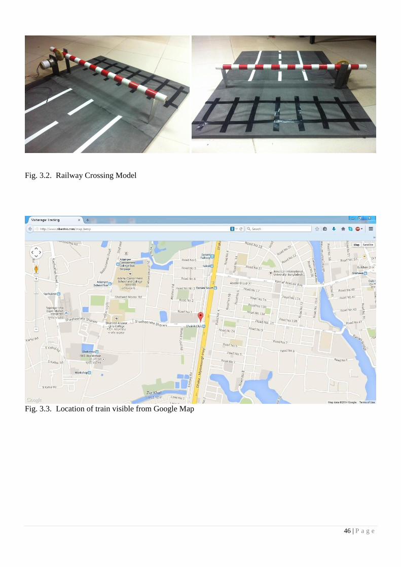
46 | P a g e
Fig. 3.2. Railway Crossing Model
Fig. 3.3. Location of train visible from Google Map
47 | P a g e
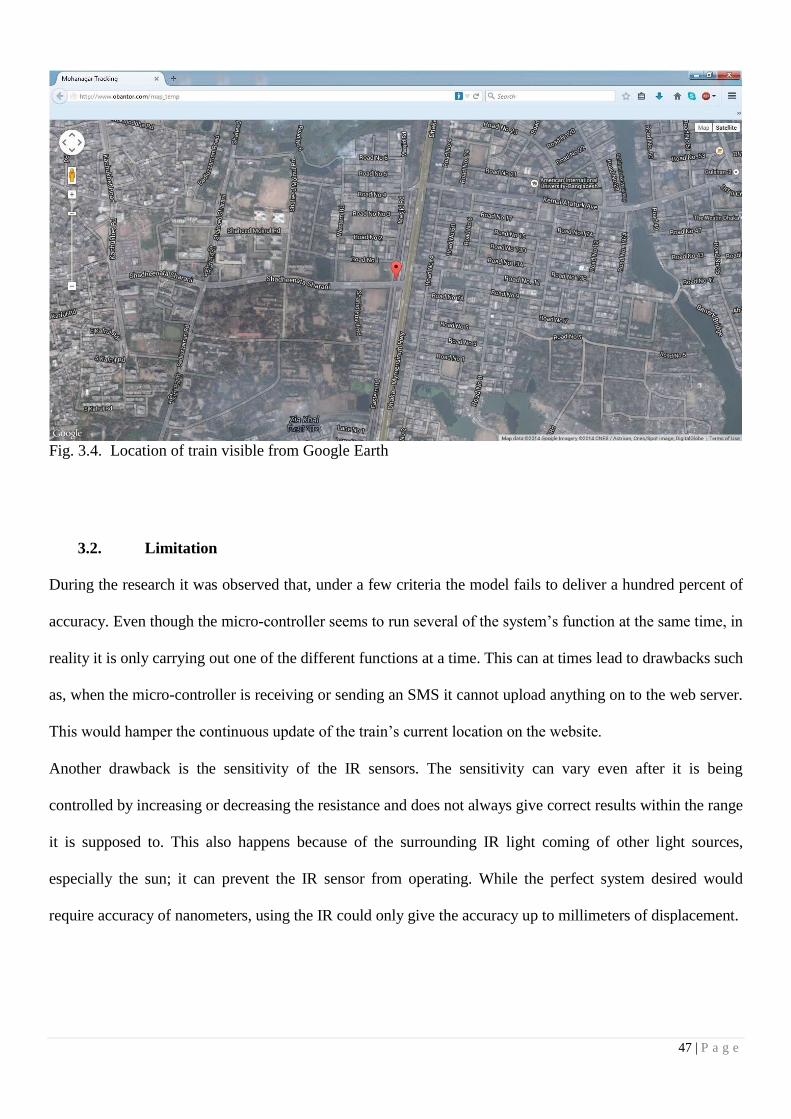
Fig. 3.4. Location of train visible from Google Earth
3.2. Limitation
During the research it was observed that, under a few criteria the model fails to deliver a hundred percent of
accuracy. Even though the micro-controller seems to run several of the system’s function at the same time, in
reality it is only carrying out one of the different functions at a time. This can at times lead to drawbacks such
as, when the micro-controller is receiving or sending an SMS it cannot upload anything on to the web server.
This would hamper the continuous update of the train’s current location on the website.
Another drawback is the sensitivity of the IR sensors. The sensitivity can vary even after it is being
controlled by increasing or decreasing the resistance and does not always give correct results within the range
it is supposed to. This also happens because of the surrounding IR light coming of other light sources,
especially the sun; it can prevent the IR sensor from operating. While the perfect system desired would
require accuracy of nanometers, using the IR could only give the accuracy up to millimeters of displacement.

48 | P a g e
It is also observed that the GPS has problems connecting with the network when the weather conditions are
very cloudy. Either, the time it takes to connect to the network is longer than usual or, in some cases it could
not connect to the network at all.
3.3. Comparison
The existing railway system within Bangladesh is really outdated with its use of technology like semaphore
and color-light signals, fixed and moving block signaling and a telecommunication network used to exchange
messages between one station and the next which means there is no centralized system.
In comparison to the current system, the automated system proposed would be far more sufficient. It would
be able to delocalize data collected from every station and would allow a team to oversee the entire
operations at the main control unit as well as make the location of the trains available to all users visiting the
website. At the crossing, the reaction time between receiving messages and acting upon it is greatly
decreased as the human element is removed. The crossing will go down within 7-8 seconds, given that it does
not face any interference. This makes the proposed system far more efficient and self-sustaining than the
current one.
49 | P a g e
Chapter 4: Conclusion
4.1 Summary
This paper aims to an automated railway system that collaborates three smart subsystems. Initially an
unmanned automated gate control at the line crossing, then detection of the surface defects at of the railway
tracks and finally a centralized railway tracking facility at any location using GPS technology. From the
above discussion and information of this system, it is clear that the system is quite reliable, effective and
economical for a developing country. As the system is completely automated, it avoids manual errors and
thus provides ultimate safety. By this mechanism, presence of a gatekeeper is not necessary and automatic
operation of the gate through the motor action is achieved. This reduces the cost of human labors every year.
If there is any difficulty then train will stop at few distances from the level crossing which clearly ensures
safety by avoiding dreadful accidents that has been happening in recent years. Moreover, an automated
system helps to save a lot of time than that of a manual system. Due to the above stated reasons it could be
concluded that this design is not only helpful for improving the present railway system but it will also be a
fructiferous system for the benefit of mankind.
4.2 Discussion
After a train starts to leave a particular station the stationmaster delivers the message to the next gate and this
loop is conducted till the train reach its particular destination. The message is being passed with the help of
telecommunication services. The current systems in place at level crossings are manually controlled.
Constant telecommunication contact is maintained by those on the train and at the crossing to determine
when the bar has to go down. If due to some unforeseen reasons, the train is delayed, the gate remains closed
and increases traffic problems. Even if the personnel on the train warn those at crossing, therein lays the

50 | P a g e
problem of alerting all the other incoming trains. There is no centralized system to distribute information
throughout the entire network of trains and crossing in an efficient manner.
Many level crossings sprout up in an authorized way. This stands a challenge to guard them, the manual
system seeks a lot of human attention. Giving that amount of labor is quite an impossible task to do 24/7.
Whereas an automated system can function quite smoothly without any break.
A number of employs engulfs an unnecessary cost every year. BR employs around 34,168 people to cover
the demand. It is an obvious fact that automated system could smoothly remove the loss of money that is
spent over human wages.
By employing the automated railway system, less time is required to exchange messages between the trains,
crossings, and the main control system. This means the system can react to situations, possibly threatening,
faster and hence prevent it from taking place all together. Since the crossings in this system are unmanned,
human errors are avoided as well as costs of human labor are greatly reduced. The line checking, which is
missing in the current system, will look for any bents on the tracks, using IR sensors, which might cause
derailments.
The initial and primary motivation for creating this system still is to reduce the injuries caused and lives lost
due to accidents happening at level crossings. An automated system is more reliable, effective and efficient
than a manual one. The numerous advantages it brings are a testament of that.
4.3 Future Possibilities
The railway system in our country is quite a huge system with almost every part of it being controlled
manually. This is neither efficient nor accurate. The ones, that was develop into automated parts, even
without them there are other sectors which could be automated for day to day use. A major number of
accidents occur due to head on collisions or rear end collisions. Head on collision occurs when two trains
collide face to face with each other or train colliding on the same track from opposite ends. Rear end collision

51 | P a g e
is the other kind of collision when a train collides into the other train that is in front of it but moving in the
same direction. This happens due to signaling fault made by the humans. Due to the absence of a centralized
system and depending on the telecommunication system a communication gap remains among the station
masters resulting in these type of accidents. Therefore line switching could be added to this automated
system to avoid the collision of two trains by preventing them from running on same track. Furthermore train
scheduling could be developed into a digital system. As all the trains could be continuously tracked using this
proposed system, a railway network could be implemented using all the current train locations with custom
maps built only for the railway. Therefore, all the railway decisions could be auto generated without the any
human labor. An even smarter system joined with online and mobile customer service could totally build a
whole self-running railway network, which will be executing every rail operation in the country.
52 | P a g e
REFERENCES
[1] Ministry of Railway [Online] Available:
http://www.mof.gov.bd/en/budget/14_15/gender_budget/en/26_51_Railway_English.pdf
[2] Bangladesh Railway [Online] Available: http://www.railway.gov.bd/br_short.asp
[3] Analysis of Problems [Online] Available:
http://railway.portal.gov.bd/sites/default/files/files/railway.portal.gov.bd/page/672798ac_ee99_4686_9e
63_d69ef8e9a281/3.%20Analysis%20of%20Problems.pdf
[4] Md. Rakibul Hasan. (2009, August 10). “Problems and Prospects of a railway: A case study in
Bangladesh Railway”. Journal of Service Marketing. Volume-4, pp. 124-136
[5] [Online] Available: http://www.albd.org/index.php/en/resources/special-reports/939-five-year-
working-plan-of-al-government-for-developing-the-railway-sector
[6] Shahnaz Parveen, “2010 sees 590 train accidents”, The Daily Star, December 10, 2010.
[7] Railway Services, “Bangladesh railway train schedule and stations” [Online] Available:
http://www.mediabangladesh.net/companies/railway.php
[8] “ Train Crash: Body formed to investigate”, The Bangladesh today, October 23, 2014. [Online]
Available: http://thebangladeshtoday.com/latest-updates/2014/04/train-crash-body-formed-to-
investigate/
[9] “Train derailment in Bangladesh kills 4, opposition activists blamed”, UPI, December 4, 2013. [Online]
Available: http://www.upi.com/Top_News/World-News/2013/12/04/Train-derailment-in-Bangladesh-kills-
4-opposition-activists-blamed/UPI-29811386158071/
[10] Philip Caulfield, “Grisly head-to-head train crash in Bangladesh kills at least 19, injures hundreds”,
Daily News, December 08, 2010.
[11] “Running train hits waiting Express 2 killed, 40 injured”, The News Nation, October 23, 2014. [Online]
Available: http://thedailynewnation.com/news/9492/running-train-hits-waiting-express-2-killed-40-
injured.html
[12] Andy Doherty, Steve Clark, Robert Care and Mark Dembosky. (2005, June 23). “Why Rails Crack?”, The
Ingenia Magzine. [On-line] pp. 23-27. Available:
http://www.ingenia.org.uk/ingenia/issues/issue23/Doherty.pdf
[13] ] Kiruthiga, Dhivya.M, Yugapriya.R. (2007). Wireless Communication System For Railway
Signal Automation At Unmanned Level. International Journal of Innovative Research in Science,
Engineering and Technology. Volume 3, Special Issue 1.
[14] Subrata Biswas, Rafiul Hoque Bhuiyan, Samiul Hoque, Robiul Hasan, Tanzila Nusrat Khan. (2013).
Pressure Sensed Fast Response Anti-Collision System for Automated Railway Gate ControlAmerican
Journal of Engineering Research. Volume-02, Issue-11, pp-163-173.
53 | P a g e
[15] Kawshik Shikder. (2014, March). Intelligent System for Train Engine with Automatic Gate Controlling
using Wireless Technology in Bangladesh. International Journal of Science and Research. Volume 3, Issue 3.
[16] PROTOCOL, ALIS SERVER. "SPECIFICATIONS 1.00." (1994). [Online] Available:
http://www8.garmin.com/aboutGPS/
[17] The Global Positioning Cookie. [Online] Available: http://www.gpscookie.com/how-gps-works/
[18] [Online] Available: https://www.sparkfun.com/products/11058
[19] [Online] Available: http://www.elecfreaks.com/wiki/index.php?title=EFCom_GPRS/GSM_Shield
[20] Simcom. [Online] Available: http://wm.sim.com/producten.aspx?id=1019
[21] [Online] Available: elecfreaks.com/store/download/datasheet/wireless/EFcom_v1.2.pdf
[22] ARDUINO [Online] Available: http://arduino.cc/en/Main/arduinoBoardUno
[23] RON BOBOTICS [Online] Available: http://www.rakeshmondal.info/L293D-Motor-Driver
[24] [Online] Available: http://books.google.com.bd/books?id=E0_07GfXo2wC&pg=PA344&redir_esc=y
[25] SIMCom [Online] Available: http://www.simcom.ee/documents/gsm-
gprs/sim900/SIM900_AT%20Command%20Manual_V1.09.pdf
[26] Google Maps Embed API [Online] Available:
https://developers.google.com/maps/documentation/embed/guide
[27] [Online] Available:
http://www.pcworld.com/article/258328/google_maps_vs_bing_maps_a_showdown_of_satellite_images
.html
[28] [Online] Available: http://www.labcenter.com/products/vsm/vsm_overview.cfm