an automated rapid mapping solution based on orb … · an automated rapid mapping solution based...
TRANSCRIPT

An Automated Rapid Mapping Solution Based
on ORB SLAM 2 and Agisoft Photoscan API
Institute of Flight Guidance, TU Braunschweig, Germany
Slide 2
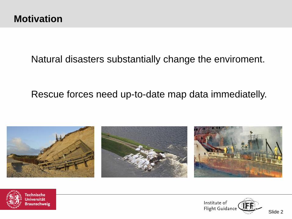
Motivation
Natural disasters substantially change the enviroment.
Rescue forces need up-to-date map data immediatelly.

Slide 3
Goal
Prototype mapping drone for disaster responce forces
Accurate aerial mapping
Results as fast as possible
Little training required
Slide 4
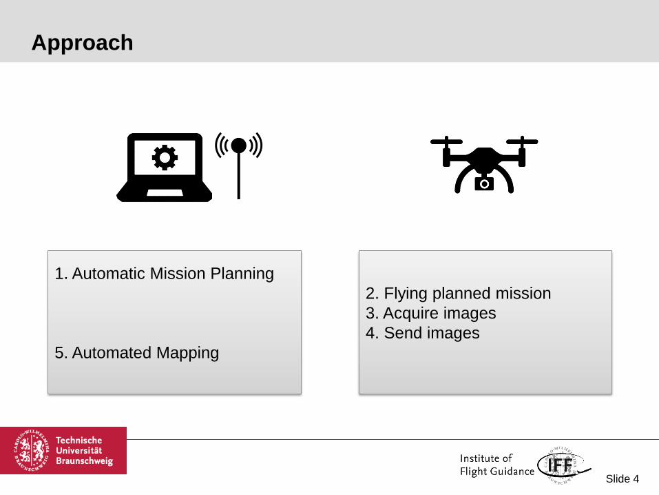
Approach
1. Automatic Mission Planning
5. Automated Mapping
2. Flying planned mission
3. Acquire images
4. Send images

Slide 5
Approach
1. Automatic Mission Planning
5. Live Mapping (ORB SLAM 2)
6. Photogrammetry (Agisoft)
2. Flying planned mission
3. Acquire images
4. Send images

Slide 6
Contents
Motivation
Approach
Hardware Setup
Software Setup
Structure
SLAM
Photogrammetry
Evaluation
Perspective
Slide 7
Contents
Motivation
Approach
Hardware Setup
Software Setup
Structure
SLAM
Photogrammetry
Evaluation
Conclusion

Slide 8
Hardware Setup - Copter
AirRobot AR200
220cm wingtip distance
3kg payload
12kg take-off weight
25min flight time
Payload
Gateworks GW5520 wifi board
Cortex A9 navigation PC
ADIS16488A IMU + uBlox M8T GPS
Slide 9
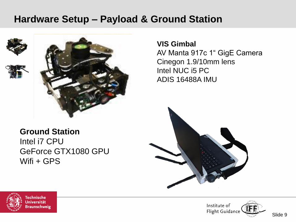
Hardware Setup – Payload & Ground Station
VIS Gimbal
AV Manta 917c 1“ GigE Camera
Cinegon 1.9/10mm lens
Intel NUC i5 PC
ADIS 16488A IMU
Ground Station
Intel i7 CPU
GeForce GTX1080 GPU
Wifi + GPS

Slide 10
Software Setup – ROS Structure

Slide 11
SLAM - Software Architecture
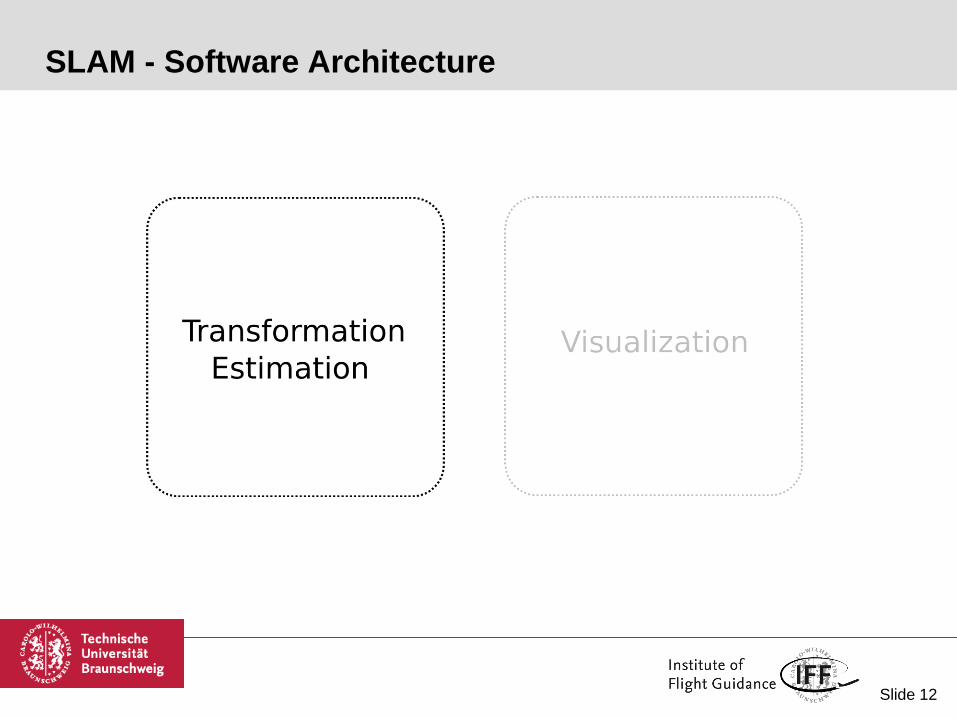
Slide 12
SLAM - Software Architecture
Slide 13
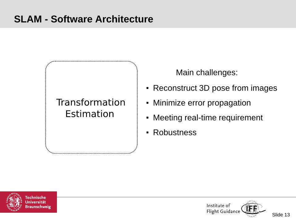
SLAM - Software Architecture
Main challenges:
▪ Reconstruct 3D pose from images
▪ Minimize error propagation
▪ Meeting real-time requirement
▪ Robustness

Slide 14
SLAM - Software Architecture
Main challenges:
▪ Reconstruct 3D pose from images
▪ Minimize error propagation
▪ Meeting real-time requirement
▪ Robustness
Visual SLAM frameworks

Slide 15
SLAM – ORB2 Process

Slide 16
SLAM - Common Reference Plane
Best fit from sparse
pointcloud
Best fit from fixed depth
projection
+ Also applicable without down
facing camera
- More complicated calculation
(outlier removal)
- Sensitive to depth variation of
environment
+ Robust to depth variation of
environment
+ Straightforward calculations
- Needs camera face down
Slide 17
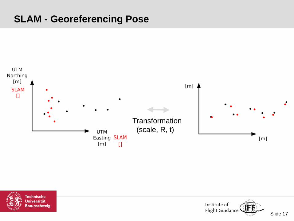
SLAM - Georeferencing Pose
Transformation
(scale, R, t)

Slide 18
SLAM - Software Architecture
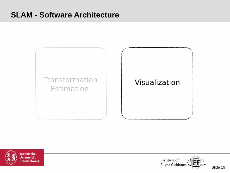
Slide 19
SLAM - Software Architecture

Slide 20
SLAM - Visualization strategies
1 Vary image resolution
Original
(100%)
Pose
estimation
(20 - 40%)
Final map
(80 - 100%)

Slide 21
SLAM - Visualization strategies
1 Vary image resolution
Original
(100%)
Pose
estimation
(20 - 40%)
Final map
(80 - 100%)
2 Visualize keyframes only
Slide 22
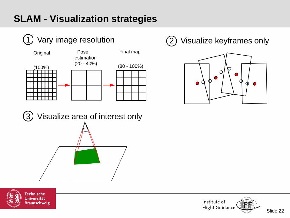
SLAM - Visualization strategies
1 Vary image resolution
Original
(100%)
Pose
estimation
(20 - 40%)
Final map
(80 - 100%)
2 Visualize keyframes only
3 Visualize area of interest only
Slide 23
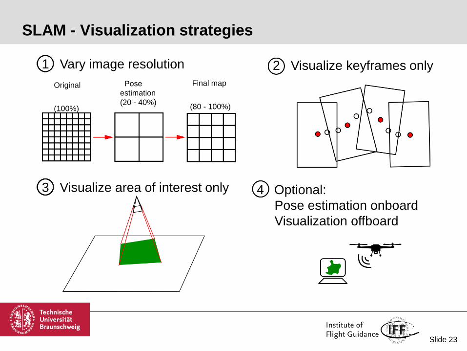
SLAM - Visualization strategies
1 Vary image resolution
Original
(100%)
Pose
estimation
(20 - 40%)
Final map
(80 - 100%)
2 Visualize keyframes only
3 Visualize area of interest only 4 Optional:
Pose estimation onboard
Visualization offboard

Slide 24
Photogrammetry
Agisoft Photoscan
• Image Alignment
• Mesh Generating
• Orthophoto
Generation
• Result Export
Python API
Script
• Triggers
Processing
Output
Folder
Photogr.
ROS Node
• Saves
Images
• Executes
API Script
• Publishs
Results
Input
Folder
ROS

Slide 25
Photogrammetry profiles

Slide 26
Evaluation
Mapping Flight
100m alt
75% Sidelap
3min
SLAM
99% Overlap 4.0Hz
864 images
Photogrammetry
75% Overlap 0.3Hz
47 images
Area: 150x100m
Ground Reference Points

Slide 27
Evaluation SLAM

Slide 28
Evaluation SLAM

Slide 29
Evaluation Photogrammetry

Slide 30
Evaluation SLAM VS Photogrammetry
Slide 31
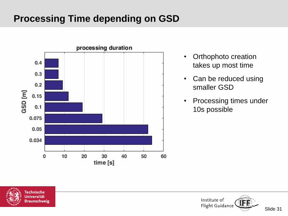
Processing Time depending on GSD
• Orthophoto creation
takes up most time
• Can be reduced using
smaller GSD
• Processing times under
10s possible

Slide 32
Summery
ROS based System for Aerial Survey and Image Transport
ORB SLAM 2 implementation for gereferenced image stitching
Photogrammetry ROS Node using Agisoft Photoscan
SLAM 2-3 times less accurate than Photogrammetry

Slide 33
Questions?

Slide 34
Outlook Competition
Multisensor equipped
UAV/UGV for automated
exploration
Appendix

Slide 35
IMAV2017 Competition
Feature Based Mapping
high overlap required
not so robust
not so fast
Pose Based Mapping
no overlap required
very robust
Very fast

Slide 36
Introduction – System-Design
Multisensor equipped
UAV/UGV for automated
exploration
UAV 1Hrafnas
UAV 2Hugin
UAV 3Mugin
UGV 1Geri
UGV 2Freki
GNSS X X X X X
IMU X X X X X
Comm. X X X X X
LiDAR X X X
RGB-Camera X
IR-Camera X X
Basic-Nav.
& Comm.
Ground
Station

Slide 37
Introduction – Software and Frameworks
Multisensor equipped
UAV/UGV for automated
exploration
Position(multi-constellation)
LiDAR-mapping
IFF-Navigation-Framework ROS-Framework
State-Vector(IMU/GNSS-Fusion)
2D-/3D-mapping
(RGB/IR-camera)
Slide 38
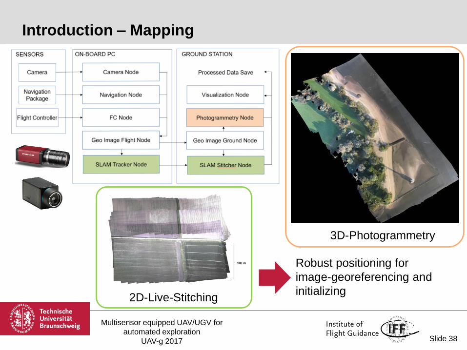
Introduction – Mapping
2D-Live-Stitching
3D-Photogrammetry
Multisensor equipped UAV/UGV for
automated exploration
UAV-g 2017
Robust positioning for
image-georeferencing and
initializing

Slide 39
Multi-Constellation – Availability
Multisensor equipped UAV/UGV for
automated exploration
UAV-g 2017
Increasing availability by using different GNSS-Systems at the same time
provides advantages in areas of degraded GNSS-reception (e.g. urban scenarios)

Slide 40
Multi-Constellation – Software implementation
Multisensor equipped
UAV/UGV for automated
exploration
IFF-Navigation-FrameworkSoftware-Implementation:
• Decoding of the navigation-raw-messages (u-blox protocol)
• Taking different Reference-Frames in account (geodetic and time)
• WGS84 (GPS), PZ-90 (GLONASS), GTRF (Galileo), CGCS2000 (BeiDou)
• Extension of the state vector to represent the different Time-References and
resultant extension of the Coupling-Filter (EKF)
Real-Time-Processing Post-Processing
Ԧ𝑥 = 𝑥 𝑦 𝑧 ∆𝑡𝐺𝑃𝑆∆𝑡𝐺𝐿𝑂∆𝑡𝐺𝐴𝐿∆𝑡𝐵𝐷𝑆𝑇

Slide 41
Multi-Constellation – Results
Multisensor equipped UAV/UGV for
automated exploration
UAV-g 2017
Availability (no shadowing effects)
• Cut-off elevation: 5° (common value for GNSS-Positioning)
• Number of satellites used in single-constellation case: 11 or less
• Number of satellites used in multi-constellation-case: 17 or less
• Number of received satellites: 21 to 23
Test Area near Peine
Slide 42
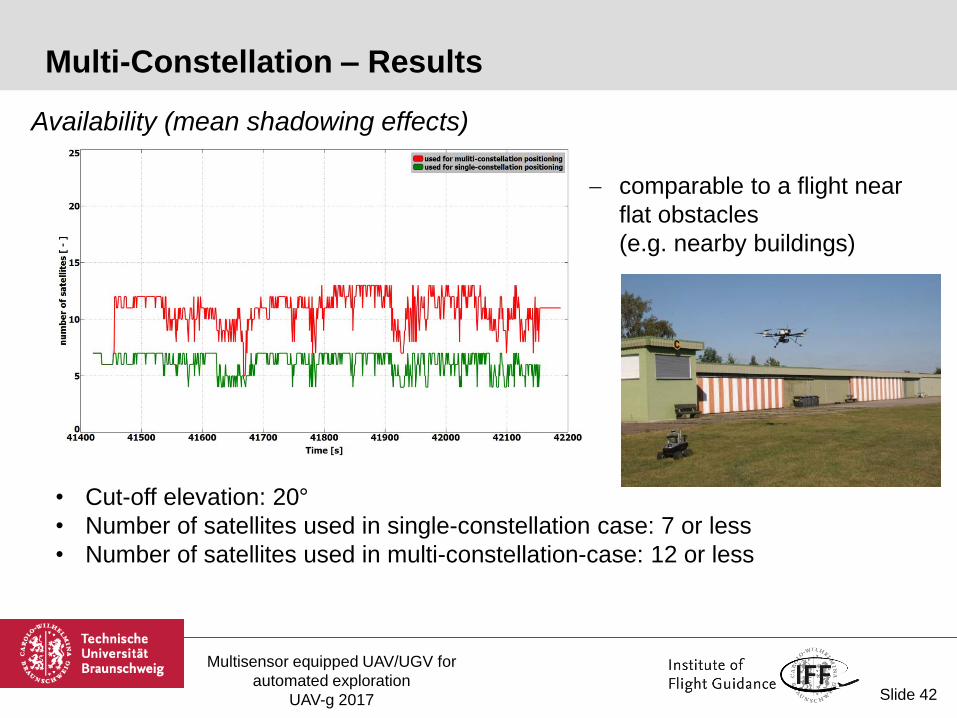
Multi-Constellation – Results
Availability (mean shadowing effects)
comparable to a flight near
flat obstacles
(e.g. nearby buildings)
• Cut-off elevation: 20°
• Number of satellites used in single-constellation case: 7 or less
• Number of satellites used in multi-constellation-case: 12 or less
Multisensor equipped UAV/UGV for
automated exploration
UAV-g 2017

Slide 43
Multi-Constellation – Results
Multisensor equipped UAV/UGV for
automated exploration
UAV-g 2017
• Cut-off elevation: 35°
• Number of satellites used in single-constellation case: 4 (minimum for positioning)
• Number of satellites used in multi-constellation-case: 7-8
Availability (shadowing effects)
comparable to a flight near
obstacles
(e.g. urban scenario)
in most cases enviromental
conditions for UGV

Slide 44
Approach 1: 2D-„live“-stitching (ORB-SLAM2 based)
• fast overview of the scenario
• good situational awareness
• information for further mission-planning
Mapping – Approaches
Multisensor equipped UAV/UGV for
automated exploration
UAV-g 2017
Slide 45
Mapping – 3D-Photogrammetry (RGB-Camera)
Multisensor equipped
UAV/UGV for automated
exploration
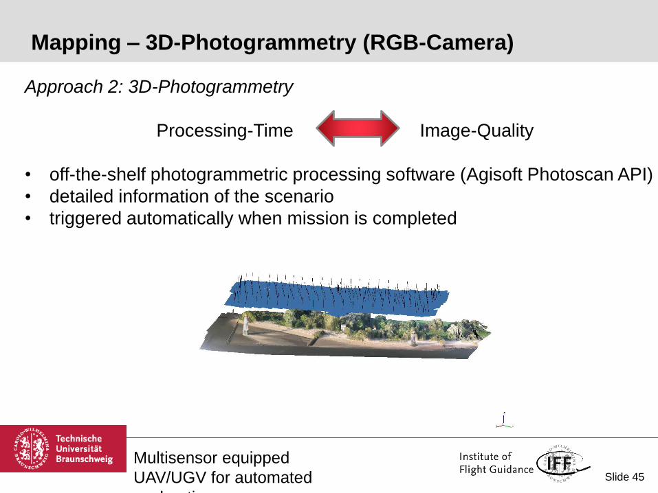
Approach 2: 3D-Photogrammetry
Processing-Time Image-Quality
• off-the-shelf photogrammetric processing software (Agisoft Photoscan API)
• detailed information of the scenario
• triggered automatically when mission is completed

Slide 46
Mapping – 3D-Photogrammetry (Thermal-Camera)
Multisensor equipped
UAV/UGV for automated
exploration
Thermal-Camera (FLIR A65)

Slide 47
Conclusion and Outlook
Conclusion
• Overview of the joint research project ANKommEn
• Benefit of using a multi-constellation based positioning
• adaption of the software-framework
• different approaches of mapping-processing
Outlook
• further optimization of the user interface (Ground Station)
• increasing the robustness of processes
• increasing the level of automation
Multisensor equipped
UAV/UGV for automated
exploration

Slide 48
Multisensor equipped UAV/UGV for
automated exploration
UAV-g 2017
Thank you for your attention!
Questions?
Slide 49
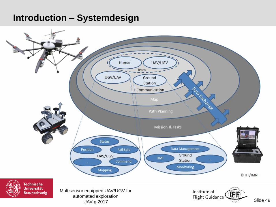
Introduction – Systemdesign
Multisensor equipped UAV/UGV for
automated exploration
UAV-g 2017

Slide 50
Hardware – Vehicle, Sensors and Processing-Units
Multisensor equipped UAV/UGV for
automated exploration
UAV-g 2017
UAV/UGV and Payloads
Processing-Units
Sensors
3x 2x

Slide 51
Multi-Constellation – Hardware
u-blox LEA M8T
GNSS-Systems GPS, Galileo, GLONASS, BeiDou
Features Carrier Phase Output, 2x PPS
Data-Output:
• NMEA-Data for NTP-Server (Phytec Board)
• Time-Synchronisation of the Overall-System
(Data-Processor, Sensors etc.)
• ubx-messages for Positioning (Raw-Data)
Analog Devices ADIS-IMU-16488
integrated IMU-breakout-board (custom-designed)
integrated magnetometer (heading)
Hardware
Multisensor equipped UAV/UGV for
automated exploration
UAV-g 2017

Slide 52
Approach 1: 2D-„live“-stitching (ORB-SLAM2 based)
• fast overview of the scenario
• good situational awareness
• information for further mission-planning
Mapping – Approaches
Multisensor equipped UAV/UGV for
automated exploration
UAV-g 2017