an automatic feature-based cutting tool selection...
TRANSCRIPT

International Journal of Current Engineering and Technology E-ISSN 2277 – 4106, P-ISSN 2347 – 5161 ©2015 INPRESSCO®, All Rights Reserved Available at http://inpressco.com/category/ijcet
Research Article
3193| International Journal of Current Engineering and Technology, Vol.5, No.5 (Oct 2015)
An Automatic Feature-based Cutting Tool Selection Approach for Turning Process Oussama Jaider†*, Ahmed Rechia†, Abdelilah El Mesbahi† and Hanae Zarkti†
†Department of Mechanical Engineering, University of Abdelmalek Essaadi, Faculty of Sciences and Technics, Tangier, Morocco
Accepted 21 Sept 2015, Available online 26 Sept 2015, Vol.5, No.5 (Oct 2015)
Abstract Selection of a proper cutting tool plays a significant role in achieving consistent quality and controlling the overall cost in an integrated manufacturing environment. The present paper describes on one hand, a novel method that treats extraction of GD&T and other technical data from STEP AP238. On the other hand, it presents an approach to build of a computer interface support for automatic tool selection for manufacturing features in a turning process. Data-tools were collected from recent Machining Handbook of world's leading manufacturer of tools, Sandvik Coromant. This application works conjointly with an automatic feature recognition system for rotational part. An example is given to show how this approach, systematically, leads to the choice of mini cutting tool packages for specific machining features. Keywords: CAD/CAPP/CAM, Manufacturing Feature Recognition, Automatic cutting-tool selection for turning. 1. Introduction
1 Process planning is an activity that consists in selecting the necessary processes, tools, appropriate parameters and operation sequencing to manufacture a part. The traditional way to solve process-planning problems is to leave it to the manufacturing experts that translate the global geometry of the part into a group of machining features well adapted each to a defined machining process, relying on their own experience. This manual approach is time consuming and usually, not consistent as the quality of the process plan depends on the planner’s experience (Oral, et al, 2004), (Nassehi, et al ,2011). Disadvantages of manual approaches led to development of automated approaches that aimed to reduce the probability of errors and inconsistencies. Computer Aided Manufacturing Process Planning is one of the most important advances in the area of manufacturing engineering, which plays a critical role linking Design and Manufacturing. CAPP determines automatically the use of available resources, including machines, cutting inserts, holders, appropriate machining parameters such as cutting speed, feed rate, depth of cut, and generates automatic sequences of operations and instructions to convert a row material into a required product with good surface finish (Duran, et al, 2008). The production cost of a manufacturing component depends upon cost of workpiece material, tooling cost, and recurring expenses. Thus, it is clear that the only *Corresponding author: Oussama Jaider
scope to reduce the overall cost of a workpiece is to focus on the tooling cost and machining time. Selecting an optimum insert, optimum cutting conditions, and optimum sequences affect directly the workpiece cost (Oral, et al, 2004). More than one hundred CAPP systems have been reported in the literature.
However, the link between CAD and CAPP systems is still not integrated as desired (Rao, et al, 2011). On one hand, the data of neutral files such as STEP, IGES generated by CAD systems consist of geometric and topological information, these data cannot be used for direct application to process planning, since CAPP systems require part form feature information, not geometric and topological information, CAD is usually geometry-based, whilst CAPP/CAM are feature-based and domain-dependent, which results in unsatisfactory practical implementation, or a common weakness of CAPP systems (Zhou, et al, 2007). On the other hand, Geometrical Dimensioning and Tolerancing (GD&T), surface roughness and technological data required for downstream applications are not embedded in the geometric model for the most of current CAD systems, which are lacking of appropriate data structure to admit them. CAD models seem to include these data as seen in the drawings, nonetheless, these data are not real attributes of CAD models but simply represented as text on the drawing (Kanga, et al, 2003).
Another problem is presented at the tool selection stage; a broad range of tool geometries is available to suit various practical applications and machining systems. As a consequence, the tool/process designer

Oussama Jaider et al An Automatic Feature-based Cutting Tool Selection Approach for Turning Process
3194| International Journal of Current Engineering and Technology, Vol.5, No.5 (Oct 2015)
has to wade through voluminous machining data handbooks and catalogues of cutting tools with different materials, coatings, geometries, and chip-groove configurations for high wear resistance and effective chip breaking. Consequently, process planners are forced to choose and recommend suboptimal cutting conditions (Wang, et al, 2007). The aim of this paper consists in linking automatically a feature recognition module with an automatic cutting tool selection module. Cutting tools and holders with their parameters are selected from the machining data handbook of Sandvik Coromant (Tool catalogue, 2012), to form a mini tool package related to each feature, based on many criterias, rules and machining design assumptions, and taking into account data related to machining features. The proposed methodology and system architecture are addressed in the following sections.
2. Literature review
There have been many attempts for automatic tool selection, determination of the optimum cutting conditions, and generation of optimum sequences of operations. Recently, various systems are using decision tables and decision trees for the automated and optimized selection of cutting tools. Oral & Cakir (Oral, et al, 2004) developed a modular system for automatic tool selection and sequence optimisation for rotational parts which is capable of selecting tools for face grooving, threading, internal turning, drilling, boring and internal recess/groove turning operations. Tool selection module uses knowledge such as geometry of workpiece (design features), surface finish, shape, location and direction, material of the workpiece, and machinability data. The developed system is based on ‘‘Rank Order Clustering’’ which uses a matrix that holds the diameters of the features and the tools that machine these features to generate tools and operation sequences for minimum tool changing. Balic & Cus (Babic, et al, 2011) developed an automatic cutting tool selection system that used neutral network (NN) to select tools for internal and external turning, including roughing and finishing operations. Tool selection depends on the shape of workpiece such as the approach and/or exit angle on one hand, and on the other hand, depends on the limitations of cutting tools such as cutting-edge angle and the nose angle. Mookherjee & Bhattacharyya (Moukherjee, et al, 2001) Used an expert system for tool selection, which automatically selects the appropriate turning tools and inserts as well as milling inserts, the material and the geometry, based on the requirement of the user. The main elements that influence the tool selection are: workpiece material, geometry, surface roughness, machine tool characteristics, workholders, and so on. Cutting conditions such as cutting speed and initial feed, depth of cut are selected from the machining handbook according to the grade of insert. Car & Barisic (Car, et al, 2009) developed a mathematical model for optimization of turning process parameters on CNC turning center. Optimization has been carried out by defining goal functions - minimum production
time. The mathematical model that describes machining operation has been defined as a combination of those functions whose variables are necessary for cutting parameters. The model consists of three separated models; tool life model which is considered as a goal function, cutting force model and cutting power model which are taken to be constrain functions that should not be violated. The success of optimization depends on defining the goal function - minimum production time. For each depth of the cutting optimization process, the optimal cutting parameters are given by a Generic Algorithm (GA). The binary linear programming optimization (LP) selects depths that have given the shortest machining time for total roughing depth. 3. Proposed methodology 3.1 Manual approach proposed by the manufacturer for tool selection Cutting tools consist of two main components: the tool holder and cutting insert. The objective of the manual tool selection approach is to determine several parameters for the holder, such as tool clamping system, type, entering angle, hand of cut, size, and so on. For the insert, some parameters to define are the shape of insert, size, grade, nose radius, geometry, and cutting conditions. The Machining Handbook of Sandvik Coromant is divided into three main categories, general turning, parting and grooving, and threading. In this paper, we presented the methodology of cutting tool selection for general turning. The first step for selecting cutting tools is to select the clamping system which depends on clamping possibilities available in turret/spindle. The second step consists in selecting the tool holder. Selecting a tool holder depends on the type of operation and clamping possibilities. For a good stability, a holder with the biggest size is recommended. The third step concerns selection of suiting insert. The choice of some parameters of insert is described as follow. For the shape of insert, the manufacturer gives a recommended shape of insert depending on the operation, e.g., insert with a point angle of 80° is recommended for longitudinal turning operations. Size of insert (L) depends on type of cut, and then on depth of cut. Notice that for every shape of insert, the total cutting edge length (La max) is given, e.g. for a rhombic 80° insert, La max is given in (1).
LLa3
2max
(1) La max must be bigger than the effective cutting edge length (La) which is given in (2).
)sin(Kr
apLa
(2)
Where Kr is the entering angle and ap is the depth of cut. The geometry of the insert is selected according to the type of cut and the material of the workpiece.

Oussama Jaider et al An Automatic Feature-based Cutting Tool Selection Approach for Turning Process
3195| International Journal of Current Engineering and Technology, Vol.5, No.5 (Oct 2015)
Fig.1 Flowchart of the manual tool selection approach proposed by Sandvik Coromant
The grade of insert depends on the type of cut, material to be machined, and the geometry selected. The final step concerns selection of cutting conditions. The manufacturer gives recommended depth of cut and feed rate for each insert selected. The recommended cutting speed is selected depending on the grade of insert, and on material properties of the workpiece, such as the specific cutting force and Brinell Hardness. To clarify the method of cutting tools choice proposed by the manufacturer, we gathered the major steps that lead to a choice of tools and holders for a given operation, and which are depicted in the flowchart of Fig. 1.
It is clear that the manual method of cutting tools choice presents some drawbacks and difficulties. On the one hand, the choice of holders and appropriate inserts according to the manufacturer's manual choice depends on several parameters and criteria, as well as on the expertise of the user who must manually select these parameters through the machining handbook in order to achieve a choice of tools for a given operation, which is time consuming. The manufacturer provides a recommended choice of cutting tools, but the optimization of the machining process can follow several alternatives. On the other hand, for best efficiency of CAPP systems, the integration and management of cutting tools is important since they represent the most dynamic resources.
In CAPP systems, the treated parts are broken down
into machining features. However, manufacturers of
tools such as Sandvik Coromant not follow the concept
of features. The choice of tools depends essentially on
the operations to be performed, and not on features to
machine. This problem can be resolved if the tool
selection is performed automatically and directly for
the machining features, which is the aim of this paper
and that is addressed in the following sections.
3.2. The proposed methodology for automatic tool selection 3.2.1. Automatic feature recognition (AFR) In a previous work, we have developed an automatic feature recognition system for rotational parts (Jaider, et al, 2014), which adopted an application protocol of the Standard for the Exchange of Product model data (STEP), defined as the international standard ISO 10303-203 (ISO10303-203, 2009). The proposed system for feature recognition consists of three modules namely Geometric and Topological Data Extraction module, feature recognition module and feature generator module. In the first module, dimensional and geometric data of the part are extracted from STEP file using Python programming.
Select insert geometry: PF, PM, PR, MF, MM, MR, KF…
Select insert grade: GC1515, GC1525, GC4205, GC4215…
YES
Select material of the workpiece: P, M, K, N, S, H
Recommended cutting condition of the selected insert:
Depth of cut, feed rate, and cutting speed
End
NO
Increase L or
decrease ap
Select type of cut: Finishing (F), Medium (M), Roughing (R)
Select
nose
radius
Select insert size (L) and depth (ap) of cut: La < La max?
Select Clamping system: Coromant Capto, shank tool
Select machining operation: Internal turning, external turning
Select type of operation: Longitudinal turning, facing, profiling, plunging
Appropriate holder (s): Coromant Capto, shank holder
Select insert shape: C, D, R, S, T, W, V, 55°
Start

Oussama Jaider et al An Automatic Feature-based Cutting Tool Selection Approach for Turning Process
3196| International Journal of Current Engineering and Technology, Vol.5, No.5 (Oct 2015)
The extracted data are converted into objects (created by Python classes) that are analyzed by a second module, and which consists in analyzing adjacent surfaces of each cylindrical, conical, toroidal, spherical and planar surface in a cylindrical component. A library which consists of turning-pre-defined manufacturing features is elaborated to enable the automatic feature recognition and extraction. The third module analyses the recognized features and build new features from interacting manufacturing features by extending their material surfaces to generate all possible interpretations of features. Possible combinations of features generated by the system for an example part are depicted in Fig. 2. It is clear from Fig. 2 that the types of features (two shoulders and two faces) for the five combinations are same, but dimensional parameters of features are different.
Fig.2 The five possible combinations generated from three interacting features for an example part
Adding to that, in each combination an order to machine features which is the same order in which features are built, is defined. This, leads to the generation of multiple process plans. At this stage, we cannot predict which combination will lead to the optimal process plan. Hence, introducing an optimized selection of tools, an optimized machining time and a sequence optimisation can plumb to the selection of an optimal process plan for an optimal combination of features.
3.2.2. Extraction of technical information from STEP file It is known that form features are not sufficient so that the part will be manufactured in a reasonable cost and will perform its intended function. Most researchers have concentrated on geometric information extraction and conversion without tackling the important problem of non-geometric feature information (Gao, et al, 2005). Technical information such as dimensions, surface condition and tolerance of geometric characteristics dictates the machining requirements and crucially affect the product cost (Zhao, et al, 2011). Few works have been done on incorporating the technical information into geometric model, and commercial CAD systems have disregarded this issue. In the most of CAD systems, GD&T data are modeled just as drawing (Zhao, et al, 2011). ISO 10303 AP 203 (boundary representation) is the only design data standard representation supported by
all CAD systems but it does not model tolerance items such as datum features, tolerances, and so on. A recent version, AP203 Edition 2, introduced the exchange of product data using a hybrid model containing construction history, GD&T, parameters and other high-level content. These GD&T definitions are mainly for annotation purposes; therefore they are not sufficient for automatic generation of dimensional measurement process plans (Zhao, et al, 2011). ISO 10303 AP 224 (ISO10303-224, 2006) (feature representation) models tolerance items but is not supported by CAD systems. STEP AP238 is the “Application interpreted model for computerized numerical controllers” (ISO10303-238, 2004). AP238, or more commonly “STEP-NC”, is a new standard for the exchange of comprehensive manufacturing data. STEP-NC offers accurate and complete product definition data from product design all the way to the machine tool. The advantage of STEP AP-238 is that it can work with the other STEP Application Protocols. AP-238 is fully integrated with other Application Protocols. This means where information is common to AP238 and another AP it can be processed using the same code and systems. A CAD system can read and process the geometry in an AP238 file because it has the same definition as the geometry in AP203 and AP214. The part features in AP238 are also the same as those in AP224 so as that systems that can process AP224 and AP240 can also process this data. For the reasons cited above, this section treats extraction of GD&T and other parameters related to the part such as surface roughness, and material, where STEP AP238 is chosen as input to the system for technical data extraction. The methodology of technical data extraction is as following:
After designing a part (without technical
information: GD&T, Ra, material) with a CAD software
such as CATIA V5, its STEP AP203 data file is
generated. This file is used as input to STEP-NC
Machine software (STEPtools, 2015), in which GD&T
and other parameters related to the workpiece can be
defined manually. It must be highlighted that GD&T are
affected by the user to surfaces of the part, however, in
STEP file, a cylinder is formed by joining two
ADVANCED_FACEs along two linear edges, thus, if for
example, the user wants to affect a tolerance to the
cylinder, he has to do it for both ADVANCED_FACEs. So,
once GD&T and other parameters are defined, the
workpiece is saved then as a STEP AP238 physical file
including the geometry of the part and its technical
information. This file is used on one hand, to recognize
and extract manufacturing features. On the other hand,
it is used in order to extract technical information
related to manufacturing features, required for
downstream activities such as automatic tool selection.
The architecture of the whole system is illustrated in
Fig. 3.
Oussama Jaider et al An Automatic Feature-based Cutting Tool Selection Approach for Turning Process
3197| International Journal of Current Engineering and Technology, Vol.5, No.5 (Oct 2015)
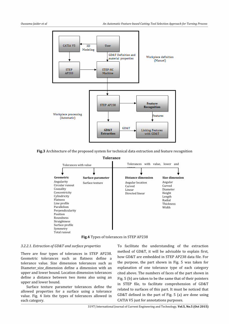
Fig.3 Architecture of the proposed system for technical data extraction and feature recognition
Fig.4 Types of tolerances in STEP AP238
3.2.2.1. Extraction of GD&T and surface properties
There are four types of tolerances in STEP AP238. Geometric tolerances such as flatness define a tolerance value. Size dimension tolerances such as Diameter_size_dimension define a dimension with an upper and lower bound. Location dimension tolerances define a distance between two items also using an upper and lower bound. Surface texture parameter tolerances define the allowed properties for a surface using a tolerance value. Fig. 4 lists the types of tolerances allowed in each category.
To facilitate the understanding of the extraction
method of GD&T, it will be advisable to explain first,
how GD&T are embedded in STEP AP238 data file. For
the purpose, the part shown in Fig. 5 was taken for
explanation of one tolerance type of each category
cited above. The numbers of faces of the part shown in
Fig. 5 (b) are taken to be the same that of their pointers
in STEP file, to facilitate comprehension of GD&T
related to surfaces of this part. It must be noticed that
GD&T defined in the part of Fig. 5 (a) are done using
CATIA V5 just for annotations purposes.
Size dimension
Angular Curved Diameter Height Length Radial Thickness Width
Geometric
Angularity Circular runout Coaxality Concentricity Cylindricity Flatness Line profile Parallelism Perpendicularity Position Roundness Straightness Surface profile Symmetry Total runout
Tolerances Tolerances with value, lower and
upper Tolerances with value
Surface parameter Surface texture
Distance dimension
Angular location Curved Linear Directed linear

Oussama Jaider et al An Automatic Feature-based Cutting Tool Selection Approach for Turning Process
3198| International Journal of Current Engineering and Technology, Vol.5, No.5 (Oct 2015)
(a) (b)
Fig.5 Example part: (a) toleranced part, (b) its advanced faces
Fig.6 A partial STEP AP238 text file of the definition of the toleranced diameter of the part of Fig. 5
A face entity defines a region on the surface of a part. In STEP file, a shell is formed by joining faces (denoted as ADVANCED_FACEs) along edges (Fig. 5 (b)). So, it is clear that the key entity that links surfaces of the part and GD&T related to these surfaces in STEP text file is assumed to be an ADVANCED_FACE. A toleranced face (ADVANCED_FACE) can be one of the four types; it can be an origin face (reference face), a target face (referenced face), a datum face, or a face having some properties (surface roughness, flatness, diameter…). Each toleranced face (ADVANCED_FACE) in STEP text file is put alone in one block starting with
an application object describing the type of the face. However, in some cases, more than one toleranced face can be in a same block, e.g., two adjacent cylinders having the same properties (block 1 in Fig. 6). Other functions are also put each in one block (block 2 and 3 in Fig. 6). The CALLOUT ( ) function defines a callout identifying a particular face on the part that can be a reference face, a referenced face, or a face having some properties (e.g. diameter, surface roughness…). As shown in Fig. 5, faces F243 and F247 have a specific diameter, which means that both faces have
/************************************************
* Application object: CALLOUT (#239)
* ITS_WORKPIECE: #239, #22, #21
* EXPLICIT_REPRESENTATION [*]: #239, #240, #241, #242, #243
* EXPLICIT_REPRESENTATION [*]: #239, #244, #245, #246, #247
* ITS_ID: #239, ['']
*/
#239=SHAPE_ASPECT('','',#22,.F.);
#240=PROPERTY_DEFINITION('','',#239);
#241=PROPERTY_DEFINITION_REPRESENTATION(#240,#242);
#242=REPRESENTATION('',(#243),#35);
#243=ADVANCED_FACE('Corps principal',(#139),#134,.T.);
#244=PROPERTY_DEFINITION('','',#239);
#245=PROPERTY_DEFINITION_REPRESENTATION(#244,#246);
#246=REPRESENTATION('',(#247),#35);
#247=ADVANCED_FACE('Corps principal',(#100),#134,.T.);
/************************************************
* Application object: DIAMETER_SIZE_DIMENSION (#255)
* APPLIED_TO: #255, #239
* DIMENSION_VALUE_TOLERANCE: #255, #256, #257, #258
* PLUS_MINUS_LIMITATION: #255, #259, #248
*/
#255=DIMENSIONAL_SIZE(#239,'diameter');
#256=DIMENSIONAL_CHARACTERISTIC_REPRESENTATION(#255,#257);
#257=SHAPE_DIMENSION_REPRESENTATION('',(#258),#35);
#258=(
LENGTH_MEASURE_WITH_UNIT()
MEASURE_REPRESENTATION_ITEM()
MEASURE_WITH_UNIT(LENGTH_MEASURE(140.),#251)
REPRESENTATION_ITEM('diameter size')
);
#259=PLUS_MINUS_TOLERANCE(#248,#255);
/************************************************
* Application object: TOLERANCE_PLUS_MINUS_VALUE (#248)
* LOWER_LIMIT: #248, #249
* UPPER_LIMIT: #248, #250
*/
#248=TOLERANCE_VALUE(#249,#250);
#249=(
LENGTH_MEASURE_WITH_UNIT()
MEASURE_REPRESENTATION_ITEM()
MEASURE_WITH_UNIT(LENGTH_MEASURE(-0.15),#251)
REPRESENTATION_ITEM('diameter size')
);
#250=(
LENGTH_MEASURE_WITH_UNIT()
MEASURE_REPRESENTATION_ITEM()
MEASURE_WITH_UNIT(LENGTH_MEASURE(0.15),#251)
REPRESENTATION_ITEM('diameter size')
);
/************************************************
Block 1
Block 2
Block 3

Oussama Jaider et al An Automatic Feature-based Cutting Tool Selection Approach for Turning Process
3199| International Journal of Current Engineering and Technology, Vol.5, No.5 (Oct 2015)
the same callout (block 1 in Fig. 6), denoted as CALLOUT (#239). The DIAMETER_SIZE_DIMENSION (#255) function defines implicitly the diameter of a cylinder. It has an attribute denoted as APPLIED_TO: #255, #239, where #239 is a pointer to the callout of faces F243 and F247. This function has a second attribute denoted as DIMENSION_VALUE_TOLERANCE: #255, #256, #257, #258, where #258 is a pointer to the value of the diameter (140) of the cylinder defined by F243 and F247. The function has a third attribute denoted as PLUS_MINUS_LIMITATION: #255, #259, #248, where #248 is a pointer to the identifier of the function below. The TOLERANCE_PLUS_MINUS_VALUE (#248) function defines an upper and lower bound of the cylinder diameter cited above. This function has two attributes, denoted as LOWER_LIMIT: #248, #249 and UPPER_LIMIT: #248, #250, where #249 and #250 are respectively the pointers to the lower bound value (-0.15) and upper bound value (0.15) of this diameter. The definition of the set of functions that define a diameter in the STEP AP238 file is shown in the flowchart of Fig. 7. The DATUM_FEATURE_FACE ( ) function defines one or more faces that are a reference point for a tolerance. Depending on the types of tolerance, datum information is required. For example, in Fig. 5, the parallelism tolerance must have datum information (A). As cited above, each tolerance is put in a block defining the type of the face. This means that DATUM_FEATURE_FACE (#260) function and the pointer to the face F264 are put in the same block, where #260 is an identifier (like a callout) to the face F264. The DATUM_DEFINED_BY_FEATURE (#265) function defines implicitly the name of the datum and the face for which the reference datum A is applied to. It has an attribute denoted as DATUM_NAME: #265, ['A'] that defines the name of the datum, and a second attribute denoted as DEFINED_BY: #265, #266, #260, where #265 is a pointer to the datum A, denoted as #265=DATUM('','',#22,.F.,'A'), and #260 is a pointer to the identifier of the reference face F264. In Fig. 5, F271 is a toleranced face, which is supposed to have a callout, defined as CALLOUT (#267). The PARALLELISM_TOLERANCE (#272) function defines a parallelism tolerance, it has an attribute denoted as TOLERANCE_VALUE: #272, #273, where #273 is a pointer to the value of the tolerance, which is given by the following records:
#273=( LENGTH_MEASURE_WITH_UNIT() MEASURE_REPRESENTATION_ITEM() MEASURE_WITH_UNIT(LENGTH_MEASURE(0.05),#251) REPRESENTATION_ITEM('circular runout') ); The PARALLELISM_TOLERANCE (#272) function has a second attribute that defines the referenced face
(F271), denoted as APPLIED_TO: #272, #267, where #267 is the pointer to the callout of the referenced face F271. This function has a third attribute that defines implicitly the reference datum (A) of F271, denoted as REFERENCE_DATUM [*]: #272, #274, where #274 is a pointer to the function DATUM_REFERENCE (#274). This function has an attribute that defines the reference datum to the face F271, denoted as REFERENCED_DATUM: #274, #265, where #265 is a pointer to the datum A. As noticed above, the CALLOUT ( ) function defines a callout identifying a particular face on the part, in figure v, F279 has a surface property, which means that this surface has a callout, denoted as CALLOUT (#275). The SURFACE_TEXTURE_PARAMETER ( ) function defines surface roughness to one or more faces, it has an attribute denoted as ITS_VALUE: #280, #281, where #281 is a pointer to the value and the type of surface roughness, which is given by the following records: #281=( LENGTH_MEASURE_WITH_UNIT() MEASURE_REPRESENTATION_ITEM() MEASURE_WITH_UNIT(LENGTH_MEASURE(0.8),#285) REPRESENTATION_ITEM('Ra') ); The SURFACE_TEXTURE_PARAMETER ( ) function has a second attribute denoted as APPLIED_TO: #280, #282, #283, #275, where #275 is a pointer to the callout of F279. Concerning the last type of tolerance in figure v (linear dimension),the DIRECTED_LINEAR_DISTANCE_DIMENSION (#292) function defines a distance between two surfaces, it has an attribute denoted as DIMENSION_VALUE_TOLERANCE: #292, #293, #294, #295, where #295 is a pointer to the value of the distance between F279 and F271, which is given by the following record: #295=( LENGTH_MEASURE_WITH_UNIT() MEASURE_REPRESENTATION_ITEM() MEASURE_WITH_UNIT(LENGTH_MEASURE(50.),#251) REPRESENTATION_ITEM('linear distance') ); The DIRECTED_LINEAR_DISTANCE_DIMENSION (#292) function has a second attribute that defines the target face, denoted as TARGET: #292, #267, where #267 is a pointer to the callout of the target face F271. And a third attribute that defines the origin face, denoted as ORIGIN: #292, #275, where #275 is pointer to the callout of the origin face F279. This function has a fourth attribute denoted as PLUS_MINUS_LIMITATION: #292, #296, #289, where #289 is an identifier to the TOLERANCE_PLUS_MINUS_VALUE (#289) entity. This function has two attributes, denoted as LOWER_LIMIT: #289, #290 and UPPER_LIMIT: #289, #291, where #290 and #291 are respectively the pointers to the lower bound value (-0.1) and upper bound value (0.1) of this dimensional distance.

Oussama Jaider et al An Automatic Feature-based Cutting Tool Selection Approach for Turning Process
3200| International Journal of Current Engineering and Technology, Vol.5, No.5 (Oct 2015)
Fig.7 Definition of a toleranced diameter according to STEP AP238
Fig.8 Definition of material properties in STEP AP238

Oussama Jaider et al An Automatic Feature-based Cutting Tool Selection Approach for Turning Process
3201| International Journal of Current Engineering and Technology, Vol.5, No.5 (Oct 2015)
After describing how GD&T and surface properties are embedded in the STEP AP238 data file, various strings and entities that represent GD&T functions are searched and located using Python. Python is based on object oriented programming, adding to that, the hierarchical structure of geometric and topological entities such as ADVANCED_FACEs was organized coherently as an object oriented data structure, as a result, GD&T related to each face (ADVANCED_FACE) and between faces are extracted easily and then, affected to features. 3.2.2.2. Extraction of material properties from STEP AP238 The material properties can be defined also by the user manually using STEP-NC Machine interface, where he can define material properties according to his needs. It must be noticed that the user has the freedom to enter the parameters that he wants through the software interface. The STEP AP238 covers material properties with the “ITS_MATERIAL ( )” function included in the “workpiece”. For the example part of Fig. 5, this function is denoted as ITS_MATERIAL: #140, #151, #152, #163, where #163 is a pointer to the function MATERIAL (#163) (Fig .8). This function has an attribute denoted as MATERIAL_IDENTIFIER: #163, ['ISO P: MC No. P1.2.Z.AN - CMC.01.2'] which reflects material properties for a type of steel, that the user has defined. The metal cutting industry produces a wide variety of components machined from many different materials. Each material has its own unique characteristics that are influenced by the alloying elements, heat treatment, hardness, etc. Therefore, workpiece materials have been divided into six major groups, in accordance with the ISO-standard, ISO P for steel, ISO M for Stainless steel, ISO K for Cast iron, ISO N for Non-ferrous materials, ISO S for HRSA and Titanium, and ISO H for Hardened steel. In the example part processed above, the user has defined ISO P, which is steel, the largest material group in the metal cutting area. The MC code can represent a variety of workpiece material properties and characteristics using a combination of letters and numbers such as P1.2.Z.AN, where: P is the ISO-code for steel 1 is the material group unalloyed steel 2 is the material sub-group for carbon content, C = 0.25–0.55% Z is the manufacturing process: forged/rolled/cold drawn AN is the heat treatment, annealed, supplied with hardness values
Some cutting tools suppliers use their own codes to classify materials, for example, Sandvik Coromant has used the so called CMC-code system (Coromant Material Classification) to identify and describe
materials from a variety of suppliers, standards and markets. With the CMC-system, materials are classified according to machinability, and Sandvik Coromant also provides suitable tooling and machining data recommendations. In the MATERIAL_IDENTIFIER: function, the user has also defined CMC.01.2, which is reflects the same material defined by the code P1.2.Z.AN according to ISO-standard. Both ISO MC and CMC classifications of materials can be found for example in the tooling catalogue of Sandvik Coromant. Thus, Python searches within the STEP text file of the workpiece the code in the MATERIAL_IDENTIFIER: function, this code is compared with those in the materials database, and then, material characteristics can be extracted. Taking the fact that GD&T related to each ADVANCED_FACE, between ADVANCED_FACEs, and surfaces (ADVANCED_FACEs) that constitute each feature are known, the next step consists in defining GD&T for each feature and between features. For the purpose, we subdivide tolerances into two categories, intrinsic tolerances, and extrinsic tolerances. An intrinsic tolerance can be defined as a tolerance related only to surfaces of the feature. It can be a geometric form tolerance, such as flatness, cylindricity, a surface having some properties such as surface roughness, a dimensional tolerance such as diameter, a linear distance and so on. It can be also a geometric tolerance of position or orientation applied between surfaces of a feature. The material is considered also as an intrinsic characteristic. An extrinsic tolerance can be defined as a tolerance between two features, otherwise, between two surfaces belonging to two different features. It can be a dimension tolerance such as linear distance, or a geometric tolerance of position or orientation. The extracted GD&T for features of the example part of Fig. 5 can be resumed and structured as shown in table 1. These technical data are necessary for defining applications (e.g. finishing) and for choosing cutting tools for features.
3.2.3. Architecture of the turning cutting tools database
Before introducing the new concept of automatic choice of cutting tools, it was necessary to collect from the catalog of Sandvik Coromant, all inserts and holders including their designations and parameters, cutting conditions and materials grades. For the purpose, a relational database was seized with MySQL Workbench and which is composed of several tables, a table of inserts and their attributes, a table of holders and their attributes, a table of materials, a table of inserts grade, a table of cutting conditions and so on. These tables are connected by relational links in such a way that relations between data of the manufacturer are respected (Fig. 9). For example, the inserts table is connected with holders table since the tool size and shape of insert must correspond with the seat size and shape of the holder. This database will be useful for the automatic extraction of all data necessary to design the developed system of automatic tool selection based on mini tools package.

Oussama Jaider et al An Automatic Feature-based Cutting Tool Selection Approach for Turning Process
3202| International Journal of Current Engineering and Technology, Vol.5, No.5 (Oct 2015)
Table 1 GD&T and surface properties of the part of Fig.5
Intrinsic tolerances
Extrinsic tolerances E1 E2 E3 E4 E1 E2 E3 E4 F1 C2 F3 C3 F4 F1 C2 F3 C3 F4
E1 F1 A
E2 C2 +0.15
D 140 -0.15
E3 F3 // 0.05
+0.1 50 -0.1
C3
E4 F4 Ra=0.8
Fig.9 Architecture of the cutting tools database 3.2.4. New concept based on tool package/machining feature In the literature, the majority of authors are based on recommendations made by the manufacturers to select tools and holders for desired operations (Moukherjee, et al, 2001), (Elmagrabi, et al, 2007). Recently, many authors use feature-based approaches, and then, the choice of tools is made from catalogs by selecting the operation that can achieve the feature. This choice is generally depending on the operation to be performed, such as longitudinal turning, facing, but not directly according to the machining feature. This prompted us to develop a new approach based on tool packages. A tool package contains a set of all inserts and holders that can ensure the machining of a manufacturing feature. Each tool pack is divided into mini-packs. Concerning the pack of holders, the user has the possibility to select only the
mini-pack of holders depending on clamping system available in the turret/spindle. The manufacturer gives shank tools and Coromant Capto tools as cutting units. Concerning inserts, the choice is fully automatic; packages of inserts are divided into mini-packs of inserts, including positive inserts, negative inserts, and ceramic/CBN inserts. Also, inserts are divided into mini-packs depending on the material to be machined and on the type of application. After a rigorous study of the catalog of the manufacturer, the system described above has been designed, and in which all inserts and holders that can insure the realization of each feature are selected to form mini tool packages depending on many criterias, rules and assumptions. As a result, the choice of tools becomes almost automatic for the manufacturing features. After giving a brief description of the philosophy of the system, the step which follows consists in explaining how a tool pack and a mini tool

Oussama Jaider et al An Automatic Feature-based Cutting Tool Selection Approach for Turning Process
3203| International Journal of Current Engineering and Technology, Vol.5, No.5 (Oct 2015)
package are designed taking into account the data of manufacturer on one hand, and on the other hand, part feature information.
3.2.4.1. Macroscopic cutting tools choice Taking the fact that machining features and their attributes are known, in a first step, a general analysis is performed for machining features without regard to their technical data. This analysis will form just tools packages for the recognized features, based on the type of features, and the operations proposed by the manufacturer of tools. So this first attempt will just identify candidate tools that form tools packages, and which will be subsequently analyzed to choose cutting tools that will form mini-packages of tools, required for machining features. According to the turning cutting tool catalogue of Sandvik Coromant, the operation type is the most critical parameter that determines some tools parameters such as the shape of the insert and the type of holder. Since the input data of our system are machining features, so, it is necessary to affect operations to features in order to achieve a choice of inserts and holders for the candidate features. Before affecting operations to features, all operations available in Sandvik Coromant tools catalogue have been identified at a first stage. Then, we have gathered these operations into classes of operations. Note that operations of a same class are characterised by the same movements of tool. An example of all external turning operations classes available in Sandvik Coromant tools catalogue are presented in table 2. In each class, a same operation can be performed by a set of inserts and holders that are almost different. For example, the class B in Fig. 10 is a longitudinal turning that uses different shapes of inserts and different holders with a diversity of entering angles. Taking the fact that all inserts and holders are grouped into classes according to operations, the next step consists in affecting operations to features. Machining features can be divided into two categories, simple features and complex features. Simple features are performed by using one machining operation, for example, a cylinder and a face can be machined by longitudinal turning and facing operations respectively. A groove is performed by a grooving operation. Complex features require at least two machining operations such as, convex and concave features, which require longitudinal turning and profiling operations. These types of surfaces are called Multiple Operation Surface (MOS) and have already been cited in the literature (Kayacan, et al, 1996). Thus, all classes of operations that can insure the machining of each feature are affected to the feature, to form tool package, containing only candidate inserts and holders required for the machining of the feature. For example, a recess feature can be performed by D and M classes of operations. A concave feature can be performed by G, D, A and B classes of operations for the fact that it requires longitudinal turning (roughing) and profiling operations. The results of the approach presented above are presented in table 3. It must be highlighted that for
each holder, there is an appropriate insert shape. Inserts are ranked according to recommendations in the catalogue of manufacturer. The letter S in the table represents special tools such as grooving and parting tools, which are not discussed in this paper. 3.2.4.2. Microscopic cutting tools choice Taking the fact that a tool package containing a set of insets and holders that are appropriate for the machining of each feature is obtained, a judicious analysis is done for candidate inserts and holders (of tool packages) of each feature on one hand, and on the other hand, for parameters and attribute of the concerned feature. So, in a second step, technical data and parameters of each feature are transferred to a rules-based and decision system that analyses these data on one hand. On the other hand, this system searches the parameter or parameters that should be determined for holders and inserts in the concerned tool package, adding to the determination of cutting conditions, according to each parameter of the feature. The input parameters of the feature can be described as following; GD&T, surface roughness of the feature, its geometry, its dimensions, its position, its accessibility, and the material of the workpiece. The determination of each parameter related to cutting tools according to feature parameters respects machining design assumptions, recommendations of the manufacturer and some concepts based on the literature. The developed system is limited to general turning
(grooving, parting and threading are not included) but
can be projected to other operations. The flowchart of
Fig.11 outlines the architecture of the system. Feature
parameters analysis is described as following:
Depending on surface roughness and intrinsic
tolerances related to each feature surfaces, a number of
applications is assigned, for example, a feature having a
surface roughness of 0.8 (Ra = 0.8) have to be
machined in three applications, roughing, semi-
finishing, and finishing application. The manufacturer
gives a tool geometry which depends on the type of
application and the material to be machined. For
example, the geometry PR is dedicated for roughing (R)
of steels (P). In finishing operations, surface roughness
is influenced by a compromise between feed rate and
nose radius of insert, which is given in (3).
R
fRa
²125
(3)
Where Ra is the arithmetic roughness, f is the feed rate, and Rε is the nose radius of the insert. In roughing operations, the biggest nose radius can be chosen to take advantage of greater strength and better reliability. But this must be balanced according to the variation of cuts required to avoid vibrations.

Oussama Jaider et al An Automatic Feature-based Cutting Tool Selection Approach for Turning Process
3204| International Journal of Current Engineering and Technology, Vol.5, No.5 (Oct 2015)
Table 2 Classes of operations for general turning according to Sandvik Coromant
Operation classes (Sandvik Coromant)
Operations (Sandvik Coromant)
Operation classes (Sandvik Coromant)
Operations (Sandvik Coromant)
A
H
B
I
C
J
D
K
E
L
F
M
G
Fig.10 Example of holders and inserts of B class of operations

Oussama Jaider et al An Automatic Feature-based Cutting Tool Selection Approach for Turning Process
3205| International Journal of Current Engineering and Technology, Vol.5, No.5 (Oct 2015)
Table 3 Results of tool packages formed for each machining feature
ID of MF Volumetric
feature Examples of appropriate holders in
tool packages for each feature
Appropriate inserts
S
Cylinder
** * * * * * * *
Face
* * * ** * * * *
Shoulder
** * * * * * * *
Rectangular groove
* *
Circular groove
** *
Ext
erio
r p
rofi
lin
g
Rec
ess
** * * * * *
** * * * * *
* *
**
** = Recommended insert shapes
The geometry of a feature such as a recess is characterized by the angle α shown in Fig. 12. This angle should be less than the trailing angle of the insert. The trailing angle can be determined by varying two parameters, the point angle of the insert r and
the entering angle of the holder, which is given by (4).
180'KrKrr (4)
Where Kr is the entering angle and Kr’ is the trailing angle

Oussama Jaider et al An Automatic Feature-based Cutting Tool Selection Approach for Turning Process
3206| International Journal of Current Engineering and Technology, Vol.5, No.5 (Oct 2015)
Fig.11 Flowchart of the microscopic tool parameters choice
Fig.12 Geometry of a recess feature Accessibility also influences the choice of the point angle of the insert and the entering angle of the holder. This point has already been addressed by Oral & Cakir (Oral, et al, 2004), and which consists in checking collisions in the case of nested recesses. The dimensions of the feature such as depth of the feature determines the maximum material to be removed from the stock in roughing operations and then, determines the size of the insert, adding to the maximum depths of cut to maximize productivity. This point was already presented by (1) and (2). The dimensions of the feature also determine the size of holder for machining inner diameters. The largest shank size is recommended to give maximum rigidity, minimum tool deflection and reduced tool overhang ratio. The feature position determines the hand of tool for both insert and holder, and the clearance angle of the insert and then for the holder. The manufacturer recommends positive inserts with a clearance angles
different to zero in case of machining of exterior features of thin workpieces and inner features. Negative inserts are recommended for exterior features and for roughing operations to insure a better stability. The position of the feature determines also the type of holder. Three types of holders are presented, holders for internal, external and frontal turning. Depending on the material of the workpiece, the type of application and the shape of the insert which are assumed already selected, the insert grade can be determined. The manufacturer gives the designations of materials and their characteristics such as Specific cutting force and Brinell hardness. Depending on the insert grade and the type of material, the manufacturer gives the recommended cutting speed and feed rate. Other recommended feed rates and depths of cut are also given for each insert. It must be known that some parameters related to tools are selected manually such as the clamping system and the coupling size of the holder. Other parameters such as thickness of the insert which is chosen according to the size of insert are selected automatically. Once the system has determined all parameters related to inserts and holders, adding to cutting conditions for the machining of each feature, and taking the fact that each parameter is coded by at least one letter or one number, it searches through the

Oussama Jaider et al An Automatic Feature-based Cutting Tool Selection Approach for Turning Process
3207| International Journal of Current Engineering and Technology, Vol.5, No.5 (Oct 2015)
tools database of catalogued tooling matches. Once such a match is determined, the system stores the whole code key of each tool in another database to form mini tool packages for candidate features.
4. Simple example part
The developed approaches for feature recognition, technical data extraction, and automatic tool selection have been applied to the simple workpiece shown in Fig. 13. The material of the workpiece is taken to be steel (P), and surface roughness of 0.8µm has been taken for surfaces of all features for simplification and in order to generate tools for roughing, semi-finishing and finishing operations for all features. After designing the part with CATIA V5, the physical STEP AP203 file is generated and transferred to STEP-NC
Machine software to define surface roughness for part surfaces. After generating a STEP AP238 file, feature recognition and technical data extraction are performed. Three features are identified, a shoulder, a face and a recess. The system for feature recognition generates two combinations of features since the face and the shoulder are interacting (the recess is excluded from interactions). Each combination has to be treated by the automatic tool selection module separately. Taking the fact that features are identified, surface roughness of each feature are known, at first stage, tool packages are defined for each feature as already explained in section 3.2.4.1. At a second stage, some features parameters and attributes are analysed. For each feature, tools are selected to form a mini package of tools.
Fig.13 Simple workpiece
Table 4 Suitable Inserts selected for the machining features
Application Machining feature
Shoulder Face Recess
Roughing CNMG 19 06 08-PR SNMG 19 06 08-PR DNMG 15 04 08-PR
CNMG 19 06 12-PR SNMG 19 06 12-PR DNMG 15 04 12-PR
CNMG 19 06 16-PR SNMG 19 06 16-PR DNMG 15 04 16-PR
CNMG 19 06 24-PR SNMG 19 06 24-PR DNMG 15 06 08-PR
CNMM 19 06 12-PR SNMM 19 06 12-PR DNMG 15 06 12-PR
CNMM 19 06 16-PR SNMM 19 06 16-PR DNMG 15 06 16-PR
CNMM 19 06 24-PR SNMM 19 06 24-PR DNMM 15 06 08-PR
CNMG 19 06 12-XMR SNMG 19 06 12-XMR DNMM 15 06 12-PR
CNMG 19 06 16-XMR SNMG 19 06 16-XMR DNMM 15 06 16-PR
CNMM 19 06 16-WR SNMG 12 04 08-XMR
CNMG 12 04 08-PR SNMG 12 04 12-XMR
CNMG 12 04 12-PR SNMG 12 04 16-XMR
CNMG 12 04 16-PR SNMG 12 04 08-PR
CNMG 16 06 08-PR SNMG 12 04 12-PR
CNMG 16 06 12-PR SNMG 12 04 16-PR
CNMG 16 06 16-PR SNMG 15 06 08-PR
CNMG 16 06 24-PR SNMG 15 06 12-PR
CNMG 25 09 24-PR SNMG 15 06 16-PR
CNMG 12 04 08-XMR SNMG 15 06 24-PR
CNMG 12 04 12-XMR SNMG 25 07 16-PR
CNMG 12 04 16-XMR SNMG 25 07 24-PR
CNMG 16 06 12-XMR SNMG 25 09 24-PR
CNMG 16 06 16-XMR
(semi-finishing) CNMG 12 04 04-PM DNMG 11 04 04-PM
CNMG 12 04 08-PM DNMG 11 04 08-PM
CNMG 12 04 12-PM DNMG 11 04 12-PM
CNMG 12 04 16-PM DNMG 15 04 04-PM
CNMG 12 04 04-XM DNMG 15 04 08-PM
CNMG 12 04 08-XM DNMG 15 04 12-PM
CNMG 12 04 12-XM DNMG 15 06 04-PM
DNMG 15 06 08-PM
DNMG 15 06 12-PM
DNMG 15 06 16-PM
DNMG 15 04 04-XM
DNMG 15 04 08-XM
DNMG 15 06 04-XM
DNMG 15 06 08-XM

Oussama Jaider et al An Automatic Feature-based Cutting Tool Selection Approach for Turning Process
3208| International Journal of Current Engineering and Technology, Vol.5, No.5 (Oct 2015)
Finishing CNMG 12 04 04-PF DNMG 11 04 04-PF
CNMG 12 04 08-PF DNMG 11 04 08-PF
CNMG 12 04 12-PF DNMG 11 04 12-PF
CNMG 12 04 04-XF DNMG 15 04 04-PF
CNMG 12 04 08-XF DNMG 15 04 08-PF
DNMG 15 04 12-PF
DNMG 15 06 04-PF
DNMG 15 06 08-PF
DNMG 15 06 12-PF
DNMG 15 04 04-XF
DNMG 15 04 08-XF
DNMG 15 06 04-XF
DNMG 15 06 08-XF
Fig.14 Inserts generated by a Sandvik android application for the needed operations For the huge number of suitable inserts for the example part, we have limited inserts to the recommended inserts proposed by the manufacturer, to negative inserts (T-MAX P) and to a new generation of inserts named multi-materials inserts. Thus, table 4 illustrates the selected inserts for each feature and for each application. Holders have not been shown in this table since inserts present the most consumable tools that affect machining cost. It is important to notice that the whole system have not been fully implemented yet, and then, the content of table 4 has been entered manually. To confirm this selection, we have referred to an android application of Sandvik Coromant (Turning Multi Materials, 2015). Note that the choice of tools in the application depends on the operation (e.g. Profiling), and not on features. The number of operations available is limited to four major choices. Thus, for our case, the same operation (longitudinal turning/facing) is selected for both shoulder and face features. The results of the application are depicted in Fig. 14.
5. Discussion and conclusion
In this paper, we first gave an overview of the method we have developed regarding the recognition of machining turning features. This step is crucial for the integration of CAD / CAPP systems. When several
interacting features arise, several combinations of features are generated, for each combination, an order to machine features is well defined. Adding to that, each combination must be treated by the tool selection module. The number of combinations can be reduced if we take into consideration GD&T and economic and technological constraints that create precedence between features, and thereafter, some combinations for which the orders to build (which is the same order to machine features) features violate these constraints are deleted and will not be processed by the system of cutting tool selection. The method of cutting tool selection we have developed introduces a new concept based on forming mini tool packages that are required for the machining of the recognized features. A tool package is formed by taking into account the types of features. After that, the system determines the parameters for cutting tools from tools available in the tool package according to parameters and attributes of features. Once all parameters of tools are determined, several series of letters and numbers that represent the tool parameters are stored. The system searches through the database of manufacturer codes that correspond to these coded series. Thereafter, the tools are stored to form a mini tool package related to each feature. In the literature, several cutting tool selection systems have been developed, however, as far as we are concerned, many of these systems confront some

Oussama Jaider et al An Automatic Feature-based Cutting Tool Selection Approach for Turning Process
3209| International Journal of Current Engineering and Technology, Vol.5, No.5 (Oct 2015)
difficulties. Arezoo & Ridgway (Arezoo, et al, 2000) developed a system for selecting tools that lacks a feature recognition module. We believe that the architecture for the definition of basic objects for the cutting tool selection system, such as the workpieces characteristics, and tools characteristics, seems to be absent and is not well explained. The choice of the holder is in line with the method proposed by the manufacturer, however, it is preferable to make the choice of the insert first because an adjustable tool holder can be provided, and that can withstand more than one insert shape. In another system developed by Mookhrejee & Bhattacharyya (Moukherjee, et al, 2001), the choice of tools parameters are in details, however, this choice is guided by the user and is not dependent of part features and their characteristics, such as the surface roughness, GD&T, the geometry of the feature, and so on. Thus, this system cannot be directly linked to CAPP systems. Oral & Cakir (Oral, et al, 2004) introduced the concept of features for the selection of cutting tools, however, the choice of parameters for the insert such as the size, the grade, the geometry, the choices of cutting conditions, as well as the relationship between these parameters and features characteristics are not well explained. This system lacks a set of tools for machining a specified feature. The initial choice of an insert starts by choosing the largest point angle (shape of insert), if the tool has collisions with the workpiece, the point angle is reduced until the right tool is found. This method seems time consuming since it deals with all the tools available in the database regardless of some feature parameters. Another system developed by Balic & Cus (Babic, et al, 2011) also introduced the concept of features. the choice of tools for features depends both on the geometry of the feature which is characterized by the angle of approach and the exit angle, and the other limitations of the tools, such as the entering angle of the holder and the nose angle (point angle) of the insert. However, the choice of parameters related to the insert such as its geometry, its grade, size, and the choice of cutting conditions and their influence on the surface finish of the workpiece are not explained.
Through these issues, it is clear that the novel
concept of tools-packages we have developed will
facilitate on one hand the selection and integration of
tools in CAPP system, and on the other hand, it will
reduce the time required to find appropriate tools
through the catalog of Sandvik Coromant for a given
feature. However, this method results in most cases to
several inserts with different sizes and shapes. It must
be highlighted that the size of insert and the depth of
cut present crucial parameters affecting the total
machining time, which is also influenced by the tool
change time, by tool travel time, and operation
sequencing. These issues will be addressed in a future
work.
References Ali Oral, M. Cemal Cakir, Automated cutting tool selection and
cutting tool sequence optimisation for rotational parts, Robotics and Computer-Integrated Manufacturing 20 (2004) 127–141.
X. Zhang, A. Nassehi, V.G. Dhokia, S.T. Newman, “Refining Process Logic From CNC Part Programmes for Integrated STEP-NC Compliant Manufacturing of Prismatic Parts” 4th International Conference on Changeable, Agile, Reconfigurable and Virtual Production (CARV2011), Montreal, Canada 2011 p. 333.
Orlando Duran, Nibalbo Rodriguez, and Luiz Airton Consalter, Automatic Selection of Cutting Tools Geometry Using an Evolutionary Approach, IEA/AIE 2008, LNAI 5027, pp. 561–569, 2008.
D. Sreeramulu, C.S.P.Rao, A new methodology for recognizing features inrotational parts using STEP data exchange standard, International Journal of Engineering, Science and Technology, Vol. 3, No. 6, 2011, pp. 102-115.
Xionghui Zhou, Yanjie Qiu, Guangru Hua, Huifeng Wang and Xueyu Ruan, A feasible approach to the integration of CAD and CAPP, Computer-Aided Design 39 (2007) 324–338.
M. Kanga, J. Han, J.G. Moon, An approach for interlinking design and process planning, Journal of Materials Processing Technology 139 (2003) 589–595.
X. Wang, Z.J. Da, A.K. Balaji, I.S. Jawahir, Performance-Based Predictive Models and Optimization Methods for Turning Operations and Applications: Part 3— Optimum Cutting Conditions and Selection of Cutting Tools, Journal of Manufacturing Processes Vol. 9/No. 1 2007.
Tool Catalog, turning tools. Sandvik Coromant, 2012. J. Balic, F. Cus and B. Vaupotic, Intelligent automatic cutting-
tool selections for turning operations, ICGST AIML-11 Conference, Dubai, UAE, 12-14 April 2011.
R. Moukherjee and B. Bhattachariyya, development of an expert system for turning and rotating tool selection in a dynamic environement, Journal of Materials Processing Technology 113 (2001) 306-311.
Z. Car, B. Barisic and M. Ikonic, GA based CNC turning center exploitation process parameters optimisation, ISSN 0543-5846, METABK 48(1) 47-50 (2009), UDC – UDK 004.896:621.9-52:004.421=111.
Jaider Oussama, Elmesbahi Abdelilah, Rechia Ahmed, Manufacturing Computer Aided Process Planning For Rotational Parts. Part 1: Automatic Feature Recognition From STEP AP203 Ed2, Int. Journal of Engineering Research and Applications, ISSN: 2248-9622, Vol. 4, Issue 5 (Version 1), May 2014, pp.
STEP Application Protocol (AP) 203 editions 1 & 2, Configuration Controlled 3D Designs of Mechanical Parts and Assemblies, ISO10303 1994, (2007) & (2009).
Jian Gao, De Tao Zheng, Nabil Gindy, Doug Clark, Extraction/conversion of geometric dimensions and tolerances for machining features, Int J Adv Manuf Technol (2005) 26: 405–414, DOI 10.1007/s00170-004-2195-3
Yaoyao Zhao, Xun Xu, Tom Kramer, Fred Proctor, John Horst, Dimensional metrology interoperability and standardization in manufacturing systems, Computer Standards & Interfaces 33 (2011) 541–555
ISO, ISO 10303-224: Industrial automation systems and integration -Product data representation and exchange - Part 224: Application protocol: Mechanical product definition for process planning using machining features. 2006.

Oussama Jaider et al An Automatic Feature-based Cutting Tool Selection Approach for Turning Process
3210| International Journal of Current Engineering and Technology, Vol.5, No.5 (Oct 2015)
ISO TC 184/SC4/WG3 N1089, 2004. ISO/DIS 10303- 238: Industrial automation systems and integration Product data representation and exchange Part 238: Application Protocols: Application interpreted model for computerized numerical controllers. Geneva, Switzerland.
http://www.steptools.com/products/stepncmachine/ N.H. Elmagrabi, F.M. Shuaeib and C.H.C. Haron, An overview
on the cutting tool factors in machinability assessment, Journal of Achievements in Materials and Manufacturing Engineering, Received 30.03.2007; published in revised form 01.08.2007.
MC. Kayacan, I.H. Filiz, A.I. Sijnmez, A. Baykasoglu and T. DERELI, OPPS-ROT: An optimised process planning system for rotationalparts, Computers in Industry 32 (1996) 181-195.
http://www.sandvik.coromant.com/fr-fr/knowledge/ calculators_and_software/apps_for_download/pages/turning-multi-materials.aspx
B. Arezoo, K. Ridgway, A.M.A. Al-Ahmari, Selection of cutting tools and conditions of machining operations using an expert system, Computers in Industry 42 _2000. 43–58.